

Nitek EL1551U User Manual
INSTALLATION GUIDE
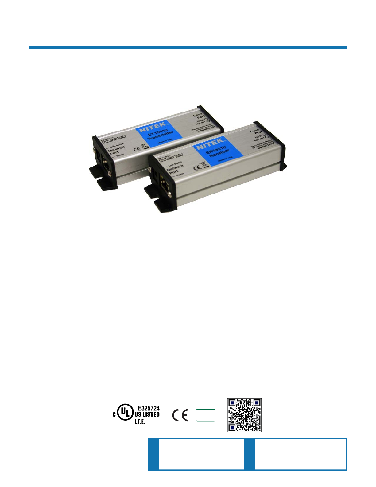
EL1551U
IP Video Camera Over Single Twisted Wire
Ethernet Extender with EtherStretch
Description
The EL1551U is another component of the NITEK EtherStretch line. This Environmentally hard-
ened EtherStretch solution allows for the utilization of existing cable infrastructure (coax or UTP)
to transmit data from IP cameras and other network devices along with PoE power to operate
these networked devices well beyond standard network limitations. The EL1551U can extend
Ethernet to over 460m or 1500ft of single twisted pair wire making the EL1551U is ideal for retrofit-
ting existing installations.
The EL1551U system consists of a transmitter and a receiver unit that require very little installation
time and no set up or configuration. The system quickly turns any ordinary single twisted pair wire
into a high speed network communication for distances up to 460 meters or 1500 ft.
The EL1551U is completely transparent to the network thus requiring no IP or MAC addressing.
Simply connect your network devices to the networking port of the transmitter and receiver units
and use the with existing cabling infrastructure. LED indicators show the status of the network communications and PoE power.
The NITEK EtherStretch EL1551U reliably extends network communications and overcomes cable
distance limitations offering connectivity to devices in locations traditional networking does not allow. The units are constructed of industrial grade RoHS compliant plated aluminum with a corrosion
resistant finish makes them extremely durable.
06072013
IEC/UL 60950-1
NITEK ®
COMPLIANT
2002/95/EC
5410 Newport Drive, # 24
Rolling Meadows, IL 60008
Phone: (847) 259-8900
Fax: (847) 259-1300
USA
E-mail: info@nitek.net
WWW.NITEK.NET
RoHS
De Schans 19-21 2a
8231 KA Lelystad
Tel: +31(0)320-230005
E-mail: info@nitek.nl
WWW.NITEK.NL
EUROPE

Important Safety Instructions
Read all Safety Instructions.
Keep the Instructions for future reference.
Be sure to HEED
Follow ALL
DO NOT
Clean this device ONLY
DO NOT
Install in accordance with the manufacturer’s instructions.
DO NOT
amplifiers) that produce heat.
DO NOT
one blade wider than the other. A grounding plug has two blades and has a third grounding prong. The wide
blade and the grounding prong are provided for your safety. If the provided plug does not fit into your outlet,
consult an electrician for replacement of the obsolete outlet.
DO NOT
overloaded when the ratings listed on the unit are considered.
Protect the power cord from being walked on or pinched especially at plugs, convenience receptacles and other
points where they exit from the device.
Only use attachments and/or accessories specified by the manufacturer.
use this device or any of the equipment described, near water.
block any ventilation openings.
install near any heat sources such as radiators, heat registers, stoves or other apparatus (including
defeat the safety purposes of polarized or grounding type plugs. A polarized plug has two blades, with
connect the unit to an electrical supply if the wiring or over current protection of the supply could be
all Warnings.
instructions.
with a dry cloth.
Refer all servicing to qualified service personnel. Servicing is required when the device has been damaged in any
way, such as the power supply cord or plug is damaged, liquid has been spilled on, or objects have fallen into the
device, the device has been exposed to rain or moisture, does not operate normally or has been dropped.
WARNING: To reduce risk of fire or electric shock, do not expose this apparatus to rain or moisture.
Installation shall be performed ONLY
Unless the device is specifically marked as a NEMA 3, 3R, 3S, 4, 4X, 6 or 6P enclosure, it is designed for indoor
use ONLY
and it must not be installed where exposed to rain or moisture.
by qualified personnel and must conform to all local codes.
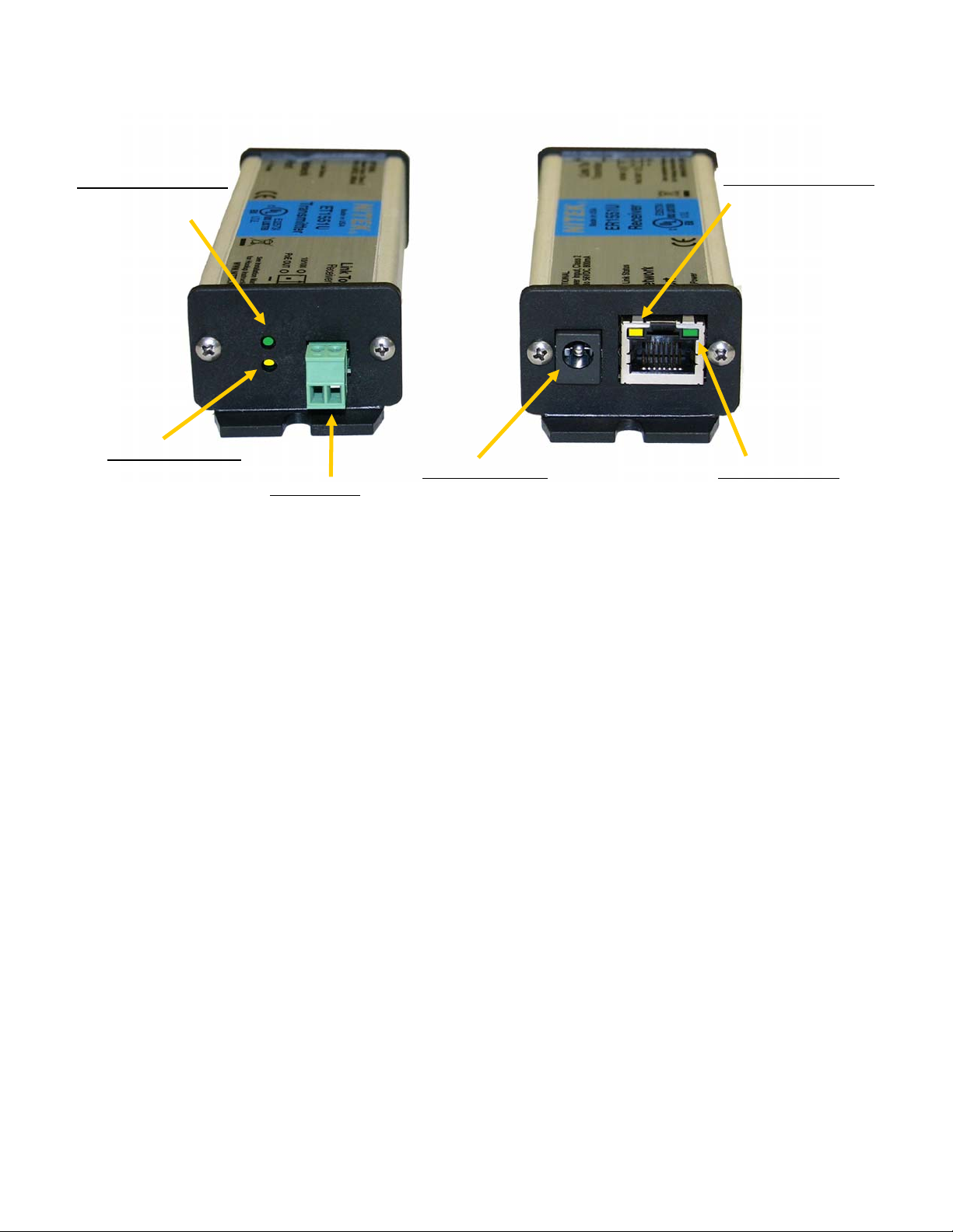
Parts of the EL1551U
UTP Side of Device
10/100 Link LED Indicator
• On Solid = 100Mb
• Flashing = 10Mb
• Off = No Link
PoE Out LED Indicator
• On = PoE is being provided
out the network port
• Off = PoE is “not” being sent
out the network port
UTP Connector
• Attaches to twisted
pair wires
Network Port Side
Link Status LED Indicator
• On Solid = Ethernet Link
• Off = No Ethernet Link
Optional Power Input
• Class II 48-56VDC input to create PoE
in installations where a PoE switch is
not available.
• On Receiver used to power the system
when a PoE switch is not available.
• On Transmitter used to provide greater
PoE power out the network port.
Power LED Indicator
• On Solid = The Unit is powered
and ready to use
• Off = The unit is not powered
Installation Considerations
Wire and Cable Recommendations: The EL1551U is designed for use with copper based 24AWG
Twisted Pair (CAT3 or CAT5) cable. Other heavier gage wires are possible but the wire must be a
twisted paired cable. The RJ45 network port pin out schemes shall be in accordance with the 568B
standard. The quality of which must be consistent with any reasonably serviceable cable condition.
Cables should be free from damage as in cuts, breaks, or cracks to the outer covering and insulated
shielding which may compromise the signal conductivity of the cable.
For more specific information regarding wire types, gauges, and proper installation techniques
please call Tech Support at (847)259-8900 or (800)528-4343.
Ethernet: The EL1551U is designed to transmit and receive up to 100Mbps of Ethernet data to a
maximum distance of 1,600ft / 500m. Before considering this solution be sure that the cable involved
does not exceed the recommended maximum lengths. If the cable distance value is undetermined at
the time of installation, we recommend the use of a Time Domain Reflectometer (TDR) or other
method to determine the unknown cable distance estimates.
 Loading...