

Page 1
Hardware Installation Manual
Copyright 2014-2015 Nistune Developments
Page 2

Table of Contents
Overview ...........................................................................................................................................................................3
Flex Fuel ............................................................................................................................................................................4
Launch Control Operation...............................................................................................................................................17
Variable Cam Timing Output...........................................................................................................................................20
Page 2 of 27
Page 3

Overview
This is the first edition of the Nistune feature pack. The feature pack offers enhanced features over the standard ECU
for a selected range of vehicles.
The standard ECU code has been modified using patch code to provide the most customers requested features. We
do plan to add more features when possible in the future.
This document covers the ECU modifications required to use Flex fuel and Launch Control features
Page 3 of 27
Page 4
Flex Fuel
Flex fuel sensors measure the ethanol content of fuel passing through it and report the rating as a percentage. The
sensors output a frequency and a converter is required to translate this into a voltage which can be read by the ECU.
Nistune will read the flex fuel input via diagnostic connector input on the ECU. This requires modification of the
Nissan ECU hardware. A flex fuel kit comprising a sensor and content analyser is required.
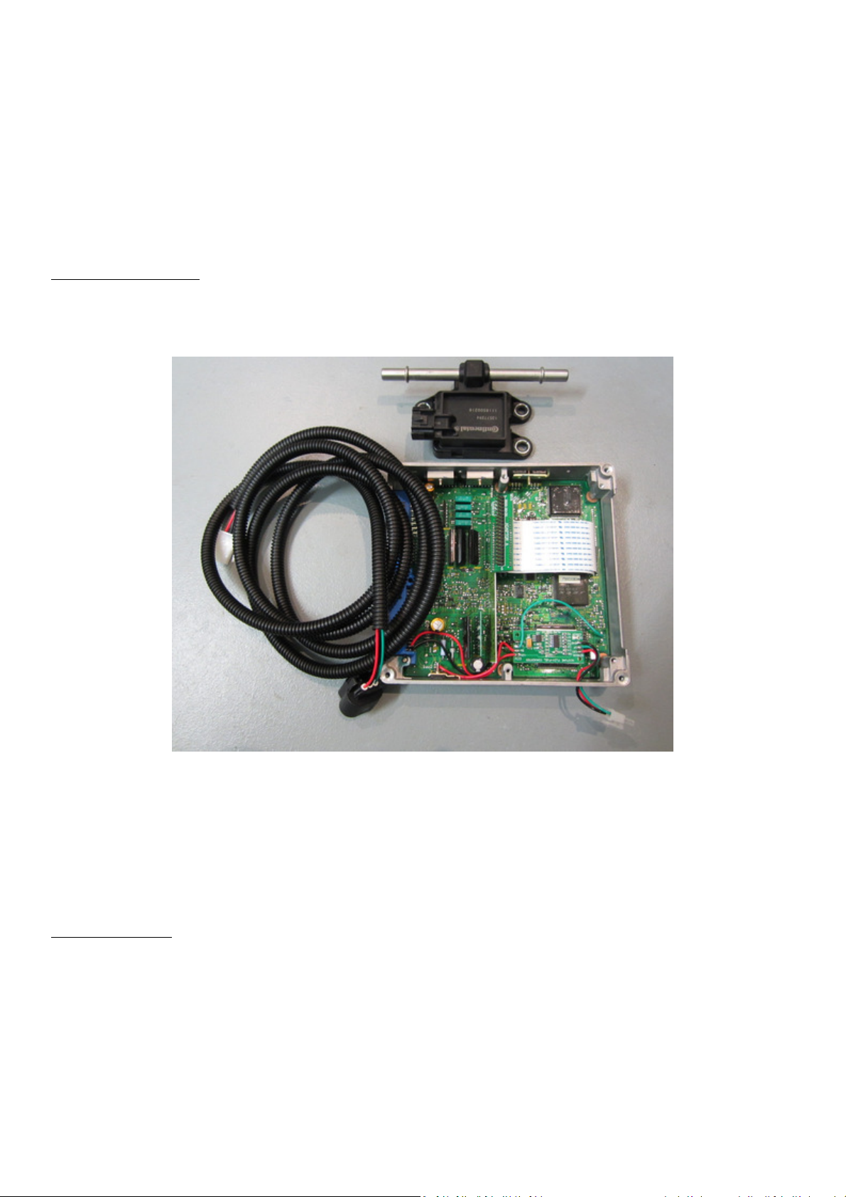
Nistune Flex Converter
Nistune have developed a content analyser board which is internally mounted to the ECU. It will be sold with the
board and flex cable. Flex fuel sensors can be purchased separately.
The flex board is mounted to the top of existing components using durable double sided table.
BLACK - GND
RED – 12V
GREEN – Input
Run a 5 volt line from the regulator to the 5V input
Sensor Installation
WARNING: Competent professionals must install the flex fuel sensor according to the manufacturer’s instructions.
The flex fuel sensors are normally installed on the return line to the fuel tank. Flex sensor: Continental #13577394
Page 4 of 27
Page 5
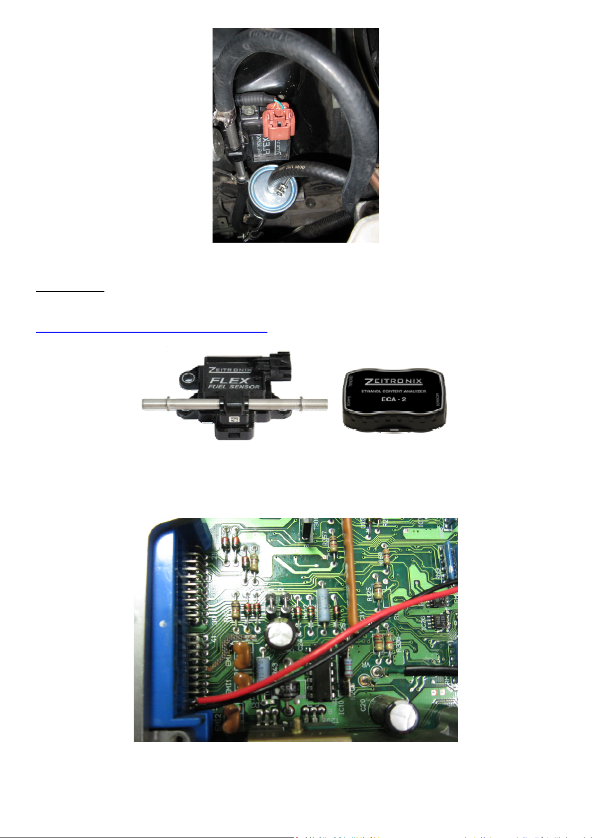
Image: Flex fuel sensor connected to fuel return line on S14 200SX
Zeitronix ECA 2
Zeitronix sell a content analyser in various packages, including with and without a display.
http://www.zeitronix.com/Products/ECA/ECA.shtml
The ECA-2 module includes wiring information. For wiring to your ECU Red is wired to the ECUs switched 12V power
line and Black is wired to the Ground line.
Image: HCR32 ECU with two end pins connected to flex converter power
Page 5 of 27
Page 6
Nissan ECU Connectors
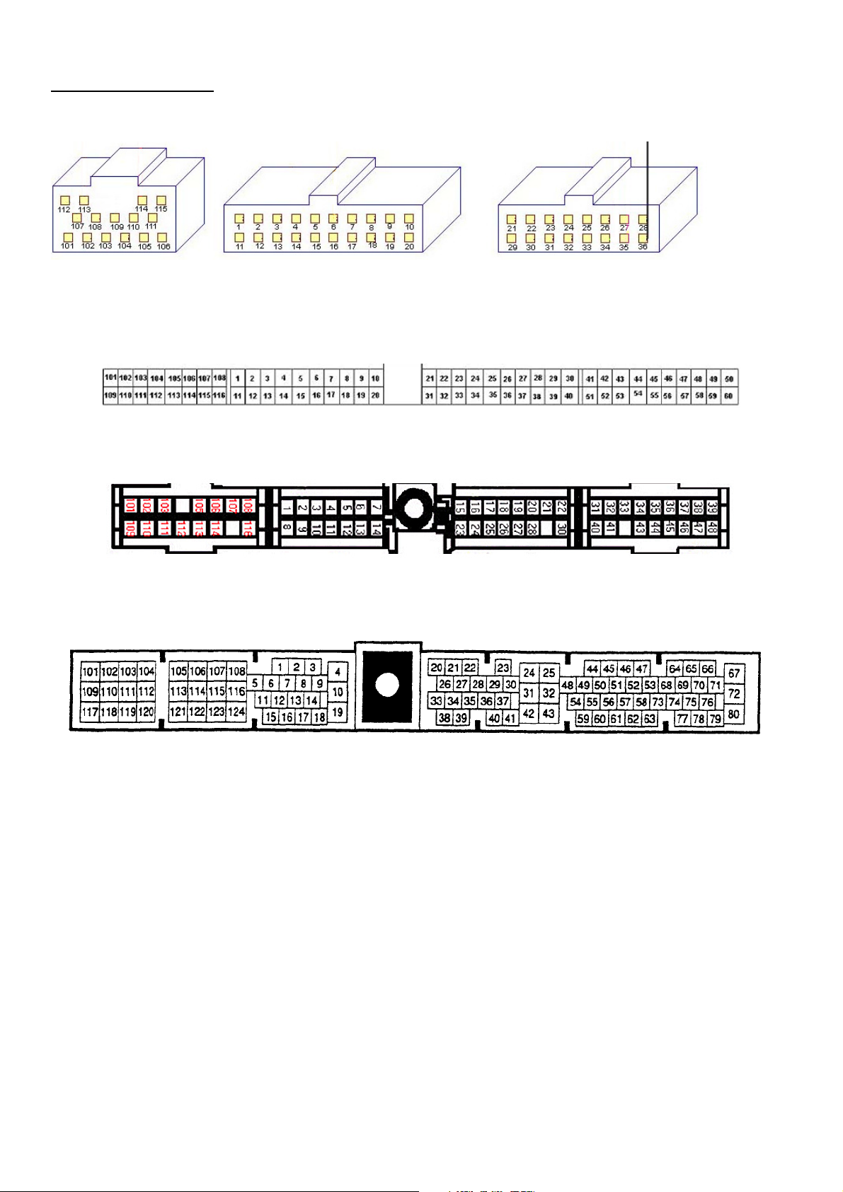
Z31 VG30 / R31 RB30 / VL RB30
Pin 27 is power, Pin 28 is ground
S13 CA18DET, S14 SR20DET, HCR32 RB20DET, BNR32 RB26DETT, Z32 VG30DET etc
Pin 49 is Power and pin 50 is Ground
S13/S14A/S15 SR20DET, P11 SR20DE, B13 SR20DE, S13 KA24DE etc
Pin 38 is Power and pin 39 is Ground
ER34/WC34 RB25DET
Pin 67 is Power and Pin 25 is ground
Page 6 of 27
Page 7
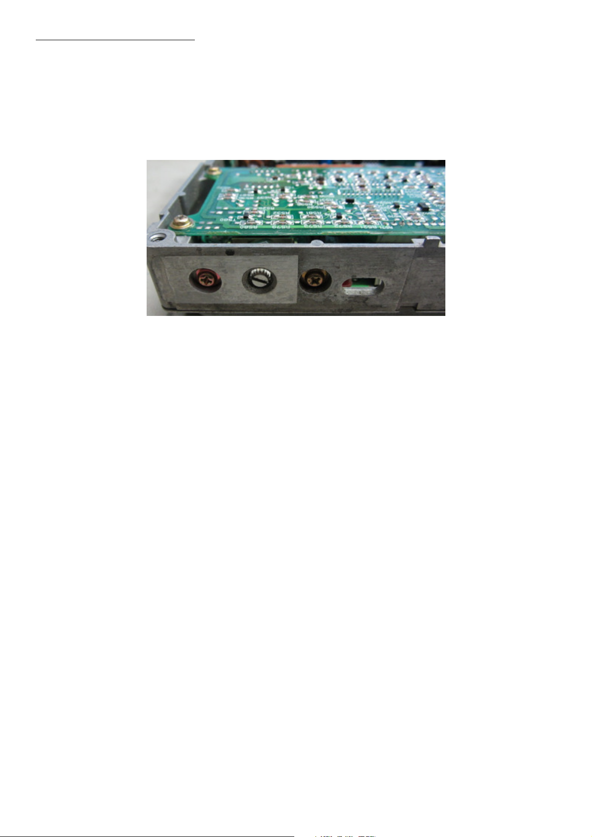
Diagnostic Potentiometer Removal
Earlier Nissan ECUs are fitted with a diagnostic potentiometer. This will require removal in order to fit the flex fuel
sensor line to the ECU.
Remove the diagnostic connector by unscrewing (or desoldering if surface mounted) and then fit the flex fuel sensor
line in place to the diagnostic input.
Image: HCR32 ECU diagnostic potentiometer
Page 7 of 27
Page 8
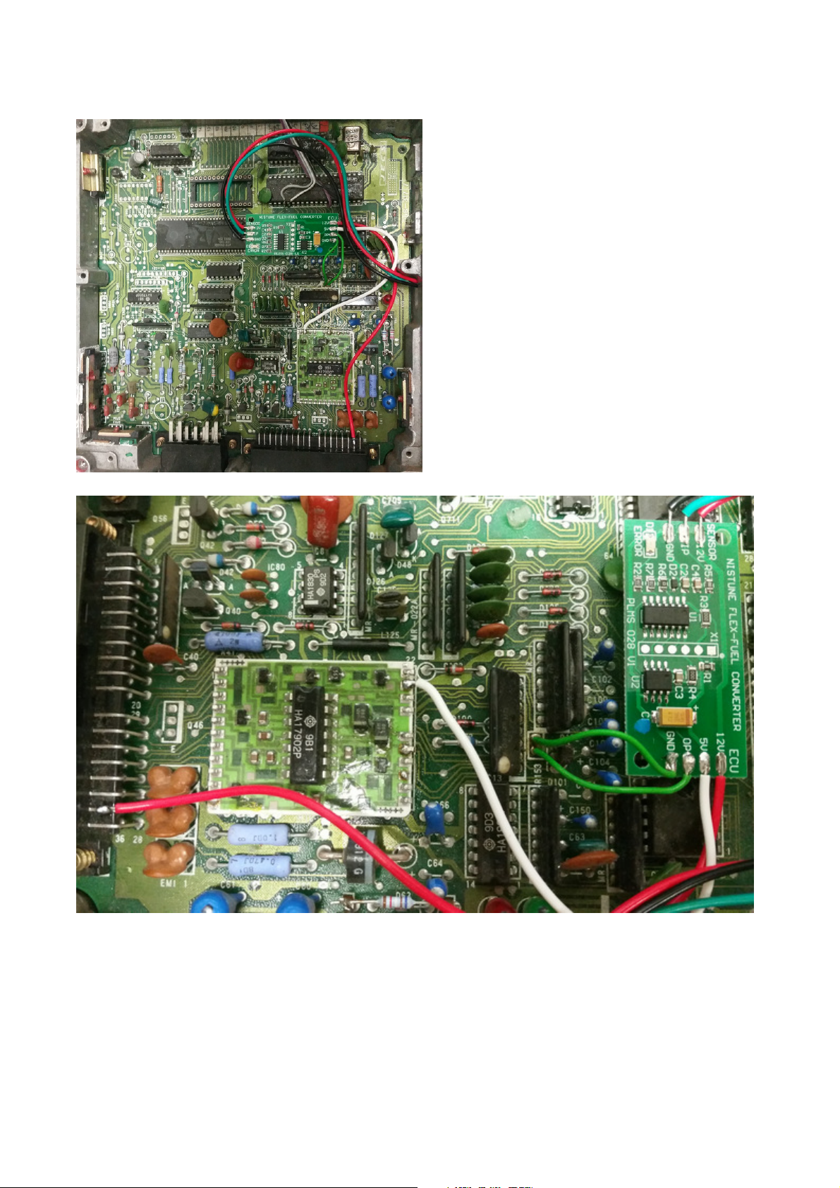
1. Z31 300ZX VG30 / VL RB30 / R31 RB30 ECU
- Cut both lines to the diagnostic connector
- Connect top line (GND) to Ground input on flex fuel converter
- Connect bottom line (Diag input) to OP on flex fuel converter
- Source 5V supply from OPAMP board Pin 21
- Source 12V supply from ECU power line on ECU connector pin 27
Page 8 of 27
Page 9
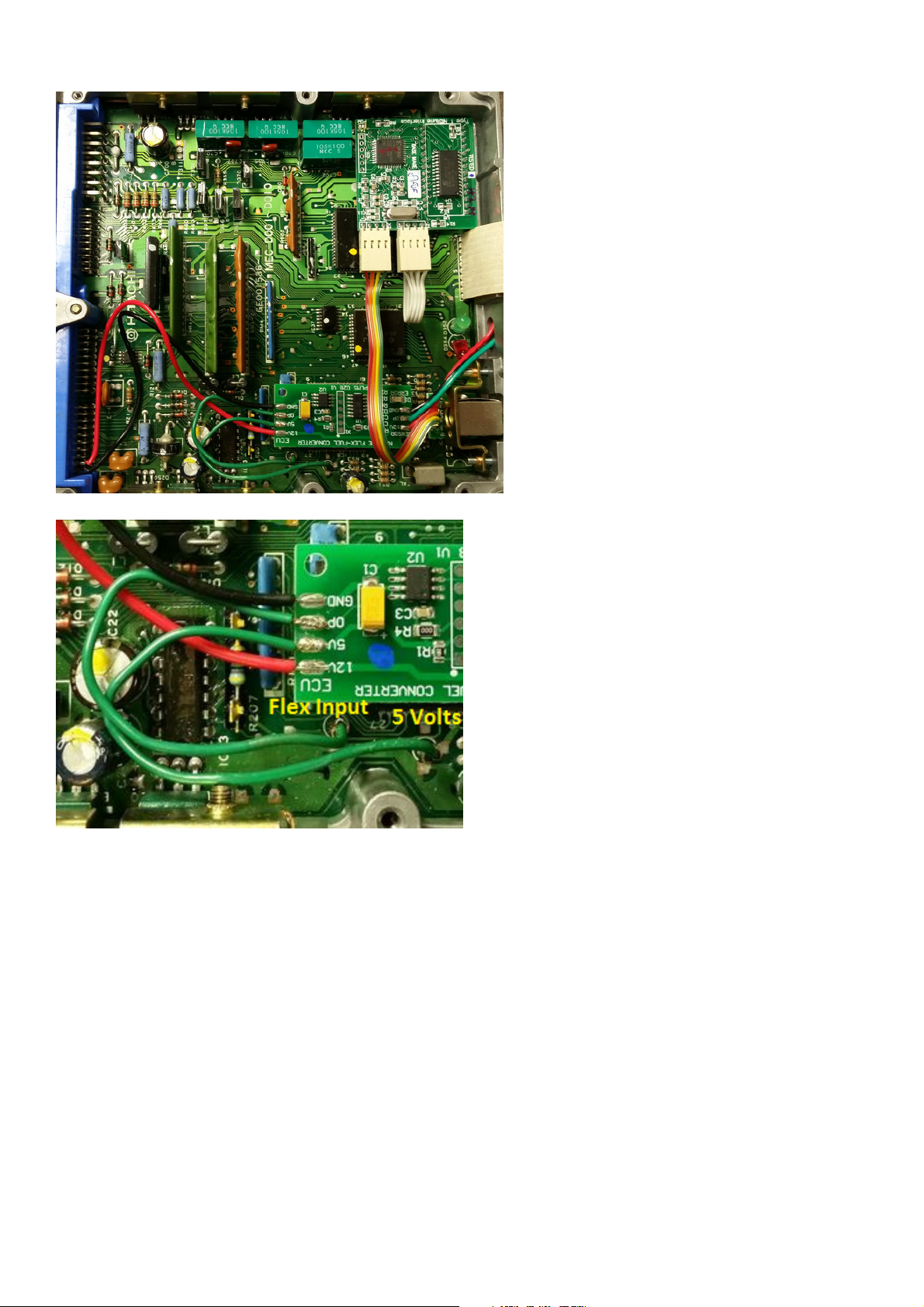
2. S13 CA18DET ECU
- Cut both diagnostic wires and connect LHS line to flex fuel sensor output line.
- For the Nistune Flex Converter, power the unit using the RHS line which provides 5 volts
Page 9 of 27
Page 10
-
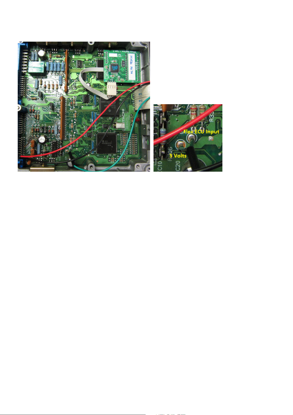
3. HCR32 RB20DET ECU
- Cut both diagnostic wires and connect RHS line to flex fuel sensor output line.
- For the Nistune Flex converter, power the unit using the 5 volt output from the ECU as marked
Page 10 of 27
Page 11
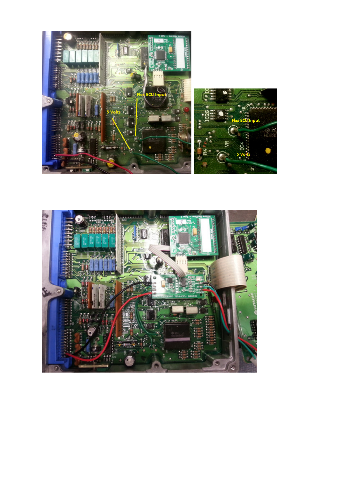
4. BNR32 RB26DETT ECU
- Cut both diagnostic wires and connect RHS line to flex fuel sensor output line.
- For the Nistune Flex converter, power the unit using the 5 volt output from the ECU as marked
Page 11 of 27
Page 12
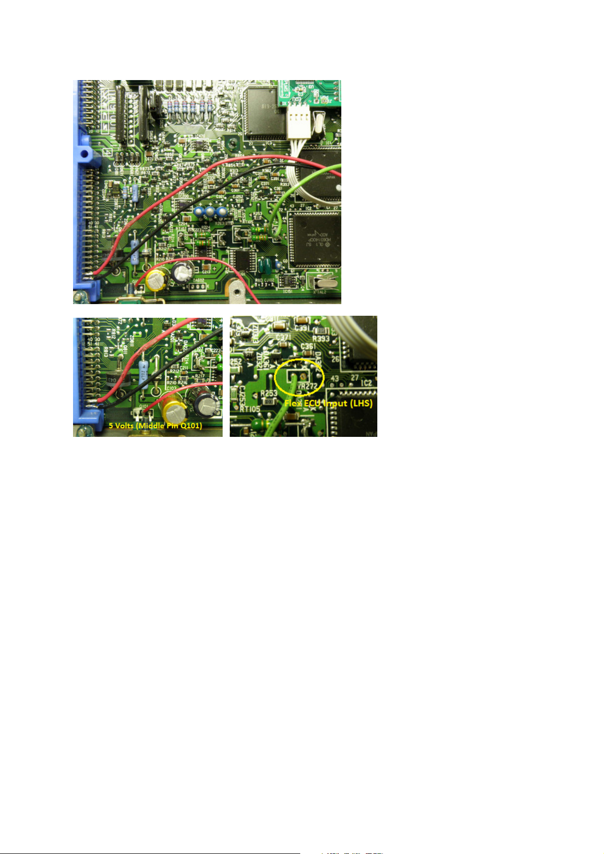
5. Z32 300ZX VG30DE/DETT ECU
- Cut both diagnostic wires and connect LHS line to flex fuel sensor output line.
For the Nistune Flex converter, power the unit using the 5 volt output from the Q101 middle pin as marked
Page 12 of 27
Page 13
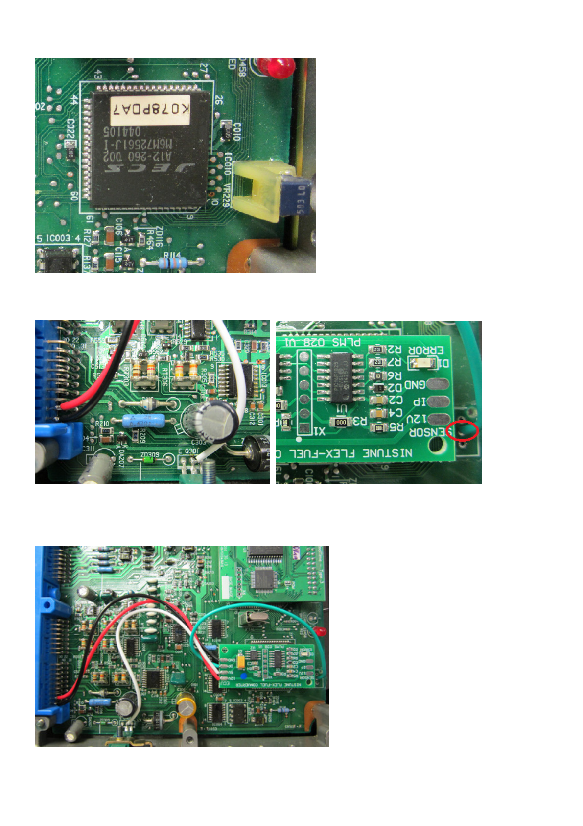
6. S13 SR20DE/SR20DET ECU
- Remove VR229 (variable resistor)
- Solder flex fuel input line as pictured to lower solder pad
- For the Nistune flex converter, power the unit using the 5 volt output from the middle pin as marked
Page 13 of 27
Page 14
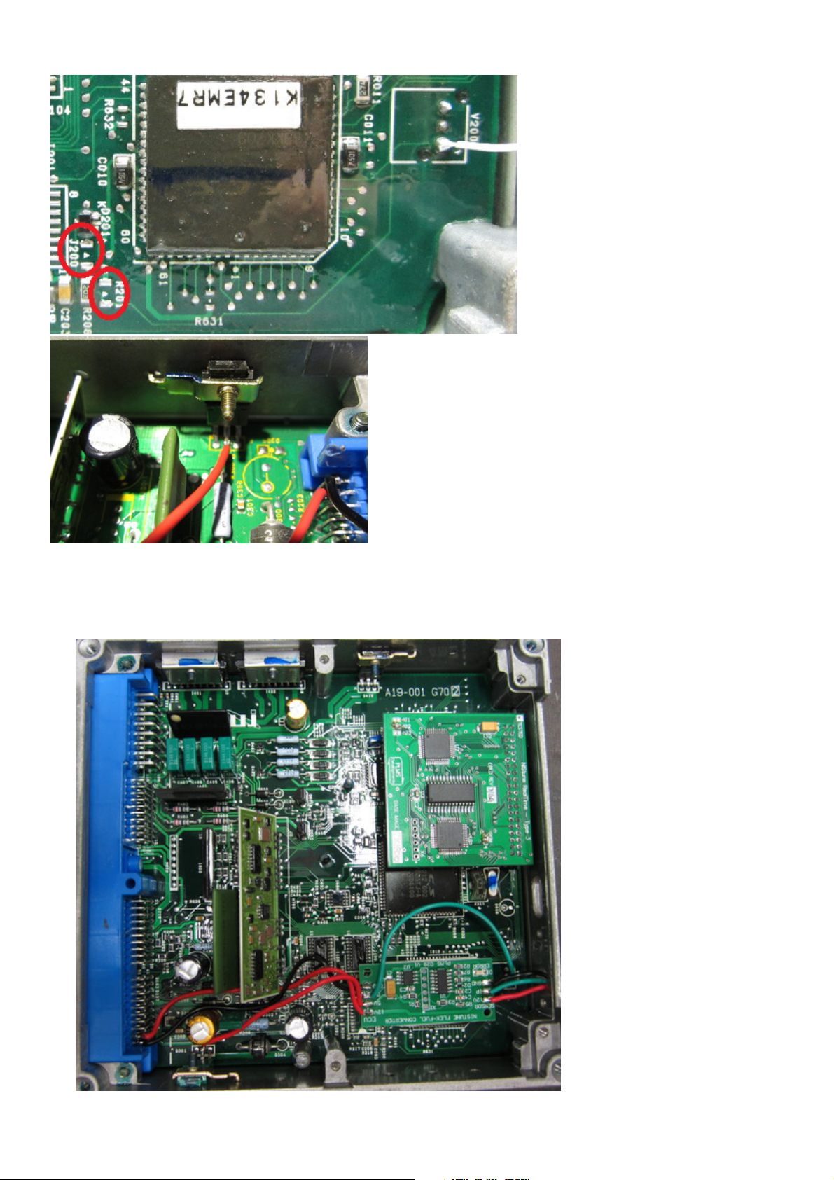
7. S14 SR20DET ECU
- Remove resistors J200 and J201
- Solder flex fuel input line as pictured to lower solder pad
- For the Nistune flex converter, power the unit using the 5 volt output from the middle pin as marked
Page 14 of 27
Page 15
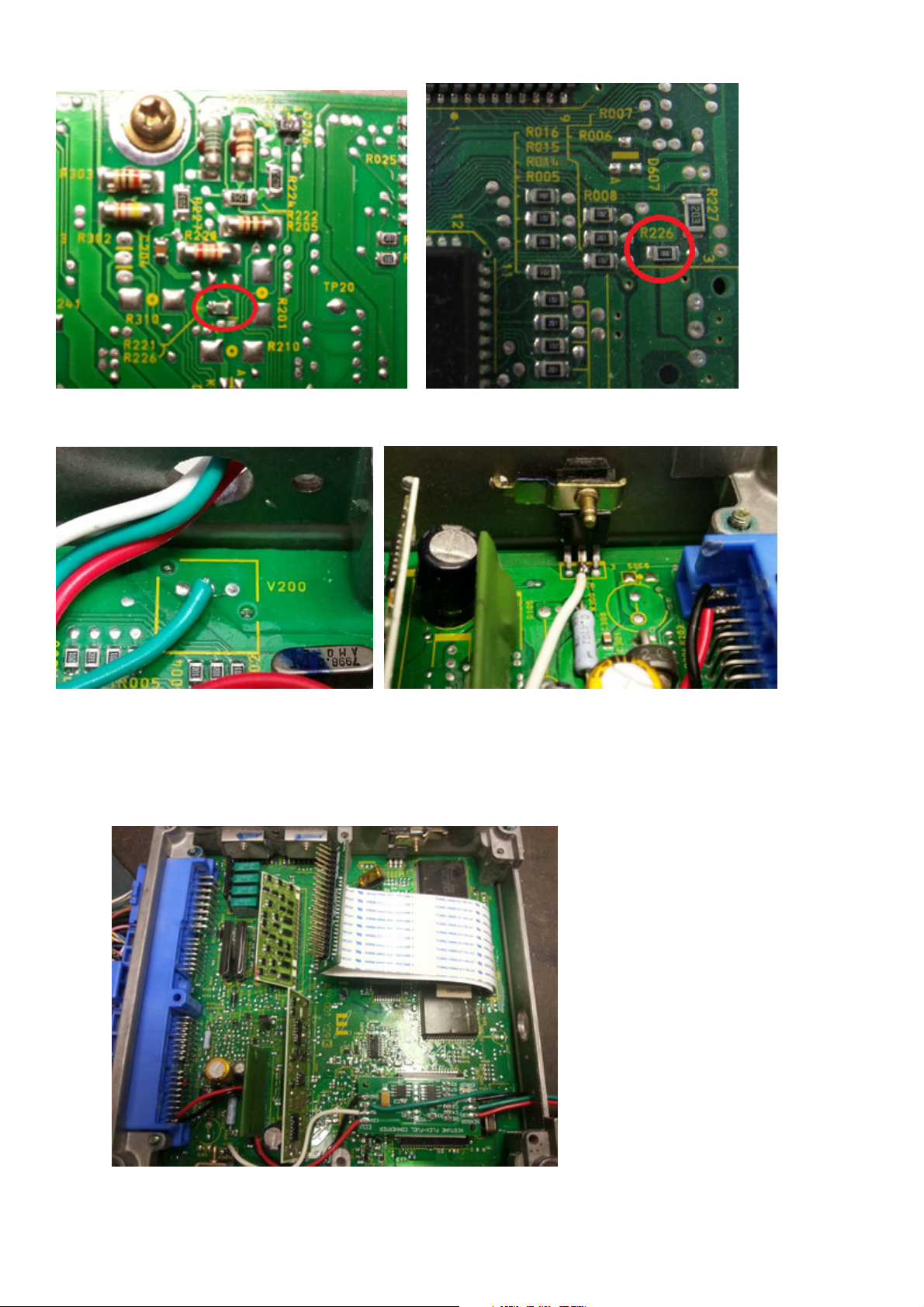
8. S13 SR20DET (Type R/X) / S14A SR20DET / S15 SR20DET / P11 SR20DE ECU
S13 (Type X) // S14A/P11 ECU rear of ECU. S15 next to diagnostic connector
- Removed marked resistor R226
- Solder flex fuel input line as pictured to middle solder pad of V200
- For the Nistune flex converter, power the unit using the 5 volt output from the middle pin of the voltage
regulator as shown
Page 15 of 27
Page 16
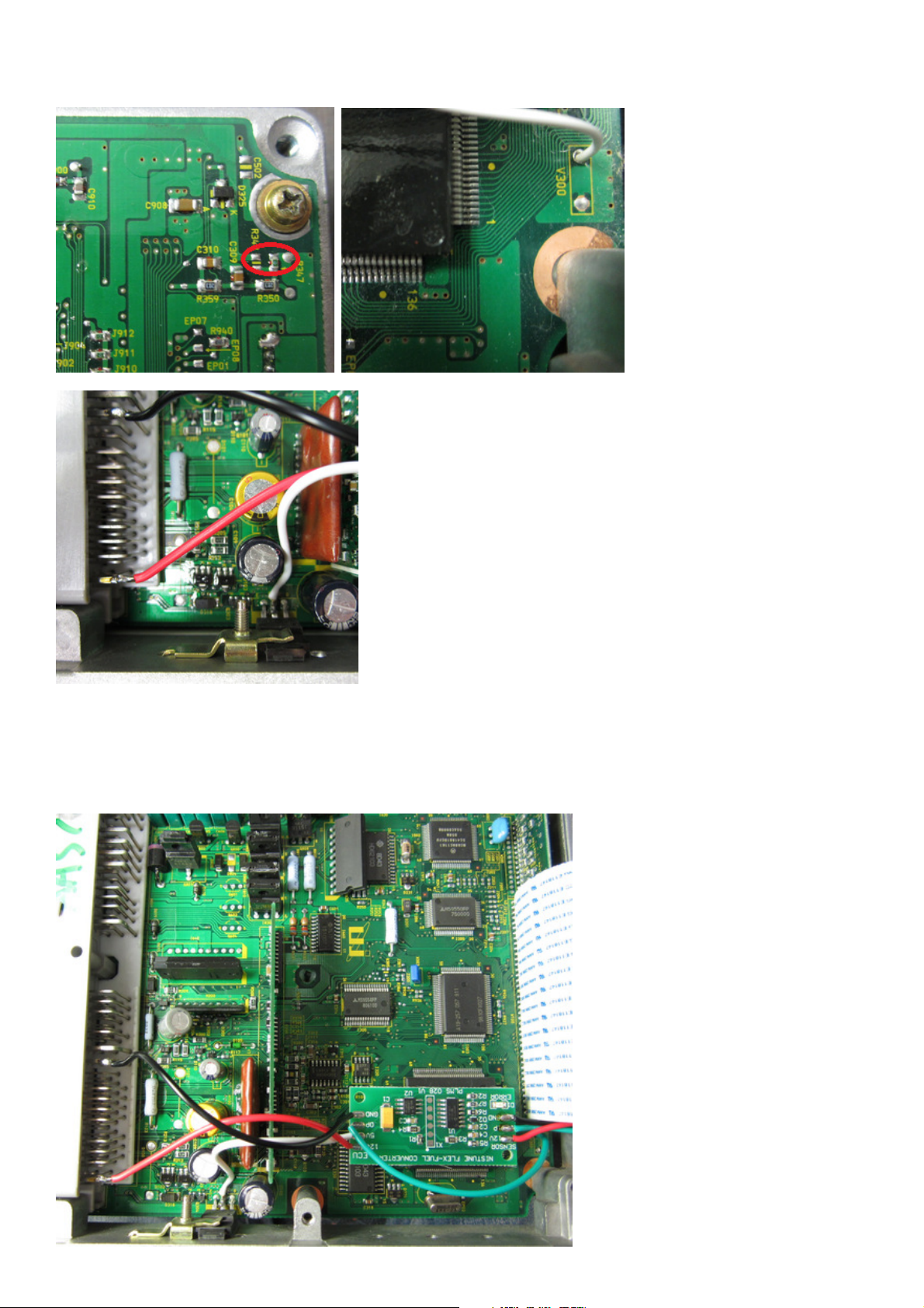
9. ER34 / WC34 RB25DET / Y33 VQ30DE ECU
- Remove resistor R347
- Solder flex cable as marked to LHS pad of V300
- For the Nistune flex converter, power the unit using the 5 volt output from the middle pin of the voltage
regulator as shown
Page 16 of 27
Page 17
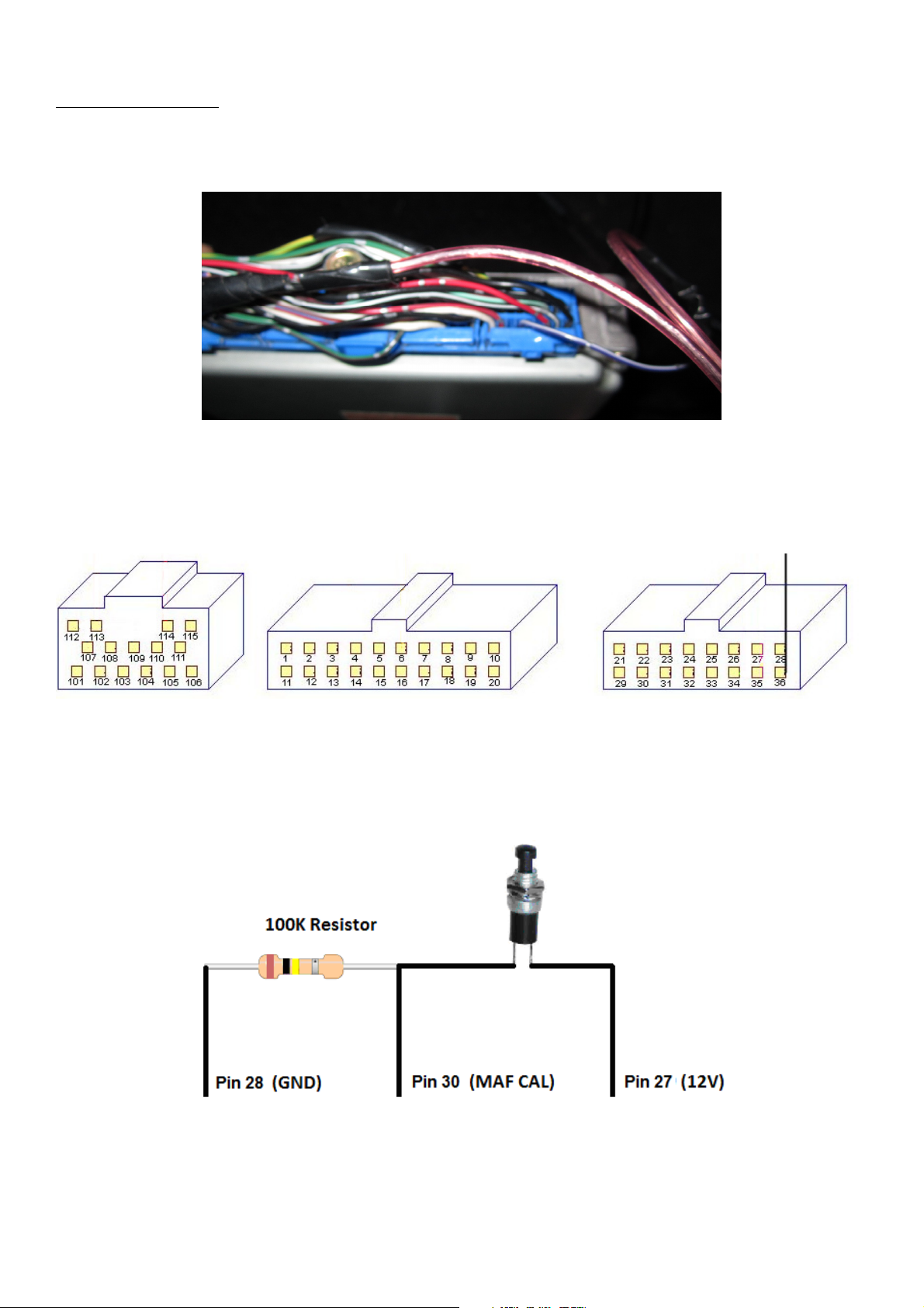
Launch Control Operation
External Switch Trigger
Launch control can be triggered either using the speed input, or using an external switch. Disconnect the Power
Steering line from the ECU and connect directly to a clutch switch to trigger the launch control externally.
Image: Wiring external trigger between ground and power steering line
Z31 VG30 / R31 RB30 / VL RB30
Pin 28 - Ground
Pin 27 - 12V power
RB30
Pin 30 - MAF calibration signal (RB30 only). Wire as per S13 CA18DET with switch
VG30
Pin 15 - Fuel temp input (VG30 only) wire this end switch as above, and other side of switch to Pin 28 (GND)
Page 18
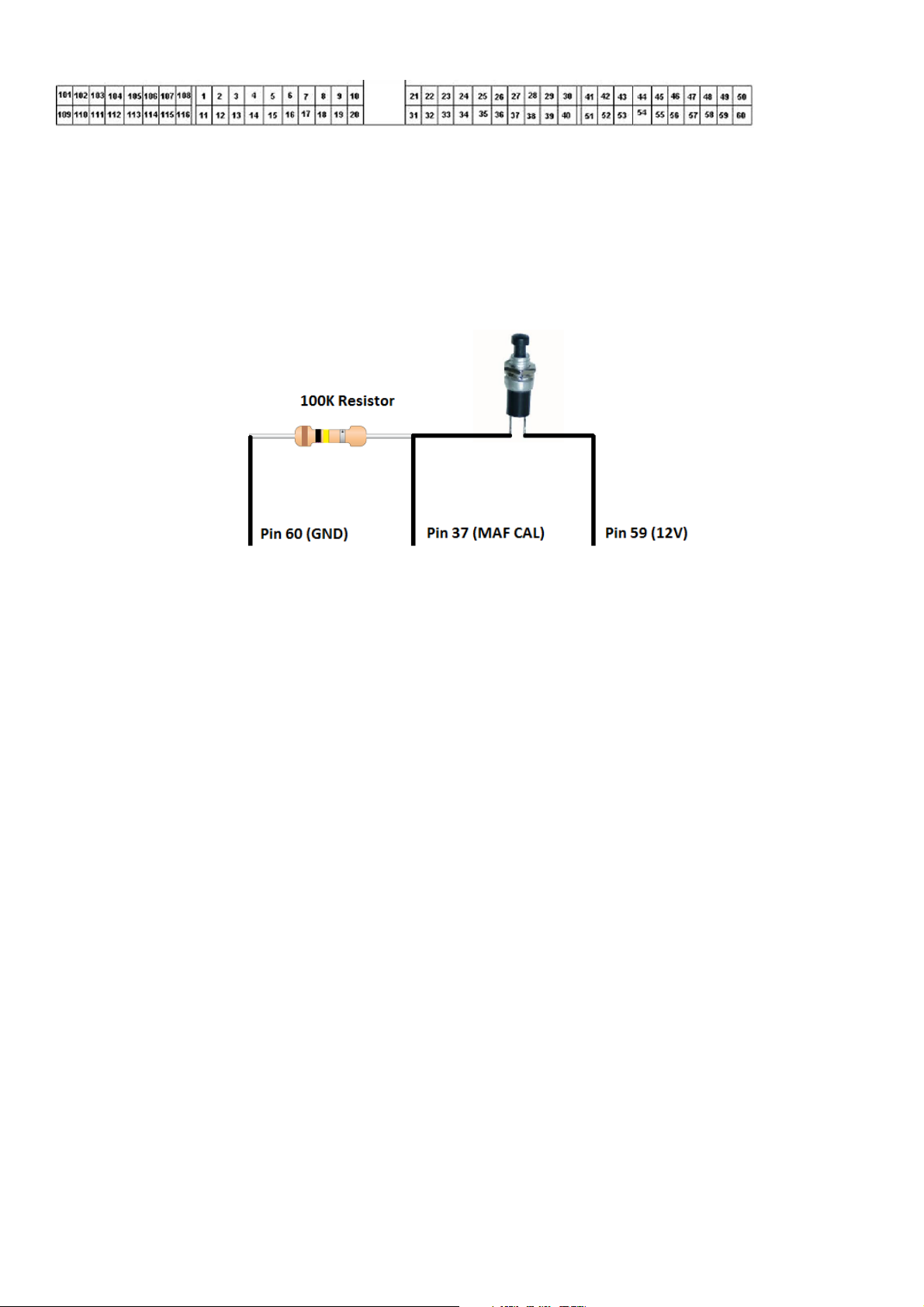
S13 CA18DET
Pin 37 - MAF Calibration signal (non-cat models have a line, cat models will need this pin inserted)
Pin 60 - Ground
Pin 49 - 12V power
To reuse the MAF calibration signal, hold down the line using around 100K ohm resistor and use a pull up to 12V via
clutch switch or similar. We use pull up here because of capacitance held on the line.
Page 18 of 27
Page 19
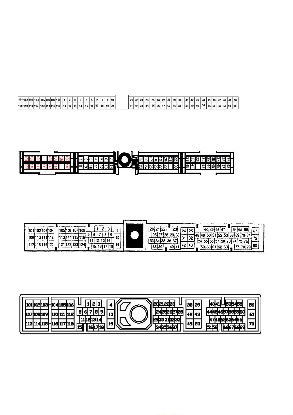
Other ECUs
Cut the power steering line at the ECU and connect to a shielded cable with shield connected to ground. The switch
can be operated by clutch or otherwise. A momentary push of the switch will enable/disable the launch control
output.
S14 SR20DET, HCR32 RB20, BNR32 RB26, Z32 VG30 etc
Pin 19 – HCR32 / BNR32: Power steering switch trigger
Pin 34 - S14 SR20DET/Z32 VG30: Power steering switch trigger
Pin 60 – Ground
S13/S14A/S15 SR20DET etc
Pin 43 – S13/S14A/S15/P11: Power steering switch trigger
Pin 39 - Ground
ER34/WC34 RB25DET
Pin 26 – Power steering switch trigger
Pin 25 - Ground
S14 KA24DE/B14 SR20DE
Pin 25 – Power steering switch trigger
Pin 32 - Ground
Page 19 of 27
Page 20

Variable Cam Timing Output
Special firmware updates have been made for HCR32 RB20DET and A31 RB20DET ECUs for triggering VCT output
using existing ECU outputs when these ECUs are used with RB25DET engines. There are three flavours of firmware
depending on ECU and if air conditioning is required
Page 20 of 27
Page 21
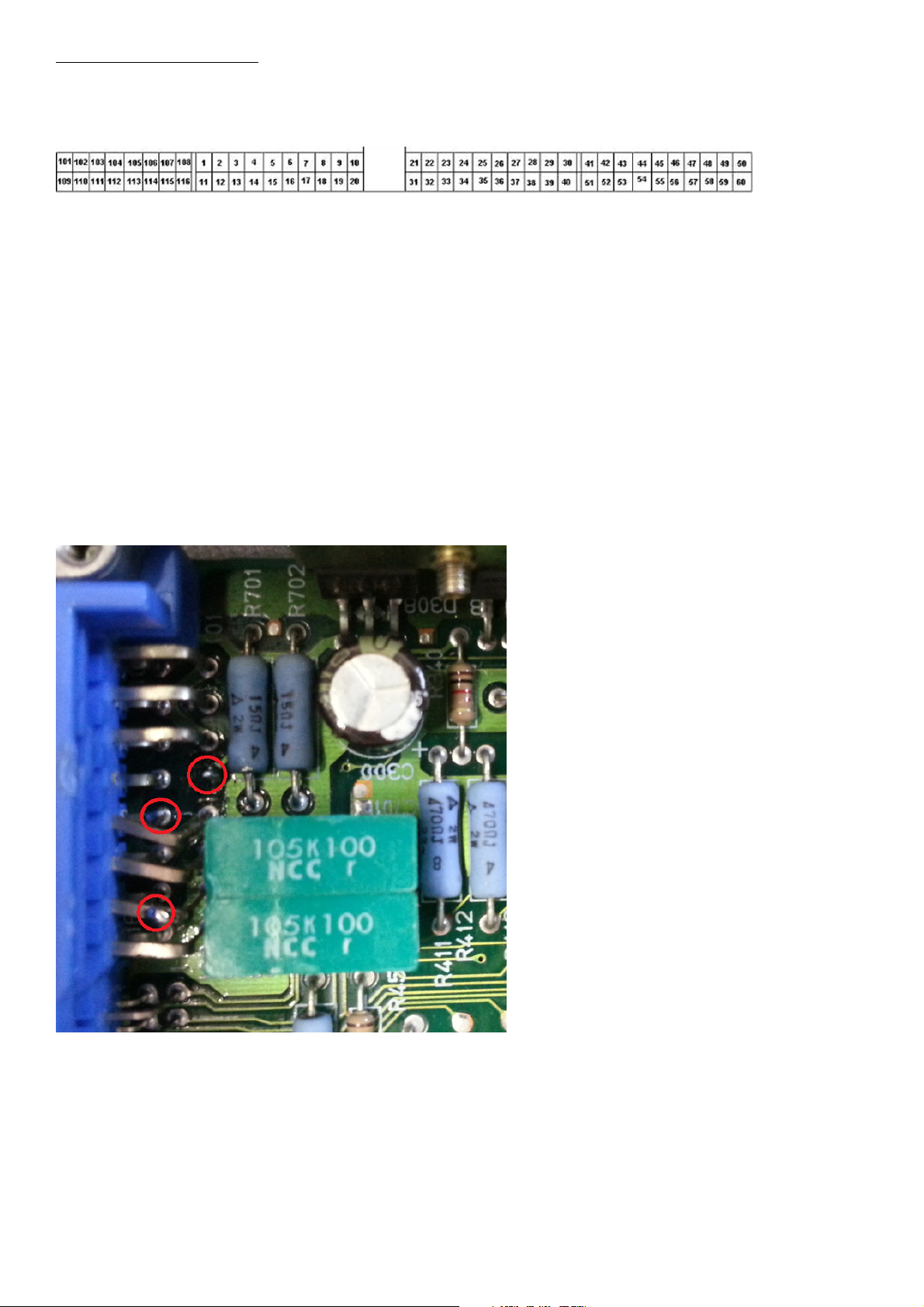
RB25DET using RB20DET ECU
Fuel Pump Idle Control output (23710-11UXX/04UXX R32 ECU)
1. Remove Fuel Pump Control idle output.
Pin 104 - Controls idle fuel pump voltage to Fuel Pump Control Module (FPCM). When installing an aftermarket high
flow fuel pump, it should be controlled directly from the fuel pump relay rather than FPCM.
This ECU output is normally used to vary fuel pump idle speed with the factory fuel pump. This pin will no longer be
used and the output from the ECU will control the VCT
HCR32_FOR_RB25_11U0F_MT_TPS_VCT_VFCOUT_v5_FP.ENT
1. Cut pin 104 from ECU connector to pad on board, leaving about 2mm exposed from board.
2. Slightly push other pins to access pin 113
Add solder to pin 104 (from ECU board)
Add solder to pin 113 (VCT from connector)
Add solder to pin 107 (top ground pin)
3. Source BD679 Darlington Transistor (SOT-32 package) and pre-tin (solder) ends of transistor
Available from Farnell (Element-14) and other electronics specialists
4. Solder transistor to ECU with shiny shielded side facing upwards
Pin 1 (Base) - Solders to pin 104 coming from the circuit board
Pin 2 (Collector) - Solders to pin 113 coming from ECU plug (VCT output)
Pin 3 (Emitter) - Solders to pin 107
Page 21 of 27
Page 22
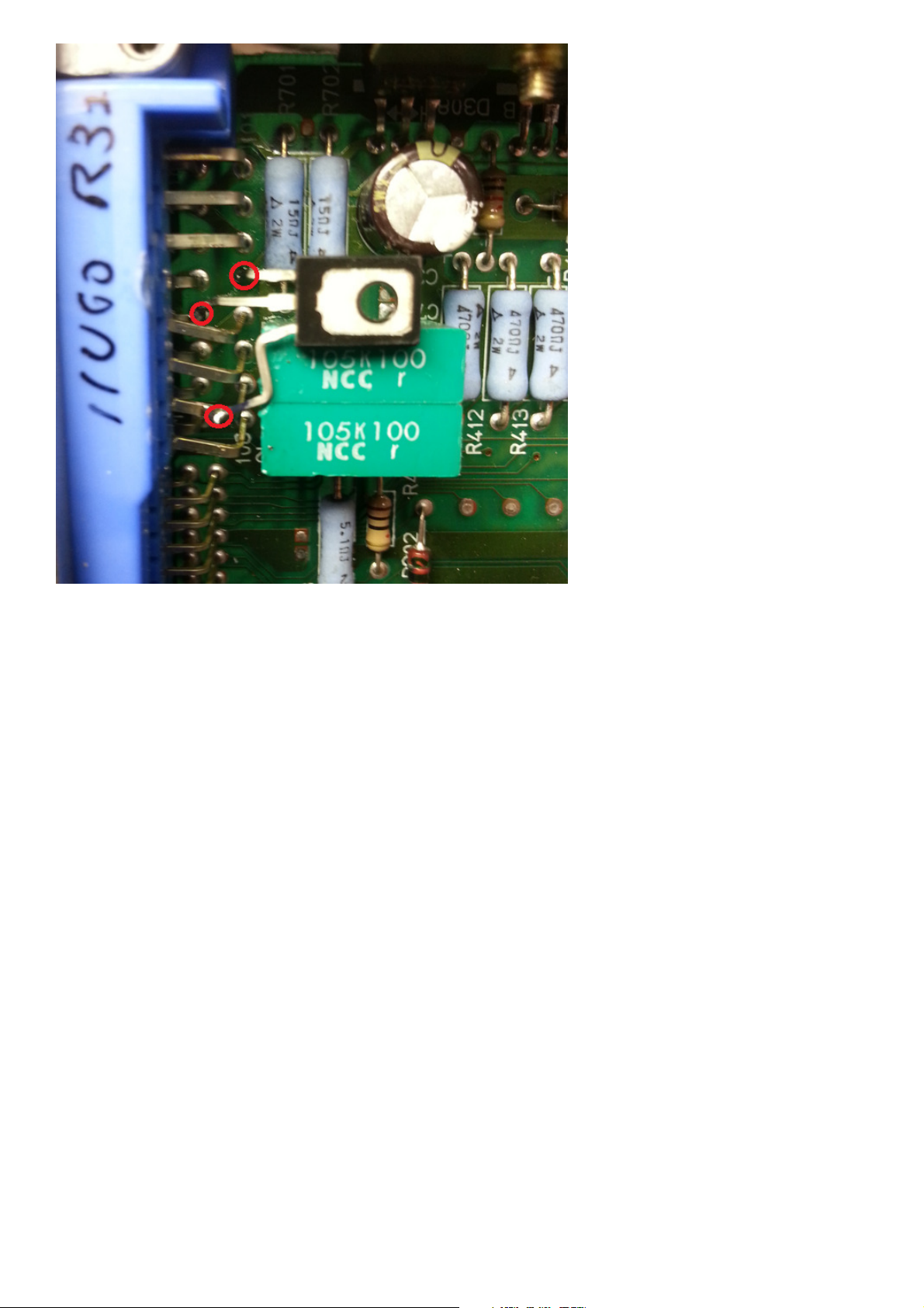
1.5 Vehicle will operate as normal with VCT operation now allowed, and Fuel pump idle disabled.
Page 22 of 27
Page 23
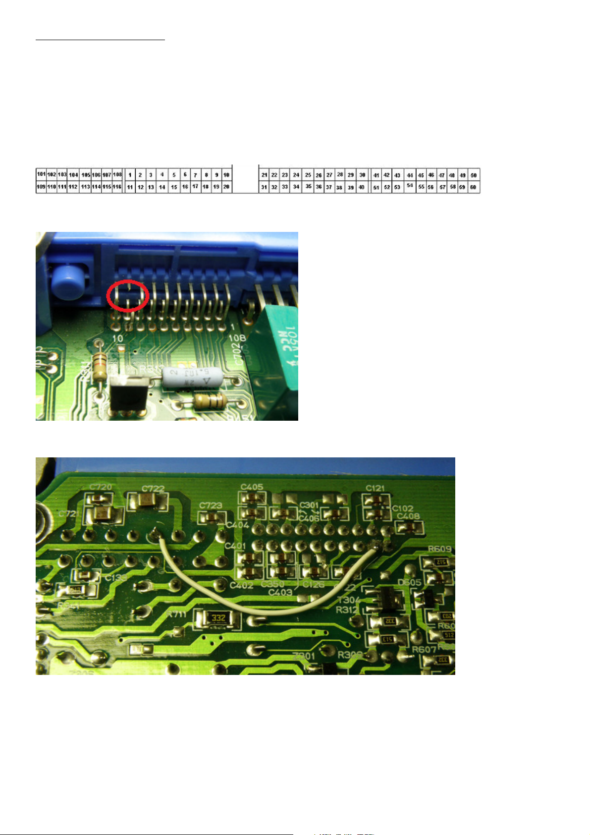
RB25DET using RB20DET ECU
Air Conditioning output (23710-11UXX R32 ECU)
1. Remove RB25 Air conditioning output
A31: HCR32_FOR_RB25_11U00_74L00_MT_FP_TPS_VCT_ACOUT_v5.ent
R32: HCR32_FOR_RB25_11U00_MT_FP_TPS_VCT_ACOUT_v5.ent
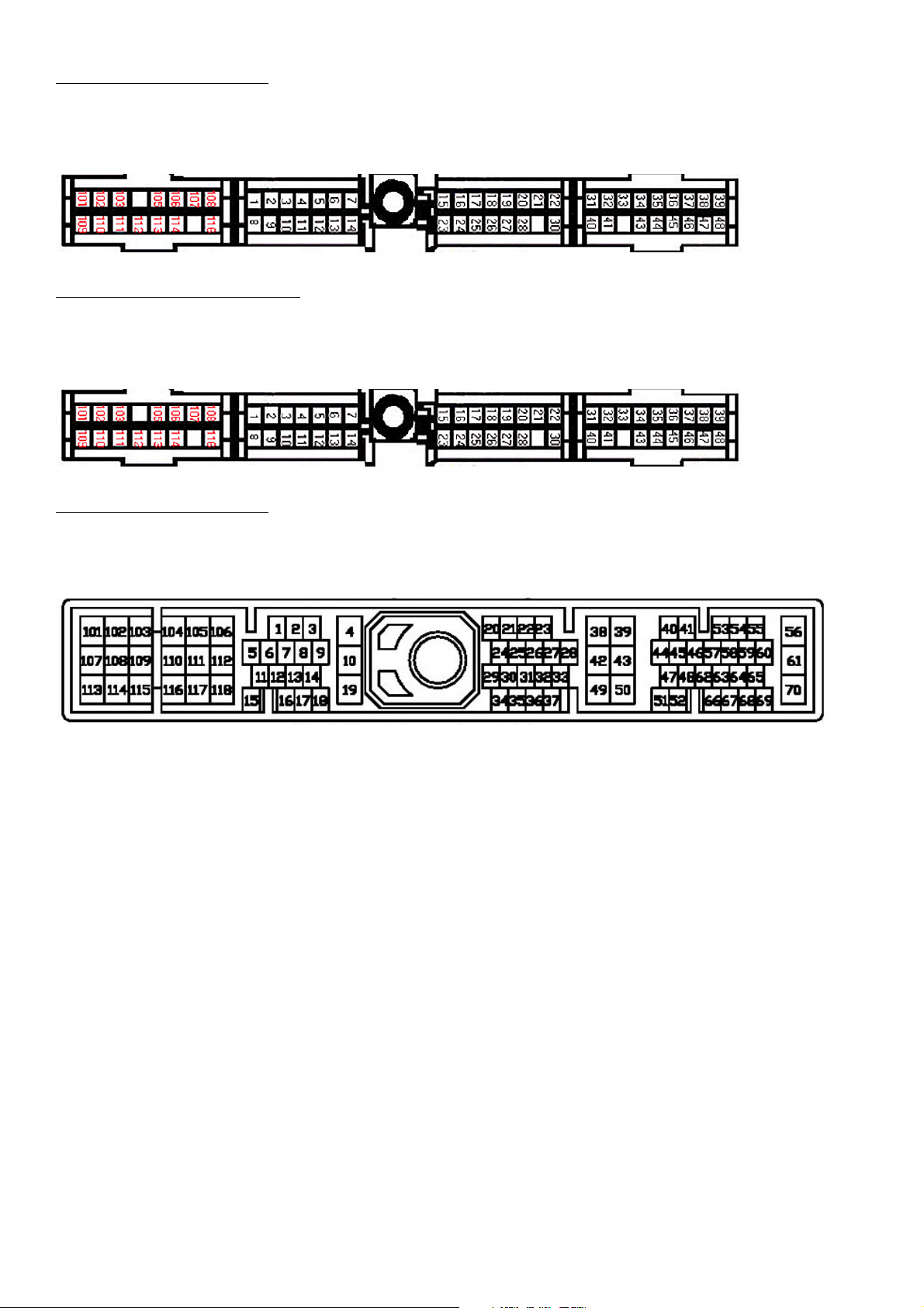
Pin 113 - ECR33 RB25 - VCT output solenoid
Pin 9 - Air conditioner relay
2. Cut pin 9 from ECU
3. Solder pin 9 to pin 113
Page 23 of 27
Page 24
RB25DET using RB20DET ECU
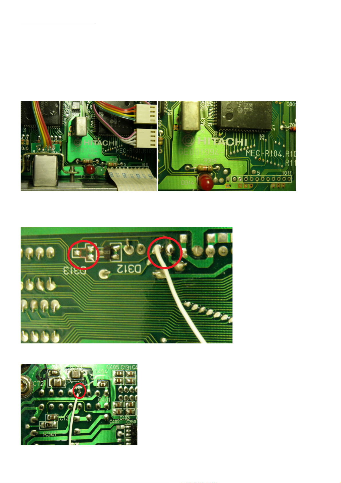
Spare LED output (23710-04UXX R32 ECU, 23710-74Lxx/79Lxx A31 Cefiro ECU)
1. Utilise spare GREEN diagnostic LED (Available A31 and early R32 ECUs only)
A31: HCR32_FOR_RB25_11U00_74L00_MT_FP_TPS_VCT_LEDOUT_v5.ent
R32: HCR32_FOR_RB25_11U00_MT_FP_TPS_VCT_LEDOUT_v5.ent
HCR32 ECUs must be part number 23710-04UXX or MEC-R1XX which have the placement for the second LED on the
circuit board
2. Remove the GREEN LED (if fitted and supporting diode on reverse side of the ECU)
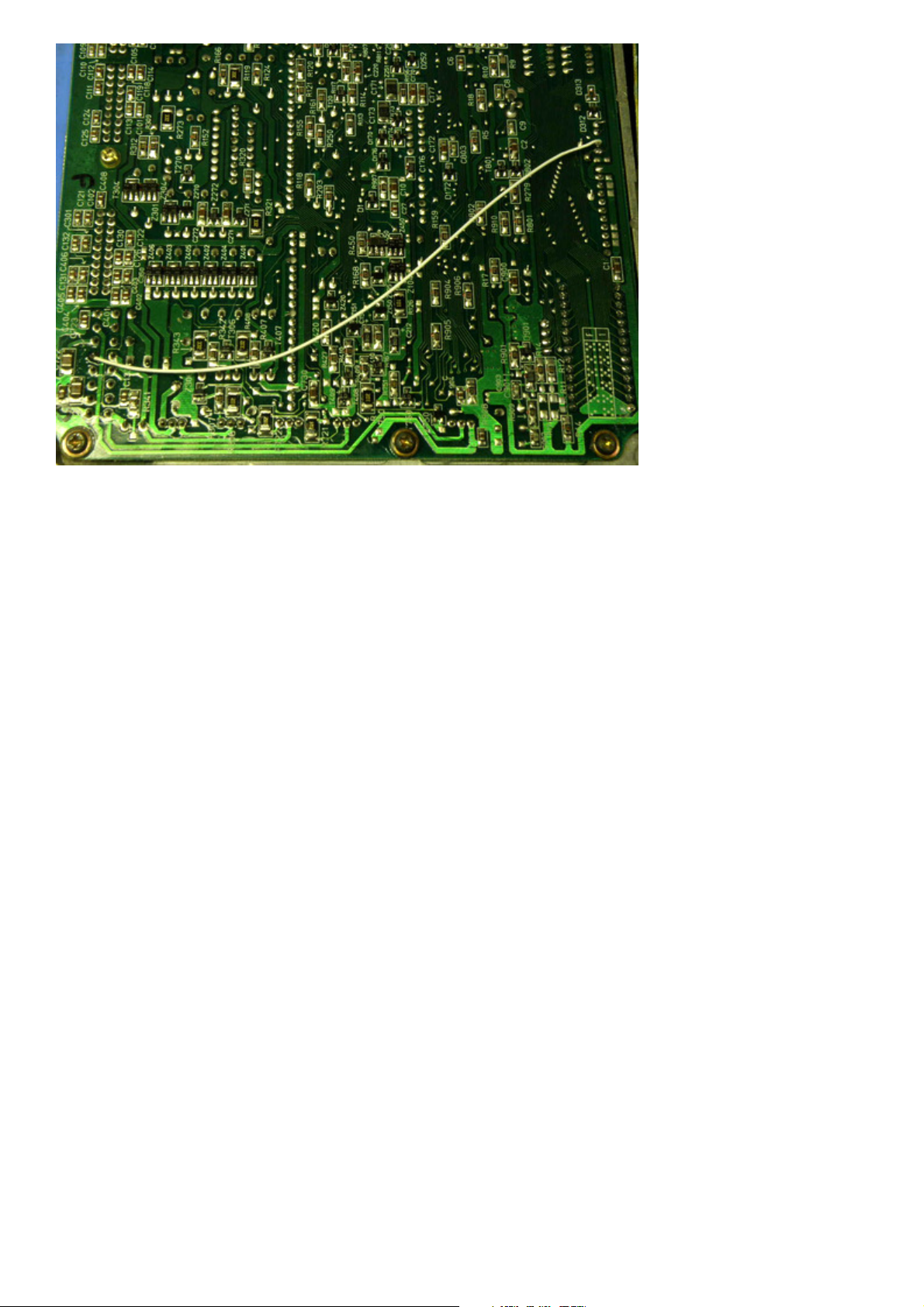
3. Solder the VCT line where shown (where the GREEN LED was fitted)
4. Solder to pin 113 as pictured
5. Fitment should look as pictured
Page 24 of 27
Page 25
Page 25 of 27
Page 26
SR20VE using P11 SR20DE ECU
PIN 114 – Evaporative Canister Purge Solenoid (wire to pin 105 inside the ECU)
Notes: SR20VE Pin 105 runs to VCT solenoid as negative trigger
SR20VE using B13/S13 SR20DE ECU
PIN102 - Canister Purge Solenoid (wire to pin 105 inside the ECU)
Notes: SR20VE Pin 105 runs to VCT solenoid as negative trigger
SR20VE using B14 SR20DE ECU
PIN103 - EGR Canister Purge Solenoid (wire EGR solenoid lines in engine bay to SR20VE VCT solenoid)
Notes: SR20VE VCT Pin works as negative trigger
Page 26 of 27
Page 27

IMPORTANT INFORMATION
Nistune Developments has performed necessary measures to ensure that the Nistune software and boards are built to high standards. However Nistune
Developments will not be held responsible for any damages which may arise from the use or misuse of this product. By using this product you agree to the
following terms:
IMPORTANT - READ CAREFULLY: This License Agreement is a legal agreement between you and Nistune Developments for the software product Nistune. The
software product includes computer software, the media belonging to it, printed materials and electronic documentation. With installing, copying or any other
use of this software product, you agree to the terms of this agreement. If you do not agree to the terms of this agreement, you are not allowed to use or copy
this software product. Further you are required to remove the software product from your computer.
1. GRANT OF LICENSE
You are granted a license as a single user of this software. You are allowed to install and use this software freely. However you may not install this software for
another user and may only make a single backup. The software may be installed on multiple machines belonging to the single user whilst those machines remain
property of that single user. Regardless of other rights, the author of the software product is allowed to terminate this license agreement if you offend against
the determinations and conditions of this agreement. If so, you will have to remove all copies of the Software and its components.
2. COPYRIGHT
You may not copy, modify or distribute the Software except under the terms given in this licence document. You may not sublicense the Software or in any way
place it under any other licence than this one. The Software is protected by copyright laws of the Australia and international copyright treaties. Copyright and
property right of the software product are set to the authors of the software. You do not purchase any rights on the Software except those called in this license
agreement.
3. TERM
Your license is effective upon your acceptance of this agreement and installing the Licensed Product. You may terminate it at any time by destroying the
Licensed Product together with all copies. It will also terminate upon conditions set forth elsewhere in this Agreement or if you fail to comply with any term or
condition of this Agreement. You agree upon such termination to destroy all copies of the Licensed Product in any form in your possession or under your control.
4. DECOMPILING
You agree not to reverse engineer the Software, change, spilt, decompile, disassemble or translate the Software in part or in whole, without prior written
consent from Nistune Developments.
5. UPDATES
Nistune Developments may, from time to time, revise or update the product. In so doing, Nistune Developments incurs no obligation to furnish such revision or
updates to you.
6. WARRANTY
The author of this Software has verified as best as possible to make sure the main features and functions work as described while normal usage on compatible
equipment. Due to the complexity of computer software, we cannot guarantee that the software or documents does not contain errors or works without
intermissions on any equipment and software configuration. The Software and the documentation are distributed in the state as present and you accept all risks
with the usage. The author does not take any warranty either express or implied to the software or the documentation about its fitness generally or its
qualification for special purposes except those warranties that have to be applied through obliged laws and that cannot be excluded. You know that you have to
regularly backup your data and that you have to affect additional security provisions if a software error is supposed. The entire risk as to the quality and
performance of the Software is with you. Should the Software prove defective, you assume the cost of all necessary servicing, repair, legal defence, punishment,
damages or correction.
NISTUNE DEVELOPMENTS OFFERS NO WARRANTY OF PERFORMANCE, EXPRESS OR IMPLIED, WITH REGARD TO THE LICENSED PRODUCT AND ALL
ACCOMPANYING MATERIALS. NISTUNE DEVELOPMENTS FURTHER DISCLAIMS ALL OTHER WARRANTIES, EXPRESS OR IMPLIED, INCLUDING BUT NOT LIMITED TO
THE IMPLIED WARRANTIES OF MERCHANTABILITY AND FITNESS FOR A PARTICULAR PURPOSE, WITH REGARD TO THE LICENSED PRODUCT AND ALL
ACCOMPANYING MATERIALS.
7. DISCLAIMER OF LIABILITY
NO LIABILITY FOR CONSEQUENTIAL DAMAGES. IN NO EVENT SHALL NISTUNE DEVELOPMENTS BE LIABLE FOR ANY SPECIAL, INCIDENTAL, INDIRECT, OR
CONSEQUENTIAL DAMAGES WHATSOEVER (INCLUDING, WITHOUT LIMITATION, DAMAGES FOR LOSS OF BUSINESS PROFITS, BUSINESS INTERRUPTION, LOSS OF
BUSINESS INFORMATION, OR ANY OTHER PECUNIARY LOSS) ARISING OUT OF THE USE OF OR INABILITY TO USE THE NISTUNE PRODUCT, EVEN IF NISTUNE
DEVELOPMENTS HAS BEEN ADVISED OF THE POSSIBILITY OF SUCH DAMAGES.
IN NO EVENT WILL NISTUNE DEVELOPMENTS BE LIABLE FOR ANY COMPUTER DAMAGE, VEHICLE DAMAGE, PERSONAL INJURY, DEATH, FINES, LAWSUITS,
PROSECUTION, LOST PROFITS, LOST DATA, INCORRECT DATA, ENVIRONMENTAL DAMAGE, GOVERNMENT, LAW AND REGULATORY VIOLATIONS OR ANY OTHER
INCIDENTAL OR CONSEQUENTIAL DAMAGES THAT RESULT FROM USE OR INABILITY TO USE THE NISTUNE PRODUCT.
THE NISTUNE PRODUCT IS NOT INTENDED FOR USE IN OPERATION OF MOTOR VEHICLES AND/OR MACHINES WHERE THE USE, FAILURE OR MISUSE OF THE
SOFTWARE COULD LEAD TO DEATH, PERSONAL INJURY OR PHYSICAL OR ENVIRONMENTAL DAMAGE AND OR VIOLATE ANY ENVIRONMENTAL, SAFETY,
TRANSPORTATION OR OTHER LAWS OR REGULATIONS. IT IS THE USER’S RESPONSIBILITY TO OBTAIN ANY CERTIFICATION, RECERTIFICATION OR NEW
CLASSIFICATIONS PERTAINING TO USE OF THE NISTUNE PRODUCT. WHERE THE LIMITATION OF LIABILITY FOR INCIDENTAL OR CONSEQUENTIAL DAMAGES IS
NOT ALLOWED, NISTUNE DEVELOPMENTS TOTAL LIABLITY TO YOU FOR ALL DAMAGES WILL NOT EXCEED $1.00 AUD. NISTUNE PRODUCT INSTALLATION
REMAINS THE SOLE RESPONSIBILITY OF THE VEHICLE OWNER.
8. GENERAL
This License is personal between you and Nistune Developments. It is not transferable and any attempt by you to rent, lease, sublicense, assign or transfer any
of the rights, duties or obligations hereunder, except as provided in Section 2, above, is void. This Agreement and the conduct of the parties hereto shall be
governed by the laws of the Australia.
YOU ACKNOWLEDGE THAT YOU HAVE READ THIS AGREEMENT, UNDERSTAND IT AND AGREE TO BE BOUND BY ITS TERMS AND CONDITIONS. YOU FURTHER
AGREE THAT IT IS THE COMPLETE AND EXCLUSIVE STATEMENT OF THE AGREEMENT BETWEEN YOU AND NISTUNE DEVELOPMENTS WHICH SUPERSEDES ANY
PROPOSAL OR PRIOR AGREEMENT, ORAL OR WRITTEN, AND ANY OTHER COMMUNICATIONS BETWEEN YOU AND NISTUNE DEVELOPMENTS RELATING TO THE
PRODUCT.
Page 27 of 27
 Loading...