

Page 1
NISTA DEVICES GmbH 2013 © All Rights Reserved
1
Analog Door
Phones
Door Access Control with analog telephony interface
Installation and Programming Manual
Document Release: 1.15
Release 1.17_U4
April 2015
Analog Door Phone
Installation and Programming Manual
Door Access Control with Analog Telephony Interface
Page 2
NISTA DEVICES GmbH 2013 © All Rights Reserved
2
NOTICE
This document refers to the Nista Devices GmbH Door Access Control devices with analog telephony interface.
Additional copies of this manual may be obtained from Nista Devices GmbH. Reproduction of this manual or parts
thereof without written permission from Nista Devices GmbH is strictly prohibited.
Nista Devices GmbH reserves the right to modify the hardware and software described herein without prior notice.
However, changes made to the hardware or software described do not necessarily render this publication invalid.
Declaration of Conformity
Nista Devices GmbH. hereby declares that the Nista Devices GmbH Door Phone products SD-30X and SD-40X
series models complies with the essential requirements specified in the directive 1999/05/EC on radio equipment and
telecommunications terminal equipment and the mutual recognition of their conformity.
The technical documentation as required by the conformity Assessment procedure is kept at the following address:
Nista Devices GmbH, Pilatusstrasse 38, Lucerne, 6002, Switzerland , Tel: +41 55 508 5899
Page 3

NISTA DEVICES GmbH 2013 © All Rights Reserved
3
Table of Contents
1 Cautions .................................................................................................................................................................... 4
2 Product Overview ...................................................................................................................................................... 5
3 The Door Phone kit content ...................................................................................................................................... 6
4 The Door Phone Man Machine Interface (MMI) ........................................................................................................ 7
5 The Analog Door Phone Schematic setup ................................................................................................................ 9
6 Installation ............................................................................................................................................................... 10
6.1 Physical installation ......................................................................................................................................... 10
6.2 Electrical connections ..................................................................................................................................... 12
6.3 Internal / External Video Camera powering connector ................................................................................... 14
7 User’s Operations.................................................................................................................................................... 16
7.1 Access by using the ‘Door Access Code’ ....................................................................................................... 16
7.2 Door opening by using the Bypass Switch button ........................................................................................... 16
7.3 Call to the Day / Night Operator ...................................................................................................................... 16
7.4 Direct Call to destination number .................................................................................................................... 17
7.5 Dialing by using Speed Dialing Memories ...................................................................................................... 17
7.6 Door opening from PBX Extension by using the Extension’s Door Opening Code ........................................ 18
7.7 The maximum conversation time .................................................................................................................... 19
7.8 Video Monitoring ............................................................................................................................................. 20
8 Programming ........................................................................................................................................................... 21
8.1 Enter to programming mode ........................................................................................................................... 21
8.2 To change the Day/Night operational mode: .................................................................................................. 22
8.3 To reset the unit to factory default: .................................................................................................................. 22
8.4 Door Phone Programming codes .................................................................................................................... 23
8.5 Special DTMF Characters ............................................................................................................................... 25
9 Technical specification ............................................................................................................................................ 26
10 Appendixes .......................................................................................................................................................... 27
10.1 The Speed dialing memories table.................................................................................................................. 27
Page 4

NISTA DEVICES GmbH 2013 © All Rights Reserved
4
1 Cautions
Please read this User Manual carefully before using the product. Follow all instructions and recommendations
included in manual.
Any use of the product that is in contradiction with the instructions provided in manual may result in malfunction,
damage or destruction of the product.
The manufacturer shall not be responsible for any product damage incurred as a result of a use of the product other
than that included in manual and disobedience of the recommendations and warnings mentioned in manual.
Any use or connection of the product other than those included in manual shall be considered undue and the
manufacturer shall not be responsible for any consequences arisen as a result of such product usage.
Moreover, the manufacturer shall not be liable for any damage or destruction of the product incurred as a result of
incompetent installation and/or undue operation and use of the product in contradiction with instructions described in
manual.
The manufacturer assumes no responsibility for any malfunction, damage or destruction of the product caused by
incompetent replacement of parts or due to the use of reproduction parts or components.
The manufacturer shall not be liable and responsible for any loss or damage incurred because of a natural disaster or
any other unfavorable natural condition.
The manufacturer shall not be responsible for any damage of the product arising during the shipping thereof.
The manufacturer shall not make any warrant with regard to customer data loss or damage.
All applicable legal regulations concerning the product’s installation and use as well as provisions of technical
standards on electric installations have to be obeyed. The manufacturer shall not be liable and responsible for
damage or destruction of the product or damage incurred by the consumer in case the product is used and handled
contrary to the said regulations and provisions.
The consumer shall immediately change the default access password for the product after installation. The
manufacturer shall not be responsible for any damage incurred by the consumer in connection with the use of the
default product password.
The manufacturer also assumes no responsibility for additional costs incurred by the consumer as a result of making
calls using a public or another telephony line with an increased tariff.
Page 5
NISTA DEVICES GmbH 2013 © All Rights Reserved
5
2 Product Overview
This manual provides installation and programming instructions for the following products models:
Analog Door phone with the Touch or Piezo 16-buttons Keypads: SD-40A ,SD-40P, SD-40AC, SD-40PC
Analog Door phone with the Touch or Piezo Single Button: SD-41AC, SD-41PC
Analog Door phone with the Touch Single Button Mini housing edition: SD-30A, SD-30P
Model
Front Panel Description
SD-30A
Plastic Panel with Touch Sensitive Single Button
SD-30P
Aluminum Panel with Piezo Single Button
SD-40A
Plastic Panel with Touch Sensitive Keypad
SD-40P
Aluminum Panel with Piezo Keypad
SD-40AC
Plastic Panel with Touch Sensitive Keypad+Video
SD-40PC
Aluminum Panel with Piezo Keypad+Video
SD-41AC
Plastic Panel with Touch Sensitive Single Button+Video
SD-41PC
Aluminum Panel with Piezo Single Button+Video
Basic Features
PBX extension (SLT) analog line interface
Full telephony Keypad and Single Button configuration
Piezo outdoor and Touch indoor keypad housing
The Single button mini housing edition
Door Access Code protection
Day and Night calling to different pre-defined operators
Speed dialing memories
Direct call to a local and remote destinations
Door opening from remote extension during conversation
Telephony connection control:
o Busy tone detection
o Telephony line Loop disconnection detection
o Continuous tone detection and disconnection
High quality video control
Local and Remote maintenance
Administrator Login password protection
Digital volume control
The electrical door lock powering support
Anti-vandal housing
Reliable and stylish design
Indoor unit backlit keypad
Easy to install and support
Page 6
NISTA DEVICES GmbH 2013 © All Rights Reserved
6
3 The Door Phone kit content
The contents of the analog door phone are as follows:
The Door phone unit
External ~12V AC / 1.6 A power supply
Installation bracket
Installation kit which includes wall installation dowels and screws
Installation drill template
Enclosure opening secret screw with a key
Note:
1. Device is optionally available for orders with the internal color video camera.
The door phone unit with the installed internal video camera must be purchased separately.
2. Device with MINI housing supports the external video camera only
Page 7
NISTA DEVICES GmbH 2013 © All Rights Reserved
7
4 The Door Phone Man Machine Interface
(MMI)
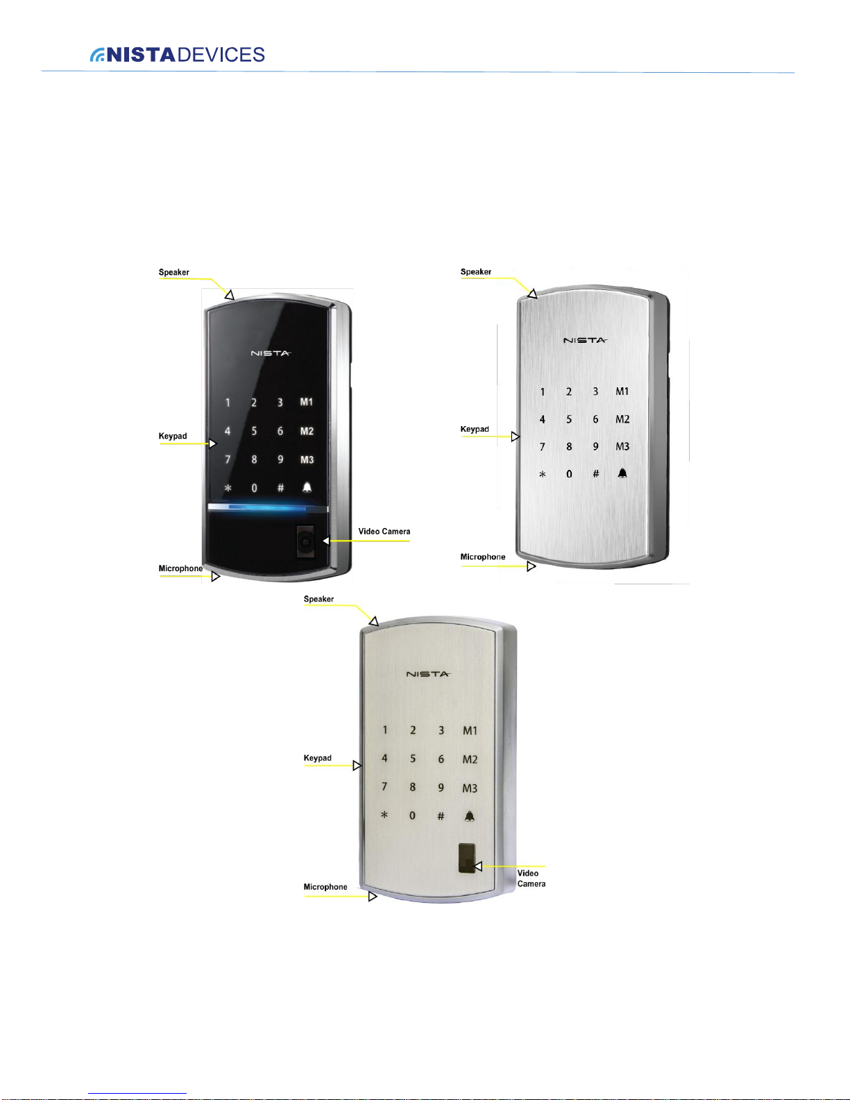
The Door Phone front panel contains a built-in speaker, a microphone, Piezo or Touch-keypad and internal video
camera window (optional)
Figure 4-1 The Analog Door Phone Front Panel (Touch and Piezo Keypads editions)
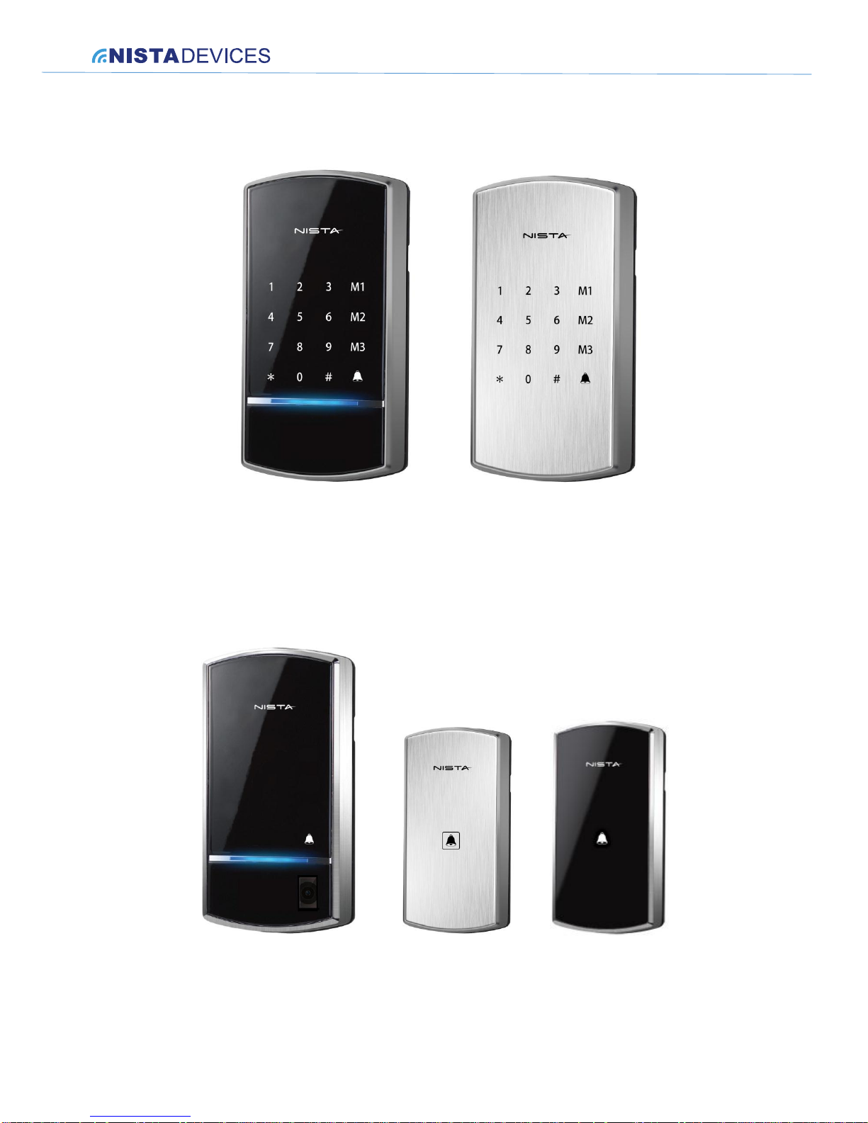
The Analog Door Phone can be supplied in KEYPAD or SINGLE BUTTON editions.
The Analog Door phone Keypad edition equipped with the Touch or Piezo keypad 4x4: 16 buttons, where 12
buttons are standard telephone keypad: 0~9, * and # and additional row of 4 buttons are special functional buttons:
Page 8
NISTA DEVICES GmbH 2013 © All Rights Reserved
8
M1,M2 and M3: banks of speed dial memories
‘Ring’ button which shown on the keypad as ‘Bell’ icon purposed for the dialing and call cancellation
operations
Figure 4-2 Analog Door phone Keypad edition
The Analog Door phone Single Button edition equipped with the Single button keypad with button marked with the
‘Bell’ icon. This button is purposed for the call initialization and cancellation.
The Analog Door phone Single Button edition available in regular and mini housing. The unit’s physical dimensions
see in Chapter 9.
Figure 4-3 Analog Door Phone Single button edition with regular and mini housing
Page 9
NISTA DEVICES GmbH 2013 © All Rights Reserved
9
5 The Analog Door Phone Schematic setup
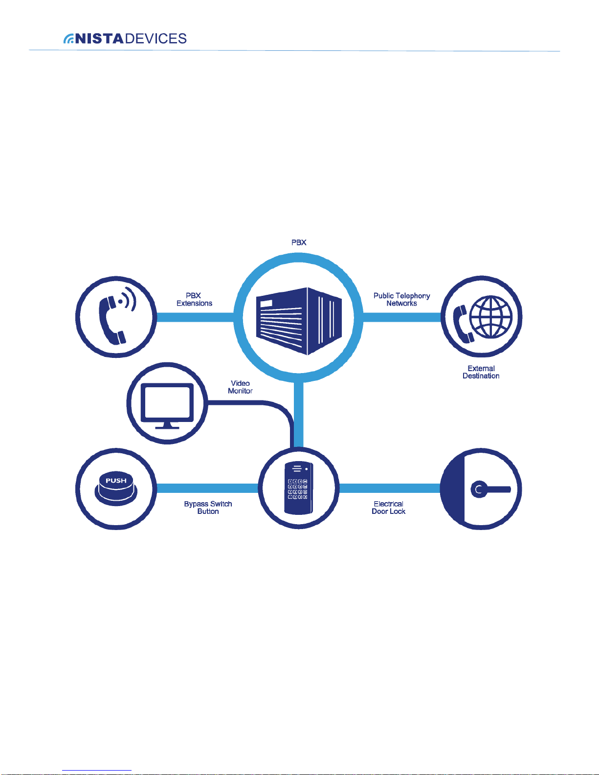
The Door Analog unit can be integrated with the office PBX (PABX) as simple analog extension/telephone
(SLT).
The unit powers the door lock, provided it is powered by an external supply
The unit powers the door lock, provided it is powered by its internal relay’s pins ( See Figure 6-4)
The unit dials to predefined ‘Day’ and ‘Night’ operators via PBX
The unit dials directly to local PBX extensions or external destination numbers via PBX
The unit dials to pre-programmed Speed Dial destination numbers via PBX
The unit opens doors by using the Bypass Switch button
The unit provides analog video stream directly to video monitor
Figure 5-1 details the unit schematic setup.
Figure 5-1 The Analog Door Phone schematic setup
Page 10
NISTA DEVICES GmbH 2013 © All Rights Reserved
10
6 Installation
6.1 Physical installation
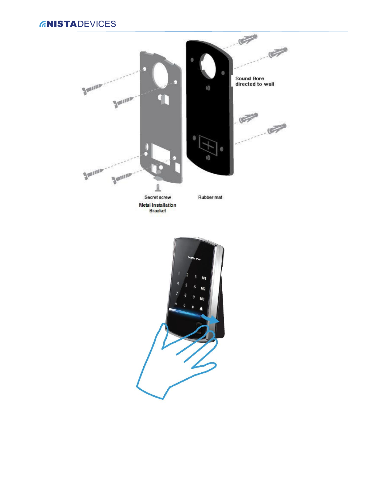
The Door phone can be mounted on the installation bracket provided with the unit.
To install the Door Phone Touch keypad on the wall:
Open the Door Phone case by rotating the secret screw on the bottom of the unit.
Figure 6-1 Door Phone wall installation
To install wall bracket:
1. Measure and mark the location of the holes on the wall, where holes will be drilled.
2. Drill the holes and insert the wall dowels into the holes.
3. Attach rubber mat on the wall and then metal installation wall bracket using the provided wall screws. ( See
Figure 6-1 ). The rubber mat shall be directed to a wall with the rugged side.
4. Connect all required wired connections
5. Put the Door Phone’s front panel into the latch, then close the case and lock the secret screw
Page 11
NISTA DEVICES GmbH 2013 © All Rights Reserved
11
Figure 6-2 Installation bracket
Figure 6-3 Closing the Door Phone house
Page 12
NISTA DEVICES GmbH 2013 © All Rights Reserved
12
6.2 Electrical connections
Note:
The connector PIN’s outputs placement is the same for the regular and mini housing
devices.
The wiring connector is a screw connector type. In order to attach a wire, you must insert the stripped end of the
wire into the appropriate wire connector’s pin and tighten the terminal screw. This will bring together the wire
connection.
To avoid damage to the Door Phone, the external power supply should be
disconnected from mains prior to connecting wires to the Door Phone
unit.
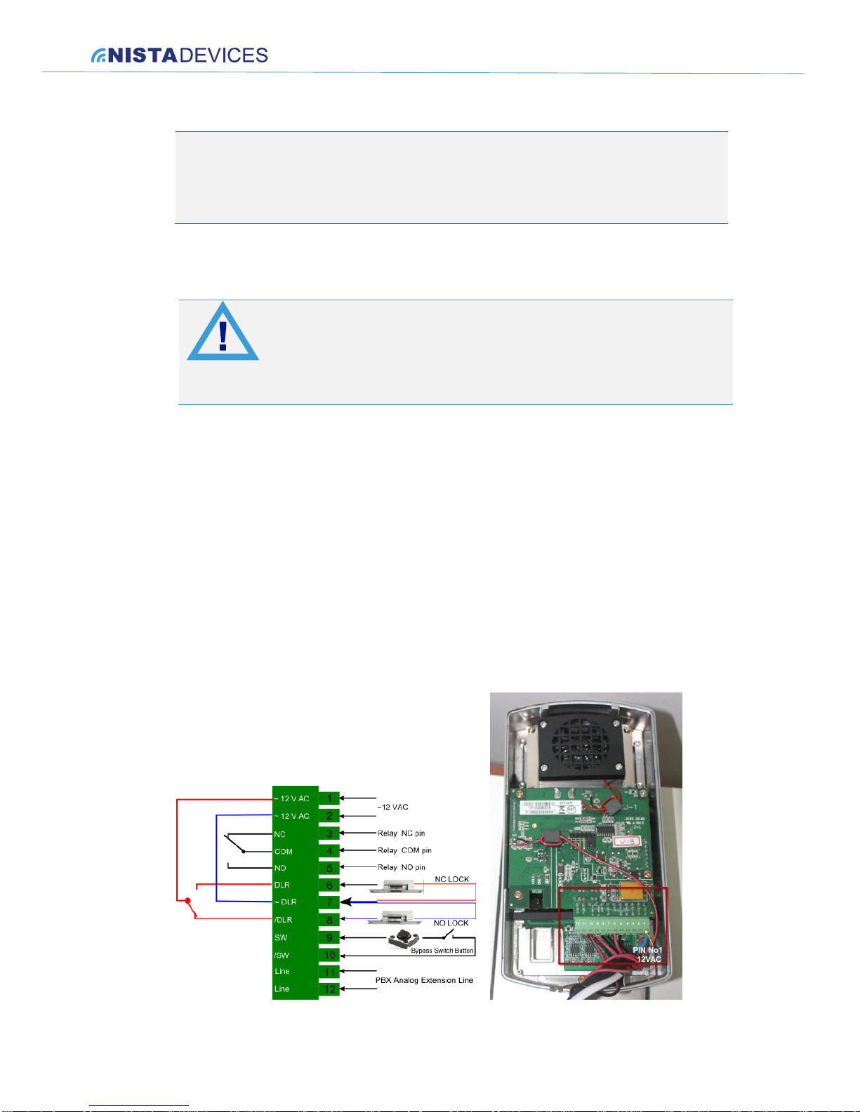
1. Remove the keypad panel cover from the Door Phone unit and find wire connectors at the PCB module. ( See
Figure 6-4 )
2. Connect the two 12V lead wires from the 12V AC power adapter, one to each of the “~12V” pins.
3. Connect the two PBX analog extension wires, one to each of the “LINE” pins.
4. Connect the door-lock relay wires to the “DLR” and “~DLR” terminals if the electrical door-lock relay is a
powered-locked-state type lock, or otherwise connect the door-lock relay wires to the “/DLR” and “~DLR”
terminals.
5. If a bypass switch button is used, connect the button wires to the “SW” and the “/SW” terminals.
6. Plug the wire connectors to the Door Phone PCB module.
7. Attach the Door phone onto the installation bracket.
8. Switch On the external power supply.
Figure 6-4The SD-40X Model Door Phone wires connector
Page 13
NISTA DEVICES GmbH 2013 © All Rights Reserved
13
Note:
1. ~DLR/DLR(/DLR) pins provide voltage to electrical door lock. The maximum supported
electrical current is 2A
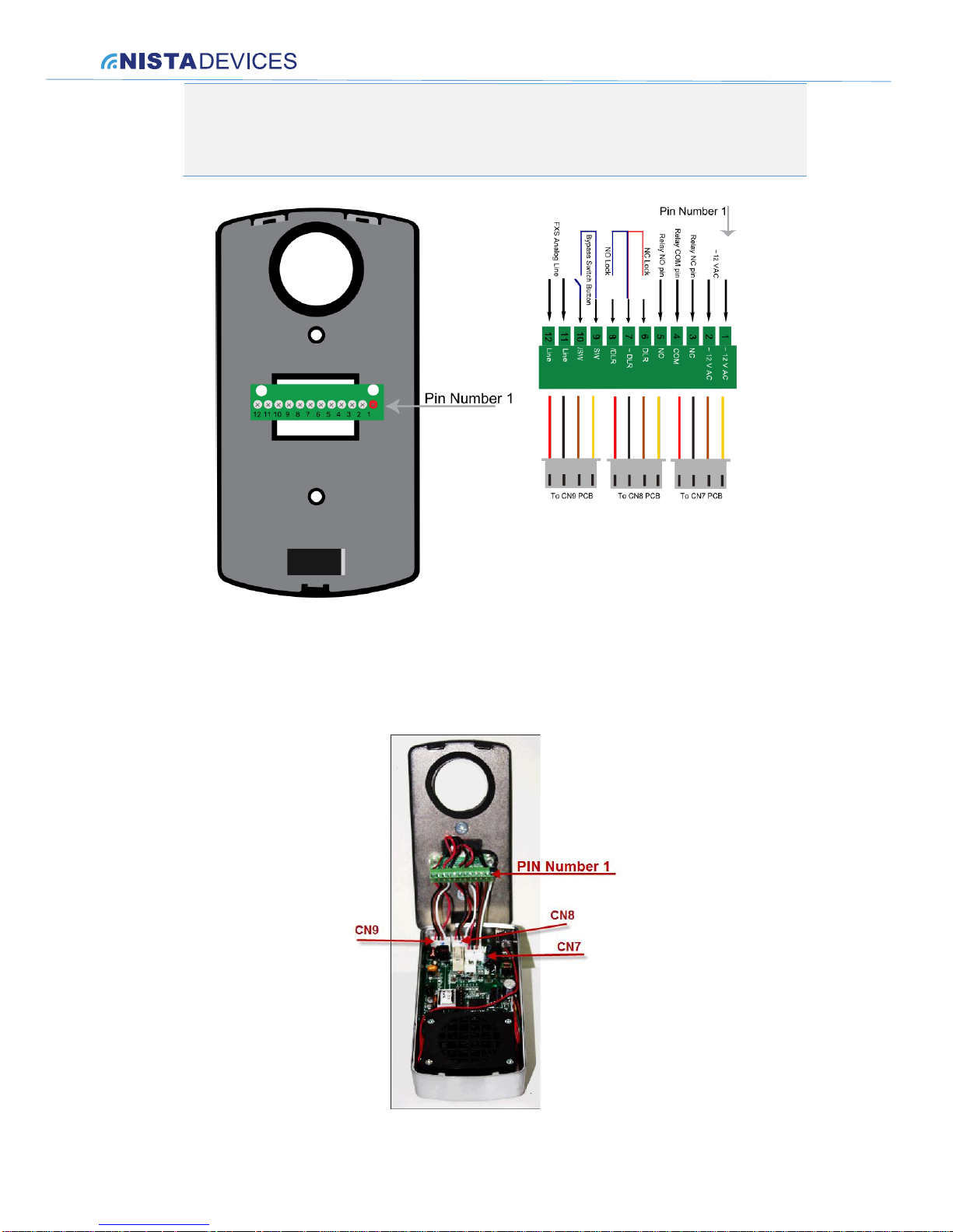
Figure 6-5 SD-30X Model External interfaces connector
SD-30X family devices connector is due-sides connector and includes 2 set of connections:
Connections to peripheral interfaces See Figure 6-5
Connections to SD-30X PCB on-board sockets CN7, CN8 and CN9.
Figure 6-6 SD-30X Connector PCB Connections
Page 14
NISTA DEVICES GmbH 2013 © All Rights Reserved
14
6.3 Video Camera Installation
The SD-40X models can be optionally supplied with integrated internal analog video camera. The SD-30X models
supports the external video cameras only
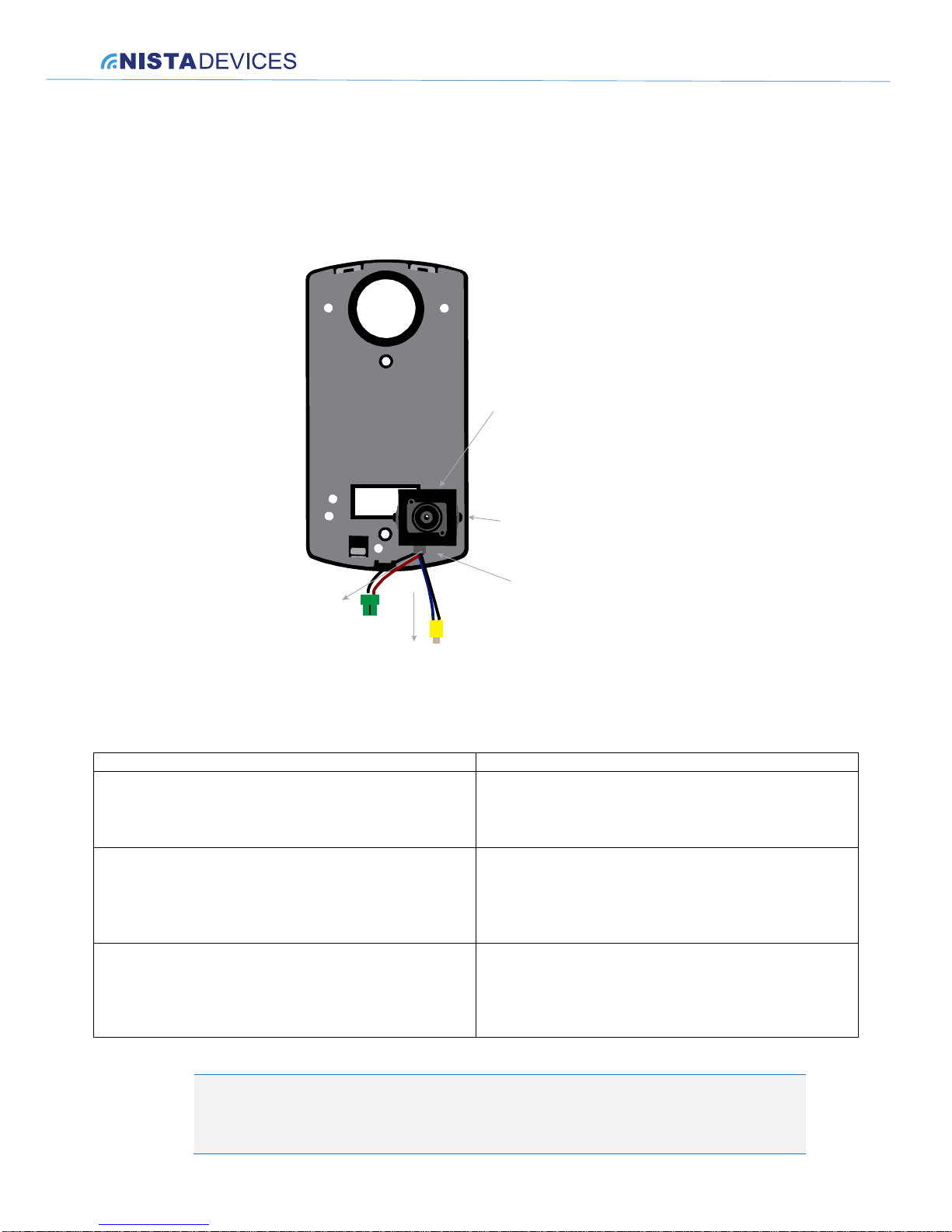
Video camera installs on the SD-40X metal installation bracket ( See Figure 6-1)
The video camera angle of view can be adjusted by manually changing the angle of horizontal position.
The video camera includes 2 wired connections:
Connector
Description
SD-40X 2 wired cable with 2-Pin’s green powering
connector
The Video Camera powering connector. Shall be
connected to appropriate socket on the main PCB. See
Chapter 6.4 Pin-outs colors: Black – GND; Red-12VDC
SD-30X 2 wired cable with 2-Pin’s powering connector
The External Video Camera powering connector. Shall
be connected to appropriate socket on the main PCB.
See Figure 6-8. Pin-outs colors: Black – GND; Red12VDC
BNC or RCA (optionally) analog video connector
The Video Camera analog output connector.
Can be used for connection to analog video monitor.
Pin-outs colors: Black – GND; Blue-Video out
Note:
The Video Camera functionality detailed described in Chapter 7.8
To 12VDC
connector
To analog
video monitor
(BNC or RCA)
Video camera powering
and video output connector
The angle of view
horizontal adjustment
Video Camera
Page 15
NISTA DEVICES GmbH 2013 © All Rights Reserved
15
The SD-30X models supports 12VDC power for external video camera only
6.4 Internal / External Video Camera powering connector
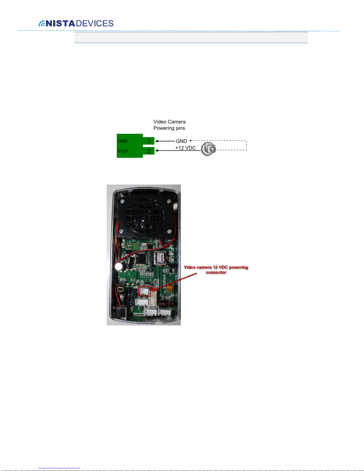
The Door phone provides an option to power internal or external video camera with 12V DC voltage. The power
supplies via 2-pin connector installed on PCB board.
Video camera powered in accordance with configuration rules and use cases ( See DTMF programming code *400
Chapter 8.4)
Figure 6-7 The SD-40X Video Camera powering connector
Figure 6-8 The SD-30X External Video Camera powering connector
Page 16
NISTA DEVICES GmbH 2013 © All Rights Reserved
16
7 User’s Operations
Note:
1. The Single Button door phones provides limited functionality. The limitations depend on the Door
phone’s keypad usage.
2. Pressing the ‘Ring’ button a second time performs the “Call Cancellation” function.
7.1 Access by using the ‘Door Access Code’
For the door opening:
Dial the known ‘Door Access Code’ on the keypad
Door shall be open and accompanied by ‘Confirmation’ tone ( Product signaling tones described in
Chapter 8.1 )
Note:
1. The default door access code is ‘4321’. Read Chapter 8.4 in order to configure the ‘Door Access
Code’
2. Door phone supports up to 9 digits Door Access Code
3. This specific operation is available in Keypad units only
Door will be opened during the ‘Door Opening Time’ interval.
Note:
1. The ‘Door Opening Time’ interval can be configured by using the Door Phone programming codes
( See also Chapter 8.4)
2. The default Door opening time is 3 seconds
7.2 Door opening by using the Bypass Switch button
The Door phone supports a bypass switch installation. This allows the door opening with a hardwired switch
button. A bypass switch button should be connected to the SW and /SW terminals. (See Figure 6-4)
The door will be opened, regardless of the Door Phone telephony connection status.
7.3 Call to the Day / Night Operator
Door phone can operate in ‘Day’ and ‘Night’ modes. The Operator destination number can be configure d for each
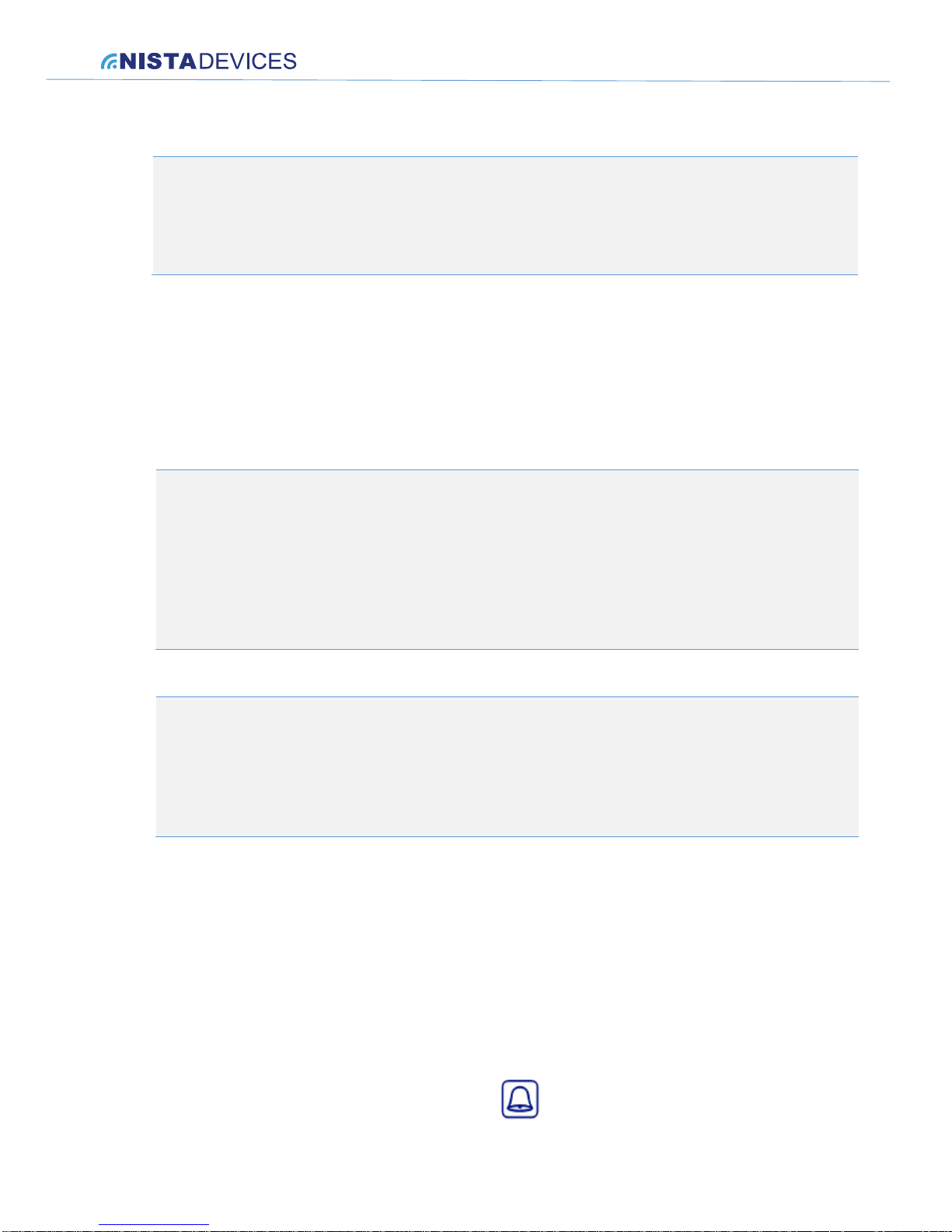
mode separately. The number will be dialed when pressing button.
Page 17
NISTA DEVICES GmbH 2013 © All Rights Reserved
17
To dial Operator:
Press on the button
Door phone dials to a preconfigured Operator number, depending on the Operational mode: Day or Night
Note:
1. Day and Night operational modes can be switched manually by System Operator by using incoming
call to a unit, enter to programming mode and appropriate DTMF code ( See Chapter 8.2 )
2. The default Operator destination numbers are empty and must be configured by using Door Phone
programming codes ( See also Chapter 8.4)
7.4 Direct Call to destination number
To dial directly to destination number:
Dial required destination number by using the keypad buttons
Press button when finished or wait until the ‘Inter Digits Timeout’ interval
Door phone dials destination number
Note:
1. The first prefix digit of dialed number shall be allowed for dialing. See Door Phone programming
codes ( See Chapter 8.4) :
a) ‘Programming 1-prefix-digit(s) for dialing outgoing calls’
b) Inter Digits Timeout
2. The maximum destination number length is 20 digits
3. Operation available for Keypad units only
7.5 Dialing by using Speed Dialing Memories
The Door Phone Keypad edition supports up to 36 Speed Dialing memories, where each memory can store up to 20
digit destination numbers.
Note:
The number of supported Speed Dial Memories depends on the Door Phone configuration. Contact your local
distributor in order to check the unit configuration.
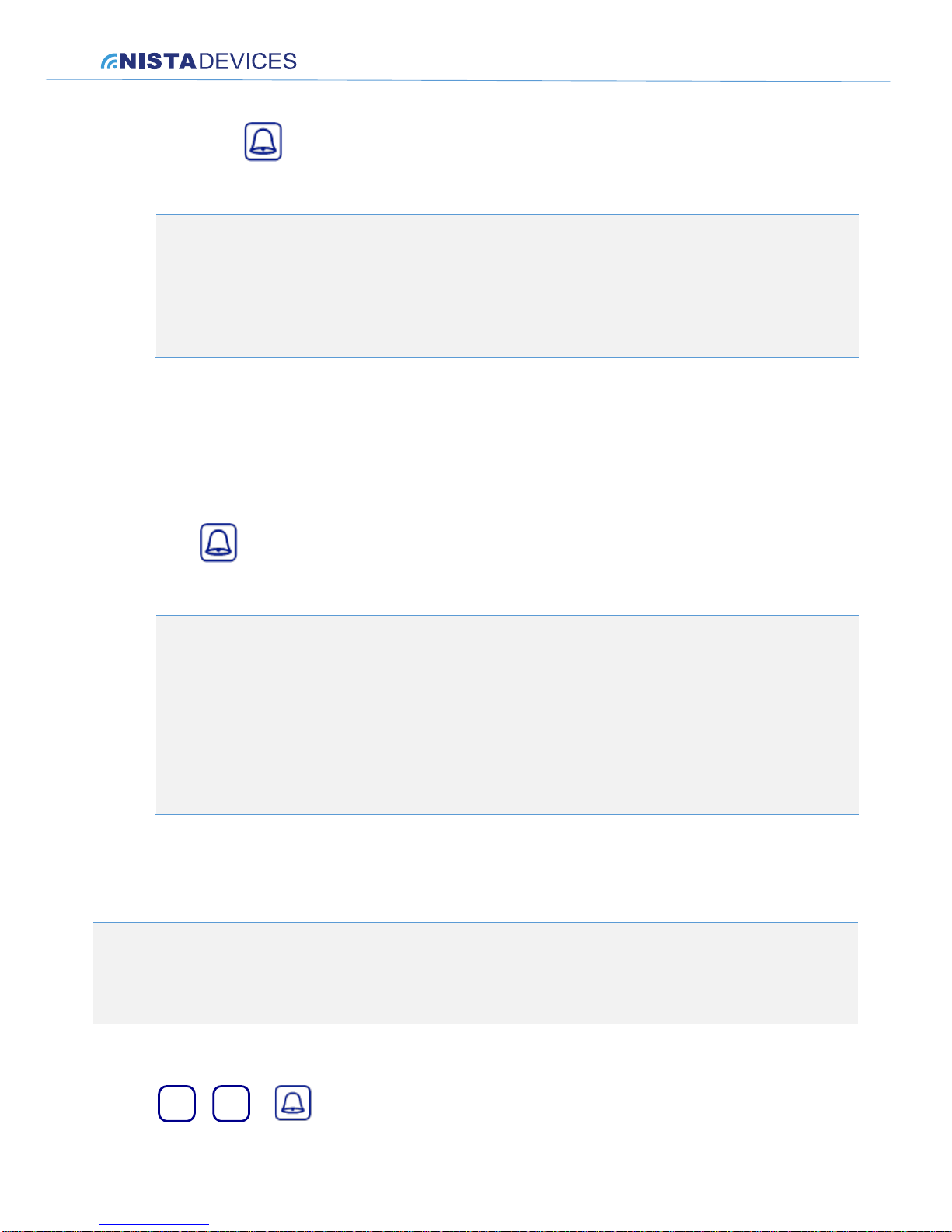
Each Speed dial memory can be specified by using Keypad buttons:
1
~
9
+
Page 18
NISTA DEVICES GmbH 2013 © All Rights Reserved
18
+
M1+M2
M3
+
1
~
9
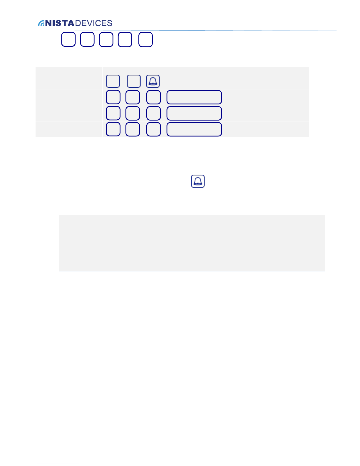
+ Time Delay = ‘INTER-DIGIT DELAY TIME ( See Command *104)’
Next table shows the codes of Speed dialing memories banks
Memory bank
Speed Dialing Codes
From 1 to 9
1
~
9
+
From 11 to 19
+
+
M1
1
~
9
Inter Digit Delay Time
From 21 to 29
+
+
M2
1
~
9
Inter Digit Delay Time
From 31 to 39
+
+
M3
1
~
9
Inter Digit Delay Time
For Speed Dialing:
Dial the required Speed Dialing memory code, where button must be used as End Of Dialing sign for
Memory Banks 1~9 and can be optionally used for Memory Banks M1,M2 and M3
Door phone dials to pre-configured destination number
Note:
1. The Speed Dialing memory maximum destination number length is 20 digits
2. The Speed dialing memory destination number can be configured by using the Door Phone
programming codes (See Chapter 8.4)
3. Operation is available for the Door Phone Keypad edition only
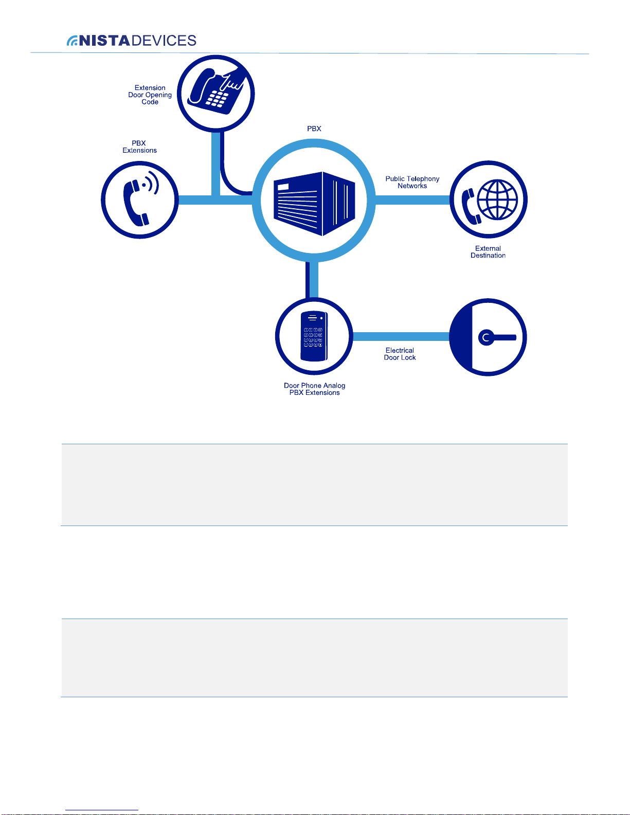
7.6 Door opening from PBX Extension by using the
Extension’s Door Opening Code
Called Destination can open the door for guests remotely by dialing the ‘Extension’s Door Opening Code’ in
conversation mode.
To open a door from Extension:
Call to destination as described in Chapters: 7.2, 7.4, 7.5
Wait till destination answers
Destination extension can dial the ‘Extension Door Opening code’ during conversation in order to open a
door
The call will be disconnected after door opening procedure
Page 19
NISTA DEVICES GmbH 2013 © All Rights Reserved
19
Figure 7-1 Door opening from remote Extension during conversation
Note:
1. The default Extension’s Door opening code is ‘5’
2. The call will be disconnected automatically after door opening from extension
3. The ‘Extension Door opening code’ can be configured by using the Door phone programming codes
7.7 The maximum conversation time
The Door phone controls the conversation time duration. When preconfigured conversation time expired Door phone
disconnects a call.
Note:
1. The default Maximum conversation duration time is 60 seconds
2. The Maximum conversation time interval can be configured by Door Phone programming codes in interval from
10 seconds to 99 seconds or with Unlimited value
Page 20
NISTA DEVICES GmbH 2013 © All Rights Reserved
20
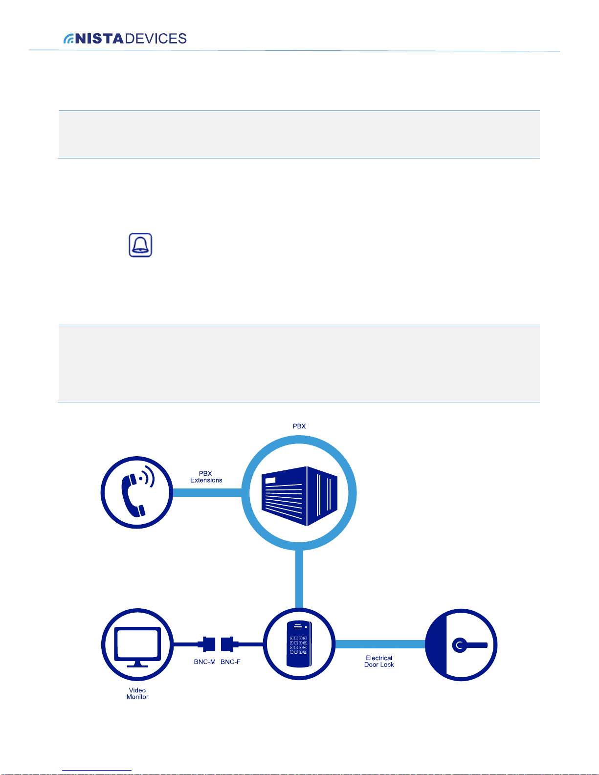
7.8 Video Monitoring
Door phone can optionally be completed with the internal video camera.
Note:
The Door Phone Touch Single Button Mini housing edition provides an option to connect external video camera
only.
Door phone provides the analog video stream, which can be direct to video monitor. Video stream can be provided in
following optional modes:
Always Off
Always On
When button is pressed
When any keypad key is pressed ( For Keypad edition only)
When the telephone line is hang off , but disable in a programming mode ( *911 )
When the telephone line is hang off
The video functional mode can be configured by using the Door Phone Programming codes (See Chapter 8.4).
Note:
1. Door Phone with installed internal video camera includes the video BNC coaxial Output connector for physical
connection with the external video monitor
2. The recommended video cable maximum length is 20 meters
Figure 7-2 Video Monitoring Connections
Page 21
NISTA DEVICES GmbH 2013 © All Rights Reserved
21
8 Programming
8.1 Enter to programming mode
Programming can be released from any PBX extension telephone by calling to Door phone PBX extension number
and using telephony keypad during conversation.
Note:
Door phone can be programmed by using DTMF tones during telephony conversation and programming
session.
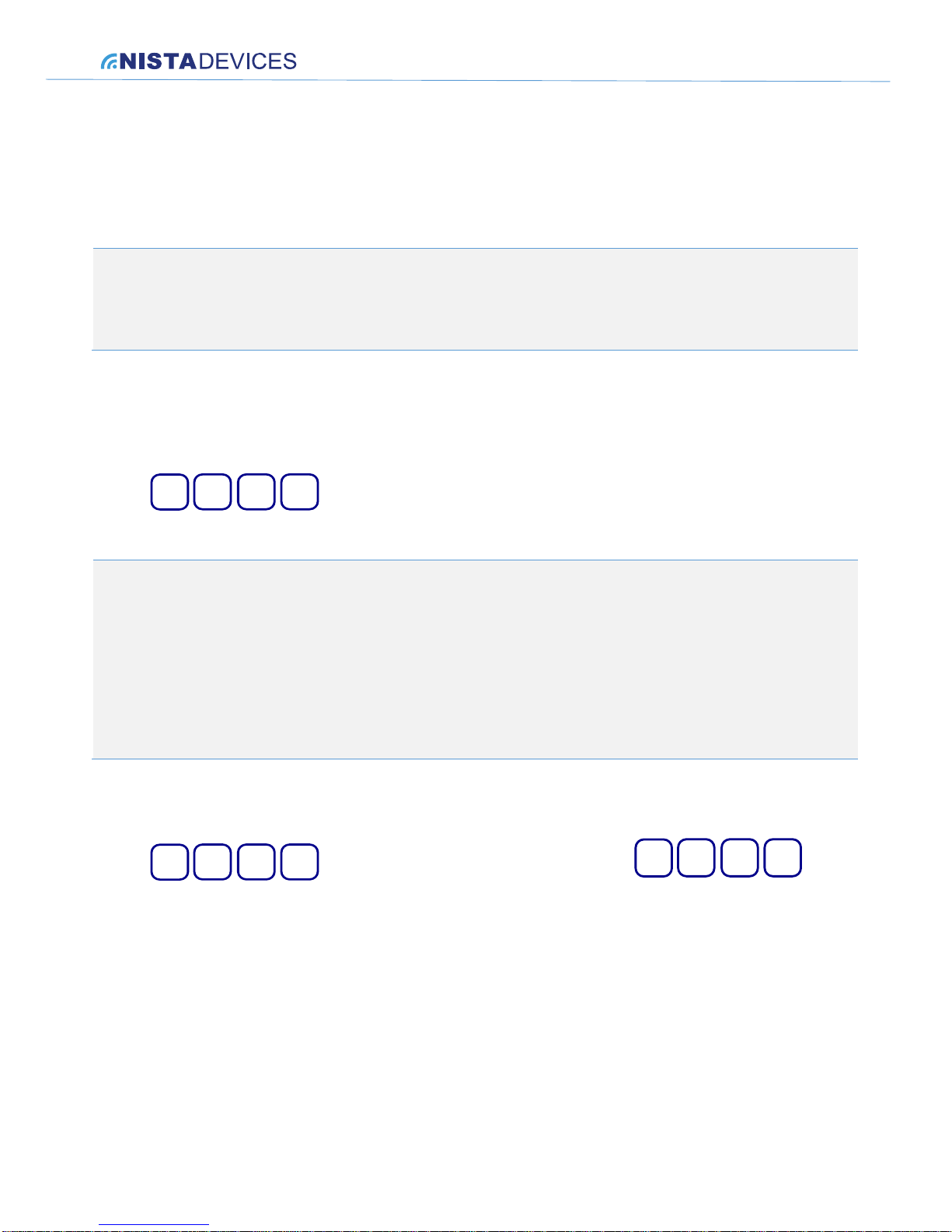
Entering Programming Mode
1. Dial the Door Phone’s extension number from any touch-tone telephone.
2. Wait until the Door Phone answers and generates audio tone.
3. Dial
9 1 1
*
and wait for confirmation tone.
4. Enter the Administrator’s Programming Access Password.
Note:
1. The default Administrator’s password is 12345
2. Upon typing incorrect password three consecutive times, Door phone disconnects
3. Will hear a double beep high tone confirmation tone every time when entering a correct programming
parameter and command, or a low one-beep tone when entering an incorrect programming parameter /
command.
4. The accompanied tone playback marked as ‘(tone)’ in DTMF configuration codes table
To exit the programming mode
1. Dial
9 1 1
*
or programming login time limited by command
9 0 3
*
.
Page 22
NISTA DEVICES GmbH 2013 © All Rights Reserved
22
8.2 To change the Day/Night operational mode:
1. Dial the Door Phone’s extension number from any touch-tone telephone.
2. Wait until the Door Phone answers and generates audio tone.
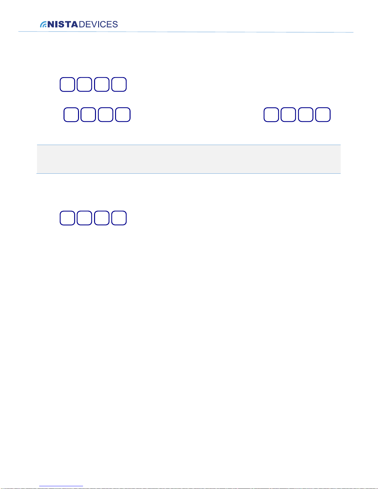
3. Dial
9 1 1
*
and wait for confirmation tone.
4. Enter the Operator’s Programming Access Password.
5. Enter
9 0 1
*
to switch a Door Phone to the Day mode or Enter
9 0 2
*
to
switch a Door Phone to the Night mode
Note:
The default Operator’s password is 54321
8.3 To reset the unit to factory default:
1. Enter programming mode
2. Dial
9 2 0
*
3. A call disconnected and product restarts in it’s default configuration
Page 23
NISTA DEVICES GmbH 2013 © All Rights Reserved
23
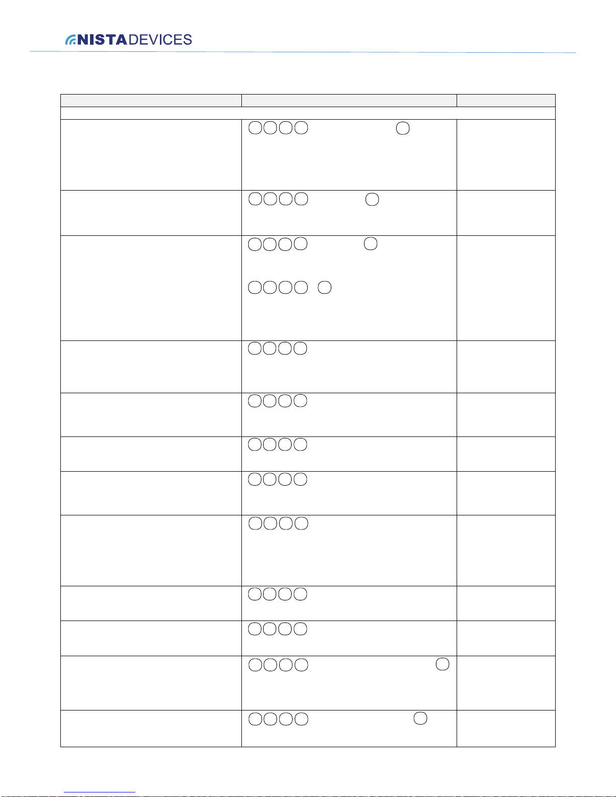
8.4 Door Phone Programming codes
Function
Command Code
Default value
Telephony Operations
The Day/Night Operator destination number (DN)
will be dialed when the ‘Ring’ button is pressed,
respective to Day/Night operational mode.
*
1 0 0
+
DN +
#
X (tone)+
where:
X = 1 Day
X = 2 Night
Destination number (DN) = Up to 20 digits, including *, #,
Pause, and A-D characters.
For special character input, see Chapter 8.5
Day – Empty
Night - Empty
Delete a Day or Night Operator destination number
(DN).
*
1 0 0
+
#
+
X (tone)
where:
X = 1 Day
X = 2 Night
Programming 1-digit(s) prefix to allow dialing
outgoing calls. When beginning with these digits,
the door phone will process dialing.
*
1 0
1
+
Prefixes
+
#
Prefix: digits 0~9 only
To cancel this operation, enter:
*
1 0 1+#
Example: Command *101 259 #(tone) allows dialing
to destination numbers with first digit 2,5 and 9
Note: Parameter doesn’t take effect on Speed Dial
memories destination numbers dialing.
The Maximum Conversation time (sec)
*
1 0 2
XX
+
where:
XX = Seconds (10-99)
00 = Unlimited
60 seconds
Time interval between DTMF digits during
outgoing dialing
3
*
1 0
+ X
where:
X = 1-9
(Each step is 200 msec)
=2 (400 msec)
Inter Digits dialing time out (in sec)
*
1 0
+ X
4
where:
X = Seconds 1~9
3 sec
Number of busy tone cycles in order to detect the
busy signal
*
1 0
+ X
5
where:
X= 0 ~ 9
(0 – no busy detection, 1 – 2 cycles, 2 – 4 cycles, etc.)
3 ( 6 cycles)
Busy signal Cadence configuration for Busy
detection
*
1 0 6
+
Y(tone)+NNNN
X (tone)
+
where:
X = 1 – Busy cadence 1
X= 2 – Busy cadence 2
Y = 1 – On, Y=2 – Off
NNNN – time in msec
1 – 500 On, 500-Off
2- 250 On, 250 Off
Pause time after pick up a line and before dialing
*
1 0
+ X
7
where:
X – time in sec 1-9
1
The minimum time in seconds to detect continuous
tone
*
1 0
+ X
9
where:
X –time in seconds 1-9
3
Assigning a Speed-Dial Memory destination
number.
*
1 1
+M(tone)
0
#
X (tone)
+
+
DN
+
M-Memory bank: 0,1,2 or 3
X = a digit 1 through 9,
DN = Destination number = Up to 20 digits, including *, #,
Pause, and A-D characters.
Empty
Canceling a Speed-Dial destination
*
1 1
+M(tone)
0
#
X (tone)
+
+
M-Memory bank: 0,1,2 or 3
X = a digit 1 through 9
Page 24
NISTA DEVICES GmbH 2013 © All Rights Reserved
24
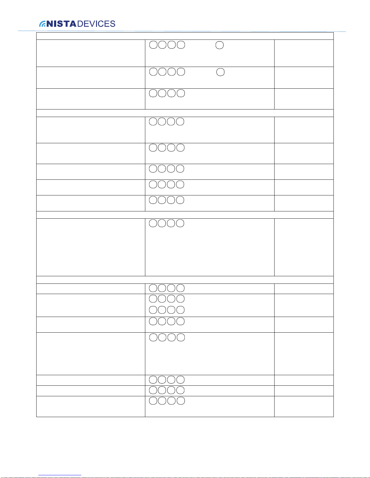
Door Opening Codes
Changing the Opening door Access Code
*
2 0
+ CODE
0
+
#
Door Access Code ‘CODE’ can be up to 9 numeric digits. Do
not use the * or # keys.
4321
Digit(s) code to open the door from dialed
destination number during conversation
*
2 0+1
+
#
CODE
where:
CODE= Digits (0~9) Up to 4 digits.
5
Door opening time in seconds
*
2 0 3
+ X
where:
X = Number of seconds (1~9)
3 sec
Telephony Line Configuration
Loop disconnect detection
*
3 0 0
+ X
where:
X = 0 off
X = 1 on
1-On
Loop disconnect detection time (msec)
*
3 0 1
+XXXX
Where X – time in msec
1200 msec
Speaker volume adjustment
*
3 0 2
+ X
Where X = 1-8
6
Microphone volume adjustment
*
3 0 3
+ X
Where X = 1-9
6
Continuous tone detection time
*
3 0 5
+ X
Where X – time in sec
3
Video Camera Functionality Configuration
Video Camera functionality configuration codes
*
4 0 0
+ X
where
X = 0 camera off
X = 1 camera on
X = 2 camera powered when ‘Ring’ button is pressed
X = 3 camera powered when any key is pressed
X = 4 camera powered when the telephone line is hang off ,
but disable in a programming mode ( *911 )
X = 5 camera powered when the telephone line is hang off
0-Off
Administration
Enter to programming mode
*
9 1 1
Switch Door Phone to the Day/Night operational
mode
Note: Allowed for System Operator as well
*
9 0 1
- Day Mode
*
9 0 2
- Night mode
Day
Programming login time
*
9 0 3
+ XXX
Where XXX time in seconds 000-999
300 – 5 minutes
Enable / disable M1/M2/M3 memories banks
*
9 0 4
+ X + Y
Where
X=1 , Speed dialing Memories M1 group
X=2 , Speed dialing Memories M2 group
X=3 , Speed dialing Memories M3 group
Y=1-Enable, Y=0 Disable
Disabled
Reset device to its factory default
*
9 2 0
System operator’s up to 9 digits password settings
*
9 3 0
+PASSWORD
54321
Changing the Administrator programming
password
*
9 4 0
+PASSWORD
Programming access password must be up to nine numeric
digits 0~9. Do not use the * or # keys.
12345
Page 25
NISTA DEVICES GmbH 2013 © All Rights Reserved
25
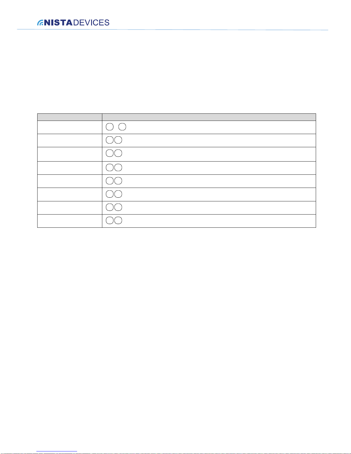
8.5 Special DTMF Characters
Special character/s in destination numbers can be entered using the telephone keypad during programming
procedure. The following table shows the corresponding keypad entries needed for creating special DTMF
characters.
DTMF CHAR.
NUMBER TO DIAL
Digits 0-9
0 9
~
*
* *
Pause
*
1
, configure a 1 second pause
#
*
4
A
*
5
B
*
6
C
*
7
D
*
8
Page 26
NISTA DEVICES GmbH 2013 © All Rights Reserved
26
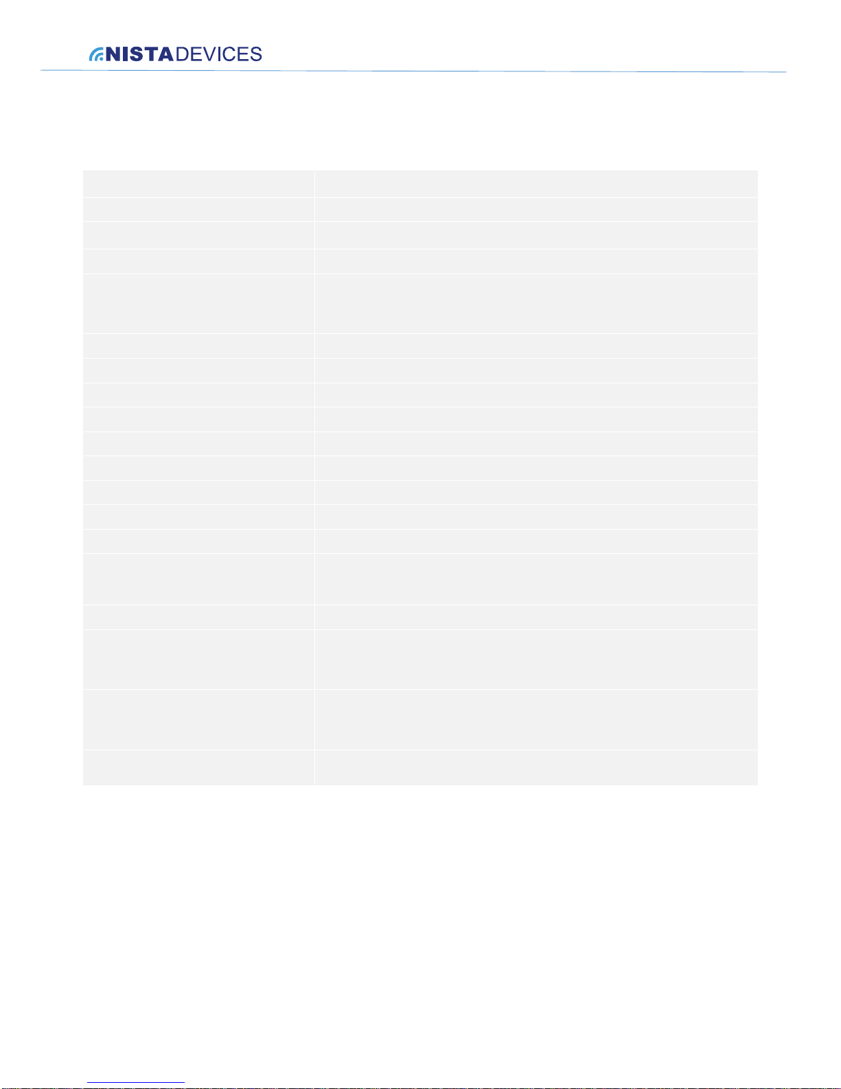
9 Technical specification
Power Supply (External)
12V AC@ 1.6 A (supplied with unit)
Relay Switching Current
2A max
Supported Line Voltage
24-72V DC
DC Leakage
< 10 μA
On-Hook Insulation (Resistance Between
Line Terminal and Ground)
0-100V DC > 5MΩ
100-200 V DC > 30 KΩ
500V AC/50Hz > 20KΩ
100V AC/25Hz > 100KΩ
Ring Capacitor
0.1 μF ±10%
On-Hook Impedance
50V DC, 40V AC/25Hz>3000Ω
Ring Detect
27-100 V AC/16-60 Hz
Ringing Detection time
80 msec
DC Resistance (Off-Hook)
24-66V DC @ 20-100mA/350Ω
Impedance (Off-Hook)
300-3400Hz 500-700Ω
Imbalance Ratio
300-3400Hz > 46dB
Return Loss
300-3400Hz > 18dB
Current During Break
< 700 μA
DTMF Transmission:
Frequency Tolerance
Frequency Level (High)
Frequency Level (Low)
±1.5%
-6 to –8dBm
-8 to –10dBm
Inter-Digit Pause Time
70-80ms
Dimensions
Indoor Unit: ………………182 L x 94 W x 36 H (mm) (with rubber pad)
Indoor Unit Mini Housing: 130 L x 65.5 W x 33 H (mm) (with rubber pad)
Outdoor Unit: …………….182 L x 94 W x 36 H (mm)
Weight
Indoor Unit : ............. ……550g (net)
Indoor Unit Mini Housing: 282.4g (net)
Outdoor Unit:……………..700g (net)
Operating Temperature
Outdoor: -20ºC to +50ºC/4ºF to 122ºF
Indoor: 0ºC to +35ºC/32ºF to 95ºF
Page 27
NISTA DEVICES GmbH 2013 © All Rights Reserved
27
10 Appendixes
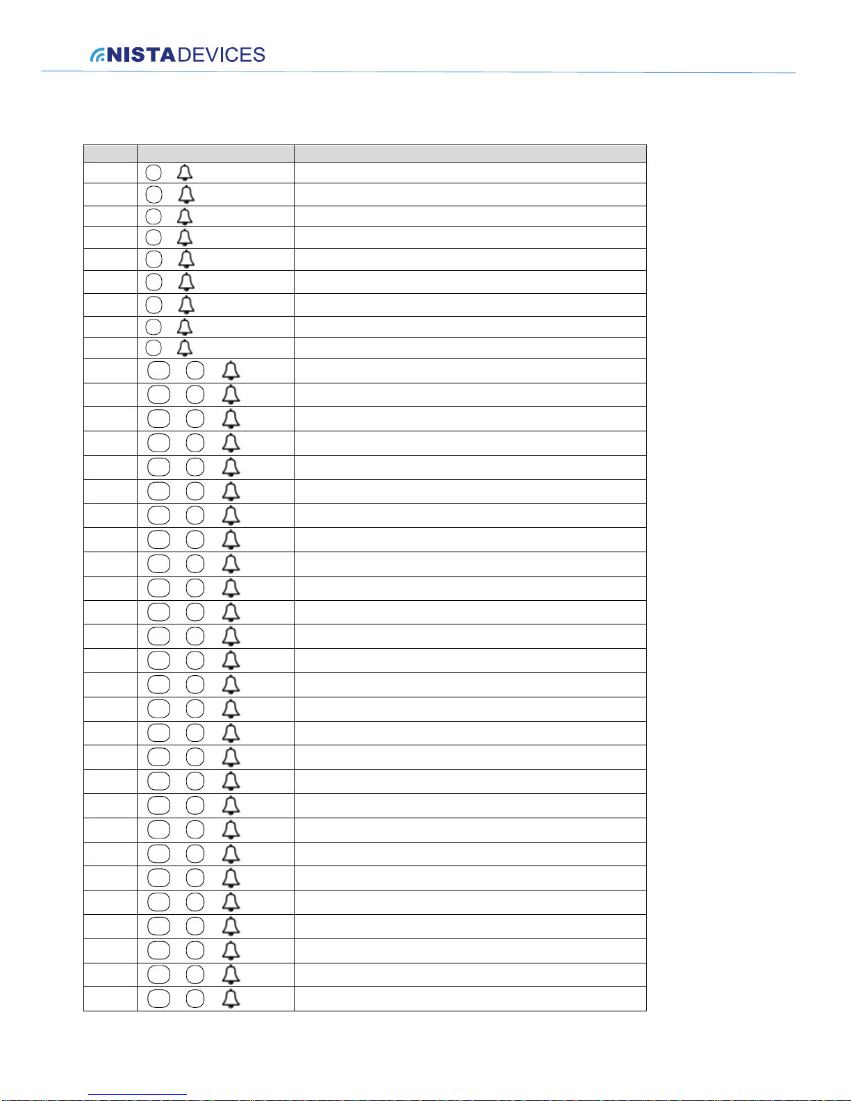
10.1 The Speed dialing memories table
No.
Memory Code
Destination number
1
1
+
2
2
+
3
3
+
4
4
+
5
5
+
6
6
+
7
7
+
8
8
+
9
9
+
10
1
+
M1
+
11
2
+
M1
+
12
3
+
M1
+
13
4
+
M1
+
14
5
+
M1
+
15
6
+
M1
+
16
7
+
M1
+
17
8
+
M1
+
18
9
+
M1
+
19
1
+
M2
+
20
2
+
M2
+
21
3
+
M2
+
22
4
+
M2
+
23
5
+
M2
+
24
6
+
M2
+
25
7
+
M2
+
26
8
+
M2
+
27
9
+
M2
+
28
1
+
M3
+
29
2
+
M3
+
30
3
+
M3
+
31
4
+
M3
+
32
5
+
M3
+
33
6
+
M3
+
34
7
+
M3
+
35
8
+
M3
+
36
9
+
M3
+
Page 28

NISTA DEVICES GmbH 2013 © All Rights Reserved
28
 Loading...