

Nissin WR02 User Manual

株式会社日新テクニカ
ホームページ:http://www.nissin-tech.com
メール:info@nission-tech.com
1
WR02 シリアル(RS232)
WiFi ルーター
変換器
株式会社日新テクニカ
http://www.nissin-tech.com
info@nissin-tech.com
2014/8/2
copyright@2014

株式会社日新テクニカ
ホームページ:http://www.nissin-tech.com
メール:info@nission-tech.com
2
修正履歴
修正日 修正内容
2014/8/2
初作成

株式会社日新テクニカ
ホームページ:http://www.nissin-tech.com
メール:info@nission-tech.com
3
1 Brief Introduction............................................................................................................. 5
2 Summarize......................................................................................................................... 7
2.1 Technical Specifications ................................................................................................7
2.2 Product Outline............................................................................................................8
2.3 External Interface.........................................................................................................8
2.3.1 RS232 ....................................................................................................................9
2.3.2 LAN Interface and WAN interface..........................................................................9
2.3.3 RST Button..........................................................................................................10
2.3.4 5V Power Input....................................................................................................10
2.3.5 Antenna T erminal................................................................................................. 10
2.3.6 LED Indicator light.............................................................................................. 11
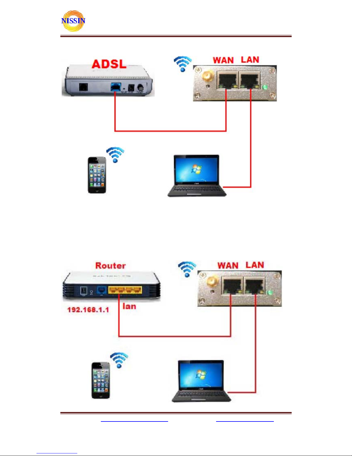
3 Networking mode Brief Introduction ................................................................................ 11
3.1 Star like Network Structure ........................................................................................ 11
3.3 Bus Network structure................................................................................................ 12
3.4 Peer-to-peer Network structure...................................................................................13
4 Quick start Guide............................................................................................................. 14
4.1 Preparatory work.......................................................................................................14
4.2 Power-up Test.............................................................................................................14
4.3 Function Test..............................................................................................................15
5 Product parameter configuration and instruction.............................................................. 16
5.1 Serial Server Logo in.................................................................................................. 16
5.2 Serial server Parameter inquiry..................................................................................16
5.3 WEB network configuration....................................................................................... 17
5.3.1 Serial to Ethernet-dynamic ip...............................................................................18
5.3.2 Serial to Ethernet-static ip....................................................................................18
5.3.3 Serial to WIFI CLIENT-dynamic ip......................................................................18
5.3.4 Serial to WIFI CLIENT-static ip...........................................................................19
5.3.5 Serial to WIFI AP.................................................................................................19
5.4 WEB serial configuration............................................................................................19
5.5 Submitting Alteration................................................................................................. 20
6 Function Description ........................................................................................................21
6.1 Serial to Ethernet .......................................................................................................21
6.2 Serial to WIFI CLIENT.............................................................................................. 21
6.3 Serial to WIFI AP....................................................................................................... 22
6.4 Default mode.............................................................................................................. 22

株式会社日新テクニカ
ホームページ:http://www.nissin-tech.com
メール:info@nission-tech.com
4
6.4.1 TCP Server ..........................................................................................................23
6.4.2 TCP Client........................................................................................................... 23
6.4.3 UDP Server ..........................................................................................................24
6.4.4 UDP Client...........................................................................................................24
7 T ypical application example.............................................................................................. 25
7.1 Active Serial devices connected to the Internet ............................................................25
7.1.1 Application scenarios............................................................................................25
7.1.2 Reference setting (Using Access Control Attendance Machine as an example)........25
7.1.3 Reference Setting figure........................................................................................26
7.2 Passive serial devices connected to the Internet ...........................................................26
7.2.1 Application scenarios............................................................................................26
7.2.2 Reference setting (Take sensor as an example).......................................................27
7.3 Equivalent serial devices connected to the Internet......................................................28
7.3.1 Application scenarios............................................................................................28
7.3.2 Reference setting.................................................................................................. 28
8 Setting for Peer-to-peer (P2P).......................................................................................... 30
8.1 Get UUID................................................................................................................... 30
8.2 Send/Receive data.......................................................................................................30
8.2.1 P2P to open the website of the serial server ...........................................................30
8.2.2 Transfer data by P2P............................................................................................31
※ 使用されたソースコードはhttp://www.nissin-tech.com/
からダウンロードできます。
※ この文書の情報は、事前の通知なく変更されることがあり
ます。
※ (株)日新テクニカの書面による許可のない複製は、いかな
る形態においても厳重に禁じられています。

株式会社日新テクニカ
ホームページ:http://www.nissin-tech.com
メール:info@nission-tech.com
5
1 Brief Introduction
This product is based on the universal serial interface network standard, built-in TCP/IP
protocol stack, enabling the user serial port, Ethernet, wireless network (WiFi) interface between the
conversions.
Through the serial server, the traditional serial devices do not need to change any configuration;
data can be transmitted through the Internet network. Provide a quick solution for the user’s serial
devices to transfer data via Ethernet.
株式会社日新テクニカ
ホームページ:http://www.nissin-tech.com
メール:info@nission-tech.com
6

株式会社日新テクニカ
ホームページ:http://www.nissin-tech.com
メール:info@nission-tech.com
7
2 Summarize
2.1 Technical Specifications
wireless:IEEE 802.11n、IEEE 802.11g、IEEE 802.11b
Network standard
wired:IEEE 802.3、IEEE 802.3u
Wireless transmission rate 11n: maximum up to 150Mbps
11g: maximum up to 54Mbps
11b: maximum up to 11Mbps
Tracks number 1-14
Frequency range 2.4-2.4835GHz
Emission power 12-15dBm
Interface WAN LAN, RS232, DC IN,ANTENNA
Antenna External Antenna 6dB
Functional Parameters
WIFI work mode
Client/AP/
Router(default), default WiFi password: 12345678
WDS Function Support WDS wireless bridge connection
Wireless MAC address filtering
Wireless security function switch
64/128/152 bit WEP encrypt ion
Wireless security
WPA-PSK/WPA2-PSK、WPA/WPA2 security mechanism
Remote Web management
Configuration file import and export
Network management
WEB software upgrade
Serial to Ethernet
Maximum transmission
rate
500000bps
TCP connection Max connection number > 20
UDP connection Max connection number > 20
Serial baud rate 1200~500000bps
Other Parameters
Status indicator Status indicator
Operating temperature:-20~70℃
Operating humidity:10%~90%RH(non condensing)
Storage temperature:-40~80℃
Environmental standard
Storage humidity:5%~90%RH(non cond ensi ng)
株式会社日新テクニカ
ホームページ:http://www.nissin-tech.com
メール:info@nission-tech.com
8
Additional properties
Frequency bandwidth optional:20MHz,40MHz,Automatic
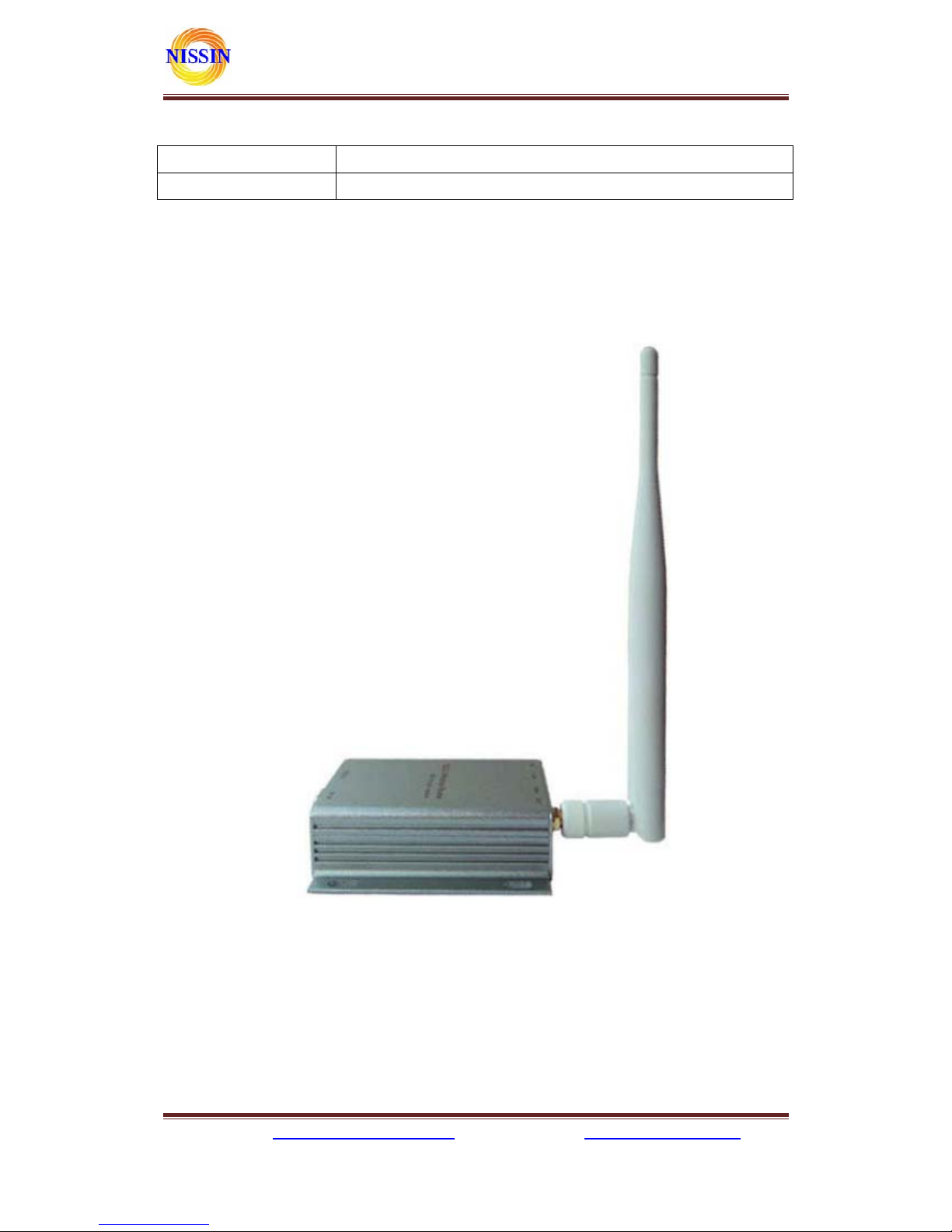
2.2 Product Outline
The outline of the serial WIFI server as follows. Mechanical Dimensions:
85×85×25 mm, not including the antenna.
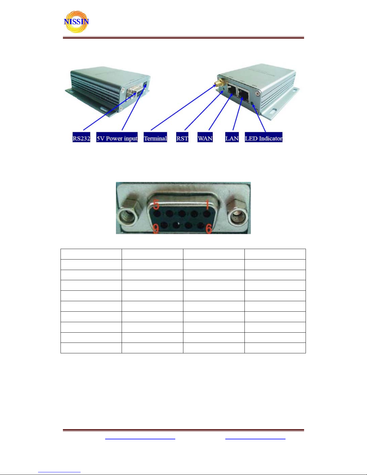
2.3 External Interface
The serial WiFi sever is a serial-WiFi-Ethernet device, its external interface including RS232,
DC IN, LAN, WAN, LED, RST. This section will detail the definition of each interface.
株式会社日新テクニカ
ホームページ:http://www.nissin-tech.com
メール:info@nission-tech.com
9
2.3.1 RS232
The following figure shows a schematic diagram of the external interface of RS232. Interface,
the definition is as follows:
No Function Direction Explanation
1 NC NC None
2 RxD Input Data receiving input
3 TxD Output Data sending output
4 NC NC None
5 GND Input GND
6 NC NC None
7 NC NC None
8 NC NC None
9 NC NC None
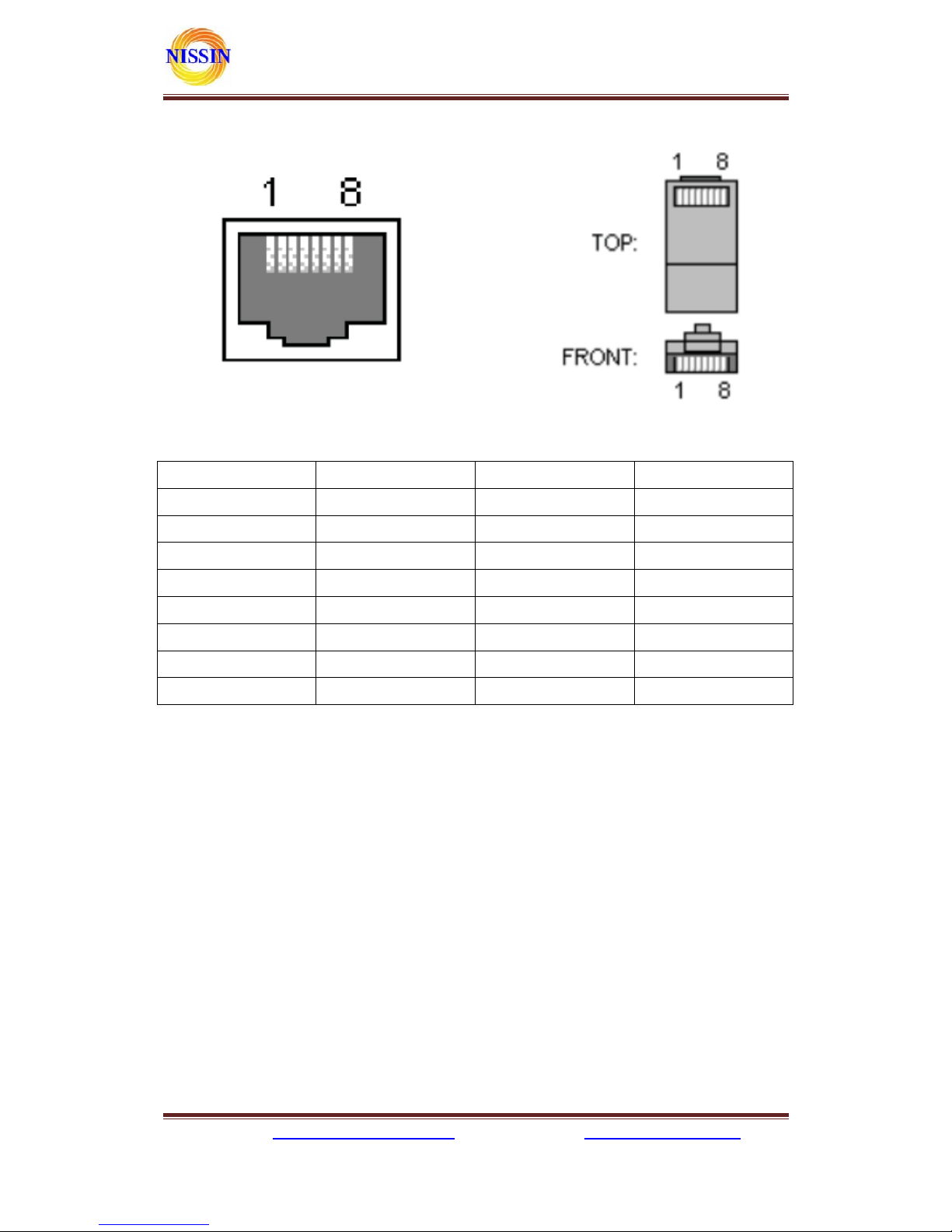
2.3.2 LAN Interface and WAN interface
The serial WiFi server provides two network interface, WAN port and LAN port, the interface is
a standard form of RJ-45 interface. RJ-45 interface definition is shown as below:
株式会社日新テクニカ
ホームページ:http://www.nissin-tech.com
メール:info@nission-tech.com
10
The following table shows the pin definitions of RJ-45:
No Function Direction Explanation
1 TX+ Output Transmit Data+
2 TX- Output Transmit Data3 RX+ Input Receive Data+
4 NC NC
5 NC NC
6 RX- Input Receive Data7 NC NC
8 NC NC
2.3.3 RST Button
RST button is used to reset HLK-WR02 Server to the factory settings. METHODS: When the
device have startup complete, then using sharp object to press the RST button for at least 10 seconds,
all parameters of the server can be set to the default value.
2.3.4 5V Power Input
Voltage range: 4.5 ~ 5.5V. The default configuration of the Device for the power adapter is
5V/1A DC power supply. Power interface: the inner core is positive.
2.3.5 Antenna Terminal
Standard SMA interface within the outer spiral needle, the interface can be equipped with 2.4G
SMA antenna inside the screw hole standard.
 Loading...