

Nissei TM-3000, TM-2000 Instruction Manual

SWR/POWER/MODULATION METE
R
Models : TM-3000/TM-2000 INSTRUCTION MANUAL
INTRODUCTION
TM-3000/2000 is a compact test meter to indicate the condition of 1.6-60 MHz / 26 -30 MHz antenna system
and transmitter with an impedance of 50 ohm. With TM series you can measure SWR, relative output power of the
transmitter and AM modulation.
SPECIFICATIONS
10W/30W/300W/3KW
(AVG) +/- 10% (AVG) +/- 10%
(AVG) +/- 5% (AVG) +/- 5%
POWER, SWR, MOD. POWER, SWR, MOD.
M type (SO-239) M type (SO-239)
190x85x135 (w/o holder) 190x85x135 (w/o holder)
800g (w/o holder) 800g (w/o holder)
Operation Manual Operation Manual
<FRONT PANEL>
<FRONT & REAR PANEL>
1. Meter Display : Indicates FWD/REV power and VSWR ratio, AM
Modulation.
2. Function switch : Selects FWD/REV power, VSWR, and Modulation
3. Range switch : Selects RF power range
4. Calibration control knob : Set full scale deflection when measuring
VSWR and AM modulation
5. AVG/PEP MONI. (elliptical push button) : Selects Average or PEP RF
Power readings
<REAR PANEL>
6. Meter Zero Adj. : Machnical zero adjustment for meter needle
7-
7. TX connector : Coax connector to transmitter 50 Ohm RF output.
8. ANT connector : Coax connector to 50 Ohm antenna system.
9. 13.8V DC connection for meter illumination.
10. Calibration MONI. (round push button) : Selects calibration or SWR
/MOD readings.
9- 8-
Minimum 1W
50 OHM
TM-2000
26 -30 MHz
0W - 1KW
10W/100W/1KW
1KW
MAX 100%
Testing Function
Input/Output Impedance
Input/Output Connectors
Dimension (W/H/D) mm
Weight (Net)
Accessories
3KW
MAX 100%
Minimum 1W
50 OHM
Power Scale
Maximum Power
AM Modulation
Accuracy 10W Range
30W - 3KW Range
SWR Measurement
Model TM-3000
1.6 - 60 MHz
0W - 3KW
Frequency Range
Power Range
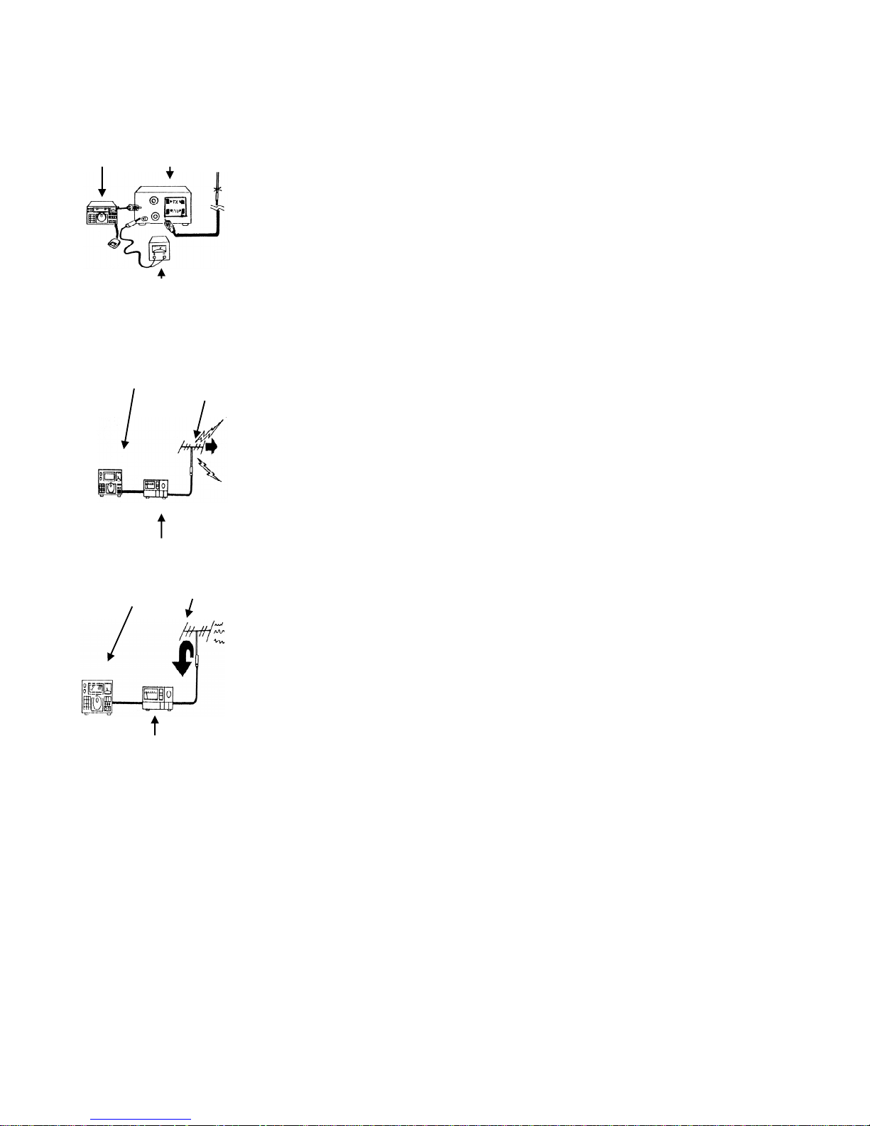
<INSTALLATION>
Transmitter SWR Meter <FORWARD POWER MEASUREMENT>
1. Set the FUNCTION switch to FWD
2. Set the radio transceiver to transmit mode and read the scale corresponding
to the Power Range selected.
3. When the AVG/PEP button is 'out', the meter reads average RF power. When
the button is 'depressed', the meter reads Peak Envelope Power for use with
SSB and AM transmissions.
DC power supply
<REVERSED POWER MEASUREMENT>
This measures the reverse power on the coaxial cable between transceiver and
<OPERATION> antenna. The rest of the settings are the same as that of <FORWARD POWER
Transmitter Forward MEASUREMENT>
<VSWR MEASUREMENT>
1. Set the FUNCTION switch to SWR position
2. Push the Calibration MONI. to CAL/SET position (button "drepressed")
3. Slowly turn the calibration control knob clockwise until the meter pointer is at
full scale position
4. Push the Calibration MONI. to SWR/MOD position (button "out")
SWR Meter Set the transceiver to transmit mode.
Transmitter Reversed
<AM MODULATION LEVEL MEASUREMENT>
1. Set the FUNCTION switch to MOD position
2. Push the Calibration MONI. to CAL/SET position (button "drepressed")
3. Slowly turn the calibration control knob clockwise until the meter
pointer is at full scale position
4. Push the Calibration MONI. to SWR/MOD position (button "out")
Set the transceiver to transmit mode.
SWR Meter
[CAUTION]
1.Since the meter movement is very sensitive, avoid excessive vibration or
mechanical shock to the meter.
2.The meter must never be reverse connected. Always observe the correct
connections to transmitter and antenna as indicated on the rear sockets.
3.The meter has been carefully calibrated at the factory. Tampering with any of
the internal circuitry or sensors may cause damage and will degrade the meter's accuracy.
4.Do not expose the meter to excessive temperatures, high humidity, or strong magnetic fields.
 Loading...