

Page 1
Diirreecctt
D
Usseerr’’ss
U
PR5300 • PR5310 • PR5350 • PR53LE
C
arr
C
a
Nisca Series
d
d
G
G
Prrii
P
uii
u
ntteerr
n
dee
d
TEAMNisca, A Division of Kanematsu USA, Inc. 100 Randolph Road, Somerset, NJ 08873
Copyright © 2005, Kanematsu USA, Inc. All rights reserved.
TEAMNisca® and the TEAMNisca® logo are a registered trademark of Kanematsu USA, Inc. Microsoft® and
Windows® are U.S. trademarks of Microsoft Corporation. Names of products mentioned herein are used for
identification purposes only and may be trademarks and/or trademarks of their respective companies.
Page 2

Page 3

Table of Contents
Chapter 1: Introduction
1.2 Welcome! ............................................................................................................................1
1.3 About This User’s Guide ...................................................................................................1
1.4 General Site Requirements .................................................................................................2
1.5 Important Safety Instructions ..............................................................................................2
1.5.1 Electrical Requirements .............................................................................................3
1.5.2 Physical Requirements ..............................................................................................3
1.5.3 Environmental Requirements ....................................................................................3
Chapter 2: Getting Started
2.1 Printer Features....................................................................................................................4
2.1.1 Front of the Printer ....................................................................................................4
2.1.2 Rear of the Printer ..................................................................................................... 5
2.1.3 LCD Panel .................................................................................................................6
2.1.4 LCD Operation ..........................................................................................................6
2.1.5 Front Access Panel ....................................................................................................7
2.2 Unpacking the Printer .........................................................................................................7
2.3 Loading the Ribbon .............................................................................................................9
2.4 Connecting the Printer ......................................................................................................12
2.4.1 SCSI Connection .....................................................................................................12
2.4.2 Parallel Connection .................................................................................................13
2.4.3 USB Connection .......................................................................................................14
2.5 Loading Cards ...................................................................................................................15
2.6 Card Thickness Adjustment .............................................................................................. 16
2.7 Turning On the Printer ......................................................................................................17
2.8 LCD Modes of Operation .................................................................................................17
2.8.1 Normal Mode Information ......................................................................................17
2.8.2 User Mode Information ...........................................................................................17
2.8.3 Functions of the User Mode ....................................................................................18
Chapter 3: Maintenance
3.1 Basic Automated Cleaning ...............................................................................................20
3.2 Manual Cleaning ...............................................................................................................22
3.3 Cleaning the Takeup Roller ..............................................................................................22
3.4 Cleaning the Input Rollers ................................................................................................22
3.5 Cleaning the Flip/Turn Transport Rollers .........................................................................24
3.6 Cleaning the Print Unit Rollers .........................................................................................24
3.7 Cleaning the Print Head ....................................................................................................25
3.8 Updating the Firmware .....................................................................................................27
Chapter 4: Troubleshooting
4.1 Interpreting LCD Display Messages .................................................................................30
4.2 Interpreting LCD Jam Messages .......................................................................................31
4.3 Card Appearance Issues ....................................................................................................33
4.4 General Troubleshooting Suggestions ..............................................................................34
4.5 Where to Get Additional Help ..........................................................................................35
4.6 PR53xx Series Block Diagram .........................................................................................36
i
Page 4

Appendix A: PR53xx Printer Specifications ............................................................. 37
Appendix B: Printer Configuration ........................................................................... 39
Appendix C: User Mode Menu Map
C-1 PR5300/PR5310 User Mode Menu Map .........................................................................41
C-2 PR5350 User Mode Menu Map........................................................................................43
C-3 PR53LE User Mode Menu Map ......................................................................................45
Appendix D: Parts Replacement
D-1 Replacing the Input Rollers .............................................................................................47
D-2 Replacing the Print Head .................................................................................................48
D-3 Replacing the Fan Filter ...................................................................................................50
ii
Page 5

CHAPTER
1.
Introduction
1.2 Welcome!
Congratulations on your purchase of the Nisca PR53xx Series Direct Card Printer. The printer
gives you brilliant images using these features:
Full color edge to edge
300 dpi dye sublimation printing technology
Industry leading 24-bit continuous tone printing
256 Grayscale printing
High speed printing
Dual sided printing (excluding the PR53LE)
Full Windows®-based application compatibility
This printer produces cards ideal for driver’s licenses, printing bureaus, access control badges,
and standard corporate identification.
1.3 About This User’s Guide
This User’s Guide contains important safety information, along with detailed instructions on how
to install, use and maintain the printer.
This guide uses the following conventions:
Warning
This warning symbol means danger. You are in a situation that could cause
bodily injury. Information presented must be followed carefully to avoid
harm.
Caution This caution symbol means reader be careful. In this situation, the user might do
something that could result in equipment damage.
1
Page 6

Note This note symbol means reader take note. Notes contain important information
and helpful suggestions about your printer.
1.4 General Site Requirements
When choosing a site for the PR53xx series printer, consider the following recommendations:
Select a site that is out of direct sunlight to prevent deformation of the plastic housing and
discoloration of the cards.
Placement should be on a sturdy platform and off the floor.
Platform should be free from vibration.
Environment should be free from high humidity and dust.
Environment should have a relatively stable temperature.
Provide enough space to allow adequate ventilation.
Place it in a location that allows easy access to all sides.
1.5 Important Safety Instructions
Before using your printer, read the following safety instructions to make sure you use the printer
safely and effectively:
Turn off and unplug the printer before cleaning.
Do not spill liquids on the printer.
Always prevent debris from entering the printer.
Do not place heavy objects on the printer.
Use only a power source indicated in the Electrical Requirements section.
Do not place the printer on an unstable surface.
Do not place the printer near a radiator or a heating vent.
Do not place the printer near sources of heat or electromagnetic interference.
Except as specifically indicated and explained in this User’s Guide, do not attempt to
service the printer yourself.
When moving the equipment, always be sure to turn off the power prior to moving.
Do not let the power cord become damaged or frayed.
Do not block the air vents or fan on the printer. Do not touch any part inside the printer
except as directed by this User’s Guide.
Do not use the printer for purposes other than its intended use.
Unplug the printer and refer servicing to qualified service personnel in the event that any
of the conditions exist:
• The power cord or plug is damaged.
• Any liquid or solid object falls into the printer.
• The printer has been dropped or the case has been damaged.
2
Page 7
• The printer does not operate normally or exhibits a distinct change in
performance.
1.5.1 Electrical Requirements
The PR53xx series printer requires the following electrical specifications for optimal
performance:
100-240 VAC at 50/60 Hz. The printer is auto-switching to power within this range.
Single phase, 3-wire grounded receptacle.
If you use an extension cord with the printer, verify it’s rated for a minimum of 125
VAC, 10 Amps.
Warning
Never operate the printer in a location where the operator, computer, or
printer can get wet. Personal injury could result. The printer must be
connected to a grounded electrical power supply and properly protected
against electrical surges and grounding faults.
1.5.2 Physical Requirements
The PR53xx series printer requires a sturdy platform that can accommodate its weight and
physical dimensions. The printer weighs 26.6 pounds (13 kilograms). The dimensions are:
Height: 16.57” (421 mm)
Width: 10.66” (271 mm)
Depth: 10.03” (331 mm)
1.5.3 Environmental Requirements
The PR53xx series printer requires the following environmental conditions for optimal operation:
Operating temperature range of 50° – 95°
temperatures should be in the range of 68° – 77° F (20° – 25° C).
Operating relative humidity range of 35% – 80% non-condensing.
F (10° – 35° C). To ensure best performance,
3
Page 8
CHAPTER
2.
Getting Started
Note This user’s guide explains the operation of the PR5300, PR5310, PR5350 and
PR53LE. Where necessary, the areas that apply only to certain printer models
will be specified.
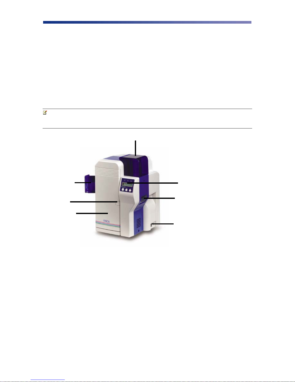
2.1 Printer Features
C
B
A
Figure 2-1: Printer features
2.1.1 Front of the Printer
A. Front Access Panel
D
E
F
G
Opens to allow access to the inside of the printer.
B. Front Access Panel Release Button
Button that allows the front access panel to open.
C. Card Output Stacker
Used to store printed cards.
D. Card Input Feeder
Used to load blank cards for printing.
4
Page 9

E. LCD Panel
Display’s the current status of the printer.
F. Rejected Card Exit
Used to eject a card that encounters a problem.
G. On/Off Switch
Turns the printer power on and off.
2.1.2 Rear of the Printer
A
D
A. Circuit Breaker
Protection device that stops current if there is a direct short or excessive heat.
B. Interface Connection
Available Interface Connection: Refer to Appendix A.
C. Options Connector Port
The printer supports the attachment of an optional card lamination module.
Options connector port not available on PR53LE.
C
B
Figure 2-2: Rear of printer
E
D. Power Receptacle
Supplies power to the printer.
E. RS232C Interface
Interface for RFID encoding and reading modules. Connect using a D-Sub 9 pin
female (DB-9) to a D-Sub 9 pin female. Cable not included. Interface is only
available on models PR5310 and PR5350.
5
Page 10
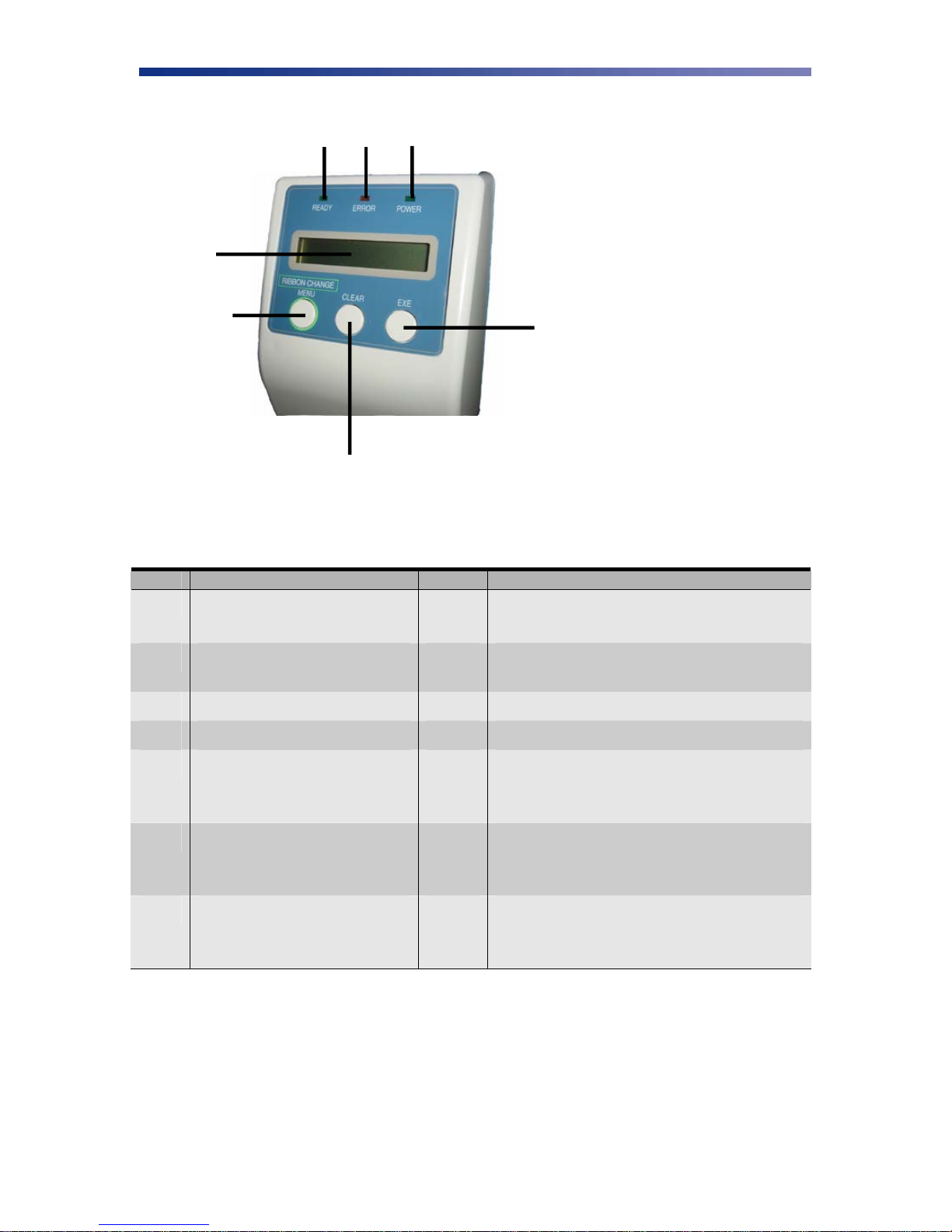
2.1.3 LCD Panel
B
C
D
A
E
G
F
Figure 2-3: Printer LCD panel
2.1.4 LCD Operation
ITEM DESCRIPTION MODE FUNCTION
A LCD Panel Normal
User
Displays the printer’s status.
Displays the selected menu or values.
B Ready LED Green light indicates printer is ready and
will accept data.
C Error LED Indicates an error has occurred.
D Power LED Indicates the power is on.
E Ribbon Change / Menu Button Normal
User
F Clear Button Normal
User
G EXE Button Normal
User
Press this button to change the ribbon. Press
and hold this button enter User’s Mode.
Use this button for menu selections.
Used for clearing or resetting errors. It is
also used to stop continuous printing.
In some cases, it is used to set values.
Not used.
Used to execute the displayed item or to
change the setting.
6
Page 11
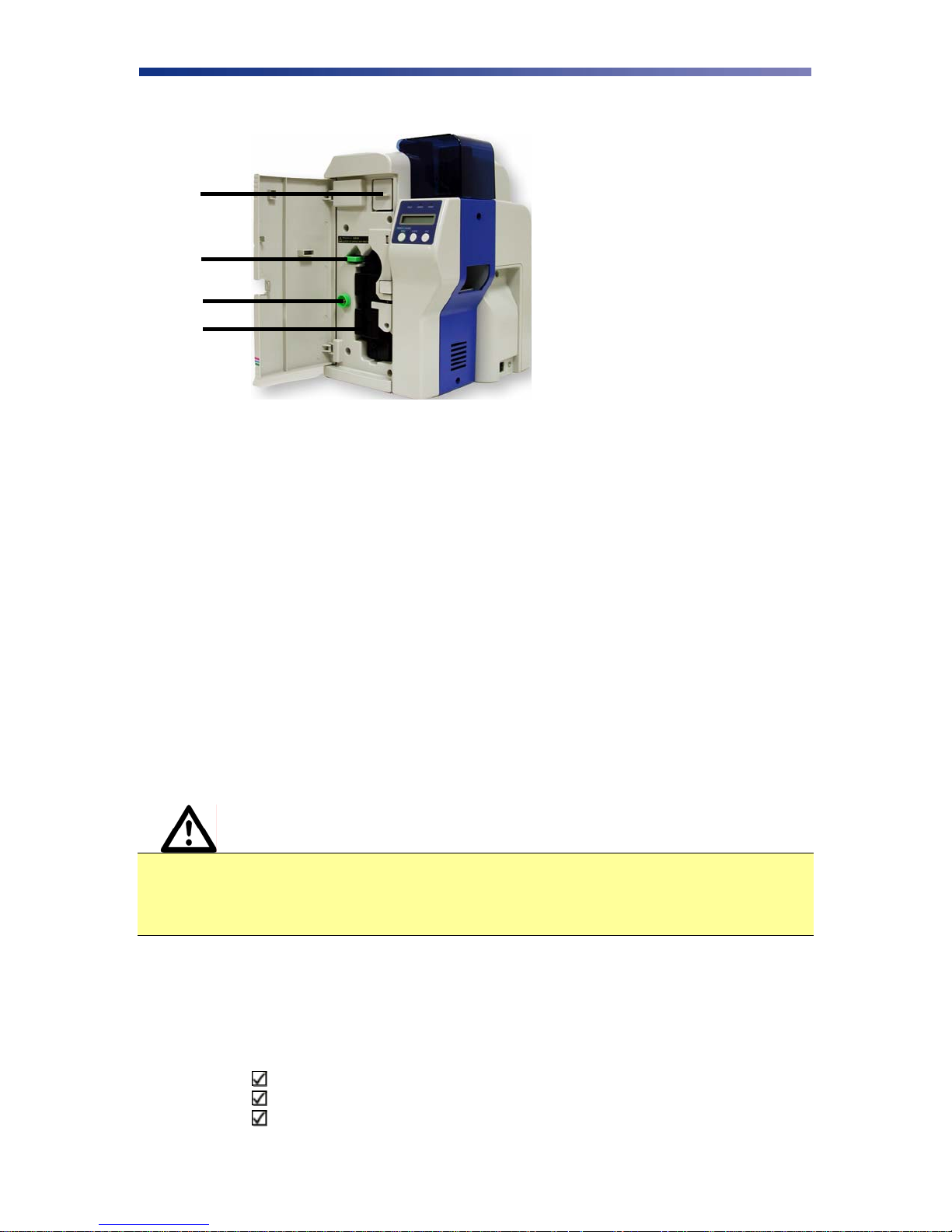
2.1.5 Front Access Panel
A
B
C
D
Figure 2-4: Front access panel
A. Input Roller Module
Removes dust particles from the top and bottom of the card as it feeds into the
printer.
B. Green Retaining Lever
Prevents the ribbon cartridge from being removed.
C. Manual Rotation Knob
Manually advance the rollers.
D. Ribbon Cartridge
Print sharp, colorful images onto various types of cards.
2.2 Unpacking the Printer
Follow these steps to unpack the printer. Be sure to select a location that meets the general
requirements as stated above.
Caution IMPORTANT! The printer must be placed on a level surface, in a dust free
environment. It is essential to be able to access the printer from all sides for its
installation. It is also recommended that you have one or more persons to assist
with unpacking the printer.
1. Place the shipping carton on a firm level surface. While unpacking, inspect the carton to
ensure no damage occurred during shipping.
2. Remove the printer and carton components from the packing box.
3. Open the accessory box and verify the following items are included:
User’s Guide
Power Supply Cord
Empty Bobbin for Ribbon
7
Page 12

Card Weight
Eject Card Box
Ribbon (Refer to Chapter 2.3: Loading The Ribbon)
Ribbon Cartridge
Printer Driver CD
Warranty Registration Card
If any items are missing, please contact your authorized reseller.
Note Keep all packing material in case you need to move or re-ship the printer.
4. Remove all packing tape.
Figure 2-5: Remove tape
5. Open the front access panel by depressing the release button and lift the green retaining
lever. Gently remove the ribbon cartridge by sliding it toward the front of the printer.
Figure 2-6: Front access panel
8
Page 13

6. Remove the print head packing material from the ribbon cartridge.
Figure 2-7: Remove print head packing
2.3 Loading The Ribbon
The PR53xx series printers can accept various ribbon types. Depending on your model, the
following are available ribbon types:
Ribbon Type
K
KO
YMC
YMCK
YMCK02
YMCK03(3BP)
YMCK0K2
Note IMPORTANT! Nisca card printers require special ribbons to function properly.
For this reason, use only genuine Nisca ribbons from Nisca authorized resellers.
Use of non Nisca ribbons may void the warranty and reduce the print quality and
durability.
PR5300 PR5310 PR5350 PR53LE
• • • •
• • • •
• • •
• • •
• •
• •
• • •
9
Page 14
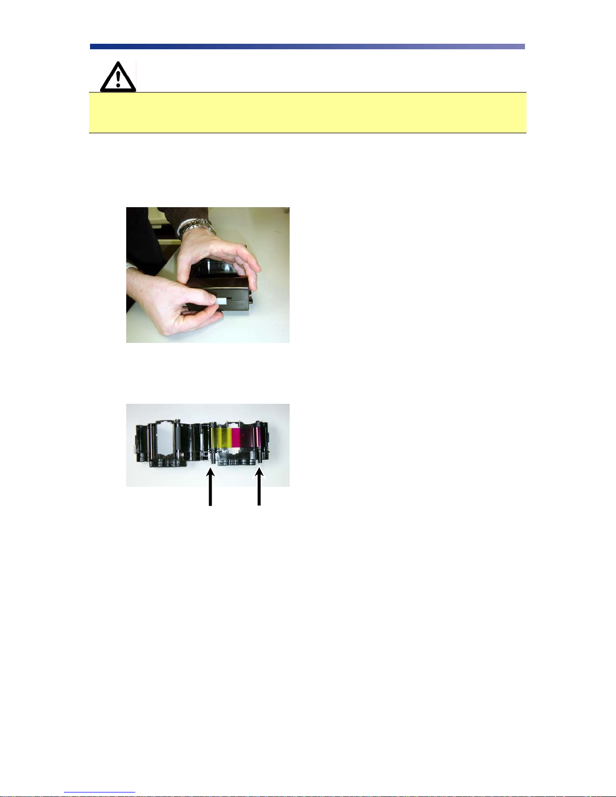
Caution IMPORTANT! To prevent damage to the print head, you must press the
Ribbon Change button BEFORE removing the ribbon cartridge. Refer to figure
2-3: Printer LCD panel.
Initially, the print head has been retracted at the factory for shipment so you do not have to press
the Ribbon Change button for initial setup. To load the ribbon, follow these steps:
1. Open the ribbon cartridge by sliding the release lever to the left.
Figure 2-8: Open ribbon cartridge
2. Remove new ribbon from its packaging and place on the supply side of the ribbon
cartridge.
Supply Side Take up Side
Figure 2-9: Load new ribbon
3. Locate the empty ribbon bobbin packaged with the printer accessories and place on the
take up side of the ribbon cartridge.
10
Page 15
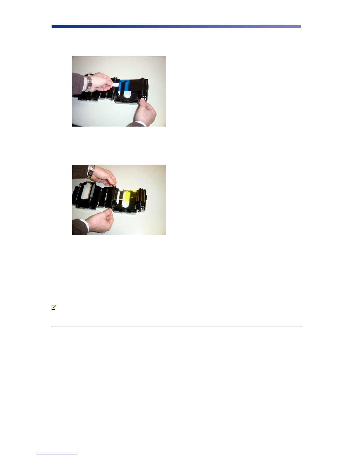
4. Remove the tape and pull the released ribbon towards the take up bobbin. Attach the tape
to the bobbin making sure the ribbon is centered on the bobbin.
Figure 2-10: Remove tape
5. Advance the takeup bobbin 2-3 turns to verify that the ribbon is properly seated on the
bobbin and all slack has been removed from the ribbon.
Figure 2-11: Advance bobbin
6. Close the ribbon cartridge and slide the release lever to the right ensuring the cartridge is
securely locked.
7. Slide the ribbon back into the printer and lower the green retaining lever to lock the
ribbon cartridge in place.
8. Close front access panel.
Note Store ribbons in a cold, dark place. Maximum storage period is 6 months after
delivery if they are kept in an environment of 25º C (77º F), 50% RH. Beyond
this time frame, print quality may be affected.
11
Page 16
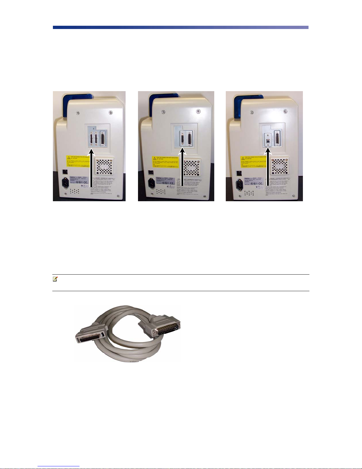
2.4 Connecting The Printer
This section describes how to connect the printer to a power source and to a PC that runs the
printer driver. Depending on the model you purchased, it can be connected either by SCSI,
Parallel, or USB:
SCSI
Parallel USB
Figure 2-12: Printer connection types
To connect the printer to your computer, follow the instructions based on your connectivity.
2.4.1 SCSI Connection
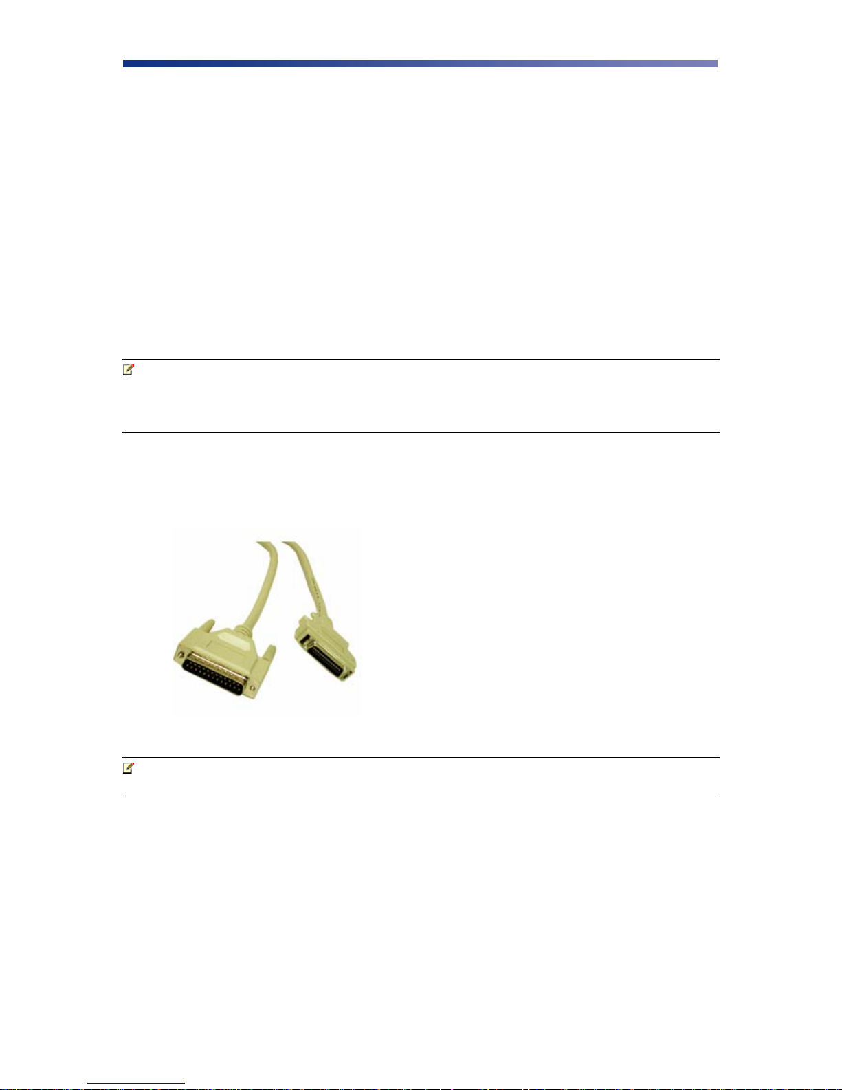
If you are connecting your printer via a SCSI connection, obtain the appropriate interface cable.
Note Use only an external DB25 to 50-pin high density, half pitched Amphenol
connector. TEAMNisca recommends an Adaptec ACK-D2H-1M-ICE.
Figure 2-13: SCSI cable
1. Make sure the computer and printer are turned off.
2. Each SCSI device to be connected in the SCSI chain must be identified with an
individual ID number. There are 7 potential SCSI ID numbers to specify and each SCSI
device must be assigned its own unique ID number. The default SCSI ID number for the
printer is 4.
12
Page 17
3. You can set the ID number in the printer by accessing the User Mode Menu. Press and
hold the Menu button on the LCD panel until it displays “User Mode”.
4. Press the EXE button several times until the SCSI ID sub menu is displayed. Press the
Menu button to enter this menu and select the appropriate ID number using the EXE
button. The numbers can be between 0-7.
5. Select “Return to Normal Mode” with the MENU button and press the EXE button to
return to the “Ready to Print” display.
6. Depending where your printer exists on the SCSI chain will determine the selection of the
terminating switch. If the printer is in the middle of the chain, the terminating switch
should be in the “Off” position. If the printer is at the end of the chain, then the
terminating switch should be set to “On”.
7. Insert the power cord into the power receptacle on the rear of the printer. Plug the other
end into an available wall outlet.
Note The SCSI ID cannot be the same as any other device in your system. SCSI ID 0
is reserved for boot devices and is therefore not recommended for use. The SCSI
interface allows for very high-speed data transmissions. To ensure error free data
transmissions, use the shortest cable possible.
2.4.2 Parallel Connection
To connect the printer to your computer, obtain the appropriate interface cable. A printer to PC
interface cable is a non standard accessory.
Figure 2-14: Parallel cable
Note Use only a shielded, Type C, IEEE 1284 parallel port cable up to a maximum of
6.5 feet long.
1. Make sure the printer and computer are turned off.
13
Page 18
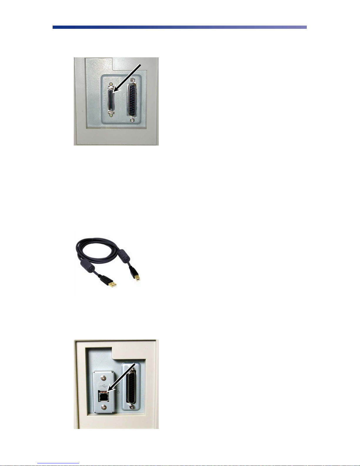
2. Connect the micro centronics connector to the printer’s parallel port, and snap the
fastening clips into place.
Figure 2-15: Parallel port
3. Connect the other side of the cable to the parallel connector on the back of the computer.
4. Insert the power cord into the power receptacle on the rear of the printer. Plug the other
end into an available wall outlet.
2.4.3 USB Connection
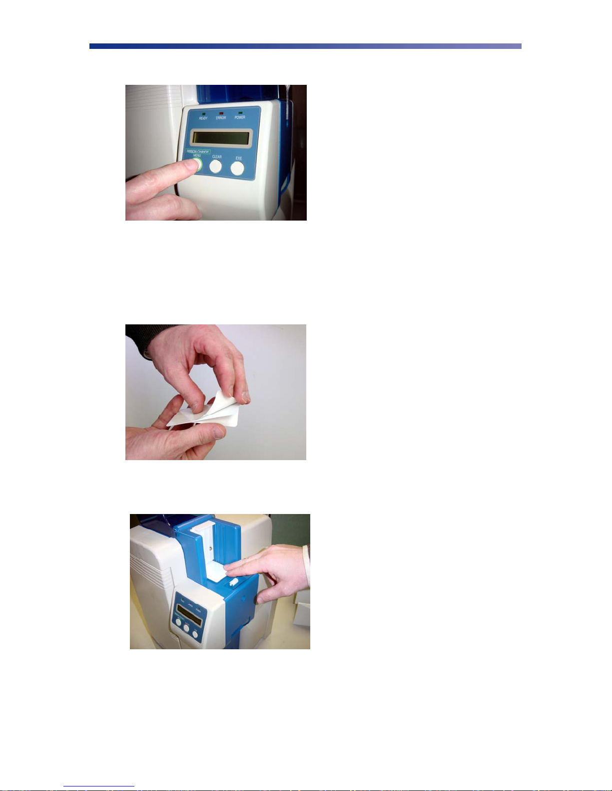
To connect the printer to your computer, obtain the appropriate USB 2.0 cable.
Figure 2-16: USB cable
1. Make sure the printer and computer are turned off.
2. Plug the USB 2.0 cable into the printer.
Figure 2-17: USB port
14
Page 19

3. Plug the other end of the USB cable into the computer.
4. Insert the power cord into the power receptacle on the rear of the printer. Plug the other
end into an available wall outlet.
2.5 Loading Cards
Before you begin printing, you must load blank cards into the printer’s card feeder. You may
load cards while the printer’s power is either on or off. You may also load cards while the printer
is printing. The printer is factory configured to feed and print standard size CR-80 card stock at
30 mil. To adjust the card thickness, see Chapter 2.6: Card Thickness Adjustment. To load
cards, follow these steps:
1. Lift the card feeder door and remove the card weight.
2. Remove a new stack of cards from their packaging. Shuffle the cards but be cautious not to
touch the card surface as dirt from your hands could impair the print quality.
3. Holding the stack of cards by their edges, place the cards into the card feeder between the
guides.
Figure 2-18: Stack cards
4. Always load cards with the primary print side facing up. If inserting cards with a magnetic
stripe, ensure the magnetic stripe is positioned on the bottom and towards the back.
Incorrect positioning will result in encoder write errors.
5. Once the cards are loaded, place the card weight on top of the card stack with the raised
bevel handle facing away from the printer. The card weight increases feeding reliability
primarily when only a few cards are in the card feeder.
6. Close the card feeder door. The cards will automatically feed from the bottom first.
Note Stack the cards evenly to prevent the printer from reporting a “pick up error”.
Always store your card stock in its original packing or in a clean, dust-free
container. Ideally, use cards as soon as possible.
15
Page 20

2.6 Card Thickness Adjustment
When loading cards that vary from the standard size, it is necessary to make a simple adjustment
to the printer. To adjust the card size, follow these steps:
1. Open the card feeder door and remove cards.
2. Loosen the two phillips head screws on the adjustable gate.
Figure 2-19: Adjustable gate
3. Insert a card into the card feeder just under the gate.
4. Lower the gate until it slightly touches the card.
Figure 2-20: Lower gate
5. Raise the gate one half the thickness of the card and tighten the screws.
6. Test the new adjustment by attempting to slide two cards under the gate. If two cards
slide under the gate, the gap width is incorrect and return to step 3. You should not be
able to slide two cards into the gap.
16
Page 21

2.7 Turning on the Printer
Before installing the printer driver and before using the printer, follow these steps to power on the
printer.
1. The computer connected to the printer should be turned off.
2. Make sure cards and printer ribbon have been loaded.
3. Make sure the power cord and printer interface cable is connected.
4. Once the power cord is connected, press the power switch located on the right side of the
printer. The switch will read ‘|’ and not ‘O’.
5. Turn on the computer.
6. Turn on the printer.
2.8 LCD Modes of Operation
2.8.1 Normal Mode
The printer is equipped with an LCD panel that communicates helpful information about the
printer’s operation. Menu selections are made by pressing the corresponding soft button below
the LCD option.
When the printer is first powered on, the printer’s initialization check will briefly appear and the
printer will indicate “PLEASE WAIT, NOW INITIALIZING”. When completed, the green
Ready indicator light will be illuminated. The LED lights work in conjunction with the printer’s
LCD panel to help communicate the status of the printer. The printer will stay in this mode until
it receives a print job or it is turned off.
If the red Error indicator light is illuminated, the printer has encountered an error or attention
condition. Refer to the printer’s LCD panel for information. Also refer to Chapter 4 for
troubleshooting. To erase output data from the printer’s memory, press and hold the Clear button
for 3 seconds. The LCD panel will indicate the printer has been reset and the LCD panel Uill
display “READY TO PRINT” with the Ready light illuminated.
2.8.2 User Mode
Note To view User Mode menu map, see Appendix C.
User Mode operation is used for navigating the various configuration menus. To enter User
Mode, follow these steps to change many of the printer’s settings:
1. Press and hold the Menu button on the LCD panel until “User Mode” is displayed.
2. Once you enter User Mode, press the Menu button to advance through the menus and
press the EXE button to execute the instruction.
17
Page 22

2.8.3 Functions of the User Mode
Card Count
Indicates the current card count and is used to monitor card production. Pressing the
Clear key resets the value to 0.
Total Count
Indicates the total number of cards printed and cannot be reset. This value helps give the
operator a measure of the printer’s overall work cycle.
Color Adjustment
Setting allows the user to adjust the intensity of Yellow, Magenta and Cyan. Each value
can be adjusted with the range of ±3.
Black Adjustment
Increase the value for a more crisp fine line or decrease the value if a bold line smudges.
Error Buzzer
Selection is either on/off. An audible alarm sounds when errors such as “Cover Open” or
“Card Empty” occur if the selection is turned on.
Ribbon Type
Select the appropriate ribbon type – refer to the label on the ribbon and the various ribbon
types. See Chapter 2.3: Loading The Ribbon on page 9. Setting the appropriate ribbon
type is required for proper operation.
SCSI ID Select
Select the appropriate SCSI ID. See Chapter 2.4.1: SCSI Connection on page 12.
ROM Version – Optional Devices
If an encoder ROM display is included in the ROM version menu, an internal encoder is
connected. If no encoder is installed, this display will be blank.
ROM Version – Optional Encoder Type
4 digit alpha-numeric value displayed on the lower right side of the “encoder ROM”
which shows the type of the encoder connected.
ROM Version – Firmware Version Information
The printer’s current firmware version. The firmware version can be updated in order to
support additional controls. See Chapter 3.8: Updating The Firmware on page 27.
Printer Status – System Environment
Set these functions according to the system being used.
MENU FUNCTION
Parity Set Set On/Off for the parity.
Encode Type Select Hi-Co or Low-Co.
Encode First When set to on, encoding is done before printing.
Encode Mode Determines encoding orientation.
Encode Reject Selects rejected hopper.
18
Page 23

IC-R/W Error Mode Controls the display of error messages on the LCD panel.
EXE Key Print Set to on to have data in the memory printed.
Print Retry Set to on to have card with error re-outputted.
Parallel Print Set to on to process multiple cards simultaneously.
Card Eject Face Select which side of the card to eject.
Print Area Select printable area on the card. Full edge of 0.5 mm from all
edges of a card.
Note Depending on the printer’s hardware configuration, some of these functions may
not be available.
19
Page 24

CHAPTER
3.
Maintenance
Your Nisca PR53xx series printer is built to require a minimum amount of maintenance.
Nevertheless, there are a few procedures you need to perform on a regular basis or as needed to
ensure maximum performance.
Caution IMPORTANT! As with any electronic device, internal components of the
printer, such as the print head, may be damaged if exposed to static electrical
discharges. Make positive contact with the bare metal chassis of the printer with
your hand prior to touching any internal electrical components.
Following is a minimum cleaning requirement schedule:
CLEANING SCHEDULE CLEANING TOOL
Takeup Roller 10,000 prints
Input Rollers 2,000 prints
Card Flip/Turn Transport
Rollers
Print Unit Rollers 10,000 prints Alcohol Swab
Print Head 2,000 prints Alcohol Pen
You can check the number of prints by referring to the menu map in Appendix C.
3.1 Basic Automated Cleaning
Basic automated cleaning is recommended after every ribbon change. For this maintenance
procedure, you will need a printer Cleaning Card available from your authorized reseller. The
Cleaning Card contains adhesive backing causing dust particles and debris on the rollers to adhere
to the card. It is recommended to only use genuine Nisca Cleaning Cards.
10,000 prints
Alcohol Swab
Alcohol Swab
Alcohol Swab
20
Page 25
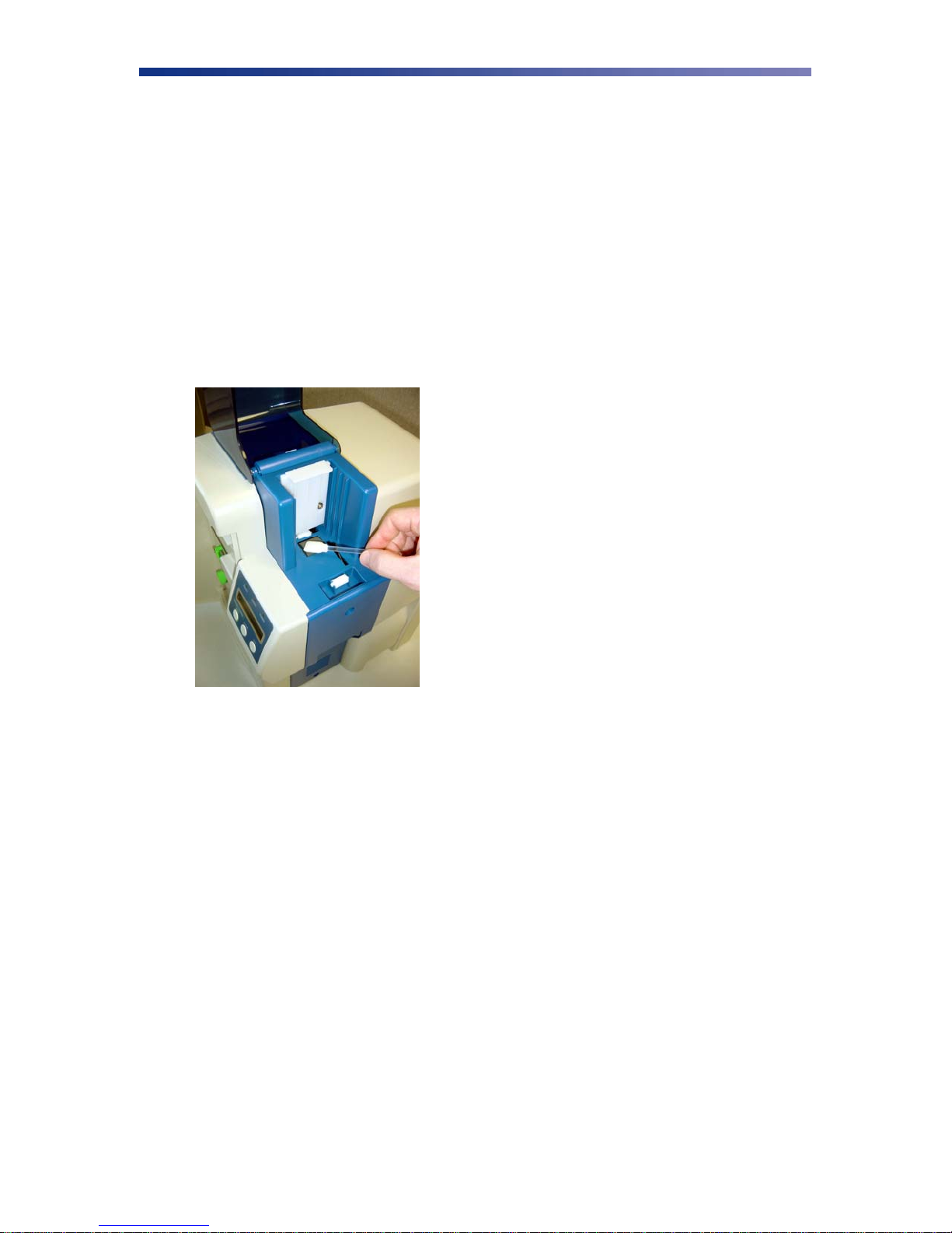
1. Enter User Mode by pressing and holding the Menu button for 3 seconds.
Figure 3-1: Entering User Mode
2. Press EXE and then use the Menu button to navigate to the Cleaning sub-menu. See User
Mode Menu Map in Appendix C for navigation assistance.
3. Open the card feeder door and remove any blank cards.
4. Remove the protective paper backing from both sides of the cleaning card.
Figure 3-2: Remove protective backing
5. Insert the Cleaning Card into the feed gate until the card stops.
Figure 3-3: Insert cleaning card
6. Press the EXE button to begin the cleaning process.
7. Remove the card when the process is completed and discard.
21
Page 26
3.2 Manual Cleaning
As you use your printer, dust and other particles may accumulate inside the printer before you
actually need to replace the ribbon. To maintain a consistent print quality, manual cleaning
procedures should be performed periodically. The following identifies areas needed for manual
cleaning.
3.3 Cleaning the Takeup Roller
The takeup roller automatically feeds the cards from off the bottom of the stack into the printer.
The takeup roller should be cleaned every 2,000 prints to help prevent card jams and maintain the
best print quality.
1. Open the card feeder door, remove any blank cards, and locate the takeup roller.
Figure 3-4: Clean the takeup roller
2. Use an alcohol swab to clean the roller. Use your fingertips to move the roller back and
forth while cleaning.
3. After the roller has been cleaned and is completely dry, reload the cards into the card
feeder and close the card feeder door.
3.3 Cleaning the Input Rollers
The input roller module removes dust particles from the top and bottom of a card as it feeds into
the printer. Cleaning the rollers helps prevent card contamination, thus allowing for a higher
print quality. The input rollers should be cleaned if your prints start showing bumps, speckles or
debris on the printed surface.
22
Page 27
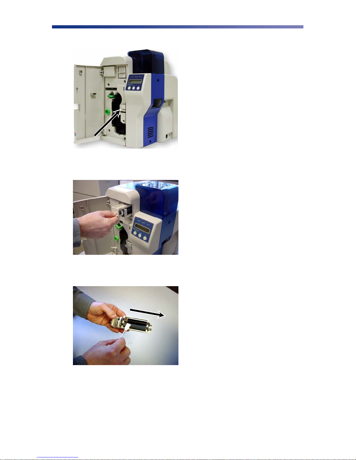
1. Open the front access panel by depressing the release button.
Figure 3-5: Open front access panel
2. Grasp the input roller module tab and pull it out of the printer.
Figure 3-6: Grasp input roller
3. Clean the rollers with an alcohol cotton swab in the direction pictured.
Figure 3-7: Cleaning the rollers
4. Once the dust and debris is cleaned from the rollers, place the input roller module back
into the printer. Push in until it hits the stops and close the front access panel.
23
Page 28
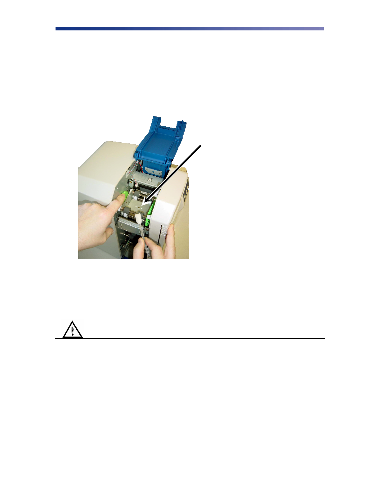
3.4 Cleaning the Flip/Turn Transport Rollers
1. Power off the printer and remove the power cord.
2. Remove the phillips screw on the left side of the printer to open the print unit door. Open
the top cover and manually rotate the flip/turn transport roller 180° by moving the unit
counter-clockwise.
3. Advance the green knob and use an alcohol swab to clean the rubber and white plastic
rollers.
Flip/Turn Transport Rollers
Figure 3-8: Advance flip/turn rollers
4. After cleaning the flip/turn transport rollers, proceed to cleaning the print unit rollers in
the next section.
3.6 Cleaning the Print Unit Rollers
Warning
IMPORTANT! Power off the printer to prevent electrical shock.
24
Page 29
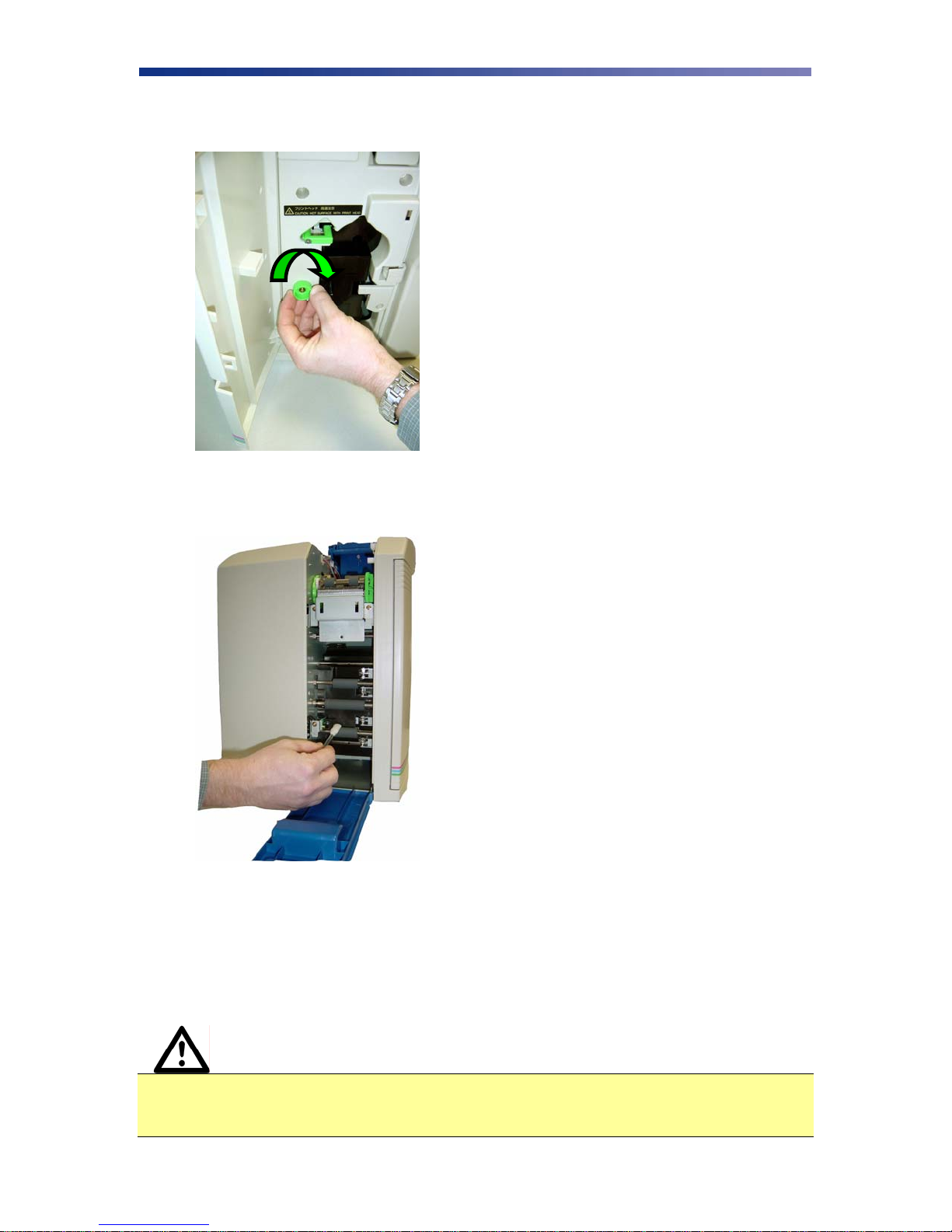
1. With the print unit door still open, turn the manual rotation knob clockwise to advance
the print rollers.
Figure 3-9: Turn rotation knob
2. Clean each of the print unit rollers using a alcohol cotton swab.
Figure 3-10: Cleaning print rollers
3.7 Cleaning the Print Head
This procedure should be performed if you notice a streak on the card where color was not
transferred or every 2,000 prints to maintain a consistent print quality. To clean the print head,
you will need a print head cleaning pen available from your authorized reseller.
Caution IMPORTANT! The print head may be hot. Turn off the power and let the print
head cool before proceeding with this section. Never use a sharp tool or abrasive
object of any kind to clean the print head.
25
Page 30

1. Press “Ribbon Change” on the control panel once to lift the print head. This allows for
removal of the ribbon cartridge.
2. Power off the printer and remove the power cord.
3. Open the front access panel by depressing the release button. Lift the green retaining
lever and remove the ribbon cartridge.
Figure 3-11: Open front access panel
4. Using a phillips screwdriver, remove the retaining bracket.
Figure 3-12: Remove retaining bracket
26
Page 31
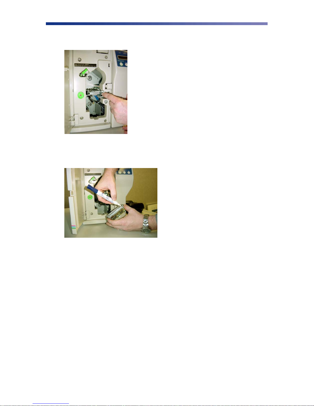
5. Press the metal latch to release the print head and gently slide the print head toward the
front of the printer.
Figure 3-13: Press metal latch
6. Using a print head cleaning pen, firmly wipe back and forth across the surface of the print
head.
Figure 3-14: Using the print head cleaning pen
7. Once the print head is completely dry, reinstall the print head in reverse order.
3.8 Updating the Firmware
The firmware is internal software that controls the operation of the printer. Occasionally, new
firmware versions are released which have updated and/or new features. New firmware updates
can be downloaded from the Nisca website at www.teamnisca.com and loaded into your printer
using the “Download Utility” program. No physical replacement or repair of any parts is
required, so this process is simple. Download the appropriate file(s) based on your interface and
operating system. If you do not have Internet access and are unable to access these files, contact
your authorized reseller for assistance.
27
Page 32
Caution IMPORTANT! It is critical that all printers, including the Nisca PR53xx series
printer be temporarily removed from LPT1 for the firmware utility to function.
One recommendation is to change the port of all printers from LPT1 to LPT2.
Refer to the following steps to update your firmware:
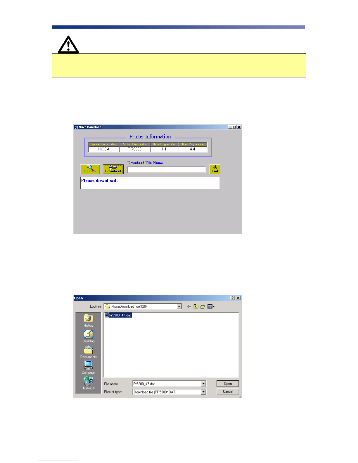
1. Download and install the Firmware Update Utility from www.teamnisca.com.
2. Run the firmware update program. The firmware update utility program will appear:
Figure 3-15: Firmware update program
3. From the download utility program, click on the search button. This finds the printer
attached to your computer.
4. Click the Download button and go to the folder in which you saved the update file, select
it, and click Open.
Figure 3-16: Selecting firmware update file
28
Page 33

5. A dialog box will ask you to confirm executing the update. Click Yes. This will begin
the firmware update process that will only take a few minutes.
6. Click end to exit the program and turn the printer power off for a few seconds and back
on. You may verify the status of the new firmware version by entering User Mode on the
printer. See Appendix C for further assistance on checking the ROM version.
29
Page 34
CHAPTER
4.
Troubleshooting
This chapter offers explanations to potential problems you may experience with your PR53xx
series printer. The LCD panel will alert the operator and will display the error condition. The
suggestions in this chapter should, in most cases, solve the problem. If you still have difficulty
after trying these suggestions, contact your authorized reseller for technical assistance.
Note Prior to contacting your authorized reseller for assistance, make note of the error
message along with the error code located under the actual description.
In most cases, press the Clear button after identifying the error to return the printer to the Ready
to Print status. If the message “Cannot Recover/Please Reset” appears, press and hold the Clear
button for more than 3 seconds while the printer resets.
4.1 Interpreting General LCD Messages
LCD SCREEN MESSAGE PROBABLE CAUSE ACTION
Initializing The printer is performing an internal
test before use.
Ready to Print The printer will accept data and
begin printing.
Card Empty Indicates there is not an adequate
supply of cards in the printer’s
feeder.
Front access panel is Open The front access panel on the printer
is open or incorrectly closed.
Top Cover is Open The cover to the flip/turn unit is
open.
Temperature out of Range Temperature of the print head is out
of range.
Wait for the Ready to Print
message.
Add more cards to the input
feeder.
Close the front access panel
and press the Clear button to
return the printer to the
ready state.
Close the top cover until it
snaps closed.
Turn the printer off and
allow the print head to cool.
Turn the printer back on and
wait for the Ready to Print
message.
Encoder Write Error Data cannot be written or read from
30
the card’s magnetic stripe
Check the cards are loaded
with the magnetic stripe in
the correct orientation.
Page 35

LCD SCREEN MESSAGE PROBABLE CAUSE ACTION
Check whether high or low
coercivity cards have been
specified.
Verify no debris is on the
card and replace with
another card.
Print Card does not Exist An error has occurred during dual
side printing.
Please Check Ribbon This error occurs when the printer
detects a problem with the ribbon.
Ribbon Empty The printer ribbon has run out. Install a new ribbon. See
Ribbon Type Incorrect The printer ribbon installed in the
printer does not match the ribbon
type specified in the printer settings.
Ribbon Wind up miss The ribbon is not installed correctly;
the ribbon transport is dirty; an
improper card was used; the
engagement teeth on the bobbin are
broken.
Press the clear button and
reprint the card.
Press the Ribbon
Change/Menu button to
retract the print head.
Remove, inspect, or replace
the ribbon using the
instructions provided in
Chapter 2.3.
Verify the settings in the
Ribbon Type sub-menu
match the ribbon installed in
the printer.
Chapter 2.3.
Enter User Mode on the
printer and change the
settings in the Ribbon Type
sub menu to match the
ribbon type installed in the
printer i.e. YMCK,
YMCKO, YMCKOK, etc.
Verify the ribbon installation
using the instructions in
Chapter 2.3. If the ribbon
has broke, clear tape may be
used to affix it back onto the
bobbin.
Clean the flip/turn transport
using instructions in Chapter
3.5.
Verify you are not trying to
double print a card.
Inspect the bobbin. If the
bobbin is damaged, replace
it.
4.2 Interpreting LCD Jam Messages
If a card becomes jammed inside the printer, the LCD will indicate the approximate location of
where it is jammed. Try to eject the jammed card first by pressing the Clear button. If the card
does not eject automatically, refer to the following table for a list and cause of the LCD message.
Many jams can be fixed by keeping the rollers clean. See the PR53xx series printer block
31
Page 36
diagram at the end of this chapter for clarification of the areas for jams. Refer to Chapter 3 for
cleaning procedures.
Warning
IMPORTANT: Power off the printer to avoid electrical shock when
clearing jams.
LCD SCREEN MESSAGE PROBABLE CAUSE ACTION
Card Jam Feeder Area The printer in unable to feed a
card from the card Feeder.
Open the Card Feeder door
and remove cards.
Verify cards are appropriate
thickness.
Clean the input rollers.
Be sure to use the
appropriate card weight.
Adjust the card gate. See
Chapter 2.6 for Card
Thickness Adjustment.
Card Jam F Turn A card is jammed between the
input rollers and the flip/turn unit.
Card Jam Print Area A card is jammed between the
flip/turn unit and the print unit.
Open the cover to the
flip/turn unit.
Use the green dial to
advance the card in a
position easier for removal.
If this error occurs again,
clean the rollers in the
flip/turn unit.
Press the Ribbon
Change/Menu button and
remove the ribbon.
Open the flip/turn cover and
use the green dial to remove
the card.
If you can’t remove the card,
remove the phillips screw to
the print door.
Open the print door and
remove the card using the
manual green dial to
advance the card in a
position easier for removal.
If this error occurs again,
clean the rollers in the print
unit. See Chapter 3.
Card Jam Encode Area A card is jammed between the
Card Jam Unknown A jam occurred that is unknown
32
flip/turn unit and the encoder.
to the printer.
Press and hold the clear
button to reset the printer.
If the card does not eject
automatically, remove it
manually.
Inspect all areas of the
printing path.
Page 37

LCD SCREEN MESSAGE PROBABLE CAUSE ACTION
Press and hold the clear
button to reset the printer.
Card Jam Remove the Card A card is jammed in the printer. Press and hold the clear
button to reset the printer.
If the card does not eject
automatically, remove it
manually.
Refer to the block diagram at
the end of this section for
jam areas.
4.3 Card Appearance Issues
CARD APPEARANCE PROBABLE CAUSE ACTION
Color discoloration; Color Drop
Abnormal coloring of anamorphous area
A thin line or scratch appears along the
entire card length
Most likely due to debris on
the card, dust inside the
printer or dirty rollers.
Grease from fingertips on
the surface of the card.
Print head is dirty. Clean the print head.
Ensure cards free of
debris.
Ensure printer is in a
clean area.
Clean all rollers.
Do not touch surface of
the card with your
fingers. Hold card by
its edges only.
If problem persists, you
may need to replace the
print head. Avoid dirty
cards because they can
damage the print head.
33
Page 38
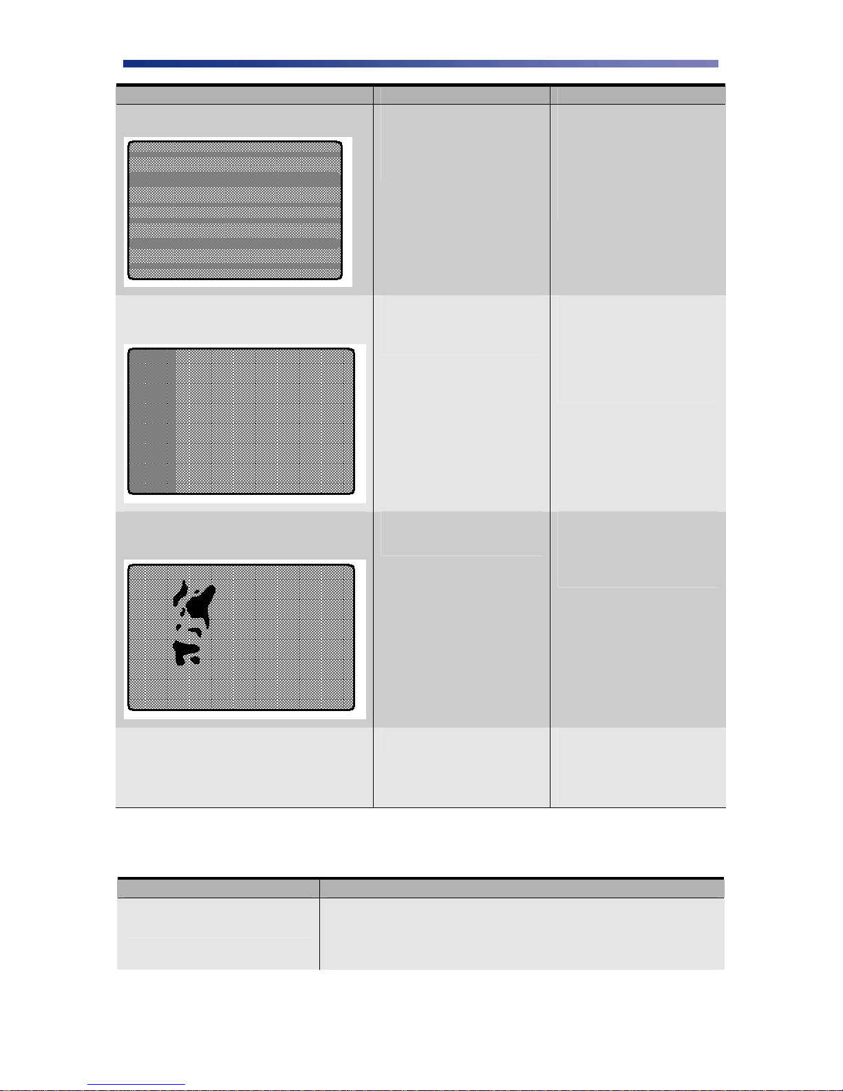
CARD APPEARANCE PROBABLE CAUSE ACTION
Random bands or streaks.
The color of the printed image suddenly
changes in the middle of the card
Print head is stained. Print
head may be need replaced if
more than 20,000 prints have
been made.
The ribbon has been
removed without releasing
the print head.
Clean the print head.
Replace, if necessary.
Clean the rollers in the
print block area. See
Manual Cleaning,
Chapter 3.2.
Remove the ribbon by
pressing the Ribbon
Change/Menu button.
Verify the correct
ribbon is specified in
the printer settings.
Unexposed dark area appears on the printed
image
White card; no image printed Incorrect ribbon setting. If a color image is
Material or debris is on the
card.
Try another card and
use only cards specified
by your authorized
reseller.
printed while the ribbon
is set to KO, the card
printed will be blank.
4.4 General Troubleshooting Suggestions
PROBLEM ACTION
Printer doesn’t seem to work at
all.
Verify the power cord is plugged in securely on both ends and
the printer is on. Confirm power is applied by pressing the
power switch. Also be sure the printer is ready by verifying the
LCD light above the Ready LED is illuminated.
34
Page 39

PROBLEM ACTION
Data cannot be transmitted to the
printer.
Setting the Parallel Port to ECP
Make certain the printer cable is securely connected to the back
of the printer and computer.
SCSI Interface:
• Verify the SCSI ID is not conflicting with other device(s).
• Cycle the power by turning the printer off and then back
• Verify the position of the terminating switch. The
Parallel Interface:
• Cycle the power by turning the printer off and then back
You must change the parallel port mode through your system
"BIOS" or setup screen. The system BIOS is generally entered
by holding down a specific key while the computer is booting
up. This key will differ depending on which brand of computer
you have, but is often specified on screen during initial startup.
For example, a line such as "Press <DEL> key if you want to
run SETUP” may appear.
Once you have entered the BIOS, use the on-screen directions to
locate the parallel port option and change it to ECP. Also, check
if your particular BIOS provides an option for enab ling a DMA
channel. If so, enable this as well. Once changed, save the
BIOS settings and reboot.
on.
terminating switch should be in the on position if the
printer is at the end of the SCSI chain and off in all other
positions.
on.
Nisca Print Spooler Error Ensure “Enable bi-directional support” is activated.
4.5 Where to get additional help
If you work with an authorized Nisca distributor or value added reseller, contact your reseller for
assistance. You may also contact us at one of the following sources:
Telephone: (732) 271-7367
Sales email: [email protected]
Technical Support email: [email protected]
Website: www.teamnisca.com
35
Page 40

4.6 PR53xx Series Block Diagram
Flip/Turn
Print
Unit
Feeder
Encoder
36
Figure 4-1: Series block diagram
Page 41

APPENDIX
A.
PR53xx Series Printer Specifications
Printing System
300 dpi, 24 bit continuous tone printing,
16.7 million colors, 256-grayscale, 8bit
PR5300 PR5310 PR5350 PR53LE
•
•
•
•
Printing Method
Thermal transfer dye-sublimation
Print Media
Card PVC or polyester cards with polished
PVC finish
Medium Size
Card width/length: CR-80, 2.125”
(54mm) x 3.375” (85.6mm)
Card width/length: CR-79, 2.051”
(52.1mm) x 3.303” (83.9mm)
Medium Thickness
0.020” (20mil) to 0.050” (50mil) /
0.508mm to 1.72mm
Print Area
Edge to Edge
Input Feeder Capacity
Up to 100 cards
Output Feeder Capacity
Up to 100 cards
Image Memory
8 MB with parallel processing, four
memory modes
16 MB with parallel processing, four
memory modes
•
•
•
•
•
•
•
•
•
•
•
•
•
•
•
•
•
•
•
•
•
•
•
•
•
•
•
•
•
•
•
•
•
•
•
•
37
Page 42

Display
LCD 16 character 2-line display
shows printer status and diagnostic
prompts
Interface
USB 2.0
Parallel
SCSI II
Dimensions
16.57” (H) x 10.66” (W) x 13.03” (D)
(421mm x 271mm x 331mm)
Weight
28.6 lbs. / 13 kg
Operating Temperatures
65 to 80º F / 18 to 27º C
Power Source
100 ~ 240 Volts AC, 50 ~ 60 Hz auto
switching
PR5300 PR5310 PR5350 PR53LE
•
•
•
•
•
•
• •
•
•
•
•
•
•
•
•
•
•
•
•
•
•
•
•
•
•
•
Agency Listing
UL, CE, FCC
Driver Compatibility
Microsoft Windows®
Warranty
2 year return to depot service printer
warranty; 1 year unlimited prints print
head warranty
Options
PR5302 Laminator
PR5301 Magstripe encoder
RFID Encoding (read/write, ready
only
Contact IC Chip
•
•
•
•
•
•
•
•
•
•
•
•
•
•
•
•
•
•
•
•
•
•
38
Page 43
APPENDIX
B.
Printer Configuration
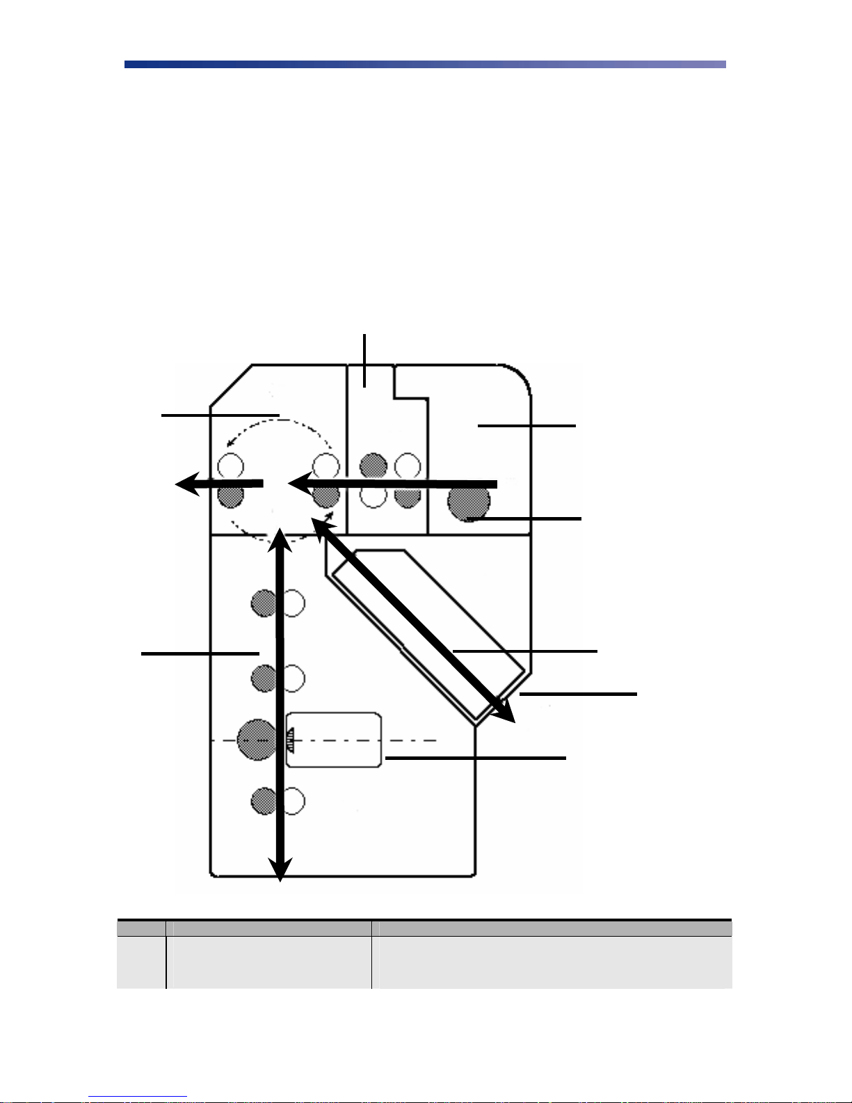
B
D
C
A
H
G
F
E
ITEM NAME DESCRIPTION
A Card Feeder The cards automatically feed from off the bottom of the
39
stack. The slot is 1.5 times the thickness of the card to
Page 44

ITEM NAME DESCRIPTION
prevent double feeding.
B Input Roller Module Removes any debris from the surface of the card prior
to entering the print unit.
C Flip/Turn Unit This unit flips the card over and switches the printing
path from printed, rejected or encoded.
D Print Unit The card moves through this unit as the color and
protective coating is applied. The print head is mounted
perpendicularly to the print unit and is pressed against
the surface of the card.
E Print Head The component of the printer that actually does the
printing. This component is fragile and must not be
bumped or touched with anything other than a cleaning
pen.
F Card Rejection The printer will automatically reject cards if there is a
printing error, encoding error, or if a card is left in the
printer after a job is cancelled or printer restarted.
G Encoder Space (Optional) This is for the optional encoder. If an encoder is
installed, encoding, your computer performs reading,
and verification.
H Takeup Roller This roller feeds the card into the printer.
40
Page 45

APPENDIX
C.
C-1 User Mode Menu Map~ PR5300/PR5310
USER MODE
MAIN MENU
Card Count Image Setup — Entry Colo r Adjustment —
Total Count Color Adjustment ¬ Yellow
Image Setup ¬ Black Print Mode
Error Buzzer
Ð On / Off
Ribbon Type ¬ Return to Normal
Printer Cleaning ¬ Return to Parent
Printer Status ¬ Return to Parent Menu
ROM Version ¬
Setup Data Reset
Return to Normal
Mode
IMAGE SETUP
MENU
Ð High Speed / High
Quality
Image Data Print Cyan
Mode
Menu
COLOR
ADJUSTMENT
MENU
Entry
Ð Adjustment
Magenta
Ð Adjustment
Ð Adjustment
Black
Ð Adjustment
Return to Normal Mode
Ribbon Type —
Entry
Printer Ribbon
Ð Ribbon Selection
Return to Normal
Mode
Return to Parent
Menu
RIBBON TYPE
MENU
41
Page 46

C-1 User Mode Menu Map ~ PR5300/PR5310 (continued)
PRINTER
CLEANING
MENU
Remove Normal Cards Printer Status —
Set Cleaning Card Memory Mode
Return to Normal
Mode
Print Area
PRINTER
STATUS MENU
Entry
Ð Mode selection
Encoder Type
Ð Lo-Co / High-Co
Encode First
Ð On / Off
Encode Mode
Ð Card side selection
Encode Reject
Ð Hold / Reject
Exe Button Print
Ð On / Off
Print Retry
Ð On / Off
Parallel Print
Ð On / Off
Card Eject Face
Ð Up / Down / No
effect
Ð Margin selection
Return to Normal
Mode
Return to Parent
Menu
ROM VERSION
MENU
Base Program Setup Data Reset —
Main Program Setup Data Reset
Head Code Return to Normal
Encoder Unit Return to Parent
Return to Normal
Mode
Return to Parent
SETUP DATA
RESET MENU
Entry
Finish
Mode
42
Page 47

C-2 User Mode Menu Map~ PR5350
USER MODE
MAIN MENU
Ready to Print
Removable Ribbon
Card Count Color Adj ustment ¬ Yellow
Total Count Black Print Mode
Image Setup ¬ Gamma 0 Select Cyan
IMAGE SETUP
MENU
Image Setup — Entry Color Adjustment —
Ð High Speed / High
Quality
COLOR
ADJUSTMENT
MENU
Entry
Ð Adjustment
Magenta
Ð Adjustment
Ð Adjustment
RIBBON TYPE
MENU
Ribbon Type —
Entry
Printer Ribbon
Ð Ribbon Selection
H Roller Ribbon
Return to Normal
Mode
Error Buzzer
Ð On / Off
Ribbon Type ¬ Image Data Print Return to Normal Mode
Printer Cleaning ¬ Return to Normal
ID Select
Ð SCSI or USB ID
Printer Status ¬
ROM Version ¬
Setup Data Reset
Return to Normal
Mode
Sharpness Adjust
Ð 0
Mode
Return to Parent
Menu
Black
Ð Adjustment
Return to Parent Menu
Return to Parent
Menu
o
43
Page 48

C-2 User Mode Menu Map ~ PR5350 (continued)
PRINTER
CLEANING
MENU
Remove Normal Cards Printer Status —
Set Cleaning Card Memory Mode
Return to Normal
Mode
PRINTER
STATUS MENU
Entry
Ð Selectable / Non
Selectable
Parity Set
Ð On / Off
Encoder Type
Ð Lo-Co / High-Co
Encode First
Ð On / Off
Encode Mode
Ð Card side selection
Encode Reject
Ð Hold / Reject
IC-RW Error Mode
Ð Error Top
Exe Key Print
Ð On / Off
Print Retry
Ð On / Off
Parallel Print
Ð On / Off
Card Eject Face
Ð Up / Down / No
effect
Print Area
Ð Edge to Edge
Return to Normal
Mode
ROM VERSION
MENU
Base Program Setup Data Reset —
Main Program Setup Data Reset
Head Code/Number Return to Normal
Serial Number Return to Parent
Encoder Unit
Return to Normal
Mode
Return to Parent
Menu
SETUP DATA
RESET MENU
Entry
Finish
Mode
Menu
44
Return to Parent
Menu
Page 49

C-3 User Mode Menu Map~ PR53LE
USER MODE
MAIN MENU
Card Count Image Setup — Entry Colo r Adjustment —
Total Count Color Adjustment ¬ Yellow
Image Setup ¬ Gamma 0 Select Magenta
IMAGE SETUP
MENU
COLOR
ADJUSTMENT
MENU
Entry
Ð Adjustment
Ð Adjustment
RIBBON TYPE
Ribbon Type —
Entry
Printer Ribbon
Ð Ribbon Selection
Return to Normal
Mode
MENU
Error Buzzer
Ð On / Off
Ribbon Type ¬ Image Data Print
Printer Cleaning ¬ Return to Normal
USB ID Select
Ð EXE: Print
Printer Status ¬
ROM Version ¬
Setup Data Reset
Ð CLR+EXE
Return to Normal
Mode
Sharpness Adjust Cyan
Ð Adjustment
Black
Ð EXE: Print
Mode
Return to Parent
Menu
Ð Adjustment
Return to Normal Mode
Return to Parent Menu
Return to Parent
Menu
45
Page 50

C-3 User Mode Menu Map ~ PR53LE (continued)
PRINTER
CLEANING
MENU
Remove Normal Cards Printer Status —
PRINTER
STATUS MENU
Entry
ROM VERSION
MENU
Base Program
Set Cleaning Card
Ð Please wait…Now
Cleaning
Return to Normal
Mode
EXE Key Print
Ð On/Off
Print Retry
Ð On/Off
Print Area
Ð Edge to Edge
Return to Normal
Mode
Return to Parent
Menu
Main Program
Head Number
Serial Number
Return to Normal
Mode
Return to Parent
46
Page 51
APPENDIX
D.
Parts Replacement
This printer is designed to provide excellent performance over time. In order to maintain your
printer in peek performance, several parts should be replaced on a periodic basis. The following
table outlines these parts and the suggested replacement time frame:
PART NUMBER OF PRINTS TOOLS NEEDED
Input Roller Every 20,000 prints N/A
Print Head Every 20,000 prints Firmware Update Utility
Filter Replacement Every 6 months Phillips screwdriver
D-1 Replacing the Input Rollers
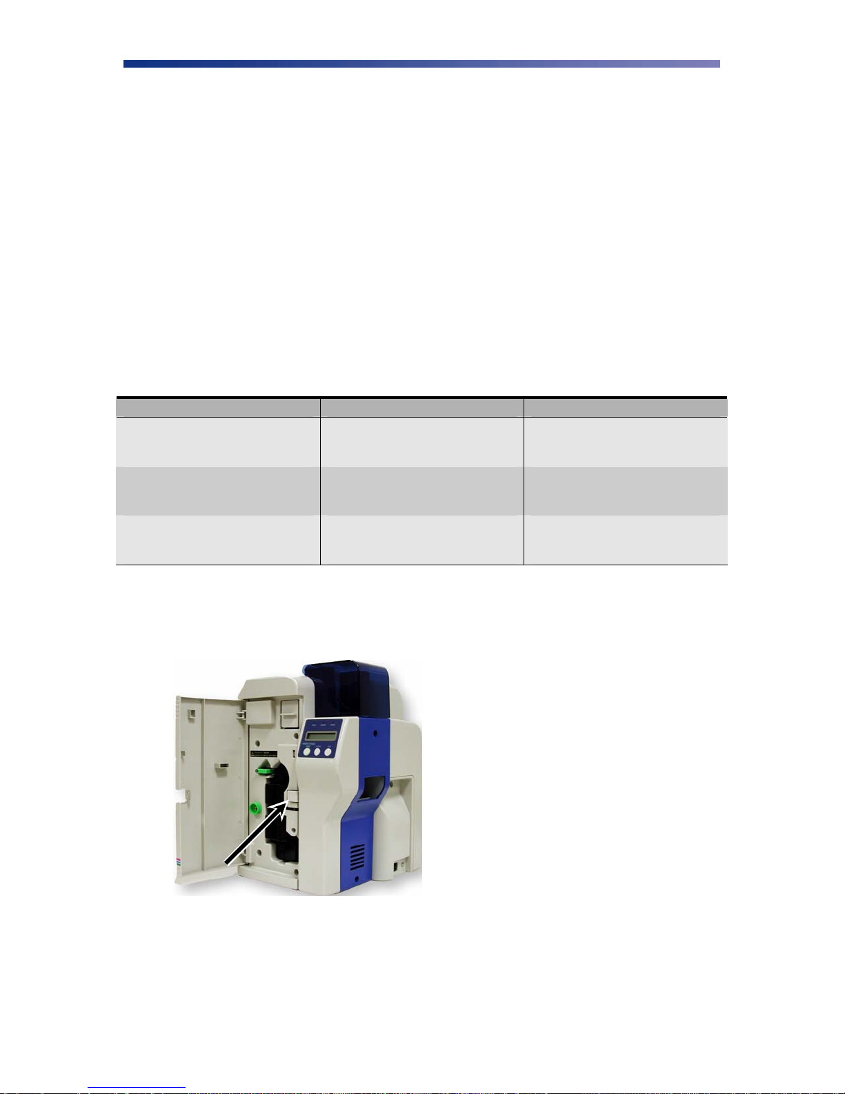
1. Open the front access panel by depressing the release button.
Figure D-1: Open front access panel
47
Page 52

2. Grasp the input roller module tab, and pull it out of the printer.
Figure D-2: Grasp input roller module
3. Clean the new input roller assembly before replacing it back in the printer. Clean with an
alcohol cotton swab in the direction pictured.
Figure D-3: Clean input roller assembly
4. Once the dust and debris is cleaned from the rollers, place the assembly module back into
the printer. Push in until it hits the stops. Close the front access panel.
D-2 Replacing the Print Head
The print head replacement comes with a floppy disk which contains important data. To ensure
the best print quality, the data must be loaded to the printer prior to printing.
Caution IMPORTANT! Be sure the printer has adequate cooling time before proceeding
with this section as the print head may be hot. This component is very sensitive
to static voltage and must not be touched with anything other than a cleaning pen.
1. Press “Ribbon Change” on the control panel once to lift the print head. This allows for
removal of the printer ribbon.
48
Page 53

2. Power off the printer and remove the power cord.
3. Open the front access panel by depressing the release button. Lift the green retaining
lever and remove the ribbon cartridge.
Figure D-4: Open front access panel
4. Using a phillips screwdriver, remove the retaining bracket.
Figure D-5: Remove retaining bracket
49
Page 54
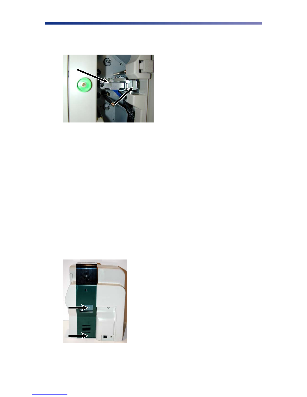
5. Press the metal latch to release the print head and gently slide the print head toward the
front of the printer.
Figure D-6: Release print head
6. Gently remove the pin connector from the bottom of the print head. Because the print
head is very sensitive to static voltage, hold it by the frame only and be careful not to
touch the contact pins.
7. Affix the connector to the new print head and reinstall in reverse order.
8. Insert the floppy disk that came with the print head. This data must be loaded to the print
head before using the printer to ensure the best print quality.
9. Use the firmware update utility as outlined in Chapter 3.8. When prompted for the
update file, be sure to select the file from the floppy disk or sub-directory on your hard
drive where the file is located.
D-3 Replacing the Fan Filter
The fan filter should be replaced every 6 months to ensure proper air flow and should not be
washed with water. Please see your Nisca reseller for the replacement part.
1. Turn off the power to the printer. Remove the two screws on the side panel under the
card hopper using a phillips screwdriver.
Figure D-7: Remove phillips screws
50
Page 55
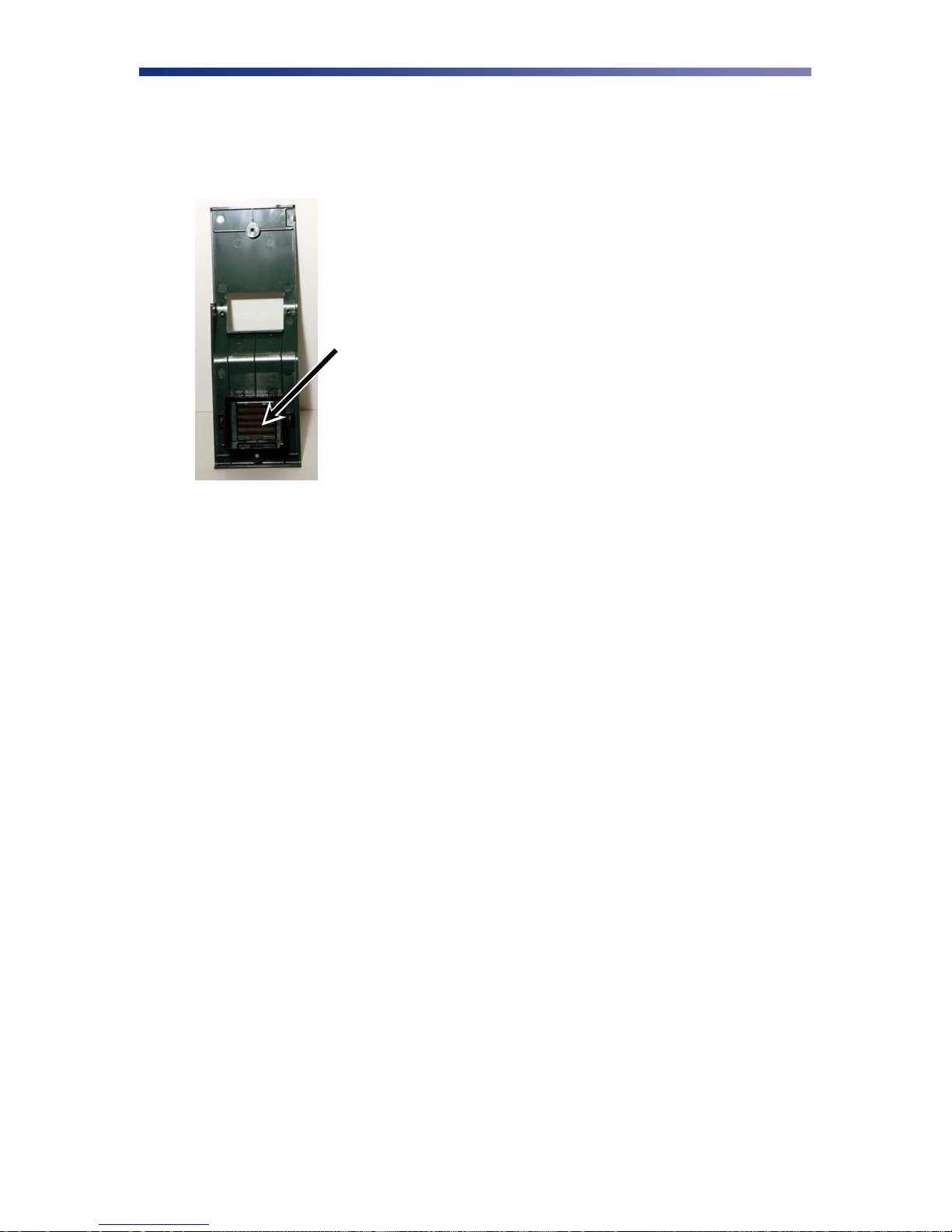
2. Remove the filter from the side panel and insert replacement fan filter. After
replacement, install the side panel in reverse order.
Figure D-8: Remove filter
51
 Loading...