

Page 1
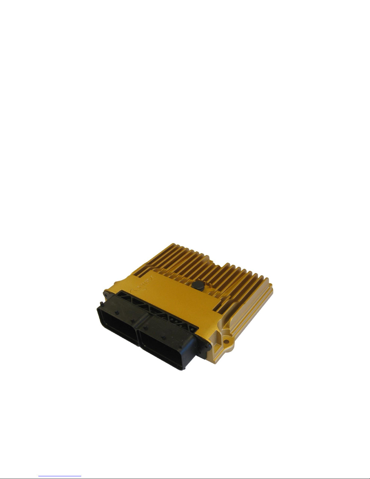
NIRA i7x
Handbook
NIRA i7x Handbook version pA7, August 2016
Page 2

© 2005-2016 Nira Control AB 2
© Copyright 2005-2016
This handbook is protected by copyright laws. It may not be redistributed in
any form without written consent of Nira Control AB.
Release 2016-08-30
The purpose of this handbook is to serve as a guide during installation and
calibration of NIRA i7x. Descriptions, content and specifications in this
handbook may be changed at any time. This handbook could contain errors –
therefore it should not be regarded as a definitive installation guide. Nira
Control AB is not responsible for any personal or property damages due to
errors in this handbook, the professional installing NIRA i7x is responsible for
the installation.
Misuse of NIRA i7x and/or NIRA rk can cause severe personal injury and
engine damage. Nira Control AB is not responsible for any injuries, accidents
or damages due to misuse or ignorance.
Repairs of NIRA i7x, e.g. replacement of parts, will affect the safety of the
product and are not allowed under any circumstances. Nira Control AB is not
responsible for any problems, accidents etc, caused by non-approved parts
or repairs not carried out by Nira Control AB.
NIRA i7x must be installed by professional automotive technicians in
accordance with the instructions in this handbook, following good practice.
NIRA i7x is only intended for racing use and not for use on public roads. It is
not certified for use on vehicles subject to emission standards unless the
appropriate waivers have been issued. Please check with the relevant
authorities for more information.
NIRA rk is protected by applicable software copyright laws. You may not
distribute this software without the written consent of Nira Control AB. You
may not copy this software. Your purchase of NIRA i7x includes a single
license to use NIRA rk together with NIRA i7x.
Page 3

© 2005-2016 Nira Control AB 3
1 Overview ................................................................................................... 5
1.1 Content of your NIRA i7x Package .................................................... 5
1.2 Glossary ............................................................................................. 6
1.3 NIRA i7x Functionality ..................................................................... 11
2 Combustion, Lambda and Measurement Principles .................................. 14
2.1 Relationship Between A/F and Lambda .......................................... 14
2.2 The Effect of Different Lambda Values ............................................ 15
2.3 Measurement Principles .................................................................. 16
2.4 Fuel delivery .................................................................................... 19
3 Installing NIRA i7x .................................................................................... 22
3.1 Crank Position Sensor (CKP) and Trigger Wheel ............................. 22
3.2 Cam Position Sensor (CMP) ............................................................. 26
3.3 Throttle Position Sensor (TPS) ......................................................... 27
3.4 Manifold Absolute Pressure (MAP) and Intake Air Temp (MAT) ...... 28
3.5 Boost pressure sensor (pre throttle pressure sensor) ....................... 29
3.6 Engine Coolant Temperature Sensor (ECT) ..................................... 29
3.7 Manifold Air Temperature Sensor (MAT) ......................................... 30
3.8 Lambda Sensor ................................................................................ 30
3.9 Exhaust Gas Temperature. .............................................................. 32
3.10 Anti Lag System (ALS) Switch .......................................................... 32
3.11 Launch Control Button .................................................................... 32
3.12 Aux Inputs ....................................................................................... 33
3.13 Ignition ............................................................................................ 33
3.14 Fuel Pressure Regulator (FPR) .......................................................... 34
3.15 Fuel Injectors .................................................................................. 34
3.16 Boost Pressure Actuator .................................................................. 35
3.17 IAC (Idle Air Control) ....................................................................... 37
3.18 Main Relay ....................................................................................... 39
3.19 Fuel Pump Relay .............................................................................. 39
3.20 Tachometer ..................................................................................... 40
3.21 ALS Solenoid ................................................................................... 40
3.22 Wheel Speed Sensors ...................................................................... 40
3.23 Aux Outputs .................................................................................... 41
3.24 Mounting NIRA i7x in the Car .......................................................... 41
Page 4

© 2005-2016 Nira Control AB 4
4 NIRA rk Software...................................................................................... 43
4.1 Installation of NIRA rk ...................................................................... 43
4.2 Getting Started ................................................................................ 44
4.3 Using NIRA rk .................................................................................. 47
4.4 Parameters ....................................................................................... 49
4.5 PID Controllers ................................................................................ 60
4.6 Gauges ............................................................................................ 62
4.7 Logging ........................................................................................... 65
4.8 Locking the i3d Data Set ................................................................. 68
4.9 FlexiPorts™ - Set up ........................................................................ 68
4.10 Auto Fuel Calibration ...................................................................... 70
4.11 Ignition/Fuel Mapping ..................................................................... 70
5 Starting the Engine .................................................................................. 70
5.1 Setting Up Parameters Offline ......................................................... 70
5.2 Going Online ................................................................................... 93
5.3 Quick Troubleshooting Guide ......................................................... 97
5.4 Other Adjustments .......................................................................... 98
6 Mapping your Engine Using NIRA rk ........................................................ 99
6.1 Tables .............................................................................................. 99
6.2 Calibrating Ignition .......................................................................... 99
6.3 Calibrating Fuel ............................................................................. 100
6.4 The Engine Runs Unevenly or Stalls .............................................. 108
6.5 Adjusting the Boost Pressure Control............................................ 109
6.6 IAC – Idle Speed Control............................................................... 109
6.7 ALS – response system .................................................................. 110
6.8 Launch Control .............................................................................. 111
6.9 Flat Shift ........................................................................................ 111
6.10 Traction Control............................................................................. 113
7 Electrical Specifications .......................................................................... 117
7.1 Input .............................................................................................. 117
7.2 Output ........................................................................................... 120
7.3 Communication ............................................................................. 122
Page 5

© 2005-2016 Nira Control AB 5
1
Overview
NIRA i7x is a sophisticated electronic engine management system developed
specifically for racing. NIRA i7x controls ignition, fuel injection, idle speed,
boost pressure and several other engine functions. It can be used with many
different types of engines.
1.1 Content of your NIRA i7x Package
When you purchased NIRA i7x, you should have received the following:
NIRA i7x
Wiring harness
NIRA rk calibration software
Communication interface (Kvaser CAN-dongle)
1.1.1 NIRA i7x
NIRA i7x is a highly sophisticated, triple core microprocessor based engine
management system designed for motorsport applications. It controls
ignition, fuel injection, boost pressure, idle speed and several other engine
functions. NIRA i7x offers an unusual level of flexibility in how input signals
are interpreted and processed. It also gives you significant control over the
mapping of the output signals. This allows NIRA i7x to work with many
different sensors, actuators and engine types. Setup, configuration and
programming of NIRA i7x is done via the NIRA rk software.
1.1.2 Wiring Harness
One end of the wiring harness is pre crimped with NIRA i7x terminals. The
terminals are easy to connect to the right position in the NIRA i7x connector.
The other end of the harness is a set of pigtails used for connecting power,
ground, sensors and actuators. To simplify the work of installing the harness,
Page 6
© 2005-2016 Nira Control AB 6
each wire in the harness is marked every 70 mm (~3”) with its function in
clear text. This makes it possible to cut the wire to desired length and still
read its function.
1.1.3 NIRA rk
NIRA rk is the calibration software that allows you to setup and configure a
large number of parameters in NIRA i7x. It is designed to run on a PC using
the Windows operating system and communicates with NIRA i7x via a Kvase
CAN-dongle.
The many functions of NIRA rk are described in detail starting in chapter 4.
NIRA rk is protected by applicable software copyright laws. You may not
distribute this software without the express written consent of Nira Control
AB. You may not copy this software other than for personal use. Your
purchase of NIRA i7x includes a single license to use NIRA rk together with
NIRA i7x.
1.1.4 Communication interface
The Kvaser CAN-dongle connects NIRA i7x to the PC running NIRA rk
software. The CAN-dongle connects to your PC via a USB port.
1.2 Glossary
Absolute pressure
Absolute pressure is measured starting at 0 kPa.
This is the pressure in vacuum. At sea-level the
absolute pressure is approximately 100 kPa, +/- 10
kPa depending on the weather (high or low
pressure.)
Alpha-N
Methodology to compute the amount of fuel to
inject based only on rpm and throttle angle.
Sometimes referred to as “throttle mapped.”
This mapping approach can be difficult to use and
requires a high resolution throttle position sensor
potentiometer.
On engines with aggressive camshaft profiles, the
pressure in the intake manifold fluctuates
significantly. In such cases it’s not possible to get a
Page 7
© 2005-2016 Nira Control AB 7
stable MAP reading and throttle mapping is the
only workable approach.
ALS
Anti Lag System. Sometimes called “response
system.” Often used in racing and rally cars with
turbo engines. ALS maintains the boost pressure
even though the throttle is closed. With ALS
engaged, combustion in the exhaust manifold is
common.
Ambient pressure
The pressure around us; approx 90 – 110 kPa
absolute pressure depending on the weather (low
or high pressure.) The pressure decreases with
altitude.
Csd
Crankshaft degrees. A four-stroke engine turns
720 crankshaft degrees during one complete
combustion cycle. (The camshaft turns half as fast
as the crankshaft and thus completes 360 degrees
during the four strokes.)
Default values
These are base values or recommended values.
EGTC
Exhaust Gas Temperature Control. Nira-developed
exhaust gas temperature measurement unit. Can
be connected to NIRA i7x.
GND
Ground (kl31)
Grounding can be done to the body, engine block
or directly to the battery. Ground is sometimes
referred to as minus or 0 Volt. Poor ground
connections can cause problems that are hard to
find. Make sure the ground connections are
proper.
MAP
Manifold Absolute Pressure. Pressure in the intake
manifold after the throttle plate. On a naturally
aspirated engine this varies between 25kPa and
100kPa.
MAT
Intake Air Temperature or Manifold Air
Temperature. Refers to the temperature of the air
in the intake manifold. The temperature can be as
much as 150 degrees hotter than the ambient air
temperature on a turbo charged engine.
The density of the air decreases with increasing
temperature. Therefore it’s important to be able to
measure the temperature accurately in order to
determine the engine load.
Page 8
© 2005-2016 Nira Control AB 8
Premature detonation
(knock)
The flame front in the combustion chamber
advances at around 1 000 m/s instead of the
normal 100 m/s due to detonation instead of
controlled combustion.
Knocking results in very high local combustion
temperatures and damaging local detonations.
Pull-up resistor
A pull-up resistor connects an input or an output to
+12 V (or +5 V). It pulls up the voltage on the input
or output to +12 V (or +5 V).
Pull-down resistor
A pull-down resistor connects an input or an
output to ground (0V). It pulls down the voltage on
the input or output to ground level (0V).
Sequential injection
Each injector on/off is timed independently of all
other injectors.
By taking camshaft timing into account, the engine
can be made to run more smoothly and efficiently
and to provide more low-end torque.
Speed-density
A simple and straightforward method for
calculating the correct amount of fuel to inject
based on MAP, MAT and the engine speed.
Because MAP is used, any changes in ambient
pressure are accounted for.
Terminal 15 (kl 15)
Terminal 15 is a term used to describe battery
voltage (+12 V) after the ignition switch. Most
sensors and actuators used with NIRA i7x that
require battery voltage should be connected to
terminal 15.
Terminal 30 (kl 30)
Terminal 30 is a term used to describe battery
voltage (+12 V)
Terminal 31 (kl 31)
Se Ground
Throttle
The throttle is controlled by the gas pedal and
determines the amount of air entering the intake
manifold.
VE
(Volumetric Efficiency)
A V.E. value of 1.0 means that 100% of the cylinder
volume gets filled during the intake stroke. For
example, if the cylinder volume is 500 cc, the
engine breathes in exactly 500 cc of air.
Do not confuse V.E. with engine efficiency. A V.E.
value above 1.0 means there’s some amount of
supercharging due to resonance, which is unusual.
If, during calibration, the V.E. table has values
above 1.1, or the lambda table is not in line with
Page 9
© 2005-2016 Nira Control AB 9
actual (measured) lambda, you may have made a
mistake.
Many standard engines have an average V.E. of
0.85.
60-2 lost
Common pattern on the crankshaft trig wheel. The
trig wheel has 58 tooth-window pairs, spaced 6
degrees apart. Two tooth-window pairs are
missing (“2-lost”) and the resulting wider window
serves as the reference point.
Page 10
© 2005-2016 Nira Control AB 10
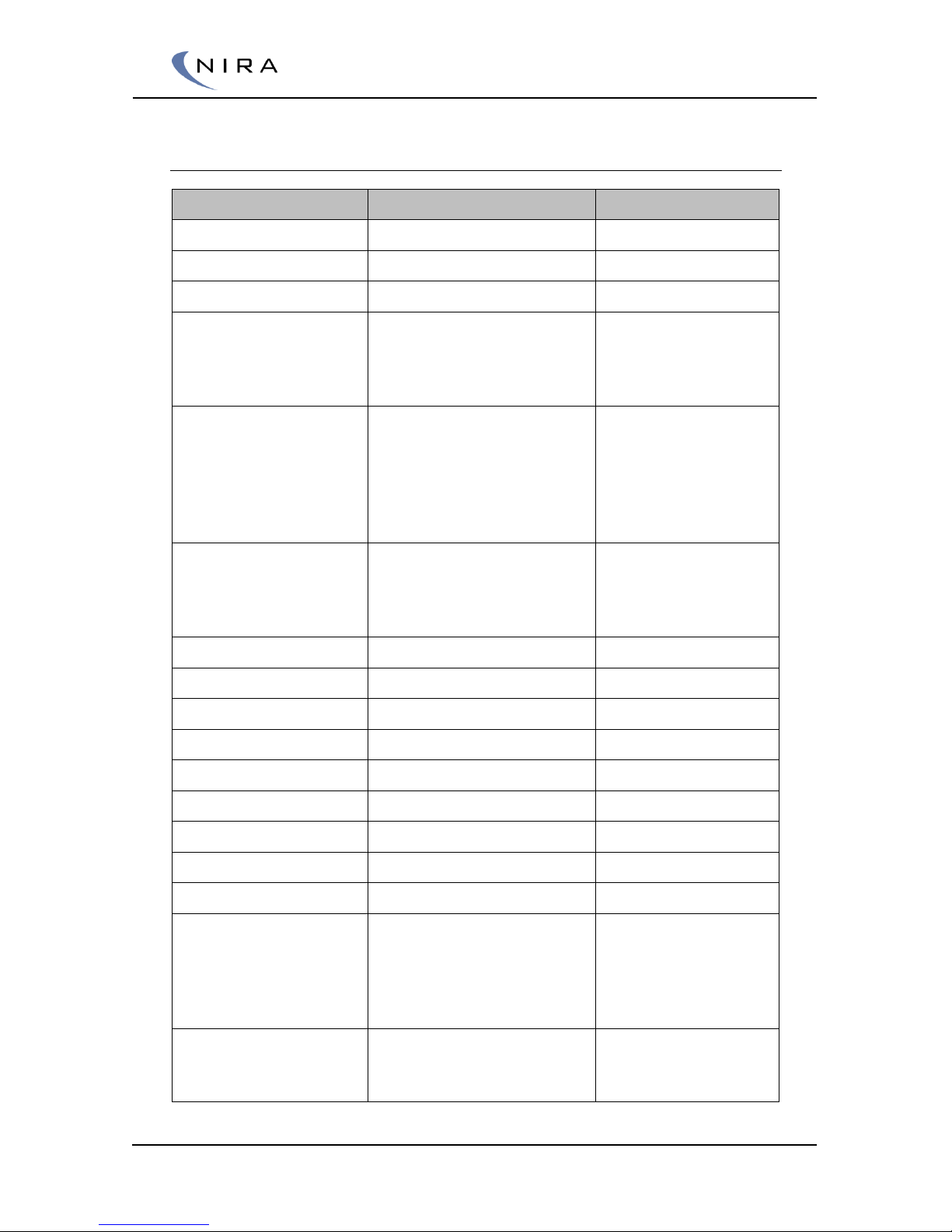
1.2.1 NIRA Rk Naming
Abbreviation
Meaning
Description
Als
Anti Lag System
-
Am
Air Mass
-
App
Accelerator Pedal Position
-
Bac
Boost Actuator Control
This is used if a
boost actuator is
used with position
feedback
Bc
Boost Control
Normally used in
Motorsport if not an
advanced boost
control is used (for
example VGT with
position feedback)
Bv
Base Variable
Variables to show
the user data. For
example Engine
Coolant temperature
Dge
Diagnostic
-
Di
Digital Input
-
Do
Digital Output
-
Es
Engine State
-
Esc
Engine Speed Control
-
Etm
Electronic Throttle Module
-
Fm
Fuel Mass
-
Ign
Ignition
-
Lmc
Lambda Module Control
-
Tpu
Time Process Unit
Processor that read
values from time
critical sensors (for
example crank
sensor)
Vh
Vehicle
Example traction
control variables
(TC).
Page 11
© 2005-2016 Nira Control AB 11
1.3 NIRA i7x Functionality
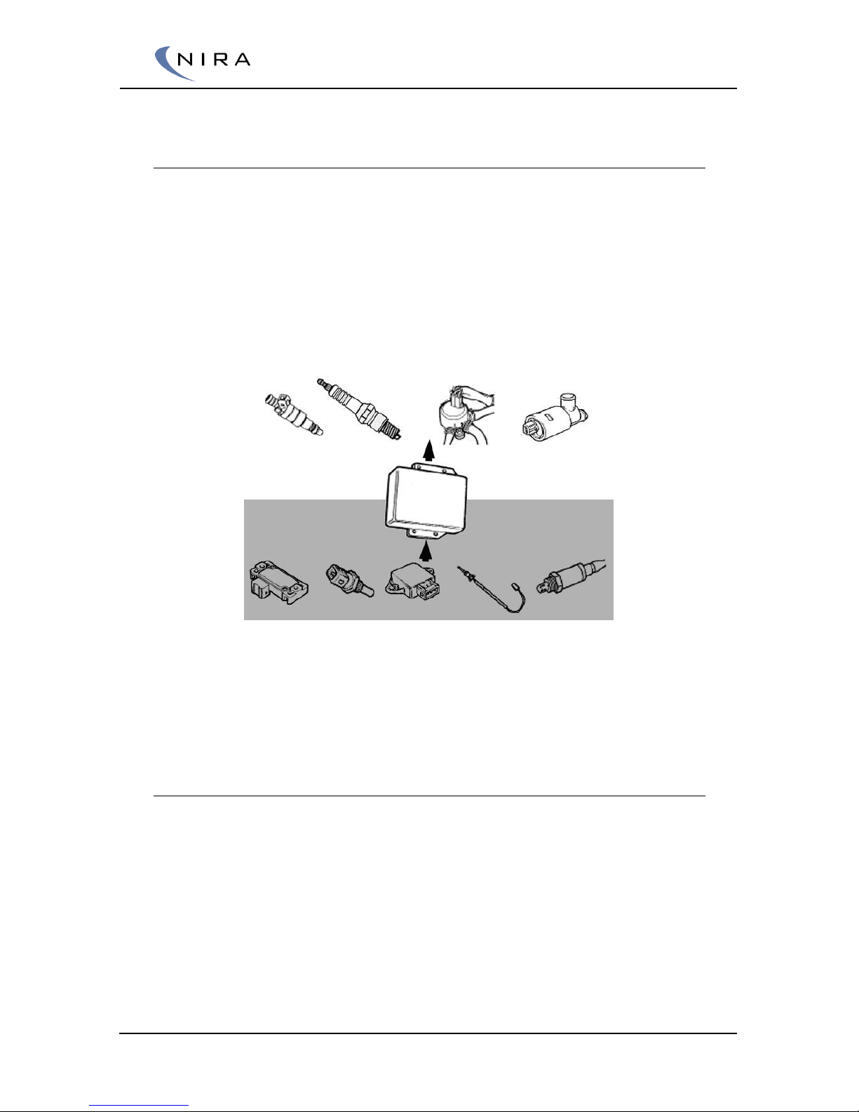
NIRA i7x reads sensor values, processes the data and sends output signals to
various actuators.
NIRA i7x is a fully sequential engine management system for engines with up
to 8 cylinders.
By using the NIRA rk software, you have the ability to modify many of the
parameters that control the data processing and the output signals in NIRA
i7x.
Picture 1-1: Overview of NIRA i7x inputs and outputs.
Picture 1-1 above shows the input signals and the output controls of NIRA
i7x. Section 1.3.1 below lists all sensors used by NIRA i7x. Section 1.3.2 lists
additional input controls used by NIRA i7x and section 1.3.3 lists output
functions.
1.3.1 Sensors
MAP sensor (Manifold Absolute Pressure)
Boost sensor (Pre throttle pressure measurement)
MAT sensor (Manifold Air Temperature)
CKP sensor (Crankshaft Position) Inductive or Hall
TPS (Throttle Position Sensor, measures the throttle butterfly angle)
CMP sensor (Cam Position. The crankshaft rotates two revolutions per
four strokes in a four-stroke engine. The camshaft rotates half as fast as
the crankshaft so it completes one revolution per four strokes. The
Page 12

© 2005-2016 Nira Control AB 12
CMP sensor is used to determine in which of the two crank revolutions
the engine is. This is used during cranking.) Inductive or Hall
ECT (Engine Coolant Temp)
Fuel Temperature (for display purpose)
Fuel Pressure
Oil Pressure
Lambda sensor (NIRA i7x Street controls Bosch LSU 4.9 lambda
sensor without external electronics)
EGTC (Exhaust Gas Temperature. Measures the exhaust gas
temperature in the exhaust manifold where the headers collect. NIRA
i7x handles either digital egtc reading, resistive reading or 0-5V analog
input)
Flat Shift Switch
11 Aux inputs ( 3 Analog inputs, 6 Resistive temp sensors, 2 Digital
inputs)
1.3.2 Input Controls (driver controlled)
Switch for Anti Lag System (ALS, response system)
Button for Launch Control
1.3.3 Output Functions
NIRA i7x processes the input signals and controls the output signals in order
to manage the following actuators.
8 Fuel injectors (amount and sequence)
8 Ignition coils (timing and dwell time). NIRA i7x controls active coils
(with integrated drivers) or passive coils that are connected to NIRA
i7x via an external ignition driver
Boost pressure control valve (controls boost pressure H bridge or
PWM output)
IAC (Idle Air Control; controls engine idle speed via ignition
compensation and an IAC valve or motor)
Fuel pump relay
Main relay (for actuator power supply)
Fan relay (for controlling radiator fan)
Tachometer output (engine speed)
Page 13

© 2005-2016 Nira Control AB 13
ALS solenoid (for additional bypass air)
4 Aux outputs ( Auxiliary relay control and 3 PWM outputs)
Electronic throttle actuator
In addition to standard engine management, NIRA i7x includes a set of
additional engine control strategies and functions. These are listed in section
1.3.4 and are described in detail later in this manual.
1.3.4 Additional Control Strategies/Functions
Launch Control – enables fast take-offs with stable, pre-programmed
torque values
Anti Lag System (ALS) – maintains boost pressure during shifts and
when letting off on the gas
Flat Shift – reduces engine torque to enable quick gear shifts
FlexiPorts™ - a very advanced function that controls fuel injection,
ignition, boost pressure and Launch Control in relation to input axes
configured during calibration
Acceleration Fuel Enrichment –advanced fuel enrichment during
acceleration
Cranking Fuel Enrichment – allows precision control of fuel injection
during cranking based on parameters such as ambient temp, time
since last cranking attempt etc
Alarms – adjustable alarm thresholds reduce the risk of engine
damage
Limp home – any input sensor value out of range is replaced with a
reasonable value to keep the engine running, albeit at reduced power.
Sets error code
Diagnostics – read error codes
Logging – advanced data logging and graphical analysis tools in NIRA
rk software
Page 14
© 2005-2016 Nira Control AB 14
2
Combustion, Lambda and
Measurement Principles
For combustion to take place, oxygen needs to be available. The oxygen
content of the air changes with air temperature and pressure. In an engine
there are different ways of measuring the amount of air entering the engine,
but regardless of the technique used, some way of converting the
measurements into an absolute air mass is needed.
Once the air mass has been calculated, it’s possible to meter the amount of
fuel needed. The optimal air to fuel ratio, as measured in weight, depends on
the type of fuel.
For instance, 1 gram of standard gasoline should be mixed with 14.6 grams
of air to achieve complete combustion. This air/fuel ratio is known as the
stoichiometric ratio and is also referred to as lambda 1.0. A richer mixture
(more fuel) results in lambda < 1.0. A leaner mixture results in lambda > 1.0.
Lambda is central to the calibration of NIRA i7x and it’s important to
understand what it represents and how it’s used.
2.1 Relationship Between A/F and Lambda
A/F means Air-Fuel ratio. It’s always given as a ratio of masses. The
stoichiometric A/F is different for different types of fuel.
Example of stoichiometric A/F ratios:
Air/98 Octane Gasoline = 14.6
Air/Methanol = 6.8
Air/Ethanol = 9.0
Air/E85 = 11
Page 15
© 2005-2016 Nira Control AB 15
Lambda is defined as:
λ = (actual air fuel ratio)/(stoichiometeric ratio)
The definition of lambda is the same regardless of fuel type, which is
advantageous, especially when switching between fuels.
Example of lambda calculation (using gasoline):
If an engine is running lean, the actual A/F may be 15.4:1.
λ = 15.4/14.6 = 1.05
If an engine is running rich, the actual A/F may be 14.0:1.
λ = 14.0/14.6 = 0.96
Some wide-band lambda sensors use A/F in their specs, so it is important to
understand the relationship between A/F and lambda.
2.2 The Effect of Different Lambda Values
If lambda is far from 1.0, the air-fuel mixture can’t be ignited. This causes
engine misfires. The point at which these occur depends on several different
parameters, such as the temperature in the combustion chamber, the
efficiency of the ignition system and how well mixed the air and fuel are.
Typically, lambda has to stay within the 0.7 – 1.2 range.
If the air and fuel haven’t mixed fully before ignition, some amount of fuel will
be wasted. This is common, especially during transients and at low rpm’s.
Consequently, most engines run better when the mixture is a bit richer than
lambda 1.0. A good rule of thumb is 5-7% richer, or lambda 0.95-0.93.
Adding even more fuel usually lowers engine efficiency at a given intake air
pressure but it also cools the combustion chamber. This is exploited in turbo
charged engines where the boost pressure can be increased somewhat while
avoiding premature detonation, or engine knock.
The end result is that by running a turbo engine extra rich, you can gain more
power. On a normally tuned turbo engine, it’s common to adjust lambda
down towards 0.84. On an aggressively tuned engine, lambda may have to
go even lower if there are problems with the exhaust gas temperature being
too high.
Page 16
© 2005-2016 Nira Control AB 16
2.3 Measurement Principles
All engine management systems have to determine engine position and
calculate the correct mass of fuel to inject for a given mass of air. The masses
of the fuel and air vary with temperature and pressure.
2.3.1 Angular positioning
The engine angular position of the crank shaft is crucial for accurate engine
control.
The most common types of sensors used for angular positioning in
automotive applications are
Hall sensor
Inductive sensor
Hall sensor
The Hall Effect is based on a magnetic field that affects electrons moving in a
conductor. The sensor is in need of power supply and the output is a square
wave with fixed voltage levels. The output level is equal or less the supply
voltage.
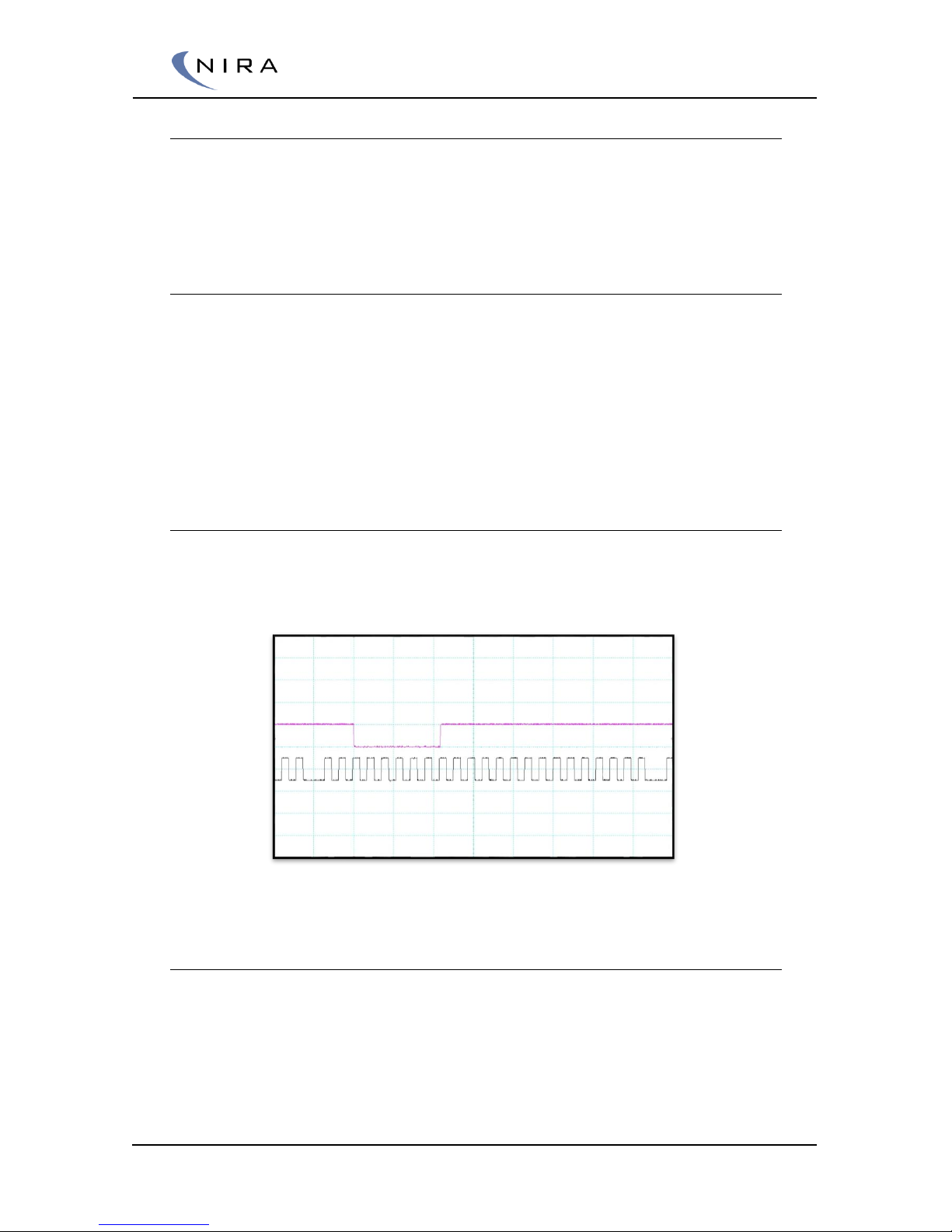
Example of CKP & CMP hall sensors plotted over one revolution. “CKP is a 24-1 pattern”
Inductive sensor
The inductive sensor or VR sensor (Variable Reluctance) uses the
phenomenon of induced voltage in the sensor. The voltage is induced when
ferrite steel passes the sensor and changes the flux through the sensor’s built
in magnet. Therefore the sensor is not in need of any power supply. The
output voltage from the sensor will go from negative to positive values. The
output levels from the sensor will increase proportionally to the speed of the
tooth passing the sensor.
Page 17
© 2005-2016 Nira Control AB 17
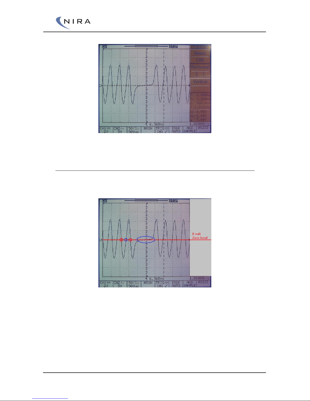
Example of an inductive CKP sensor signal when a ”2 lost” is detected from a pulse wheel
with a ”60 – 2 lost” pattern
Zero crossing detection and crank polarity
When using an inductive sensor the system uses zero crossing detection to
determine the position of the crankshaft.
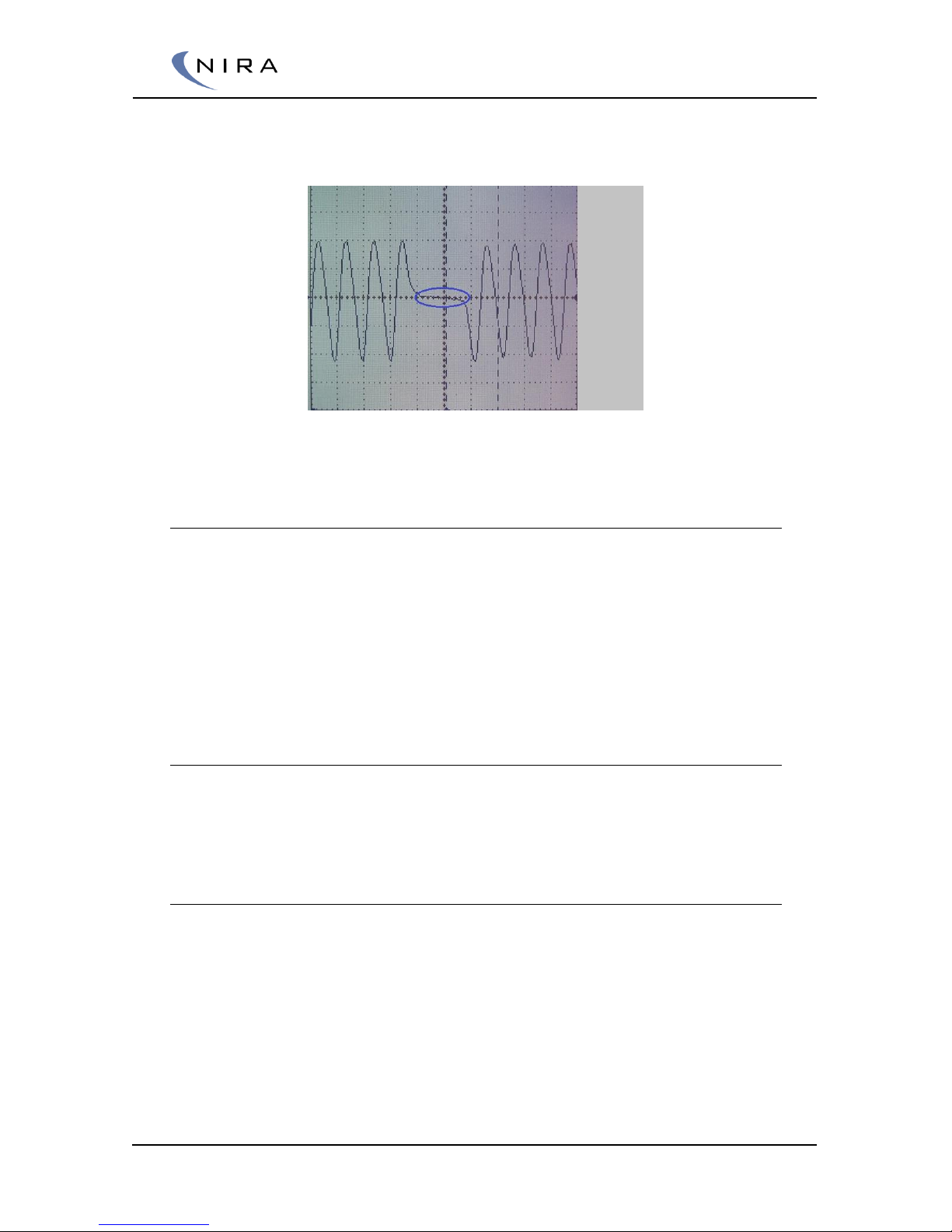
Examlpe of zero crossing detection for falling & rising edge.
The picture above shows two types of zero crossing.
The red circle shows zero crossing at the transition from high level to
low level, falling edge
The blue circle shows zero crossing at the transition from low level to
high level, rising edge. In the “lost gap” the zero crossing is widely
spread and can’t be uniquely defined
By swapping the polarity of the inductive sensor the signal will be inverted.
NIRA i7x uses zero crossing detection at falling edge, which means the scope
Page 18
© 2005-2016 Nira Control AB 18
picture has to look like the pictures above. The level transition through the “2
lost”-gap cannot be falling in this case.
Example of wrong polarity at inductive sensor. The level transition through the gap is falling
and the zero crossing will be undefined in the blue circled area.
2.3.2 Volumetric Efficiency (VE)
For controlling the air mass flow through the engine, a volumetric efficiency
model can be used. The VE model uses Manifold Air Pressure or Throttle
Position sensor together with Engine Speed to choose a VE value. The VE
value is volumetric fill rate of the displacement and calculated for every
stroke. A VE value of 1 means that 100 % of the cylinder is filled with air
during intake stroke. For example, if the cylinder volume is 500 cc, the
engine breathes in exactly 500 cc of air while the intake valve is open.
VE to Fuel Mass
With the density of air, the volume can be converted to air mass filled into
the cylinder every stroke. Based on the air mass filled into the cylinder it is
possible to calculate fuel mass based on the desired A/F-ratio.
Volumetric Efficiency and Boost Pressure
The Volumetric Efficiency does not have to increase with increased boost
pressure. The intake air mass will increase and thus, the volume filled into the
cylinder contains compressed air. If high exhaust manifold pressure occurs,
the VE might even decrease.
Page 19

© 2005-2016 Nira Control AB 19
2.3.3 Mass Airflow Sensors (MAF)
Most modern engines have MAF sensors. These essentially weigh the
incoming air before it enters the engine. The engine control system receives
information about how many grams of air/millisecond have passed through
the MAF sensor.
Using a MAF has a major advantage in that it reports only the amount of air
that actually enters the engine. Engine wear during a long life is factored in
automatically using this approach. Additionally, MAF sensors simplify the fuel
calibration significantly. This was especially important many years ago when
the computational power of the microprocessor in the engine management
system was limited.
Today, MAF is the standard because of strict emission standards that apply
during the entire life of the engine. There are, however, several
disadvantages:
MAF sensors are slow to react, expensive and sensitive to damage.
There are often problems using MAF sensors on aggressively tuned
engines because the sensor can break due to high airflow
The sensor itself is mounted in a housing, which represents a
restriction to the intake air
There are also problems with oil entering the intake tract from the
turbo due to the restriction
2.3.4 Alfa-N and Speed-Density
During the mid-1990’s many cars used speed-density systems. Speed-density
systems have no restrictions in the intake tract (as compared to MAF sensor
systems) and the precision was good enough over the lifetime of the engine
to meet the emission rules of the time.
On low cost vehicles, Alfa-N systems were common. Alfa-N systems are very
inexpensive to manufacture because they only require a high-precision TPS.
Unfortunately, as the engine wears, the TPS value no longer is a correct
measure of how much air the engine takes in and this leads to emissions
related problems
NIRA i7x has the capability to control fuel injection (and ignition) based on
speed-density, Alfa-N -- or a combination of the two.
2.4 Fuel delivery
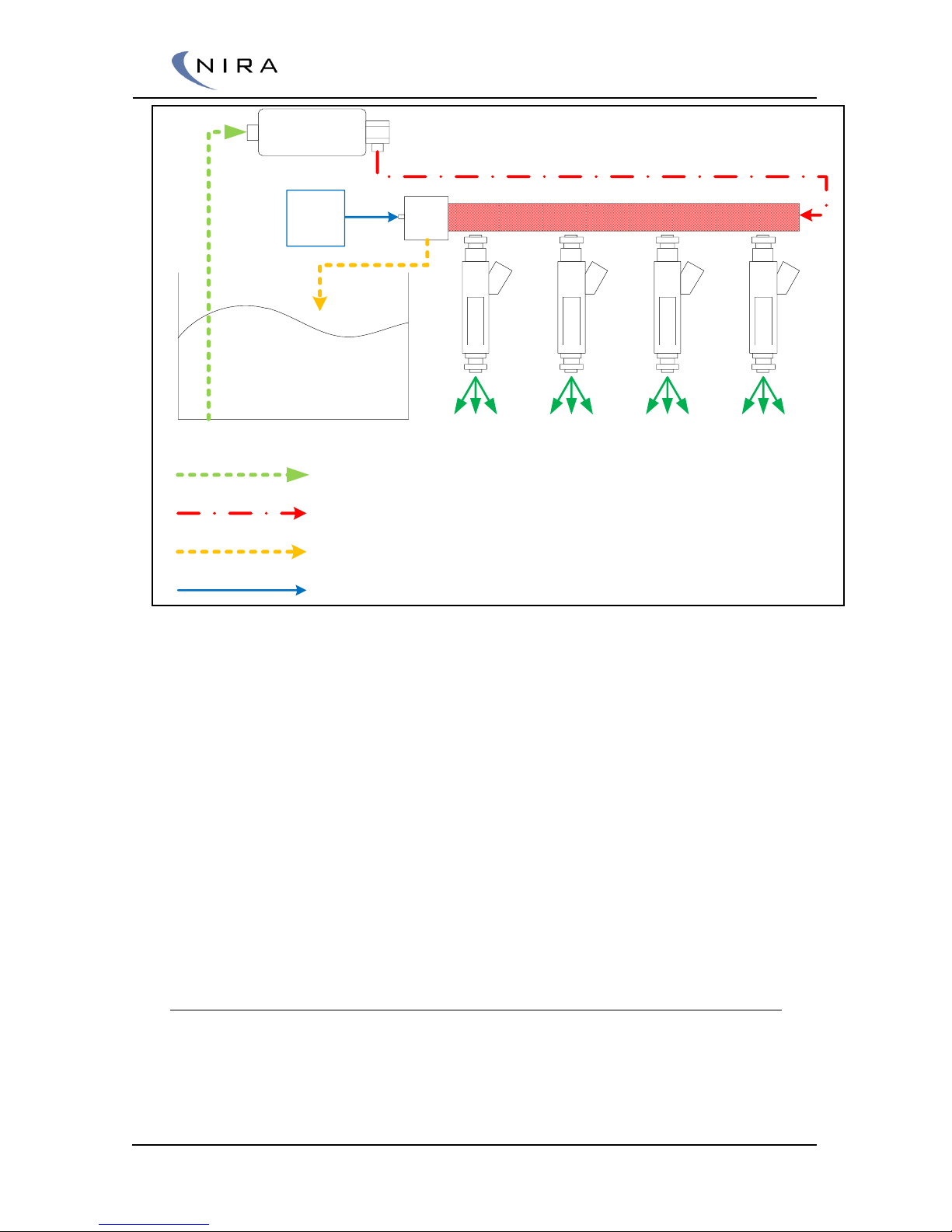
See the example picture below over a fuel delivery system.
Page 20
© 2005-2016 Nira Control AB 20
Fuel Rail
Fuel Pump
FPR
Fuel Tank
Manifold
Air
Pressure
Low fuel pressure
High fuel pressure
Low fuel pressure. Back flow
Manifold Air Pressure
Overview of fuel delivery system
Fuel Pump: The purpose is to pump fuel from the tank or catch tank
and pressurize the fuel rail
Fuel Rail: The hardware connection that feed the injectors with
pressurized fuel
FPR (Fuel Pressure Regulator): FPR controls the fuel pressure by
controlling backflow. The FPR is often adjustable to set the base
pressure.
A hose from the manifold is connected to the FPR with purpose to
increase or decrease the fuel pressure when manifold air pressure
changes. The most common is to increase the pressure in a linear
relationship
Injector: Injectors supply the engine with fuel by injecting fuel in the
inlet port. The injectors are electrically controlled by NIRA i7x.
2.4.1 Why use a Fuel Pressure Regulator with MAP Feedback
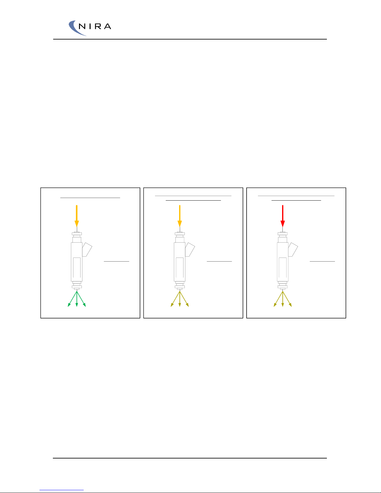
As described above, the fuel pressure is increased with raised manifold air
pressure. The reason for this is to keep the same pressure balance over the
injector.
Page 21
© 2005-2016 Nira Control AB 21
When testing an injector fuel flow rate in a test rig, the fuel pressure is fixed
(~3bar = 400 kPa absolute) and the injectors injects into atmospheric
pressure (~100 kPa absolute). That means that the pressure balance over the
injector is 400-100 = 300 kPa. The injector flow rate for these conditions is
entered in to ECU for fuel mass calculation.
Injectors mounted at an engine will inject the fuel into the air pressure of the
manifold. If a fixed fuel pressure is used, the pressure balance over the
injector will vary with manifold air pressure. This causes the ECU miscalculate
the fuel mass to be injected.
By using a linear fuel pressure regulator with MAP feedback, the fuel pressure
will increase 1 bar if the manifold air pressure increases 1 bar. This way, the
pressure balance over the injector will remain the same.
If a nonlinear fuel pressure regulator is used, a compensation has to be
entered into the ECU to make the fuel calculations correct.
P1 = 3 bar (4 bar abs)
P2 = 0 bar (~1 bar abs)
ΔP= 3 – 0 = 3 bar
P1 = 3 bar (4 bar abs)
P2 = 1 bar (~2 bar abs)
ΔP= 3 – 1 = 2 bar
Test conditions for characterization
Running conditions 1 bar boost pressure (P2)
Without Fuel Pressure Regulator
P1 = 4 bar (5 bar abs)
P2 = 1 bar (~2 bar abs)
ΔP= 4 – 1 = 3 bar
Running conditions 1 bar boost pressure (P2)
With Fuel Pressure Regulator
Picture of injector pressure balance variation due to manifold air pressure and fuel pressure
Page 22
© 2005-2016 Nira Control AB 22
3
Installing NIRA i7x
When installing NIRA i7x it is recommended that you follow the directions
below. Begin by determining if additional sensors are needed and where to
install them. Make sure any existing sensors you expect to use with NIRA i7x
are in good working order. The NIRA i7x wiring harness has markings in clear
text on each wire to simplify the work of connecting all the sensors.
Each sensor and actuator will need an appropriate connector attached to the
harness. The connector terminals should be crimped for best performance
and rubber seals should be used where the wires enter the connector
housing. (Your NIRA i7x dealer sells seals for all sensors.) If proper crimp tools
are not available, soldering may be used. Poorly crimped terminals are a
common source of intermittent problems. Always cover any soldered splices
with heat shrinkable tubing.
Do not skimp on the sensors. Use new sensors if you are unsure of the
condition of the existing ones. Old throttle position sensors often have hardto-find drop out points which can not be detected with standard multimeters.
Your NIRA i7x dealer stocks many of the sensors needed or can recommend
sensors.
Note that the MAP, MAT and ECT sensors sold by your NIRA i7x dealer have
been pre-calibrated in NIRA rk. These are recommended. Other sensors will
need to be calibrated separately. Calibration is done using one of the
Wizards in NIRA rk.
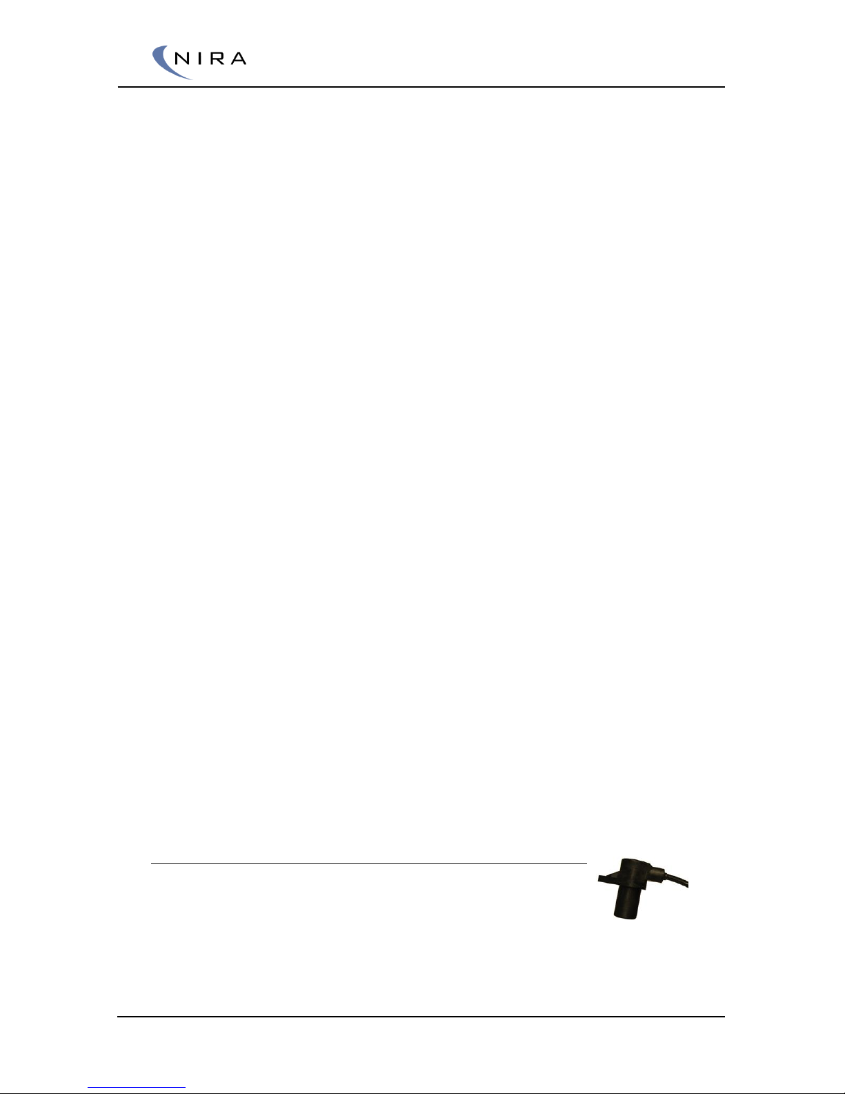
3.1 Crank Position Sensor (CKP) and Trigger
Wheel
To control ignition timing, injection timing and several other
important outputs, NIRA i7x needs a signal that is telling the
position of the crankshaft. This signal is provided by a crank
position sensor that creates the signal by reading the pattern of a pulse
wheel that is fitted to the crankshaft. NIRA i7x supports both hall sensors and
inductive sensors.
Page 23
© 2005-2016 Nira Control AB 23
In the wiring harness there’s a shielded wire marked “Crank” with to wires
and one shield. The same wire should be used for both hall sensors and
inductive sensors. Note the different sensor types are differently connected
in the NIRA i7x connector.
Connection of Crank sensor
Type
Sensor Pin
Nira i7x pin
Wire
Hall
sensor
5v Supply
E.95
Wire 1
Signal
E.72
Wire 2
Ground
E.92
Shield
Inductive
Signal +
E.93
Wire 1
Signal -
E.94
Wire 2
Shields
N.92
Shield
An accurate signal from the crank position sensor is crucial. Therefore, it is
very important to install the CKP sensor with diligence. A faulty installation or
a bad combination of CKP sensor and pulse wheel causes an unreliable
signal. In turn, an unreliable signal will make the engine run poorly.
It’s important that the sensor mounting bracket is solid and that the trig
wheel is 100 % aligned with the crankshaft.
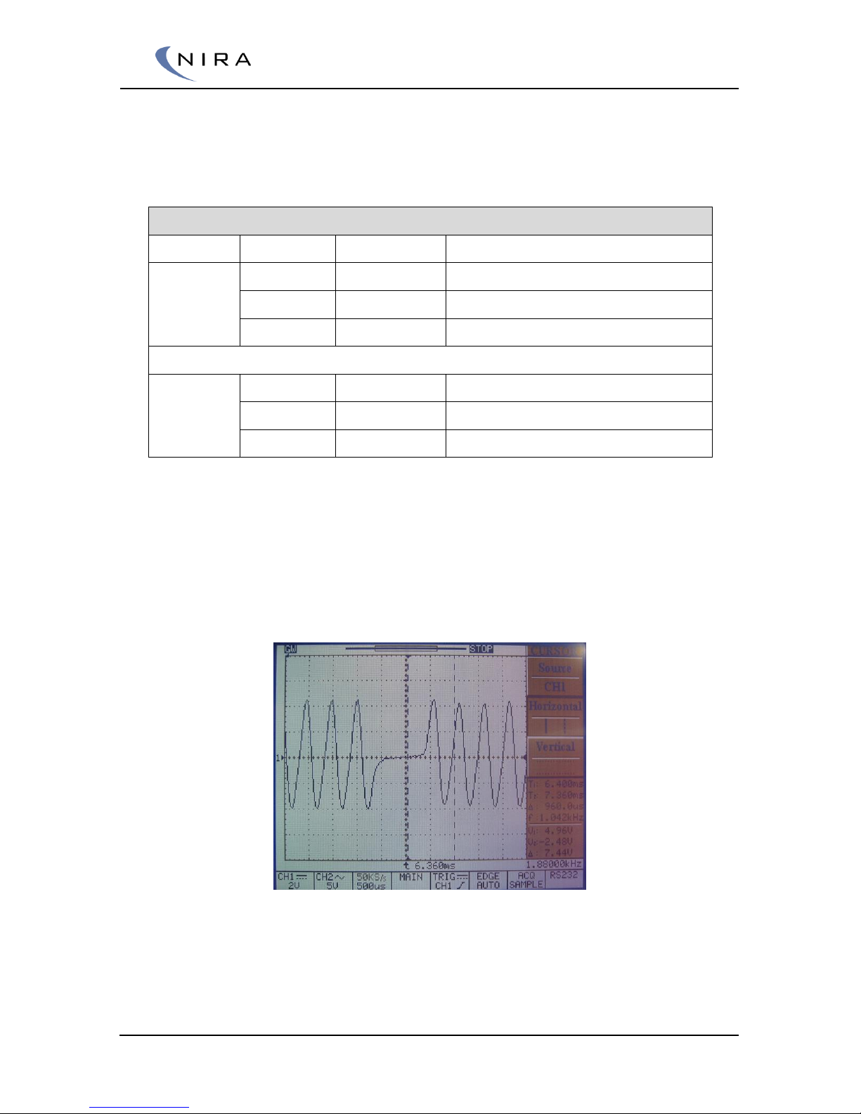
Example of an inductive CKP sensor signal when a ”2 lost” is detected from a pulse wheel
with a ”60 – 2 lost” pattern.
The signal from the CKP sensor should resemble the pattern in the image
above. It is recommended to use an oscilloscope to study the signal.
Page 24
© 2005-2016 Nira Control AB 24
Definition of a Trig and Maximum Voltage
Trig
Occurs when a falling pulse flank passes zero
Min voltage
0,4 V between peak and ground at 100 rpm. 2,5
V at 6 000 rpm
Max voltage
300 V peak to peak
3.1.1 The Pulse Wheel
NIRA i7x works with the majority of standard pulse wheels
that has one or two pulses “removed” as a reference point. On engines
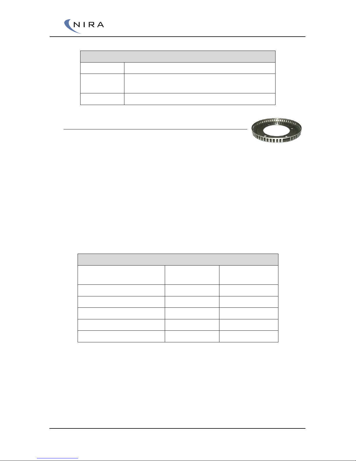
where such a pulse wheel is factory fitted it is recommended to keep the
factory installation. The picture above and right is showing a pulse wheel of
the type “60 – 2 lost” that is a standard pulse pattern. This pulse wheel has
58 teeth and a gap that is created by the removal of 2 teeth in the otherwise
symmetrical pattern. Hence the name “60 – 2 lost”. NIRA i7x is designed to
handle pulse wheels of the types “60 – 2 lost”, “60 – 1 lost”, “ and
symmetrical pulse wheels down to “16 – 2 lost” and “16 – 1 lost”.
Symmetrical pulse wheels have teeth that are equally distributed around the
pulse wheel with the exception of a reference point where one or two teeth
are missing. The table below describes the pulse wheels that are compatible
with NIRA i7x.
Pulse Wheels Compatible with NIRA i7x
No of teeth, including
”missing teeth”
Pattern no 1 (1
tooth removed)
Pattern no 2 (2
teeth removed)
60 (each tooth + gap is 6°)
60 – 1 lost
60 – 2 lost
59
59 – 1 lost
59 – 2 lost
… … …
17
17 – 1 lost
17 – 2 lost
16
16 – 1 lost
16 – 2 lost
NIRA i7x reads symmetrical pulse wheels that are split into a maximum of 60 sections (60 – 1
lost, 60 – 2 lost) and a minimum of 16 sections (16 – 1 lost, 16 – 2 lost). All symmetrical
patterns in between are compatible with NIRA i7x.
As shown in the table above, NIRA i7x handles the most common types of
factory fitted pulse wheels, such as “60 – 2 lost” found on European cars
(Volvo, Saab, Audi, BMW, Mercedes, etc), Ford’s “36 – 1 lost” and “24 – 1
lost” found on many motorcycle engines. There must not be any doubts
regarding what type of pulse wheel that is fitted on the engine. The pattern
Page 25
© 2005-2016 Nira Control AB 25
must be entered into NIRA rk and it is absolutely necessary to enter the
correct values to be able to start the engine.
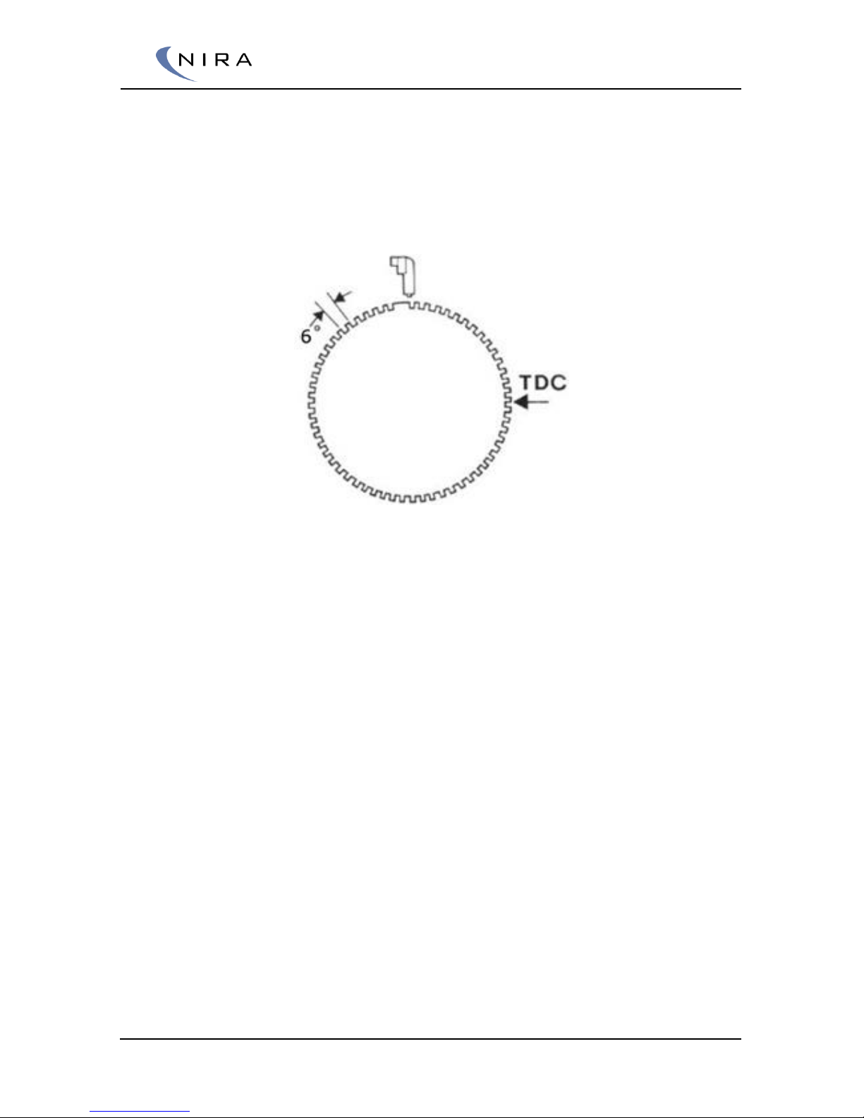
Some types of pulse wheels are made with holes drilled in a solid material.
These pulse wheels often have a reference point in the shape of a peak
instead of a valley – see the image below for sketch of a “60 – 1 lost” hole
with a peak as a reference point.
Pulse wheel with a ”60 – 1 lost” pattern and a peak instead of a valley as reference point.
Pulse wheels having a peak instead of a valley or a hole as a reference point
are more error prone since vibrations can cause false trigs when the reference
point passes the sensor. If you are fitting a new pulse wheel when installing
NIRA i7x, always choose a pulse wheel with a valley as reference point.
The trigger wheel mounts on the face of the crank pulley. If the crank pulley
is also a harmonic balancer, verify that it is in good condition and isn’t
slipping. Make sure the trig wheel is aligned on the pulley. If it is not
centered properly, the signal strength from the CKP sensor will vary and
ignition timing will drift back and forth.
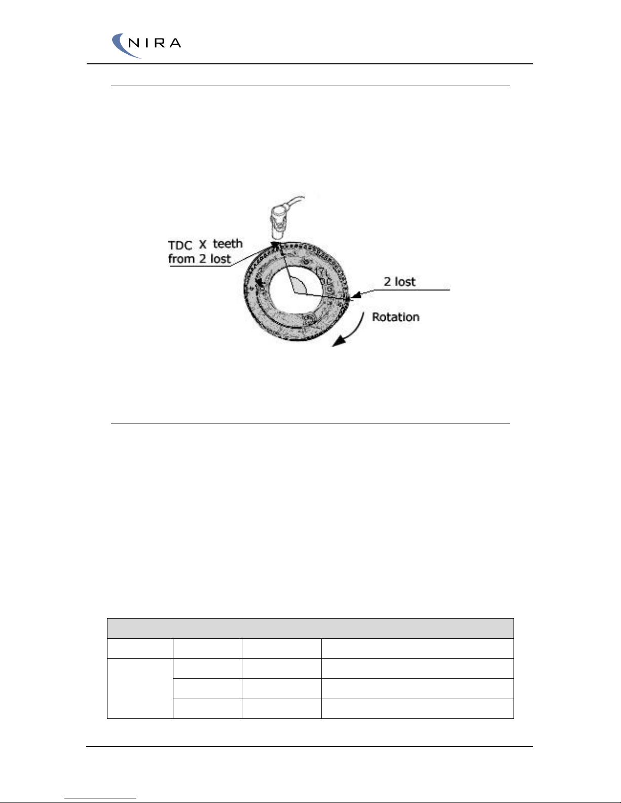
The example below is given for fitting a “60 – 2 lost” pulse wheel: When
figuring out the angular placement of the trigger wheel, first turn the engine
to TDC for cylinder 1. Then place the trigger wheel such that the angle
between the “2-lost” window and the place where you plan on mounting the
CKP sensor is around 90-120 degrees. See picture 3-1 below. You will later
need to measure the exact angle, see section 3.1.2.
Once the trigger wheel has been fitted, mount the CKP sensor. The gap
between the CKP sensor and the trigger wheel should be 0.5-1.0mm. If the
gap is greater than 1.0 mm, the signal strength from the CKP sensor will vary
too much and timing will drift back and forth. Mount the sensor in a bracket
that allows for slight adjustments. Secure the CKP sensor wires with cable ties
to make sure they don’t interfere with e.g. engine drive belts.
Page 26
© 2005-2016 Nira Control AB 26
3.1.2 Measuring the ”2-lost” Angle
Turn the engine so that cylinder 1 is at TDC. Measure the angle between the
center of the CKP and the trailing edge of the 2-lost (or 1 lost) window. See
picture 3-1. Each tooth on the trigger wheel is 3 degrees and each window is
3 degrees. Make a note of the angle, as you will need to enter it into NIRA rk
later.
Picture 3-1. Measuring the TDC to ”2-lost” angle.
3.2 Cam Position Sensor (CMP)
Since the fuel injection and ignition is controlled sequentially with NIRA i7x, a
signal that tells NIRA i7x the engine’s phase in the combustion cycle is
necessary. NIRA i7x thus requires that the engine has a Cam Position Sensor.
This signal is used to synchronize the fuel injection and ignition with opening
and closing of the intake valves during start. Your NIRA i7x dealer will advise
you on an appropriate CMP sensor. Both hall sensors and inductive sensors
are compatible with NIRA i7x.
In the wiring harness there’s a shielded wire marked “CAM” with two wires
and one shield. The same wire should be used for both hall sensor and
inductive sensor. Note that different sensor types connect differently in the
NIRA i7x connector.
Connection of CAM sensor
Type
Sensor Pin
Nira i7x pin
Wire
Hall
sensor
5v Supply
E.74
Wire 1
Signal
E.73
Wire 2
Ground
E.71
Shield
Page 27
© 2005-2016 Nira Control AB 27
Inductive
Signal +
E.73
Wire 1
Signal -
E.71
Wire 2
Shields
TBD
Shield
In order to create a well-defined trig point for the CMP sensor, drill and tap a
hole in the cam gear. Insert a screw into the hole such that the screw head
faces the sensor. The sensor works best if the screw material is magnetic,
such as galvanized steel. The distance between the screw and the sensor may
need to be adjusted in order for the sensor output voltage to be high
enough. The output voltage from the CMP sensor needs to be at least 3V.
Do not place the trig point in a place that gives a CMP signal at the same
time that the reference point of the crankshaft pulse wheel passes the CKP
sensor.
Sometimes it’s possible to use one of the camshaft lobes as a trigger.
3.3 Throttle Position Sensor (TPS)
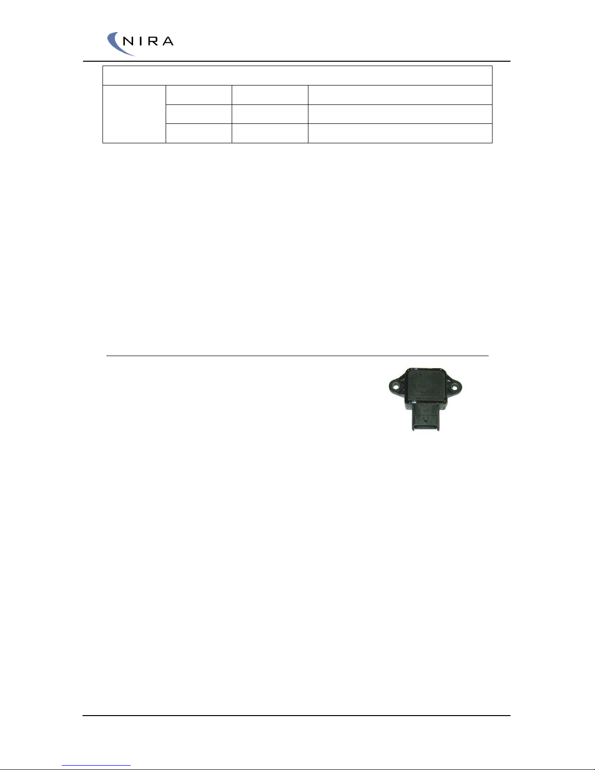
The TPS needs to be of a linear potentiometer type. A
worn TPS can cause problems which are very difficult
to diagnose. Typically, as the TPS ages, the signal
drops out intermittently. Either verify that your existing
TPS is in excellent working order or simply replace it
with a new one. Your NIRA i7x dealer stocks a suitable
TPS.
If your car doesn’t have a TPS currently, you will need to add one. Some
older cars only came with TP switches for idle and WOT. These can not be
used with NIRA i7x.
If you are planning to use Alfa-N calibration at low loads and expect to be
able to adjust the calibration with good precision, you will need a TPS with
excellent temperature stability and very high angular resolution.
When mounting the TPS make sure that it doesn’t bottom out before the
WOT or idle stops. Verify this by observing the TPS while a helper depresses
the accelerator fully and then lets the pedal go completely. At both end
points there needs to be additional travel available for the TPS. If not, adjust
the position of the TPS relative to the throttle shaft.
The TPS mounts on different sides of the throttle housing on different cars.
This will cause the TPS to turn in different directions on different cars as the
throttle opening increases. If the TPS signal on your car is reversed, simply
swap the Throttle Sensor Ground and Throttle Sensor Supply wires.
Page 28
© 2005-2016 Nira Control AB 28
3.4 Manifold Absolute Pressure (MAP) and
Intake Air Temp (MAT)
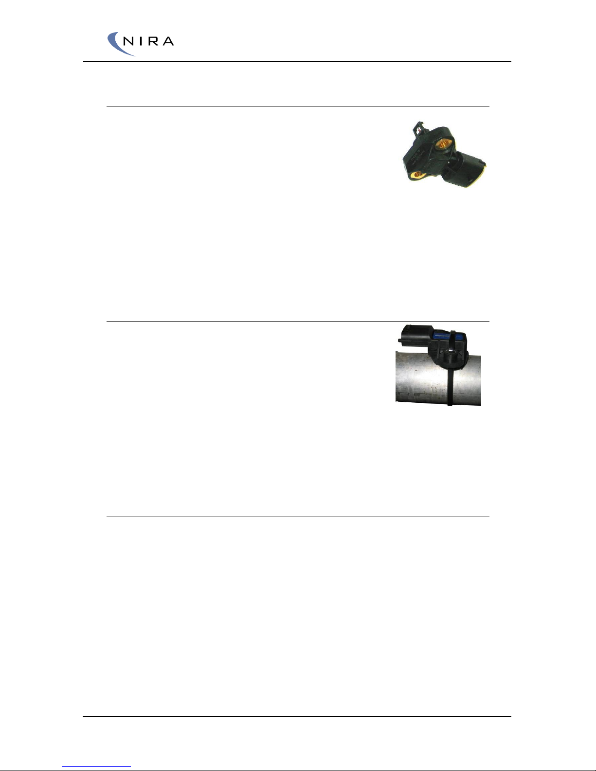
When NIRA i7x is set up as a speed density system,
precise knowledge of both the absolute pressure and the
air temperature in the intake manifold are required in
order to calculate the correct amount of fuel to inject.
If your vehicle already has MAP and MAT sensors you
may be able to use those. The MAT sensor will need to react very quickly to
sudden changes in temperature. This is especially important on a turbo
charged engine where the intake air temp can increase 100 degrees Celsius
within a few seconds.
Your NIRA i7x dealer sells an appropriate combined MAP-MAT sensor. This
sensor is pre-calibrated in the NIRA rk software.
3.4.1 Mounting the MAP/MAT Sensor
The NIRA i7x MAP/MAT sensor mounts on a horizontal
surface on top of the intake manifold after the throttle
butterfly. (For manifolds with multiple butterflies, see
3.4.2 below.) Drill a 12 mm hole and mount the sensor
with the sensing element pointing down in order to
avoid accumulation of droplets on the sensing
element. When you drill the hole, make sure to
vacuum up all shavings. Any shavings left inside
the manifold can cause significant damage to
the engine.
3.4.2 Multiple Throttle Butterflies
If each intake runner has an individual throttle butterfly you can still use a
single MAP/MAT sensor provided you build a small, external plenum and
attach the MAP/MAT sensor to it. The plenum volume should be around 200
ml. Connect the plenum to each individual intake runner, after the throttle
butterfly, using hoses with restrictions. Make sure the restrictions are all the
same size.
With this setup you can still use speed-density mapping, which offers greater
accuracy and stability than using only the throttle angle (Alfa-N mapping),
despite MAP fluctuating at low rpm’s. Calibration is done by changing the
inner diameter of the restrictions. Measure the MAP signal at NIRA i7x with
an oscilloscope. The MAP signal is between pins E.12 and and E.53 of the
Picture 3-4: MAP/MAT
sensor may be secured using
a cable tie if the wall
thickness is too thin.
Page 29

© 2005-2016 Nira Control AB 29
Engine connector at NIRA i7x. When the engine is idling, the voltage is
allowed to vary as much as +/- 15%.
If the voltage swings are greater you will need to decrease the restrictions.
The decrease should result in lesser swings. Avoid using too small restrictions
as this will slows the response time down.
There’s a configurable filter on the MAP input of NIRA i7x. The filter can be
configured using the Advanced setting in NIRA rk. If the pressure variations
are still too large because of significant cam intake and exhaust overlap
(using very aggressive camshafts) NIRA i7x can be set up for Alpha-N
calibration up to a certain MAP (e.g. 70 kPa) and then switch over to speed
density mapping. This is described in detail in a section 5.1.1 below. Being
able to switch between mapping modes like this makes NIRA i7x ideal for use
with highly tuned engines.
3.5 Boost pressure sensor (pre throttle
pressure sensor)
Controlling boost pressure is essential on a turbo charged engine. A great
pressure drop will occur over the throttle body at small throttle angles which
causes even higher pressure before throttle. The high pressure before the
throttle can damage both turbo charger and the piping. To avoid this, NIRA
i7x can be configured to control the boost pressure against the pre throttle
mounted boost pressure sensor.
Mount the sensor in the piping between the charge air cooler and the
throttle body.
3.6 Engine Coolant Temperature
Sensor (ECT)
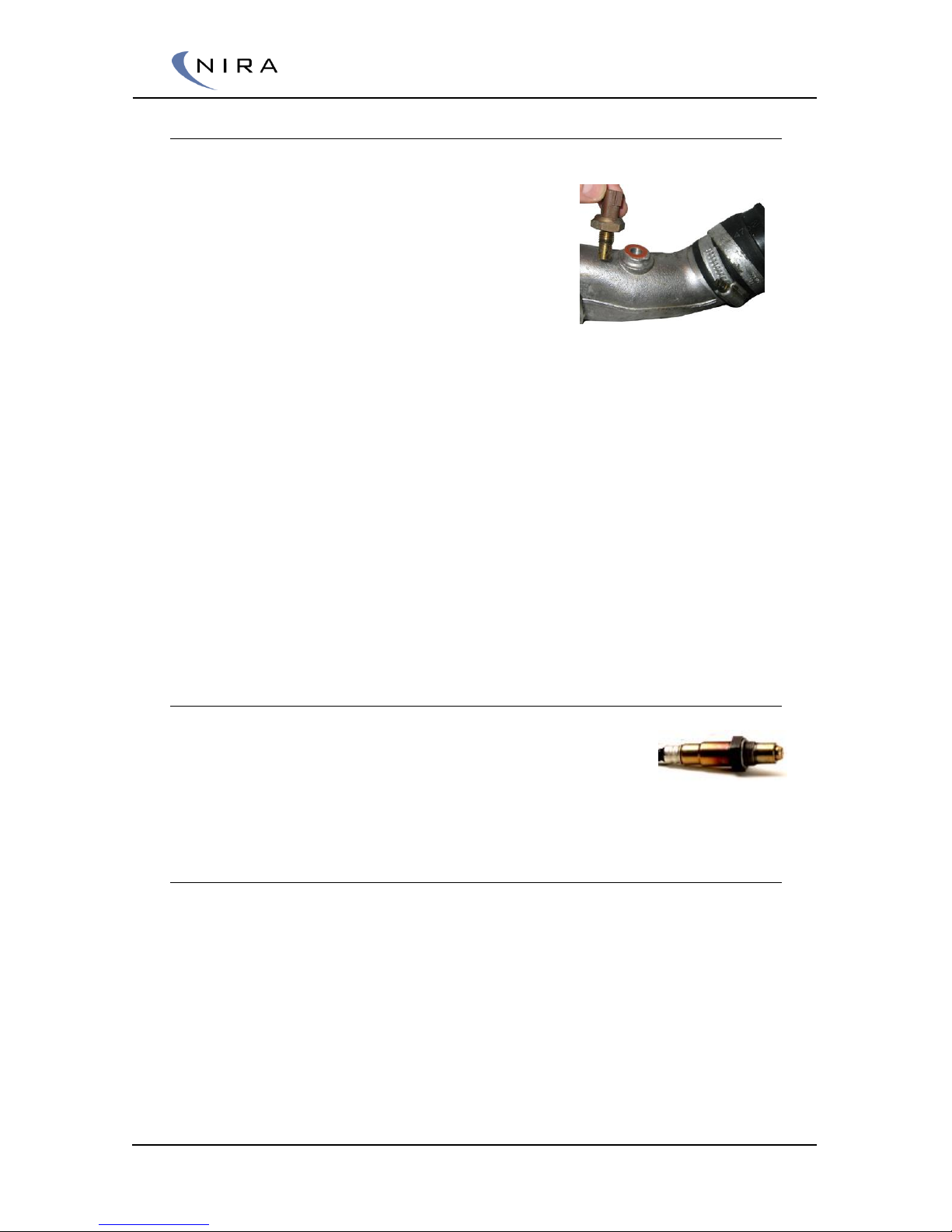
The ECT sensor is used by NIRA i7x to monitor overall engine temperature
and for cold start enrichment. If you plan on using the ECT sensor that came
with your engine you will need to know or establish its resistance as a
function of temperature. This information is often available in the service
manual for your car. Your NIRA i7x dealer sells an ECT sensor which has been
pre-calibrated in the rk software.
Page 30
© 2005-2016 Nira Control AB 30
3.7 Manifold Air Temperature Sensor (MAT)
The MAT sensor is used for air density compensation at different intake air
temperatures. Its function is very important on a
turbo charged engine where the intake air temp
can rise 100 degrees Celsius in mere seconds.
The MAT sensor needs to react quickly and must
be properly calibrated. Your NIRA i7x dealer can
recommend several combined MAP/MAT sensors
that meet these requirements and have been precalibrated in the NIRA rk software.
If you prefer to use the original MAT sensor on your engine you need to
know or establish its transfer function. (The transfer function describes the
resistance of the sensor as a function of the temperature.)
Sometimes the existing MAT sensor is mounted before the throttle butterfly.
In such situations it is recommended to move it after the butterfly, or better
yet, use a combined MAP/MAT sensor mounted after the throttle plate, see
section 3.4
For fast MAT response, use a sensor with a small sensor tip. This is very
important on turbocharged engines where manifold temperature can rapidly
increase. Even more important if you prefer to use MAT compensated
ignition angle.
3.8 Lambda Sensor
It’s very important to have an accurate lambda reading
when calibrating your engine. NIRA i7x controls a Bosch LSU
4.9 oxygen sensor. The sensor is of pump current type and
NIRA i7x will not need any external amplifiers or electronics to control it.
3.8.1 Lambda Sensor Mounting
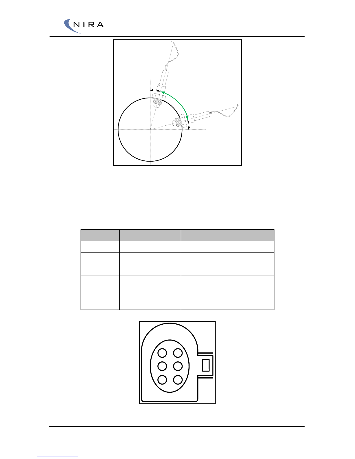
To avoid that condensed liquids are collected in the sensor, a horizontal
inclination of 10 degrees is needed. Due to the temperature limits, mount
the sensor after the turbine with at least 10 degrees vertical inclination.
Maximum exhaust gas temperature for the LSU 4.9 is 930 ºC.
Maximum temperature for the hexagon of the LSU 4.9 is 600 ºC
Page 31
© 2005-2016 Nira Control AB 31
10 degrees
10 degrees
Accepted
mounting
angles
Correct mounting of LSU 4.9 sensor
Your NIRA i7x dealer supplies LSU 4.9 sensor kits. A harness with pre
crimped NIRA i7x terminals is included.
3.8.2 Lambda Sensor Connections
LSU 4.9 Pin
Nira i7x Pin
Description
Pin 1
V.82 LS1 IP / APE
Pump current
Pin 2
V.66 LS1 VM / IPN
Ground Pump current
Pin 3
V.40 LS1 U- / H-
Lambda Heater PWM
Pin 4
V.75 LS1 U+ / H
Lambda Heater Supply
Pin 5
V.65 LS1 IA / RT
Individual trim
Pin 6
V.83 LS1 UN / RE
Nernest voltage
5 6
3 4
1 2
LSU 4.9 Connector, rear view.
Page 32
© 2005-2016 Nira Control AB 32
3.9 Exhaust Gas Temperature.
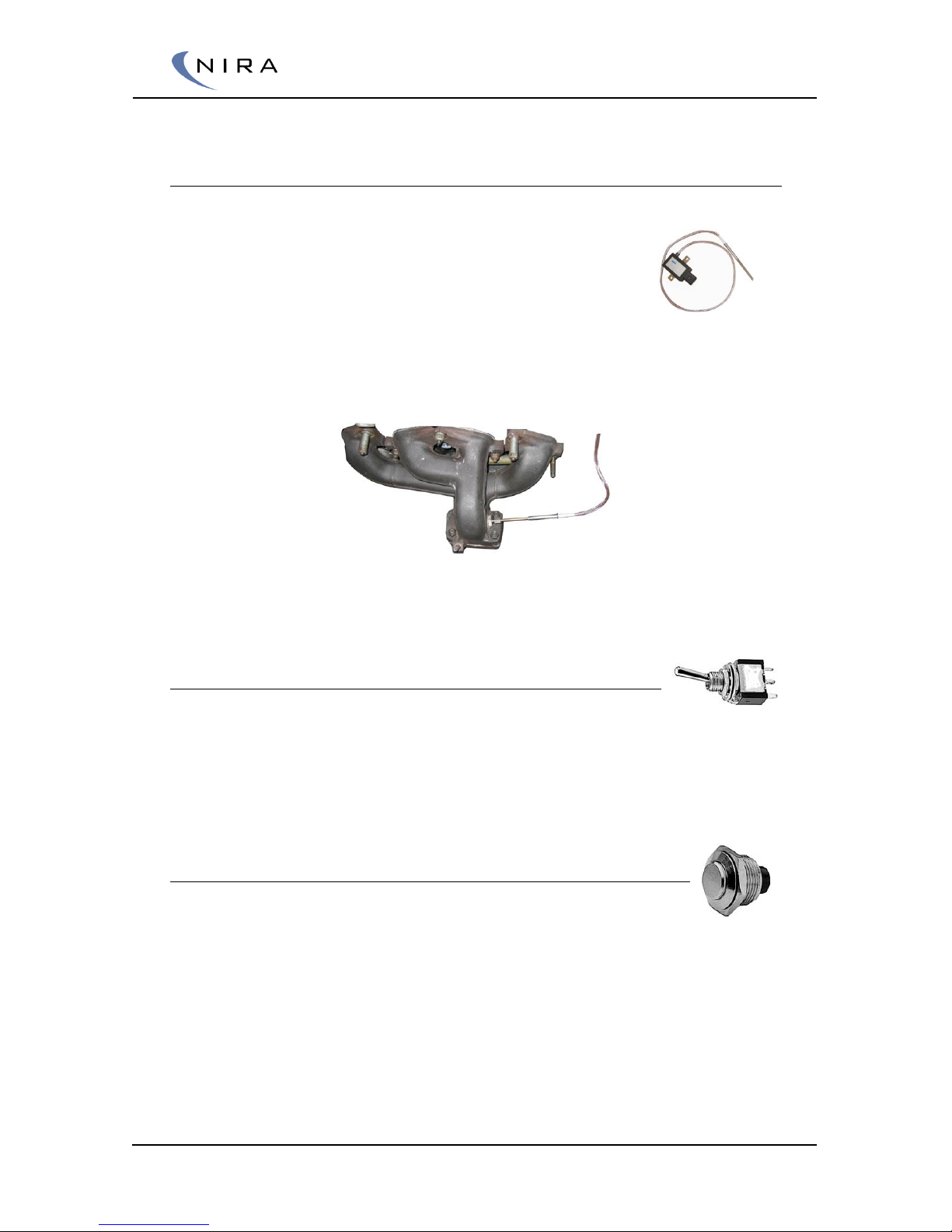
Being able to monitor the exhaust gas temperature is very important,
especially on a turbo charged engine, in order to avoid
engine damage and also to avoid over-cooling the
combustion with too much injected fuel as this lowers
engine power. The ALS feature of NIRA i7x also requires
precise monitoring of the exhaust gas temperature.
Make frequent inspection of the sensor to make sure it is in order. A broken
sensor will immediately destroy the turbo.
Picture 3-5: The NIRA EGTC sensor probe mounts where the headers collect, before the
turbo.
3.10 Anti Lag System (ALS) Switch
An external switch is needed to turn on/off the Anti Lag System. Mount the
switch so it’s easily accessible for the driver. Connect two wires to the switch.
The Button GND wire at one of the pins. The other pin connects to the wire
marked “ALS Switch in, on=gnd” in the NIRA i7x harness.
3.11 Launch Control Button
A button is needed to activate Launch Control. Mount it so it’s
easily accessible for the driver. Connect two wires to the button. Ground one
of the pins with the “Button GND” cable. The other wire connects to the wire
marked “Launch Button in, on=gnd” in the NIRA i7x harness.
Page 33

© 2005-2016 Nira Control AB 33
3.12 Aux Inputs
NIRA i7x is equipped with eleven Aux Inputs. All these inputs can be used in
NIRA i7x FlexiPortsTM for user defined outputs or compensations.
Two 0-5 Volt Analog input
One 0-12 Volt Analog input
Four Resistance reading 0-32 kOhm
Two Resistance reading 0-3200 Ohm
Two Digital input. Period time and duty is measured
3.12.1 Input Filters
All inputs to NIRA i7x, including the Aux inputs, can be filtered using the
“Advanced” setting in NIRA rk.
Sometimes this is useful when dealing with noisy input signals in order to
improve readability during data logging.
Before applying filtering to MAP, MAT and TPS inputs, make sure that you
have an understanding of the effects of adjusting the filter. These input
signals should normally never need to be filtered.
3.13 Ignition
NIRA i7x is designed to drive multiple ignition coils, either with
built-in (active coil) or external drive electronics (for passive coil).
The ignition output signal from NIRA i7x is a signal between 0 and
5 Volts and triggers on a negative flank, i.e. when the signal goes
from 5 Volts to ground.
NIRA i7x can control the ignition of up to eight cylinders without waste fire.
Ask your NIRA i7x dealer about high performance ignition coils
Ignition Coil Power Supply
Modern active coils consume a great amount of energy during dwell-time. At
the end of the dwell time the current can reach values of nearly 20 Amperes.
With increased rpm the dwell times are overlapping each other and the total
current consumption increases even more. Make sure the coils are supplied
by a sturdy relay with fuse. Connect with appropriate cable dimensions and
well crimped terminals for both supply and ground wires.
Page 34
© 2005-2016 Nira Control AB 34
3.14 Fuel Pressure Regulator (FPR)
For NIRA i7x to correctly calculate fuel injector on- times, a linear fuel
pressure regulator needs to be installed in the fuel system. In a linear FPR,
the fuel pressure rises linearly as a function of the intake pressure.
When so called progressive or rising-rate regulators are used, FlexiPorts™
should be adjusted in a way that compensates the fuel injection according to
the difference between a linear fuel pressure regulator and a progressive fuel
pressure regulator.
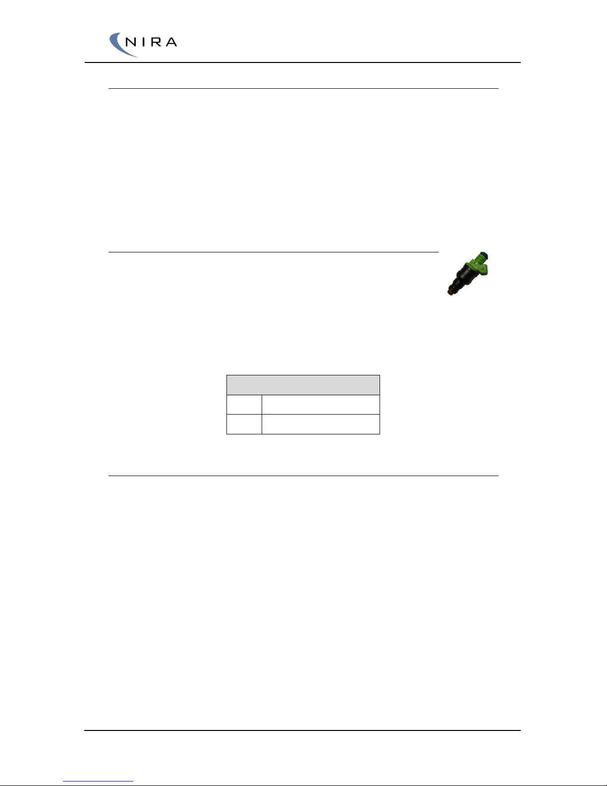
3.15 Fuel Injectors
The fuel injectors are extremely important when tuning a high
performance engine. Thus, choosing injectors with diligence is
necessary. Below are instructions that aim to facilitate the process
of choosing the right injectors for your engine.
For high impedance injectors, connect the wire marked “Fuel Injector X
supply” and “Fuel Injector X” to each injector.
High impedance Injector
Pin 1
Fuel Injector X supply
Pin 2
Fuel Injector
3.15.1 Choosing the Injector Capacity
Do not choose injectors with overly large capacity if there is a need to
calibrate lambda with precision at low-load conditions, e.g. for emissions
tests.
No injectors are manufactured with high enough precision to avoid
fluctuations in the injected amount of fuel due to temperature and other
running conditions, especially when the fuel injector on-time is less than
1.5ms.
A good rule of thumb when sizing injectors is 500 cc/ 100 hp. I.e. 400 cc
injectors on a 5-cylinder engine is enough for approximately 400 hp unless
lots of additional fuel is needed to cool the combustion.
NIRA rk will automatically alert you if the injector ”bottoms out” and can’t
supply enough fuel. The alarm is called ”DG Max Total Fuel Time”.
Page 35
© 2005-2016 Nira Control AB 35
3.15.2 Type of Injectors
NIRA i7x is designed to drive up to eight fuel injectors sequentially. Injectors
for port fuel injection are ground controlled. Connect one of the injector
terminals to +12 V (terminal 15 via Main Relay) and the other to one of the
wires marked “-Fuel Injector 1-8” in the NIRA i7x harness. In sequential
mode, on engines up to eight cylinders, keep it simple by using the wire
marked “-Fuel Injector 1” for cylinder 1, the wire marked “-Fuel Injector 2”
for cylinder 2 and so on.
If the injector coil resistance is 8,5 Ohm or less, an additional, external
resistor needs to be added to each injector. This is necessary in order to
avoid overheating the injector.
Injectors with coil resistance in the range of 2-5 Ohm work well with a 3.3
Ohm, 15 W resistor in series.
If the series resistance is too high, the injector on-time precision decreases at
low-load conditions and it may be difficult to get the injectors to turn on if
the battery voltage is low.
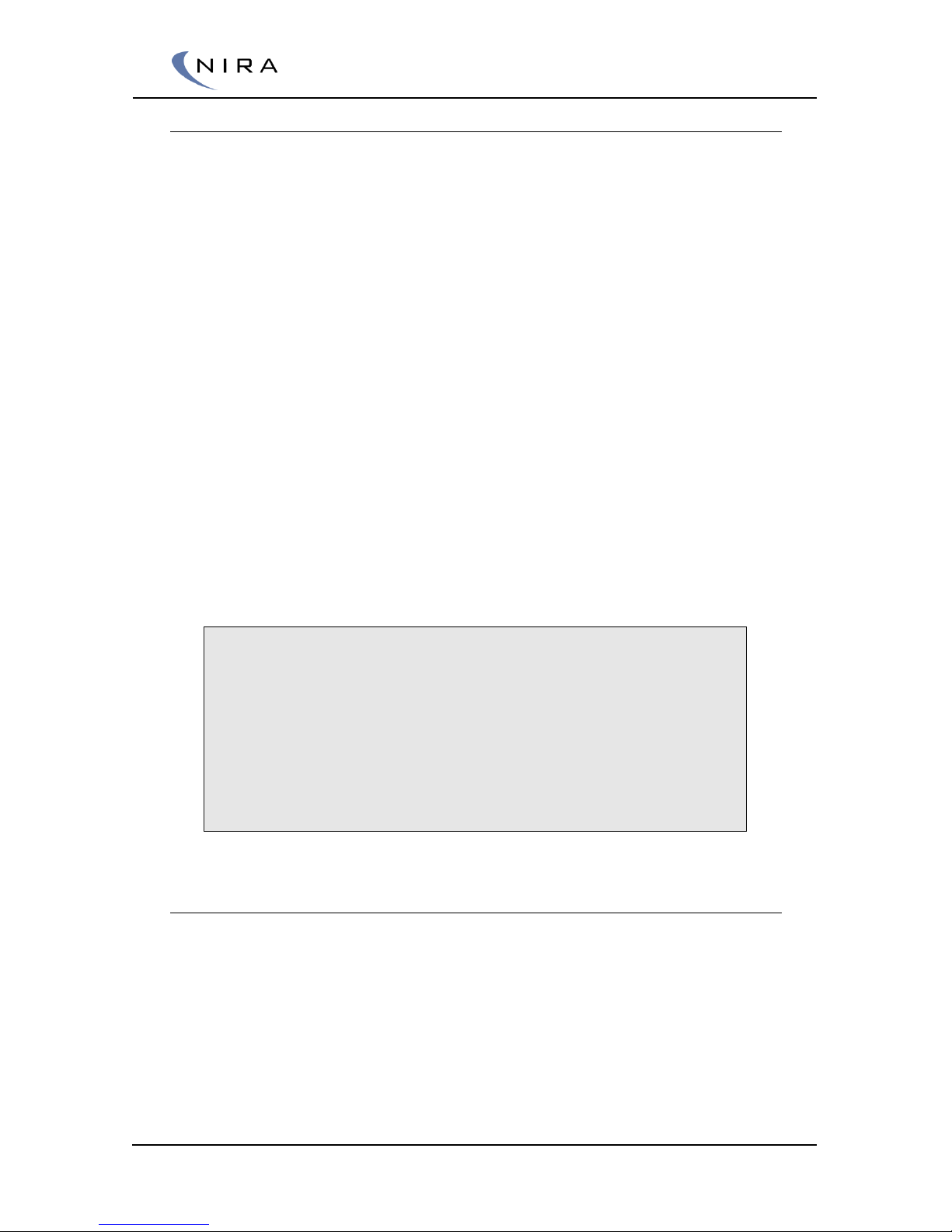
If you would like to calculate the series resistance yourself, use Ohm’s Law
and size the resistance such that the power across the injector is in the range
of 10-25 Watt, assuming normal battery voltage with the engine running
(approx 14 Volt.) Do not go outside this range.
P = Power [Watt], V = voltage [Volt], I = current (Ampere)
(V/sqrt(P/R_injector)) – R_injector = R_series
E.g. R_injector = 3Ω, P = 15 Watt, V = 14 Volt
-> (14/sqrt(15/3))-3 = 3.3Ω.
If you would have chosen 6.8Ω, the injector would only see 6 Watt. At
low battery voltages, such as during cranking, this would result in long,
imprecise injector on times. NIRA i7x has negligible internal resistance
on the injector output lines.
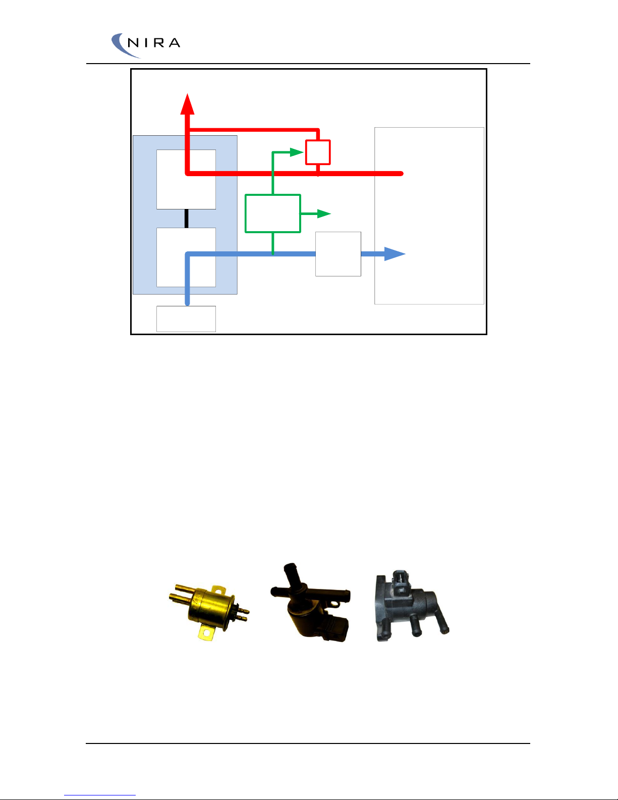
3.16 Boost Pressure Actuator
NIRA i7x is connected to a boost pressure actuator that controls the air-flow
from the inlet to the turbo’s waste gate. By controlling the air-flow,
electronically, NIRA i7x can control the boost pressure in a very accurate
manner.
Page 36
© 2005-2016 Nira Control AB 36
Engine
Turbine
Compressor
Air Cleaner
Throttle
WG
Boost
Actuator
C
R
W
Overview of a boost control system
Boost control actuators have three ports that are connected to
Atmospheric pressure, R (Return). This port is closed whenever the
valve is inactive. When the valve is activated, this port is opened
Pressure after the compressor, C (Compressor). The C-port is
always connected to port W. Generally, the C-port has a visible
restriction
The turbo’s wastegate actuator, W (Wastegate Clock). This port is
always connected to port C
Boost control valves have three port and two or three connection pins
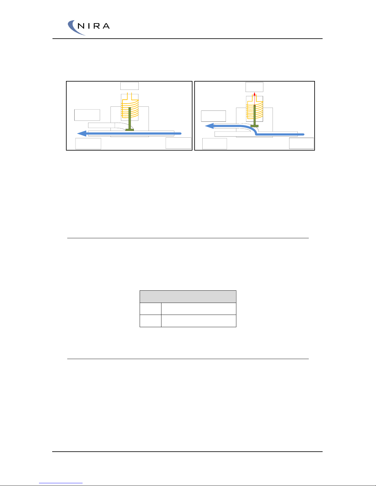
NIRA i7x controls the boost pressure actuator by giving the valve a PWMsignal. A pressure drop that depends on the PWM-signal is created over the
R-port and thus the pressure that reaches the waste gate actuator is
Page 37
© 2005-2016 Nira Control AB 37
controlled. NIRA i7x can be configured to use either a PWM output or an Hbridge output to control the boost pressure actuator. This configuration is
done using NIRA rk.
Bypass flow through the Boost Pressure
Actuator dependent on the PWM through the actuator coil
Boost control valves either have two or three connection pins. The type of
waste gate used and the type of boost control valve determines how the
valve should be connected.
3.16.1 Boost Control Valve with Two Connection Pins
Connection of the sourcing and ground cables is arbitrary on two pin valves.
If the waste gate clock gives a higher boost pressure when the W-port has a
lower pressure, the cables can be connected according to the table below.
The table below assumes that the boost control valve is made for 12 V
sourcing.
Regular Waste Gate Clock
Pin 1
Boost Actuator supply
Pin 2
Boost Actuator
3.17 IAC (Idle Air Control)
At idle, the throttle butterfly is closed. In order to keep the engine from
stalling, a small amount of intake air must be allowed to bypass the throttle
butterfly. Stable idle speed is achieved by controlling the amount of bypass
air and altering the ignition.
There are several different configurations for controlling the bypass air.
Typically some sort of IAC valve or IAC motor is used. NIRA i7x can control
the IAC valve/motor using an H-bridge.
0% duty
”C”
Compressor
”W”
Wastegate
”R” Return
100%
duty
”C”
Compressor
”W”
Wastegate
”R” Return
Page 38
© 2005-2016 Nira Control AB 38
Some possible IAC valve/motor configurations are:
2-terminal IAC valve
3-terminal IAC reversible motor with 1 coil and 2 windings
3-terminal IAC reversible motor
3.17.1 IAC Electrical Connections
Connect a 2-terminal IAC valve to the harness:
IAC valve pin
NIRA i7x harness wire
1:
IAC +
2:
IAC -
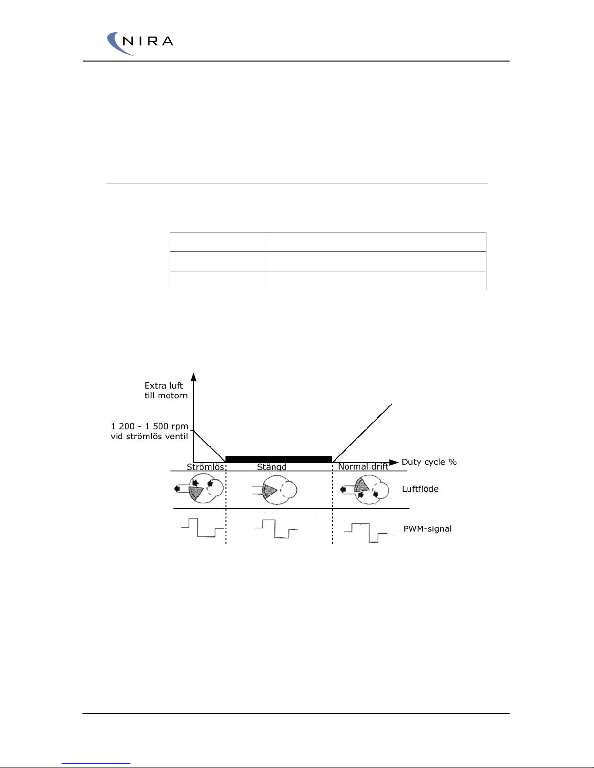
The picture below describes the function of an IAC valve.
Note that at 0% duty cycle, the engine speed is high. The valve closes
completely at around 30% duty cycle and then begins to open again,
increasing engine speed.
Picture 3-6: IAC valve function
The varying duty cycle PWM signal from NIRA i7x is used to modulate the
relationship between the opened and closed states of the valve, thus
controlling the amount of bypass air that reaches the engine.
Page 39
© 2005-2016 Nira Control AB 39
3.18 Main Relay
Use the Main Relay to supply actuators and sensors that need 12 V supply.
Examples of such actuators and sensors could be injectors, CAM sensor, ALS
solenoid etc.
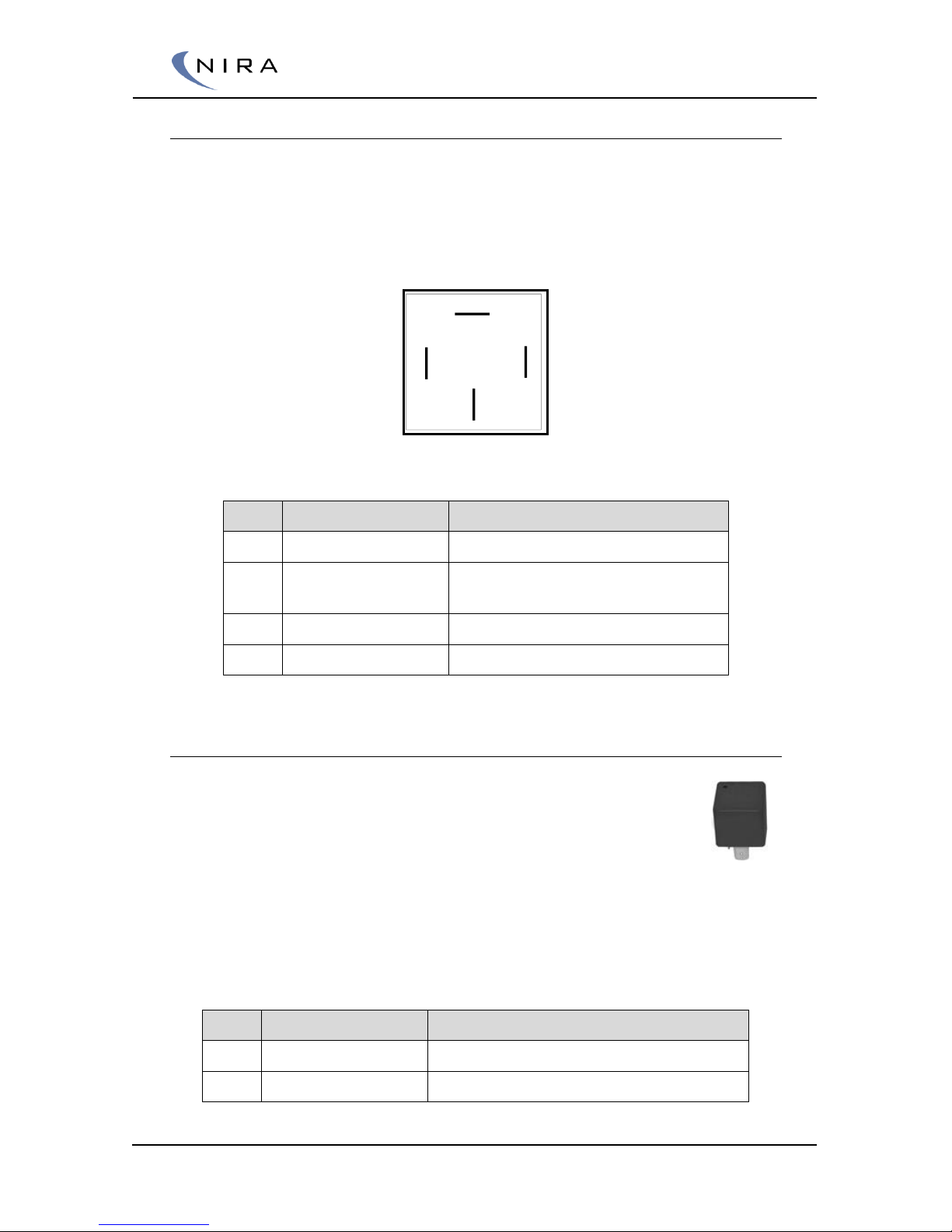
Se the picture below and connect each pin as described in the table.
Kl 87
Kl 30
Kl 86
Kl 85
Relay pin overview
Pin
Description
Connect to
Kl 30
12 V in
Battery. Connect fuse at this side
Kl 87
12 V out
To actuator and sensors that
need 12V
Kl 85
Control solenoid –
Pin V.89 (Main Relay On = gnd)
Kl 86
Control solenoid +
Ign switch (kl. 15)
3.19 Fuel Pump Relay
Warning! Make sure that the fuel pump relay is installed correctly.
An incorrectly installed relay may cause severe personal and
property damage. Do NOT connect the relay directly to the
battery. It must be connected to terminal 15.
Connect one side of the relay coil to terminal 15. Connect the other to the
wire marked “Fuel Relay, on=gnd” in the NIRA i7x harness.
Always connect a fuse with proper rating.
Connect each pin due to table below.
Pin
Description
Connect to
Kl 30
12V in
Battery. Connect fuse at this side
Kl 87
12V out
Fuel Pump
Page 40
© 2005-2016 Nira Control AB 40
Kl 85
Control solenoid –
Pin V.72 (Fuel Pump Relay On = gnd)
Kl 86
Control solenoid +
Ign switch (kl. 15) or Main Relay kl. 87
3.20 Tachometer
A tachometer can be connected to the harness wire marked
“Tachometer Out”. NIRA i7x, pin v.91, outputs a tacho signal similar to a
normal distributor-based system. The pulses are 12 V and can be used to
control most tachometers on the market.
3.21 ALS Solenoid
For the Anti Lag System to work, some sort of mechanism that can increase
airflow to the engine is needed.
One method is to attach a solenoid to the throttle shaft and have the
solenoid open the throttle somewhat. Another method is to add some sort of
valve, which allows air to enter the intake manifold after the throttle plate.
This is analogous to the function of an IAC valve.
If a separate mechanism is used, connect the positive terminal of the
mechanism to Main Relay kl 87 and connect the negative terminal to the wire
marked “ALS Solenoid, on=gnd” in the NIRA i7x harness. NIRA i7x can sink
up to 2A on this pin.
3.22 Wheel Speed Sensors
Four wheel speed sensors can be connected to the ECU to
detect vehicle speed and be used for traction control. The
speed sensors need to be of the type Hall Sensor. This is not
prepared in the wire harness and needs to be added by the
user. Contact your supplier for NIRA i7x connector pins.
Before connecting supply to the hall sensors it is important to know how
much current the sensors draws. This is often stated in the datasheet that
comes with the sensor. Supply can be connected either on E. 7, E.28, V.16 or
V.17. The sensors together should not draw more than 60mA on all the ECU
pins suggested.
Page 41

© 2005-2016 Nira Control AB 41
Connect each pin due to table below.
Nira ix7 Pin
Description
Connect to
E.83 Aux PWM 1
Signal
Wheel Speed Rear Left
E.18 Aux Digital2
Signal
Wheel Speed Rear Right
V.87 Aux RPM 3
Signal
Wheel Speed Front Left
V.70 Aux RPM 4
Signal
Wheel Speed Front Right
3.23 Aux Outputs
NIRA i7x has four auxiliary outputs, marked ”Aux Relay” and ”Aux PWM1 - 3”
in the NIRA i7x harness.
The aux outputs can typically be used to control a nitrous oxide injection
system, water injection, a fan or a shift light. Each aux output can sink max
600mA current. They can not source any current, so if a sourcing output is
required, a pull-up to +5V or +12V is necessary.
Aux Relay is a 1 ampere low side driver for relay with hysteresis function.
Aux PWM1 to AUX PWM3 is user defined PWM outputs controlled by 3d
maps. All Aux PWM’s have different characteristics.
3.24 Mounting NIRA i7x in the Car
Mount NIRA i7x securely in a protected place in the passenger compartment.
Avoid overly hot areas. The maximum ambient temperature without any
cooling fan is 70 degrees Celsius.
If you’ve gone through the installation instructions above, the sensor/actuator
side of the harness is now connected. Now connect the wire marked “ECU
Supply 12V” to Battery through a 30 amp fuse. Connect the wire marked
“KEY” to the ignition switch. Find an ignition switch terminal that’s powered
also during cranking.
Both NIRA i7x harness wires marked “ECU GND” must be connected to
engine ground, either to the block or to the intake manifold. Do NOT
connect the “ECU GND” wires to the body of the vehicle.
Supply the injectors by the NIRA i7x controlled Main Relay.
At this point all sensors needed to run the engine should be installed.
Additionally, the fuel injectors, ignition coils and other parts of the engine
should be installed.
Page 42

© 2005-2016 Nira Control AB 42
In order to be able to start the engine you need to calibrate NIRA i7x using
NIRA rk. To ensure a successful calibration effort, it’s recommended that you
study the NIRA rk sections in the handbook in order to understand how to
use this tool to calibrate an engine before you try to start the engine the first
time.
Page 43

© 2005-2016 Nira Control AB 43
4
NIRA rk Software
NIRA rk is used to calibrate NIRA i7x. NIRA rk is also used to log data for
subsequent analysis while the engine is running. By using NIRA rk and
applying your knowledge of engine tuning you can prepare for the
calibration effort by entering certain parameters for your specific engine. This
gives you a base calibration which will save you time later when you connect
NIRA rk to NIRA i7x.
NIRA rk installs on a PC and connects to NIRA i7x via the Kvaser CAN dongle
connected to your USB port.
4.1 Installation of NIRA rk
Minimum System Requirements:
Windows 98/2000/XP/Vista/7
64 MB of RAM
20 MB disk space (100MB recommended)
800 x 600, SVGA color monitor (minimum 256 colors)
One available USB-port
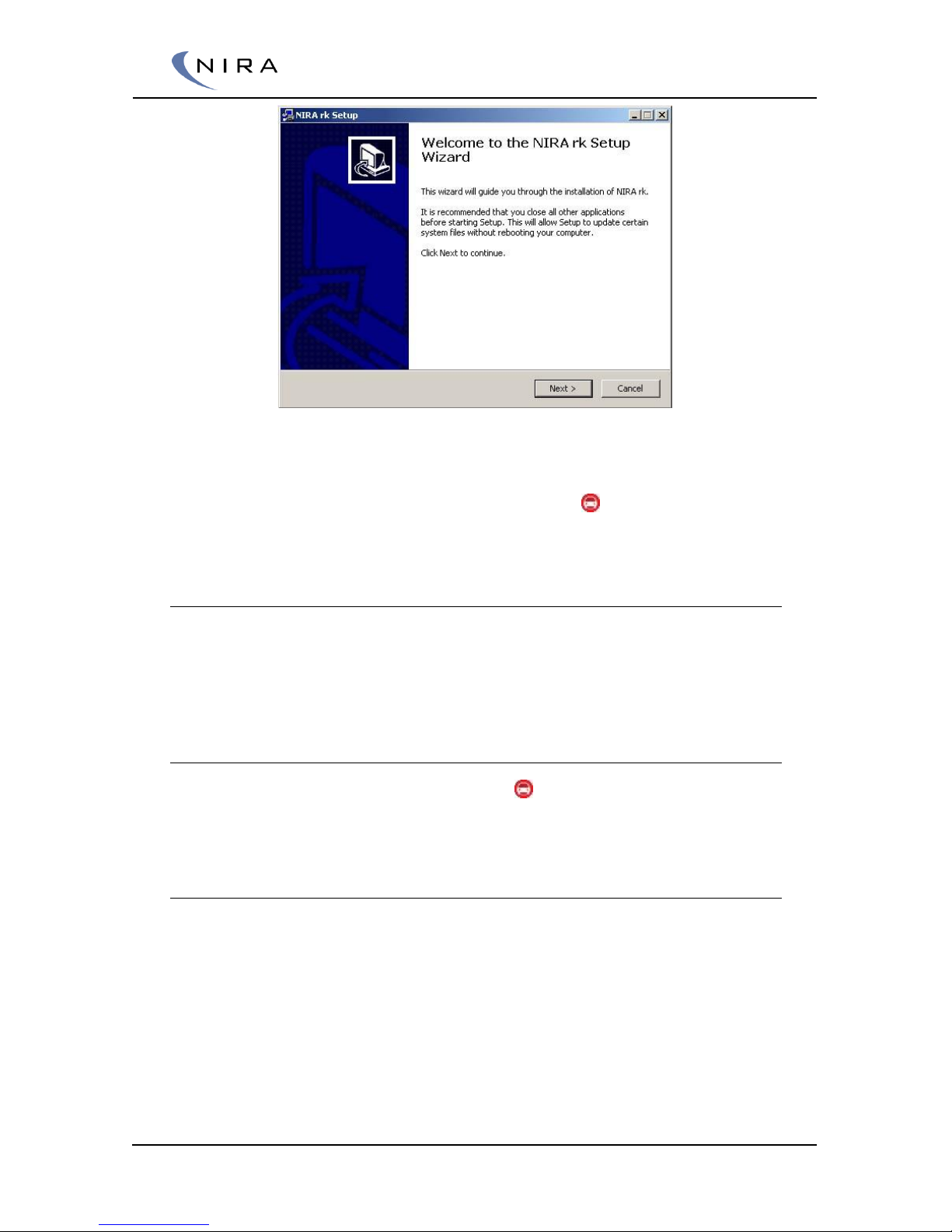
To install NIRA rk on your PC, execute the NIRA-rk.exe file supplied on the
memory stick that is part of your NIRA i7x package. This will launch the NIRA
rk Setup Wizard, which will guide you through the installation process. Follow
the directions in the dialog boxes.
Page 44
© 2005-2016 Nira Control AB 44
Picture 4-1: Setup Wizard used to install NIRA rk.
Once the installation is finished, NIRA rk i7x Street should be listed in your
“programs” list on the start menu. The NIRA rk icon launches NIRA rk.
4.2 Getting Started
This chapter will give you an overview of NIRA rk and its functions. Do not
connect NIRA i7x to NIRA rk until you’ve read this chapter and understand
fully how NIRA rk operates.
4.2.1 Launching NIRA rk
Click on the Nira Race Key Motorsport icon in the installation directory
(default is C:\Nira).
4.2.2 Welcome Screen
Once you have launched NIRA rk, you will see the Welcome Screen.
Page 45
© 2005-2016 Nira Control AB 45
Picture 4-2. Welcome Screen
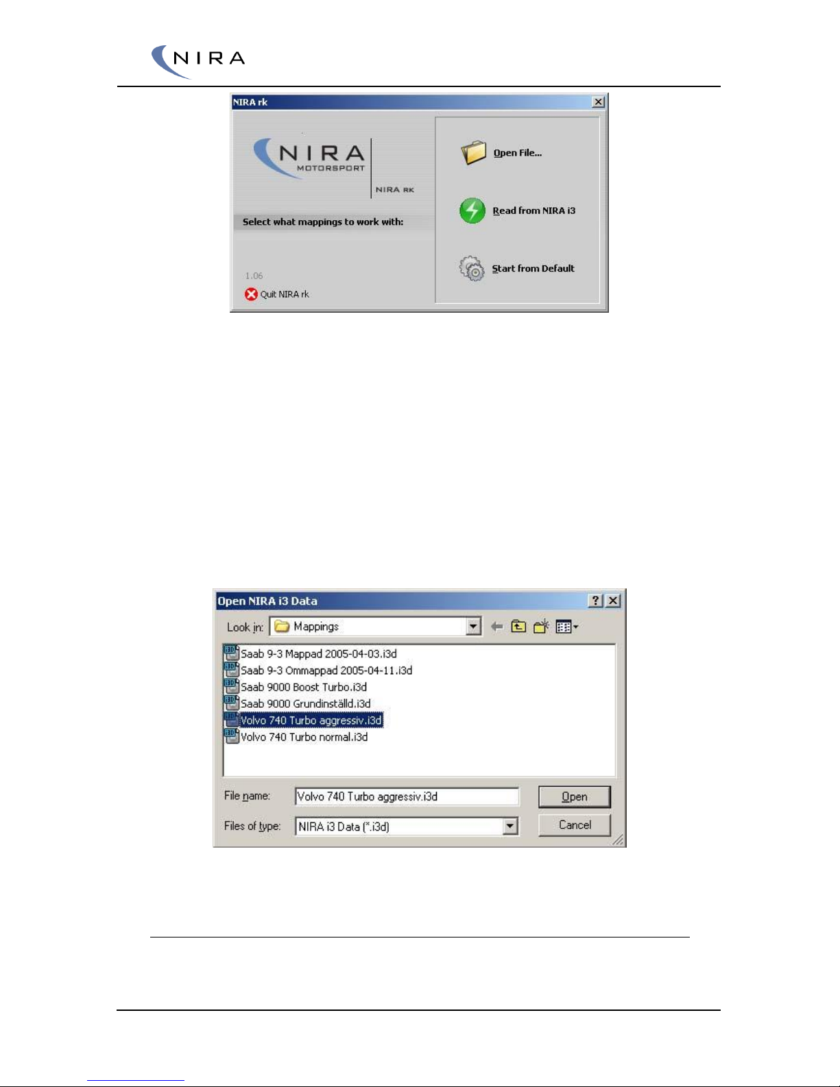
In this screen you can choose among several options. Open File... lets you
open an existing i3d file (a file with calibration data.) Read from NIRA i7x
loads calibration data from NIRA i7x into NIRA rk. Start from Default starts
NIRA rk with default settings.
If you are using an i3d-file supplied by your NIRA dealer, it’s recommended
that you first make a copy of the file before making any changes. This way
you can always return to the original file.
If you select ”Start from Default”, NIRA rk will start in a default mode and all
adjustments have to be done by you.
Picture 4-3: Opening an appropriate i3d.
4.2.3 Wizards
If you opted to start NIRA rk in default mode (see previous section), you must
go through all Wizards before you can load any calibration data to NIRA i7x.
Page 46
© 2005-2016 Nira Control AB 46
This is necessary in order to ensure that you’ve entered appropriate values
for all Engine Setup-parameters before you start mapping. Otherwise, the
calibration effort may be unsuccessful, should it turn out that you’ve been
calibrating with inaccurate basic engine setup parameters.
You can re-run any of the Wizards later, e.g. in order to read the extensive
on-line help available in the Wizards or if you’ve changed one of the sensors.
All Wizards are available under “Wizards” in the main menu.
Any changes you make inside a Wizard only become permanent after you’ve
selected ”Finish” on the last page of the Wizard. You can cancel out of the
Wizard at any time by closing the window (clicking on the “X” in the top right
hand corner of the window.)
It’s very important that you go through all pages of all Wizards and
enter correct values.
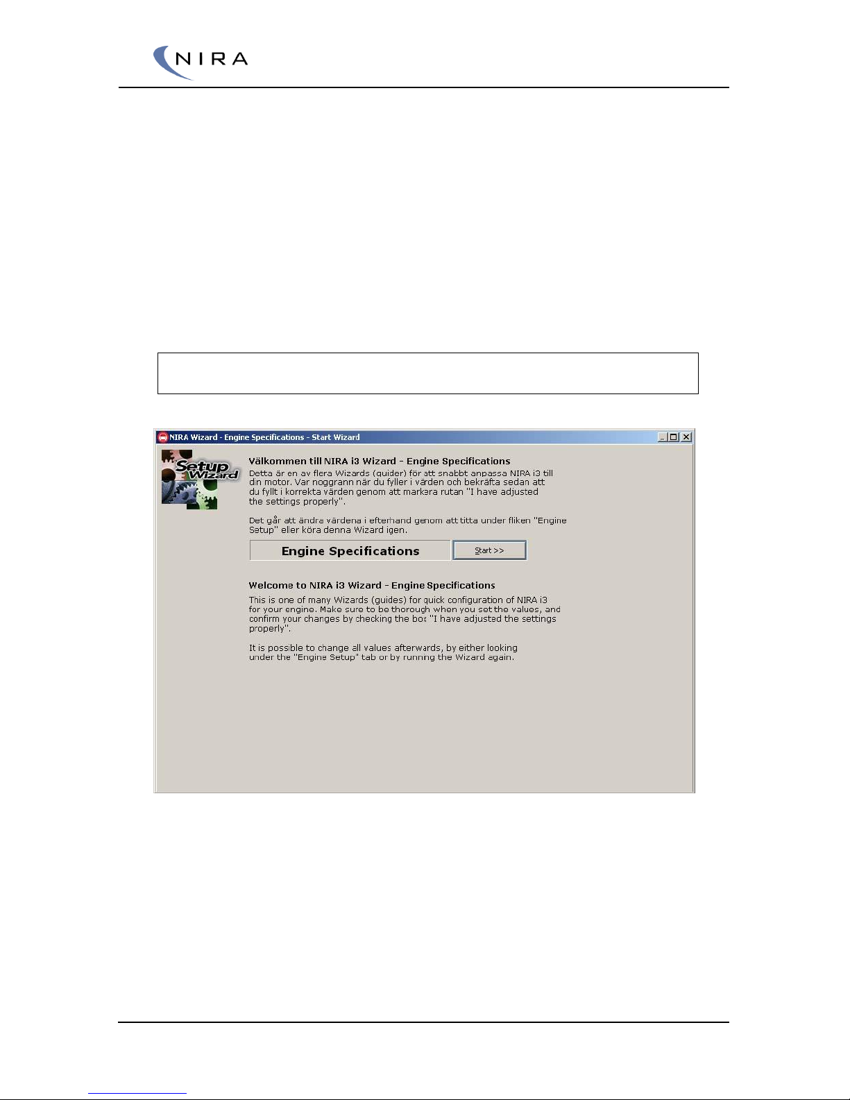
Picture 4-4: NIRA i7x Wizard: Engine Specifications is one of the Wizards you must go
through before you’re allowed to upload data to NIRA i7x.
Once you’ve gone through all Wizards and entered correct values, it’s
recommended that you save all current settings as an i3d-file. Use “Save
As...” under ”File” in the main menu, or hit F4. Try to give the i3d-file a
descriptive name, perhaps including the date, since this will make it easier to
find the file later.
Page 47
© 2005-2016 Nira Control AB 47
4.3 Using NIRA rk
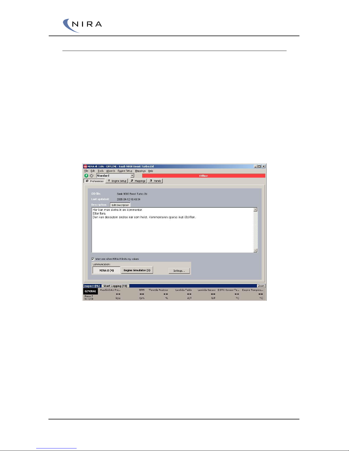
Once you have selected and loaded an i3d-file, NIRA rk takes you to the
Preferences window (Picture 4-5.) This screen tells you when the i3d-file was
last saved on your computer’s file system and you can add comments.
At the top of the main program window, below the main menu, is a red bar
with the word Offline in it. This status bar shows the state of the connection
to NIRA i7x. In order to go online and be able to upload mapping data to
NIRA i7x, you first have to go through all steps of all NIRA i7x Engine Setup
Wizards.
It’s also possible to read any mappings already in NIRA i7x. (“Read from
NIRA i7x” under “File” in the main menu.) Only use this option if you’ve
previously gone online with NIRA i7x.
Picture 4-5: The “Preferences” tab lets you add comments and choose whether you want to
simulate engine running values (Engine Simulator) or connect to NIRA i7x.
Before attempting to connect to NIRA i7x, ensure that the drivers for the
Kvaser USB-CAN dongle are installed on your computer. These drivers are
available on the USB stick delivered together with NIRA i7x.
If you can’t connect to NIRA i7x, check the connection settings by clicking on
”Settings…”. This lets you choose the port to which NIRA i7x is connected.
You can also launch ”Auto Find Target”, which searches all ports and selects
the one to which NIRA i7x is connected.
Page 48
© 2005-2016 Nira Control AB 48
4.3.1 Keyboard Help
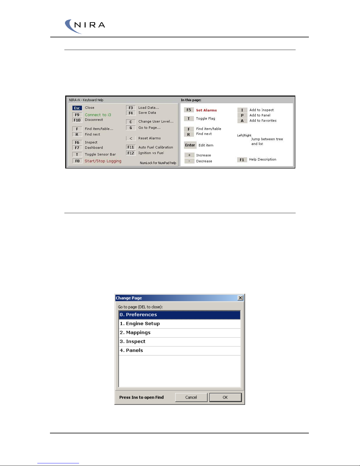
A useful shortcut key to remember is F2. Holding down F2 brings up the
Keyboard Help dialog box. The dialog box shows what can be done in the
current view (and thus, it changes depending on the view.)
Picture 4-6: Holding down the F2 key brings up a window showing all available commands in
the current view.
4.3.2 Tabs
NIRA rk uses tabs to organize different views of parameters, graphs, tables
etc. When a new window is opened a new tab is added. This allows for quick
switching between views. Each new tab gets a number in addition to a name.
You can switch tabs by clicking on the tab with the mouse or by hitting the G
key on the keyboard, which brings up the Change Page dialog box (see
below) and then selecting the desired tab using the up and down arrows on
the keyboard. Shift-G takes you directly to the next tab in order.
Picture 4-7: 'G' (or '5' on the numeric keypad with NumLock off) brings up the "Change
Page" dialog box.
Page 49
© 2005-2016 Nira Control AB 49
You can close a tab by hitting Esc or right-clicking on the tab and selecting
"Close". The first five tabs can never be closed.
While in the Change Page dialog box, you can also close a page by selecting
it and hitting the Del key on the keyboard.
4.4 Parameters
Calibration of NIRA i7x is done by assigning values to parameters in NIRA rk.
There are three main types of parameters:
A monitor: Monitors typically represent physical values, such as RPM,
engine temp etc. These values come from input signals to NIRA i7x.
Monitor values are written in black and are preceded by a blue arrow
. These parameter values cannot be changed. All monitors are
available under the category called “Monitor Output” found on the
left side of the “Mappings” tab
A value: Certain parameters are related to output signals from NIRA
i7x, e.g. to the fuel injectors or the boost pressure control valve. Other
parameters are constants used by NIRA i7x to calculate output signals
or interpreting input signals. Both types of parameters are written in
green and can be changed by the user
A table: Tables are the most powerful parameter type. They are used
for calibrating in- and output signals from NIRA i7x and allow for finetuning of the output signal value based on other parameters. A good
example is the Fm Lambda Target, where lambda values are entered
based on RPM and MAP. Tables are marked by a -icon in front of
the name.
NIRA i7x has a number of tables dedicated to setting up the Aux
outputs, including which input signals are used to control the outputs.
Parameter values written in green can be changed. Those written in black
cannot.
At the left edge of the Mappings tab is a folder view of all available
parameters. The parameters are grouped into logical sets, such as Fuel,
Ignition, Engine Start, etc. Subfolders further separate calibration parameters
to make it easier to find and access the relevant parameters.
NIRA rk starts in Standard mode. If you feel that variables are missing you can
select Advanced mode from the drop down list at the top of the main
Page 50
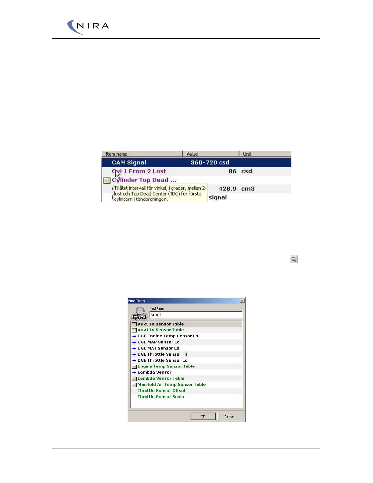
© 2005-2016 Nira Control AB 50
window. This setting exposes more calibration variables. It’s recommended
that you leave the mode setting as Standard.
4.4.1 Sorting and Parameter Descriptions
Parameters can be sorted alphabetically, numerically or according to unit by
selecting Item Name, Value or Unit respectively at the top of the parameter
list. When you move the mouse cursor over a parameter a small help bubble
will appear with information about the parameter. You can also press F1 to
get the same information for any highlighted parameter.
Picture 4-8: A small help bubble appears when the mouse cursor is placed over a
parameter name.
4.4.2 Searching
You can search for a parameter by clicking on the magnifying glass icon ( )
or by hitting F on the keyboard. To go to the next parameter matching your
search criterion, hit R.
Picture 4-9: Searching for a parameter.
Page 51
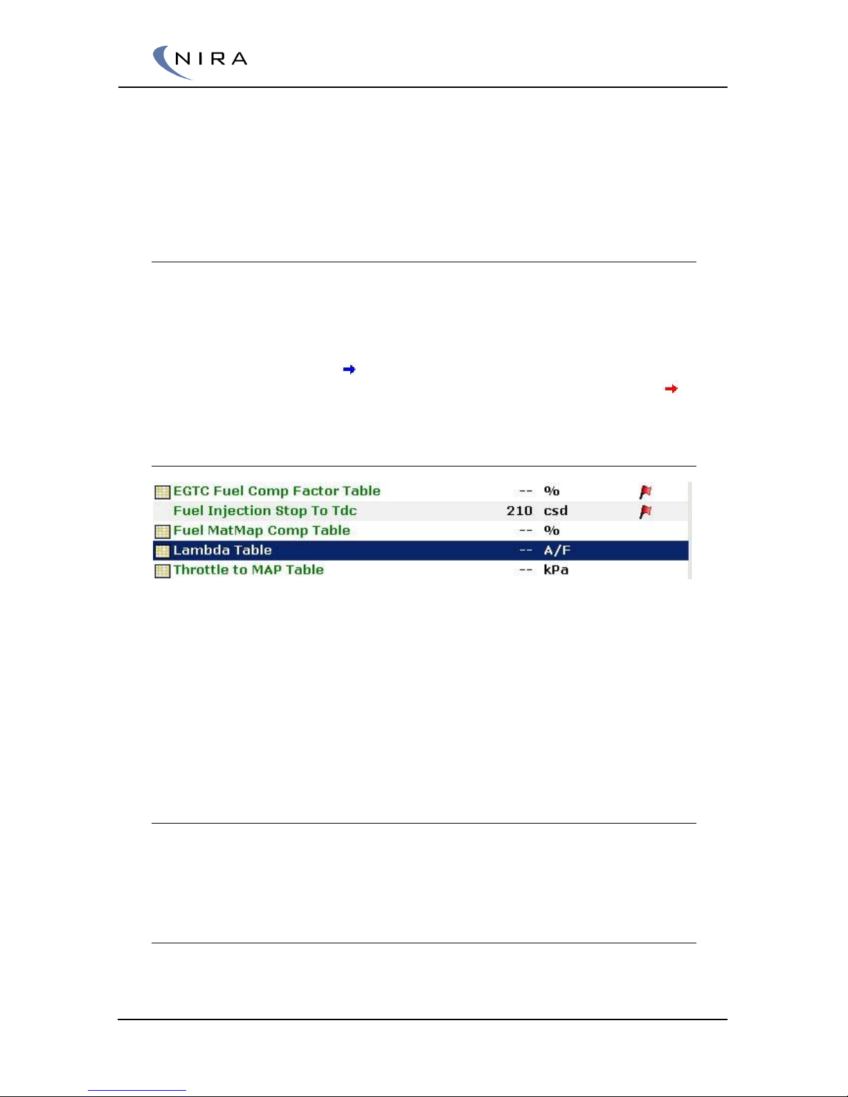
© 2005-2016 Nira Control AB 51
You can search for multiple parts of a parameter name by separating the
search criteria with spaces. E.g. ”th po” gives you a match for ”Throttle
Position” and "sens la" would give you a match for “Lambda Sensor”. As you
type in the letters, the search result is updated continuously.
4.4.3 Alarms
In addition to the built-in diagnostic alarms in NIRA i7x, which, among other
things, check input signal levels, it’s possible to set user alarms using NIRA rk.
Hit F5 or right-click on a parameter and choose “Set Alarm…”.
It’s only possible to set alarms on monitors (see section 4.4.) Monitors are
identified by a blue arrow ( ) in front of the parameter name. Once a
monitor has an alarm associated with it, the arrow changes colors to red ( .)
4.4.4 Flags
As a tool to mark parameters, e.g. which parameters still need calibration,
there’s a flag feature available. Flag a parameter either by clicking in the flag
column of the parameter or by clicking on the “Toggle Flag” button. Monitor
parameters (see section 4.4) cannot be flagged.
All parameters that have been flagged can be viewed in the “Flagged Items”
folder in the tree view to the left. Unflagged parameters can be viewed in the
“Unflagged Items” folder.
4.4.5 Favorites
You can add parameters to a special folder called “Favorites”. This lets you
collect parameters of particular interest for quick access later.
4.4.6 Changing Parameter Values
In order to change a parameter value, highlight it and then hit Enter on the
keyboard. Alternatively, double-click on the parameter name. If you’re online
Page 52
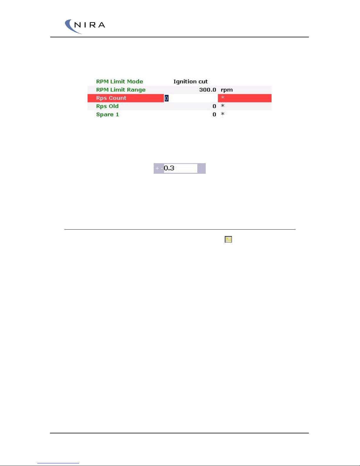
© 2005-2016 Nira Control AB 52
with NIRA i7x at the time, any changes in the parameter value will be
uploaded to NIRA i7x immediately. Otherwise, the changes will be uploaded
next time you connect to NIRA i7x.
Picture 4-10: Double-clicking or hitting Enter lets you change a parameter value.
You can also change the value with the plus and minus keys. Enter the
parameter addition/subtraction in the “+/-“ box above the list.
The delta is unique for each parameter, so if you want the same delta to
apply to a number of parameters, you need to enter this value for each
parameter.
4.4.7 Tables
Some parameter names are preceded by a grid icon ( ). This icon indicates
that the parameter is a table. Tables can be two- or three-dimensional.
Tables control output values from NIRA i7x based on other parameter values.
Typically these parameter values are sensor values, such as rpm or MAP.
Depending on the number of parameter values, the table is one- or twodimensional.
A typical one-dimensional table is the engine temperature sensor. The output
is a function of a single parameter. When you map the temperature sensor
you enter the temperature for different sensor signal voltages.
Page 53
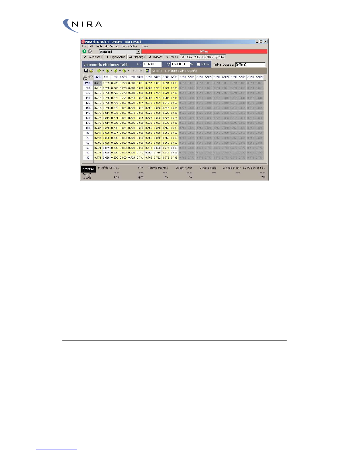
© 2005-2016 Nira Control AB 53
Picture 4-11: A two-dimensional table; it uses rpm and MAP as input variables.
A two-dimensional table uses two input signals; one on the x-axis and one on
the y-axis. The output signal is a function of both input signals, e.g. rpm and
MAP.
4.4.8 Editing Tables
To edit tables, double-click on the parameter name or highlight the name
and hit Enter. A new tab will open up displaying the table contents.
As always, F2 opens a window that lists all possible functions in this view.
There are multiple ways of changing table values. One way is to edit the
content of each individual cell. Right-clicking on a table cell opens up a menu
listing different options for editing the value.
Changing Multiple Cells
To edit multiple cells simultaneously, or have a formula affect multiple cells,
the cells first have to be highlighted. See picture 4-13 below. Highlighting is
done by holding down the left mouse button while moving the mouse, or by
holding down the Shift-key while using the arrow keys to select the cells.
Page 54
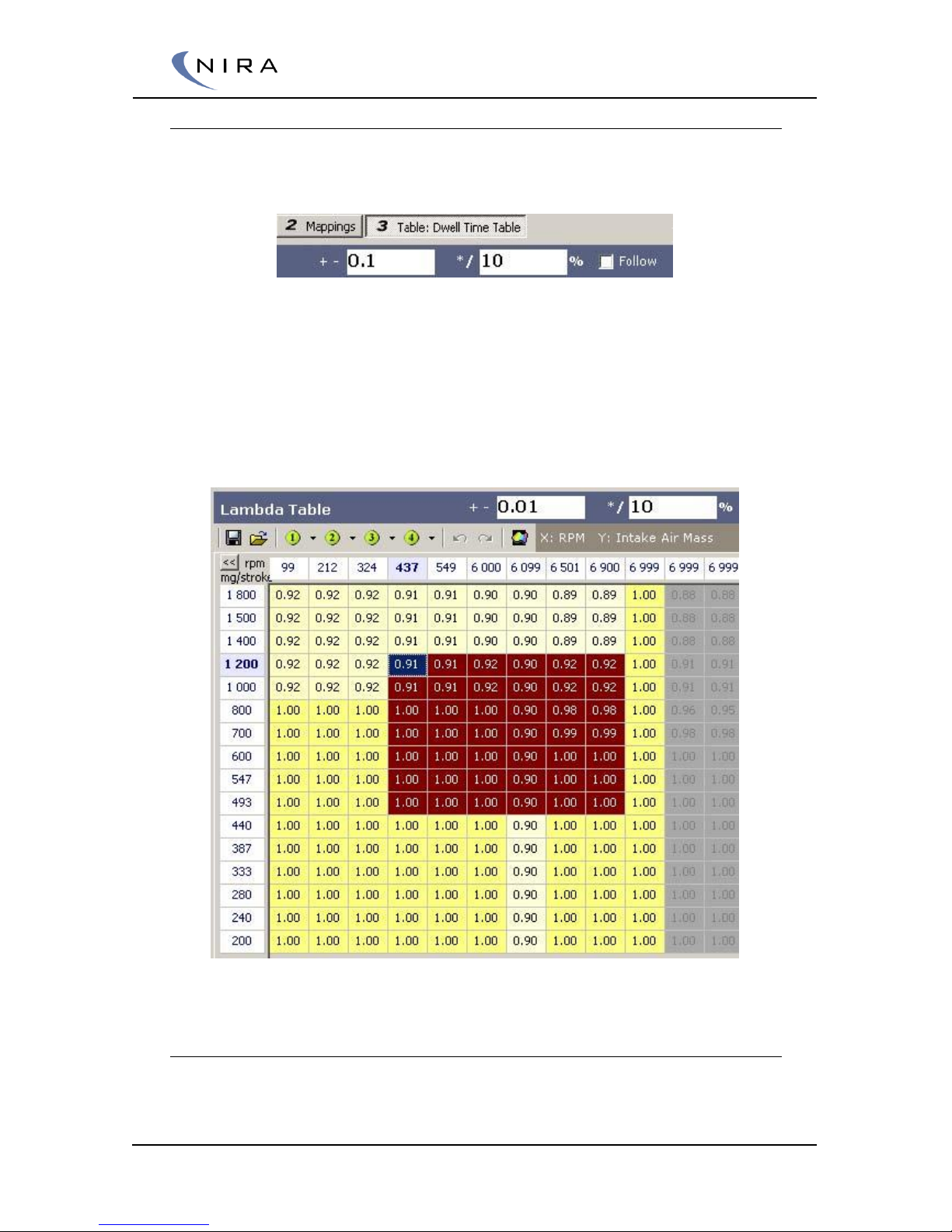
© 2005-2016 Nira Control AB 54
Increasing/Decreasing Cell Values
A simple, straightforward way of working with cell values is to use the +, –, *
and / keys.
Picture 4-12: Enter the delta/ratio increase/decrease for the +, -, * and / keys.
The boxes above the table show the absolute increase/decrease of the cell
values (for the + or – keys) or the %-age increase/decrease of the cell values
(for the * or / keys.) In the case above, the value would increase with 0.1 if you
hit the + key and increase 10% if you hit * key. If multiple cells are
highlighted, they will all be affected.
Picture 4-13: Highlighting multiple cells in a table.
Filling Cells
If multiple cells are highlighted, they can be filled with the same value using a
few different techniques.
Page 55
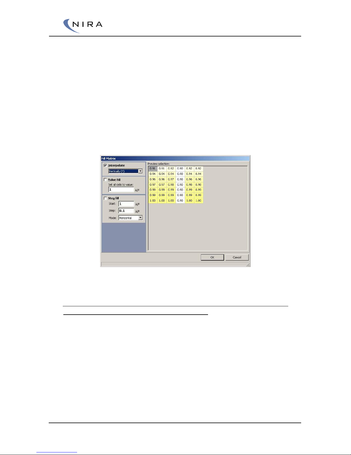
© 2005-2016 Nira Control AB 55
Hit M to set all cells to the same value as the cell in focus. This cell is
blue in the picture above. The color may be different depending on
the color scheme chosen for Windows
Fill cells in one direction. It’s possible to fill cells to the right, to the
left, upward or downward. Choose direction by right-clicking and
selecting “Fill >” from the menu that opens up, or hit Ctrl-R, Ctrl-L, Ctrl-
U or Ctrl-D respectively
More advanced fill patterns can be set up if you right-click and select
“Fill Series...” from the menu that opens up, or hit I on the keyboard.
A dialog box appears in which you can choose to interpolate
horizontally or vertically, to fill all cells with the same value or to fill the
cells with stepwise increasing values in different directions
Picture 4-14: The Fill Matrix dialog box offers more advanced cell manipulation options.
Modifying the Axis Values
The axis values can only be edited in offline mode. Changes applied in NIRA
rk during offline adjustment take effect when the data is loaded to NIRA i7x
by the user going online and choosing update NIRA i7x. Note that the axis
values have to increase monotonously. This means that each value on the xaxis has to be greater than or equal to the previous value as you move to the
right. The same rule applies to the y-axis as you move downward.
For safety reasons, a table that doesn’t follow these rules can not be
uploaded to NIRA i7x and any online connection to NIRA i7x will be
disconnected.
If an axis value is changed, all values in the corresponding column (x-axis) or
row (y-axis) move to this new value. In other words, the mapping values move
to a new axis value.
Page 56
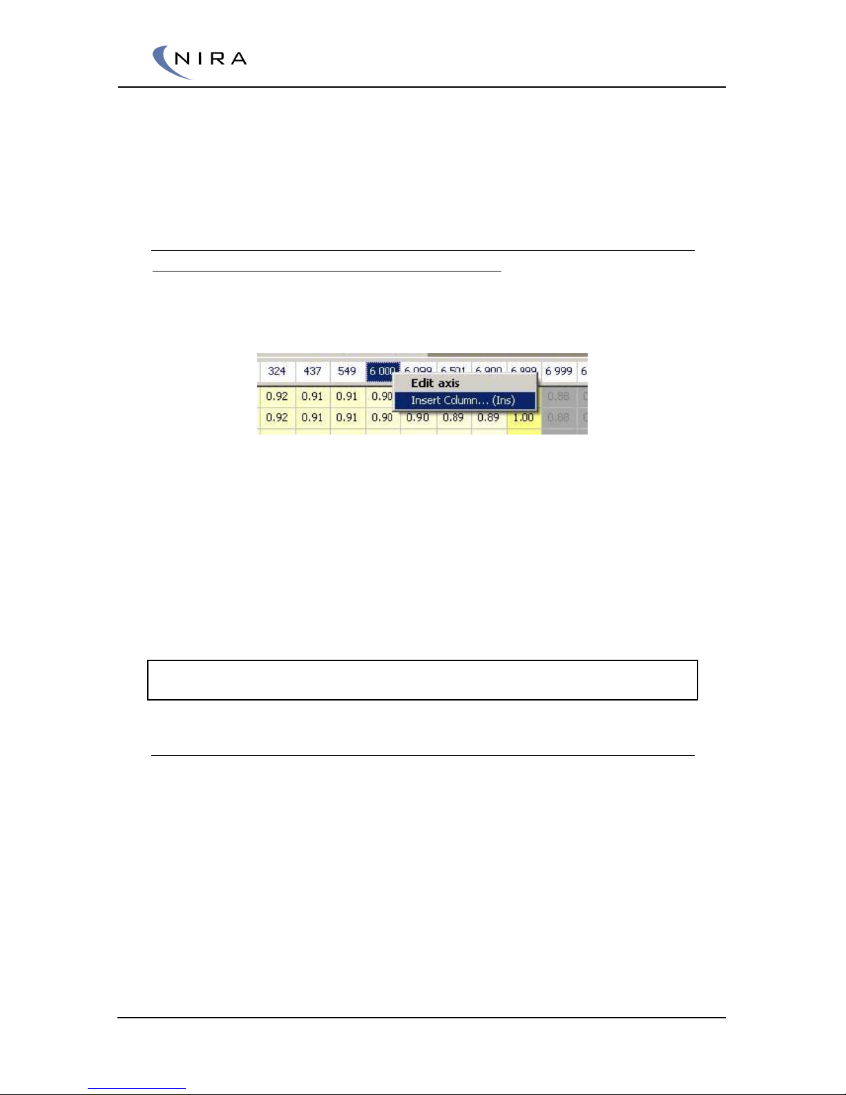
© 2005-2016 Nira Control AB 56
You can switch quickly between the x-axis cells and the table cells by hitting
X or between the y-axis cells and the table cells by hitting Y. The arrow keys
can also be used; if you hit the up key when you’re in the top row of table
cells, you’ll enter the x-axis. The same is true for the y-axis by hitting the left
key when you’re in the leftmost column of table cells.
Adding Axis Values
The axis values can only be edited in offline mode
Modifying the axes often involves adding more points for greater resolution,
rather than moving points around.
Picture 4-15: Inserting an x-axis column in order to add rpm values.
To add more points, right-click on an axis value, use ”Insert Column...” or
“Insert Row…” respectively. You can also hit the Insert key on the keyboard.
Both methods bring up a dialog box in which the new axis value can be
entered. Note that the new value must be between the values to the
immediate left and right or up and down.
The new column/row will automatically get interpolated table values, based
on the new axis value. This way, the overall calibration doesn’t actually
change until you change the table values explicitly.
Note: When a new column or row is added, the rightmost column or the bottom
row will fall off the edge.
Drag Fill; Filling Axis and Table Cells
There’s also a function to fill entire columns or rows, including the axes. This
can be done by dragging and dropping a single axis cell value onto a
different axis cell value. You can also hold down the Ctrl key while using the
arrow keys to perform the same function.
The entire column or row will be marked green. Once you let go of the
mouse button or the Ctrl key, a dialog box will appear in which you can
choose among different fill methods.
Page 57
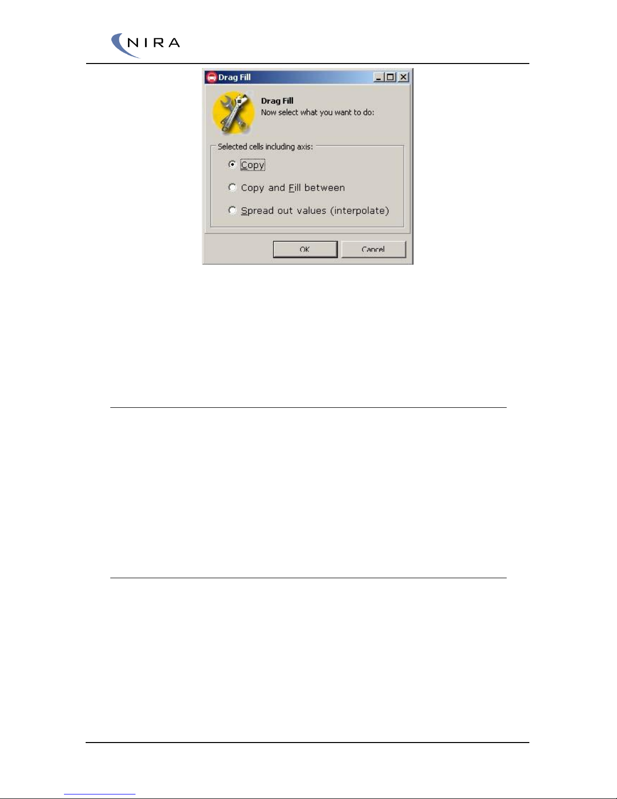
© 2005-2016 Nira Control AB 57
Picture 4-16: Drag Fill: Filling axis and table cells.
When choosing ”Copy”, make sure the result of the copy doesn’t create an
axis with axis values that aren’t all equal or increasing looking rightward (xaxis) or downward (y-axis.) Should this happen anyway, NIRA i7x will go
offline and you need to fix the axis values before you can go online again.
Undo/Redo
It’s always possible to undo any changes you’ve made to a table. As long as
the table is open in a tab, NIRA rk remembers all changes and highlights any
changed cells with an orange frame.
You can also undo undo, as long as you haven’t made any new changes.
This is called redo and is only available if you’ve undone something at least
once.
The standard Windows Ctrl-Z och Ctrl-Shift-Z shortcuts also work, as well as U
for undo och J for redo.
Copy/Paste
It’s possible to copy and paste cells within a table or between tables. You
can also copy and paste from other programs, such as Microsoft Excel.
When pasting cells, you have to mark the cells into which you want to paste
data. This is different from software such as Excel and offers a level of
protection against accidental changes.
Axis cells can also be copied and pasted. Mark the cells with Shift-Left arrow
or Shift-Right arrow or Shift-click with the mouseIt’s not possible to drag and
drop with the mouse due to the Drag Fill function described above.
Page 58
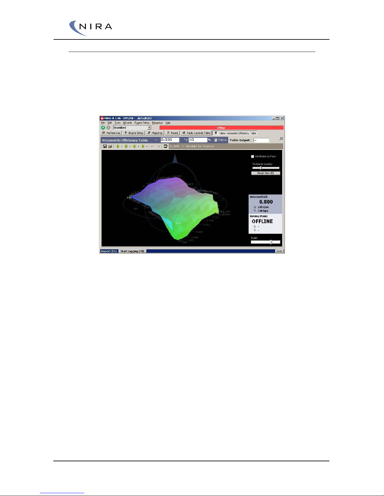
© 2005-2016 Nira Control AB 58
Graphical View
By hitting the F5 key (NumPad: Ins) you can switch to a graphical view of a
table.
The graphical presentation is different for one-dimensional tables and multidimensional tables. Picture 4-17 below shows an example of the graphical
view of a multi-dimensional table where the two axes create a 3-D surface.
Picture 4-17: F5 or the "Toggle Graphics"-button switches to a graphical view of the table.
This is a multi-dimensional table.
One-dimensional tables are shown as graphs. In the graph, the x-axis
represents the axis cells and the y-axis represents the table cells.
Page 59
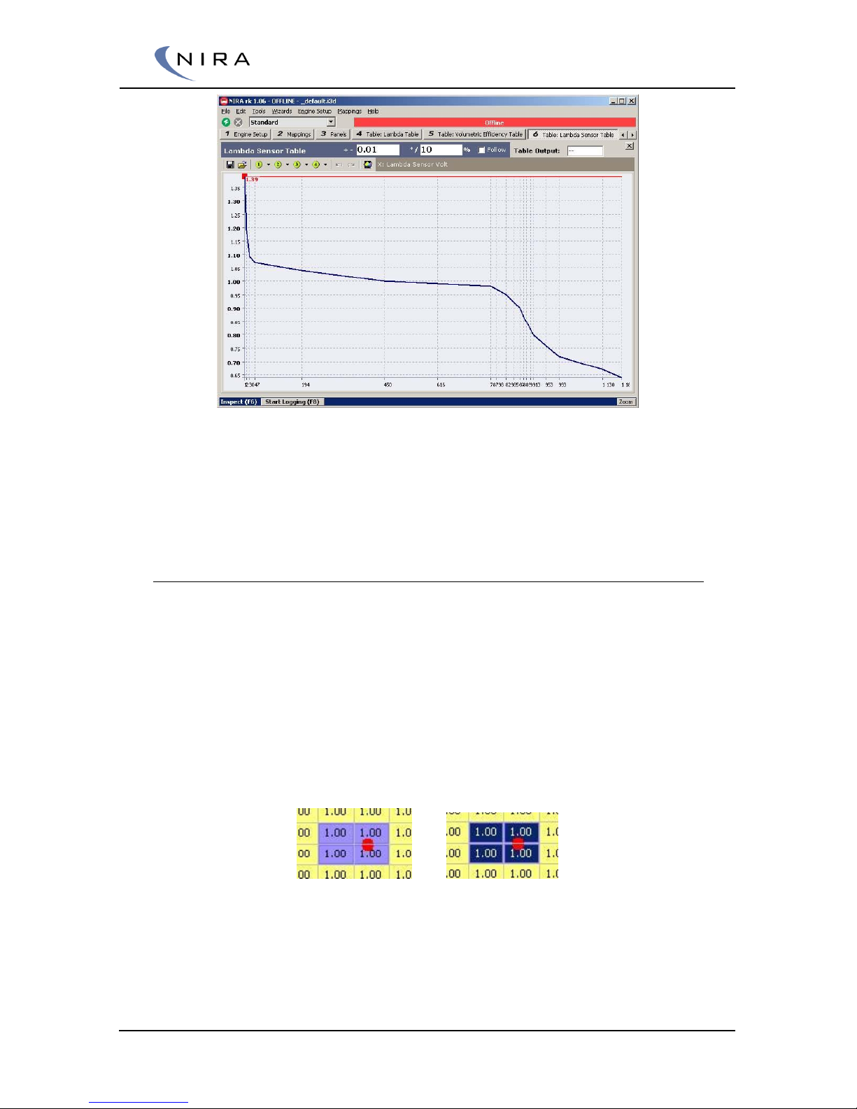
© 2005-2016 Nira Control AB 59
Picture 4-18: F5 or the "Toggle Graphics"-button switches to a graphical view of the table.
This is a one-dimensional table.
While in the graphical view, it’s possible to move among the cells and
change their value with the + and – keys, just like in the table view.
Operating Point
When NIRA i7x is online, NIRA rk can show where in a table NIRA i7x is
currently operating, the so-called operating point. This is very helpful during
the calibration effort.
By checking the ”Follow” checkbox or turning this feature on/off with O,
NIRA rk can move the currently highlighted cell to the operating point.
By hitting Space on the keyboard, you can manually move to the operating
point. This affects all open tables such that the focus of each table moves to
the operating point. If you want to modify multiple tables around the
operating point, this can be very useful.
Picture 4-19: Jumping to the operating point using the Space key.
If ”Follow” is enabled (see above), or if you use Space to jump to the
operating point, four cells around the operating point will be highlighted.
The operating point is marked as a red bullet. If you use the +, –, / or * keys to
Page 60
© 2005-2016 Nira Control AB 60
modify the cell values, they will be modified in a weighted fashion, with
greater weight given to cells closer to the operating point.
Example: In picture 4-19 above, the operating point is farther to the
right than the left and thus, when using the +, -, / or * keys to modify
the values, the cells to the right will be adjusted more than those to the
left.
The operating point is visible in the graphical view as well and the same type
of adjustments described above can be made in the graphical view.
Saving/Opening Tables
It’s possible to save an individual table in a file, an mtx-file. This file can be
opened independently of the global i3d-file.
It’s also possible to associate a particular mtx-file with a quick-access button.
There are four round, green quick-access buttons to the left above the cells
in any open table. They are numbered 1-4. You make the associon by clicking
on the small down-arrow to the right of the corresponding quick-access
button. The file can be loaded later by clicking on the quick-access button, or
by hitting Ctrl-1 through Ctrl-4 on the keyboard.
4.5 PID Controllers
NIRA i7 uses a number of PID controllers.
A general functionality overview follows in this chapter.
4.5.1 What is a PID controller?
A PID controller is named after the Proportional, Integral and Derivative
control modes it uses. PID controllers are used in most automatic process
control applications in industry and automotive. PID controllers can be used
to regulate flow, temperature, pressure, level, and many other industrial
process variables.
Page 61

© 2005-2016 Nira Control AB 61
4.5.2 Feed forward table
Using a feed forward table is a prediction technique that estimates the
output from the proportional-integral-derivative (PID) control algorithm
without waiting for the PID algorithm to respond. If the feed forward
prediction can estimate the control output closely, the PID algorithm, whose
job it is to minimize the error between the current state of the system and the
desired state, will need to do less to correct the error. This reduces the error
faster or keeps the error smaller than relying on the PID algorithm alone.
4.5.3 Proportional factor
The proportional factor is easiest to understand: The output of the
proportional factor is the product of gain and measured error. Hence, larger
proportional gain or error makes for greater output from the proportional
factor. Setting the proportional gain too high causes a controller to
repeatedly overshoot the setpoint, leading to oscillation.
The downside to a proportional-only loop is that when error becomes too
small, loop output becomes negligible. Therefore, even when the
proportional loop reaches steady state, there is still error. The larger the
proportional gain, the smaller the steady state error, but the larger the
proportional gain, the more likely the loop is to become unstable. This
dilemma leads to inevitable steady-state error called offset.
4.5.4 Integral factor
Think of the integral factor as a basket in which the loop stores all measured
error. Remember that error can be positive or negative, so sometimes error
fills the basket (when positive error is added to positive error or negative
error is added to negative) and sometimes it empties the basket, as when
positive error is added to negative, or vice versa.
When the integral factor functions properly in the control loop, the basket is
nearly empty. Even when error is so small that the proportional factor is no
longer effective, the integral is still hard at work, collecting error until it is
large enough to matter, as part of the integral's function is to eliminate
steady-state offset.
In fact, most control loop action at steady state is due to the integral factor.
The downside to the integral factor is that it strongly contributes to controller
output overshoot past the target setpoint. The shorter the integral time, the
more aggressively the integral works.
4.5.5 Derivative factor
The derivative factor is the least understood and used of the three factors. In
fact, a majority of PID loops in the real world are really just PI loops. That
does not negate the fact that there are certain applications in which the
Page 62
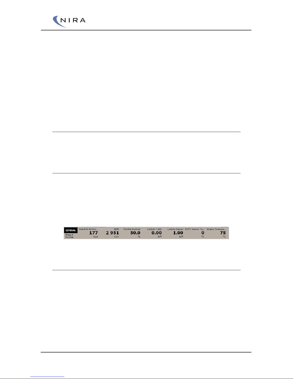
© 2005-2016 Nira Control AB 62
derivative plays a very important role. The proportional corrects instances of
error, the integral corrects accumulation of error, and the derivative corrects
present error versus error the last time it was checked.
In other words, the derivative is looking at the rate of change of the error.
The more error changes or the longer the derivative time, the larger the
derivative factor becomes. The effect of the derivative is to counteract the
overshoot caused by P and I. When the error is large, the P and the I will
push the controller output. This controller response makes error change
quickly, which in turn causes the derivative to more aggressively counteract
the P and the I. A properly used derivative allows for more aggressive
proportional and integral factors. Larger derivative time makes the derivative
more aggressively dampen P and I.
4.6 Gauges
NIRA rk offers a number of different ways to view input signals, e.g. from
sensors.
4.6.1 Sensor Bar
Sensor Bar is the name of the panel at the bottom of the screen. The
selection of parameters in the bar is fixed. However, there are a number of
different Sensor Bars available, each with a different selection of parameters.
Switch among the different types by hitting T on the keyboard until you find
the appropriate one for your current mapping situation. You can also hide the
sensor bar, e.g. if you want the extra space on the screen or if you feel that
other parameters on the screen are updated too slowly.
Picture 4-20: Sensor Bar "GENERAL" contains a set of general parameters.
4.6.2 Dashboard
There’s a predefined dashboard in NIRA rk. It contains a few standard
gauges. The selection of gauges offer an easy general system check, and
they’re also very useful to display on your notebook computer when you’re
testing NIRA i7x in a vehicle or dyno.
Page 63
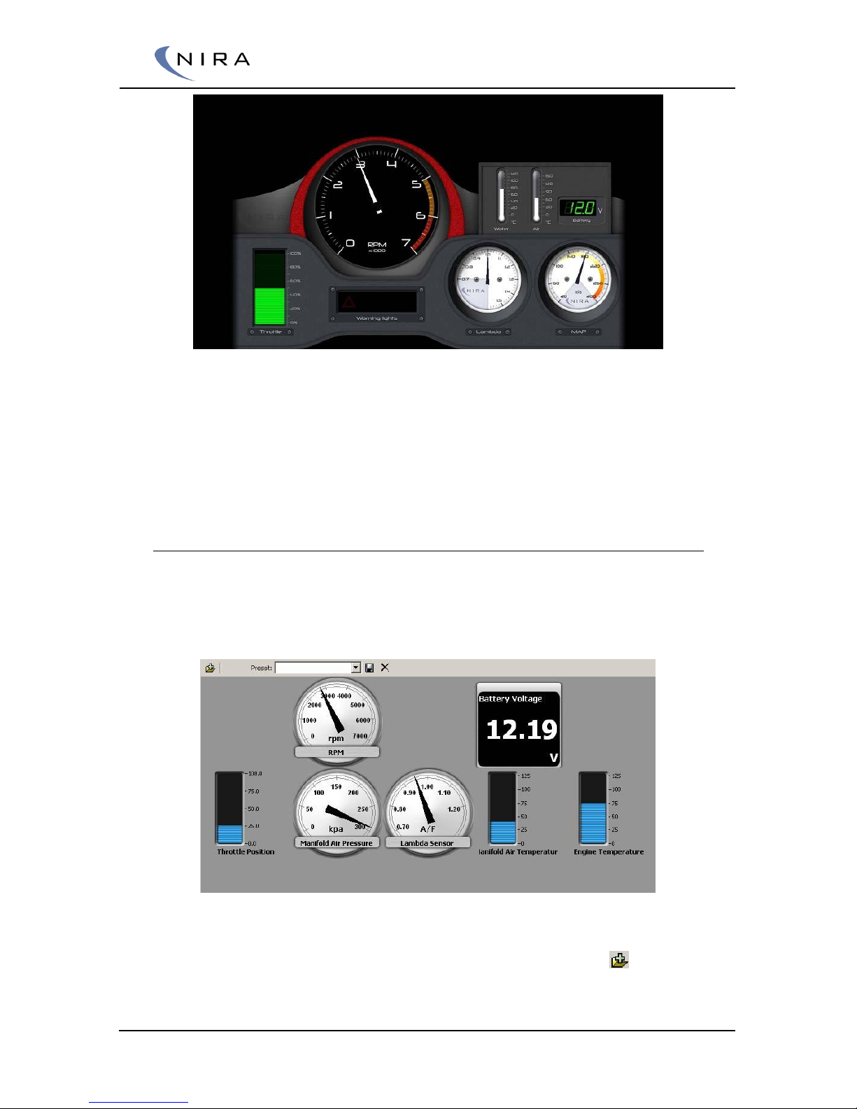
© 2005-2016 Nira Control AB 63
Picture 4-21: NIRA rk Dashboard.
The Dashboard is brought up by hitting F7 on the keyboard. The Dashboard
is available in two versions. The difference is the rpm range. One version
goes up to 7000 rpm, the other to 11000. Choose the most appropriate one
for your engine.
4.6.3 Panels
Unlike the Dashboard, the Panel tab is completely flexible. You can add any
parameter of interest in the form of a gauge. The selection of gauges can be
saved as presets so you can quickly switch among different panel setups.
Picture 4-22: The Panel tab allows you to add any parameter of interest.
To add a gauge to the panel, hit Ins on the keyboard or click on in the
top left corner.
Page 64
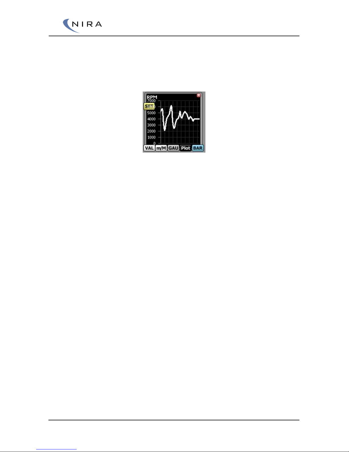
© 2005-2016 Nira Control AB 64
By moving the mouse pointer over a gauge, alternative display options will
be shown as buttons that can be clicked. You can move a gauge by dragging
and dropping the gauge. The panel has an invisible grid to which a gauge
will snap when moved. This makes it easy to create panels with a clean,
organized look.
Picture 4-23: By moving the mouse pointer over a gauge, display options are shown as
buttons that can be clicked.
Referring to picture 4-23 above:
Clicking on the X in the top right corner of the gauge removes the gauge
from the panel.
The buttons at the bottom of the gauge change the look of the gauge:
• VAL means Value. Selecting this option turns the gauge into a simple
value display. The Battery Voltage gauge in picture 4-22 is an example
of the Value look
• m/M means min/Max. Selecting this option turns the gauge into a
Value display (see above) with additional min/Max displays. A Reset
button lets you set the min/Max values to the current value
• GAU means Gauge. Selecting this option turns the gauge into a
traditional analog gauge. The RPM gauge in picture 4-22 is an
example of the Gauge look
• Plot turns the gauge into a histogram, moving from right to left. The
width of the histogram is relatively short, which means it’s mostly
useful for looking at short-duration events. If you want to capture
longer durations and graph them, use the logging feature in NIRA rk.
See section 4.7
• BAR turns the gauge into a bar graph. The Engine Temp gauge in
picture 4-22 is an example of a bar graph
In the Gauge, Plot and Bar modes, there’s a ”Set” button. Double-click on it
or hit Enter to modify the range of the gauge or to revert to the default
range.
As always, F2 opens a dialog box listing all possible short cut keys.
Page 65
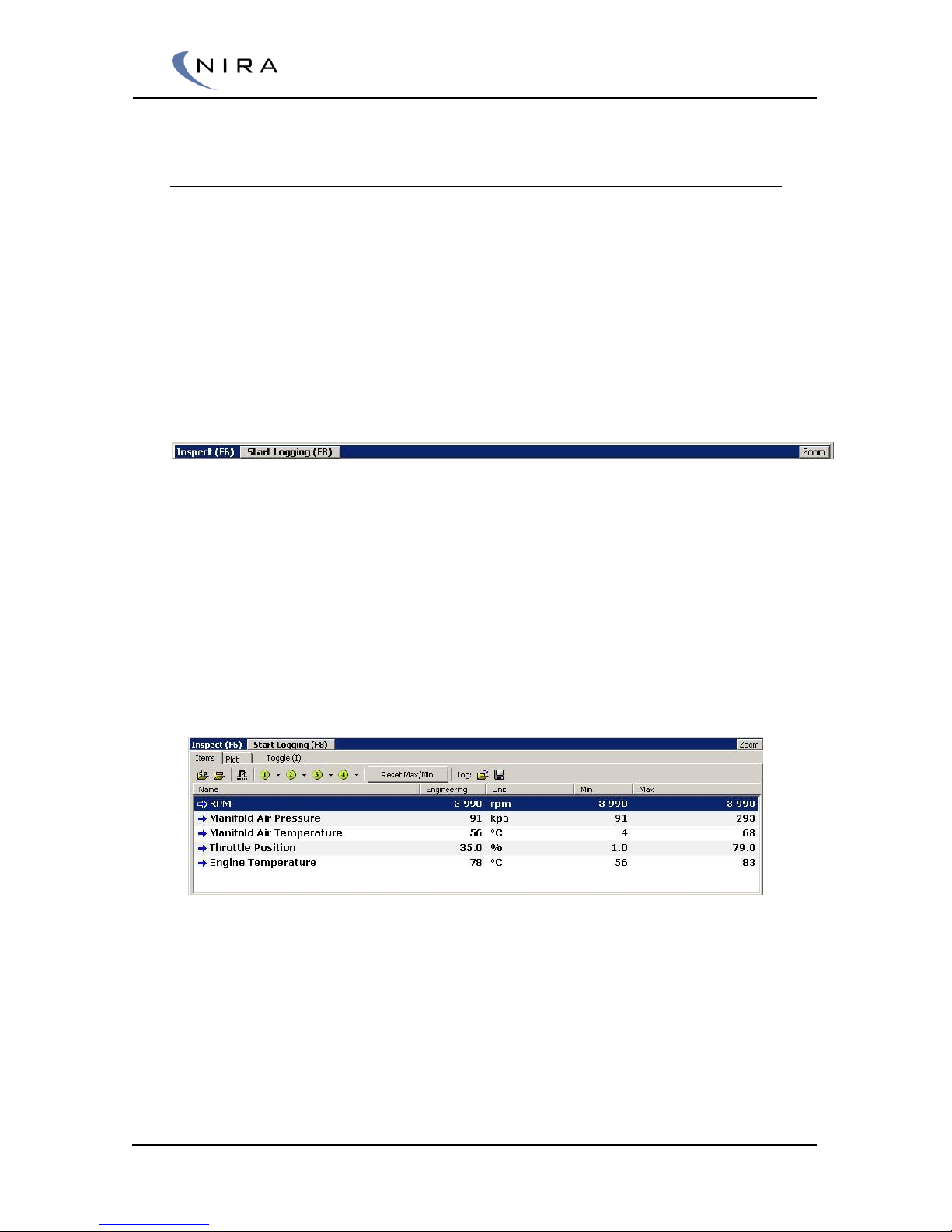
© 2005-2016 Nira Control AB 65
4.7 Logging
NIRA rk includes a powerful logging feature. Any parameter can be logged
and there’s no limit to the number of parameters that can be logged.
However, as the number of parameters increases, the sampling rate
decreases.
The log can be saved to a file and shown graphically.
4.7.1 Inspect
At the heart of the logging function is a function called Inspect. Inspect
allows you to select a set of parameters at which you want to take a closer
look, e.g. by logging them.
Parameters being inspected are shown with min and Max values, even when
actual logging isn’t active. This can be useful when you calibrate your engine.
Inspect resides in a separate window at the bottom of the screen. The
window has three display modes; full view, partial view and minimized view.
You can cycle through the modes with F6, or by clicking on the Zoom button
at the far right of the Inspect window. You can also resize it by clicking and
dragging the top of the window up and down.
Picture 4-24: Inspect. Cycle through the different display modes using F6 or the Zoom
button.
Selecting Parameters
To add a parameter to the Inspect window, highlight it in the Mappings tab
and click on the ”Add to Inspect” button at the top of the window,
alternatively hit I on the keyboard.
Page 66
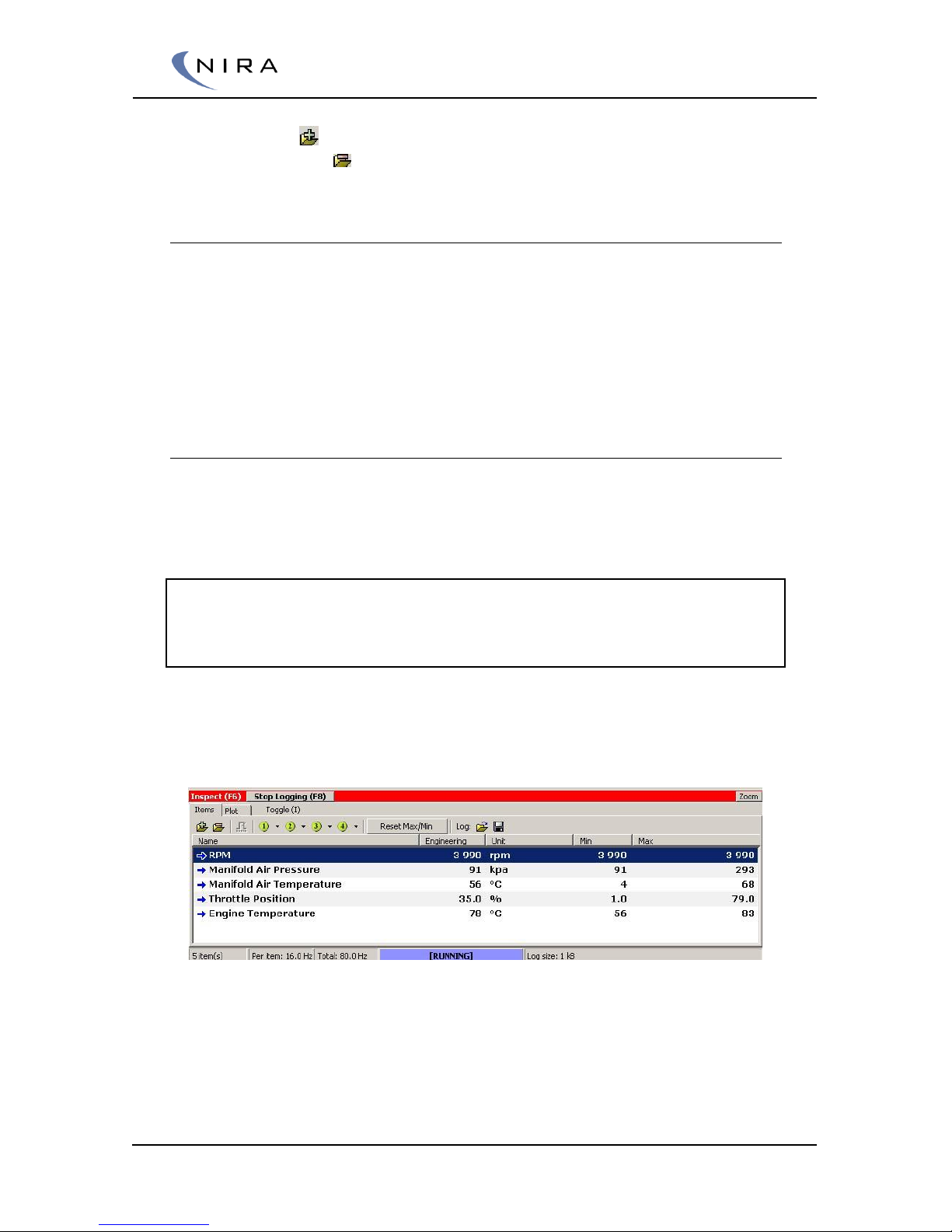
© 2005-2016 Nira Control AB 66
If you would like to add more parameters from within the Inspect window,
you can use the -button. To remove a parameter, use the Del key on the
keyboard or use the -button.
Saving/Opening Presets
It’s possible to save parameter selections and assign them to the four round,
green buttons at the top of the Inspect window. By clicking on the arrow to
the immediate right of a button, a menu will open up giving you the option
of assigning the parameter selection to the button.
NIRA rk comes with four different parameter selections already assigned to
the four buttons.
4.7.2 Basic Logging
To start logging of the parameters in Inspect, hit F8 on the keyboard. This
can be done from anywhere in NIRA rk, whether you’re calibrating a table,
showing gauges or reading help screens.
Note: When logging is active, no parameters are updated in NIRA rk. The
reason is that NIRA rk instead tries to sample the logging parameters as fast
as possible. The operating point is updated, though, and all alarms are still
active.
Parameter values that aren’t being updated while logging is active change to
dashes, "--", so you can always trust any number that’s shown.
Picture 4-25: The top of the Inspect window turns red when logging is active.
To stop logging, hit F8 on the keyboard. This will also open up a dialog box,
which gives you the option of saving the log as a file for later analysis.
Page 67
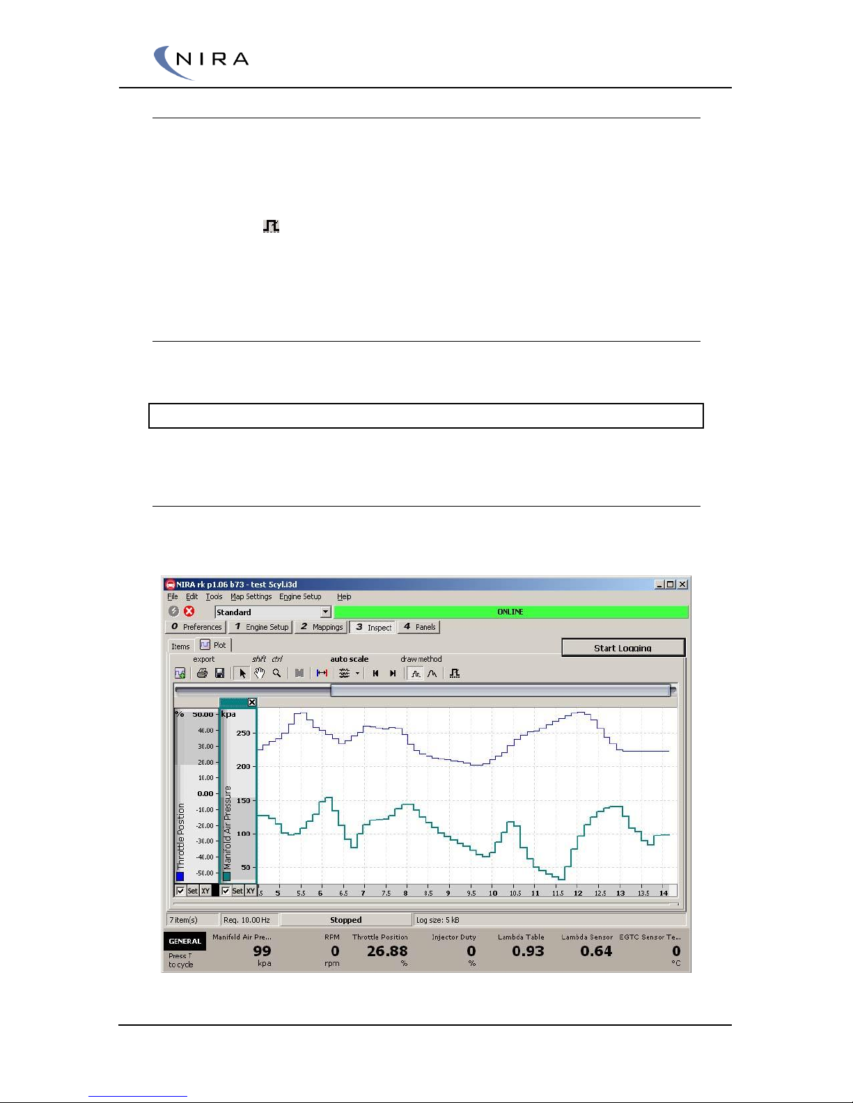
© 2005-2016 Nira Control AB 67
4.7.3 Advanced Logging
Sometimes it is useful to be able to start logging whenever a parameter goes
above or below a certain value. Likewise, it may be useful to stop logging
whenever a certain event happens. For such situations, there’s a trig function
in NIRA rk.
Clicking on the -button or hitting F5 on the keyboard opens up a dialog
box in which you can set conditions for starting/stopping the logging and
how many seconds before/after the trig point you want to be part of the log.
4.7.4 Opening an Existing Log File
You can open an existing log file by selecting ”Load log file…” under File in
the main menu or by hitting Ctrl-F8 on the keyboard.
Note: You can also load NIRA rk log files in MATLAB.
4.7.5 Graphical Presentation
Select the ”Plot” tab to view the logging graphically.
Picture 4-26: Graphical view of logged parameters.
Page 68
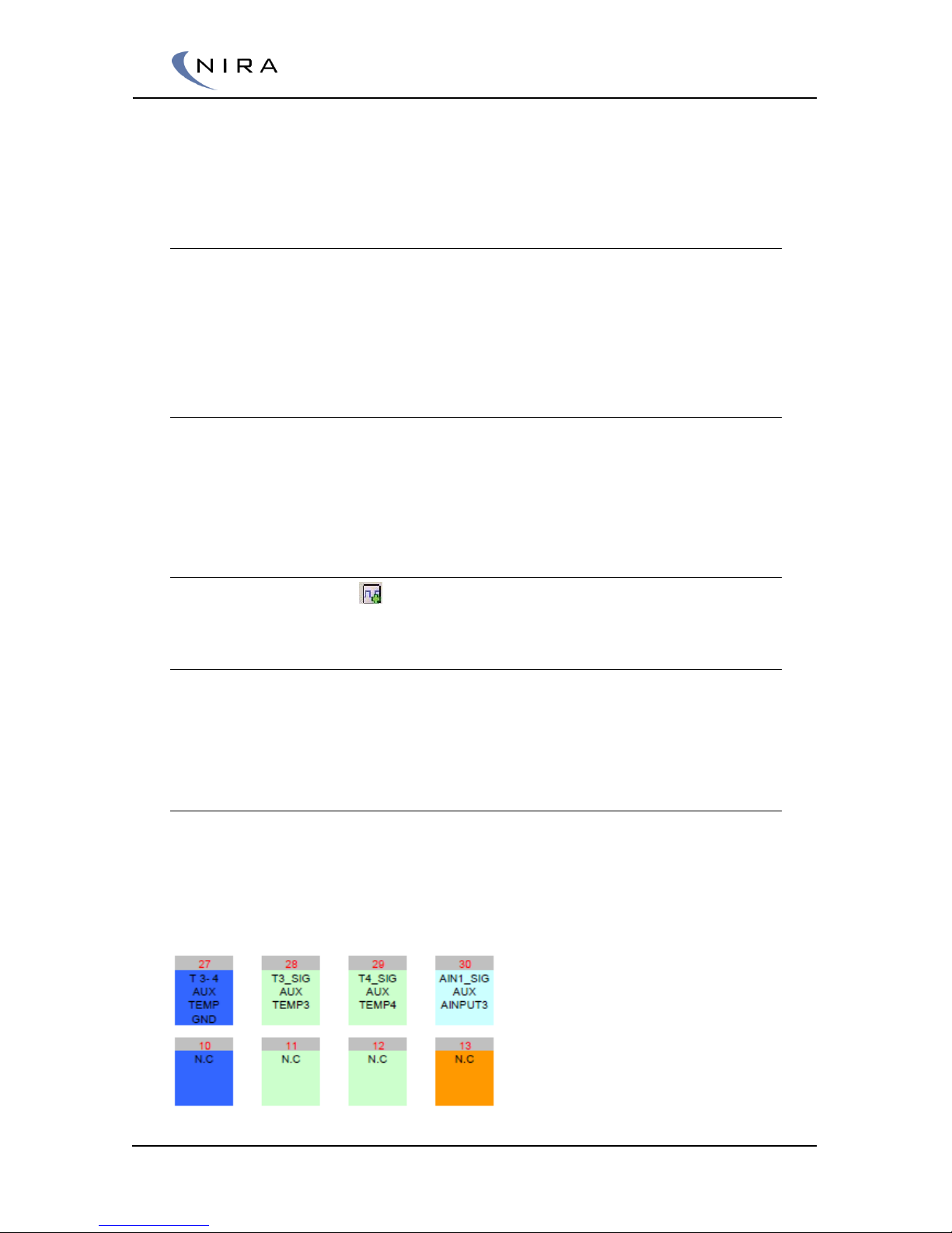
© 2005-2016 Nira Control AB 68
Data from multiple parameters can share the same plot window. Each
parameter has its own, adjustable y-axis at the left edge of the window.
Adjusting the View
There are multiple tools available to zoom and pan. Click and drag on an axis
to pan. Zoom by moving the mouse perpendicularly against an axis.
It’s also possible to adjust the range of an axis by double clicking on the axis
or by clicking on the Set-button at the bottom of each axis.
Removing an Axis
Removing an axis (and the associated sampled parameter) can be done by
clicking on the X at the top right corner of the axis in question. You can
deactivate an axis by un-checking the checkbox to the immediate left of the
Set-button at the bottom of the axis.
Adding an Axis
To add an axis, click on .
4.8 Locking the i3d Data Set
Protect the i3d data file by choosing File Lock i3d Data Set… A password
can be entered that will disable access to the calibration data developed,
unless the password is entered when the data is loaded to NIRA rk.
4.9 FlexiPorts™ - Set up
Example for setting up a FlexiPort for boost controller.
Choose one of the auxiliary temperature inputs and install a switch or
potentiometer to that input.
I.e pin 28. Named T3 in Nira rk.
Page 69
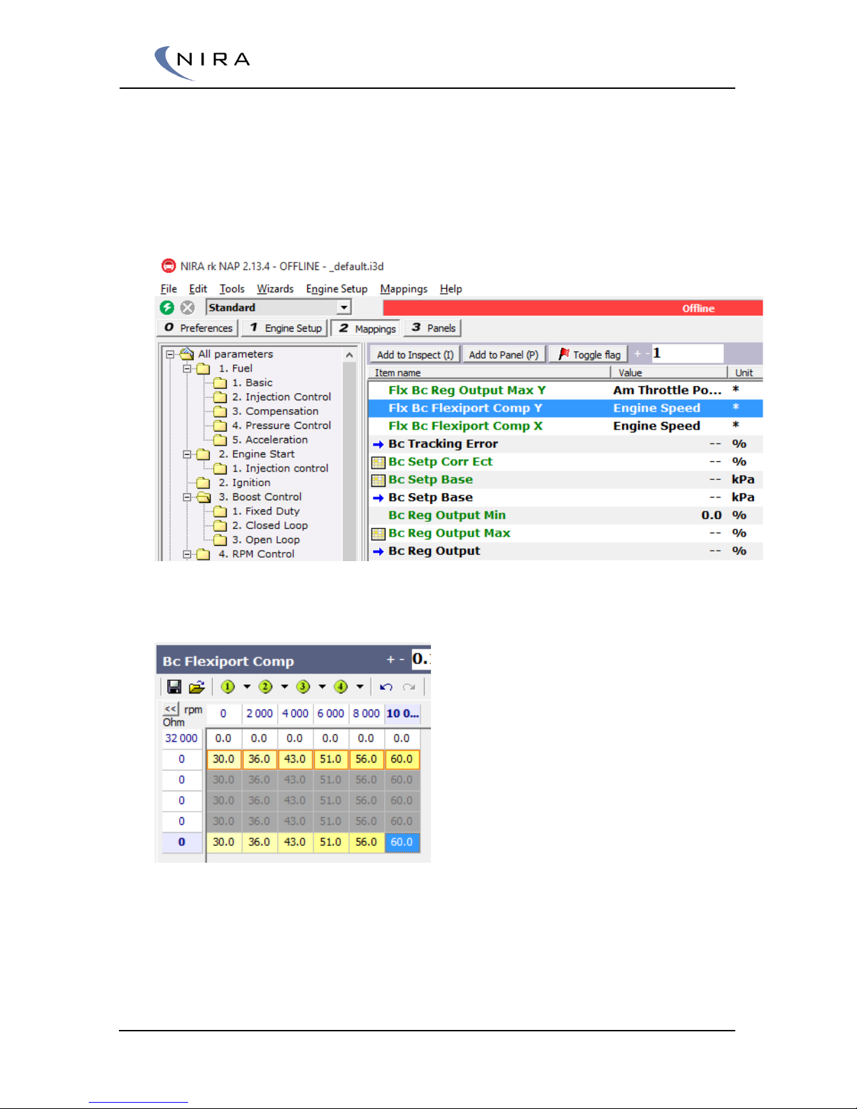
© 2005-2016 Nira Control AB 69
Open Nira rk
- Under Boost Control you will find Flx Bc Flexiport Ff Comp Y.
- Instead of engine speed, choose Ain T3 Resistance to use the T3
input.
- Open the Bc Flexiport Comp and set it up accordingly to your switch
or potentiometer. E.g like below for a grounded switch.
Positive values will be added to the boost setpoint and negative values will
subtracted from the boost setpoint.
If open loop control is used there is a correlating table for that.
Page 70

© 2005-2016 Nira Control AB 70
4.10 Auto Fuel Calibration
Auto Fuel Calibration is a very useful tool when setting up the Volumetric
Efficiency Table. See section 6.3.3 for more information about this table.
To activate Auto Fuel Calibration, hit F11 on the keyboard.
For a complete description of Auto Fuel Calibration, see section 6.3.5.
4.11 Ignition/Fuel Mapping
There’s a special split-view window for the VE and Ignition tables. Hit F12 on
the keyboard to bring up this view. Hit F12 repeatedly to cycle through the
individual tables and back to split view. Hit N to jump between tables in the
split view.
As always, F2 gives you a list of all possible keyboard shortcuts.
5
Starting the Engine
If you’ve read the previous chapters and followed the installation instructions,
NIRA i7x should be installed in your vehicle and you have an understanding
of how NIRA rk is used. This chapter describes how to start the engine in a
safe manner.
Warning! It is absolutely essential that you set up all parameters correctly
under the Engine Setup tab. Failure to do so can easily cause permanent
damage to your engine, and also cause risks of personal injury.
5.1 Setting Up Parameters Offline
Before you turn on the ignition in the car you must set up all parameters
under the Engine Setup tab using the NIRA i7x Engine Setup Wizard. Once
you’ve completed all steps in the wizard you can edit individual parameter
Page 71

© 2005-2016 Nira Control AB 71
values. Make sure you complete all steps in the Wizard before you upload
the settings to NIRA i7x by going online.
5.1.1 Engine Setup -> Crank Cam
It’s essential that the Crank & Cam settings are set properly to get
synchronization of the Crank & Cam relationship. All labels in the “Crank
Cam” folder are named with the prefix “Tpu”. This means that they are
handled by a dedicated part of the CPU. Changing these labels implies that
KEY has to be switched off and on for the changes to take effect.
Crank and cam related labels are found under.
Engine Setup -> Crank Cam
The Crank related labels are:
Tpu Crank Lost Teeth: The numbers of missing teeth at the crank
wheel. For a “60-2” wheel this label should be set to 2
Tpu Crank Polarity: Select which flank on the crank trig that the system
detects. Can be either falling or rising
Tpu Crank Sensor Select: Choose type of crank sensor. Can either be
Hall or Inductive. Note that there are different connections for
different sensor types
Tpu Crank Threshold
Tpu Crank Total Teeth: Number of teeth on the crank trigger wheel.
For a “60-2” wheel this label should be set to 58
The Cam related labels are:
Tpu Cam Polarity: Select which flank on the cam trig that the system
detects. Can be either falling or rising
Tpu Cam Sensor Select: Choose type of CAM sensor. Can either be
Hall or Inductive
Tpu Cam Window Start: From this point the system looks for a cam
sensor transition. The transition should occour whitin number of csd
set in TPU Cam Window Width
Tpu Cam Window Width: Set the distance from TPU Cam Window
Start that the transition should occur within
Page 72
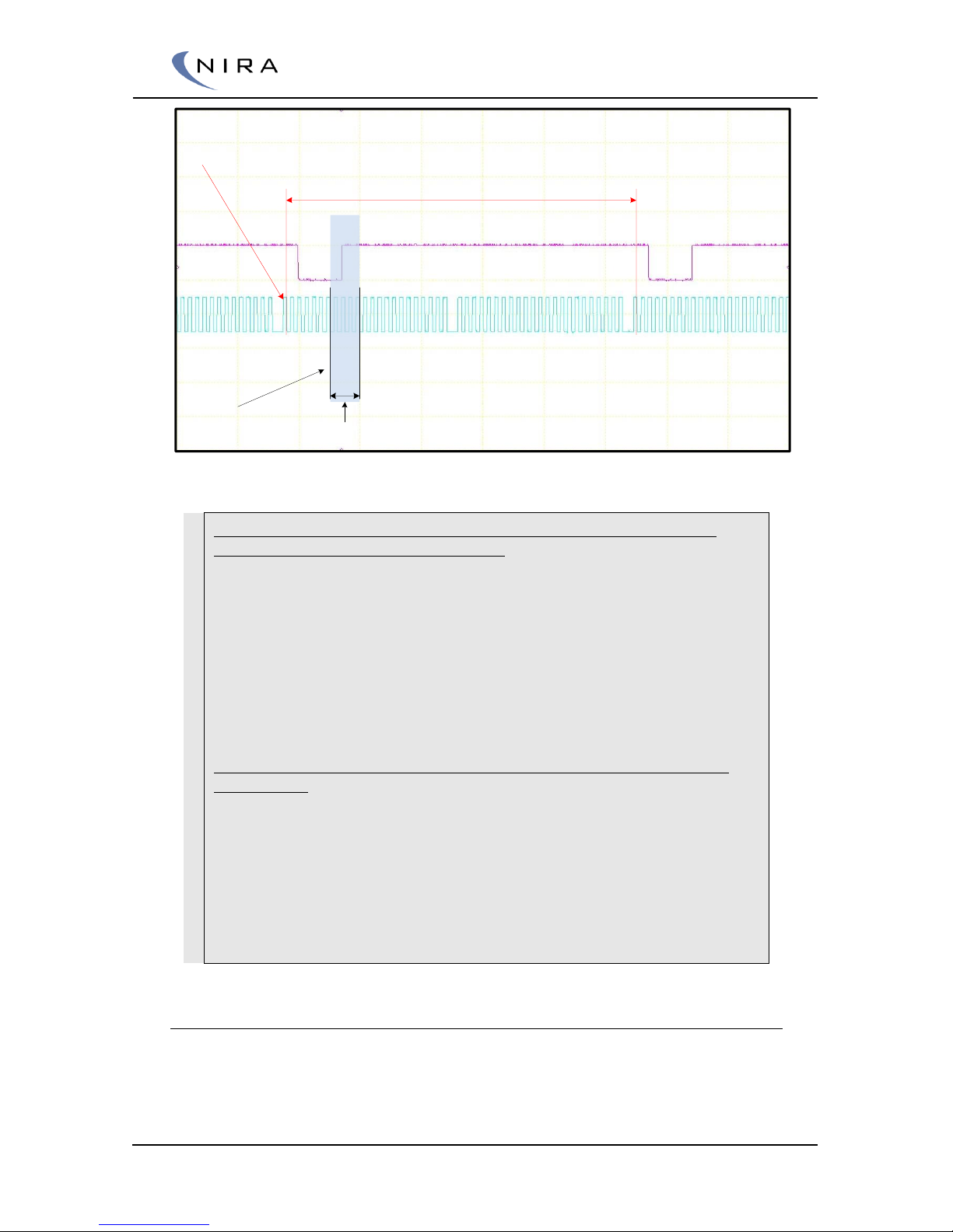
© 2005-2016 Nira Control AB 72
First teeth
Cam Window Start
Two revolutinos, 720 degrees
Cam Window Width
Scope picture of 24-1 crank wheel and a cam wheel with one tooth
Example. The picture shows a scope picture of two crank revolutions
with Hall sensors at both crank and cam.
It is a 24-1 wheel. Every tooth is 360/24 = 15 degrees/tooth
Tpu Crank Lost Teeth should be set to 1
Tpu Crank Polarity is Falling. The system looks for the first falling edge
after the lost gap. (see red vertical lines)
Tpu Crank Sensor Select should be set to Hall
Tpu Crank Total Teeth should be set to 24-1 = 23
The blue opaque field shows an area where the cam shaft sensor gives
a rising edge
Tpu Cam Sensor Select should be set to Hall
Tpu Cam Window Start correspond to teeth nr 6: 6 * 15 = 90 degrees
Tpu Cam Window With correspond to teeth nr 4: 4 * 15 = 50 degrees
Tpu Cam Polarity correspond to the cam signal transition from low to
high level within the blue field: Rising
5.1.2 Engine Setup -> Engine Specifications
Engine Specifications is related to the engine hardware. Values entered in
this section are used for air mass, fuel mass calculations and cylinder
individual timing.
Page 73
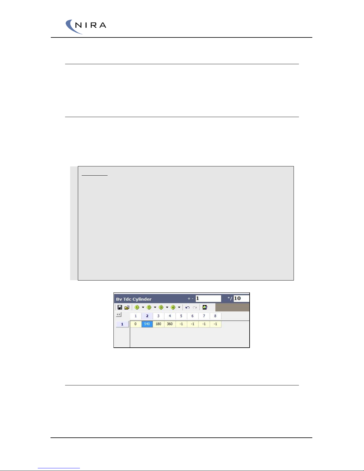
© 2005-2016 Nira Control AB 73
Bv Cylinder Volume
Swept cylinder volume for one cylinder. If your engine has 4 cylinders and a
total displacement of 2000 cm3, the cylinder volume for one cylinder is 2000
/ 4 = 500 cm3.
Bv Tdc Cylinder (firing order)
Tdc angle for each cylinder with cylinder 1 as reference. Cylinder 1 is always
zero. A cylinder that’s not in use is set to -1. This relationship is based on the
crankshaft layout and the angles between the cylinder banks if it’s a Vengine.
Example.
An in line 4 cylinder, four stroke engine with firing order 1342.
A four stroke engine needs two engine revolutions to complete all four
strokes = 720 degrees.
Inline fours usually have symmetrical spread out firing order.
The angle between TDC. 720 / 4 = 180 degrees which is the distance to
next cylinder TDC.
Cylinder 1: Always set this one to 0
Cylinder 3: 0 + 180 = 180
Cylinder 4: 180 + 180 = 360
Cylinder 2: 360 + 180 = 540
Example of TDC relationship at an 4 cyl with firing order 1342
Bv Tdc Cylinder Offset
You need to know the angle between the reference point of the pulse wheel
(“1 lost” or “2 lost”) and TDC for cylinder 1 on the trigger wheel used for the
CKP sensor. See section 3.1.2. This value needs to be entered in Engine
Setup –> Engine Specifications –> Bv Tdc Cylinder Offset. Once you have
Page 74
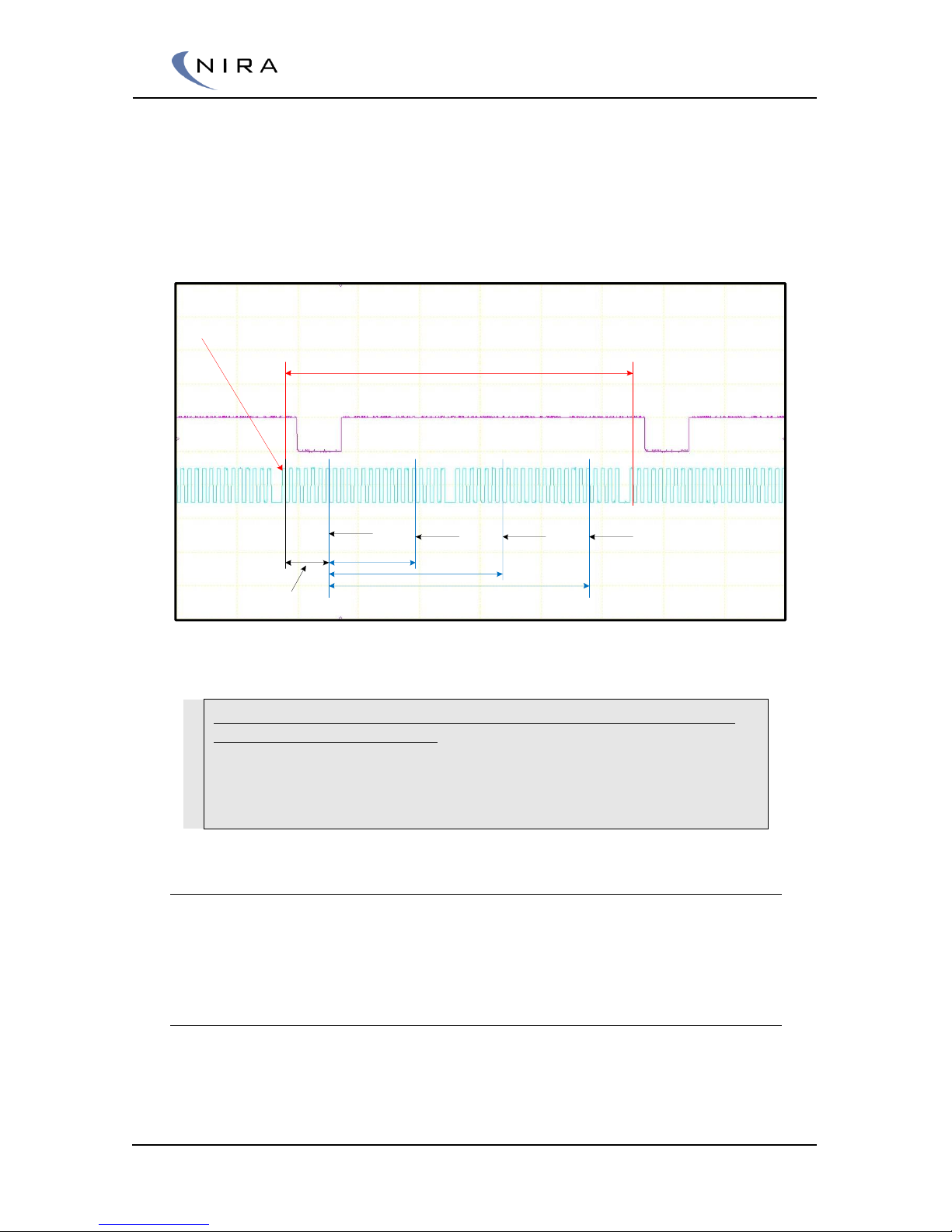
© 2005-2016 Nira Control AB 74
done this, enter a rough, basic ignition map or use the map in the default
data set that comes with NIRA rk.
The offset is a constant and rarely has any significance beyond it’s function as
a basic reference. Use a timing light and check the angle at a specific RPM
and then compare this value to Cyl 1 from 2 lost if you do not already know
what the offset is on your particular engine.
First teeth
Two revolutinos, 720 degrees
Tdc Cylinder Offset
Cyl 1 TDC
Cyl 3 TDC Cyl 4 TDC Cyl 2 TDC
Bv Tdc Cylinder
Example of a four cylinder engine with symmetrical firing order 1-3-4-2 and 90 degrees
offset to tdc at cylinder 1.
Example. The picture shows a scope picture of two crank revolutions of
an inline, four cylinder, engine.
It is a 24-1 wheel. Every tooth is 360/24 = 15 degrees/tooth
Bv Tdc Cylinder Offset. In this case the relationship between crank
wheel mounting made the offset to 90 degrees (6 teeth).
5.1.3 Engine Setup -> Fuel injectors
The fuel injector parameters are used to calculate the injector opening time
based on the requested fuel mass.
Injector offset
In NIRA rk there’s a table called Injector offset. This is the injector dead time
at different battery voltages. This table is important to adjust correctly down
to 0.1 milliseconds. The table gives NIRA i7x information about where the
Page 75

© 2005-2016 Nira Control AB 75
injector curve crosses the x-axis as well as the slope of the curve during lowload conditions
Injector offset is not the same thing as injector on-time because of the nonlinearity of the injector right after it has opened. The non-linearity is
significant for the first 2ms, which is one of the reasons mass produced
vehicles never have higher capacity injectors than absolutely necessary. (With
a higher capacity injector, the total on-time would decrease, and more of the
on-time would be spent in the non-linear territory, resulting in unpredictable
emissions etc.)
Since NIRA i7x is a fully sequential system, the on-time per injector is double
that of a system that’s not fully sequential. The result is that you can use
larger injectors and the injectors will still spend most of their time in the linear
territory.
If you are guessing as to what the injector offset values should be and you’re
off, you may notice problems with lambda drifting with the intake
temperature during low-load conditions. If the offset is far off you will have
problems starting the engine. Two tenths (0.2) of a millisecond is considered
a large error.
When using the Wizard in NIRA rk, look at the graph (F5) for “typical injector”
and you will notice how the offset changes significantly based on the injector
supply voltage (battery voltage). It’s easy to understand that 0.2 milliseconds
will result in a lambda change of several percent at idle since the total
injector on-time may only be around 2ms at idle.
As stated above, the problem is more pronounced if you are using a semi-
sequential setup. If you don’t have access to the offset values or can’t
measure them yourself, it’s recommended that you use a type of injector for
which NIRA has already determined the offset. The Wizard lists the pre-
measured injector types. Otherwise, choose ”typical injector” in the Wizard.
This gets you a base mapping you can use as a starting point for many highresistance injectors and many low-resistance injectors (using the NIRA resistor
pack mentioned above.)
Injector gain
Injector gain is the fuel injector characteristic without the offset. This value is
used to calculate the injection time based on the amount of fuel to be
injected.
NIRA i7x controls the fuel injectors based on how many milliseconds it takes
to inject exactly 1 gram of fuel with the given fuel injectors. This time is
entered in the ”Injector Gain” parameter. NIRA rk has a wizard which helps
with the calculation of injector gain.
The capacity of the injectors at a given fuel pressure and 100 % duty cycle
(i.e the injector is open all the time) and the density of the fuel. Note that
Page 76

© 2005-2016 Nira Control AB 76
some injector capacity ratings are given for 80% duty cycle and some for
100% duty cycle, often leading to confusion
The safest thing to do is to measure your particular injectors. Before
doing that, check in the NIRA rk Wizard if your injector type is available as
a “preset” type. If it is, you don’t need to measure things yourself.
In the example below the injector capacity is 400cc/minute at 3 bar pressure
using gasoline.
The density of gasoline from a retail chain such as OKQ8 is 750 kg/m3 at
15°C. You need to convert these values in order to calculate Injector Gain
because NIRA i7x needs to know the weight of the fuel being injected, not
the volume.
The weight in grams of the fuel depends on:
Fuel density. The density is different for 98 octane gasoline, racing
fuel, E85, ethanol and methanol. Even within a category the density
can be different. As an example, the different racing fuels offered
under the VP brand differ with up to 15%
The temperature of the fuel
If you expect to use a different fuel pressure than the pressure at which the
capacity was determined, an approximation is that the Injector Gain value
changes with the square root of the pressure ratio.
Example:
400 cc at 100% duty cycle and 3-bar pressure
At 4-bar pressure: sqrt(4/3) = 1,155 X 400 = 462 cc
If you use regular retail gas and the temperature of the fuel is 15°C and
the pressure is the same as when the capacity was determined and the
duty cycle is 100%, the formula for Injector Gain is trivial:
Divide 80000 into the number of cc/min. This gives Injector Gain
Example: 80000/400cc = 200 ms/g
The Wizard has additional information on this topic. Enter the value in the
Injector Gain parameter in Engine Setup in NIRA rk.
5.1.4 Engine Setup -> Fuel Specifications
Fuel specifications are used to compensate the amount of fuel based on the
fuel characteristics.
Page 77

© 2005-2016 Nira Control AB 77
Bv Fuel Density & Bv Fuel Density Corr
Bv Fuel Density gives the base value of the density in kg/L.
If fuel temperature is measured, it’s possible to compensate the fuel density
due to the temperature. The table Bv Fuel Density Corr gives a percentage
correction of the density. If the Bv Fuel Density Corr is equal to -6% the final
Fuel density is equal to Bv Fuel Density * (100 + Bv Fuel Density Corr)
Example:
Bv Fuel Density = 0,715 kg / L This value correspond to a fuel
temperature of 15 degrees Celsius.
The fuel temperature is measured to 55 degrees Celsius.
55 degrees Celsisus gives Bv Fuel Temperature Corr = -2.9%
The final fuel density used in calculations will be
0,715 * (1-0,029) = 0,694 kg / L
Fm Af Ratio (Fuel mass Air to Fuel Ratio)
Fm Af Ratio is the stoichiometric air to fuel ratio of the fuel you use.
The Air to Fuel ratio defines by “air mass” / “fuel mass”
Read more about AF, stoichiometric mixture and Lambda in Relationship
Between A/F and Lambda
Example of stoichiometric A/F ratios:
Air/98 Octane Gasoline = 14,6
Air/Methanol = 6,8
Air/Ethanol = 9,0
Air/E85 = 9,8
5.1.5 Engine Setup -> Sensors
All sensors that are necessary for engine control are found in this category.
Auxiliary sensor input is found under Mappings -> Aux Input
Page 78
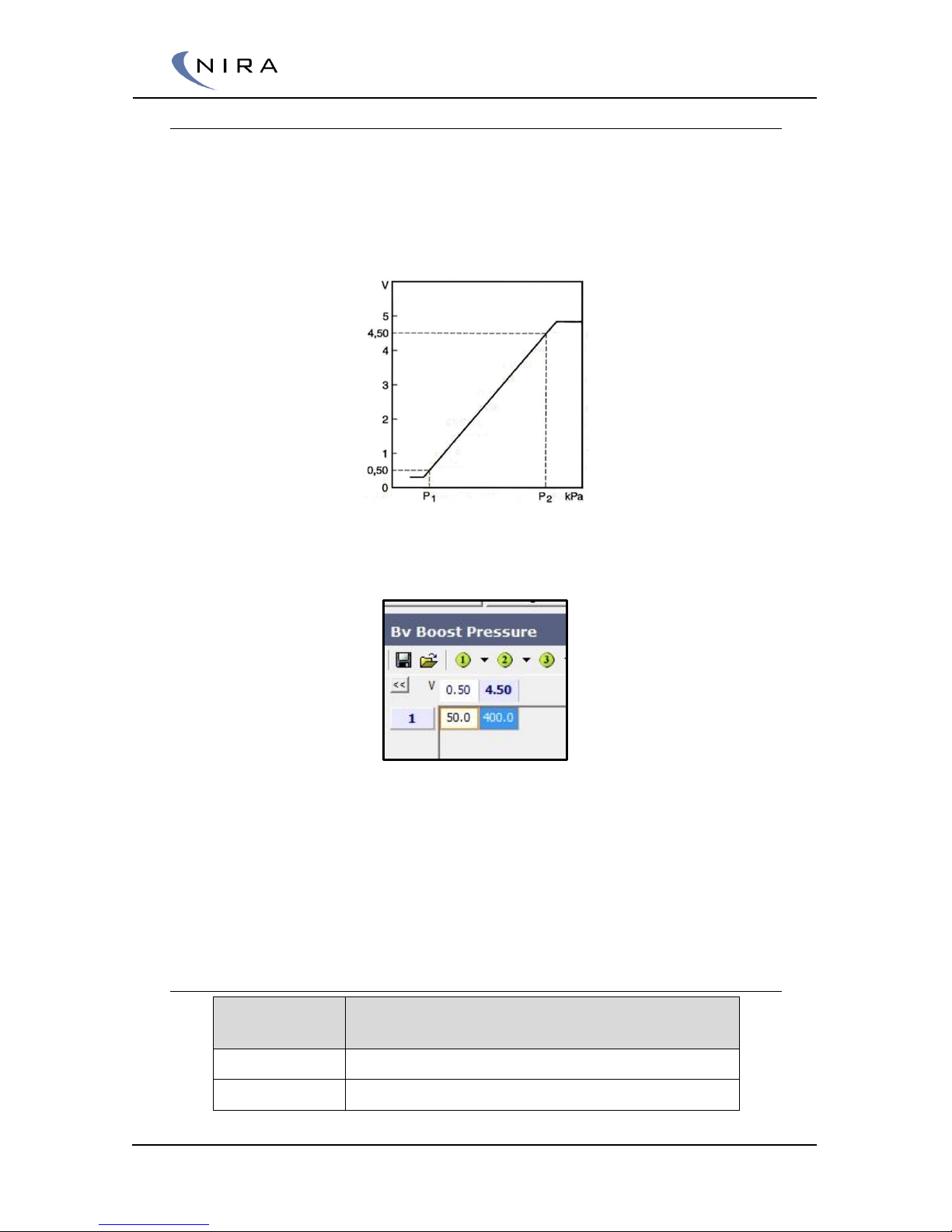
© 2005-2016 Nira Control AB 78
Pressure Sensors
Enter the minimum and maximum defined voltage in the x-axis. Enter the
corresponding pressure to the minimum respectively maximum voltage in the
table. Pressure output will be linearized for voltage measurement in between
the min and max voltage value. Note: It’s only allowed to edit axis value
while you’re offline.
Example calibration data for a pressure sensor from the sensor data sheet
P1 = 50kPa, P2 = 400kPa
Example of pressure sensor characteristic in NIRA rk
Each pressure sensors has a low pass (LP) filter possibility for smoothing out
and filtering disturbances.
The filter constant for the LP filter is named Bv XX Pressure Filter. The unit is
mS and values between 0 and 3276,7 mS are allowed.
Sensors for engine control
Pressure
Measurement
Name in Nira Rk
MAP
BV Manifold Air Pressure
Boost Pressure
Bv Boost Pressure
Page 79
© 2005-2016 Nira Control AB 79
Pressure sensors for auxiliary engine control or logging purpose
Pressure
Measurement
Name in Nira Rk
Fuel Pressure
Bv Fuel Pressure
Oil Pressure
Bv Oil Pressure
Temperature sensors
Characterize the temperature sensor by entering the correct temperature for
the given resistance.It’s possible to adapt both axis value and table value to
achieve the right sensor curve.
Note: It’s only allowed to edit axis value while you’re offline.
Example of temperature sensor characteristic
Temperature sensors for engine control
Temperature
Measurement
Name in NIRA rk
Coolant
Temperature
Bv Coolant Temperature
MAT
Bv Manifold Air Temperature
Temperature sensor for auxiliary engine control or logging purpose
Temperature
Measurement
Name in NIRA rk
Boost
Temperature
Bv Boost Temperature
Fuel
Temperature
Bv Fuel Temperature
Page 80
© 2005-2016 Nira Control AB 80
Oil
Temperature
Bv Oil Temperature
Exhaust Gas Temperature (EGT)
Three different types of EGT-sensor inputs are available.
Choose your Temperature input at:
Engine Setup -> Sensors -> Bv Exhaust Temp Source
Nira i7x handles
Temperature
Input
Name in Nira Rk
Signal Description
Digital
Bv EGT Digital
Temperature depended duty cycle of
a square wave provided by external
amplifier.
Resistive
Bv EGT Resistive
Resistance measurement of
Pt200 or Pt1000
Analog
Bv EGT Analog
0 – 5 V provided by external amplifier
Throttle or Acceleration Pedal Position (APP)
For Throttle calibration the system needs to be switched on. The procedure
is described in the Online Chapter
5.1.6 Mapping -> Fuel -> Basic
Labels related to Air- and Fuel Mass are found under the fuel map in the
Mappings tab. Prepare tables as far as possible to speed up the process.
Volumetric Efficiency Table
This is the heart of the fuel calibration. It describes the breathing of the
engine, (i.e. the volumetric fill rate of the cylinders).
Before starting you need to select load signal and set up proper axis. For
boosted engines the wizard can help you with preset tables.
Selecting load signal (Volumetric Efficiency Y-axis)
Either the MAP input (speed density calculation) or the TPS input (Alfa-N
calculation) or a combination of the two can be used as the load signal. The
Volumetric Efficiency table has a FlexiPorts™ Y-axis which makes the load
Page 81
© 2005-2016 Nira Control AB 81
signal user defined. The default Y-axis is Am Kvol Map which is the one Nira
recommends using. Am Kvol Map is the output from the Throttle to Map
table combined with the MAP sensor reading. The weight of these two inputs
is determined by the data in the Load Select Factor table as described
below.
Throttle-MAP-mix
In engine setups where an accurate MAP-reading is not possible at low loads,
the Throttle To MAP function is helpful.
Two common cases where MAP reading is not an appropriate load signal:
MAP sensor used for high boost pressure readings do not read low
pressure which is one reason of using Throttle MAP mix for accurate
low load mapping
N/A engines with high performance cam shafts do not produce low
pressure in the intake manifold.This is another reason of using throttle
to MAP mix for accurate low load mapping
The table Load Select Factor determines how much the load signal is
determined by the TPS and how much it is determined by the MAP. These
settings are made in “Advanced” mode. The values entered into Throttle to
MAP Table are used by the system as an approximation of the manifold air
pressure as a function of RPM and TPS. If the engine is run without a MAP
sensor, the engine load is entirely determined by the Throttle to Map Table.
Control the mix factor in the table.
Mapping -> Fuel ->Basic -> Load Select Factor Table
0% means that only MAP sensor reading is used.
100% means that only throttle position is used to estimate the pressure. The
estimated pressure is entered in the table below.
Mapping -> Fuel ->Basic -> Throttle to Map Table
For value in-between 0% and 100% a weighted MAP values is calculated
from the MAP sensor and from the Throttle to Map Table. The weighted
MAP value is used in the Volumetric Efficiency Table.
Calculation of MAP value used in the Volumetric Efficiency Table
The MAP value used in the Volumetric Efficiency Table will be.
AM Kvol MAP = Load Select Factor * Throttle to Map Table +
(100% - Load Select Factor ) * MAP sensor reading
Page 82
© 2005-2016 Nira Control AB 82
Example
A turbo charged engine has a MAP sensor that reads 50 -350 kPa.
The actual Manifold Air Pressure at idle is 35 kPa even though the sensor
output says 50 kPa.
By setting the Load Select Factor to 50% at small throttle angles and low
engine speed and the Throttle to Map Table to 20 kPa it’s possible to use
MAP values that are lower than the sensor reading.
The MAP value used in the Volumetric Efficiency Table will be.
AM Kvol MAP = 50% * 20 kPa + (100% - 50% ) * 50 kPa
AM Kvol MAP = 10 kPa + 25 kPa = 35kPa.
Alpha-N
It’s possible to run NIRA i7x in pure Alpha-N mode. The Volumetric Efficiency
Table has a FlexiPorts™ Y-axis which enables the user to choose the load
signal.
The FlexiPorts™ setting for the Volumetric Efficiency Table is found under.
Mapping -> Fuel ->Basic -> Volumetric Efficiency Y-axis
Click on the label to choose AM Throttle position and press enter to confirm
your choice. Note the Volumetric Efficiency Table must be closed and NIRA
rk must be offline when the Y-axis is changed. This option will change the Yaxis. Set up proper axis to make the Volumetric Efficiency table look similar to
the picture below for pure Alpha-N mode.
Example picture of a Volumetric Efficiency table with Throttle Position aa Y-axis
Page 83

© 2005-2016 Nira Control AB 83
Vol Eff Compensation Cyl 1-8
Cylinder individual Volumetric Efficiency for all cylinders. If air flow
phenomena change the air distribution in between the cylinders, the fuel
calculations should be adjusted.
With Vol Eff Compensation Cyl 1-8 it’s possible to correct VE for every
cylinder at different speed and load. Use individual lambda sensors or
exhaust gas temperature sensors to evaluate air distribution issues.
96% : VE for this cylinder is -4% related to the value in the Volumetric
Efficiency Table.
100% in these tables means no correction.
103 % VE for this cylinder is +3% related to the value in the Volumetric
Efficiency Table.
The total sum of all cylinder’s corrections should be as close to zero as
possible. If all cylinder corrections are greater or smaller than zero the
Volumetric Efficiency Table is not correctly calibrated.
Set up proper axis before going online.
The Volumetric Eff Compensation Cyl1-8 tables are equipped with Nira
FlexiPorts™.
The FlexiPorts™ settings for the Volumetric Eff Compensation Cyl1-8 tables
are found under.
Mapping -> Fuel ->Basic -> Vol Eff Comp Cyl 1-8 Y-axis.
If a pure Alpha N is used. Change the Vol Eff Comp Cyl 1-8 Y-axis to values
to AM Throttle position.
FM Lambda Target
FM Lambda target is used to calculate the fuel mass based on the air mass
filled in to the cylinder.
Set up proper axis of the Lambda target based on the Boost target. Presets
are available in the Wizard.
FM Lambda Target is equipped with Nira FlexiPorts™
Default Y-axis is AM Kvol MAP.
The FlexiPorts™ setting for the AM Kvol table is founder under.
Mapping -> Fuel ->Basic -> Flx FM Lambda Target Y.
If a pure Alpha N is used. Change the Flx FM Lambda Target Y to
AM Throttle position.
Page 84

© 2005-2016 Nira Control AB 84
5.1.7 Mapping -> Fuel -> Injection Control
Injection Stop Angle
Control the injection stop angle in this table. The angles relate to the TDC
after intake stroke.
Angles near 180 degrees are shortly before the intake valves closes.
Angles near 360 degrees are shortly after the intake valve opens.
Depending on the crank and connection rod geometry the maximum piston
speed is reached in angles smaller the 270 degrees.
Set up proper axes. Start with s small area of cells used. Expand it later or
when/if expansion is needed.
5.1.8 Mapping -> Fuel -> Acceleration
The acceleration system is built up with two imaginary acc tanks that can be
filled by quick throttle opening and drained by quick throttle closing and by
the fuel in the imaginary tanks being injected into the engine. The unit of the
acc tanks is in milligram [mg]. Therefore the amount might need adjustments
based on the engine displacement and type of fuel.
The two different acc tanks are
Fast acceleration tank will be injected during the two first rounds after
the throttle angle has been increased
Slow acceleration tank. Will be injected during a numbers of rounds
after the throttle angle has been increased
Fm Acc Enrich Enable
Enable or disable the Acceleration Enrichment with the label
FM Acc Enrich Enable
Do always start your adjustments with acceleration enrichment disabled.
Adding fuel to a tank
Only a rapid movement of the throttle should add fuel to acc tank. Both FM
Acc Slow & FM Acc Fast uses the Throttle Rate of Cange (ROC) as a
parameter in the table.
Disturbances and small changes of the throttle causes by vibrations can easily
start filling the acc tanks. To avoid this unwanted behavior, set two dead
band rows in the table where no fuel is added.
Page 85
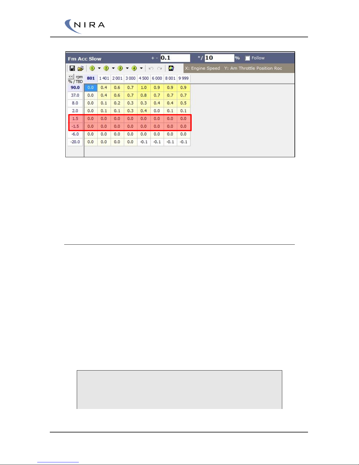
© 2005-2016 Nira Control AB 85
Example: Acceleration enrichment table with a dead band near 0 Throttle ROC.
To avoid the amount of fuel in the acc tank growing excessively there are
max and min values the acc tank can’t exceed.
The variables Fm Acc XX Tank Max & Fm Acc XX Tank Max defines the acc
tanks’ volumes.
Draining the tank
The Fast Acceleration Tank will be injected during the next two following
rounds. If the label Fm Acc Fast Cylinder Max & Fm Acc Fast Cylinder Min is
limiting the injected fuel mass the system will continue injecting during the
following rounds until the tank is empty.
The Slow Acceleration Tank will be injected in a slower manner.
The table Fm Acc Slow Factor controls the amount of the slow tank to be
injected. The Fm Acc Slow factor percentage value will control the injected
slow mass based on the actual acc tank value. This continues until the tank is
empty.
The injected fuel mass can’t exceed the Fm Acc Slow Cylinder Max & Fm Acc
Slow Cylinder Min
Example:
From the table FM Acc Slow, 30mg of fuel have been added to Slow
acc tank.
Page 86
© 2005-2016 Nira Control AB 86
The Fm Acc Slow Factor is mapped to 5%.
The extra amount of fuel to be injected next to rounds caused med
slow acceleration enrichment will be:
30mg * 5% = 1,5 mg
The following two rounds
(30-1,5)mg * 5% = 28,5mg * 5% = 1,425 mg will be injected.
5.1.9 Mapping -> Engine Start
A number of tables are used for control the pre start, start and post start
enrichment.
Start choke
Start Choke table is used for control the fuel during engine warm up.
0% = No Enrichment
20% = 20% More fuel
Post Start Enrichment
The maximum Post start enrichment is controlled in the table
Start Enrichment. The total enrichment for post start can never be greater
than this value.
Start factor. The start factor is the percentage value of the start enrichment to
be used. The start factor shall be ramped down to zero when the numbers of
total revolutions increase.
The table Start Index has Time between start at one axis and start revolution
at the other axis. The output is start index used in the table.
Start Primer
In the beginning of the start sequence, an additional fuel squirt is added. This
additional fuel is injected as soon as NIRA i7x is synchronized. The
appropriate amount of fuel depends on the engine temperature and is
programmed in Start Primer Table. The amount of fuel is given in mg per
cylinder and the Start Primer Table is independent from Start Sequence
Enrichment Table.
Page 87

© 2005-2016 Nira Control AB 87
5.1.10 Mapping -> Ignition
Ignition timing table is default set up with MAP reading at it Y-axis. It’s
possible to change the Y-axis of the ignition timing table by the label:
Mapping -> Ignition -> Flx Ign Angle Base Y
If Throttle based ignition angles are choosed, make sure the same axis is
used in the Volumetric Efficiency Table.
For turbo or super charged engines a couple of preset tables are available in
the Wizard. All provided preset tables should only be used for setting proper
axis values and for start up purposes. Make sure that the ignition timing is
correctly calibrated for your engine before putting load on the engine.
Consult your NIRA i7x dealer for help with the calibration.
Ignition timing is an area of great interest and where a proper calibration can
yield significant power improvements.
It’s very important, however, to make sure the ignition timing is correct since
too much advance can cause significant damage at high loads. The damage
occurs when premature detonation (or knock) happens. Knock is when the
combustion happens too fast and the air-fuel mixture explodes instead of
burning in a controlled fashion.
Knocking results in very high temperatures in the combustion chamber and it
can sometimes chip the surface of the piston. More commonly, though, it can
melt the edges of the piston.
You have to learn how to listen to your engine and hear knocking before you
start modifying the ignition timing.
Advancing the timing increases the efficiency of the engine and lowers the
fuel consumption and yields more engine power. You have to understand
how boost pressure, compression, MAT, the gasoline octane rating, rpm,
air/fuel mixture, load conditions etc. all effect the max ignition advance
before you start modifying the timing.
You can check the ignition timing by entering the same value in the entire
table. Choose a value around 20 degrees of advance. Then connect a timing
light to cylinder 1 to verify that you see the correct advance at the crank
pulley. Naturally, this requires that the pulley has the appropriate markings.
Most engines run well with 20-30 degrees advance in the entire table up to
100 kPa MAP.
It’s beyond the scope of this manual to give any further advice on how to
calibrate ignition timing.
Ignition MAT Compensation
Engines are more knock resistant when the intake air is cooled down.
Compensate the ignition for Manifold Air Temperature in this table.
Page 88
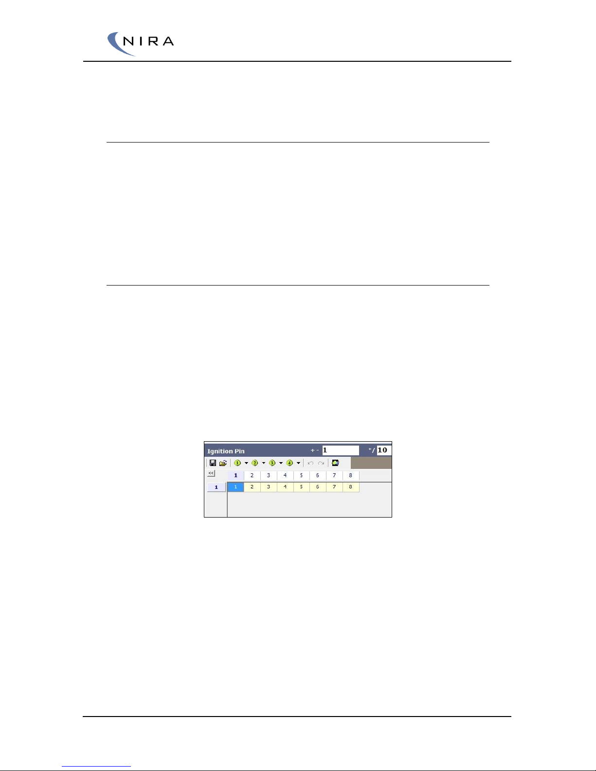
© 2005-2016 Nira Control AB 88
Negative value means retarded ignition
Positive values means advanced ignition
Ignition Flexiport Comp
Ignition Flexiport Comp is a totally user defined ignition compensation. The
table is equipped with Nira FlexiportTM at both X- and Y-axis.
The table could be used four nitrous compensation or water injection
compensation.
Negative value means retarded ignition
Positive values means advanced ignition
Ignition pin
NIRA i7x is equipped with 8 ignition outputs. The table Ignition Pin controls
which output is used for a certain cylinder.
Note: This should be an Offline change. Do Not change due to the firing
order in this table. Firing order is set up in “Bv Tdc Cylinder”.
One Coil per Cylinder (COP & CPP)
For sequential setup with up to 8 cylinder individual coils, one ignition output
should be related to one coil.
Ignition Pin configuration for cylinder individual coils. One ignition output for each cylinder.
Waste fire Coil
It is possible to control a waste fire coil even though the injection is
sequential.
Page 89
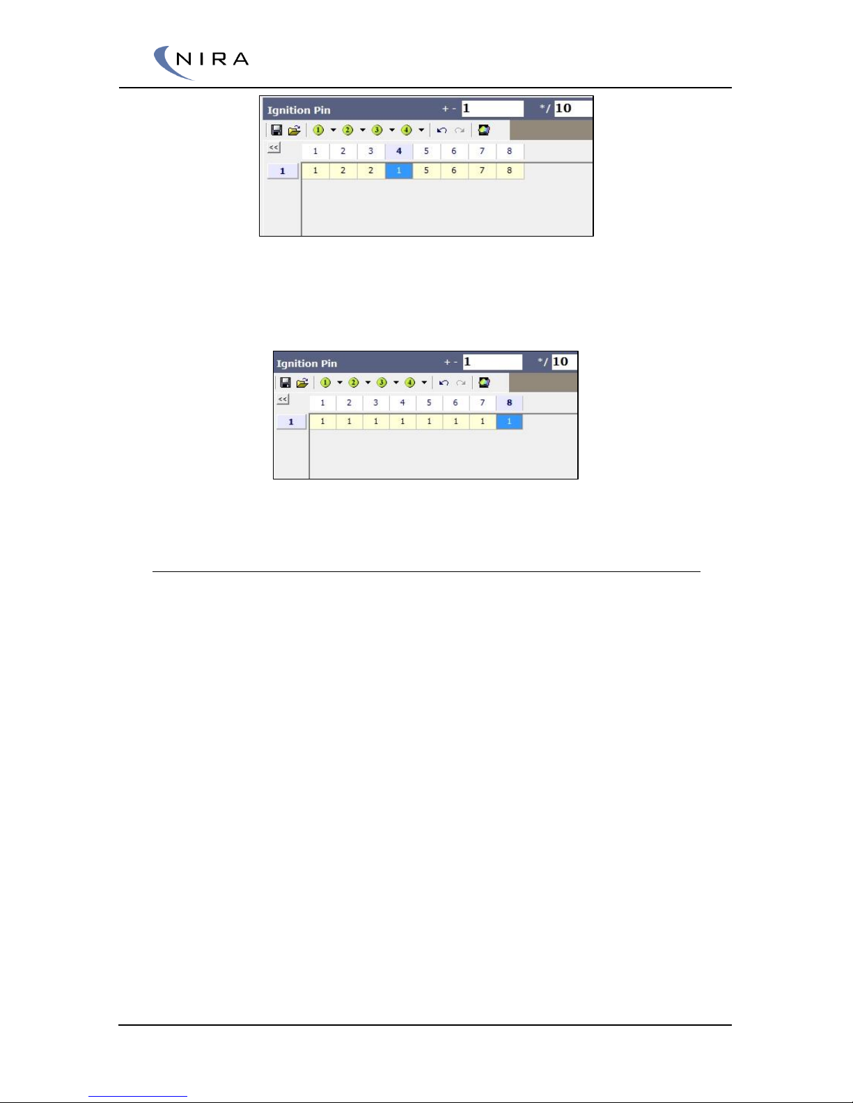
© 2005-2016 Nira Control AB 89
Ignition Pin setup for controlling a waste fire coil on a 4 cylinder engine
Distributor
If distributor is used, all ignition outputs should be set up to the same output.
Ignition pin setup for distributor set up
5.1.11 Mapping -> RPM Control -> RPM Limit
The rpm limit cuts out either injection or ignition to prevent over revving. For
emission control injection cut outs are preferred.
Engine Speed Limit is where the RPM limit starts to cut out injection or
ignition. The cut rate at Engine Speed limit is controlled in Es Limit Cut
level Min
Es Limit Cut Level Min is the cut rate that is used when enter Engine
speed limit
Engine speed Limit Range When passing Engine Speed Limit +
Engine Speed Limit Range the cut rate is 100%. In the rpm range the
cut rate is linearized between Es Limit Cut level Min and 100%
Es Limit Cut Injection decides if injection or ignition should be cut out
Page 90
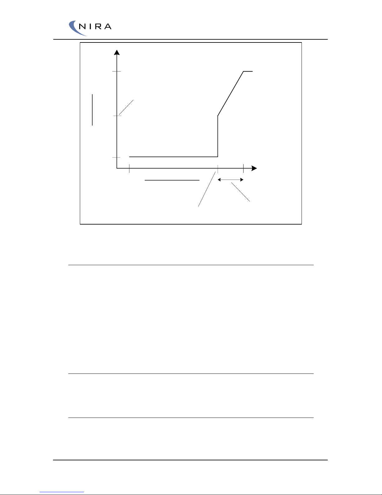
© 2005-2016 Nira Control AB 90
Engine Speed [rpm]
Cut out [%]
0 %
100 %
0
Engine Speed limit
Engine Speed limit range
ES Limit Cut Min
Explanation of the Engine Speed Limit
5.1.12 Mapping -> RPM Control -> RPM Control
The idle speed is calibrated by adjusting the parameters found in the “Air
RPM” and “Ignition RPM” folders respectively. The parameters in the “Air
RPM” folder are used for adjustment of an IAC valve or similar actuator that
controls the airflow. The parameters in the “Ignition RPM” folder are
adjusted to enable a stable idle control by altering the ignition.
Fine-tuning of the idle speed is ideally done by altering the ignition since the
technique of controlling air flow has inherent characteristics that makes it
more suitable for rough adjustments.
5.1.13 Mapping -> AUX -> Input
Ten auxiliary inputs are available in NIRA i7x.
Aux Analog Input
Two analog inputs, typically used for ratiometric 0-5 V sensors such as
additional pressure sensors can be utilized as auxiliary inputs. These are
configured using the tables Bv Aux Ainput1 and Bv Aux Ainput2 respectively.
Page 91
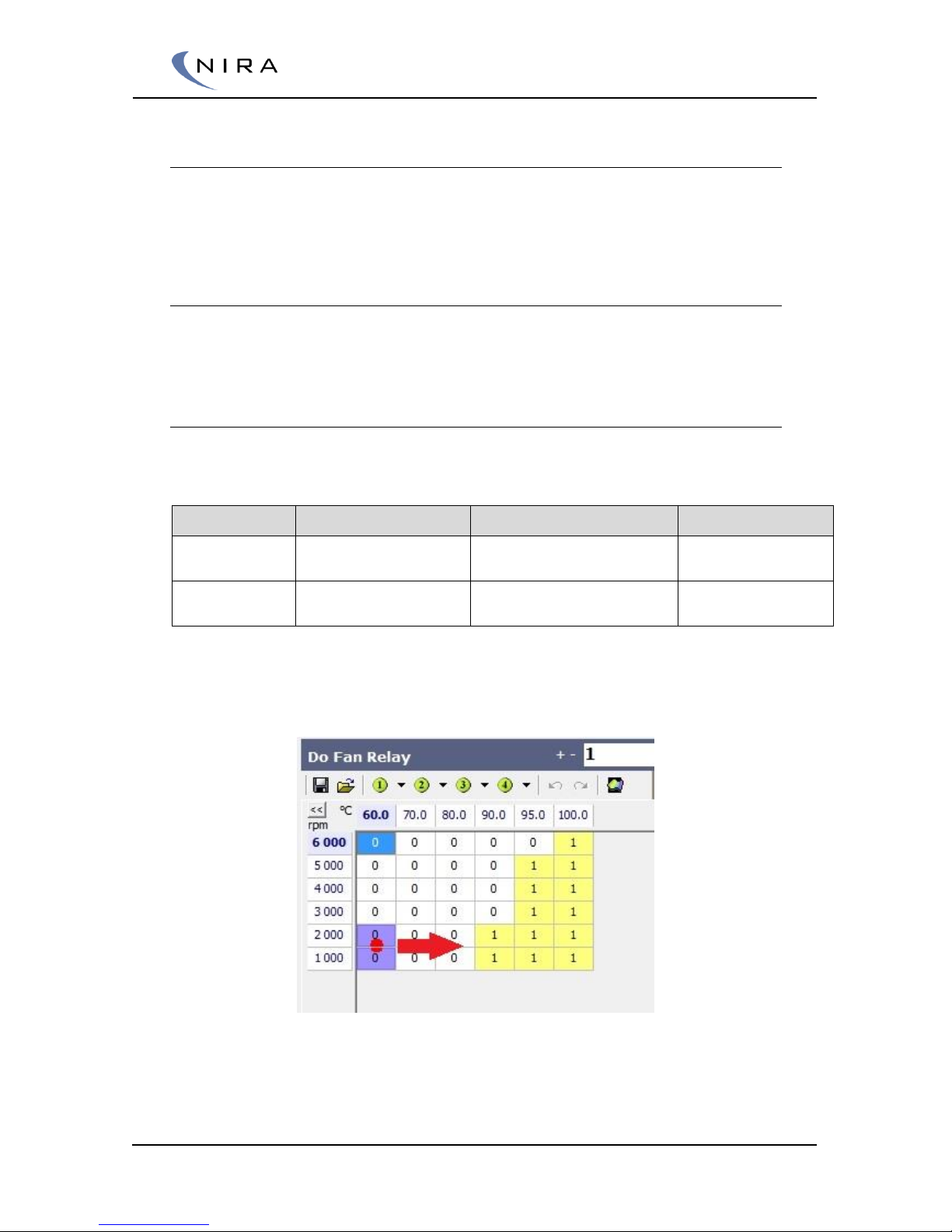
© 2005-2016 Nira Control AB 91
Aux Temp
Six temperature inputs, typically used for NTC/PTC type temperature sensors
can be utilized as auxiliary inputs. These are configured using Bv Aux TempX,
where x is an integer between 1 and 6.
Aux Digital Input
Two inputs are available for detection of pulse signals, e.g. from wheel speed
sensors. These are configured in Di Aux1 Teeth and Di Aux2 Teeth.
5.1.14 Mapping -> AUX -> Output -> Relay Control
NIRA i7x provides two fully customable relay controls.
Name
Controlled by
Comment
Related pin
Do Fan Relay
2D matrix with user
defined axis
The output pin is active low
V55, Fan RLY
Do Aux Relay
2D matrix with user
defined axis
The output pin is active low
V38, Aux RLY
Relay Control uses hysteresis. The Relay Control only switches when the
matrix output is one or zero.
The red arrow shows direction of movement in Fan relay matrix when Coolant temp
increases
Page 92
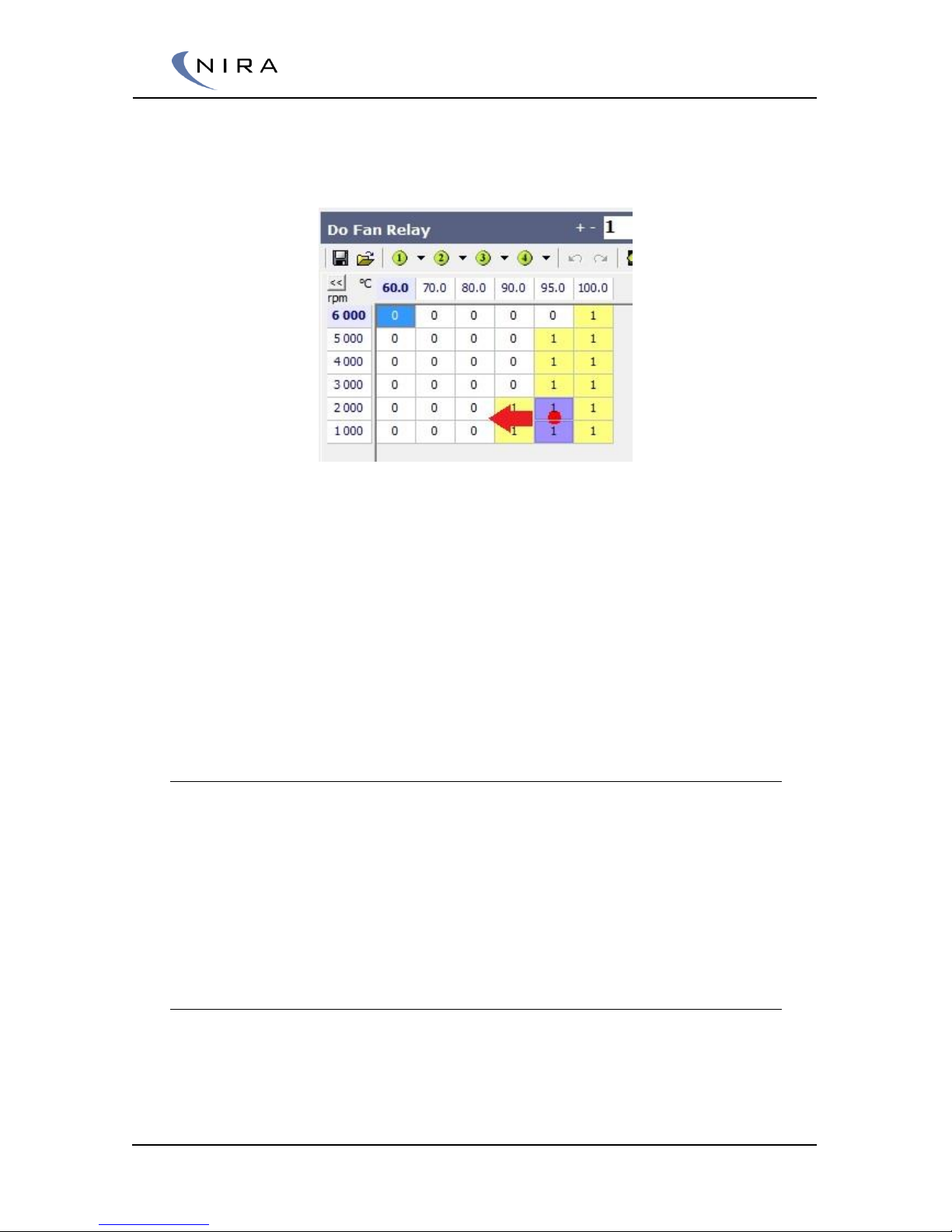
© 2005-2016 Nira Control AB 92
To activate the relay output, the output from the matrix has to reach 1. In the
example matrix above, the coolant temperature has to reach a temperature
higher than 90 degrees Celsius to enable relay activation.
The red arrow shows direction of movement in Fan relay matrix when Coolant temp
decreases.
For deactivation the matrix has to reach an output equal to zero. In the
example matrix above, the relay output will stay active until the temperature
reaches a value lower than 80 degreases Celsius.
Between 80 and 90 degrees the output from the matrix will be in between
one and zero and the output will not be affected.
Change the values in the matrix axis to achieve a more narrowband
hysteresis.
DO Aux Relay
The matrix Do Aux Relay has user defined X- and Y-axis. It’s possible to
choose between a wide range of values in NIRA i7x to tailoring your own
control behavior.
The labels for axis control are:
Flx Do Aux Relay X
Flx Do Aux Relay Y
5.1.15 Mapping -> AUX -> Output -> PWM Control
NIRA i7x provides three fully customable PWM controls with different
characteristics.
Page 93
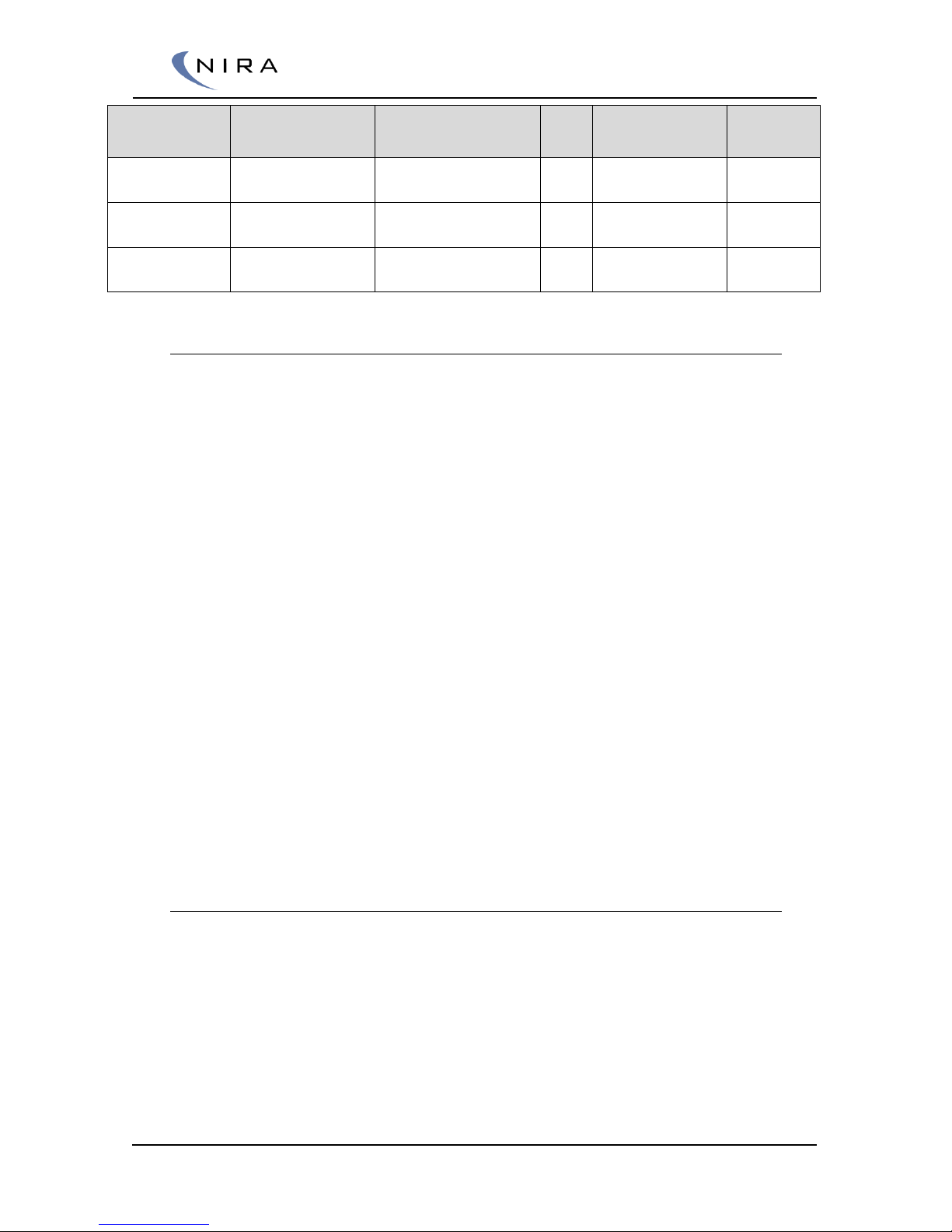
© 2005-2016 Nira Control AB 93
Name
Controlled by
Characteristics
Comment
Related
pin
Do Aux PWM1
3D matrix with user
defined axis
6 amp for low speed
inductive load
Low sider driver
E83, Aux
PWM1
Do Aux PWM2
3D matrix with user
defined axis
2 amp for low speed
inductive load
Low sider driver
V90, Aux
PWM2
Do Aux PWM3
3D matrix with user
defined axis
2 amp for high speed
inductive load
Low sider driver
V56, Aux
PWM3
Do Aux PWM-x labels
All three Do Aux PWM-x is set up the same way.
Do Aux PWM-x period
The period time of the PWM signal
Do Aux PWM-x duty
A 3D matrix with the base duty
Do Aux PWM-x duty out
The output from the matrix Do Aux PWM-x duty table is the input to
this matrix. The Aux PWM-x duty out table handles non linear behavior
of actuators.
Flx Do Aux PWM-x duty X
User defined X-axis of the matrix
Flx Do Aux PWM-x duty Y
User defined Y-axis of the matrix
Flx Do Aux PWM-x duty Z
User defined Z-axis of the matrix
5.2 Going Online
When you have entered values for all parameters in Engine Setup you can
connect your PC to NIRA i7x. Follow the steps below before you attempt to
start the engine.
1. Turn on the ignition
Page 94
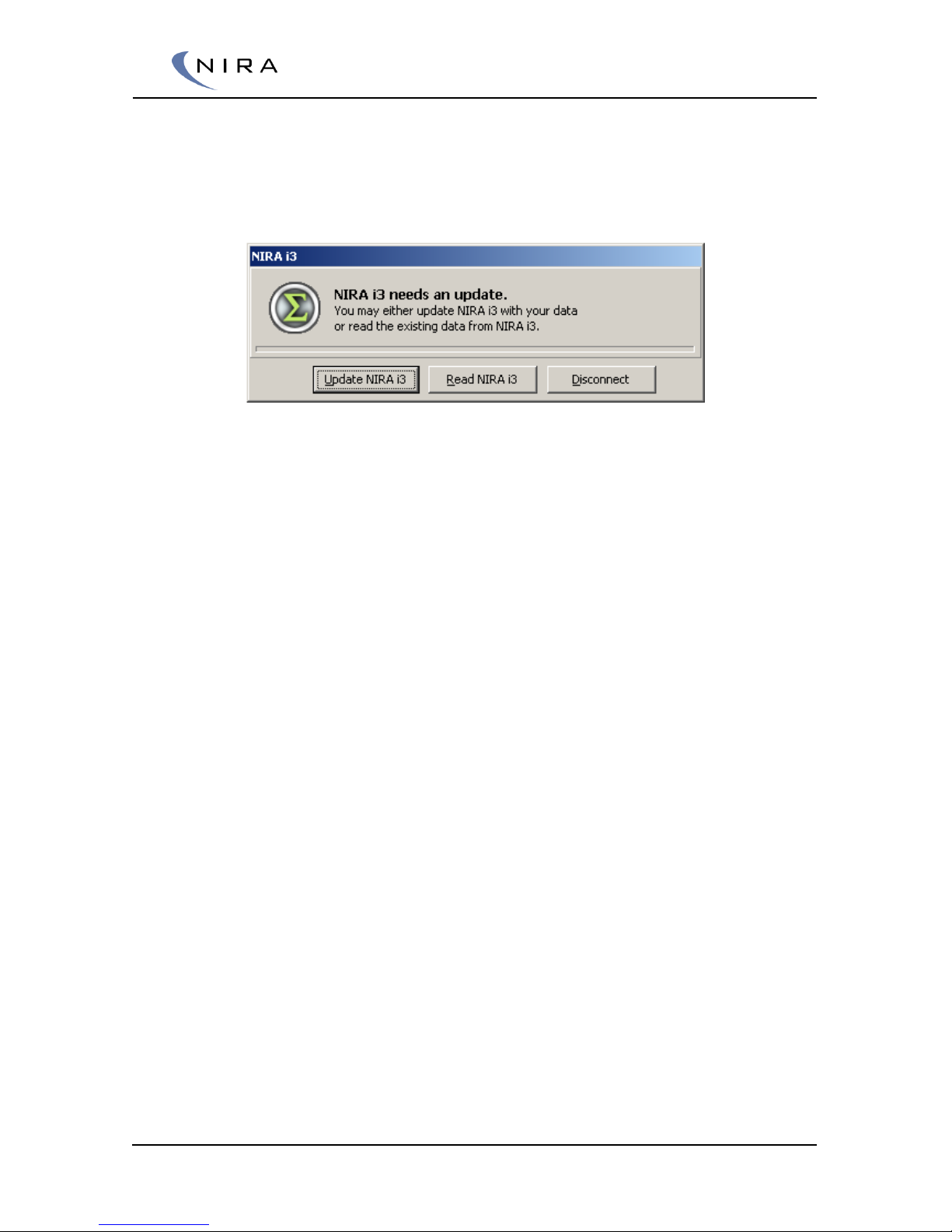
© 2005-2016 Nira Control AB 94
2. At the top of the main window in NIRA rk is the online/offline status
bar. In order to go online, click on the little green flash icon in the top
left corner of the main window in NIRA rk. If the parameters in NIRA rk
are different from the parameters previously uploaded to NIRA i7x,
you will see the following dialogbox:
3. Select Update NIRA i7x in order to upload all the data to NIRA i7x.
This may take as long as two minutes.
Later you can select Read NIRA i7x if you want to download all the
settings from NIRA i7x into NIRA rk so you can save them as an i3d
file. (This is very handy if, for some reason, your PC were to hang while
you’re in the middle of calibrating the engine since you can always go
back and download the most recently used calibration.)
4. Once you have uploaded the data to NIRA i7x, the system goes
online, the status bar changes colors to green and the text changes to
Online.
5. When the system is in the Online mode, it’s important to first go to the
Mappings tab and select the Monitor Output folder in the tree to the
left and then select Alarm. Doing this allows NIRA i7x to detect
different errors and set alarms. If it doesn’t say OK next to all
parameters then the values in Engine Setup are wrong or the
sensor/actuator installation is wrong. Any alarm that’s viewable via the
Alarm folder is also displayed as large icons above the main tabs.
These icons will disappear once the cause of the alarms has been
corrected.
Page 95
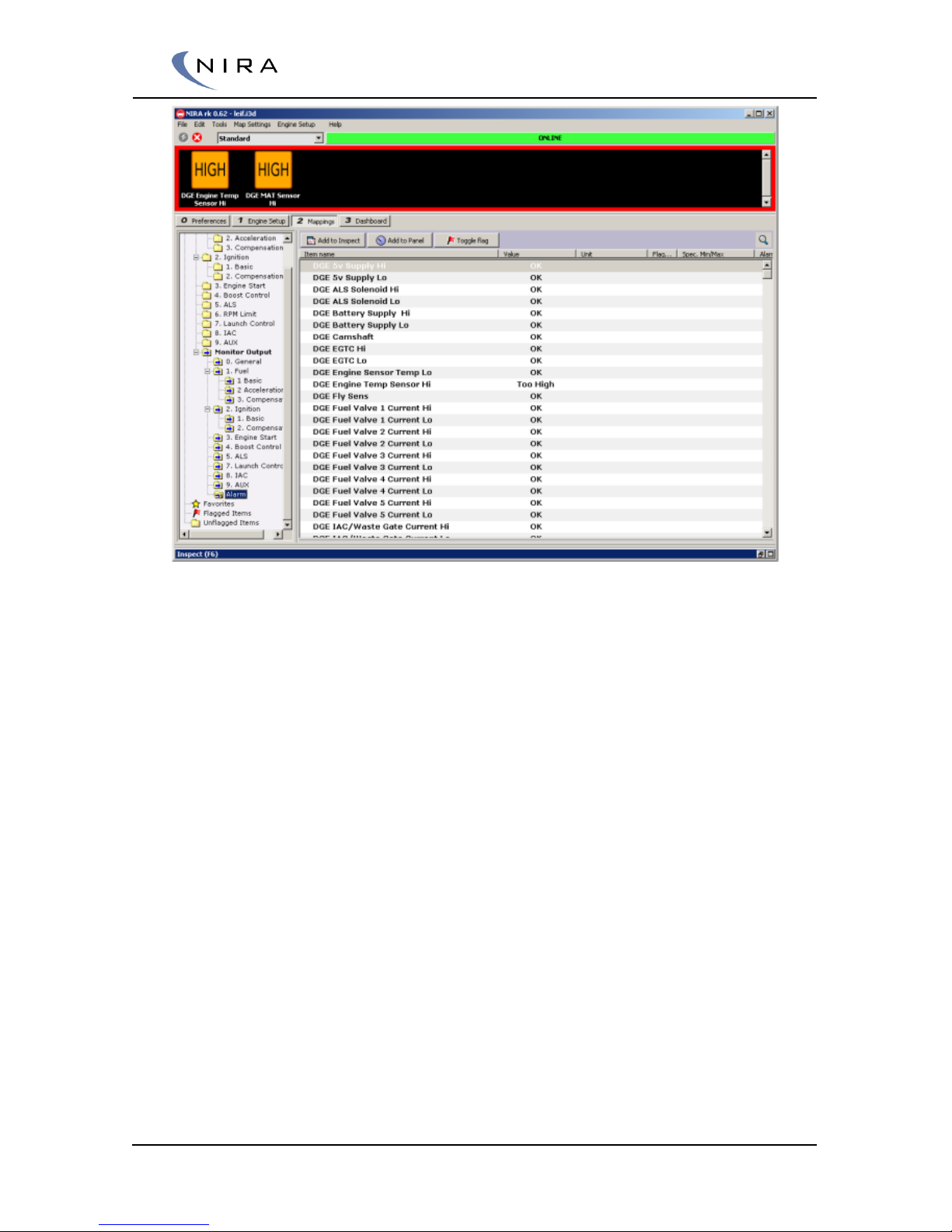
© 2005-2016 Nira Control AB 95
6. Calibrate the Throttle Sensor such that the parameter reads 0% when
you take your foot off the gas pedal and 100% when you depress the
pedal fully. This can be done with the help of the “Accelerator
Calibration Wizard” in NIRA rk. If you want to calibrate the Throttle
Sensor manually, follow the steps below.
Set NIRA rk to advanced mode.
Look for the labels.
Engine Setup -> All Paramters-> App Ad Pot 1 & App Ad Pot 2
Make a note of the parameter values for App Ad Pot 1 & App Ad Pot
2 when the gas pedal is fully depressed and when you let go of the
pedal completely.
The notes should for App Ad Pot 1 & 2 for fully depressed throttle
should be transferred to
Engine Setup -> Sensors-> App Pot 1 Umsp & App Pot 2 Umsp
Make the corresponding transfer from notes for fully released throttle.
Enter the values in
Engine Setup -> Sensors-> App Pot 1 Umsp & App Pot 2 Umsp
Do Key Off & Key on.
Check Engine Setup -> All Paramters-> App Position
Page 96
© 2005-2016 Nira Control AB 96
Example. (Make sure the Throttle is fully closed before you start)
When the throttle is fully opened.
App Ad Pot 1 = 87,3%
App Ad Pot 2 = 0,1%
When the throttle position is fully closed.
App Ad Pot 1 = 7,4%
App Ad Pot 2 = 0,1%
Enter following values
App Pot 1 Umsp = 87,3%
App Pot 2 Umsp = 0,1%
App Pot 1 Lmsp = 7,4%
App Pot 2 Lmsp = 0,1%
Switch the key off and then on again and check.
Engine Setup -> All Paramters-> App Position
The value should go from 0% to 100 % when opening the throttle.
Now the throttle sensor is calibrated.
7. Go back to the Mappings tab, select the Monitor Output folder and
the ”General” subfolder. Make sure all sensors are calibrated
correctly. If they are not, return to the Engine Setup tab, select the
Sensors folder and correct the problem.
ECT and MAT sensor values should show ambient temp, or else
they’re calibrated wrongly.
MAP should say approximately 100kPa, which is ambient pressure.
You can now start the engine. Select Toggle Dashboard under the Tools
menu in the main menu, or hit the F7 key. Crank the engine. You should see
the tach needle jump up to about 200 rpm or else the CKP sensor signal is
missing and you won’t be able to start the engine.
Your engine should start fairly quickly and show reasonable values on the
dash. If any instrument is showing an unreasonable value or if an Alarm icon
appears, something is wrong in one of the parameters in Engine Setup, or
the electrical installation is problematic.
Since the IAC hasn’t been calibrated yet, you may have to give a bit of gas in
order to keep the engine from stalling.
Page 97
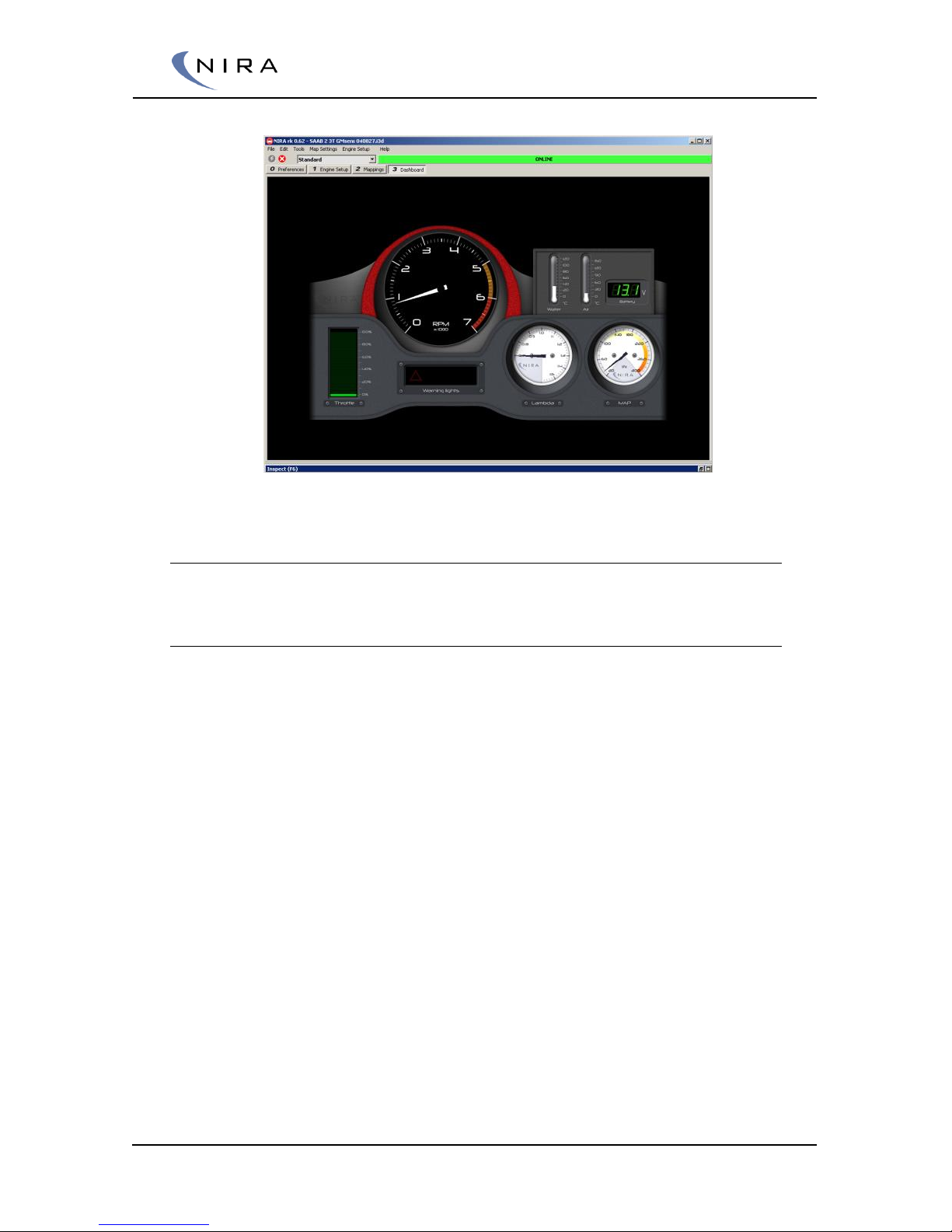
© 2005-2016 Nira Control AB 97
5.3 Quick Troubleshooting Guide
5.3.1 The Engine Won’t Start
Some of the more common causes are:
Missing CKP sensor signal. Verify that the tachometer shows
approximately 200rpm when you crank the engine. If not, then the
CKP sensor installation is the cause. Analysis of the CKP sensor signal
is done using an oscilloscope
Lack of fuel. Verify that the fuel pump is running. The pump should
run for about 2 seconds every time the ignition key is turned to the
Key On Engine Off position (KOEO) position if the fuel pump and fuel
pump relay are connected correctly. The pump also runs whenever
the engine cranks and NIRA i7x sees a correct signal from the CKP
sensor
No current to the fuel injectors. Check that the injectors are getting
pulsed properly. If not, the electrical connections to the injectors are
wrong or the injector setup in Engine Setup is wrong. Normal injector
current is 0.8A for a 14 Ohm injector.
DGE Camshaft alarm. If this alarm is set the CMP sensor signal is
wrong. Either the electrical connection is wrong or the setup in
Engine Setup is wrong. (NIRA i7x may still be able to sync things
correctly and start the engine approximately half the time.)
Page 98

© 2005-2016 Nira Control AB 98
Wrong MAP. Verify that the MAP sensor reading is around 100kPa
(ambient pressure) when the starter isn’t turning. The MAP parameter
is under “Mappings”-> Monitor Output -> 0.General -> Bv Manifold
Air Pressure. If you see a different pressure reading, the calibration is
wrong or the sensor is damaged.
5.4 Other Adjustments
Since you were able to start the engine you are now ready to begin adjusting
parameter values in order to improve engine performance. The next chapter
includes lots of advice on how to do this.
Page 99

© 2005-2016 Nira Control AB 99
6
Mapping your Engine Using
NIRA rk
NIRA rk has two different modes; Standard and Advanced. The Standard
mode is sufficient to achieve excellent mapping results. The Advanced mode
gives access to a set of additional mapping parameters, which normally never
need to be adjusted.
6.1 Tables
Don’t set up too many RPM columns on the x-axes in the beginning.
Keeping the number low simplifies the calibration effort. It’s very easy to add
columns later if you need greater resolution. The same is true for the y-axes.
You can eliminate the impact of any row or column by setting its value to an
out-of-range value, e.g. 10,000 rpm or 0kPa.
The scale of the x and y axes is fully adjustable, which is a very powerful
feature. This lets you increase resolution significantly in sensitive areas by
adding more calibration points.
6.2 Calibrating Ignition
As described earlier, calibrating ignition is a delicate matter. A thorough
understanding of the engine’s allowed peak cylinder pressure, about knock
and about how ignition timing affects the combustion is crucial to achieve a
good ignition calibration. Delving into these matters is beyond the scope of
this handbook.
Page 100

© 2005-2016 Nira Control AB 100
6.2.1 Ignition at Idle
Ignition during engine idling is calibrated using the parameters available in
the RPM Control RPM Control Ignition RPM folder.
6.3 Calibrating Fuel
NIRA i7x controls the amount of injected fuel based on two tables;
Volumetric Efficiency Table (VE) and Fm Lambda Target. In NIRA rk, you find
these tables in the Mappings tab under All Parameters -> 1.Fuel -> 1.Basic
Calibrate these tables by following the steps below.
6.3.1 Engine Start Fuel
For the engine to start, the correct amount of fuel has to be injected. The
settings for start fuel are adjusted in the tables found under Engine Start
Injection control. How much extra fuel that is needed depends on a number
of parameters and varies from engine to engine. Start with the default values
and iterate changes until you are happy with the result.
In the beginning of the start sequence, an additional fuel squirt is added. This
additional fuel is injected from all injectors at the same time, as soon as NIRA
i7x detects crankshaft rotation. The appropriate amount of fuel depends on
the engine temperature and is programmed in Start Primer table. The
amount of fuel is given in mg per cylinder and the Start Primer table is
independent from the values in the Choke Enrichment table and the other
tables in the Engine Start folder.
6.3.2 Volumetric Efficiency Comp Table
This table sets up the compensation table for VE as a function of MAT.
When the MAT increases, the intake air volume expands, which in turn means
the engine requires less fuel. Using the ideal-gas equation, we get
k=273/(MAT+273)
where the MAT is given in degrees Kelvin (K). 273K = 0°C.
When the fuel is injected and vaporized in the intake manifold, it cools the
intake air, which increases VE. In addition, the cooling effect increases with
MAT.
Based on experiments, a good approximation, when using gasoline, is the
square root of k, which gives the final formula for VE compensation as:
 Loading...