

Page 1

MAGNETIC PRINTER
22 A1 13NS REV5
VARYPRESS 200
Site preparation guide
Page 2

Page 3

MAGNETIC PRINTER
NIPSON SAS
28, rue E. Thierry-Mieg - BP 257 - 90005 Belfort Cedex - France
Tel.: +33 (0)3 84 54 50 00 - Fax: +33 (0)3 84 54 52 18
http:/www.nipson.com - e-mail: info@nipson.com
VARYPRESS 200
Site preparation guide
MATERIEL
Document release:
REV0 July 2004. Creation.
REV1 Jan. 2006. Update with 90 m/min and operating conditions.
REV2 Jan. 2007. Information added about UPS.
REV3 July 2007. Update information about connection to the network.
REV4 Oct. 2007. Update operating conditions.
REV5 Fev. 2008 Update with pressure and ground loading/unit added.
22 A1 13NS REV5
Page 4

© NIPSON 2004
All rights reserved
We will be pleased to receive any suggestions concerning the form and content of this manual.
A sheet on which to write your remarks is provided at the end of this manual.
This document is for information purposes only. NIPSON cannot be held responsible for any damage caused by applying
instructions contained within it. Corrections or modifications to the content of this document may be made without notice;
they may be communicated to recipients in later updates.
22 A1 13NS REV5
ii
Page 5

Site preparation manual
VARYPRESS 200
Table of contents
1. GENERALITIES . . . . . . . . . . . . . . . . . . . . . . . . . . . . . . . . . . . . . . . . . . . . . . . . . . . . . . . . . . . . . . 1-1
1.1 CHARACTERISTICS OF THE PRINTER . . . . . . . . . . . . . . . . . . . . . . . . . . . . . . . . . . . . . . . . . . . 1-1
1.2 MACHINE PACKING . . . . . . . . . . . . . . . . . . . . . . . . . . . . . . . . . . . . . . . . . . . . . . . . . . . . . . . . . . 1-2
1.3 TEMPERATURE AND HUMIDITY REQUIREMENTS . . . . . . . . . . . . . . . . . . . . . . . . . . . . . . . . . . 1-3
1.4 AIR CONDITIONING . . . . . . . . . . . . . . . . . . . . . . . . . . . . . . . . . . . . . . . . . . . . . . . . . . . . . . . . . . . 1-4
1.5 PAPER STORAGE. . . . . . . . . . . . . . . . . . . . . . . . . . . . . . . . . . . . . . . . . . . . . . . . . . . . . . . . . . . . . 1-5
1.6 TONER STORAGE . . . . . . . . . . . . . . . . . . . . . . . . . . . . . . . . . . . . . . . . . . . . . . . . . . . . . . . . . . . . 1-5
1.7 CLEANING . . . . . . . . . . . . . . . . . . . . . . . . . . . . . . . . . . . . . . . . . . . . . . . . . . . . . . . . . . . . . . . . . . . 1-6
1.7.1 Cleaning of the printer . . . . . . . . . . . . . . . . . . . . . . . . . . . . . . . . . . . . . . . . . . . . . . . . . . . . . . . . . 1-6
1.7.2 Cleaning of the room - dust accumulation. . . . . . . . . . . . . . . . . . . . . . . . . . . . . . . . . . . . . . . . . 1-6
1.8 SPECIFIC TOOL FOR INSTALLATION . . . . . . . . . . . . . . . . . . . . . . . . . . . . . . . . . . . . . . . . . . . . 1-7
2. SITE REQUIREMENTS . . . . . . . . . . . . . . . . . . . . . . . . . . . . . . . . . . . . . . . . . . . . . . . . . . . . . . . . . 2-1
2.1 INTRODUCTION . . . . . . . . . . . . . . . . . . . . . . . . . . . . . . . . . . . . . . . . . . . . . . . . . . . . . . . . . . . . . . 2-1
2.2 PRINTER PHYSICAL SPECIFICATIONS . . . . . . . . . . . . . . . . . . . . . . . . . . . . . . . . . . . . . . . . . . . 2-1
2.2.1 Printer dimensions . . . . . . . . . . . . . . . . . . . . . . . . . . . . . . . . . . . . . . . . . . . . . . . . . . . . . . . . . . . . 2-1
2.2.2 Air conditioning unit for write heads . . . . . . . . . . . . . . . . . . . . . . . . . . . . . . . . . . . . . . . . . . . . . 2-6
2.2.3 Floor space requirements . . . . . . . . . . . . . . . . . . . . . . . . . . . . . . . . . . . . . . . . . . . . . . . . . . . . . . 2-8
2.2.4 Raised floor cutouts. . . . . . . . . . . . . . . . . . . . . . . . . . . . . . . . . . . . . . . . . . . . . . . . . . . . . . . . . . 2-10
2.2.5 Installing a pumping system at the filtration unit outlet. . . . . . . . . . . . . . . . . . . . . . . . . . . . . 2-11
2.2.5.1 Standard filtration . . . . . . . . . . . . . . . . . . . . . . . . . . . . . . . . . . . . . . . . . . . . . . . . . . . . . . . . . . . . . 2-11
2.2.5.2 Option with internal smoke filtration . . . . . . . . . . . . . . . . . . . . . . . . . . . . . . . . . . . . . . . . . . . . . . . 2-15
2.2.6 Location of the T.E.D. printer . . . . . . . . . . . . . . . . . . . . . . . . . . . . . . . . . . . . . . . . . . . . . . . . . . 2-16
2.2.6.1 L-shaped installation (standard) . . . . . . . . . . . . . . . . . . . . . . . . . . . . . . . . . . . . . . . . . . . . . . . . . . 2-16
2.2.6.2 U-shaped installation . . . . . . . . . . . . . . . . . . . . . . . . . . . . . . . . . . . . . . . . . . . . . . . . . . . . . . . . . . 2-17
2.2.6.3 S-shaped installation . . . . . . . . . . . . . . . . . . . . . . . . . . . . . . . . . . . . . . . . . . . . . . . . . . . . . . . . . . 2-19
2.2.6.4 Z-shaped installation. . . . . . . . . . . . . . . . . . . . . . . . . . . . . . . . . . . . . . . . . . . . . . . . . . . . . . . . . . . 2-21
2.2.6.5 I-shaped installation (in line) . . . . . . . . . . . . . . . . . . . . . . . . . . . . . . . . . . . . . . . . . . . . . . . . . . . . . 2-23
2.3 ELECTRICAL REQUIREMENTS . . . . . . . . . . . . . . . . . . . . . . . . . . . . . . . . . . . . . . . . . . . . . . . . . 2-25
2.3.1 Installation conditions . . . . . . . . . . . . . . . . . . . . . . . . . . . . . . . . . . . . . . . . . . . . . . . . . . . . . . . . 2-25
2.3.2 Leakage current . . . . . . . . . . . . . . . . . . . . . . . . . . . . . . . . . . . . . . . . . . . . . . . . . . . . . . . . . . . . . 2-25
2.3.3 Mains power . . . . . . . . . . . . . . . . . . . . . . . . . . . . . . . . . . . . . . . . . . . . . . . . . . . . . . . . . . . . . . . . 2-25
2.3.4 Main circuit breaker . . . . . . . . . . . . . . . . . . . . . . . . . . . . . . . . . . . . . . . . . . . . . . . . . . . . . . . . . . 2-27
2.3.5 Printer main cable. . . . . . . . . . . . . . . . . . . . . . . . . . . . . . . . . . . . . . . . . . . . . . . . . . . . . . . . . . . . 2-27
2.3.6 Pre and post processing ground wire . . . . . . . . . . . . . . . . . . . . . . . . . . . . . . . . . . . . . . . . . . . 2-28
2.3.7 Air conditioning unit for write heads . . . . . . . . . . . . . . . . . . . . . . . . . . . . . . . . . . . . . . . . . . . . 2-28
2.3.8 Electrical connection of web cleaner option . . . . . . . . . . . . . . . . . . . . . . . . . . . . . . . . . . . . . . 2-28
2.3.9 T.E.D. motorised loop (U-shaped or S or Z) . . . . . . . . . . . . . . . . . . . . . . . . . . . . . . . . . . . . . . . 2-29
Return to Start
iii
Page 6

Site preparation manual
VARYPRESS 200
Table of contents
2.3.10 U.P.S. . . . . . . . . . . . . . . . . . . . . . . . . . . . . . . . . . . . . . . . . . . . . . . . . . . . . . . . . . . . . . . . . . . . . . . 2-30
2.4 REMOTE MAINTENANCE. . . . . . . . . . . . . . . . . . . . . . . . . . . . . . . . . . . . . . . . . . . . . . . . . . . . . .2-31
2.5 INTERFACE CONNECTION . . . . . . . . . . . . . . . . . . . . . . . . . . . . . . . . . . . . . . . . . . . . . . . . . . . . 2-32
2.5.1 Printer with LAN . . . . . . . . . . . . . . . . . . . . . . . . . . . . . . . . . . . . . . . . . . . . . . . . . . . . . . . . . . . . . 2-32
2.5.1.1 Connection to the factory network . . . . . . . . . . . . . . . . . . . . . . . . . . . . . . . . . . . . . . . . . . . . . . . . 2-32
2.5.1.2 Connection to the adapted network . . . . . . . . . . . . . . . . . . . . . . . . . . . . . . . . . . . . . . . . . . . . . . . 2-33
2.5.1.3 Connection to the isolated network. . . . . . . . . . . . . . . . . . . . . . . . . . . . . . . . . . . . . . . . . . . . . . . . 2-33
2.5.2 Connection of the printer to the network . . . . . . . . . . . . . . . . . . . . . . . . . . . . . . . . . . . . . . . . . 2-34
2.5.2.1 VPServer connection . . . . . . . . . . . . . . . . . . . . . . . . . . . . . . . . . . . . . . . . . . . . . . . . . . . . . . . . . . 2-34
2.5.2.2 U_NetPSF connection . . . . . . . . . . . . . . . . . . . . . . . . . . . . . . . . . . . . . . . . . . . . . . . . . . . . . . . . . 2-34
2.5.2.3 E_NetPSF connection . . . . . . . . . . . . . . . . . . . . . . . . . . . . . . . . . . . . . . . . . . . . . . . . . . . . . . . . . 2-34
2.5.2.4 OpenPage connection . . . . . . . . . . . . . . . . . . . . . . . . . . . . . . . . . . . . . . . . . . . . . . . . . . . . . . . . . 2-34
2.5.3 Connection to the host system . . . . . . . . . . . . . . . . . . . . . . . . . . . . . . . . . . . . . . . . . . . . . . . . . 2-35
2.5.3.1 VPServer connection . . . . . . . . . . . . . . . . . . . . . . . . . . . . . . . . . . . . . . . . . . . . . . . . . . . . . . . . . . 2-35
2.5.3.2 Connection to PRESS V4 . . . . . . . . . . . . . . . . . . . . . . . . . . . . . . . . . . . . . . . . . . . . . . . . . . . . . . . 2-35
2.5.3.3 Connection to PRINTNET V3 from GMC . . . . . . . . . . . . . . . . . . . . . . . . . . . . . . . . . . . . . . . . . . . 2-36
2.5.3.4 Connection to PRINTNET T from GMC . . . . . . . . . . . . . . . . . . . . . . . . . . . . . . . . . . . . . . . . . . . .2-39
2.5.3.5 Connection to OS390 + MVS from IBM . . . . . . . . . . . . . . . . . . . . . . . . . . . . . . . . . . . . . . . . . . . .2-41
2.5.3.6 Connection to InfoPrintManager from IBM . . . . . . . . . . . . . . . . . . . . . . . . . . . . . . . . . . . . . . . . . .2-43
2.5.3.7 SDP Protocol Network Interface (OpenPage) . . . . . . . . . . . . . . . . . . . . . . . . . . . . . . . . . . . . . . . 2-44
2.6 UNPACKING AND INSTALLATION PREPARATION. . . . . . . . . . . . . . . . . . . . . . . . . . . . . . . . . 2-45
2.6.1 Unloading the lorry. . . . . . . . . . . . . . . . . . . . . . . . . . . . . . . . . . . . . . . . . . . . . . . . . . . . . . . . . . . 2-45
2.6.2 Unpacking the modules . . . . . . . . . . . . . . . . . . . . . . . . . . . . . . . . . . . . . . . . . . . . . . . . . . . . . . . 2-45
2.6.3 Moving the printer to the customer's computer room . . . . . . . . . . . . . . . . . . . . . . . . . . . . . . 2-45
3. PRE / POST PROCESSOR DEVICES . . . . . . . . . . . . . . . . . . . . . . . . . . . . . . . . . . . . . . . . . . . . . 3-1
3.1 IDENTIFICATION . . . . . . . . . . . . . . . . . . . . . . . . . . . . . . . . . . . . . . . . . . . . . . . . . . . . . . . . . . . . . . 3-1
3.2 INTERFACE CONNECTOR DEFINITION . . . . . . . . . . . . . . . . . . . . . . . . . . . . . . . . . . . . . . . . . . . 3-1
3.3 INPUT/OUTPUT SIGNALS . . . . . . . . . . . . . . . . . . . . . . . . . . . . . . . . . . . . . . . . . . . . . . . . . . . . . . 3-3
3.3.1 Signals from printer to pre-post processing device . . . . . . . . . . . . . . . . . . . . . . . . . . . . . . . . . 3-3
3.3.2 SIGNALS FROM PRE-POST PROCESSING DEVICE TO PRINTER. . . . . . . . . . . . . . . . . . . . . . 3-5
3.3.3 Signals from camera system to printer . . . . . . . . . . . . . . . . . . . . . . . . . . . . . . . . . . . . . . . . . . .3-6
3.3.4 Output signals from printer to camera system . . . . . . . . . . . . . . . . . . . . . . . . . . . . . . . . . . . . . 3-7
3.4 ELECTRICAL SIGNAL SPECIFICATION . . . . . . . . . . . . . . . . . . . . . . . . . . . . . . . . . . . . . . . . . . . 3-8
3.4.1 Signals from printer to the external device . . . . . . . . . . . . . . . . . . . . . . . . . . . . . . . . . . . . . . . .3-8
3.4.2 Signals from the external device to the printer . . . . . . . . . . . . . . . . . . . . . . . . . . . . . . . . . . . . 3-10
3.5 CABLES. . . . . . . . . . . . . . . . . . . . . . . . . . . . . . . . . . . . . . . . . . . . . . . . . . . . . . . . . . . . . . . . . . . . 3-12
3.5.1 Cable between printer and pre/post processor devices. . . . . . . . . . . . . . . . . . . . . . . . . . . . . 3-12
3.5.2 Common earth connection . . . . . . . . . . . . . . . . . . . . . . . . . . . . . . . . . . . . . . . . . . . . . . . . . . . . 3-12
Return to Start
iv
Page 7

Site preparation manual
VARYPRESS 200
Table of contents
3.6 TIMINGS. . . . . . . . . . . . . . . . . . . . . . . . . . . . . . . . . . . . . . . . . . . . . . . . . . . . . . . . . . . . . . . . . . . . 3-12
3.6.1 Timing of the printer speed change . . . . . . . . . . . . . . . . . . . . . . . . . . . . . . . . . . . . . . . . . . . . .3-12
3.6.2 start/stop signal steps . . . . . . . . . . . . . . . . . . . . . . . . . . . . . . . . . . . . . . . . . . . . . . . . . . . . . . . . 3-13
3.7 REQUIREMENTS. . . . . . . . . . . . . . . . . . . . . . . . . . . . . . . . . . . . . . . . . . . . . . . . . . . . . . . . . . . . . 3-14
3.7.1 Using a pre processor device . . . . . . . . . . . . . . . . . . . . . . . . . . . . . . . . . . . . . . . . . . . . . . . . . . 3-14
3.7.2 Using a post processor device . . . . . . . . . . . . . . . . . . . . . . . . . . . . . . . . . . . . . . . . . . . . . . . . . 3-15
3.7.3 Using a post processor device with a printer in S.E.D. mode . . . . . . . . . . . . . . . . . . . . . . . . 3-15
4. ST20 . . . . . . . . . . . . . . . . . . . . . . . . . . . . . . . . . . . . . . . . . . . . . . . . . . . . . . . . . . . . . . . . . . . . . . . 4-1
4.1 PRODUCT PACKING . . . . . . . . . . . . . . . . . . . . . . . . . . . . . . . . . . . . . . . . . . . . . . . . . . . . . . . . . . 4-1
4.2 PHYSICAL SPECIFICATIONS . . . . . . . . . . . . . . . . . . . . . . . . . . . . . . . . . . . . . . . . . . . . . . . . . . .4-2
4.2.1 Standard ST20 stacker dimensions and clearance areas. . . . . . . . . . . . . . . . . . . . . . . . . . . . . 4-2
4.2.2 Dimensions and clearance areas of ST20 90° . . . . . . . . . . . . . . . . . . . . . . . . . . . . . . . . . . . . . . 4-3
4.2.3 Raised floor cutouts. . . . . . . . . . . . . . . . . . . . . . . . . . . . . . . . . . . . . . . . . . . . . . . . . . . . . . . . . . . 4-4
4.3 ELECTRICAL SPECIFICATIONS . . . . . . . . . . . . . . . . . . . . . . . . . . . . . . . . . . . . . . . . . . . . . . . . . 4-5
4.3.1 Mains voltage supplies . . . . . . . . . . . . . . . . . . . . . . . . . . . . . . . . . . . . . . . . . . . . . . . . . . . . . . . . 4-5
4.3.2 Mains connection . . . . . . . . . . . . . . . . . . . . . . . . . . . . . . . . . . . . . . . . . . . . . . . . . . . . . . . . . . . . . 4-5
4.3.3 Main switch . . . . . . . . . . . . . . . . . . . . . . . . . . . . . . . . . . . . . . . . . . . . . . . . . . . . . . . . . . . . . . . . . . 4-5
4.4 AMBIENT OPERATING CONDITIONS . . . . . . . . . . . . . . . . . . . . . . . . . . . . . . . . . . . . . . . . . . . . . 4-5
4.5 INTERFACE SPECIFICATION . . . . . . . . . . . . . . . . . . . . . . . . . . . . . . . . . . . . . . . . . . . . . . . . . . .4-6
4.5.1 Interface connector . . . . . . . . . . . . . . . . . . . . . . . . . . . . . . . . . . . . . . . . . . . . . . . . . . . . . . . . . . . 4-6
4.5.2 Identification . . . . . . . . . . . . . . . . . . . . . . . . . . . . . . . . . . . . . . . . . . . . . . . . . . . . . . . . . . . . . . . . . 4-7
4.5.3 Inputs. . . . . . . . . . . . . . . . . . . . . . . . . . . . . . . . . . . . . . . . . . . . . . . . . . . . . . . . . . . . . . . . . . . . . . . 4-7
4.5.4 Outputs . . . . . . . . . . . . . . . . . . . . . . . . . . . . . . . . . . . . . . . . . . . . . . . . . . . . . . . . . . . . . . . . . . . . . 4-8
4.5.5 Electric specification of the signals . . . . . . . . . . . . . . . . . . . . . . . . . . . . . . . . . . . . . . . . . . . . . 4-10
4.5.6 Cables . . . . . . . . . . . . . . . . . . . . . . . . . . . . . . . . . . . . . . . . . . . . . . . . . . . . . . . . . . . . . . . . . . . . . 4-12
5. PAGE PRINTER IMPLEMENTATION PLAN . . . . . . . . . . . . . . . . . . . . . . . . . . . . . . . . . . . . . . . . 5-1
Return to Start
v
Page 8

Site preparation manual
VARYPRESS 200
Table of contents
Return to Start
vi
Page 9

Site preparation manual
VARYPRESS 200
1. Generalities
1.1 CHARACTERISTICS OF THE PRINTER
The NIPSON printer is a non impact printer which uses a magnetographic printing process.
It is a page printer accepting continuous fanfold paper.
The VaryPress 200 printer is available in 3 speed models.
1. VaryPress 200-30:
the speed can be set at a speed ranging between 30 and 90 m/min (by step of 1m/min) or speed
can vary automatically between 30 and 90 m/min.
2. VaryPress 200-20:
the speed can be set at a speed ranging between 30 and 70 m/min (by step of 1m/min) or speed
can vary automatically between 30 and 70 m/min.
3. VaryPress 200-10:
the speed can be set at a speed ranging between 30 and 50 m/min (by step of 1m/min) or speed
can vary automatically between 30 and 50 m/min.
The pinless printer accepts caroll pinfeed paper and pinless paper.
The S.E.D. printer is composed of a printer and a paper turning system.
The first side (recto) is printed on the first passage of the sheet, then the second side is printed
(verso) after the paper has passed under the printer and been turned and the paper width shifted
horizontally. The first side is placed on the operator side.
The T. E. D. p ri nte r is composed of two printers. The first side (recto) is printed on theNipson
upstream printer, and the second side on the downstream printer after mechanical turning of the
paper.
VP200-10 VP200-20 VP200-30 -10 SED -20 SED
Simplex printing XXXXX
Duplex printing Option TED Option TED Option TED X X
Paper Pin-fed XX
X
(up to 70m/min)
XX
Paper Pinless Option Option X
Go to "Table of contents"
1-1
Option
(simplex)
Option
(simplex)
Page 10

Site preparation manual
VARYPRESS 200
The main printing characteristics are:
- Paper weight:
- for standard printer, 64 to 160 g/m
2
- for pinless using: with roll, 64 to 160 g/m2
fanfold, 64 to 90 g/m
2
these ranges can be increased from 40 to 250 g/m2 after tests at NIPSON
- Resolution: 600 DPI : 600 x 600 dots/square inch (555 dots/mm
300 DPI : 300 x 300 dots/square inch (140 dots/mm
2
)
2
)
- Printing orientation: 0º, 90º, 180º or 270º with respect to paper folds,
- Maximum print width: 18,45"
- Paper of different standard formats:
Machine Mini length Maxi length Mini width Maxi width
Simplex
Pin-fed
Simplex Pinless
TED Pinless & Pin-
fed
3"
76 mm
6"
152 mm
6"
152 mm
36"
915 mm
24"
610 mm
18" *
457 mm
6.5"
165 mm
6.5"
165 mm
6.5"
165 mm
20.5"
520 mm
20.5"
520 mm
20.5"
520 mm
SED
with ST20
* This height can be increased to 24" after test and if required the addition of the multi-loop
option.
1.2 MACHINE PACKING
Each module of the machine is secured to a pallet and covered with a sealed bag.
Each assembly is packed in a cardboard box which is fixed to the pallet.
The unpacking leaflet is fixed outside the packaging.
Dimensions of pallets Printing module Fixing module
Length 1700 mm 1780 mm
Depth 1600 mm 1130 mm
Height 1720 mm 1900 mm
NOTE: Printer unpacking, without packaging destruction requires a free height of at least 3.50 m.
6"
152 mm
6"
152 mm
18"
457 mm
17"
432 mm
7.5"
190 mm
6.5"
165 mm
9.9"
251 mm
20.5"
520 mm
Go to "Table of contents"
1-2
Page 11

Site preparation manual
0 5 10 15 20 25 30 35 40 45 50 55 60 65 70 75 80 85 90 95 100
14
15
16
17
18
19
20
21
22
23
24
25
26
27
28
29
30
31
32
33
(°C)
(%)
15° dew point
11° dew point
Tolerated operating conditions with risks of
degradation of the print quality.
It may be necessary to reduce the print speed
or perform more preventive maintenances.
Recommended
operating
conditions
Relative humidity
VARYPRESS 200
1.3 TEMPERATURE AND HUMIDITY REQUIREMENTS
The conditions described here correspond to the current printers which are delivered with graphite
drums.
the old versions of printers with CrC drums have different operating conditions, those are described in
§ 6.3.2.2 of the product manual.
- Temperature: 15ºC to 26ºC (optimum 20ºC),
- Relative humidity: 5% to 70% (optimum 45-50%).
- Absolute ambient humidity: 1 to 9 g
H2O
/Kg
dry air
However maximal values of temperature and relative humidity must not be reached together (see
below).
- Atmospheric pressure must be between 562 and 780 mm Hg.
- Heat dissipation
The printer room must be able to remove heat generated by the printer.
CAUTION: Since the T.E.D. printer is composed of two standard printers, the heat given off
Average heat dissipation
heat dissipation
Go to "Table of contents"
with air extraction
heat dissipation
without air extraction
is double that of the standard machine.
Print speed
50 m/min 70 m/min 90 m/min
50 KBTU/h 50 KBTU/h 50 KBTU/h
12 Mcal/h 12 Mcal/h 12 Mcal/h
60 KBTU/h 84 KBTU/h
15 Mcal/h 21 Mcal/h
1-3
Page 12

1.4 AIR CONDITIONING
The air-conditioned room must be built according to current building standards and respect the
following points:
- Controlling and adjusting the temperature :
Temperature gradient should not exceed ± 4 ºC/h.
- Controlling and adjusting the relative humidity.
Relative humidity gradient should not exceed ± 8 %/h.
- Filtering the circulated air.
Signalling for conditions which are out of tolerance.
- Introduction of new air and evacuation of old air with rate determined according to the following
criteria:
Site preparation manual
VARYPRESS 200
-70 m
-45 m
3
/h per printer at 60 m/min and 100 m3/h per printer at 90 m/min
or
3
/h per person working in the room
or
- according to current legislation for the locality.
The maximum value from the three values determined above will be chosen as the minimum
air renewal rate required.
- The printer will be installed below an air outlet.
Go to "Table of contents"
1-4
Page 13

1.5 PAPER STORAGE
Toner is supplied in sealed containers which should be stored with cap upward.
Storage conditions
- Paper must not be removed from its original packaging.
- Isolate the cartons and rolls from the floor.
- To avoid a thermal shock, do not store the rolls and the cartons close to a heat source or
opened windows.
- The paper should be protected from physical shocks.
- The packaging must be opened only when the paper is to be used.
- Climatic conditions must be as close as possible to utilization conditions:
- temperature: 18 ºC to 30ºC,
- Humidity: 30 % to 70 % relative humidity.
Site preparation manual
VARYPRESS 200
Storage conditions outside these limits may be followed by a suitable stabilization period
before use.
- In case paper is stored in an area where the temperature is different from the printer room
temperature by more than 5ºC , it is necessary to respect minimum storage times for paper
brought into the printing room, according to the following table:
Difference of temperature Minimum stabilization
between paper storage time before use
room and printing room
The time required to eliminate a relative humidity difference in the paper depends on its
packaging and must be determined by measurements with hygrometric knife.
1.6 TONER STORAGE
Toner is supplied in sealed containers which should be stored with cap upward.
6ºC to 12ºC 2 days
12ºC to 18ºC 3 days
18ºC to 22ºC 5 days
22ºC to 28ºC 7 days
Storage conditions:
- Temperature: 18° to 30°C,
with a maximum temperature, even for short duration
(some hours), of 38º C.
- Relative humidity (RH): < 70 %.
Go to "Table of contents"
1-5
Page 14

1.7 CLEANING
1.7.1 Cleaning of the printer
The printer should be maintained and cleaned regularly to remove paper and toner particles which
may adhere to it.
For printer cleaning and toner box emptying, the customer must use a vacuum cleaner equipped
with an external absolute filter.
This vacuum cleaner can be ordered with the printer or be provided by the customer and placed at
the field engineer’s disposal during his intervention.
The main characteristics of the vacuum cleaner are:
- 100% main filter.
- Paper waste recovery bag with a capacity of 4-5 liters.
-Vacuum >
- Flexible hose with an external diameter of 32 mm.
Example: NILFISK vacuum cleaner (No. 3970-39).
1.80 m column of water.
It has the following accessories, which can be ordered separately under the following
references:
- Paper bag No. 815300.
- Absolute filter No. 115-650.
- Flexible hose No. 115-435.
Site preparation manual
VARYPRESS 200
1.7.2 Cleaning of the room - dust accumulation
It is recommended that the room of the machines and the associated systems answer the
specifications of the class ISO 8 of standard NF IN ISO 14644-1 relating to the cleanrooms
(corresponding about to the class 100 000 of the Federal Standard 209E).
The table below points out information of the classes concerned.
Standard and class number
Standard
Class ISO 8
Federal Standard 209E
class 100 000
If this recommendation is not respected, that will generate adaptations of the frequencies and
maintenance actions.
The cleaning of the system room and the surrounding areas must be made daily with a particular
care, preferably when the printer is not active, with suitable hardware (for example
NILFISK vacuum cleaner (see above)).
NF EN ISO 14644-1
Maximum permissible concentrations (particles/m3 of air) in
particles of size equal or higher than that given below
0,5 μm 1 μm 5 μm
3 520 000 832 000 29 300
3 530 000 24 700
A thorough cleaning under the raised floor and of the suspended ceiling should be planned to allow
clean passage of air and cables.
This should be done twice per year by professional cleaners.
Go to "Table of contents"
1-6
Page 15

Site preparation manual
VARYPRESS 200
1.8 SPECIFIC TOOL FOR INSTALLATION
To install the printer, the field engineer needs in addition with the standard tools (Allen wrenches,
screwdriver...):
- a pipe wrench of 22 mm
- a wrench of 27mm (flat type, open end)
- a wrench 1" 1/8 and 30 mm (No. 47291681-001)
Go to "Table of contents"
1-7
Page 16

Site preparation manual
VARYPRESS 200
Go to "Table of contents"
1-8
Page 17

Site preparation manual
VARYPRESS 200
2. Site requirements
2.1 INTRODUCTION
This section provides the information required for the development of a layout of the printer
installation. This layout must be ready before the delivery of the printer.
The following subjects are covered:
- Physical specifications.
- Electrical specifications.
- Channel attachment.
2.2 PRINTER PHYSICAL SPECIFICATIONS
2.2.1 Printer dimensions
See figures page 2-2 and page 2-3 for standard printers, page 2-4 and page 2-5 for S.E.D. printer.
The printer is suitable for mounting on concrete or other non-combustible surface only.
Dimensions and weights of units
2
Pressure
under
casters
2
Kg/cm
Length
mm
Printing
module
Fixing module 1410 1073 1720 600 900 400 270
Footbridge 1030 860 150 95 125
Unfolder 320 640 1600 80 120
Air-
conditioning
unit
850 1600 1425 540 600 400 240
940 740 1230 120 190 200
Depth
mm
Height
mm
Weight
Kg
Packed
weight
Kg
Ground
loading
Kg/m
Dust remover 840 790 1260 60 135
Go to "Table of contents"
2-1
Page 18
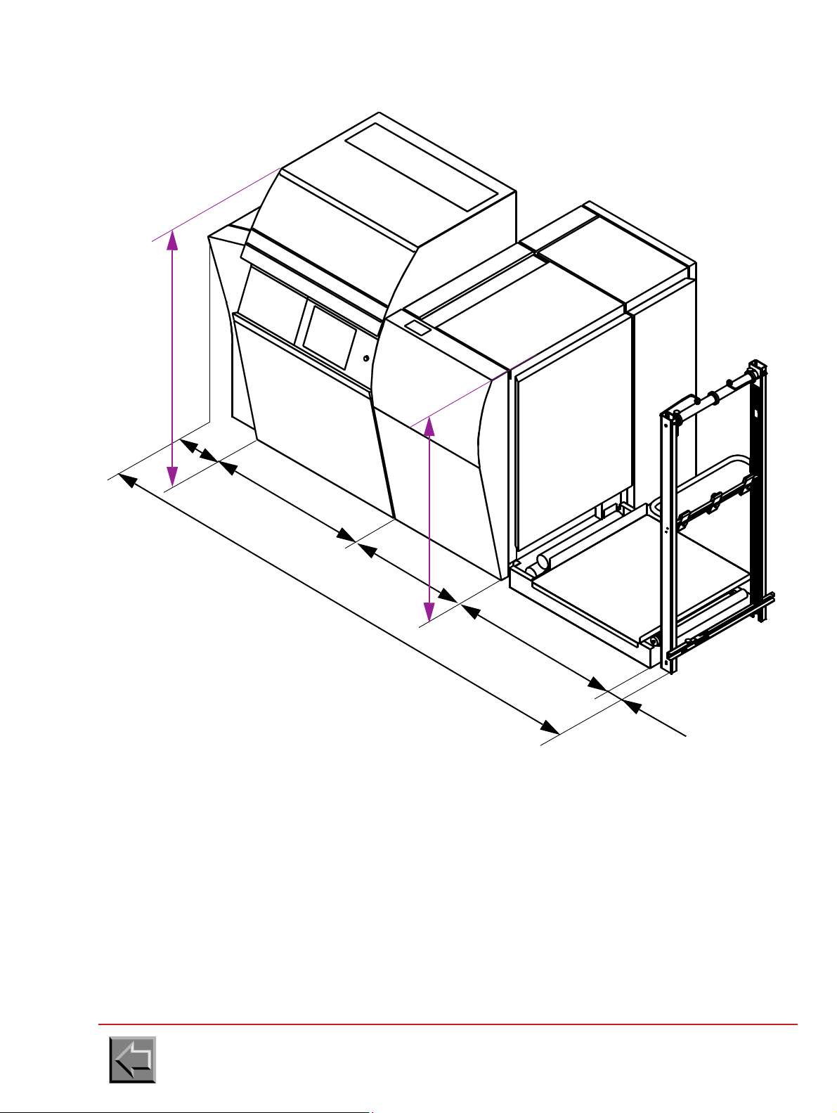
STANDARD PRINTER
Print
module
Fixing
module
Footbrige
1030
1000
790
410
3310
Unfolder
80
1720
1425
Site preparation manual
VARYPRESS 200
Go to "Table of contents"
2-2
Page 19

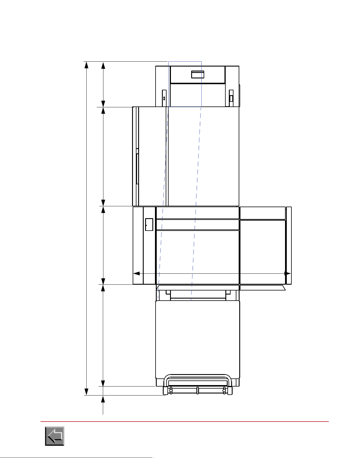
Site preparation manual
POST-PROCESSING
FLASH
FIXING
MODULE
PRINT
MODULE
FOOTBRIDGE / UNWINDER
1000790
2260
410
EXTRACTION
1600
1073
840
EXTRACTION
60
VARYPRESS 200
STANDARD PRINTER
Go to "Table of contents"
2-3
Page 20

S.E.D. PRINTER
1030
1000
790
500
3400
80
1720
1425
Print
module
Fixing
module
Footbrige
Unfolder
Site preparation manual
VARYPRESS 200
Go to "Table of contents"
2-4
Page 21
S.E.D. PRINTER
PRINTER
FOOTBRIDGE
103080
UNFOLDER
PAPER CHUTE
POST-PROCESSING
1000790
3400
500
1600
maxi.
PRE-PROCESSING
Site preparation manual
VARYPRESS 200
Go to "Table of contents"
2-5
Page 22
Site preparation manual
1000
510
8
0
0
Rear view
Overflow pipe
80 mm
VARYPRESS 200
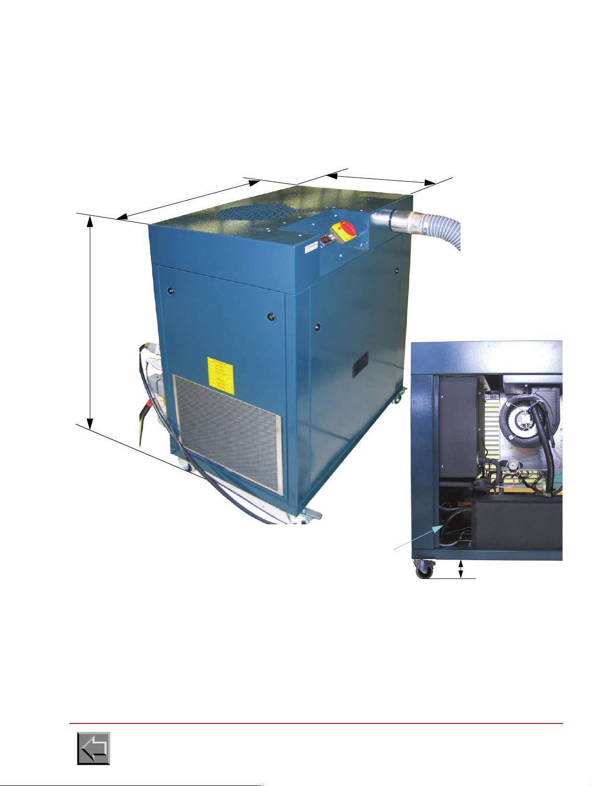
2.2.2 Air conditioning unit for write heads
Dimensions
Lenght: 800 mm
Width: 510 mm
Height: 1000 mm
Weight: 80 Kg
It is recommended to insert a water collecting pan under the air-conditioning unit because water can
flow by the overflow pipe when the air-conditioning unit has an incident (failure of the water level
sensor, the resistance or the thermostat).
When the buildings are wet, it is recommended to use the air-conditioning to drain the ambient air
(complementary information on operation is given in the air-conditioning unit manual).
To dehumidify the ambient air, it is necessary either to join this overflow pipe to the sewer, or to
collect water in a collecting pan under the air-conditioning unit.
Go to "Table of contents"
2-6
Page 23

Layout
FOOTBRIDGE
VARYPRESS 200
Air conditioning unit
OPERATOR
1000 maxi
Cable L=1.9m
Pipe L=1.7m
FOOTBRIDGE
VARYPRESS 200
OPERATOR
1400 maxi
300 maxi
Air conditioning unit
1500 maxi
The air-conditioning
unit must be
positioned in this
area
Site preparation manual
VARYPRESS 200
Go to "Table of contents"
2-7
Page 24
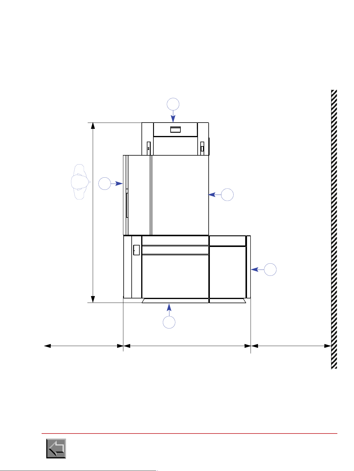
2.2.3 Floor space requirements
2260
1600 10001000
1
4
2
3
PRE-PROCESSING
4
PRINTER
POST-PROCESSING
The floor space requirements defined in this section are the minimum requirements. If the printer is
installed in too small an area, problems will occur when operating the printer.
Site preparation manual
VARYPRESS 200
1 Operator reference side.
2 Access for paper loading, paper splicing, toner refilling and write heads cleaning.
3 Access for paper unloading.
4 Access for field engineer.
Go to "Table of contents"
2-8
Page 25

Doors and covers opening
890
2315
500
Filter door
Toner bottle door
Side door
Front door
790
790
835
460
Site preparation manual
VARYPRESS 200
Go to "Table of contents"
2-9
Page 26

2.2.4 Raised floor cutouts
FIXING
MODULE
PRINT
MODULE
POST-PROCESSING
PLAN VIEW
PRE-PROCESSING
1
2260
1600
840
6
4
5
70x70
200
150
100
100
260
3
565
350
600
70x70
If the floor is a standard computer room raised floor, cut the floor tiles according to figure 1-4 for the
power and interface cables.
Site preparation manual
VARYPRESS 200
1 Operator reference side.
2 8 casters and 4 jacks enabling machine immobilization following installation
3 Raised floor cutout for interface cables.
4 Raised floor cutout for power cables
or
5 Framework chute passage for power cables (5).
6- Floor cutout for connecting the pre/post-processing interfaces.
Go to "Table of contents"
2-10
Page 27

Site preparation manual
Ø200
Ø315
2100 m3/h (optimum)
VARYPRESS 200
2.2.5 Installing a pumping system at the filtration unit outlet
2.2.5.1 Standard filtration
Characteristics at printer output
- Air temperature: 80ºC
- Air outlet dimensions: diameter 200 mm or diameter 315 mm
- Optimum air flow: 2100 m
3
/h at printer output
Recommendations
- Installation will be carried out in compliance with current building safety standards.
- Check that there is no back pressure at the air flow outlet outside the building.
Characteristics of NIPSON turbine (can be provided by the customer):
50 Hz
60 Hz
Air flow rate Voltage Maxi. current Power
3
2800 m
3360 m
/h
3
/h
380V - 420V tri 10.7 A 5.5 kW
380V - 420V tri 17 A 9.5 kW
Characteristics of hot air and smoke extraction with NIPSON turbine
- Pipe diameter: 200 mm
- maximum length: 20 m
-
maximum number of elbow joints
: 3 with 90º bend
or 2 with 90º bend + 2 with 45º bend
Go to "Table of contents"
2-11
Page 28

Simplex installation
The turbine can be delivered with the
provided by the customer
Delivered with the printer
printer or provided by the customer
Turbine installation,
interior or external
direct starter
auxiliary command cable
1,720 m
0,5 m
mains
input
ground
Flexible pipe
of 1 m
Site preparation manual
VARYPRESS 200
Go to "Table of contents"
2-12
Page 29

Site preparation manual
valve Ø 200
ground
Flexible pipe
of 1 m
The turbine can be delivered with the
provided by the customer
Delivered with the printer
printer or provided by the customer
Turbine installation
interior or external
1.720 m
0,5 m
hood
direct starters
auxiliary command cable
mains
input
VARYPRESS 200
Example of duplex installation
Go to "Table of contents"
2-13
Page 30

valve Ø 200
ground
Flexible pipe
of 1 m
Turbine installation
interior or external
1.720 m
0,5 m
hood
direct starters
auxiliary command cable
mains
input
The turbine can be delivered with the
provided by the customer
Delivered with the printer
printer or provided by the customer
Site preparation manual
VARYPRESS 200
Another example of duplex installation
Go to "Table of contents"
2-14
Page 31

Site preparation manual
Filtration option
included in the
printer
Smoke filters
2.2.5.2 Option with internal smoke filtration
This option is available for VaryPress 200-10 and VaryPress 200-20 printers but not for VaryPress
200-30 printers.
VARYPRESS 200
Go to "Table of contents"
2-15
Page 32
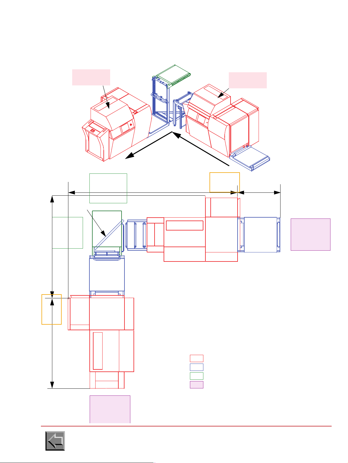
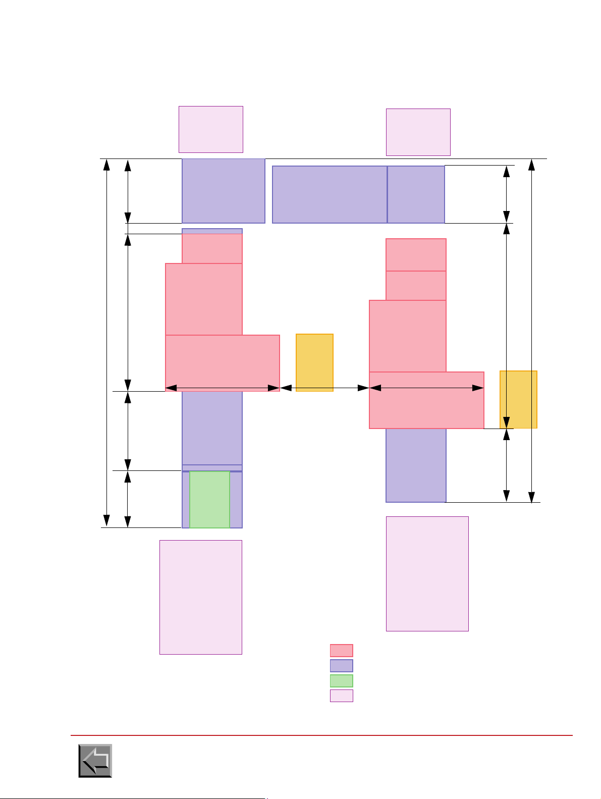
Site preparation manual
RECTO
PRINTER
input
output
paper
passage
RECTO
PRINTER
VERSO
PRINTER
INPUT
FOOTBRIDGE
POST-
PROCESSING
POST-
PROCESSING
PRE-
PROCESSING
LOOP
SHORT HOOD
TURNER
1 0304440
2550
2200
VERSO
PRINTER
NIPSON printer
Complement for L T.E.D. option
Complement for double simplex
Pre/post-processing
FOOTBRIDGE
T. E . D.
POST-
PROCESSING
AIR
CONDITIONING
UNIT
AIR
CONDITIONING
UNIT
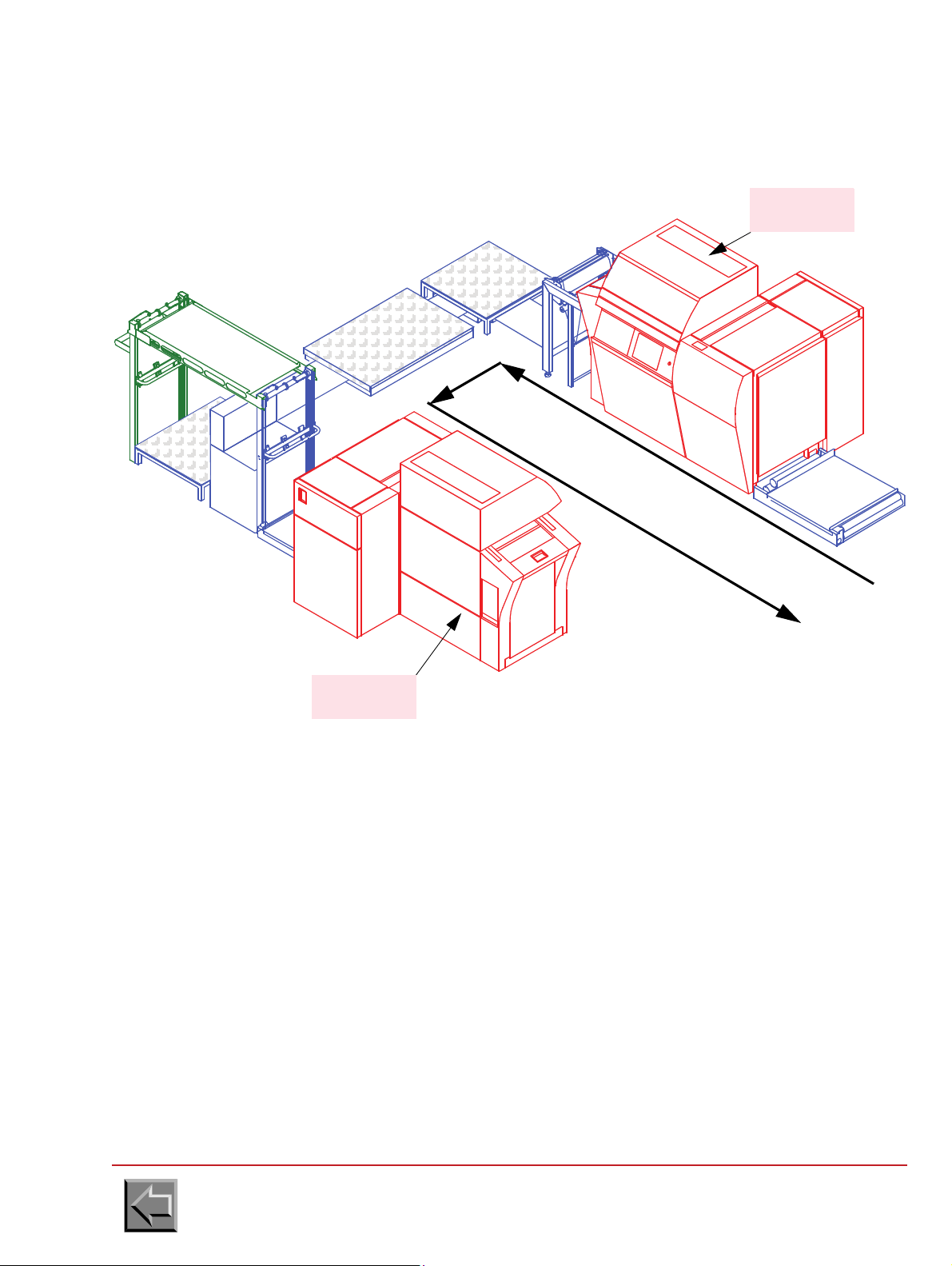
2.2.6 Location of the T.E.D. printer
2.2.6.1 L-shaped installation (standard)
VARYPRESS 200
Go to "Table of contents"
2-16
Page 33
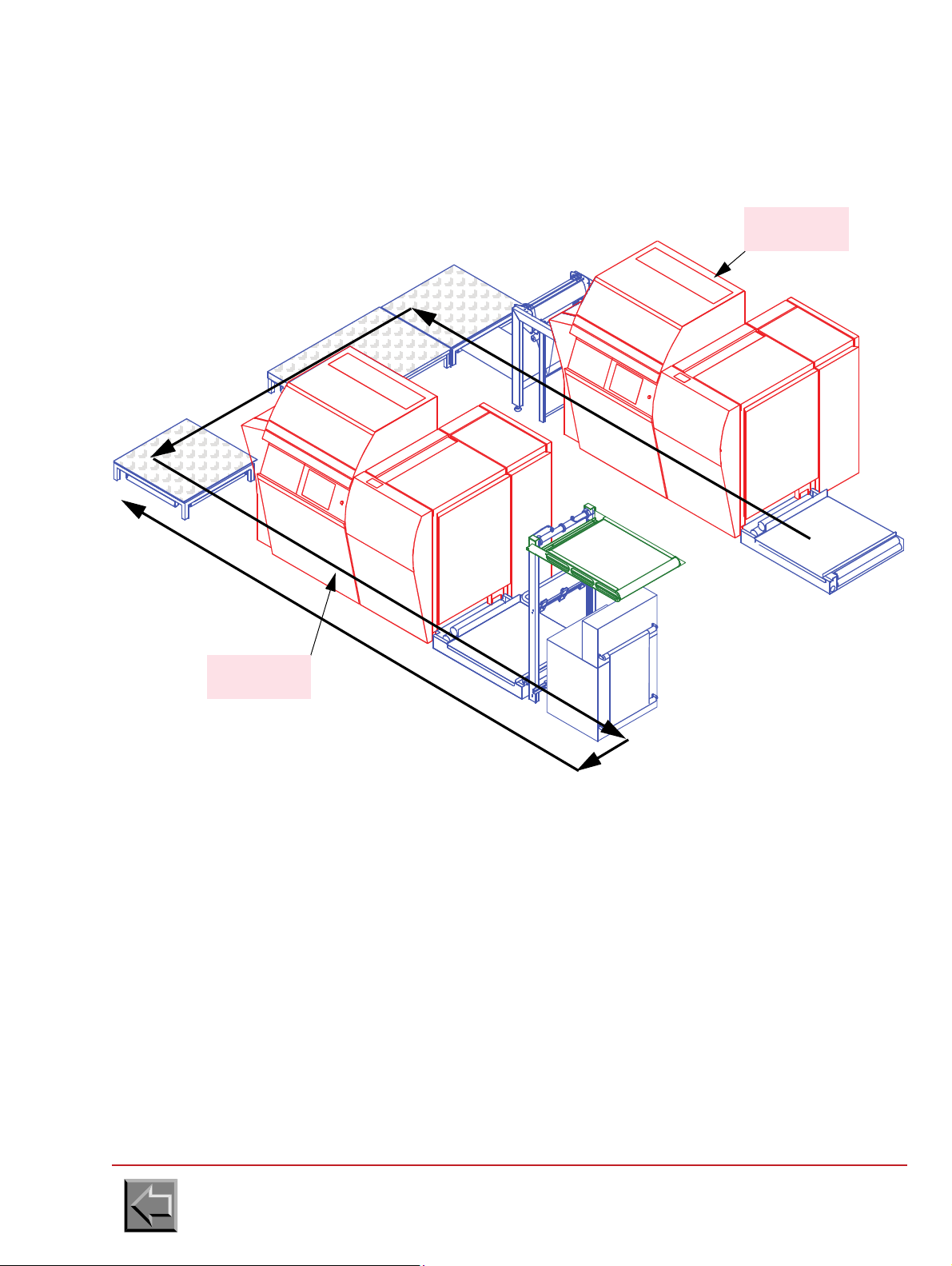
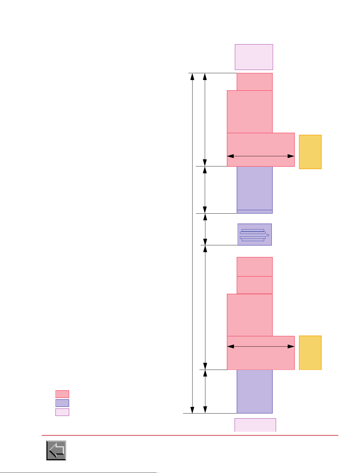
2.2.6.2 U-shaped installation
RECTO
PRINTER
VERSO
PRINTER
input
output
passage
paper
Site preparation manual
VARYPRESS 200
Go to "Table of contents"
2-17
Page 34
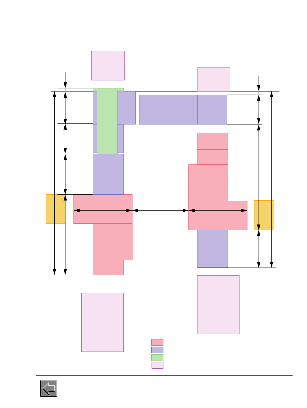
3040
1030
PRINTER
RECTO
INPUT
FOOTBRIDGE
LOOP
90011802200
5070
800
4970
T. E. D .
or PRE-
PAPER
PROCESSING
PROCESSING
PRINTER
INPUT
FOOTBRIDGE
UNFOLDER +
UNFOLDER
TURNER
TURNER
LOOP
LONG HOOD
or PRE-
PAPER
PROCESSING
POST
PROCESSING
POST
PLATFORM
VERSO
U-shaped installation
NIPSON printer
Complement for U T.E.D. option
Complement for double simplex
Pre/post-processing
80
1600 1600
100
1600 to 2300
790
AIR
CONDITIONING
UNIT
AIR
CONDITIONING
UNIT
Site preparation manual
VARYPRESS 200
Go to "Table of contents"
2-18
Page 35
2.2.6.3 S-shaped installation
input
output
paper
passage
VERSO
PRINTER
RECTO
PRINTER
Site preparation manual
VARYPRESS 200
Go to "Table of contents"
2-19
Page 36
Site preparation manual
3040
1030
RECTO
PRINTER
INPUT
FOOTBRIDGE
LOOP
9001180 2200
5220
800
4970
T. E. D .
PRE-
PROCESSING
PROCESSING
INPUT
FOOTBRIDGE
UNFOLDER +
TURNER
TURNER
LOOP
HOOD
POST
PROCESSING
POST
PLATFORM
S-shaped installation
NIPSON printer
Complement for S T.E.D. option
Complement for double simplex
Pre/post-processing
1600
790
PROCESSING
POST
VERSO
PRINTER
1600 1300 to 2000
150
AIR
CONDITIONING
UNIT
AIR
CONDITIONING
UNIT
VARYPRESS 200
Go to "Table of contents"
2-20
Page 37

2.2.6.4 Z-shaped installation
RECTO
PRINTER
input
output
paper
passage
VERSO
PRINTER
Site preparation manual
VARYPRESS 200
Go to "Table of contents"
2-21
Page 38

Z-shaped installation
900 1180 2200
5070
800
3040
1030
4070
PRE-
TRAITEMENT
1600
790
PROCESSING
POST
1600
1300 to 2000 1600
RECTO
PRINTER
INPUT
FOOTBRIDGE
LOOP
T.E.D.
INPUT
FOOTBRIDGE
UNFOLDER +
TURNER
TURNER
LOOP
SHORT HOOD
PLATFORM
VERSO
PRINTER
NIPSON printer
Complement for Z T.E.D. option
Complement for double simplex
Pre/post-processing
AIR
CONDITIONING
UNIT
AIR
CONDITIONING
UNIT
Site preparation manual
VARYPRESS 200
Go to "Table of contents"
2-22
Page 39

2.2.6.5 I-shaped installation (in line)
RECTO
PRINTER
input
output
paper
passage
VERSO
PRINTER
Site preparation manual
VARYPRESS 200
Go to "Table of contents"
2-23
Page 40
Site preparation manual
Pre/post-processing
RECTO
PRINTER
INPUT
FOOTBRIDGE
LOOP
900 1180 2200
8350
1030
T. E. D .
PRE-
PROCESSING
INPUT
FOOTBRIDGE
UNFOLDER +
TURNER
i-shaped installation
NIPSON printer
Complement for i T.E.D. option
1600
PROCESSING
POST
VERSO
PRINTER
1600
3040
AIR
CONDITIONING
UNIT
AIR
CONDITIONING
UNIT
VARYPRESS 200
Go to "Table of contents"
2-24
Page 41

Site preparation manual
VARYPRESS 200
2.3 ELECTRICAL REQUIREMENTS
2.3.1 Installation conditions
a. An insulated grounding connector that is identical in size, insulation material, and thickness to
the grounded and ungrounded branch-circuit supply connectors except that it is green with or
without one or more yellow stripes is to be installed as part of the branch circuit that supplies
the unit or system.
b. The grounding connector mentioned above is to be grounded to earth at the service equipment
or other acceptable building earth ground such as the building frame in the case of a high rise
steel frame structure.
c. The plug receptacles in the vicinity of the unit or system are all to be of a grounded type, and
the grounding connectors serving these receptacles are to be connected to earth ground at the
service equipment or other acceptable building earth ground, such as the building frame in the
case of a high rise steel frame structure.
d. The printer is compatible with the electric networks TT, TN (the neutral is connected to the
earth), and IT (the neutral is isolated from the earth).
2.3.2 Leakage current
Never operate the machine with grounding connector disconnected.
2.3.3 Mains power
Caution: Since the T.E.D. printer is composed of two printers, its power consumption is double that
of the standard machine.
The standard printer can operate with the following three phase mains power:
a. 400V - 50 Hz or 60 Hz
Voltage tolerance: +10 %, -10 %
Frequency tolerance: + 1 Hz
Four-wire power cable: 3 phases and ground.
b. Power consumption:
WARNING
The machine has a high leakage current. Grounding circuit
continuity is vital for safe operation of machine
Print speed
50 m/min 70 m/min 90 m/min
Power consumption during printing
with flash power value: 100%
Power consumption during printing
with flash power value: 80%
Power consumption on standby 1 kW 1 kW 1 kW
Current consumption 27 A 36 A 45 A
Go to "Table of contents"
19 kW 25 kW 33 kW
15 kW 20 kW 27 kW
2-25
Page 42

Site preparation manual
2
0
8
V
4
0
0
V
Transformer 40 kVA
for 1 printer
L1
L2
L3
L1
L2
L3
Ground
Ground
400 V
Printer
breaker
80 A
Customer
breaker
125 A
Curve D
Cable 25 mm
2
- AWG 4
Cable 16 mm
2
- AWG 6
2
0
8
V
4
0
0
V
Transformer 80 kVA
for 2 printers
L1
L2
L3
L1
L2
L3
Ground
Ground
400 V
Printer A
breaker
80 A
Customer
breaker
250 A
Curve D
L1
L2
L3
Ground
Printer B
breaker
80 A
Cable 50 mm
2
- AWG 1 Cable 16 mm2 - AWG 6
VARYPRESS 200
A transformer 208V/400V can be used to connect the printer(s)
Go to "Table of contents"
2-26
Page 43

2.3.4 Main circuit breaker
20 cm
Earth wire
Tags
D
internal
= 8 mm
NOTE: If the printer is directly connected to the mains, a "mushroom" emergency stop button
must be placed in the installation (responsibility of the customer). It must cut any source of
energy on the whole installation.
This emergency stop button must separate the contacts with a distance of at least 3 mm.
50 Hz:
- The gauge of the printer circuit breaker is 80A.
The circuit breaker of the printer is a protection member.
- The capacity of the customer emergency stop button circuit must be 80 A (curve D), and if
there is a differential breaker, its capacity must be 300 mA (because of the high leakage
current).
60 Hz:
- The gauge of the printer circuit breaker is 80A.
The circuit breaker of the printer is a protection member.
Site preparation manual
VARYPRESS 200
- The capacity of the customer emergency stop button circuit must be 80 A / 400 V (curve D) (or
125A in 208V, see figure on previous page), and if there is a differential breaker, its capacity
must be 300 mA (because of the high leakage current).
2.3.5 Printer main cable
50 Hz printers are supplied with cable.
Since the 60 Hz printers are supplied without cable, the installer must check that the main cable
complies with local standards:
- The 60 Hz cable must have 4 conductors AWG 6 minimum (16 mm
- The color of the wires must comply with local standards.
- On the printer end, the conductors must be fitted with closed D8 type terminal tags.
- On the mains power supply box end, the conductors must be fitted with tags compatible with
the type of box.
2
).
There are 2 ways of feeding the main cable under the machine, see paragraph 2.2.4.
Go to "Table of contents"
2-27
Page 44

Site preparation manual
VARYPRESS 200
2.3.6 Pre and post processing ground wire
The pre and post processing ground wires must be fitted, on the printer end, with closed D5 type
terminal tags.
2.3.7 Air conditioning unit for write heads
Mains power :
- 230V 50Hz or 60Hz
- Power consumption: 2 kW
Connect the air conditioning unit to a circuit breaker, 15A, 2 poles (Curve D).
The air conditioning unit is supplied with one connector (to plug on the air conditioning unit) but
without the main cable, the installer must install a cable which complies with the local standards:
- Three-wire power cable, hard use type (SJT or equivalent): Single-phase and ground.
-
The plug must complies with the local standards (e.g. for USA & Canada: 250V 15 A, ref 6-15R)
2.3.8 Electrical connection of web cleaner option
Mains voltage 400 V - 3 phases 208 V - 3 phases
Frequency 50 Hz 60 Hz
Motor output 1.1 kW 1.3 kW
Motor voltage 230/400 V 120/208 V
Air displacement
Connect the web cleaner to a circuit breaker, 3A, 3 poles (Curve C).
Go to "Table of contents"
135 m
3
/h 135 m3/h
2-28
Page 45

Site preparation manual
Mains power :
- 230V 50Hz or 60Hz
- 1 phase + Neutral
- Power consumption: 1 kW
Connect the motorised loop to a
circuit breaker, 15A (Curve D).
VARYPRESS 200
2.3.9 T.E.D. motorised loop (U-shaped or S or Z)
Go to "Table of contents"
2-29
Page 46

2.3.10 U.P.S.
3
4
5
6
7
TB2
Ph
N
G
Ph
N
G
P90
on ALFIX board
47292035-407 min.
U.P.S.
U.P.S.
supply
output
Main
supply
Jumpers to remove
TB2
U.P.S.
P90-2
P90-3
before connecting
the U.P.S.
P90-1
Source
Dry
contacts
input
To ensure the P. C . safety, a U.P.S. can be added with the following characteristics:
- U.P.S. 1000 VA
- need of a dry contact board.
The U.P.S. and the dry contact board are not supplied by NIPSON but the following
equipments are recommended because they were tested with the printer:
Manufacturer U.P.S. Board, dry contacts
Site preparation manual
VARYPRESS 200
LIEBERT GXT2-1000 2UAPC
Smart UPS 1000VA
RELAYCARD-INT board,
dry contacts / AS400
Connection to the printer:
- Remove the jumpers across terminals TB2 3-4 and TB2 5-6 and plug the U.P.S.
- Unplug the P90 connector of ALFIX and plug the output of the dry contacts on ALFIX board
using one female Micro connector, 1x3 (pitch: 2,5).
Go to "Table of contents"
2-30
Page 47

2.4 REMOTE MAINTENANCE
The remote maintenance system must be installed to enable the field technicians and engineers
to remotely access the printer requiring a diagnostic or an intervention (software update ...).
Required Equipment
1. An analogical telephone line reserved for connection of the modem, providing direct-number
access (direct line or possibility of line selection when connecting to the telephone
switchboard).
2. A telephone line making it possible to converse and give instructions during the remote
maintenance session.
3. An electrical socket close to the printer in order to plug in the modem.
4. A modem: USRobotics Sportster 33600 fully equipped (to find out about the modem
characteristics required, contact International Technical Support tel.: +33 (0)3-84-54-59-59 or
fax +33 (0)3-84-54-52-55).
5. A cable to connect the modem to the PC (9-pin female connector EIA232 for P.C.).
Site preparation manual
VARYPRESS 200
6. A cable to connect the OpenDrive PC to the connectors panel.
7. A PPU3 connection cable.
8. A piece of Velcro tape (to fix the modem).
NOTE: Parts 1. to 3. are provided by the customer.
Parts 4. and 5. are provided by the local maintenance.
Parts 6. to 8. are delivered with the printer.
Go to "Table of contents"
2-31
Page 48
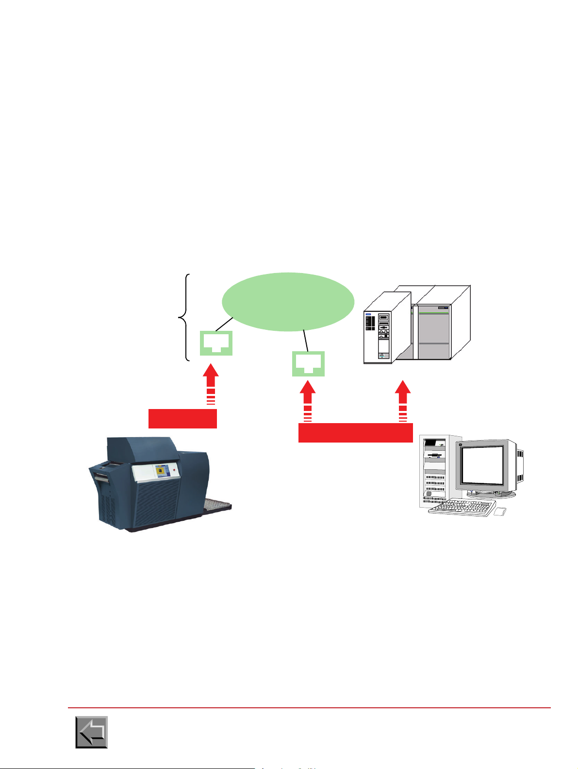
Site preparation manual
Gateways
Bull, IBM, DEC, Unix...
2 Ethernet cables
Ethernet cable
10/100/1000 BaseT 20 m
10/100/1000 BaseT
PRINTER
Print Server Platform
Sockets
RJ45
Check
the presence
Ethernet LAN
(Factory)
10 m
2.5 INTERFACE CONNECTION
PELV (Protected Extra-Low Voltage) safety notice
To ensure the extra-low voltage integrity of the equipment, connect only equipment with mainsprotected electrically-compatible circuits to the internal ports.
CAUTION: Your printer will be connected to a host system. If Nipson does not deliver this system,
to avoid very nasty surprise with the installation, please check the compatibility of this system and
the version recommended by Nipson.
web site http://bbs.nipson.com ; Call center tel.: +33 (0)3 84 54 59 59.
2.5.1 Printer with LAN
2.5.1.1 Connection to the factory network
VARYPRESS 200
Go to "Table of contents"
2-32
Page 49
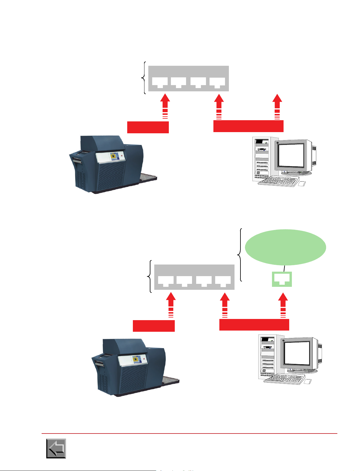
Site preparation manual
2 Ethernet cables
10/100/1000 BaseT
Print Server Platform
Ethernet cable
10/100/1000 BaseT 20 m
PRINTER
supplies
to provide
Switch or HUB 10/100/1000 BASE-T
10 m
Check the
presence
Ethernet LAN
(Factory)
2 Ethernet cables
10/100/1000 BaseT
Print Server Platform
RJ45
Ethernet cable
10/100/1000 BaseT 20 m
PRINTER
supplies
to provide
Switch or HUB 10/100/1000 BASE-T
Note: The platform acts as bridge
separating two fields from network LAN.
10 m
2.5.1.2 Connection to the adapted network
VARYPRESS 200
2.5.1.3 Connection to the isolated network
Go to "Table of contents"
2-33
Page 50

Site preparation manual
VARYPRESS 200
2.5.2 Connection of the printer to the network
The customer is responsible for preparing the printer connection to the Ethernet network of the firm
before the printer is supplied.
Configure the printer network address as described in paragraph 3.2.5.16 of the Product Manual (in
Configuration -> Change network configuration).
WARNING: expression "Broadcast Address of Printer" doesn't mean a gateway address. For
gateway address configuration , please contact Nipson International Support.
2.5.2.1 VPServer connection
The Ethernet cable is provided with the printer, and needs to be connected to the Ethernet network
of the company.
2.5.2.2 U_NetPSF connection
The Ethernet cable is provided with the printer, and needs to be connected to the Ethernet network
of the company.
The IPDS licence for the U_NetPSF connection has to be ordered to NIPSON during the installation
of the printer.
2.5.2.3 E_NetPSF connection
The Ethernet cable is provided with the printer, and needs to be connected to the Ethernet network
of the company.
The IPDS licence for the E_NetPSF connection has to be ordered to NIPSON during the installation
of the printer.
This licence has a lifetime of 1 year and has to be extended every year.
2.5.2.4 OpenPage connection
The Ethernet cable is provided with the printer, and needs only to be connected to the Ethernet
network of the company.
Go to "Table of contents"
2-34
Page 51

Site preparation manual
VARYPRESS 200
2.5.3 Connection to the host system
2.5.3.1 VPServer connection
Refer to the VaryPress PrintServer user guide.
2.5.3.2 Connection to PRESS V4
PRES software from PrintSoft is configured by the registry of Windows.
Launch regedit and select directory:
HKEY_LOCAL_MACHINE\SOFTWARE\PrintSoft\PReS\IPDS\prn1
- The main parameters to be configured are:
DeviceName=TCPIP,192.90.225.108,5001
DeviceSpeed=HIGH
DEV_UNITS=1
PageBuff=2
PRSTRACE=0
QUESIZE=125
ACK_PAGES=100
TCPMaxWrite=8192
TCPMaxTimeout=180
SRA=0
IOCAType=1
Rel_Metrics=0
PrintDebug=Off
"QUESIZE" parameter should indicate the number of lead pages of the printer. The value of 127
suits simplex printer. For duplex printer, use the value of 250 to ensure that the printer operates
correctly, especially during restarts. "Device Name" parameter must be updated with printer TCP
address and port value given by the customer.
Go to "Table of contents"
2-35
Page 52

Site preparation manual
VARYPRESS 200
2.5.3.3 Connection to PRINTNET V3 from GMC
PrintNet configuration
PRINTNET software from GMC is associated with a configuration file named printnet.ini.
This file contains a group called [Machines]" which should contain the logic name associated with
the printer, for example IPDS600 for a 600DPI printer.
Printnet.ini must also contain a group defining the characteristics of the printer. The logic name of
the printer in the [Machines]" group is the name of this group (for example "[IPDS 600]"). The
important parameters are the height and the width of printing in dots. The "FontCaps" parameter
must be equal to 2. The PrintCaps" parameter must be equal to 0 for a standard machine and to 64
for a SpotColor equipped machine.
Machine parameters for NIPSON's printers, IPDS 600 and IPDS 300 groups:
- [IPDS 600]
MachineType=131
MaxWidth=11070
MaxLength=21600 with a VP200, 21450 with a VP400
nonprintablemargin=0
Resolution_x=600
Resolution_y=600
FontCaps=2
Charset=ANSI
PrintCaps=0
Negative=1
BitmapFormats=255
;SpotColors=
Lde=C:\GMC\PMANAGER\ipds600\pmlouts
Overlay=C:\GMC\PMANAGER\ipds600\pmovls
Font=C:\GMC\PMANAGER\ipds600\pmfonts
Prt=C:\GMC\PMANAGER\ipds600\pmprt
Charset=ANSI
- [IPDS 300]
MachineType=132
MaxWidth=5535
MaxLength=10800 with a VP200, 10725 with a VP400
nonprintablemargin=0
Resolution_x=300
Resolution_y=300
FontCaps=2
Charset=ANSI
PrintCaps=0
Negative=1
BitmapFormats=255
;SpotColors=
Lde=C:\GMC\PMANAGER\ipds300\pmlouts
Overlay=C:\GMC\PMANAGER\ipds300\pmovls
Font=C:\GMC\PMANAGER\ipds300\pmfonts
Prt=C:\GMC\PMANAGER\ipds300\pmprt
Charset=ANSI
Go to "Table of contents"
2-36
Page 53

Site preparation manual
VARYPRESS 200
PRINTMANAGER connection
The PRINTMANAGER software is associated with a configuration file named pm_ipds.ini.
This file contains a group called "[PrintManager]" which should contain the logic name associated
with the printer, for example IPDS600 for 600 DPI printer (parameter "DefLoginName").
It must contain an "[IPDS]" group which contains the controller type ("ControllerType" parameter)
equal to NIPSON, the emulated printer ("KompatibleType" parameter) equal to 3900 and the buffer
size (" PageBuffer" parameter) equal to 127 for a STANDARD machine and (" PageBuffer_Duplex "
parameter) equal to 250 for a T.E.D. machine.
The value of Max_Transfer_Length parameter must be in accordance with printer configuration,
parameter "IPDS data buffer size".
On the other hand, in using IBM channel connection the group " [PrintManager] " must contain the
printer address on IBM channel ("Channel" parameter), the mode ("Channel_Mode" parameter) set
to 0 and the type of interface board ("Card_Type" parameter equal to PCI or an other value in
accordance with GMC engineer).
NipsonSplitOverlays must be equal to:
- 0 for VARYPRESS 200, VARYPRESS 400 and NIPSON7000
- 1 for N8000
- 2 for VaryPress Txxx.
In using TCP/IP connection the group " [PrintManager] " must contain the type of interface board
("Card_Type" parameter equal to TCP). Moreover, for this connection, in the file pm_ipds.ini, a
special group named "[TCP_IP]" which contains printer address ("TCP_Address" parameter ) and
IP port ("IP_Port" parameter ) must be added.
Don't cancel unused parameters, insert a " ; " character at the beginning of the line for disabled it.
- Example of pm_ipds.ini:
[PrintManager]
Language=English
ErrorLevel=30
JobErrorLogFile=No
DailyErrorLogFile=No
LogFileToView=Machine
JobReport=1
DefLoginName=IPDS480
LoginState=0
EndofJobPart=0
JDE_Filter=type
IndexFile=1
DataScanDestination=NONE
- [IPDS]
Channel=8
Channel_Mode=0
Card_Type=TCP
ControllerType=NIPSON
KompatibleType=3900
PageBuffer=125
PageBufferDuplex=250
StackReceivedPage=0
Go to "Table of contents"
2-37
Page 54

Site preparation manual
VARYPRESS 200
WaitResetTime=10
Max_Transfer_Length=16
AutoRestartAfterPaperEnd=Yes
DefaultFontMetrics=FIXED
ResponseTimeout=120
Exception_UndefinedCharacter=0
Exception_PrintOutsidePage=0
Exception_AllOther=0
PrintExceptionNumber=0
UseNewLoadImageCommand=1
PictureCompression=2
OverlayCompression=2
PagesPerAcknowledge=1
AutoRestartAfterException=Yes
CleanPageBufferAfterException=Yes
IgnoreEmptyDoubleByteSections=Yes
LCA_Programm=C:\GMC\PM_IPDS\BOOT\LCA.BIN
CCA_Programm=C:\GMC\PM_IPDS\BOOT\PCI_dwn.BIN
JPEGQuality=70
EPSResolution=machine
EPSBitsPerPixel=1
UsePageSegments=1
NumberOfPagesegments=127
IntercomTraceLevel=0
SpotColor1=BLUE
SpotColor2=RED
SpotColor3=MAGENTA
SpotColor4=GREEN
SpotColor5=CYAN
SpotColor6=YELLOW
SpotColor7=BROWN
IncrementalRestartPage=0
InterkomPCIDelay=50
NipsonSplitOverlays=0
- [TCP_IP]
IP_Port=5001
TCP_Address=172.25.16.32
BufferSize=1452
WARNING: Many customers use several release of PrintManager. Check in WIN.INI file the
content of group [PrintNet]. The PM_IPDS.INI " parameter must be equal to the
directory of used pmanager.exe file.
Go to "Table of contents"
2-38
Page 55
Site preparation manual
VARYPRESS 200
2.5.3.4 Connection to PRINTNET T from GMC
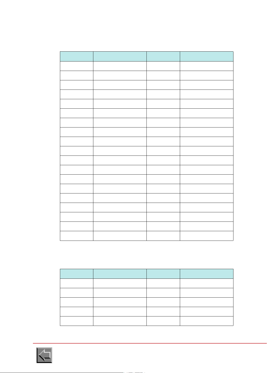
The printing characteristics must be as follows:
Go to "Table of contents"
2-39
Page 56

Site preparation manual
VARYPRESS 200
The connection configuration must be as follows, with the Page Buffer parameter set to 128 in case
of a simplex printer and 256 for a duplex printer.
Go to "Table of contents"
2-40
Page 57

Site preparation manual
VARYPRESS 200
2.5.3.5 Connection to OS390 + MVS from IBM
The site system engineer must register the printer on the IBM system and check that the PSF
software is installed.
If the printer replaces another printer already connected to the host system, the registration exists.
The system engineer has therefore nothing to modify.
The IBM system must be linked to the Ethernet network, once the TCP/IP software has been
installed and actuated.
For example, to add a printer with OS/390 or MVS, follow these steps:
1. Printer registration in the JES2.
(see IBM documentation: JES2 Initialization and Tuning Reference)
It is a printer in page mode, commanded by an FSS (Functional SubSystem). The printer has
no physical address (unit), there is therefore no need to register it in the hardware
configuration.
Example of registration in the JES2PARM member:
FSSDEF(FSS7000) PROC=APSW7000
PRT20 FSS=FSS7000,MODE=FSS,PRMODE=(PAGE,LINE),CLASS=I,
TRKCELL=YES,UCS=0,NPRO=0,START=NO
There are three ways to activate printer parameters:
- system re-initializing; this way is never used because the high using rate of the system
- enabling dynamically printer parameters by using JES2 command "ADD". Example:
ADD FFSDEF(FSS7000) PROC=APSW7000
ADD FSS=FSS7000,MODE=FSS,PRTMODE=(PAGE,LINE),CLASS=I,
TRKCELL=YES,UCS=0,NPRO=0,START=NO
- enabling dynamically printer parameters by using InfoPrint Server capability (only with version
of OS/390 greater or equal to 3.8). In this case, the first and only parameter of the command is
"INV". See PSF documentation, about InfoPrint Server and Printer Inventory references.
Example:
ADD FSS=FSS7000,INV=toto
Where "toto" is the name of the database file containing printer parameters
2. Creation of the PSF procedure associated with the preceding registration:
(see IBM documentation: PSF/MVS System Programming Guide)
//APSW7000 PROC
//*
//**************************************** THE PSF WRITER PROCEDURE ************************************
//* IN PROCLIB LIBRARY
//*
//STEP01 EXEC PGM=APSPPIEP,REGION=4096K
//JOBHDR OUTPUT PAGEDEF=A08584, /* JOB SEPARATOR PAGEDEF */
// FORMDEF=0101LA,CHARS=GT5F /* JOB SEPARATOR FORMDEF */
//MSGDS OUTPUT PAGEDEF=L08080, /* MESSAGE DATASET PAGEDEF */
// FORMDEF=0101LA /* MESSAGE DATASET FORMDEF */
//FONT01 DD DSN=SYS1.FONTLIBB,DISP=SHR /* SYSTEM FONTS */
// DD DSN=SYS7.FONTLIB,DISP=SHR /* */
//PSEG01 DD DSN=SYS1.PSEGLIB,DISP=SHR /* SYSTEM PAGE SEGMENTS */
// DD DSN=SYS7.COMMON.AFPLIB,DISP=SHR /* */
Go to "Table of contents"
2-41
Page 58

Site preparation manual
VARYPRESS 200
//OLAY01 DD DSN=SYS1.OVERLIB,DISP=SHR /* SYSTEM OVERLAYS */
// DD DSN=SYS7.COMMON.AFPLIB,DISP=SHR /* */
//PDEF01 DD DSN=SYS1.PDEFLIB,DISP=SHR /* SYSTEM PAGEDEFS */
// DD DSN=SYS7.COMMON.AFPLIB,DISP=SHR /* */
//FDEF01 DD DSN=SYS1.FDEFLIB,DISP=SHR /* SYSTEM FORMDEFS */
// DD DSN=SYS7.COMMON.AFPLIB,DISP=SHR /* */
//* */
//PRT20 CNTL
//PRT20 PRINTDEV FONTDD=*.FONT01, /* FONT LIBRARY DD */
// OVLYDD=*.OLAY01, /* OVERLAY LIBRARY DD */
// PSEGDD=*.PSEG01, /* SEGMENT LIBRARY DD */
// PDEFDD=*.PDEF01, /* PAGEDEF LIBRARY DD */
// FDEFDD=*.FDEF01, /* FORMDEF LIBRARY DD */
// JOBHDR=*.JOBHDR, /* JOB HEADER SEPARATOR OUTPUT */
// JOBTRLR=*.JOBHDR, /* JOB TRAILER SEPARATOR OUTPUT */
// DSHDR=*.JOBHDR, /* DATA SET HEADER SEPARATOR */
// MESSAGE=*.MSGDS, /* MESSAGE DATA SET OUTPUT */
// BUFNO=30, /* NUMBER OF WRITE DATA BUFFERS */
// PAGEDEF=L08080, /* DEVICE PAGEDEF DEFAULT */
// FORMDEF=0101LA, /* DEVICE FORMDEF DEFAULT */
// CHARS=GT5F, /* DEVICE DEFAULT FONT SET */
// TRACE=NO /* BUILD INTERNAL TRACE */
// FAILURE=WCONNECT, /* ATTEMPT RECONNECT */
// DISCINTV=0, /* NO TIME OUT */
// MGMTMODE=IMMED, /* MAINTAIN SESSION */
// IPADDR=`192.44.50.150', /* IP ADDRESS OF NIPSON PRINTER */
//PRT20 ENDCNTL
//* */
Go to "Table of contents"
2-42
Page 59
Site preparation manual
VARYPRESS 200
2.5.3.6 Connection to InfoPrintManager from IBM
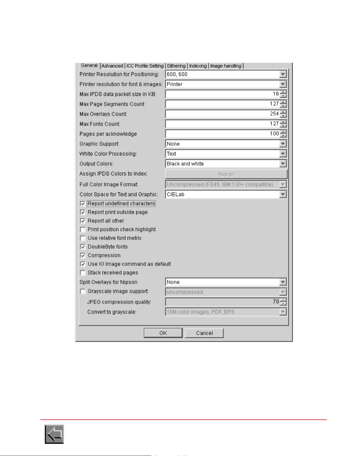
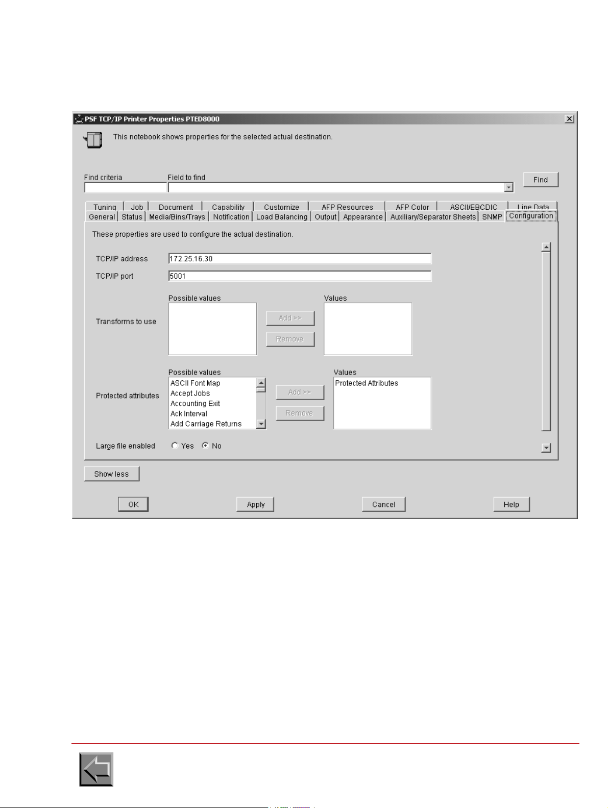
In the printer properties, configure the Configuration tab and Adjustments tab as follows:
Go to "Table of contents"
2-43
Page 60

Site preparation manual
VARYPRESS 200
2.5.3.7 SDP Protocol Network Interface (OpenPage)
- Internet @: supply the printer @
- Port number: 1090 (data)
NOTE 1: In the case of an OpenPage connection of type XTI, put 1050 for the port number.
NOTE 2: The port numbers and the type of acquisition (XTI or TCP) can be modified by the
administration menus of the printer.
Go to "Table of contents"
2-44
1091 (commands)
Page 61

Site preparation manual
VARYPRESS 200
2.6 UNPACKING AND INSTALLATION PREPARATION
So that the printer is unpacked and installed in the best possible conditions, the following points
must be considered when preparing the site.
2.6.1 Unloading the lorry
- Easy access for the lorry.
- Unloading bay required.
- Trolley required.
2.6.2 Unpacking the modules
- Outside: prepare a waterproof cover in case of rain.
- Inside: trolley required.
2.6.3 Moving the printer to the customer's computer room
- Trolley required, apart from the transporter's.
- If there are access ramps, a winch may be needed, depending on the slope.
- If there are stairs, a suitable trolley is required.
- Width of corridors: preferably greater than 1.20 m.
- In case of soft" floors (carpet, ...), prepare boards or a pallet truck.
- If there are lifts, check that the dimensions are compatible, and prepare a steel sheet to
facilitate movement into the lift.
ATTENTION
If there is a great difference of temperature or relative humidity
between the installation room (see § 1.3) and the packed machine, it
is necessary to keep the printer in its packing during a few hours
The fact of not respecting this instruction can involve risks of
before proceeding to the installation.
deterioration of the material.
Go to "Table of contents"
2-45
Page 62

Site preparation manual
VARYPRESS 200
Go to "Table of contents"
2-46
Page 63

Site preparation manual
VARYPRESS 200
3. Pre / post processor devices
3.1 IDENTIFICATION
The specification defines a protocol for exchange of data and hardware interface between the
printer and two pre and post processing and a camera system.
3.2 INTERFACE CONNECTOR DEFINITION
1. Pre post-processing device 1 connector (on printer interface side)
D-SUB 37 pins , Female
Nº PIN SIGNAL Nº PIN SIGNAL
1 TXD1_H 20 TXD1_L
2 RXD1_H 21 RXD1_L
3 VITRD1+ 22 0V (VITRD1-)
4 PP1PRT+ 23 0V (PP1PRT-)
5 +12V (NTPI1+) 24 NTPI1-
6SDP1+25SDP1-
7NC26NC
8NC27NC
9 PP1CNT+ 28 0V (PP1CNT-)
10 PP1MA+ 29 0V (PP1MA-)
11 M VP1+ 3 0 MVP1-
12 MVPSEC1+ 31 MVPSEC1-
13 SDPSEC1+ 32 SDPSEC1-
14 PP1DMAR+ 33 0V (PP1DMAR-)
15 PP1DARR+ 34 0V (PP1DARR-)
16 PLIPTC1+ 35 PLIPTC1-
17 IMPRESS1+ 36 IMPRESS1-
18 NC 37 NC
19 NC
Go to "Table of contents"
3-1
Page 64
Site preparation manual
VARYPRESS 200
2. Pre post-processing device 2 connector (on printer interface side)
D-SUB 37 pins , Female
Nº PIN SIGNAL Nº PIN SIGNAL
1 TXD2_H 20 TXD2_L
2 RXD2_H 21 RXD2_L
3 VITRD2+ 22 0V (VITRD2-)
4 PP2PRT+ 23 0V (PP2PRT-)
5 +12V (NTPI2+) 24 NTPI2-
6SDP2+25SDP2-
7NC26NC
8NC27NC
9 PP2CNT+ 28 0V (PP2CNT-)
10 PP2MA+ 29 0V (PP2MA-)
11 MVP2+ 30 MVP2-
12 MVPSEC2+ 31 MVPSEC2-
13 SDPSEC2+ 32 SDPSEC2-
14 PP2DMAR+ 33 0V (PP2DMAR-)
15 PP2DARR+ 34 0V (PP2DARR-)
16 PLIPTC2+ 35 PLIPTC2-
17 IMPRESS2+ 36 IMPRESS2-
18 NC 37 NC
19 NC
3. Camera system connector (on printer interface side)
D-SUB 9 pins , Female
Nº PIN SIGNAL Nº PIN SIGNAL
1PLIPTC+6 NTPI3-
2PLIPTC-7 0 V
3 CAMCNT+ 8 0 V (CAMCNT-)
4+12V (NTPI3+)90 V (INCCAM-)
5 INCCAM+
Go to "Table of contents"
3-2
Page 65

Site preparation manual
1/6"
VARYPRESS 200
3.3 INPUT/OUTPUT SIGNALS
3.3.1 Signals from printer to pre-post processing device
1. 1/6 of an inch displacement signal 1 (NTPI1) and (NTPI2)
The printer generates a positive pulse for each 1/6 inch paper movement. This signal is
designed to synchronize the Pre-Post-Processing device with the printer.
The ratio between low and high signals is one.
2. Paper movement direction (SDP1) and (SDP2)
This signal indicates the paper movement direction to the Pre-Post Processing device.
"0": Forward paper movement
"1": Backward paper movement
3. Paper movement direction switch contact (SDPSEC1) and (SDPSEC2)
This signal indicates the paper movement direction to the Pre-Post Processing device.
"0": Forward paper movement
"1": Backward paper movement
NOTE: This signal is the same as SDP1/2 with the difference that it is activated by a contact
switch only.
4. Paper movement (MVP1) and (MVP2)
The signal indicates to the Pre-Post Processing device that the paper is going to move. This
signal is activated at least 2 seconds before the printer starts.
NOTA: The two seconds anticipation time does not occur when a paper feed is activated.
This signal can be used by the post-processing device to start or stop the elements which
would otherwise always run..
"0": paper movement
"1": no paper movement
5. Paper movement switch contact (MVPSEC1) and (MVPSEC2)
Definition : See paper movement.
NOTA: This signal is the same as MVP1/2 with the difference that it is activated by a contact
switch only.
Go to "Table of contents"
3-3
Page 66
Site preparation manual
1L
0L
22ms < T < 25ms
VARYPRESS 200
6. Serial connection (RXD1_H, RXD1_L) and (RXD2_H, RXD2_L)
The printer transmits information to the Pre-Post Processing device through a serial
connection in differential mode ( RS422).
7. Sheet detection (PLIPTC1) and (PLIPTC2)
The printer generates a pulse every sheet of paper feed.
8. Printing state (IMPRESS1) and (IMPRESS2)
This signal indicates to the Pre-Post Processing device that the printer is in the printing state.
"0": printer in printing state
"1": printer is not in printing state
Go to "Table of contents"
3-4
Page 67

Site preparation manual
1L
0L
500ms < T < 1s
T
VARYPRESS 200
3.3.2 SIGNALS FROM PRE-POST PROCESSING DEVICE TO PRINTER
1. Pre-post processing device connected (PP1CNT) and (PP2CNT)
This signal indicates to the printer that a Pre-Post Processing Device is connected (but not
necessarily ready).
If the Pre-Post Processing Device is present, the printer can disable its internal stacker.
"0": connected
"1": not connected
2. Pre-post processing device ready (PP1PRT) and (PP2PRT)
Indicates to the printer that the Pre-Post Processing Device is ready for operation. This signal
is also used for an emergency stop (Hard stop).
"0": ready
"1": not ready
3. Speed reduce (VITRD1) and (VITRD2)
Request a speed reduction from the printer.
"0": speed reduction
"1": no speed reduction
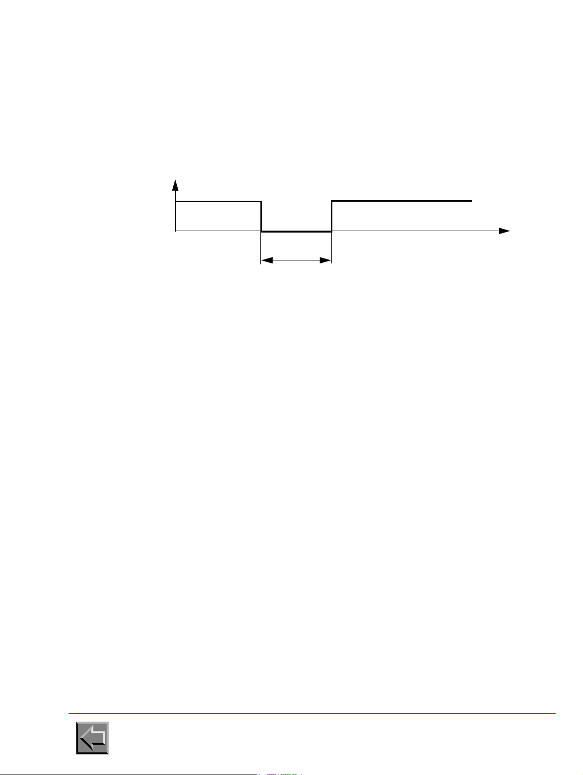
4. Printer start/stop by pre-post processing device (PP1MA) and (PP2MA)
The Pre-Post Processing Device number 1 transmits this signal to start or stop the printer (Soft
stop).
NOTA: This signal only used when PP1/2DMAR and PP1/2DARR are not used.
"0": stop
"1": start
5. Start request by pre-post processing device (PP1DMAR) and (PP2DMAR)
This signal indicates to the printer that it start.
NOTA: This signal is used with PP1/2DARR when PP1/2MA is not used.
"0": start command
"1": no start command
Go to "Table of contents"
3-5
Page 68

Site preparation manual
1L
0L
500ms < T < 1s
T
VARYPRESS 200
6. Stop request by pre-post processing device (PP1DARR) and (PP2DARR)
This signal indicates to the printer that it stop.
NOTE: This signal is used with PP1DMAR when PP1MA is not used.
"0": stop command
"1": no stop command
7. Serial connection (TXD1_H , TXD1_L) and (TXD2_H , TXD2_L)
The post-processing device number 1 transmits the information to the printer through a serial
connection in differential mode (RS422).
3.3.3 Signals from camera system to printer
1. Camera system connected (CAMCNT)
This signal indicates to the printer that a camera system is connected and ready.
"0": connected
"1": not connected
2. Camera signal (INCCAM)
An intelligent system (camera) to check the presence of the print and an indication of the
degradation of the print by an incident.
"0": no incident
"1": incident
Go to "Table of contents"
3-6
Page 69

Site preparation manual
1/6"
1L
0L
22ms < T < 25ms
VARYPRESS 200
3.3.4 Output signals from printer to camera system
1. 1/6 of an inch displacement signal 3 (NTPI3)
The printer generates a positive pulse for each 1/6 inch paper movement. This signal is
designed to synchronize the Camera system with the printer.
The ratio between low and high signals is 50%.
2. Sheet detection (PLIPTC)
The printer generates a pulse every sheet of paper feed.
Go to "Table of contents"
3-7
Page 70

Site preparation manual
PRINTER
INTERFACE
EXTERNAL DEVICE
INTERFACE
Imax = 0.1 A
Umax = 100V DC
+
-
I
VARYPRESS 200
3.4 ELECTRICAL SIGNAL SPECIFICATION
3.4.1 Signals from printer to the external device
The output signal interface can be adapted to the external device interface in 4 different output
types:
-Switch
- Opto Isolated
- Current source
- Differential
Each output contains 2 pins marked +,- designed to adapt the printer interface to the Pre/Post-processing device interface.
NOTE: NTPI signal will only have an current source output.
PLIPTC signal will only have an opto isolated output.
The serial link output signal only exists in differential mode.
1. Output switch
- "0": switch closed
- "1": switch opened
Go to "Table of contents"
3-8
Page 71
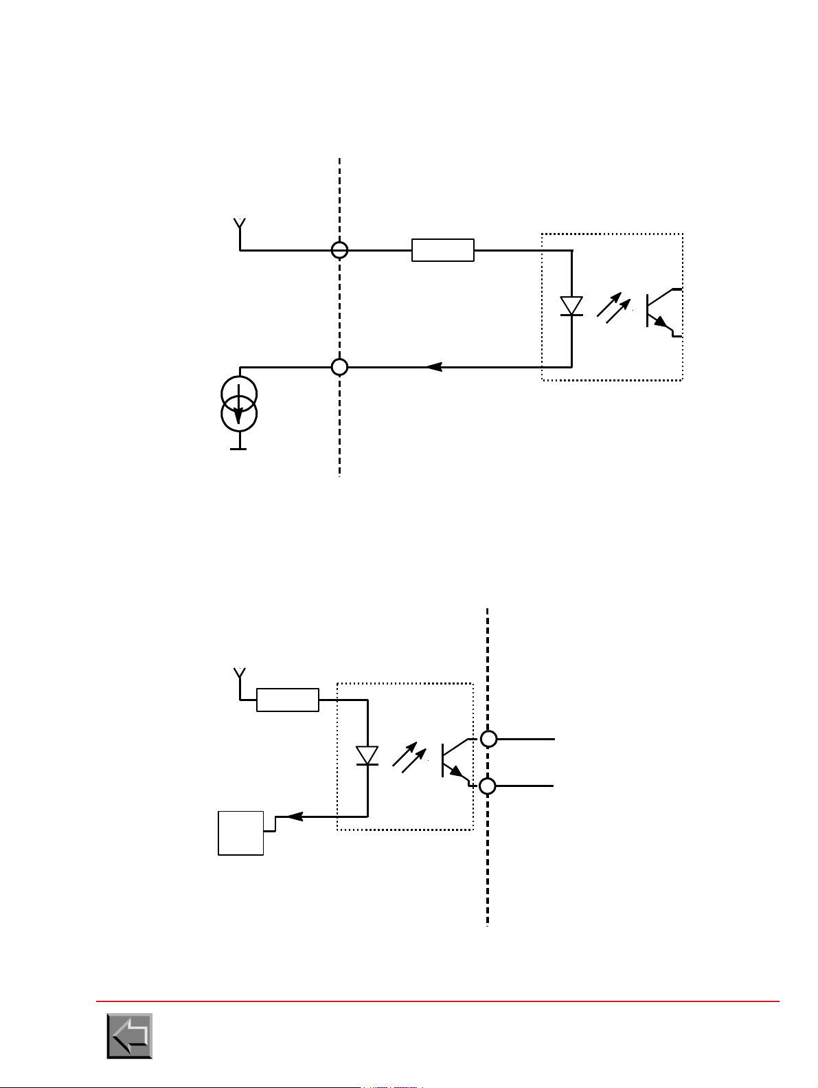
2. Current source
PRINTER
INTERFACE
EXTERNAL DEVICE
INTERFACE
+
-
-
Source I
Courrent
R
I
+12V
0V
0 ohms < R < 400 ohms
PRINTER
INTERFACE
EXTERNAL DEVICE
INTERFACE
+
-
R
I
+5V
7407
MCT6
I maxi = 2 mA
"0": I = 10 mA
"1": I = 0 mA
Site preparation manual
VARYPRESS 200
3. Opto Isolated ouput
"0": I = 10 mA
"1": I = 0 mA
Go to "Table of contents"
3-9
Page 72
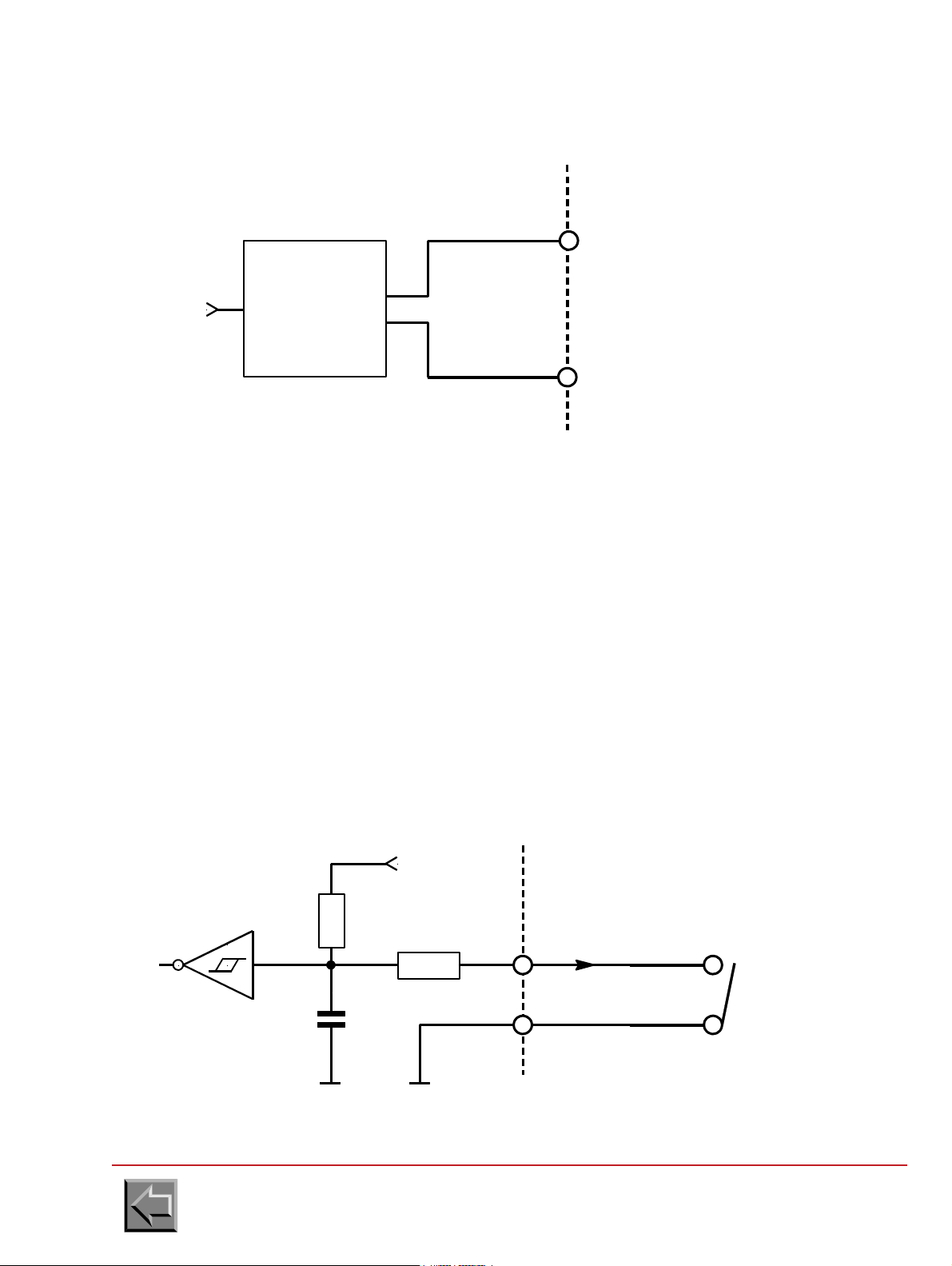
4. Differential serial output
PRINTER
INTERFACE
EXTERNAL DEVICE
INTERFACE
+
TX
RXD_H
RXD_L
+
-
Line
driver
3487
-
PRINTER
INTERFACE
EXTERNAL DEVICE
INTERFACE
+
-
100
I
+5V
470
+
-
2.2microF
0V 0V
74HC14
Site preparation manual
VARYPRESS 200
3.4.2 Signals from the external device to the printer
The input signal interface can be adapted to the printer interface in 3 different input types:
-Switch
- Opto Isolator
-Differential
Each input contains 2 pins marked +,- designed to adapt Pre/Post-processing interface to printer
interface.
NOTE: TXD_H ,TXD_L are differential inputs only.
1. Switch
"0": switch closed
"1": switch opened
Go to "Table of contents"
3-10
Page 73

2. Opto isolated input
PRINTER
INTERFACE
EXTERNAL DEVICE
INTERFACE
+
-
100
I
+5V
470
+
-
2.2microF
0V 0V
74HC14
PRINTER
INTERFACE
EXTERNAL DEVICE
INTERFACE
+
RX
TXD_H
+
-
Line
receiver
3486
-
TXD_L
"0": I = 10 mA
"1": I = 0 mA
Site preparation manual
VARYPRESS 200
3. Differential serial input
Go to "Table of contents"
3-11
Page 74

Site preparation manual
Ring connector
for M4 screw
cable
0
Printer speed
time
90 m/min or
max. speed
Maximum
speeding up:
0,6 m/s
2
Maximum
slow down:
0,5 m/s
2
VARYPRESS 200
3.5 CABLES
NOTE: In all cases the cables are supplied with the Pre/Post Processor equipment.
3.5.1 Cable between printer and pre/post processor devices
Connection have to be established by means of a shielded cable and two connectors witch metallic
cover. The shielding of the cable must be connected to either connector' s cover.
3.5.2 Common earth connection
The connection between the Pre / Post processor devices and the printer needs to be secured by a
cable to 10 mm2 cross section area.
On the printer side the connection is made by a ring connector and a M4 size screw in the place
specially provided for.
3.6 TIMINGS
3.6.1 Timing of the printer speed change
Go to "Table of contents"
3-12
Page 75
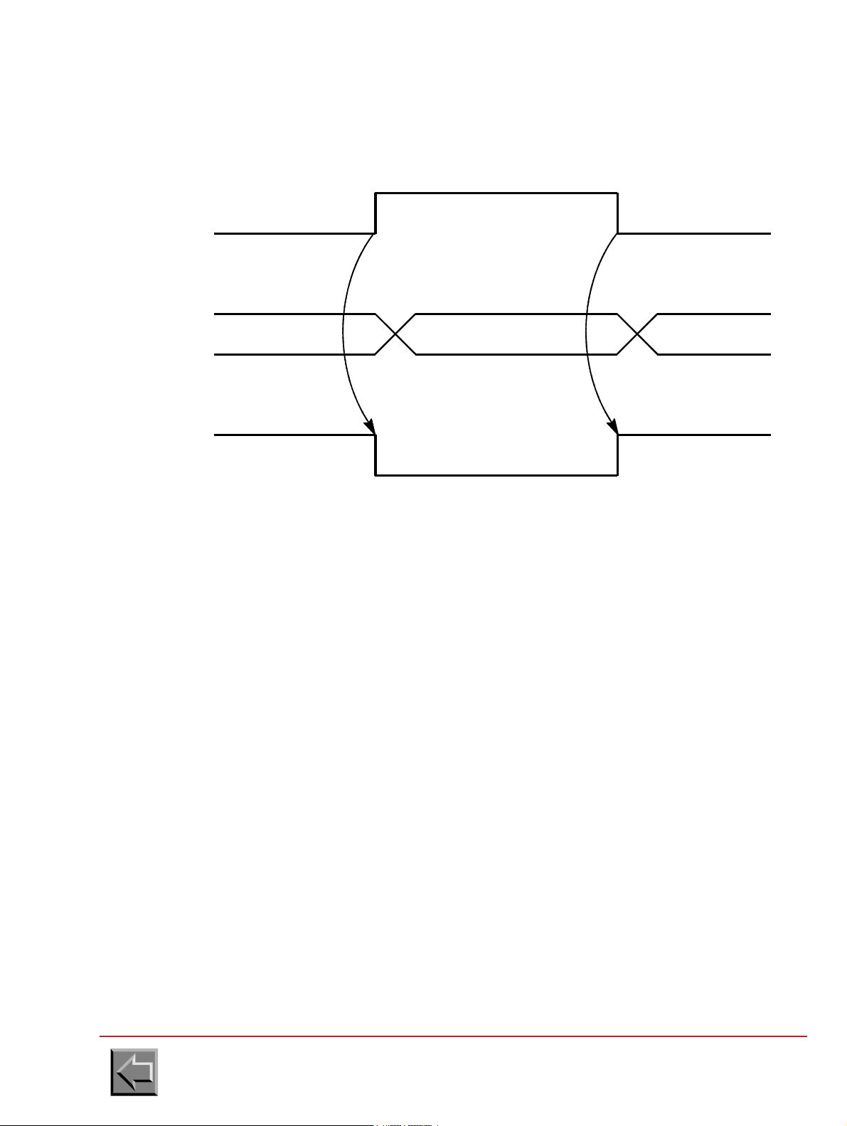
3.6.2 start/stop signal steps
S/S
PRINTER
STATUS
WAITING PRINTING WAITING
Stop Stop
Wait incident Wait incidentnot wait incident
Start
Site preparation manual
VARYPRESS 200
In case S/S = "0L" (stop) a "wait" incident will be displayed on the panel as "PRE/POST
PROCESSING STOP" and it will prevent any start command from the printer keyboard.
If the operator presses "START" on the pre/post-processing panel, the S/S signal will change to
"1L" and the "wait" incident will disappeared.
If the printer is "READY" and if the data is present to be printed, the printer will start. If not, it will
remain in a "WAITING FOR DATA" or "INCIDENT" status.
Go to "Table of contents"
3-13
Page 76

Site preparation manual
F
3.7 REQUIREMENTS
3.7.1 Using a pre processor device
- During a stoppage caused by pre-post processing, the printer does not stop immediately but
finishes printing the current page.
For this reason the printer cannot work with "taut paper" between the Pre- Processor Device
and the Paper Input to the Printer.
Therefore to avoid rupture of the paper, it is imperative to have a loop of paper not less than
a sheet height + 200 mm.
Example : If Paper Height =17 inches
Loop length = (17 x 25.4) + 200 = 632 mm
- The tension "F" exercised by the Pre Processor device on the paper at the input of the printer
must not exceed 5 Newtons.
VARYPRESS 200
Go to "Table of contents"
3-14
Page 77

Site preparation manual
F
VARYPRESS 200
3.7.2 Using a post processor device
- The Post-Processing Device must be capable to handle a backward paper movement of
maximum 150 mm equal to that of printer.
- The tension "F" exercised by the Post Processor device on the paper at the output of the
printer must not exceed 5 Newtons.
3.7.3 Using a post processor device with a printer in S.E.D. mode
If the printer is used in S.E.D. mode (Single Engine Duplex), the paper output of the printer is on
the right side of the printer of the forward paper movement. So the post processor will have to be
adapted in this case.
Go to "Table of contents"
3-15
Page 78

Site preparation manual
VARYPRESS 200
Go to "Table of contents"
3-16
Page 79

4. ST20
1650
1130
850
Unpacking sheet
4.1 PRODUCT PACKING
The stacker and the box with the accessories are fixed on a pallet and protected with a cover. They
are surrounded with a sleeve placed on the pallet. The unit is covered with a top, and steel strips are
used fasten the parts together.
The dimensions of the packed unit are: width 850 mm, depth 1130 mm and height 1650 mm.
The weight (including packaging) is 250 kg.
The unpacking sheet is attached inside the packaging.
Site preparation manual
VARYPRESS 200
NOTE: To unpack the unit, without damaging the sleeve, requires a free height of 3.20 m
between the floor and the ceiling is required.
Rear clearance of 2 m to take the unit off the pallet is required.
A working area of 1 m is also required around the packaging.
Go to "Table of contents"
4-1
Page 80
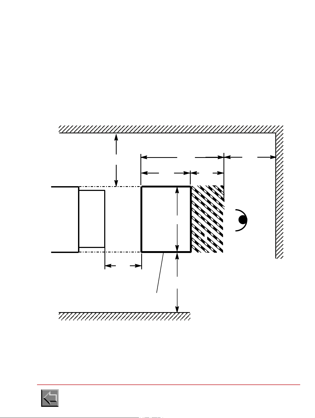
Site preparation manual
ST20
1250
650 600
880
1000
500
PRINTER
Paper loop formation
area (between 400 and
800 mm)
Access areas for the logical cabinets.
The rear panels can be taken off.
700
black adhesive bands spaced
Operator
PLAN VIEW
Stick onto the floor yellow and
50 mm apart (47286537-001)
Plate clearance area
VARYPRESS 200
4.2 PHYSICAL SPECIFICATIONS
Depth: 880 mm
Length: 650 mm (hors capteur boucle)
Height: 1420 mm
Weight: 193 kg
Floor loading: 10 kg/m
Floor characteristics: Standard computer room raised floor.
2
4.2.1 Standard ST20 stacker dimensions and clearance areas
Go to "Table of contents"
4-2
Page 81

ST20
black adhesive bands spaced
Stick onto the floor yellow and
50 mm apart (47286537-001)
Plate clearance area
1000
700
1250
PRINTER
1400
1000
Operator
Access areas for the logical
The rear panels can be taken off.
cabinets.
PLAN VIEW
880
Site preparation manual
VARYPRESS 200
4.2.2 Dimensions and clearance areas of ST20 90°
Note: This stacker can be placed at a 90° angle, either forward, or backward printer.
Go to "Table of contents"
4-3
Page 82

4.2.3 Raised floor cutouts
880
650
600
PLAN VIEW
70 40
40
70
70
2x
4x
Stacker plate in extracted
position to unload paper
Casters to move the unit
stacker immobilizing feet
Floor cutout to feed the
power supply and interface
cables through
Operator
97
Ø 75
Ø 75
Site preparation manual
VARYPRESS 200
Go to "Table of contents"
4-4
Page 83

Site preparation manual
VARYPRESS 200
4.3 ELECTRICAL SPECIFICATIONS
4.3.1 Mains voltage supplies
a. 230 V - 50 Hz
Voltage tolerance: +10 %, -10 %
Frequency tolerance: +
Single phase
Three wire cable: phase, neutral and earth
Power consomption: 220 VA
Current: 1 A
b. 120 V - 60 Hz
Voltage tolerance: +10 %, -13,5 %
Frequency tolerance: +
Single phase
Three wire cable: phase, neutral and earth
Power consomption: 220 VA
Current: 2 A
0.5 Hz
0.5 Hz
4.3.2 Mains connection
The unit is connected to the mains using a cable with 3 pin plug, plugged into the IEC mains socket
on the unit's power supply assembly.
The mains connection cable is supplied with the stacker.
4.3.3 Main switch
The main switch of the stacker is protected by two T2.5 Amp fuses.
4.4 AMBIENT OPERATING CONDITIONS
Temperature: 15 ºC to 30 ºC.
Relative humidity: 30 % to 70 %.
Atmospheric pressure: 562 to 780 mm Hg.
Go to "Table of contents"
4-5
Page 84

Site preparation manual
4.5 INTERFACE SPECIFICATION
4.5.1 Interface connector
The ST20 interface connector is of the SUB-D 37 channel, Female type.
Pin assignments of the connector:
Signal name Location Direction
TXD_H Pin 1 output
RXD_H Pin 2 input
STVITRD+ Pin 3 output (not used)
STPRT+ Pin 4 output
NTPI+ Pin 5 input
SDP+ Pin 6 input
not used Pin 7
not used Pin 8
STCNT+ Pin 9 output
STMA+ Pin 10 output
MVP+ Pin 11 input (not used)
not used Pin 12
not used Pin 13
STDMAR+ Pin 14 output (not used)
STDARR+ Pin 15 output (not used)
not used Pin 16
not used Pin 17
not used Pin 18
not used Pin 19
TXD_L Pin 20 Pin 1 feedback
RXD_L Pin 21 Pin 2 feedback
STVITRD- Pin 22 Pin 3 feedback (not used)
STPRT- Pin 23 Pin 4 feedback
NTPI- Pin 24 Pin 5 feedback
SDP- Pin 25 Pin 6 feedback
not used Pin 26
not used Pin 27
STCNT- Pin 28 Pin 9 feedback
STMA- Pin 29 Pin 10 feedback
MVP- Pin 30 Pin 11 feedback
not used Pin 31
not used Pin 32
STDMAR- Pin 33 Pin 14 feedback (not used)
STDARR- Pin 34 Pin 15 feedback (not used)
not used Pin 35
not used Pin 36
not used Pin 37
VARYPRESS 200
Go to "Table of contents"
4-6
Page 85

4.5.2 Identification
1/6"
The specification defines the data interexchange protocol and the Hardware interfacing between the
ST20 stacker and the printer.
Since the ST20 stacker is considered to be a post-processing system, the specification is linked with
the following specification:
SPECIFICATION Nº 47285168 "PRE/POST PROCESSING PRINTER INTERFACE"
4.5.3 Inputs
1/6 inch pulse signal (NTPI + , NTPI-)
Since the printer generates a positive pulse for a paper movement of 1/6 inch, this signal is
used by the ST20 to set the paper loop.
The ratio between the upper and lower level must be 50%.
Site preparation manual
VARYPRESS 200
- Direction of paper movement (SDP+, SDP-)
This signal is used to inform the ST20 in which direction the paper moves in order that it may
manage the forward or backward movement of the paper.
"0": Paper forward
"1": Paper backward
Paper movement (MVP+, MVP-)
This signal received by the ST20 indicates that the printer will start printing. It is activated
approximately 2 seconds before printing. This anticipation time is valid only during paper
scrolling.
"0" paper movement
"1" no paper movement
NOTE: this signal is used by the ST20 only.
Serial link (RXD-H, RXD1-L)
The ST20 receives information from the printer via a serial link in differential mode. This serial
link is of the RS 422 type.
Commands received:
- Link test dialogue
(enabling the establishment of a serial link between the printer and the ST20)
- Paper parameter dialogue
(enabling the transmission of the form height from the printer to the ST20)
cf specification Nº 47287014 "Pre-post processing orders/status interface
IMPORTANT: This is valid only when the ST20 is connected to the NIPSON printer.
Go to "Table of contents"
4-7
Page 86

4.5.4 Outputs
1L
0L
500ms < T < 1s
T
Stacker connected (STCNT+, STCNT-)
Informs the printer that the ST20 is present (but not necessarily ready!).
This may possibly enable the printer to totally or partially invalidate its internal stacker.
Stacker ready (STPRT+, STPRT-)
Informs the printer that the ST20 system is ready. This signal also acts as an emergency stop
signal (Hard stop).
Stacker speed reduced (STVITRD+, STVITRD-)
This signal emitted by the stacker may request that the printer speed be reduced.
Site preparation manual
VARYPRESS 200
"0": connected
"1": not connected
"0": ready
"1": not ready
"0": Speed reduction
"1": No speed reduction
NOTE: This signal is not yet generated by the ST20
Printer ON/OFF through the ST20 (STMA+, STMA-)
This signal emitted by the ST20 requests that the printer be turned on or off ( Soft stop)
"0": off
"1": on
NOTE- this signal is used when the STDMAR+, STDMAR-, STDARR+,STDARR- signals are
not used.
Printer ON request by the ST20 (STDMAR+, STDMAR-)
This signal emitted by the ST20 may request that the printer be turned on.
"0": printer on request
"1": no printer on request
NOTA:-This signal is used with STDARR+ STDARR- when the STMA+, STMA- signals
are not used.
- This signal is not yet generated by the ST20.
Go to "Table of contents"
4-8
Page 87

Site preparation manual
1L
0L
500ms < T < 1s
T
VARYPRESS 200
Printer OFF request by the ST20 (STDARR+ , STDARR- )
This signal emitted by the ST20 may request that the printer be turned off.
"0": turn off request
"1": no turn off request
NOTE:- This signal is used with STDMAR+ STDMAR- when the STMA+,STMA- signal
is not used.
- This signal is not yet generated by the ST20
Serial link 1 (TXD1_H ,TXD1_L)
The ST20 may transmit information to the printer via a serial link in differential mode. This
serial link is of the RS422 type.
commands sent :
- Response to the liaison test dialogue
(enabling the validation of the serial link between the printer and the ST20 )
- Response to the paper parameters dialogue
(enabling the acknowledgement of the form height received by the ST20)
cf. SPECIFICATION nº 47287014
PRE-POSTPROCESSINGORDERS/STATUSINTERFACE"
IMPORTANT: This is valid only when the ST20 is connected to the NIPSON printer.
Go to "Table of contents"
4-9
Page 88

Site preparation manual
ST20
INTERFACE
EXTERNAL SYSTEM
INTERFACE
+5V
MCT6
“0" : I = 10 mA
“1" : I = 0 mA
+
-
I
7407
ST20
INTERFACE
EXTERNAL SYSTEM
INTERFACE
RXD_H
RXD_L
Line
emitter
3486
TX
+
-
VARYPRESS 200
4.5.5 Electric specification of the signals
Output signals:
The signal interface is of the opto coupler type. Each output has 2 terminals referenced +,which enable the adaptation of the interface between the printer and the ST20.
NOTE : The serial link output signal is in differential mode.
Opto Coupler output
serial link output
Go to "Table of contents"
4-10
Page 89
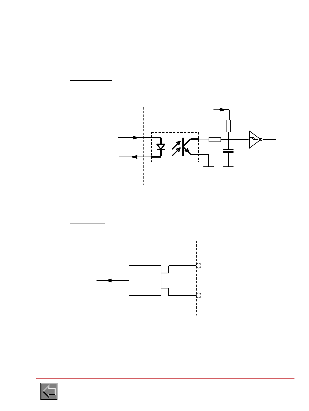
Site preparation manual
+5V
74HC14
470
100
+
-
0V
MCT6
“0" : I = 10 mA
“1" : I = 0 mA
+
-
I
2.2 mF
0V
ST20
INTERFACE
EXTERNAL SYSTEM
INTERFACE
ST20
INTERFACE
EXTERNAL SYSTEM
INTERFACE
RXD_H
RXD_L
Line
emitter
3486
TX
+
-
VARYPRESS 200
Input signals
The signal interface is of the input by opto coupler type. Each input has 2 terminals
referenced +,- that enables the adaptation of the interface between the printer and the ST20.
NOTE : The serial link input signal is in differential mode.
Opto coupler input
Serial link input
Go to "Table of contents"
4-11
Page 90

4.5.6 Cables
Cable
Terminal for the M4 screw
ST20 / PRINTER interface link cable
The link must be made by a shielded cable with two connectors with metallic housing. The
shielding of the cable must be repeated for the housing of each connector.
Equipotential earthing link
The link between the ST20 stacker and the printer must be established by a cable with a
gauge of 8 or 10 mm2 cross-section. At the ST20 stacker, the cable must be fastened by a M4
screw and a terminal at the place provided for it.
Site preparation manual
VARYPRESS 200
NOTE: The cables are always supplied with the ST20 Stacker.
Go to "Table of contents"
4-12
Page 91

Site preparation manual
VARYPRESS 200
5. Page printer implementation plan
This checklist provides the planning coordinator with the major activities and tasks that must be
performed before and during installation of the NIPSON printer.
Activities before delivery:
- Order the NIPSON printer.
- Order the supplies for the NIPSON printer.
- Determine and then order the licensed programs for the NIPSON printer.
- Identify applications for migration to NIPSON printer.
- Prepare a physical layout for NIPSON printer.
- Prepare The moving of the NIPSON printer from the lorry to the computer room.
- Prepare the electrical wiring and outlets.
- Receive the supplies for the NIPSON printer.
Activities since arrival of the printer:
- Assist the customer engineer in configuring the NIPSON printer.
- Assist the customer engineer with the performance of the complete test of the NIPSON printer
and the channel attachment.
- Have printer operator(s) available for training at installation time.
Go to "Table of contents"
5-1
Page 92

Site preparation manual
VARYPRESS 200
SITE PREPARATION SUMMARY
BEFORE DELIVERING THE NIPSON PRINTER
Dimensions
- Plan the surfaces required for installation..............................................................
- Plan the machine connections...............................................................................
- Plan the cutouts in the false bottom.......................................................................
- Plan the installation of the pre/post-processing equipment ...................................
- Strengthen the false bottom, if necessary .............................................................
Electrical installation
- 50 Hz 400 V ........................................................................................................
- 60 Hz 400 V ........................................................................................................
- Precautions to be taken for the machine leakage current .....................................
- IT or TT or TN wiring diagram................................................................................
- Customer's main switch 50 Hz : 50 A........................................................
- 60 Hz : 80 A........................................................
- Customer's differential circuit breaker....................................................................
- 60 Hz power supply wiring to be planned ..............................................................
Interfaces
- Interface type: ETHERNET ........................................................
- IPDS ...................................................................
-
- Lengths of cables, types of connectors .................................................................
Unpacking the machine
- Unloading the lorry: Easy access .......................................................
- Presence of loading bay .....................................
- Handling vehicle .................................................
- Unpacking in the interior of a building....................................................................
- Unpacking on the outside of a building..................................................................
- Handling vehicle ....................................................................................................
Moving the machine
- Presence of stairs ..................................................................................................
- Presence of access ramps ....................................................................................
- Width of corridors: Greater than 1.20 m ...........................................
- Floor: "Hard" possibility of moving the machine on its castors ...............
- "Soft" move the machine with a pallet truck .................................
- Lift: Dimensions ..................................................................................
- Entry into the lift cage - prepare a steel plate to roll over .............
Go to "Table of contents"
5-2
Page 93

NOM / NAME:
Vos remarques sur ce document / Technical publications remarks form
Titre / Title :
N° Référence :
Reference No.:
ERREURS DETECTEES / ERRORS IN PUBLICATION
AMELIORATIONS SUGGEREES / SUGGESTIONS FOR IMPROVEMENT TO PUBLICATION
Vos remarques et suggestions seront attentivement examinées.
Si vous désirez une réponse écrite, veuillez indiquer ci-dessous votre adresse postale complète.
Your comments will be promptly investigated by qualified technicial personnel and action will be taken as required.
If you require a written reply, furnish your complete mailing address below.
SOCIETE / COMPANY:
ADRESSE / ADDRESS:
DATE:
Remettez cet imprimé à un responsable de NIPSON ou renvoyez le à l’adresse ci-dessous.
Please give this technical publications remarks form to your NIPSON representative or mail to address below.
Site Preparation, VARYPRESS 200
22 A1 13NS REV5
NIPSON SAS
28, rue E. Thierry-Mieg - BP 257 - 90005 Belfort Cedex - France
Tel.: +33 (0)3 84 54 50 00 - Fax: +33 (0)3 84 54 52 18
http:/www.nipson.com - e-mail: info@nipson.com
Page 94

 Loading...