

Page 1
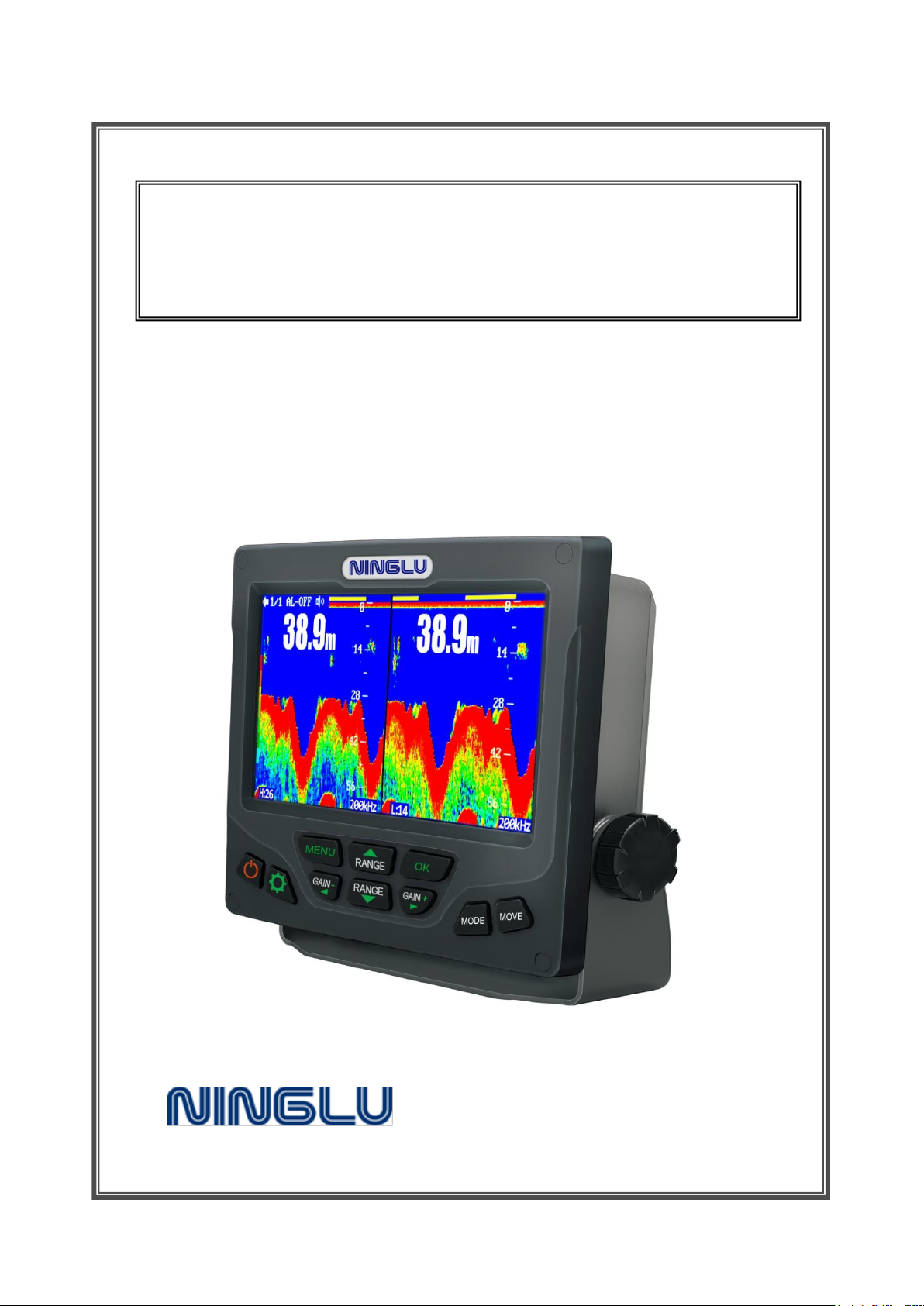
7-inch Dual-channel
Navigation Sounder
DS302
Operation & Installation Manual
Document: NLT-DS302-SSEN
Edition: V130815
1
Page 2

Contents
Working Principle ....................................................................................... 3
Working Principle of the Sounder .......................................................... 3
Screen Display ........................................................................................ 3
Introduction ................................................................................................. 4
Screen ...................................................................................................... 4
Operation ..................................................................................................... 5
Keyboard.................................................................................................. 5
Power ON/OFF ................................................................................... 5
Brightness ................................................................ ......................... 5
GAIN ................................................................................................... 5
RANGE ............................................................................................... 5
MODE ................................................................................................. 5
MOVE ................................................................................................. 5
MENU ................................................................................................. 5
Operation ..................................................................................................... 6
Installation ................................................................................................... 7
Host installation ................................................................ ...................... 7
Considerations ........................................................................................ 7
Installation ................................................................................................... 8
Transducer installation ........................................................................... 8
Connection .............................................................................................. 8
Technical Parameters ................................................................................. 9
2
Page 3
Worki n g Principle
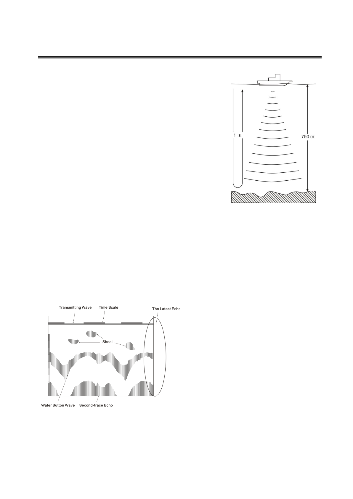
The acoustic velocity is 340m/s in the air and 1,500m/s
in the water. The acoustic time is one second during the
round-trip distance of the underwater 750m. So, the
target depth can be calculated by measuring the
round-trip time of acoustic wave (Fig. 1).
Due to ultrasonic frequency is higher than that of the
sound waves by human-ear hearing, ultrasonic is
suitable for underwater detection. The ultrasonic
transducer of the sounder can launch and receives the
ultrasonic wave. Through recording, the underwater
target is displayed on the LCD screen and the water
depth is calculated for display.
The discontinuous yellow line is the
time scale of 30 seconds. Under the
time scale, the horizontal line is the
transmitting wave. Shown in Fig. 2, the
three spot may be the shoal. Under shoal,
there are the water-button wave and
second-trace echo, which depth is the
twice of the water-button wave depth. The
water button is harder, the echo is
stronger and thicker.
Fig. 1
Fig. 2
Working Principle of the Sounder
Screen Display
The ultrasonic wave is sent and received repeatedly by the sounder. The latest echo
is recorded as a line on the far right of the screen. The image is consisting of the
moving-to- left echo.
3
Page 4
Introduct ion
DS302 dual-channel echo sounder(200kHz & 200kHz) is of high sensitivity and
advanced detecting software which can display the water bottom landform, depth and
figures accurately. With 7 inch color TFT LCD screen of high resolution (480X234 Pixel), it
is easily operated and used for ship navigation.
The dual channel gain can be adjust independently and adapted to the unbalanced
conditions of two transducer signals of the fore and after ship. The auto range can also
choose to track the stable measuring channel. It can timely, accurately and steadily
measure and display the underwater topography, water depth and the object shape.
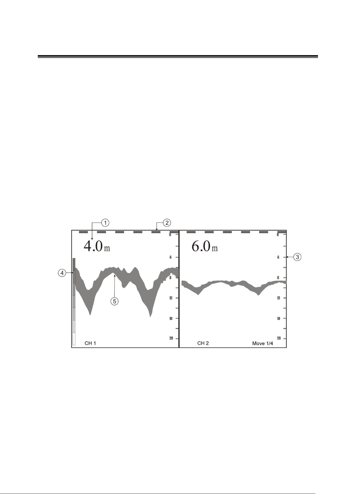
Screen
① Depth ② Time Scale(Send a 30-second yellow horizontal line each 30 seconds)
③ Basic Range ④ Color Code Level ⑤ Echo
4
Page 5
Opera tion
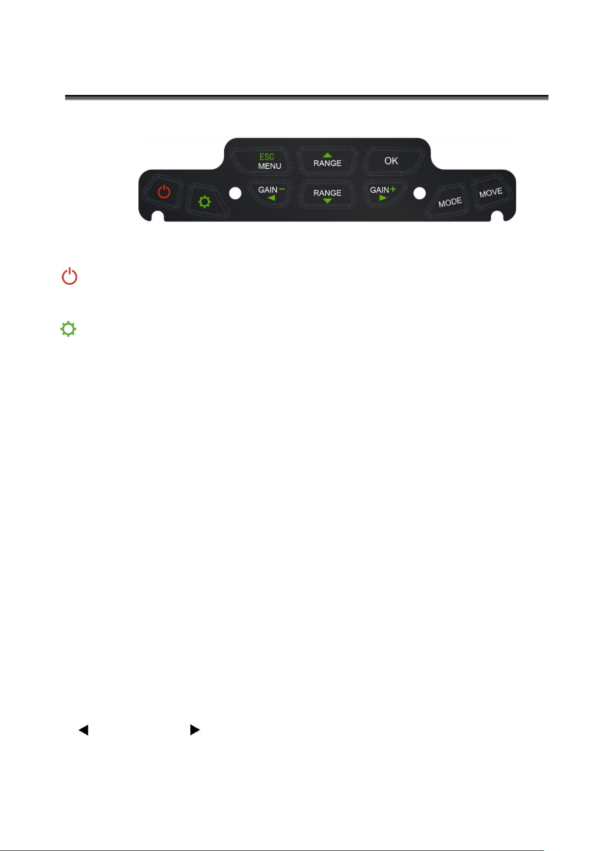
Keyboard
Power ON/OFF
Switch on/off the power supply
Brightness
Adjust the LCD brightness (LCD backlight)
GAIN
【Gain+】&【Gain-】
In single channel model,set gain by pressing【Gain+】&【Gain-】directly.
In dual channel model, using 【Menu】to adjust gain value.
RANGE
【Range▲】 & 【Range▼】
Press【Range▲】&【Range▼】directly to adjust basic depth range, while the Auto range is
off (set in Menu).
MODE
Press【MODE】 repeatedly to choose among three display model: Channel 1, Channel 2,
Dual-channel.
MOVE
The picture speed function is to set the screen frame rolling speed based on per ping of
transmission. Press【MOVE】 repeatedly to choose among speed:1/4、1/2、1/1、2/1、4/1.
MENU
Press【Menu】into menu.
【▲】: UP 【▼】: DOWN
【▲】: LEFT 【 - 】: RIGHT
5
Page 6
Opera tion
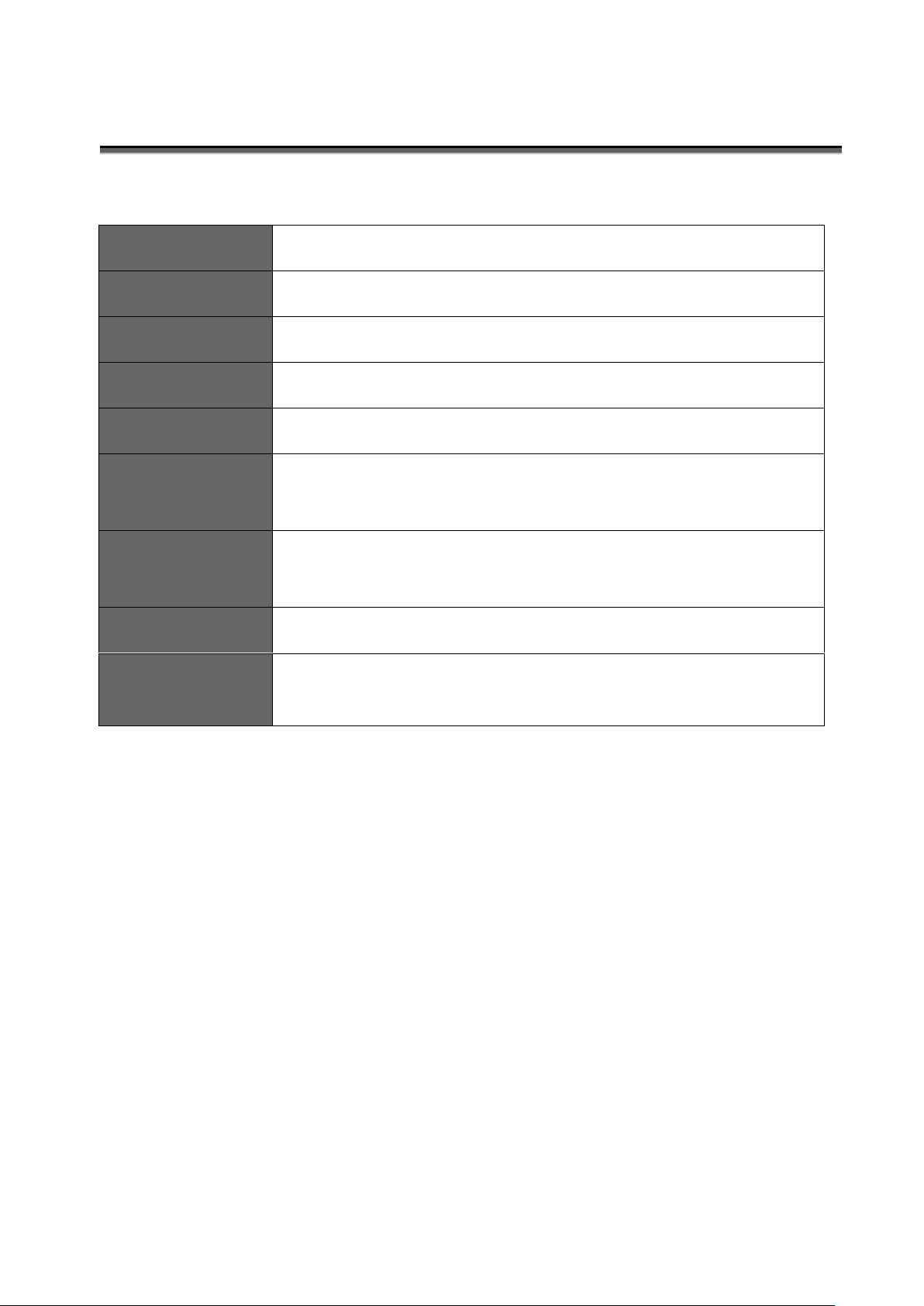
GAIN_1
Gain for channel 1:01-20
GAIN_2
Gain for channel 2:01-20
Alarm
Set alarm depth: OFF/0.4-10m
Buzzer
Turn on/off the alarm buzzer
Echo LEVEL
Set echo colors: 3-8
Auto Range
Auto range:OFF, Track 1 (channel 1), Track 2 (channel 2)
When auto range is on, range cannot be adjusted manually.
Output
Power
Power output:BIG/SMALL
Background
Set background color:Blue/Black
Press[OK]
to quit
Save all setting and quit form menu
6
Page 7
Instal l ation
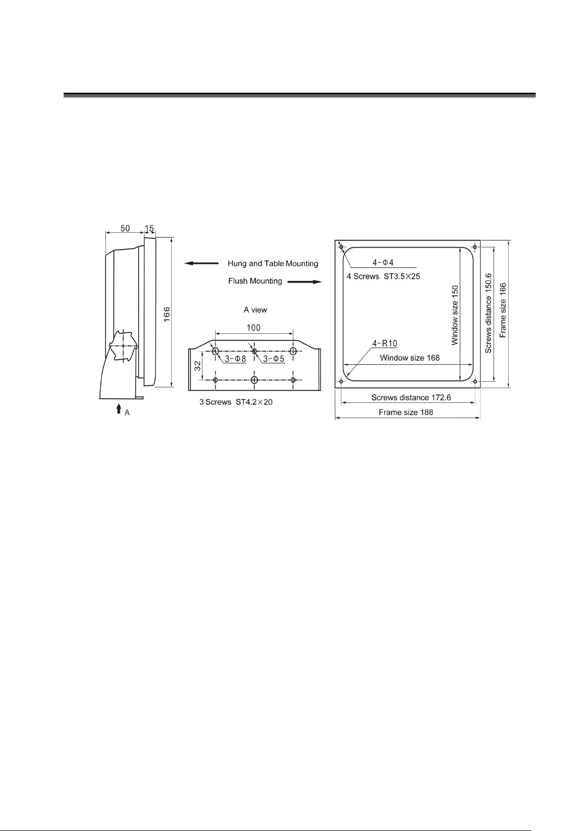
Unit: mm
Host installation
The host installation can be in the type of Hung、Table and Flush.
Considerations
1. The instrument should avoid direct sunlight, shock and vibration.
2. The24 v regulated power supply should be used to avoid burning machine.
3. Main instruments should be far away from the equipment with electromagnetic radiation,
such as motor and generator.
7
Page 8
Instal l ation
Transducer installation
Transducer is a sophisticated front-end signal sensor. Its transport and installation should be
careful to avoid pressure, drop or working in the air and the surface cannot be attached by
paint or parasites.
The installation location of the transducer is very important, which directly influences the
measuring accuracy. Transducer shall be installed where the ship bottom is relatively flat
and away from the vibration zone, such as the propeller. And the surface should be
horizontal to ensure uniform water flow around transducer when navigating. And the
transducer shall not be surface or contact the vortex flow.
Dual channel sounder can be used as water depth monitoring at the front or rear of the ship.
When the bare ship fast forward, the prow will slightly raise, which may result in unstable
readings of the transducer. Please manually choose reading stable channels as automatic
range tracking target.
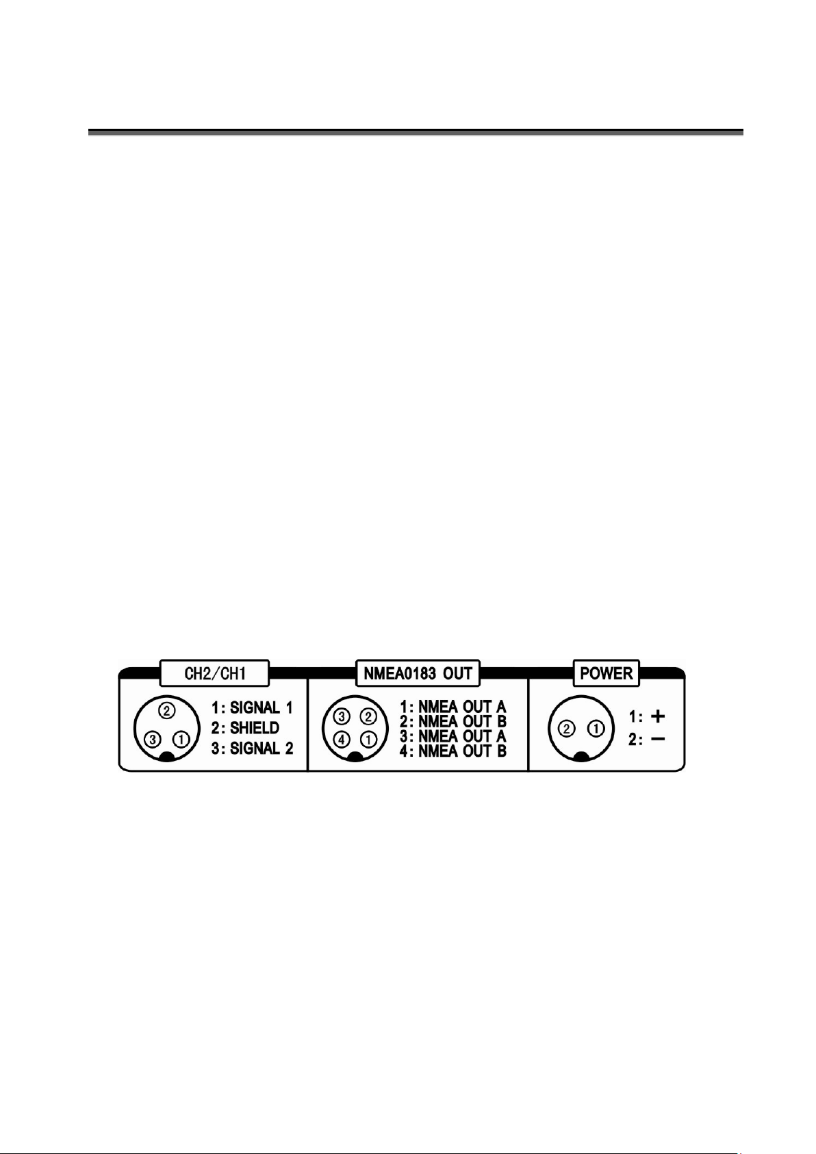
Connection
Transducer Interface NMEA Output Power Supply
CH1/CH2
8
Page 9
Tech n i c al Parameters
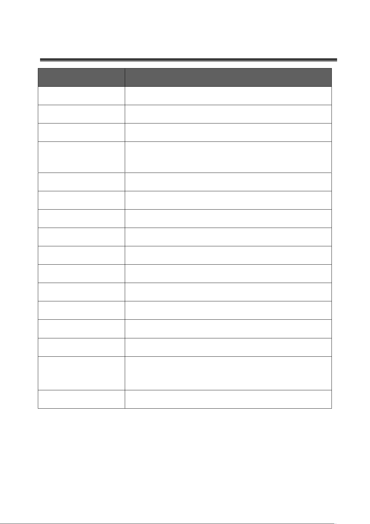
Item
Specification
Display
7 inch TFT LCD,480×234 pixel
Frequency
Dual-channel 200kHz
Range
2.5-200m
Min. depth
detectable
0.3m
Auto range
Select the auto range of tracing CH1/CH2
Output power
200kHz, 300W
Time Scale
30-second yellow time scale
Echo Levels
8 colors signal levels
Alarm Types
Shallow
Alarm Beeper
Buzzer(switch able),flashing
Power supply
DC24V(19~33V),20W
Temperature
0~50℃,IEC 60945
Water proof
IP52
Weight
1.5kg
size
Width 188mm、High 166mm、Depth 65mm
(Not include holder)
Installation
Hung、Flush (Window size 168×150mm)
9
 Loading...