

Page 1
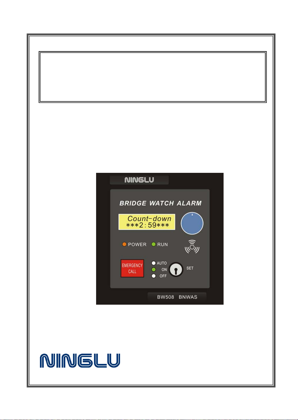
Bridge Navigational
Watch Alarm System
BW508
Operation & Inst allation Manual
Document: NLT-BW508-SSEN
Edition: V121225
Page 2

Contents
Foreword .......................................................................... 1
System description ............................................................. 2
Specification ...................................................................... 4
Setting ............................................................................. 5
Select dormant period (Td) ................................................ 5
Adjust buzzer characteristics of 1st Stage Alarm ..................... 5
Adjust buzzer’s volume of 1st Stage Alarm ............................ 6
Adjust time period of 2nd Stage Alarm .................................. 6
Adjust backlight of LCD and BW508R .................................. 7
Operational mode ............................................................... 8
Automatic ...................................................................... 8
Manual ON ..................................................................... 8
Manual OFF .................................................................... 8
Operation .......................................................................... 9
Dormant ........................................................................ 9
Visual indications ............................................................ 9
st
1
Stage Alarm ................................................................ 9
2nd Stage Alarm ............................................................. 10
3rd Stage Alarm ............................................................. 10
Reset .......................................................................... 11
Emergency call ............................................................. 11
Transfer of alarms ......................................................... 11
System output .............................................................. 12
Security ....................................................................... 12
Test ............................................................................... 13
Malfunctions .................................................................... 15
System Installation ........................................................... 16
Installation dimension .................................................... 16
System Diagrams .......................................................... 19
BW508 Internal Wiring Diagram ........................................ 20
BW508 External Wiring Diagram ....................................... 21
Page 3
Foreword
Bridge Navigational Watch Alarm System is to monitor the awareness of
the Officer of the Watch (OOW) and automatically alerts the Master or
another qualified OOW if for any reason the OOW becomes incapable of
performing the OOW's duties. This purpose is achieved by a series of
indications and alarms to alert first the OOW and, if he is not responding,
then to alert the Master or another qualified OOW. Additionally, BW508
also provide the OOW or other equipment with a means of emergency
calling for immediate assistance.
Time table
1
Page 4

System description
The whole Bridge Navigational Watch Alarm System consists of operating
device, connecting module, reset button, 1st Stage Alarm, 2nd Stage Alarm,
3rd Stage Alarm and AC adapter.
Operating device BW508MAIN
Display screen: 2*16 LCD
Internal buzzer: use for 1
st
Stage Alarm
Key switch S1: choose operational modes and setting
Rotary encoder S2: use for system’s setting and adjustment
Emergency call S3: use for emergency call’s trigger and reset
Power failure indicator L1: indic ate main power supply failure
Run normally indicator L2: indicate system run normally
Auto indicator: indicate system in auto mode
ON indicator: indicate system in manual on mode
OFF indicator: indicate system in manual off mode
Installation Location: bridge area
Installation mode: flush or vertical mounting
Connecting module BW508CONN
Installation Location: bridge area
Installation mode: TS35 rail mounting
2
Page 5

Reset button BW508R
Installation Location: bridge area
Installation mode: type A:flush mounting,type B:wall mounting
Number of installations: max.6
1st Stage Alarm BW508RA1
Installation Location: bridge wings
Installation mode: wall mounting
Number of installations: max.3
2nd Stage Alarm BW508A2
Installation Location: officer’s cabin area
Installation mode: type A:wall mounting,type B:flush mounting
Number of installations: max.4
3rd Stage Alarm BW508A3
Installation Location: officer’s corridor area
Installation mode: wall mounting
Number of installations: max.2
AC Adapter BW508ADPT
Installation Location: bridge area
Installation mode: wall mounting
3
Page 6

Specification
Operating temperature: - 5 ℃ ~ +55 ℃
Relative humidity : 93% + 2% (at 40±3℃)
Power supply: 24VDC (nominal)
Power consumption: less than 75W
Timings accuracy: less than 5 % or 5s
1st Stage Alarm tone: 8 kinds
1st Stage Alarm volume level: 75~85db/1m
2nd Stage Alarm volume level: 75~120db/1m
Degree of enclosure& safety distances to magnetic compass
degree of
Model type
enclosure
BW508MAIN IP20
BW508CONN IP00
BW508RA1 IP65 /
BW508R,A2,A3 IP20 /
Interfacing
Interfacing Name I/O Form
heading or track control system Input switching value
emergency call Input switching value
external reset devices Input switching value
status output Output ALR/ switching value
Safety distances to
magnetic compass
Standard 0.49m
Steering 0.35m
Standard 0.42m
Steering 0.37m
malfunction output Output switching value
4
Page 7
Setting
Select dormant period (Td)
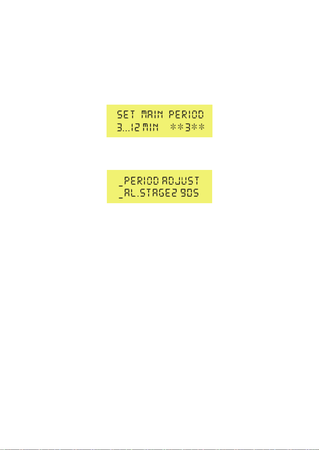
In case that authorized person (Master) demands to select other dormant
period, person has to turn key switch S1 on BW508MAIN to position
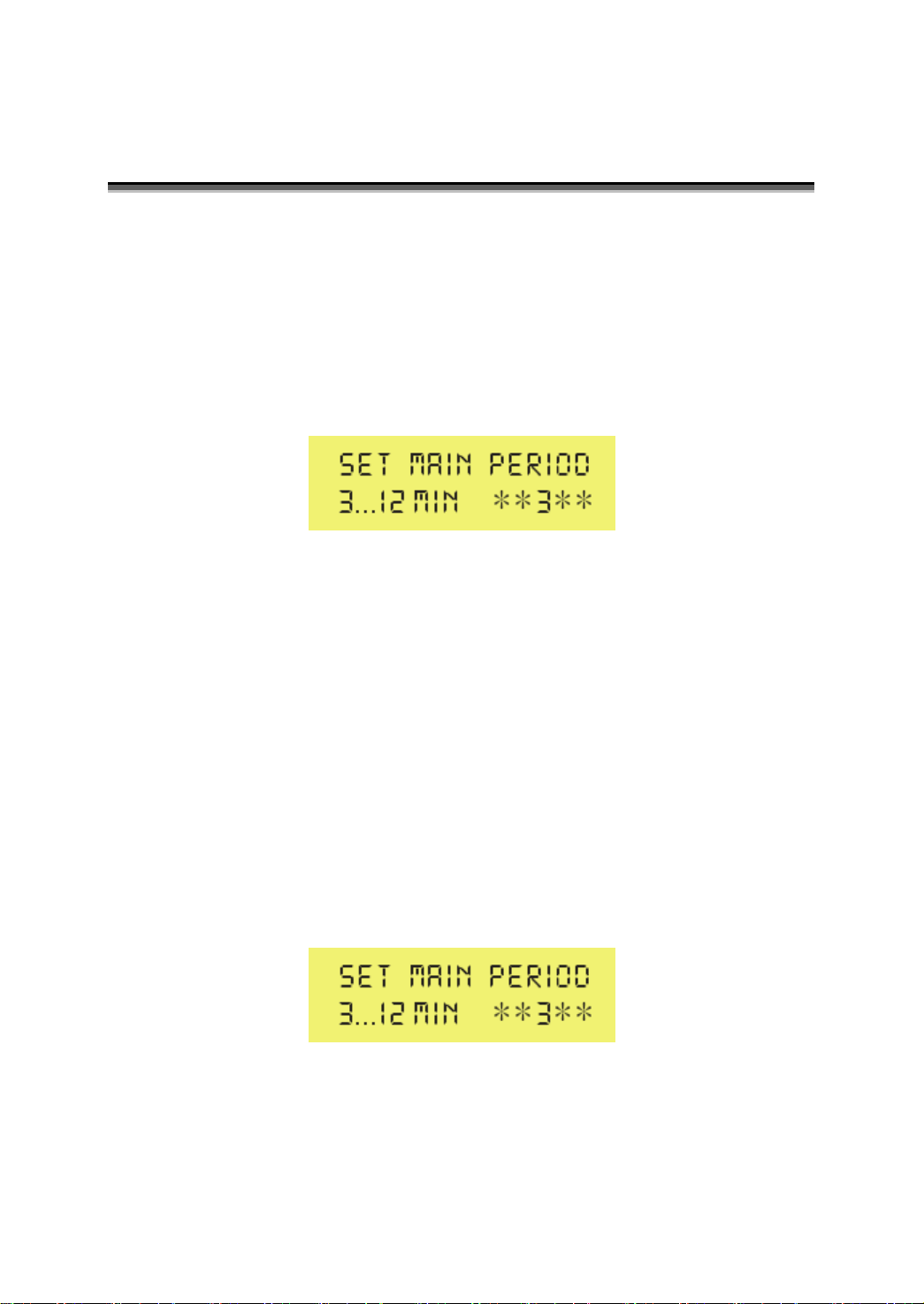
“SET”. In this position only dormant period can be chosen by using rotary
encoder S2. Display is showing as follow
By turning rotary encoder S2 in clock wise direction, value is increasing.
By tuning rotary encoder S2 in counter clock wise direction, value is
decreasing. Possible main period value is limited between 3 and 12 min.
Step width is 1 min. By turning key switch S1 into centre position, system
accepts new value.
Adjust buzzer characteristics of 1st Stage Alarm
1st Stage Alarm internal buzzer’s sound characteristics can be adjusted.
By turning key switch S1 on BW508MAIN to position “SET”. Display is
showing as follow
Now push rotary encoder S2 on operating device BW508MAIN
repeatedly till the display is showing as follow
5
Page 8
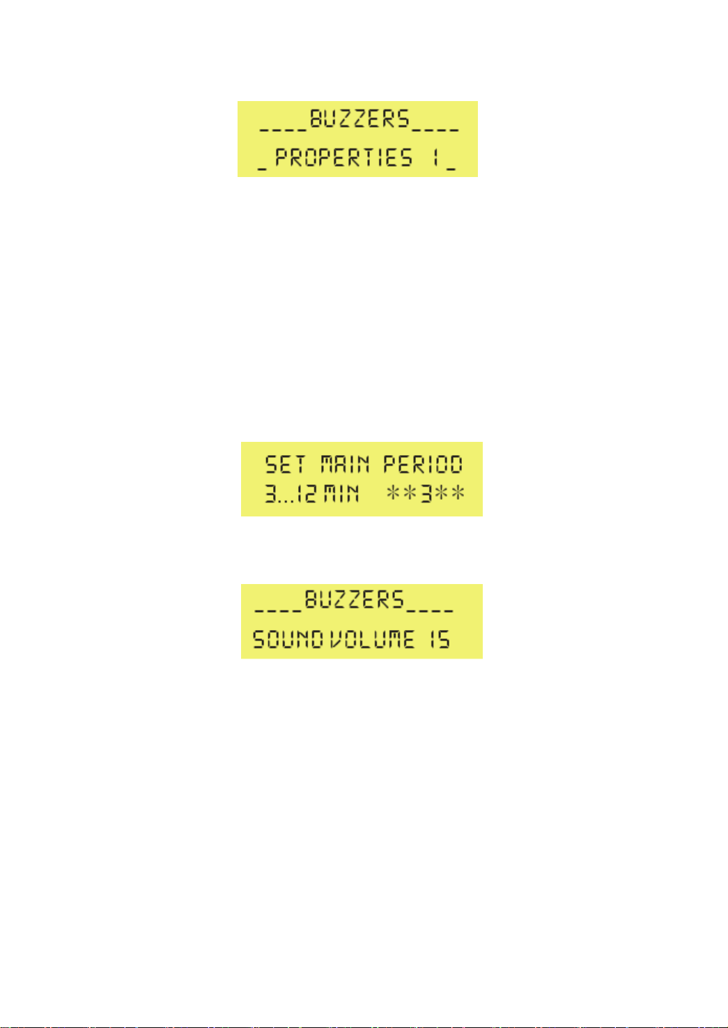
Now turn rotary encoder S2 to choose an adequate buzzer characteristic.
By pushing rotary encoder S2 display is changing and system accepts
adjusted value.
Adjust buzzer’s volume of 1st Stage Alarm
1st Stage Alarm internal buzzer’s sound volume (1~15) can be adjusted.
To adjust internal buzzer’s volume turn key switch S1 on BW508MAIN to
position “SET”. Display is showing as follow
Now push rotary encoder S2 on BW508MAIN repeatedly till the display is
showing as follow
Now turn rotary encoder S2 in counter clock wise direction to decrease
buzzer’s sound volume or in clock wise direction to increase sound
volume. By pushing rotary encoder S2 display is changing and system
accepts adjusted value.
Adjust time period of 2nd Stage Alarm
Adjustment could be necessary due to large vessel. Period can be
adjusted to max. 180sec (default value is 90sec), to allow sufficient time
6
Page 9
for back-up officer and/or Master to reach bridge area before watch alarm
system is triggering 3
rd
Stage Alarm .
To adjust a.m. time period turn key switch S1 on BW508MAIN to position
“SET”. Display is showing as follow
Now push rotary encoder S2 on BW508MAIN repeatedly till the display is
showing as follow
Now turn rotary encoder in clockwise direction to increase time period
value or in counter- clock wise direction to decrease time period value.
System allows only value between 90 and 180sec. By pushing rotary
encoder S2 display is changing and system accepts adjusted value.
Adjust backlight of LCD and BW508R
If you want to adjust backlight of LCD and BW508R .Please turn rotary
encoder in clockwise direction to brighten, in counter- clock wise
direction to dim.
7
Page 10
Operational mode
Automatic
System can be switched on by external systems (ship's heading or track
control system)
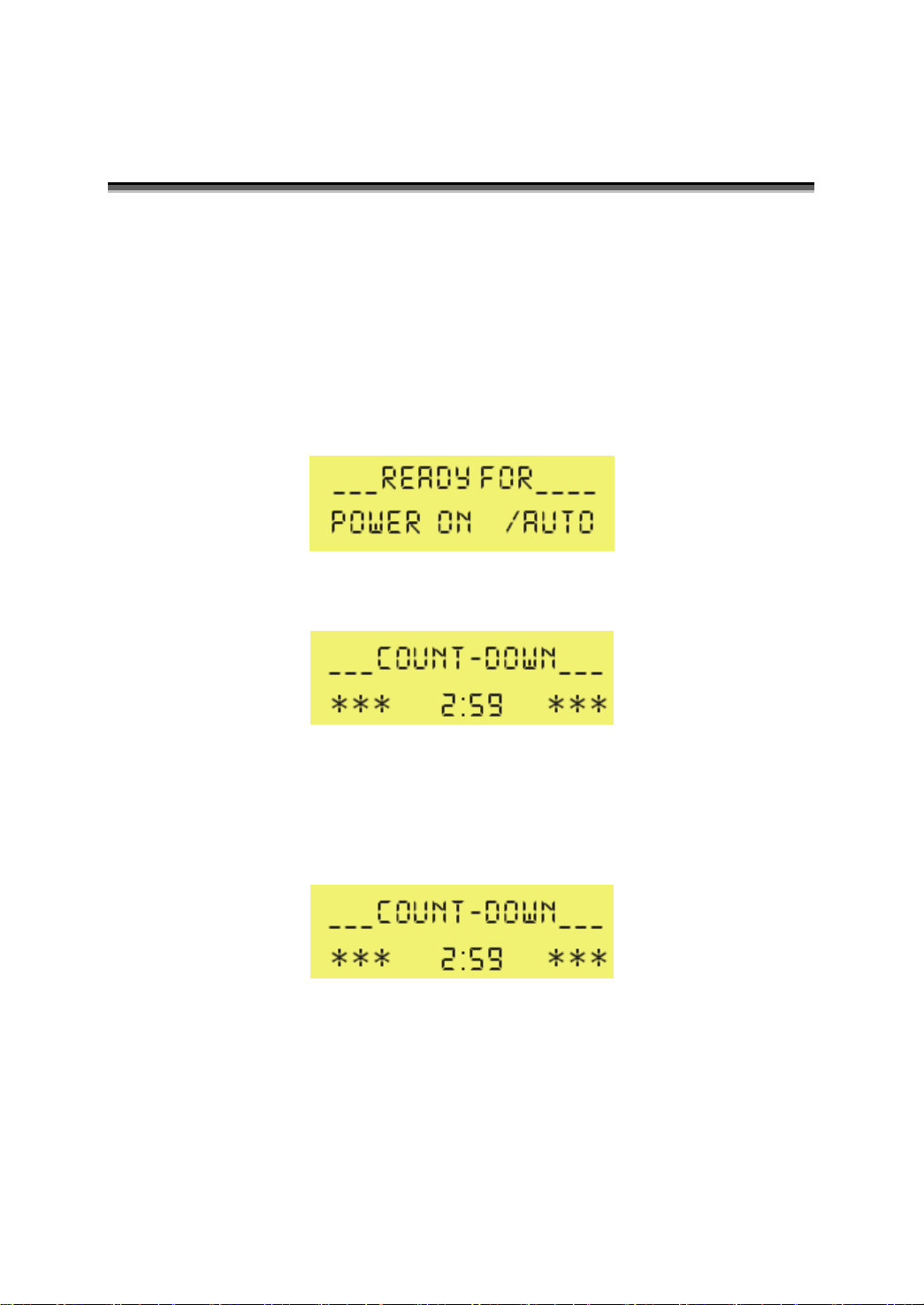
By turning key switch S1 left once. System is in AUTO mode. Auto
indicator is on. Display is showing as follow.
When ship's heading or track control system is activated, system’s
running is triggered. Count-down is active as shown on display as follow.
Manual ON
Authorized person (Master) switches on system by turning key switch S1
left twice. Count-down is active as shown on display as follow.
Manual OFF
Master is able to shut down system by turning key switch S2 left for longer
than 2 sec .
8
Page 11
Operation
Dormant
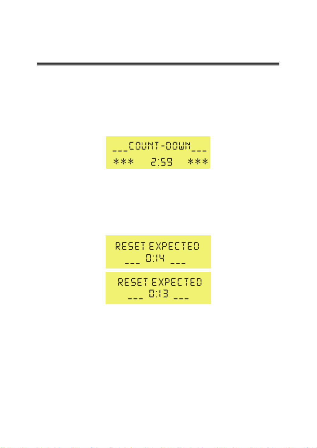
Turn the key to choose the operational mode. After system running is
trigged. Dormant (main) period count-down is active as shown on display
as follow.
Visual indications
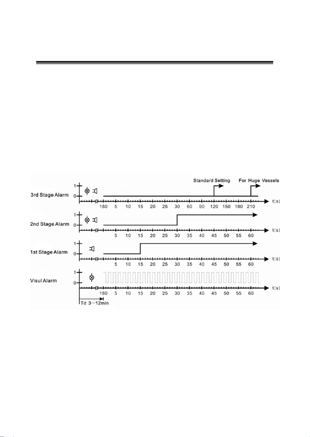
If dormant period (Td) is over without OOW’s reset, system activates all
illuminated reset units by 1Hz flash light. Display is showing in 1Hz toggle
mode display
st
1
St age Alarm
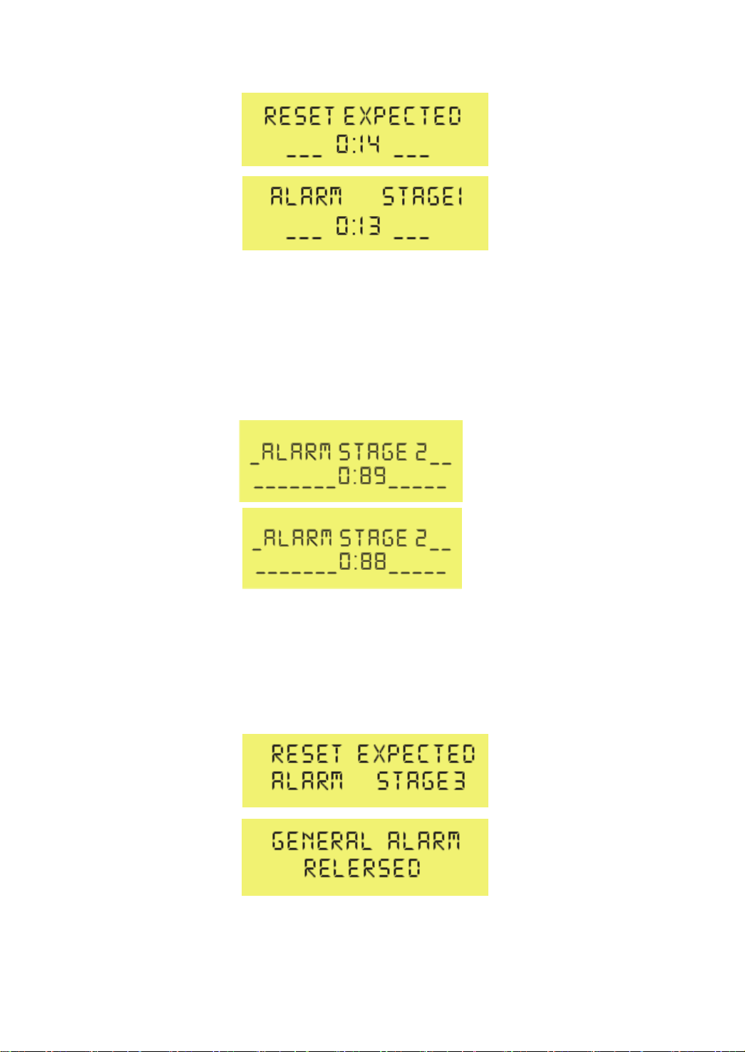
If dormant (main) period, visual indications (15 sec) are over without
OOW’s reset, system additionally activates 1st Stage Alarm located on
bridge wing area. Display is showing in 1 Hz toggle mode display as
follow.
9
Page 12
2nd St age Alarm
If dormant (main) period, visual indications (15 sec) and 1st Stage Alarm
(15 sec) are over without OOW’s reset, system additionally activates
2nd Stage Alarm. Display is showing in 1 Hz toggle mode display as follow
3rd St age Alarm
If dormant (main) period, visual indications (15 sec), 1st stage Alarm (15
sec) and 2nd stage Alarm (90 sec) are over without OOW’s reset, system
additionally activates 3rd Stage Alarm. Display is showing as follow
10
Page 13
Reset
OOW resets system by pushing reset button of BW508R or BW508RA1,
and also can push rotary encoder on BW508MAIN.
Every reset is re-starting complete count-down.
External reset devices input switching value input to reset alarm.
We offer motion detectors BW508PIR.It’s operating instruction refers to
the interleaf.
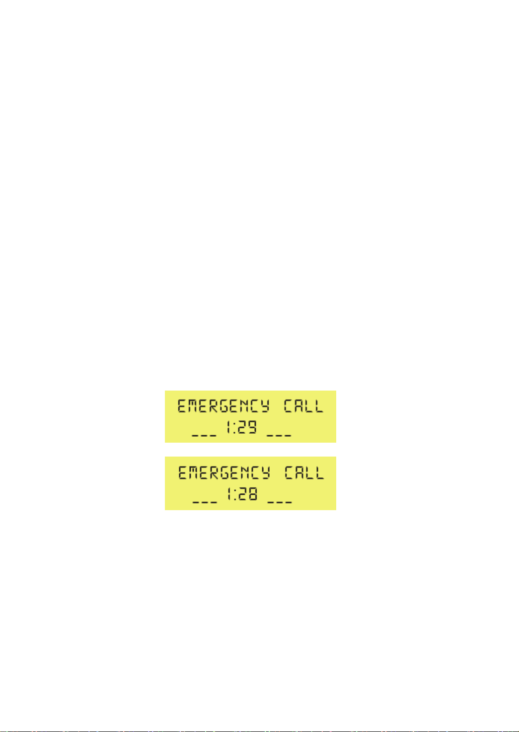
Emergency call
OOW is able to generate an emergency call by pushing Emergency call
button on BW508MAIN
This activates without delay 2nd Stage alarm and subsequently 3rd Stage
alarm later on. Display is showing as follow
Emergency Call feature is also activated when system is shut-down!
Emergency Call reset is possible by pushing Emergency call button
again.
T ransfer of alarms
Other equipment can transfer an alarm to system by switching value
11
Page 14
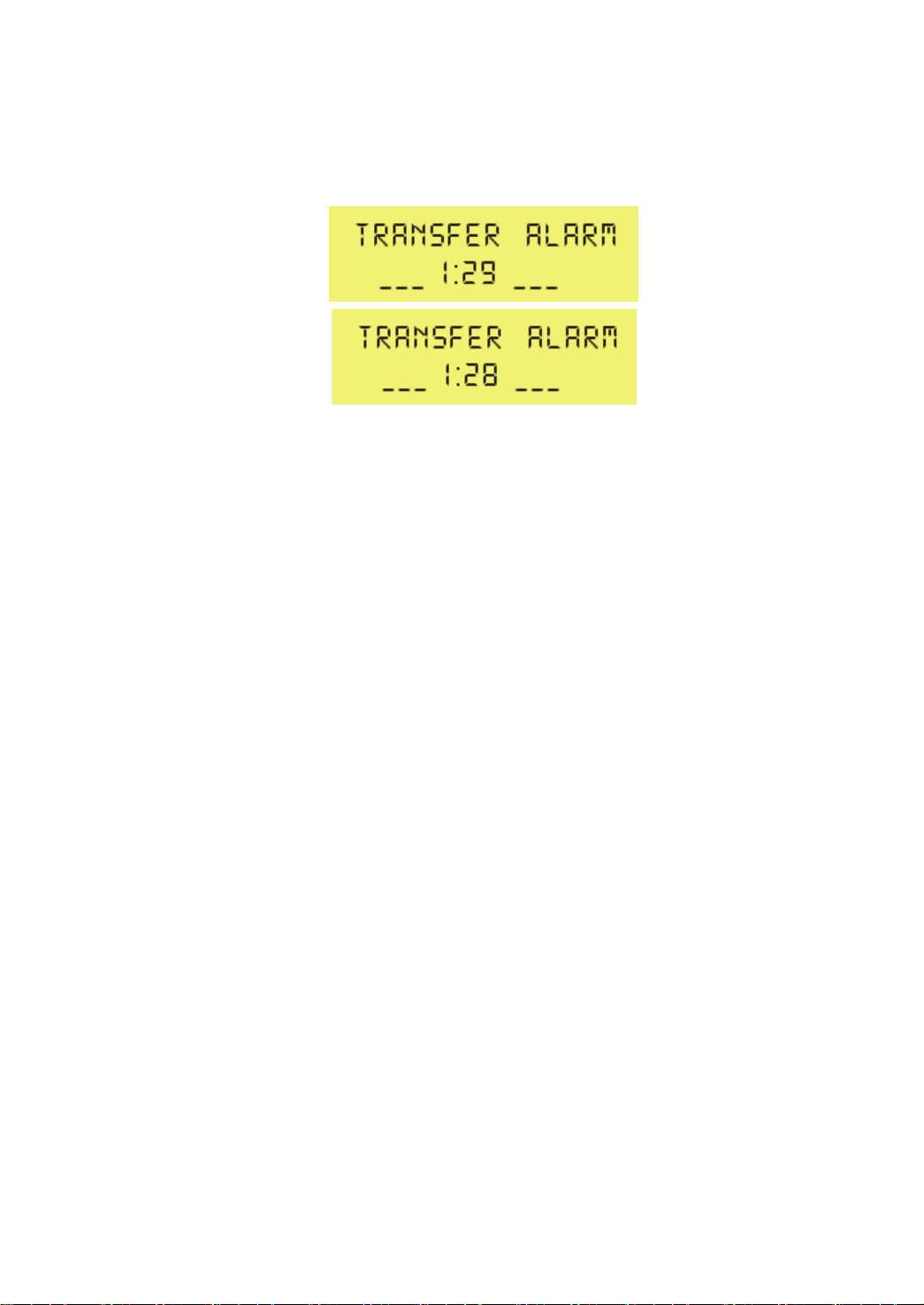
immediately actuate the “Emergency Call” system. Display is showing as
follow
System output
Status output (bit rate 4800bps)
Any change of system settings for mode or changing dormant period,
and with any activated and reset alarm can be sent to (VDR) by using the
switching value or ALR sentence.
For example:
$BNALR,,000,A,V,C1=AUT;C2=03;C3=1*hh<CR><LF>
Explanation:
C1: System is in auto mode.
C2: Td is 3min.
C3: 1st Stage Alarm is activated.
Security
The means of selecting the Operational Mode and the duration of the
Dormant Period (Td) shall be security protected so that access to these
controls should be restricted to the Master or someone with the key.
12
Page 15
Test
BW508 owns a test mode procedure to check all output relevant devices
(alarm panels, external buzzers, links to alarm devices, and system
failure contact) in a very comfortable manner.
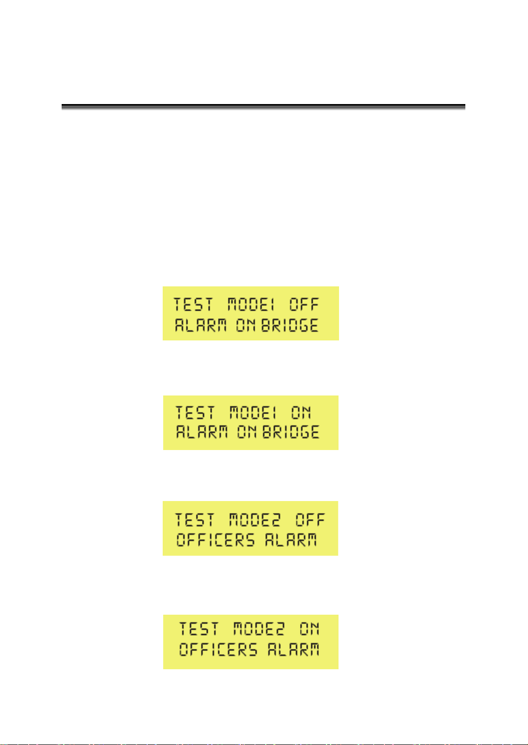
To reach this “test mode” an authorized person has to “switch off” system.
After that authorized person keep pushing rotary encoder S2 and switch
on system at the same time. System starts in “test mode 1” and display is
showing as follow
1st Stage Alarm is activated as long as S2 is pushed again. The 1st Stage
Alarm indication on BW508CONN is on. Display is showing as follow
After a.m. test in “test mode 1” is done, user has to turn S2 clockwise to
reach “test mode 2”. Display is showing as follow
nd
2
Stage Alarm is activated as long as S2 is pushed again. The 2nd
Stage Alarm indication on BW508CONN is on. Display is showing as
follow
13
Page 16
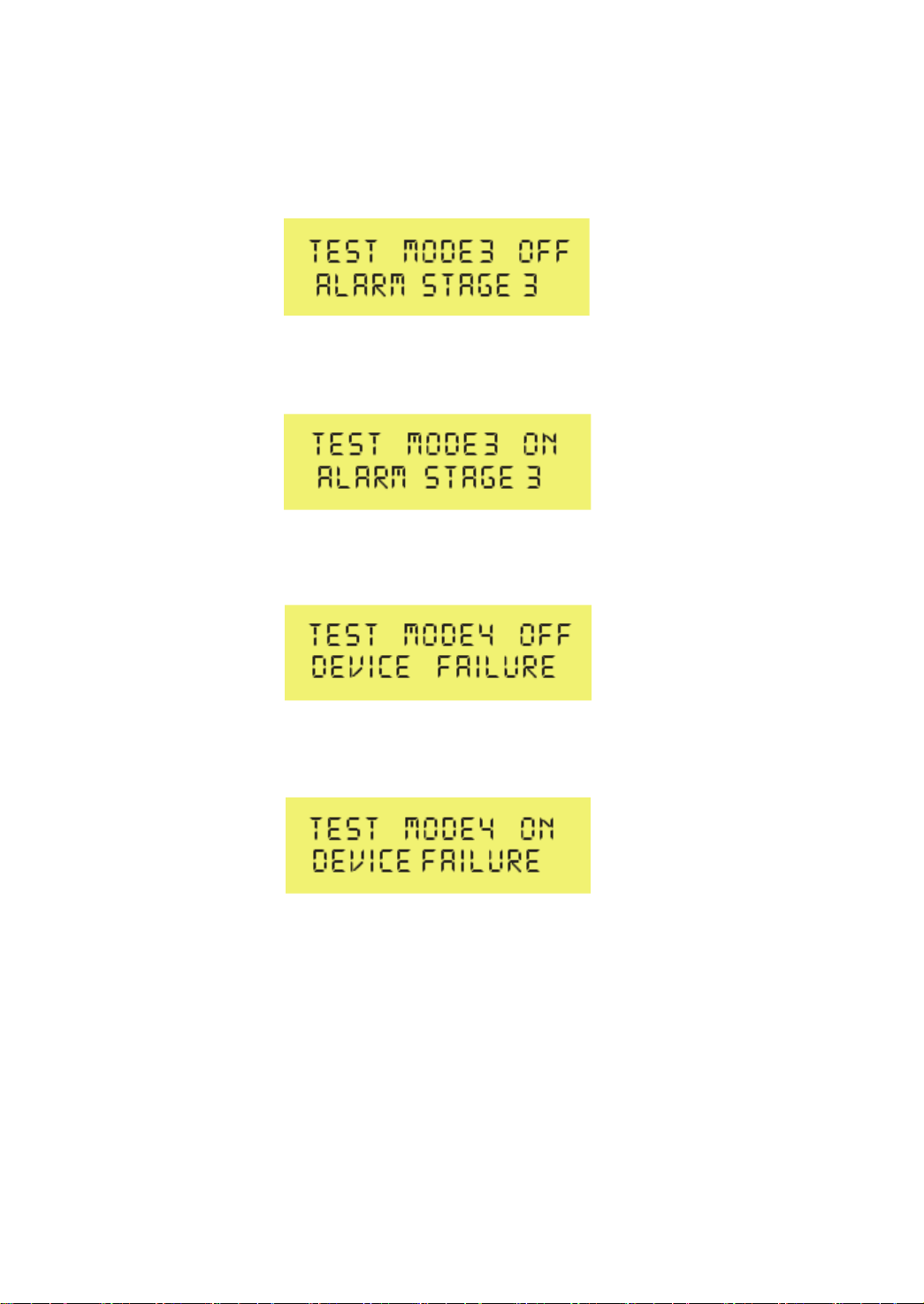
After a.m. test in “test mode 2” is done, user has to turn S2 clockwise to
reach “test mode 3”. Display is showing as follow
3rd Stage Alarm is activated as long as S2 is pushed again. The 3rd Stage
Alarm indication on BW508CONN is on. Display is showing as follow
After a.m. test in “test mode 3” is done, user has to turn S2 clockwise to
reach “test mode 4”. Display is showing as follow
Device’s failure contact opens as long as push button S2 is pushed again.
The devices failure indication on BW508CONN is off. Display is showing
as follow
For finishing “test mode” procedure “switch off” system by turning key
switch S1 on BW508MAIN left again for longer 2 sec.
14
Page 17

Malfunctions
Main power failure
Power failure indicator L1 and buzzer alarm of BW508MAIN auto turns on,
then the power will be supplied by storage battery.
Meanwhile, the POWER light of BW508MAIN goes off and BW508MAIN
outputs power failure relays to external equipments.
Press rotary encoder S2 to mute the buzzer but the power failure indicator
L1 is still on until failure solved.
Battery supply
When the supply of Main power is off, the power failure indicator and
Emergency Call facility can be operated with battery supply for a period
of 6h.
Malfunctions indication
Run normally indicator L2 on BW508MAIN is off.
Run normally indicator on BW508CONN is off.
Malfunctions output
System can output switching value for connection to central alarm panels
to repeat the malfunction indication.
15
Page 18
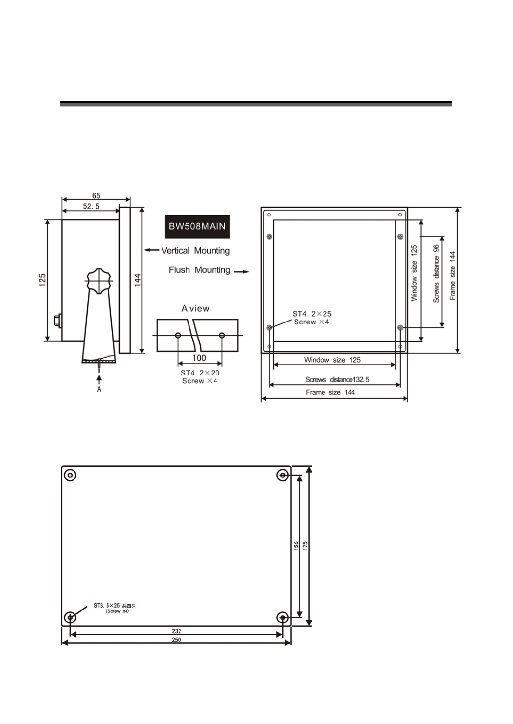
System Installation
Installation dimension
BW508MAIN unit : mm
BW508CONN
16
Page 19
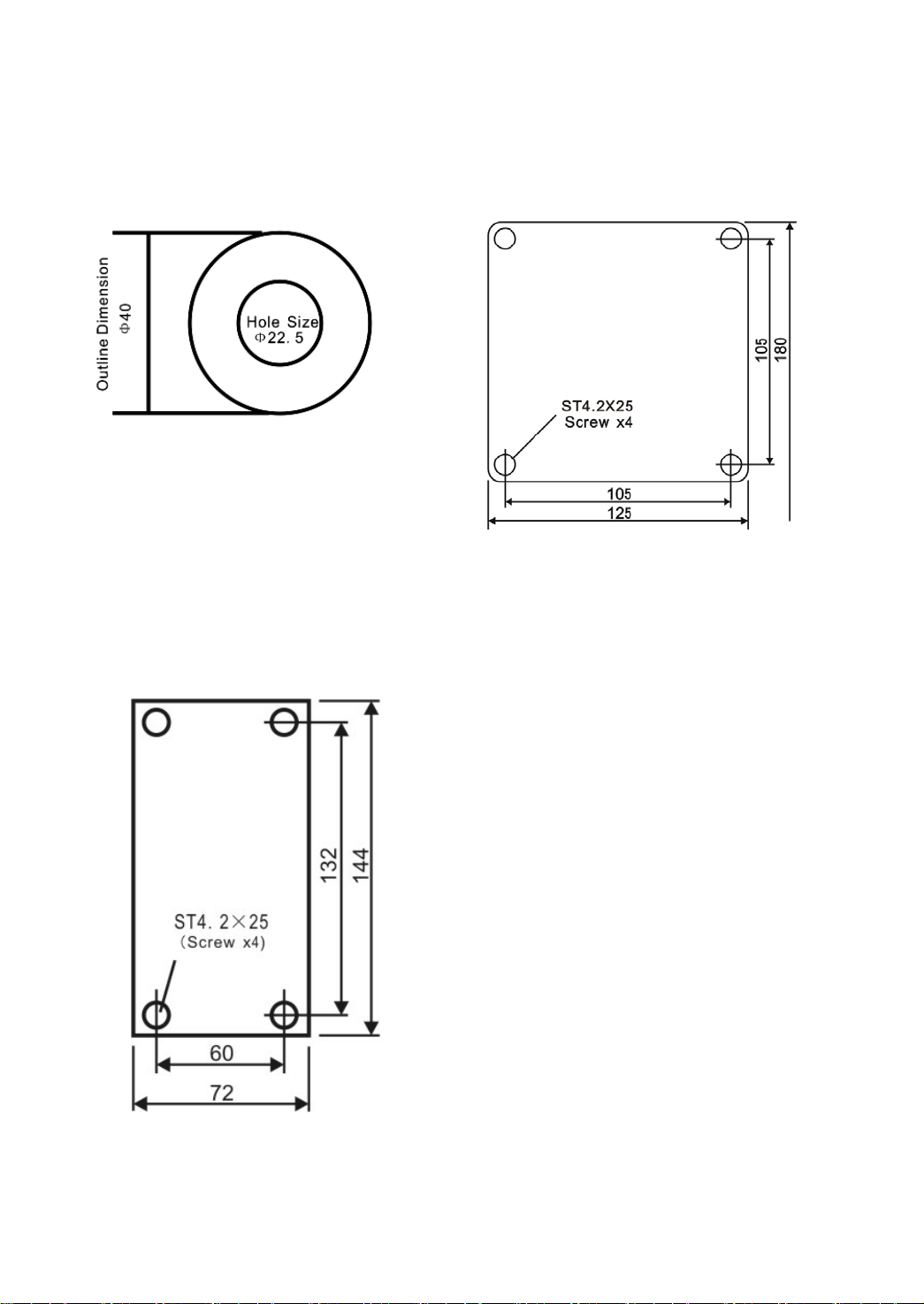
BW508R-A BW508R-B/RA1/A2-A
Flush Mounting Wall Mounting
BW508A2-B
Flush Mounting
17
Page 20
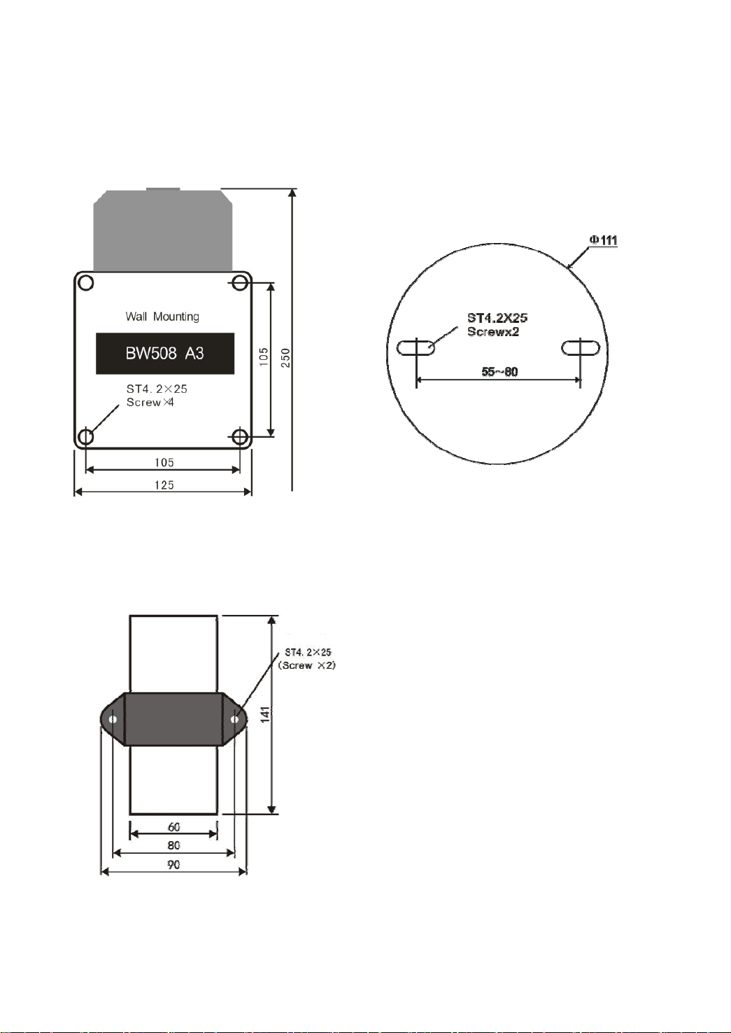
BW508A3-A BW508A3-B
Wall Mounting Wall Mounting
BW508ADPT
Wall Mounting
18
Page 21
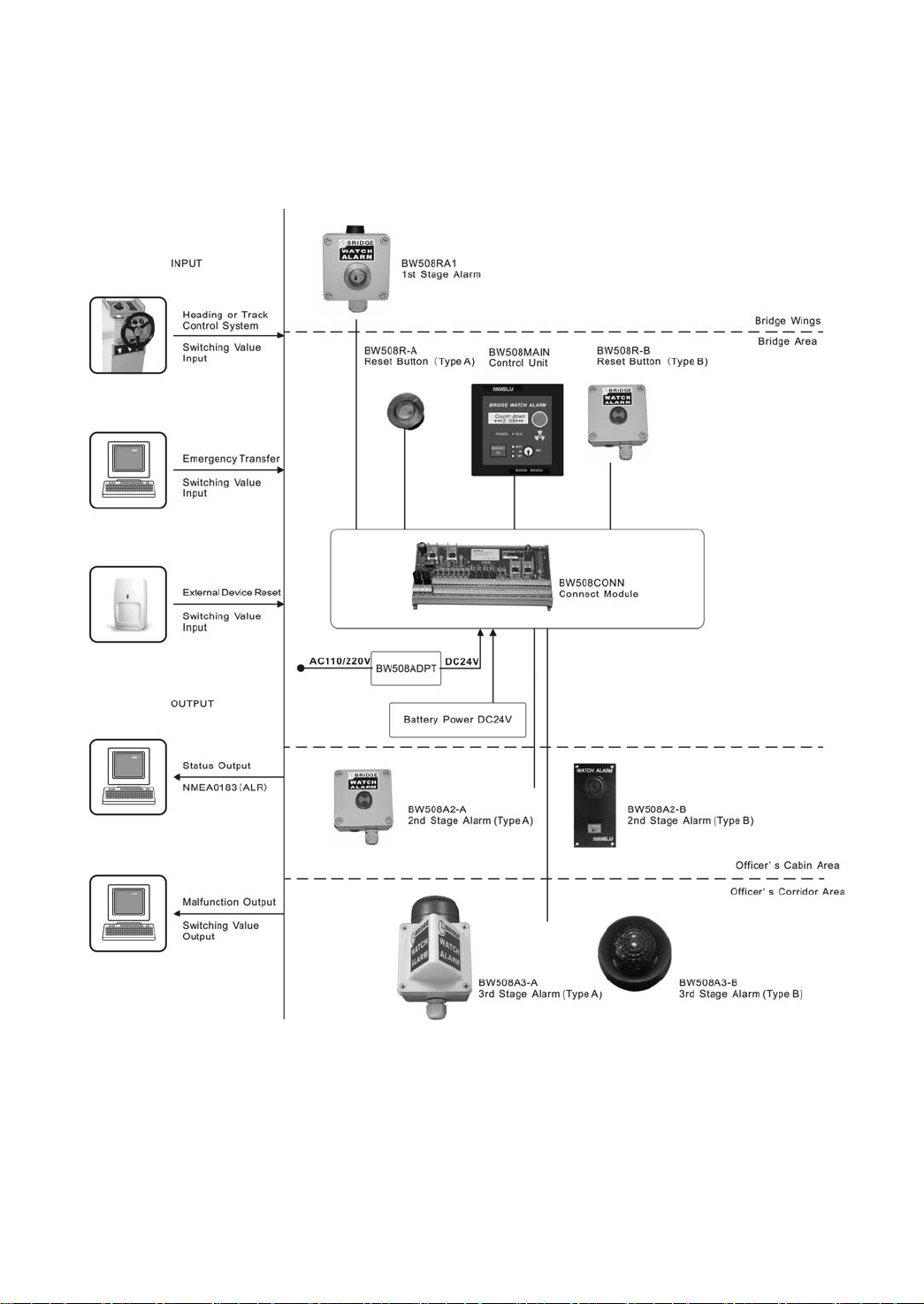
System Diagrams
19
Page 22
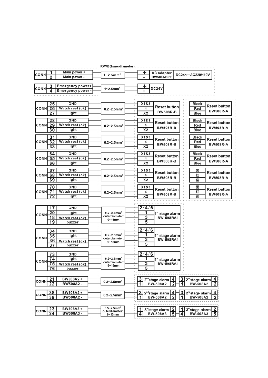
BW508 Internal Wiring Diagram
20
Page 23
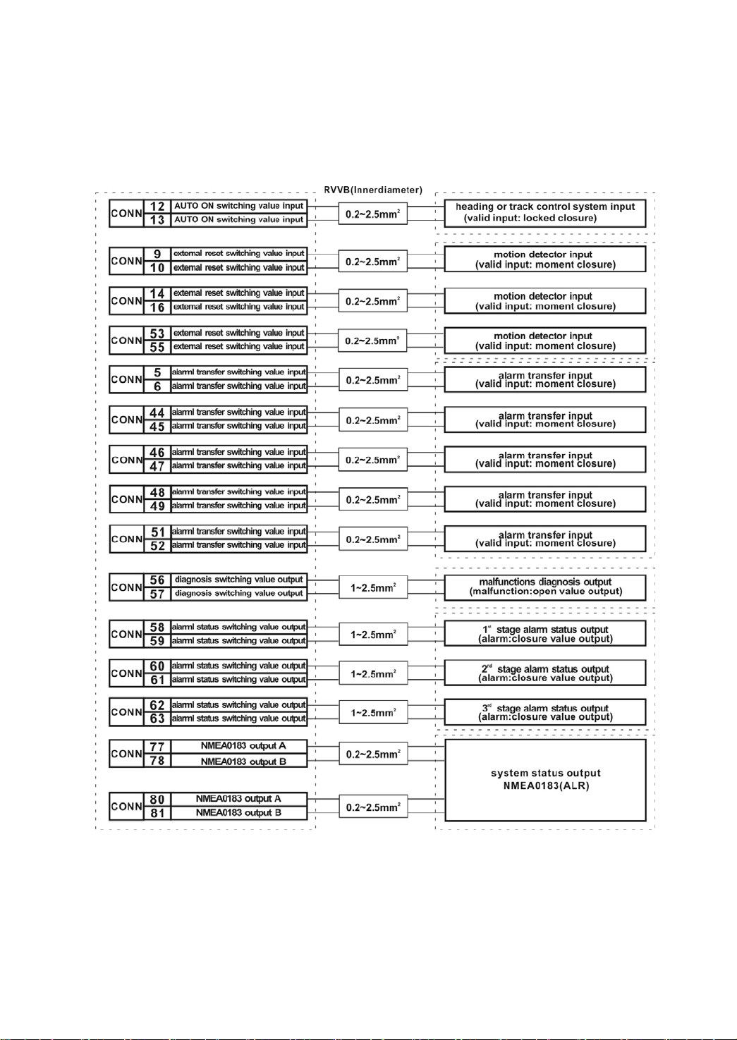
BW508 External Wiring Diagram
21
 Loading...