

Page 1
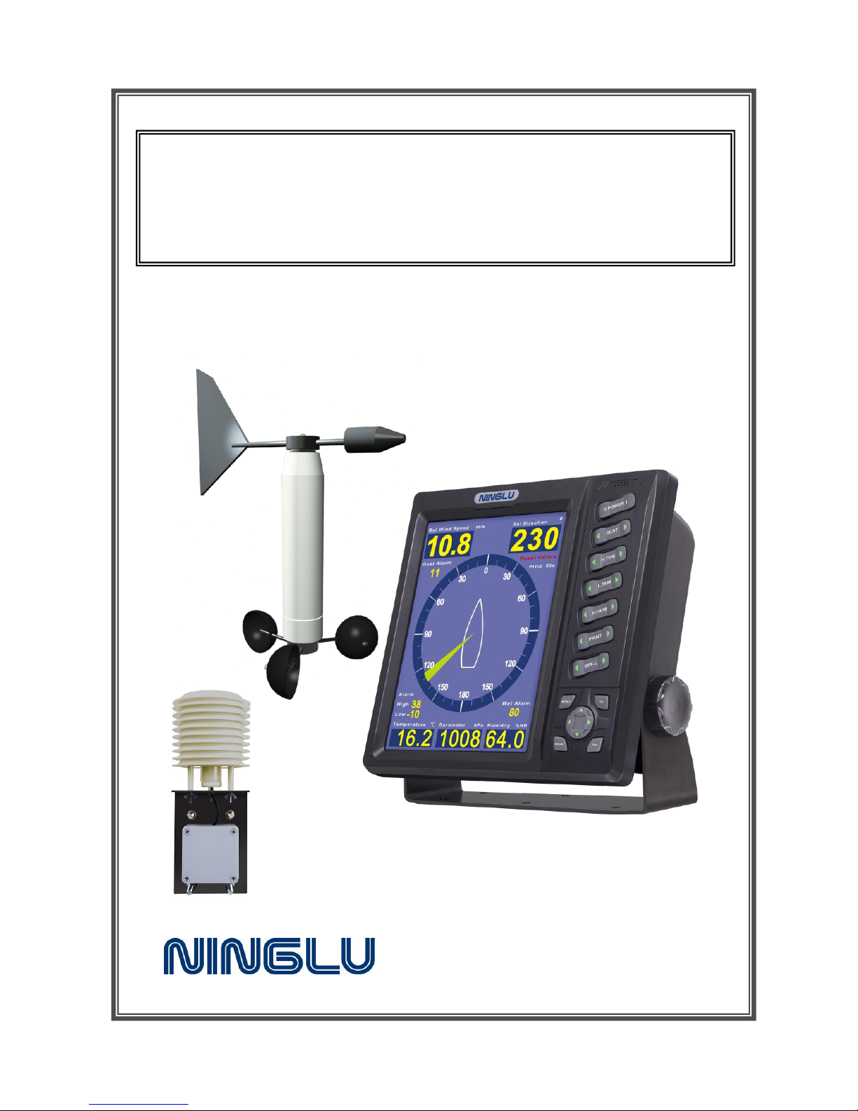
Model: AM706D
Weather Station
Operation Manual
Document: NLT-AM706D-SSEN
Edition: V140827
Page 2

Quick User Guide
Warning function: Power failure,
Wind speed (Gust), temperature
and humidity alarm.
Mute: Press any button to mute.
Selectable Relative/True speed
direction.
Selectable day and night modes.
Direction calibration: After power
on, move wind vane toward the
ship bow direction, then press the
reset button inside junction box.
Independent temperature and
humidity sensor.
Barometer sensor inside main
unit.
Page 3
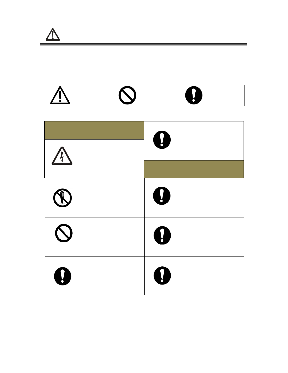
Safe Operation
Please carefully read this page before operation in
order for safe and convenient operation.
Be sure no water
or rain into unit
Operation Warn
Do not refit unit
privately
Installation Warn
Do not operate
with water
Be sure the main
unit location is
IP23
If water leakage,
Power down
immediately
Be sure the wind
sensor installed
on the ventilated
place
Power off before
installation
Do not
disassemble unit
Warn Prohibit Attention
Page 4

Contents
Introduction .................................................................... 1
Introduction ......................................................................................... 1
Measurement Principle ....................................................................... 1
System Introduction ...................................................... 3
General View .......................................................................................... 3
System Overview .................................................................................... 4
Technical Requirements ............................................... 5
Basic Parameters ................................................................................... 5
Environmental Conditions ....................................................................... 5
Technical Parameters ............................................................................. 6
Input and Output ............................................................ 7
Data transmission for NMEA0183 .................................................... 7
GPS data input—RMC ......................................................................... 7
GPS data input—GGA data input ................................................... 8
GPS data input—VTG .......................................................................... 8
Speedlog data input--VBW ................................................................ ..... 9
Gyro data input --HDT ............................................................................ 9
Main unit output--MWV ...................................................................... 9
Main unit output --MDA ................................................................... 10
Main unit output --MHU ................................................................... 10
Main unit output --MMB ................................................................... 10
Main unit output --MTA .................................................................... 10
Operating Instructions ................................................ 11
Display .................................................................................................. 11
Key Introduction .................................................................................... 12
[POWER] Power On/Off .................................................................... 13
Power Failure Alarm .......................................................................... 13
Alarm Mute ......................................................................................... 13
[GUST] Gust Alarm ........................................................................... 14
[H.TMP] High Temperature Alarm .................................................. 14
[L.TMP] Low Temperature Alarm.................................................... 15
Page 5

[H.HUM] High Humidity Alarm ....................................................... 15
[BRILL] Adjustable Brightness ....................................................... 15
[PRINT] Printer Setup ...................................................................... 16
DPU-414 Printer Setup ............................................................. 16
DPU-414 Printer Printing Contents ......................................... 17
[MODE] Mode Switch ..................................................................... 17
[D/N] Day and Night ................................ ................................ ........ 17
[MENU] ................................................................................................ 18
Maintenance ................................................................. 19
Main Unit ............................................................................................. 19
Sensor Part ......................................................................................... 19
Calibration .................................................................... 20
Installation .................................................................... 21
Main unit Installation AM706D ....................................................... 21
Table and Hanging Mounting ................................................... 21
Flushing Mounting ...................................................................... 22
Power Adapter Installation .................................................................... 23
Installation of Wind sensor AM706S ............................................. 24
Wind Vane and Wind Cup Installation .................................... 24
Integral Installation ................................................................... 25
Temperature and Humidity Sensor Installation ........................... 26
Temperature and Humidity Sensor AM706TH.............................. 26
Wiring explanation....................................................... 27
Wiring diagram of AM706D back cover ................................................. 27
System internal connection ................................................................... 28
System internal wiring diagram .............................................. 28
Wind sensor AM706S - Main unit AM706D ........................... 29
TMP and HUM sensor AM706TH-Main unit AM706D ............ 29
Main unit AM706D Power in ..................................................... 30
System external connection .................................................................. 31
System external wiring diagram ............................................. 31
Page 6
1
Introduction
Introduction
The marine weather station AM706D is a multi-functonal
measuring instrument with wind speed, direction, temperature,
humidity and barometric pressure. It can accurately measure and
display real-time relative wind speed and direction, true wind speed
and direction, air temperature, relative humidity and barometric
pressure. In addition, it can regularly print these parameters and
time, longitude and latitude, ship speed, and navigational signal. It is
important and necessary for observation and safe navigation.
AM706D is approved by China Classification Society (CCS).
The main unit AM706D adopts three mounting methods, table,
hung and flush mounting. The wind sensor AM706S should be
installed on natural ventilated place, such as mast. Please note, big
Radar antenna rotation can disturb the wind measurement. The
AM706TH is suggested to be mounted on a place there is no direct
sunlight and rain drop.
Measurement Principle
Page 7

2
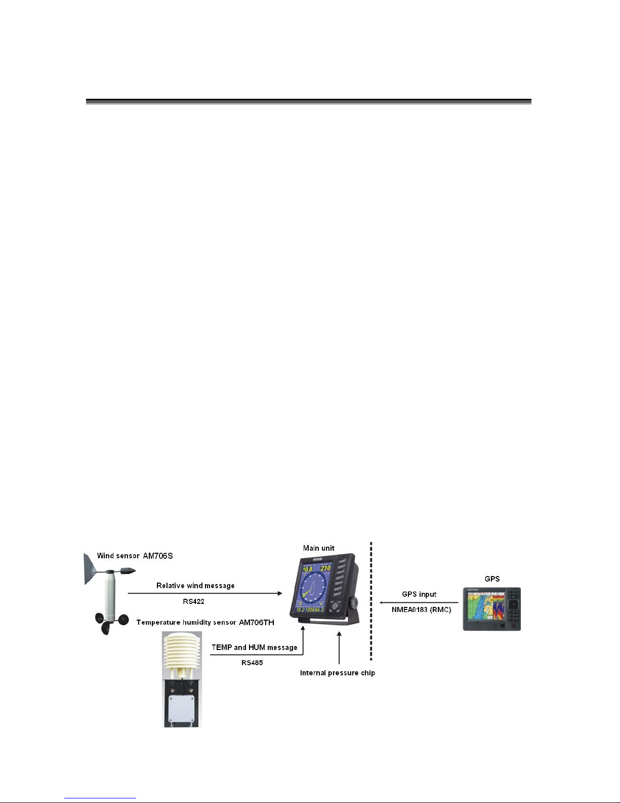
Wind sensor sends relative wind direction and speed signal (relative
to ship bow and absolute value of angle signal) in digital interface
format of RS422 to main unit through junction box.
Temperature and humidity sensor provides air temperature and
humidity signal in digital interface format of RS485 to main unit
through junction box
Barometric pressure signal is received from internal IC sensor of
main unit.
Main unit uses these signals to calculate, display and export.
True speed and direction:
There are two ways to get the true direction and speed.
First way, connecting external GPS (RMC) data input, main unit can
calculate true wind direction (relative to North Pole) and speed.
Second way, connecting both Gyro(HDT) and Speed Log(VBW) data,
main unit can display the true wind direction and speed.
Page 8
3
System Introduction
General View
Page 9

4
System Overview
Main unit AM706D
Application: Measure Barometric pressure and display values
and system control
Dimension: High 264 x width270 x thickness93 mm
Installation: Table, Hanging, Flush mounting
Location: Cab
Wind Direction and Speed Sensor AM706S
Application: Measure relative wind direction and speed,
export to Main unit
Dimension: Total high 838mm,max action radius 550mm
Installation: Binding mounting
Location: Ventilated and high outdoor, such as mast
Constitution: Wind direction and speed sensor, holder and
junction box
Wind direction sensor: Wind indicator with empennage and weight,
and absolute-value angle sensor near axis
Wind speed sensor: Three wind cups located with balanced 120o ,
photoelectric speed sensor is near axis
Holder: Used to install direction and speed sensor and to
fasten junction box
Junction box: Waterproof box and sensor converter
Temperature and Humidity Sensor AM706TH
Application: Measure temperature and humidity,
and export to Main unit
Dimension: Total high 400mm
Installation: Bulkhead mounting
Location: Ventilated outdoor,such as top of cab
Constitution: Sensor, junction box and shelter
Page 10

5
Technical Requirements
Basic Parameters
Dimension: 10 inch TFT
Display: Wind direction, speed, temperature,
humidity, barometric pressure, print
interval, alarm setting.
Wind direction simulation range: ±180°
Wind direction simulation accuracy: ±1°
Input/output port: Wind direction/speed input: 1 channel
DC power input: 2 channels
Temperature-humidity input: 1 channel
NMEA0183 input: 3 channels
NMEA0183output: 2 channels
Printer output: 1 channel
Sound-light alarm output: 1 channel
Power supply: DC24V (20~32V)
One channel power through adapter: 110/220V 50/60Hz AC
Environmental Conditions
Operating
temperature
Storage
temperature
Relative
humidity
Water
proof
Main unit
-15°C~+55°C
-20°C~+70°C
10%~90%
IP23
Wind sensor
-15°C~+85°C
-20°C~+85°C
10%~100%
IP56
Temperature
humidity sensor
-20°C ~+80°C
-20°C ~+80°C
0%~100%
IP54
Page 11

6
Technical Parameters
Wind direction range: 0~360°
Wind direction accuracy: ±1°
Wind speed range: 1.2~25m/s
Wind speed accuracy: ±5%(min 0.1m/s)
Min start speed: ≤1.2m/s
Temperature range: -20~+80°C
Temperature accuracy: ±0.5°C
Humidity range: 0~100%RH
Humidity accuracy: ±4.5%RH
Barometric pressure range: 500~1100hPa
Barometric pressure accuracy: ±4hPa
Page 12
7
Input and Output
Data transmission for NMEA0183
Data transmission adpots NMEA0183 format and conforms
IEC61162-1 standards.
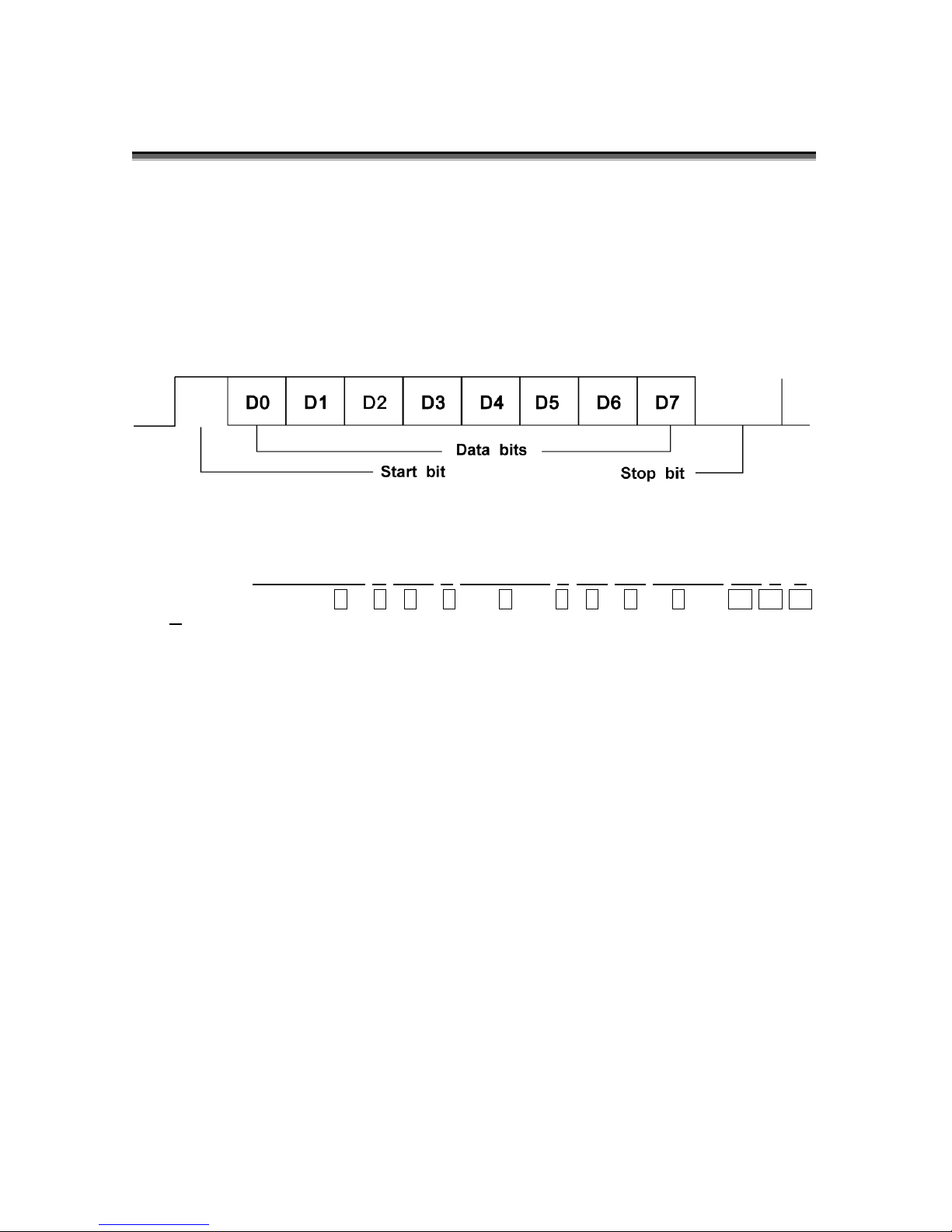
Date is transmitted in serial asynchronous form. 4800 baud rate is
4800, 8-bit data, no parity bit and one stop bit.
GPS data input—RMC
$--RMC,hhmmss.ss,A,llll.ll,a,yyyyy.yy,a,x.x,x.x,xxxxxx,x.x,a*h
h<CR><LF>
(1) UTC of position fix
(2) Status, A=data valid, V=navigation receiver warning
(3) Latitude
(4) Latitude, N/S
(5) Longitude
(6) Longitude, E/W
(7) Speed over ground, knots
(8) Course over ground, degree true
(9) UTC date, dd/mm/yy
(10) Magnetic variation, degree, E/W
(11) Mode indicator, A=Autonomous mode
D=Differential mode
E=Estimated(dead reckoning)mode
M=Manual input mode
S=Simulator mode
N=Data not valid
(12) Checksum value
1 2 3 4 5 6 7 8 9 10 11 12
Page 13

8
GPS data input—GGA data input
$--GGA,hmmss.sss,ddmm.mmmm,a,dddmm.mmmm,a,x,xx,
x.x,x.x,M,x.x,M,x.x,xxxx*hh<CR><LF>
(1) UTC of position
(2) Latitude
(3) Latitude N/S
(4) Longitude
(5) Longitude E/W
(6) GPS quality indicator:0=fix not available or invalid
1= GPS SPS mode, fix valid
2=differential GPS, SPS mode, fix valid
6=Estimated (dead reckoning) mode
(7) Number of satellites in use, 00-12, may be different from the number
in view
(8) Horizontal dilution of precision
(9) Antenna altitude above/below mean sea level(geoid)
(10) Units of antenna altitude, m
(11) Geoidal separation
(12) Units of geoidal separation, m
(13) Age of differential GPS data
(14) Differential reference station ID, 0000-1023
(15) Checksum value
GPS data input—VTG
$--VTG,x.x,T,x.x,M,x.x,N,x.x,K,a*hh<CR><LF>
(1) Course over ground, degree true
(2) Course over ground, degree magnetic
(3) Speed over ground, knots
(4) Speed over ground, km/h
(5) Mode indicator, A=Autonomous mode
D=Differential mode
E=Estimated(dead reckoning)mode
M=Manual input mode
S=Simulator mode
N=Data not valid
(6) Checksum value
1 2 3 4 5 6 7 8 10
9
11
12
13
1 2 3 4 5 6
14
15
Page 14

9
Speedlog data input--VBW
Water-referenced and ground-referenced speed data
$--VBW,x.x,x.x,A,x.x,x.x,A,x.x,A,x.x,A*hh<CR><LF>
(1) Longitudinal water speed, Knots
(2) Transverse water speed, Knots
(3) Status:water speed, A=data valid, V=data invalid
(4) Longitudinal ground speed, Knots
(5) Transverse ground speed, Knots
(6) Status:ground speed, A=data valid, V=data invalid
(7) Stern transverse water speed, Knots
(8) Status:stern water speed, A=data valid, V=data invalid
(9) Stern transverse ground speed, Knots
(10) Status:stern ground speed, A=data valid, V=data invalid
(11) Checksum value
Gyro data input --HDT
$--HDT,x.x,T*hh<CR><LF>
(1) Heading, degree true
(2) T = true
(3) Checksum value
Main unit output--MWV
$--MWV,x.x,a,x.x,a,A*hh<CR><LF>
(1) Wind angle, 0° to359°
(2) Reference, R = relative, T = true
(3) Wind speed
(4) Wind speed units, K=km/h
M=m/s
N=knots
(5) Status, A = data valid V=data invalid
(6) Checksum value
1 2 3 4 5 6
1 2 3 4 5 6 7 8 10 9 11
1 2 3
Page 15

10
Main unit output --MDA
$--MDA,x.x,I,x.x,B,x.x,C,x.x,C,x.x,x.x,x.x,C,x.x,T,x.x,M,x.x,N,x.x,M*hh<CR><LF>
1 2 3 4 5 6 7 8 9
10 11
12 13 14 15 16 17 18 19 20 21
(1) Barometric pressure (2) Barometric pressure unit, I=inHg
(3) Barometric pressure (4) Barometric pressure unit, B=bars
(5) Air temperature (6) Temperature unit, C=degree
(7) Water temperature (8) Temperature unit, C=degree
(9) Relative humidity, % (10) Absolute humidity, %
(11) Dew point (12) Dew point temperature, C=degree
(13) Relative direction (14) Wind direction unit, degree T=true
(15) Relative direction (16) Relative direction, degree M=Relative
(17) Wind speed (18) Wind speed unit, N=knots
(19) Wind speed (20) Wind speed unit, M=m/s
(21) Checksum value
Main unit output --MHU
$--MHU,x.x,x.x,x.x,C*hh<CR><LF>
1 2 3 4 5
(1) Relative humidity, %
(2) Absolute humidity, %
(3) Dew point
(4) Dew point unit, C=degree
(5) Checksum value
Main unit output --MMB
$--MMB,x.x,I,x.x,B*hh<CR><LF>
1 2 3 4 5
(1) Barometric pressure
(2) Barometric pressure unit, I=inches of mercury
(3) Barometric pressure
(4) Barometric pressure unit, B=bars
(5) Checksum value
Main unit output --MTA
$--MTA,x.x,C*hh<CR><LF>
1 2 3
(1) Air temperature
(2) Temperature unit, C=degree
(3) Checksum value
Page 16
11
Operating Instructions
Display
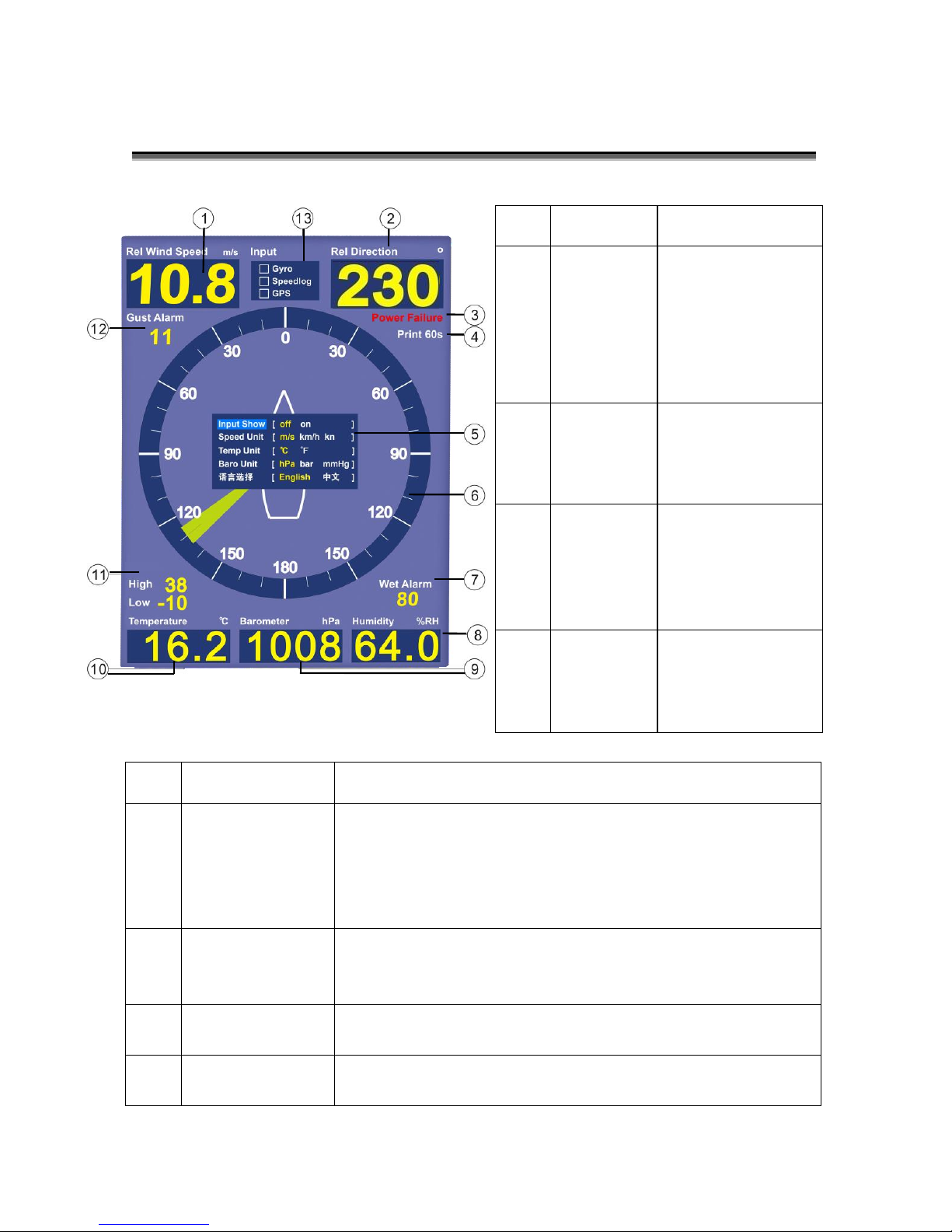
No.
Display
Explanation
5
Menu
Press [MENU] to open window
Use direction keys to set up parameters
Press [OK] to save settings and exit
Automatically save settings and exit without operation
in 10s
6
Relative wind
direction
analog display
Analog display the relative direction of wind and ship
bow
7
H.HUM alarm
Set Value
Press [H.HUM] to set alarm value or turn off
8
Current
relative HUM
Display current relative humidity
No.
Display
Explanation
1
Current
relative/tr
ue wind
speed
Press [MODE] to
switch relative/
true mode.
Press [MODE] to
switch speed
unit.
2
Current
relative/tr
ue wind
direction
Press [MODE] to
switch relative
or true mode.
3
Power
failure
alarm
Anyone of two
channels power
supply failure
causes Power
Failure Alarm
4
Print set
value
Press [PRINT] to
select the
interval time of
printing.
Page 17
12
9
Current
Barometric
pressure
Press [MENU] to switch Barometric pressure unit
10
Current TEMP
Press [MENU] to switch temperature unit
11
H/L TEMP
Alarm Value
Press [H.TMP] or [L.TMP] to set alarm value or turn off
12
Gust Alarm
Press [GUST] to set alarm value or turn off
13
Input Signal
Window
Press [MENU] to open the window and observe input
signal
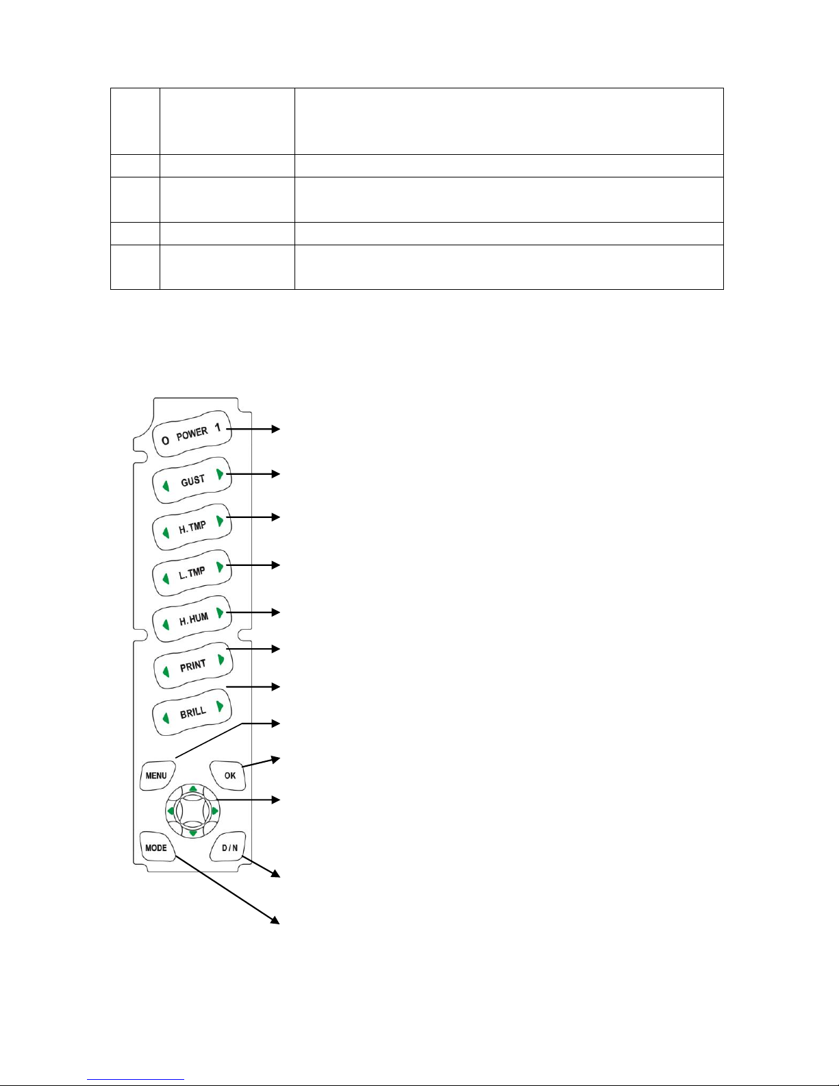
Key Introduction
Switch on/off:0-OFF,1-ON
Gust Alarm:OFF、1~25m/s
High Temperature Alarm:-20~80℃、OFF
Low Temperature Alarm:OFF、-20~80℃
High Humidity Alarm:OFF、1~99%RH
Print Setup:off、5s、15s、30s、60s
Brightness:Adjustable 8 levels,dim ~ bright
[OK]:In menu, press [OK] to save settings
Direction Key:In menu, up/down keys for options and
left/right keys for parameters
parameters
[MODE]:Switch relative and true mode
[D/N]:Switch day and night display
[MENU]:Open menu and automatically save/exit
Page 18

13
[POWER] Power On/Off
Press[POWER 1]to turn on the system,software version is
shown at the top left top corner and then the main display.
Power Failure Alarm
After turning on, it self-checks the both channels of power supply.
Anyone channel is disconnected, it will cause Power Failure alarm.
When power failure alarm is triggered, the main unit buzzer provides
long tone alarm (external alarm will not be on when power failure)
and red words ‘Power Failure’ are flashing.
Alarm Mute
When alarm is triggered, press any button to mute the alarm
(Buzzer and external alarm), but flashing words are still on (External
light alarm is also on). When the alarm is triggered again, the system
will give the alarm again.
Flashing words (External light alarm) disappear when alarm is
turnoff or removed.
Page 19
14
[GUST] Gust Alarm
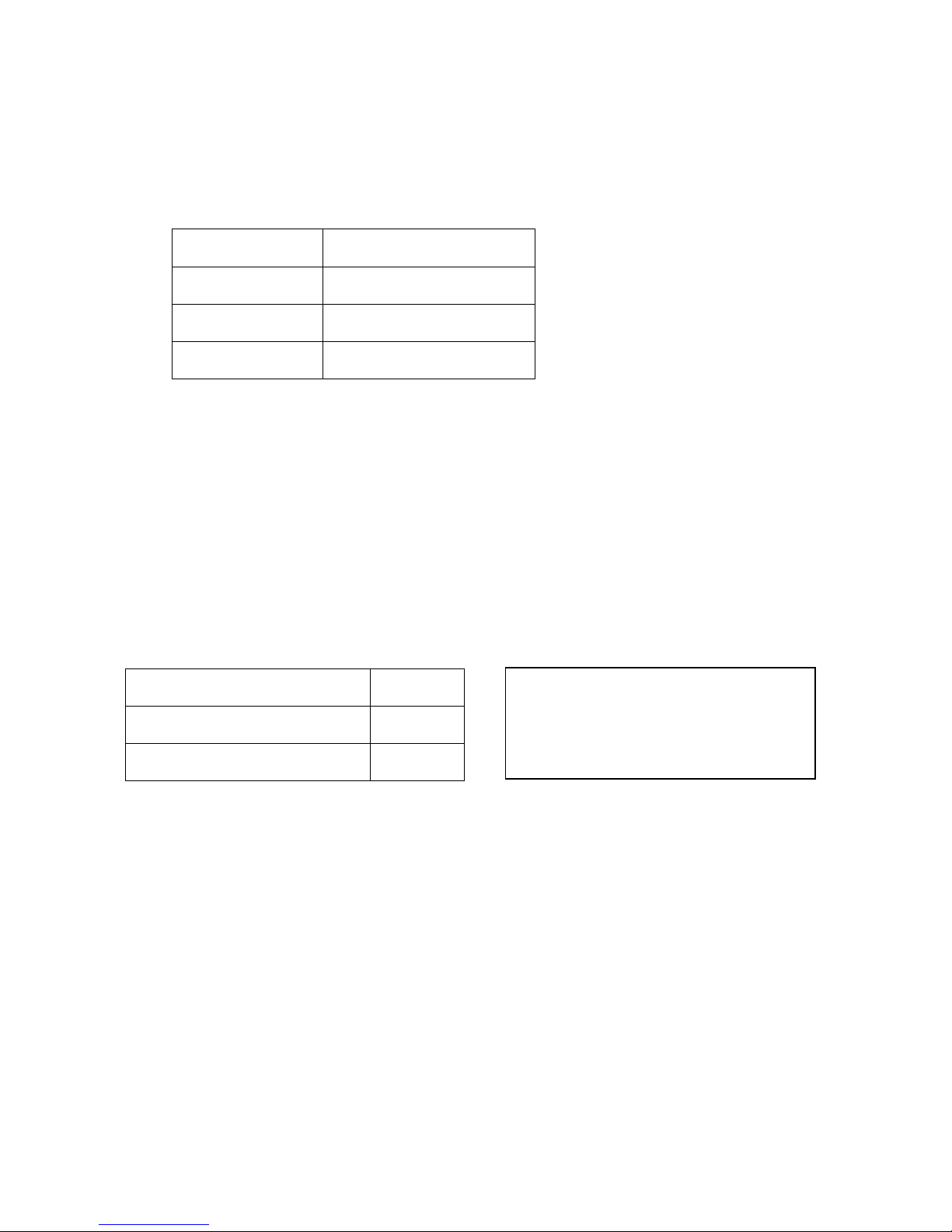
Press [GUST] left and right arrowheads to set gust alarm limits and
the factory setting is OFF.
Set Value
Unit
OFF、1~25
m/s
OFF、1~90
km/h
OFF、1~49
kn
When current relative/true wind speed is over alarm limits, main unit
buzzer and external alerter are turned on, wind value color turns
yellow to red and continuously flashing.
[H.TMP] High Temperature Alarm
Press left/right arrows of [H.TMP] to set the high temperature alarm
and factory setting is OFF.
Set Value
Unit
L.TMP ~80、OFF
℃
L.TMP ~176、OFF
℉
When current temperature is higher than alarm limits, main unit
buzzer and external alerter are turned on, temperature value color
turns yellow to red and continuously flashing.
H.TMP limit should be higher
than L.TMP limit
Page 20
15
[L.TMP] Low Temperature Alarm
Press left/right arrows of [L.TMP] to set the low temperature alarm
and factory setting is OFF.
Set Value
Unit
OFF、-20 ~ H.TMP
℃
OFF、 -4 ~ H.TMP
℉
When current temperature is lower than alarm limits, main unit
buzzer and external alerter are turned on), temperature value color
turns yellow to red and continuously flashing.
[H.HUM] High Humidity Alarm
Press left/right arrows of [H.HUM] to set the high humidity alarm and
factory setting is OFF.
Settings:OFF、1~99%RH
When current relative humidity is less than alarm limits, main unit
buzzer bells, humidity number color becomes from yellow to red and
continuously flashing.
[BRILL] Adjustable Brightness
Press left and right arrows of [BRILL] to adjust the screen brightness
(8 levels) for different ambient brightness.
H.TMP limit should be higher
than L.TMP limit
Page 21

16
[PRINT] Printer Setup
Press left and right arrows of [PRINT] to set print functions. Factory
setting value is OFF (print off).
Set value:OFF、5s、15s、30s、60s,which is the interval time of
auto print. For example, when print setup is 30s, the connected
DPU-414 printer will automatically print corresponding data every 30
seconds.
DPU-414 Printer Setup
Dip SW-1
1 (OFF):Input=Serial
2 (ON ):Printing Speed=High
3 (ON ):Auto Loading=ON
4 (OFF):Auto LF=OFF
5 (ON ):Setting Command=Enable
6 (OFF):Printing
7 (ON ):Density
8 (ON ):=100%
Dip SW-2
1 (OFF):Printing Columns=80
2 (ON ):User Font Back-up=ON
3 (ON ):Character Select=Normal
4 (ON ):Zero=Normal
5 (ON ):International
6 (ON ):Character
7 (ON ):Set
8 (OFF):=U.S.A.
Dip SW-3
1 (ON ):Data Length=8 bits
2 (ON ):Parity Setting=No
3 (ON ):Parity Condition=Odd
4 (ON ):Busy Control=H/W Busy
5 (ON):Baud
6 (OFF ):Rate
7 (OFF):Select
8 (OFF):=4800 bps.
Page 22

17
Relative wind direction and speed
Absolute wind direction and speed
Temperature
Relative humidity
Air pressure
Time
N Northern
latitude
S Southern
latitude
E East
longitude
W West
longitude
Heading
Speed
DPU-414 Printer Printing Contents
1. Relative Wind:250° 5.4m/s True Wind:321° 3.2m/s
2. Temperature:16.2℃ Humidity:64.0%RH Barometer:1008hPa
3. 03:08 32°01.2524N 118°42.0208E Heading:190.4° Speed:0.0Knots
*Note:Do not print the messages on the third line when no GPS or
course and speed information input
[MODE] Mode Switch
Press [MODE] to switch the two wind display modes:
relative wind speed/direction and true wind speed/direction.
[D/N] Day and Night
Press [D/N] to switch the two screen palettes:
black background for night and blue background for daytime.
Page 23
18
[MENU]
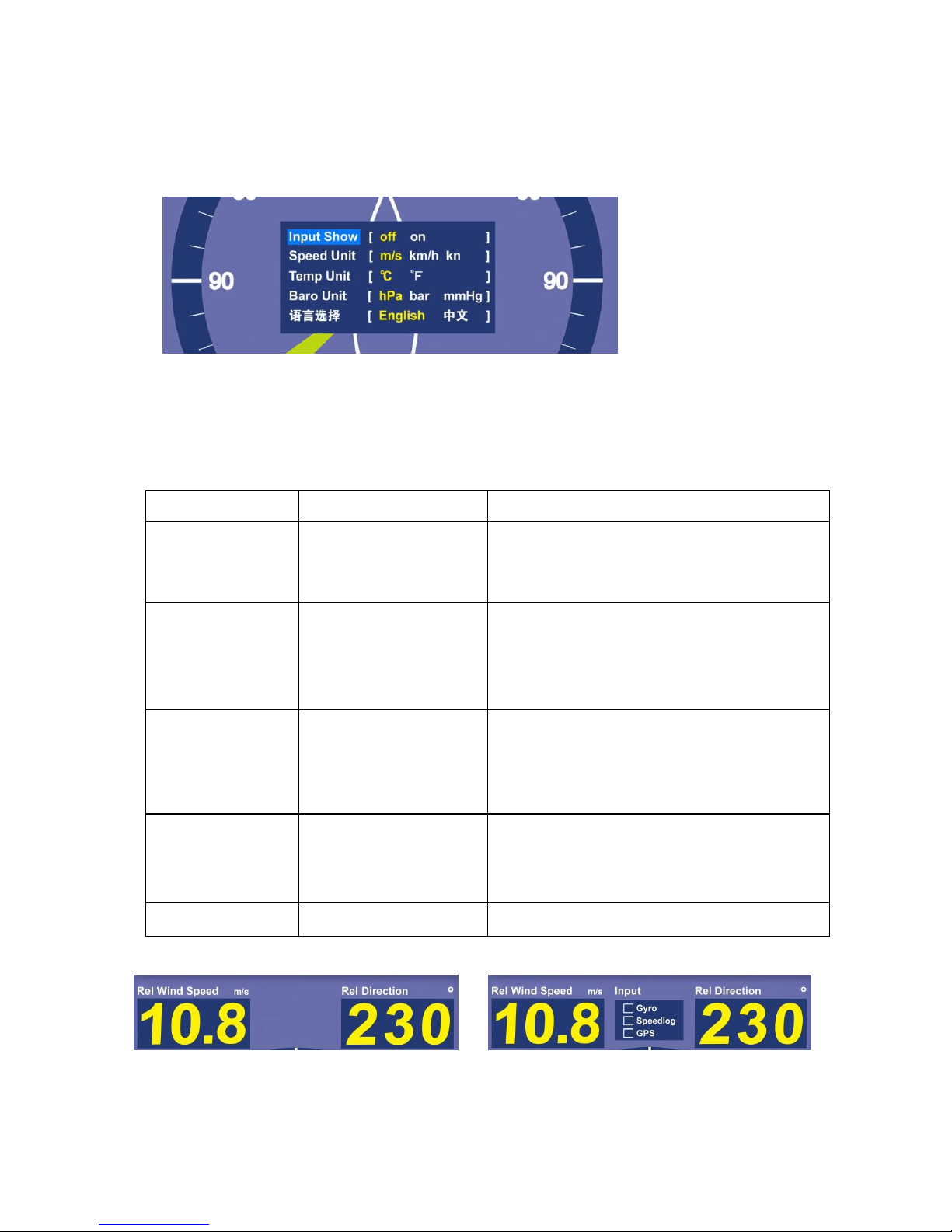
Press [MENU] to open menu window
Press up/down arrow buttons for main options and left/right
buttons for settings. Press [OK] to save the set values and exit or
automatically save and exit without operation in 10s.
Menu item
Set Value
Explanation
Input Display
OFF ON
Turn on/off input signal window,
observe gyro, speedlog, GPS
signal input situation *
Speed Unit
m/s km/h kn
Gust alarm and current
measured values automatically
convert with speed unit
conversion
Temperature
Unit
°C °F
H/L TEMP alarm and current
measured values automatically
convert with temperature unit
conversion
Barometric
pressure Unit
hPa bar
mmHg
Current measured values
automatically convert with
barometric unit conversion
Language
English 中文
Select display language
* Note: Input display OFF * Note: Input display ON
Page 24

19
Maintenance
Main Unit
The main unit is maintenance-free.
If doing the cleaning, use soft cloth and mild detergent, and avoid
water drop.
Sensor Part
When there is ice or dirt on sensor to disturb the normal work, please
clear in time.
Regularly check external mounting bolts to avoid looseness and the
abrasion and ageing of cables
When the equipment breaks down, please contact our engineers of
after-sale service department in time. Please do not do the service
by yourself.
Page 25
20
Calibration
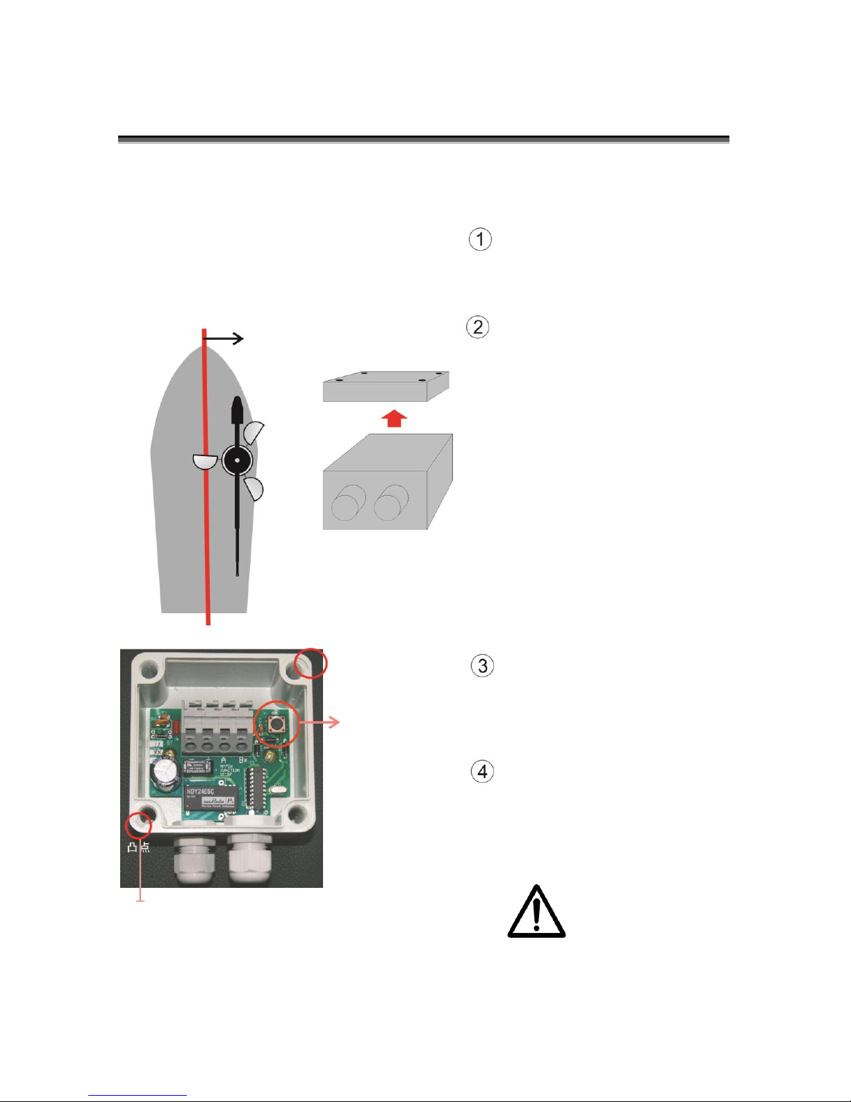
Calibration of AM706 wind vane after finishing the installation.
Press [POWER] to turn on
Move wind vane arrow parallel
to the keel line, toward to the
bow side. Then open the
junction box.
Press the calibration button in
the waterproof junction box
and display relative wind
direction ‘zero’ on main unit
Close the waterproof
junction box. The groove on
box body and the salient
point on box cover should be
corresponding to each other.
Wrong assembly of
cover causes water leakage.
Salient point
Groove
Calibration
Keel line
Page 26
21
Installation
Main unit Installation AM706D
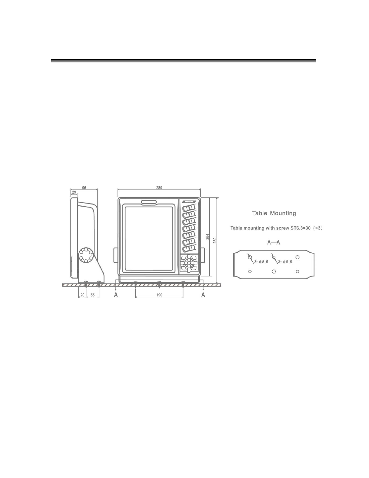
The Main unit has three mounting methods, table, hanging and flush
mounting.
Table and Hanging Mounting
The holder supplied by original factory setting is used in table and
hung mounting.
Unit:mm
Page 27
22
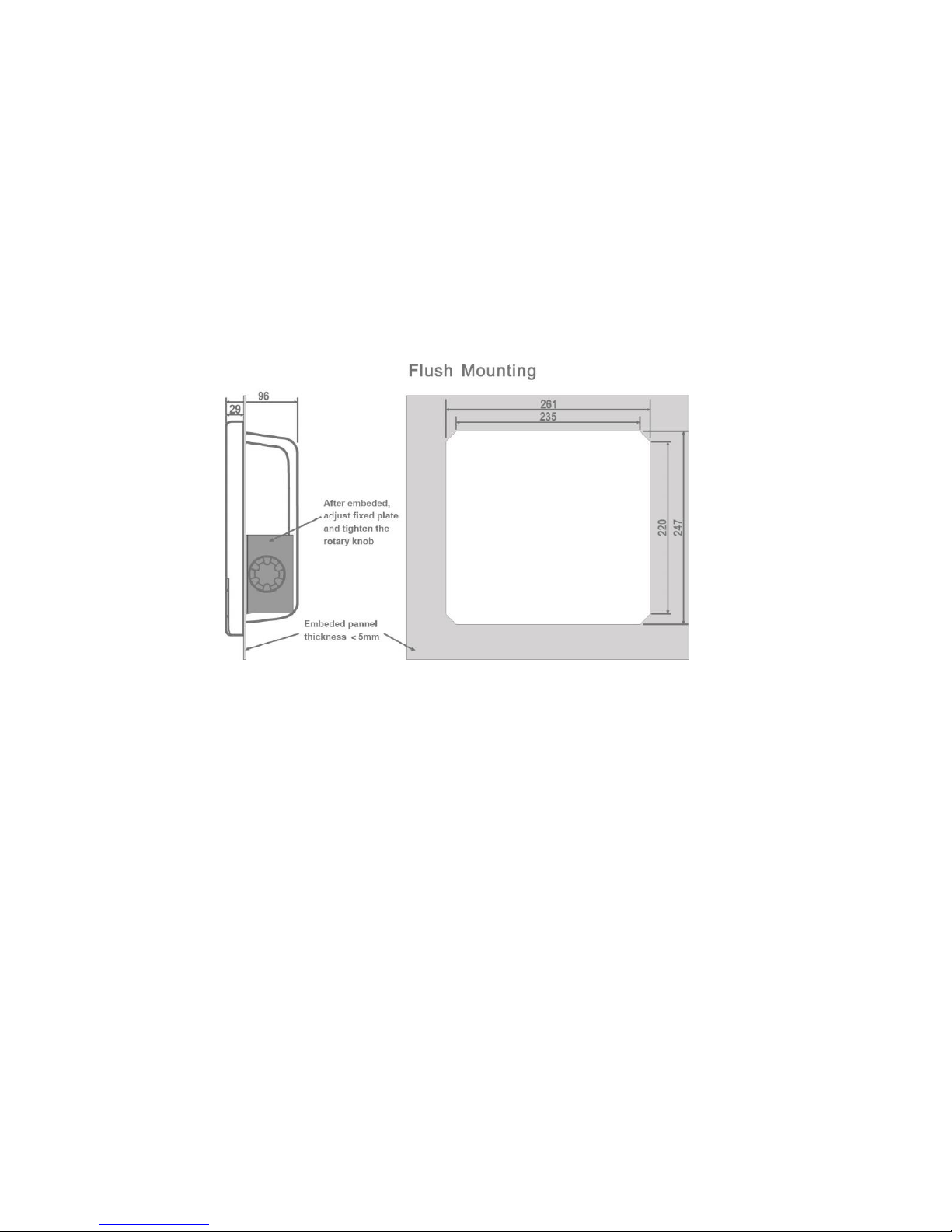
Flushing Mounting
The holder supplied by original factory setting should be used in flushing
mounting.
Embed the main unit into the bridge control panel (the dimension is shown
below) and tighten the rotary knob to fix the main unit.
Unit:mm
Page 28
23
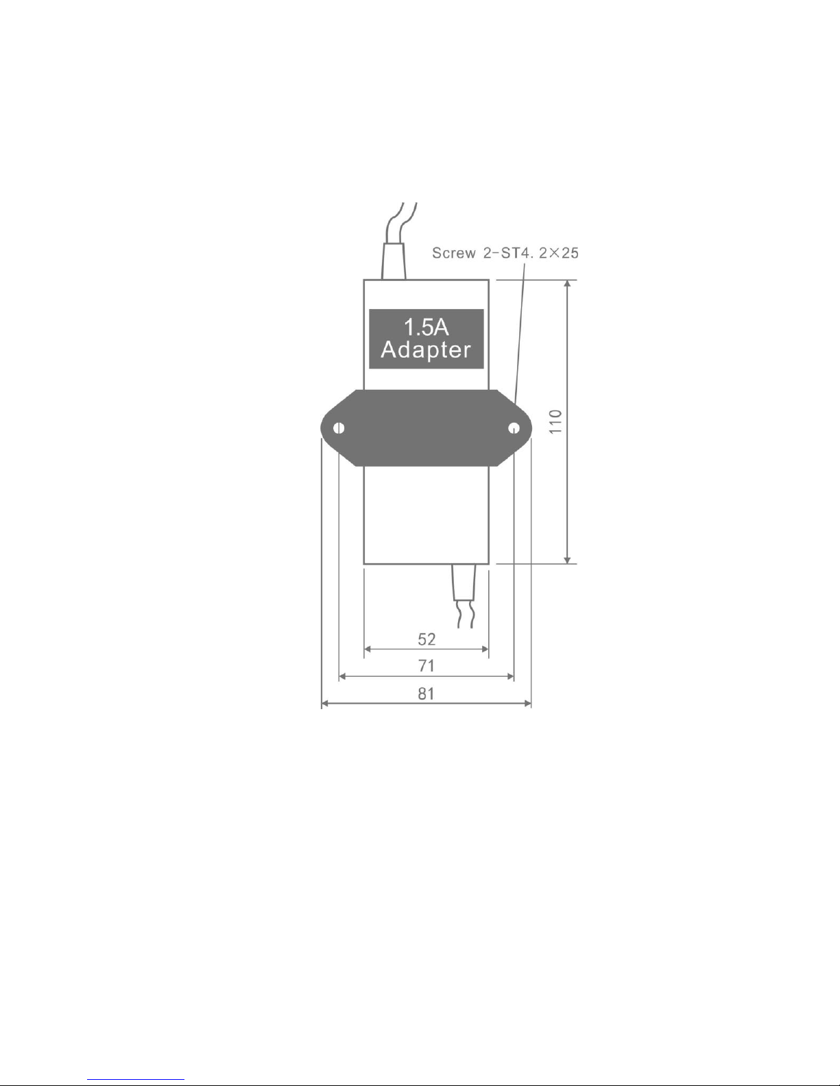
Power Adapter Installation
Power adapter(GA-240150),AC220/110V to DC24V,adapter holder
and screws.
Unit:mm
Page 29
24
Installation of Wind sensor AM706S
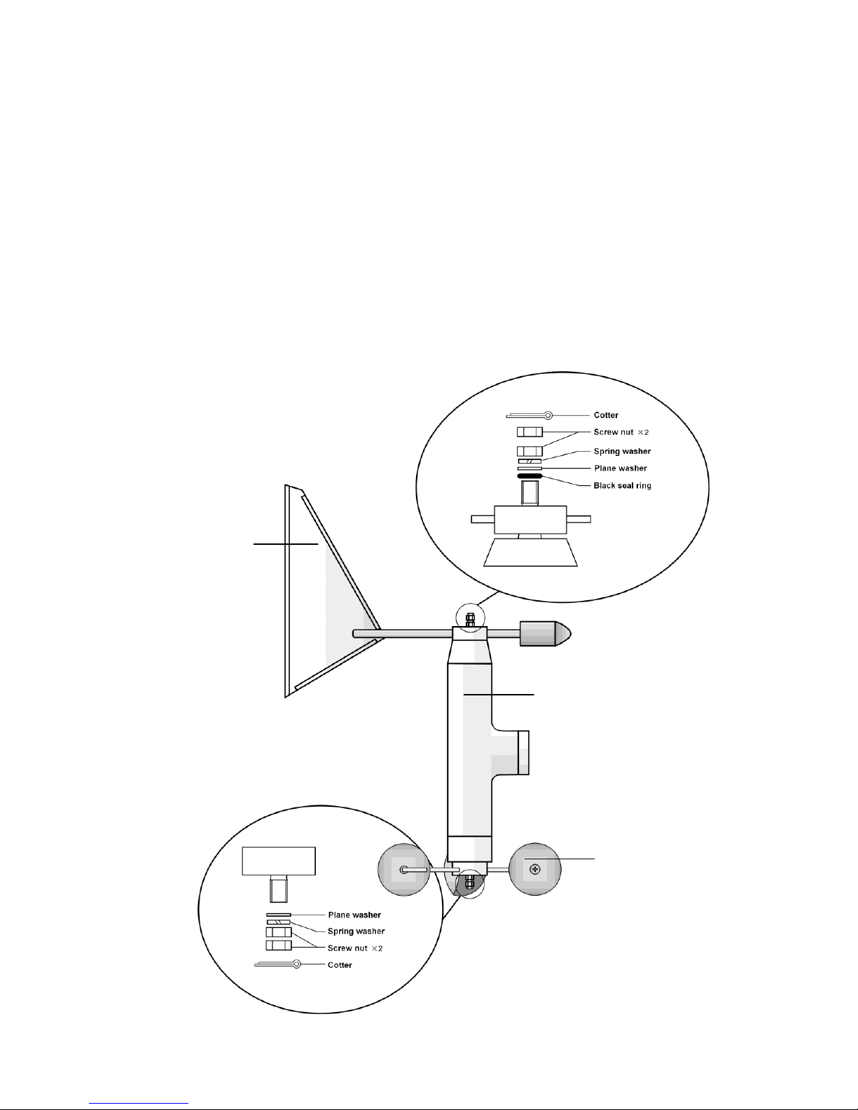
Wind Vane and Wind Cup Installation
[ Wind Vane ] Wind vane is installed on the top of sensor holder,
successively into black seal ring, plane washer, spring washer and 2 screw
nuts. The two screw nuts should be tightened and then insert the cotter.
[ Wind Cup ] Wind cup is installed on the bottom of sensor holder,
successively into plane washer, spring washer and 2 screw nuts. The two
screw nuts should be tightened and then insert the cotter.
Sensor holder
Wind cup
Wind vane
Page 30
25
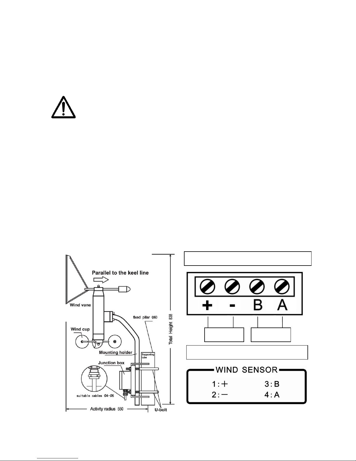
Integral Installation
[ Space and location ] The total height of wind sensor is 838mm. It should
be horizontally installed on the ventilated place of ship and the action radius
of wind indicator and wind cup is over 550mm.
Please note, big Radar antenna rotation can disturb
the wind measurement. Find a location away from
Radar.
[ Integral fixation ] Use U-bolt in the accessory to fix wind sensor and the
best option of supporting tube diameter is 60mm.
[ Wiring ] 4-core screened cable with external diameter 4mm~6mm is
connected with 4 terminals +、-、B、A through glands of junction box.
Please pay attention on wire colors and sequence in order to correctly
connect the wiring terminals of back cover, 1+ 2- 3B 4A.
[ Calibration ] After the installation of main unit of wind sensor, do the
calibration of wind direction based on Calibration.
AM706D back cover terminals
DC
NMEA
AM706S junction box terminals
Page 31
26
Temperature and Humidity Sensor Installation
Temperature and Humidity Sensor AM706TH
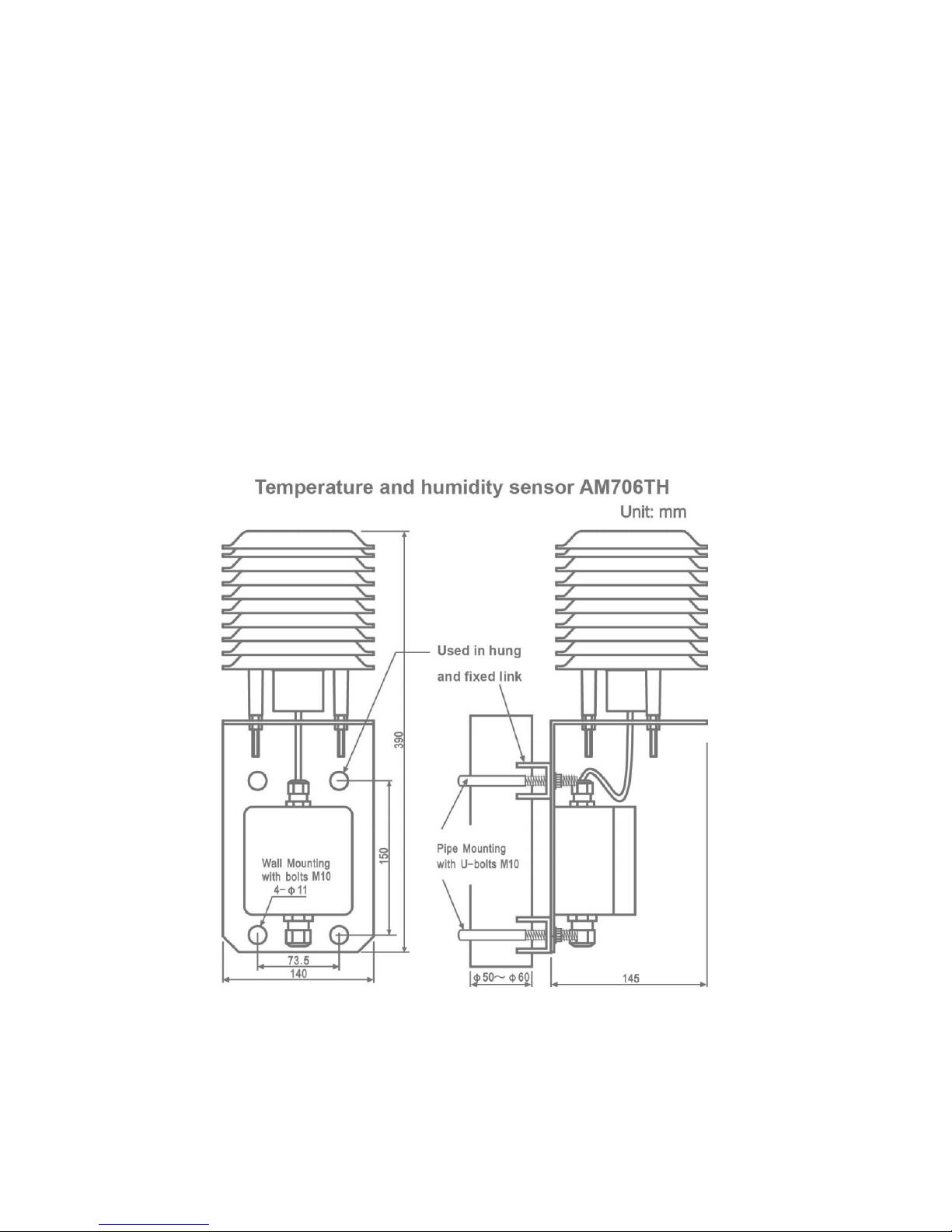
Temperature and humidity sensor AM706THcan be installed in hung and
fixed link mounting methods.
AM706TH with M10 bolt is installed on the vertical wall or with U-blot M10 is
installed over vertical pipe fitting.
Unit:mm
Page 32
27
Wiring explanation
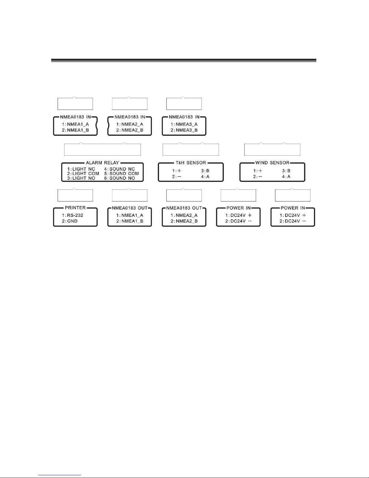
Wiring diagram of AM706D back cover
Page 33

28
System internal connection
System internal wiring diagram
Page 34
29
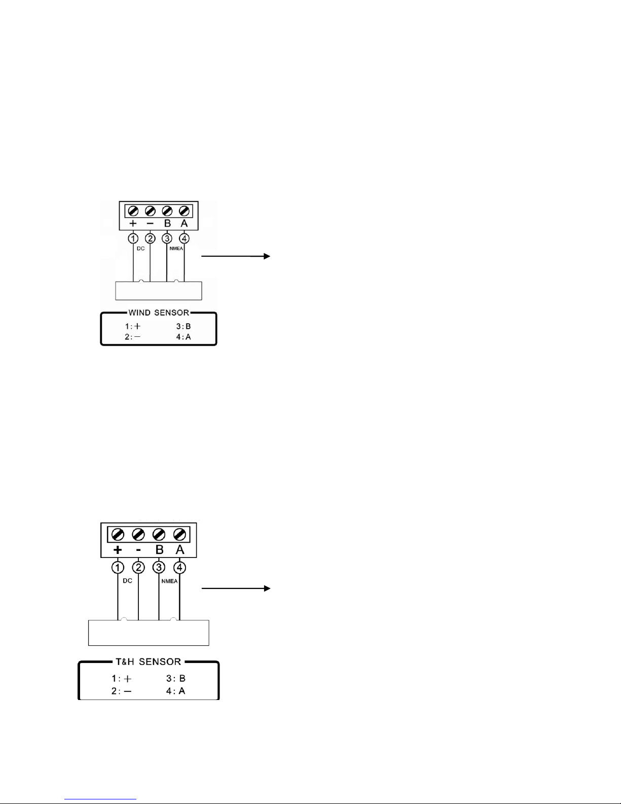
Wind sensor AM706S - Main unit AM706D
4-core screened cable with external diameter 4mm~6mm is connected with 4
terminals +、-、B、A through glands of junction box. Please pay attention on
wire colors and sequence in order to correctly connect the wiring terminals of
back cover, 1+ 2- 3B 4A.
TMP and HUM sensor AM706TH-Main unit AM706D
4-core screened cable with external diameter 3mm~6mm is connected with 4
terminals +、-、B、A through glands of junction box. Please pay attention to
wire colors and sequence in order to correctly connect the wiring terminals of
back cover, 1+ 2- 3B 4A.
4-core screened cable with
external diameter 4-6mm
4-core screened cable with
external diameter 3-6mm
AM706TH internal terminals
AM706D back cover terminals
AM706S internal terminals
AM706D back cover terminals
Page 35
30
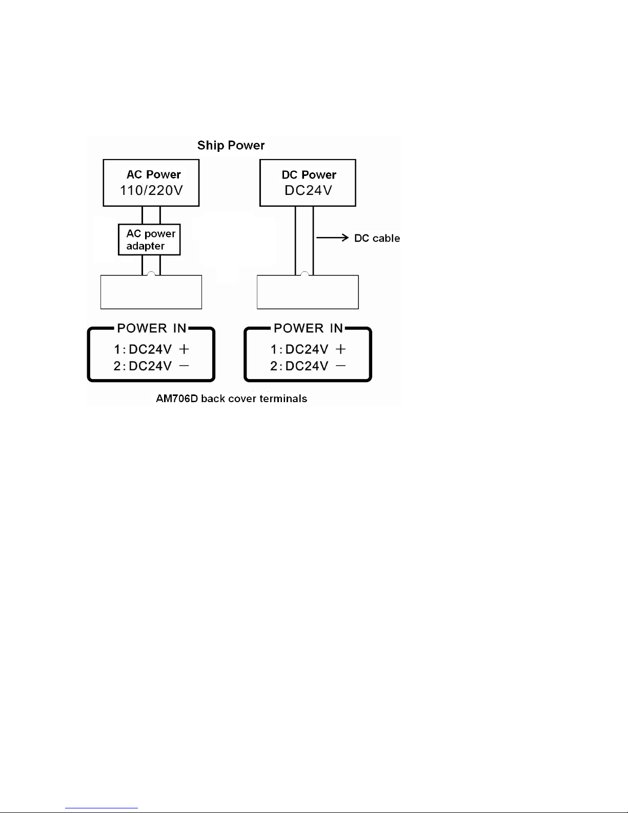
Main unit AM706D Power in
Connect DC cable and ac power adapter (GA-240150) with ship
power.
Page 36
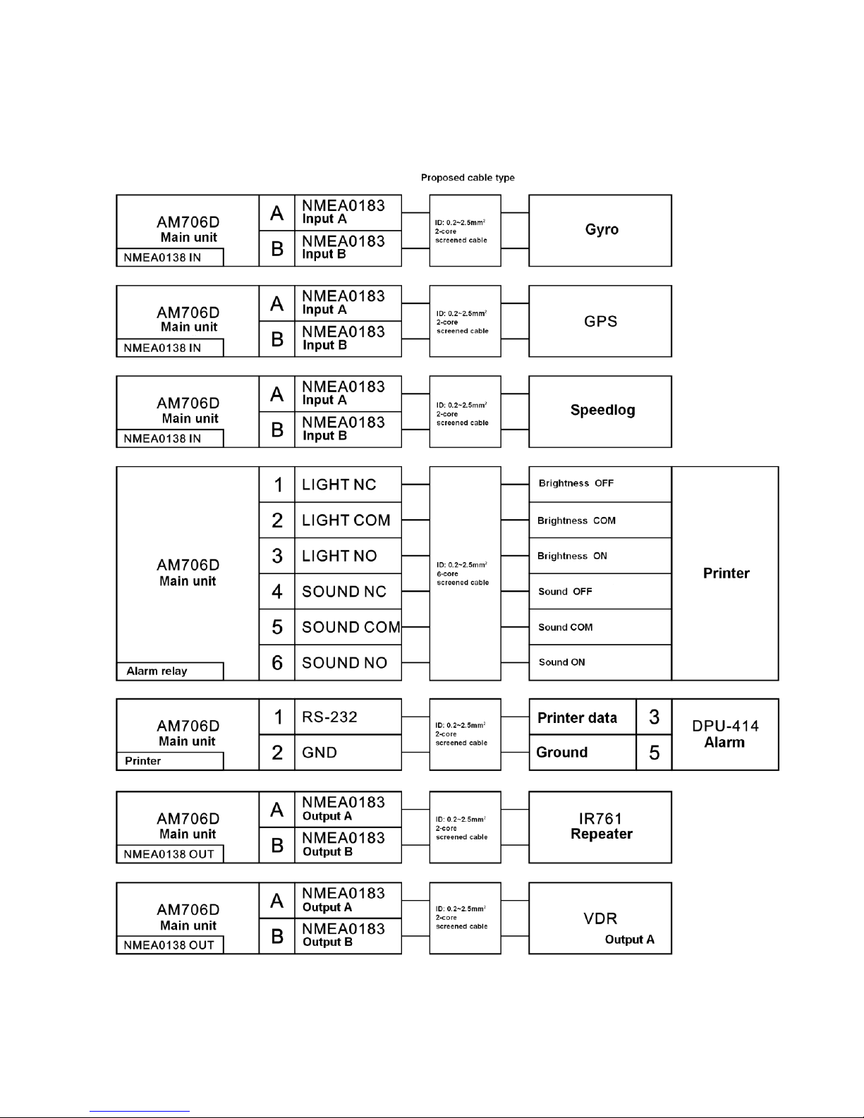
31
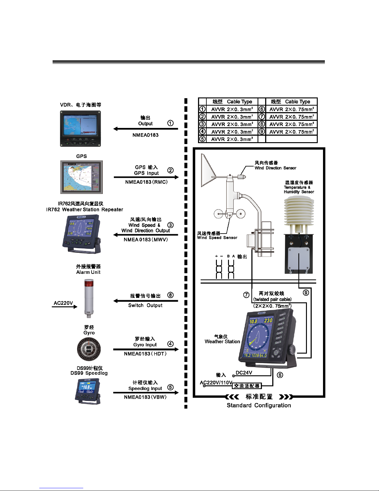
System external connection
System external wiring diagram
 Loading...