

Ningbo Ginlong Technologies Solis-20K, Solis-25K, Solis-30K, Solis-36K-HV, Solis-40K-HV Installation And Operation Manual
...
PV Grid Tie Inverter
Installation and Operation M anual
Ver 1. 3
Solis Three Phase Inverter
2014, N ing bo Gi nlong Technologies C o., L td
C
Ningbo G inl ong Tech nol ogies Co. , Ltd .
No. 57 Jin ton g Road, Bin hai I ndustri al Pa rk, Xiang sha n, Ni ngbo ,
Zhejia ng, 3 15712, P.R. China.
Tel: +86 (0) 574 6 578 1806
Fax: +86 ( 0)5 74 6578 160 6
If you enc ount er an y prob lem on the in vert er, pl ease f ind out the i nver ter S /N
and cont act us , we wi ll try t o resp ond t o your q ues tion AS AP.
For model Solis-20K, Solis-25K, Solis-30 K, Soli s-30K -H E
Solis-36K-HV,So lis-4 0K-H V

Content
.1.
2.3 Notice For Use
3. Overview
3.1 Inverter Interface Instructions
3.2 LED Status Indicator Light
3.3 Keypad
3.4 LCD
4. Product handing and storage
4.1 Product handing
4.2 Product storage
3
5
5
5
6
7
7
7
8
8
9
9
10
1. Introduction
2. Safety Instruction
2.1 Safety Symbols
2.2 General Safety Instruction
……………………………………………………………
……………………………………………………
…………………………………………………
……………………………………
…………………………………………………
……………………………………………………………
…………………………
…………………………………
………………………………………………………
…………………………………
4
1.2 Packaging List
…………………………………………………
……………………………………………………………
4
1.1 Induction
…………………………………………………………
………………………………………………
………………………………………………
5. Installation
5.1 Select a Location for the Inverter
5.2 Mounting the Inverter
5.3 Electrical Connections
6. Start and Stop
6.1 Start the Inverter
6.2 Stop the Inverter
11
11
13
15
23
23
23
…………………………………………………………
………………………
………………………………………
……………………………………
……………………………………………………
………………………………………………
5.3.1 D C si de co nne cti on
5.3.2 AC sid e con nec tio n
16
18
5.3.3 Inverter monitoring connection
20
…………………………………
……………………
…………………………………
7. General Operation
24
………………………………………………
………………………………………………
7.1 Interface
24
………………………………………………………

.2.
.3.
1. Introduction
Sol is thre e phase s eries P V inver ters is a ble to tr ansfe r DC powe r from PV p anels i nto AC
pow er and fe ed into g rid.
The re are 6 mo dels fo r Solis t hree ph ase inv erter :
Sol is-20 K Solis -25K So lis-3 0K Soli s-3 0K-H E
Sol is-36 K-HV So lis-4 0K-HV (HV ref er to 480 V rated g rid vol tage)
Fig ure 1.1 F ront vi ew
Fig ure 1.2 B ottom v iew
7.3 Setting
7.3.1 Setting Time
7.3.2 Setting Address
7.4 Advanced Info - Technicians Only
7.4.1 Alarm Message
7.4.3 Version NO.
7.4.4 Communication Data
7.4.5 Daily Energy Information
7.5 Advanced Settings - Technicians Only
7.5.1 Select Grid Standard
7.5.2 Grid ON/OFF
8. Maintenance
9. Trouble Shooting
10. Specification
27
27
28
30
31
32
33
33
36
36
39
42
42
44
7.4.2 Operational Message
32
7.5.3 Power Setting
39
……………………………………………………
………………………………………
…………………………………
………………………………………
……………………………
……………………………
………………………………………………
……………………………………………
……………………………………
7.3.3 Language Setting
7.3.4 Screen Brightness Control
28
29
7.3.5 System Update
30
7.4.7 Yea rly E ner gy De tai l
7.4.8 Total Energy Detail
7.4.9 Work Log
34
35
35
7.4.6 Monthly Energy Detail
34
……………………………
……………………………………………
……………………………
…………………………
………………………
7.5.5 Calibrate Energy
40
40
7.5.6 Change Password
41
………………………………
………………………………
……
………………………………
……………………………………
……………………
…………………
……………………………………
…………………………
Content
7.5.4 Clear Energy and Restore factory settings
……………
………………………………………
……
…………………………………………………
7.2 Information
26
……………………………………………………
7.1.1 Main Menu
25
……………………………………………

2. Safety Instruction
.5.
2.1Safety Symbols
Safety symbols used in this manual, which highlight potential safety risks and important
safety information, are listed as follows:
CAU TION:
CA UTI ON, R ISK O F EL ECT RIC SHO CK sy mbol i ndi cate s impo rtan t saf ety
ins truct ions, w hich if n ot corr ectly f ollow ed, cou ld resu lt in ele ctric s hock.
CAU TION:
CAU TION, H OT SURFA CE sym bol i ndic ates s afet y instr uctio ns, whi ch if not
cor rectl y follo wed, co uld res ult in bu rns.
NOT E:
NO TE sy mbol i ndic ates i mport ant saf ety ins truct ions, w hich if n ot corr ectly
fol lowed c ould re sult in s ome dam age or th e destr uctio n of the in verte r.
WAR NING :
WA RN ING s ymbol i ndica tes imp ortan t safet y instr uctio ns, whi ch if not c orr ectl y
fol lowed , could r esult i n serio us inju ry or dea th.
Imp roper u se may re sult in p otent ial ele ctric s hock ha zards o r burns . Thi s manua l conta ins
imp ortan t instr uctio ns that s hould b e follo wed dur ing ins talla tion an d maint enanc e. Plea se
rea d these i nstru ction s caref ully be fore us e and kee p them fo r futur e refer ence.
2.2 General Safety Instructions
WAR NING :
Ele ctric al inst allat ions mu st be don e in acco rdanc e with th e local a nd nati onal
reg ulato ry and el ectri cal saf ety sta ndard s.
WAR NING:
DC in put and AC o utput m ust be el ectri cally i solat ed befo re oper ation .
DO NO T con nect PV a rray po sitiv e (+) or ne gativ e (-) to th e groun d. To do
so ma y cause s eriou s damag e to the in verte r.
. .4
1.2 Packaging List
Ple ase che ck acco rding t o follo wing ta ble, to s ee whet her all t he part s were in clude d in the
pac kagin g:
Par t NO.
Des cript ion Num ber
PV gr id tie In verte r
Wal l moun ting b rac ket
Loc king sc rews
Exp ansio n screw s
DC co nnect ors
Adh esi ve tap e
Table 1 .1 Mate rial li st
8 pai rs
Rj4 5 conne ctor
2 set
1. Introduction
1
2
3
4
5
6
7
1
1
2
3
1
PV Grid Tie In verte r
Installati on and Op erati on Manu al
Ver 1.3
Solis Three Phase Inverter
2014, Ningbo Gi nlong Tech nolog ies Co. , Ltd
C
For model Soli s-20K , Solis -25K, S olis- 30K, So lis-3 0K-H E
Solis-36K- HV,Sol is-40 K-HV
Man ual
8
1
8

3. Overview
.6.
.7.
3.1 Inverter Interface Instructions
Fig ure 3.1 F ront Pa nel Dis play
3.2 LED Status Indicator Lights
The re are th ree LED s tatus i ndica tor lig hts in th e front p anel of t he inve rter.
In th e Left: P OWER LE D indic ates th e power s tatus o f the inv erter.
In th e Middl e: OPER ATIO N LED (gr een) in dicat es the op erati on stat us.
In th e Right : ALA RM LED ( yell ow) i ndic ates t he ala rm st atus .
Ple ase see Tab le 3.1 f or deta ils
2. Th e inv erte r must be con nected to a s eparate g rounded AC g roup, to wh ich no
other el ectr ica l equi pme nt is co nne cted
3. Th e ele ctri cal i nsta llation m ust meet al l the appli cable reg ulation s and st and ards .
4. The inv erter mus t be instal led accor ding t o the instr uctions s tate d in th is
manual .
5. Th e inve rte r must b e inst alle d accor ding to t he corr ect tec hnica l speci ficat ions.
2.3 Notice For Use
The i nver ter w as des igne d in ac corda nce wit h relav ant saf ty regu latio n to meet e nd user ’s
dem and. Th e usag e of in vert er and i nsta llati on shou ld meet t he foll owing r equir ement :
WAR NING :
To redu ce the ri sk of fir e, over -curr ent pro tecti ve devi ces (OC PD) are r equir ed
for c ircui ts conn ected t o the Inv erter. T he rec omm ende d rate d trip c urren t of
OCP D, Soli s-20K s hould b e 40A, So lis-2 5K, Sol is-30 K,Sol is-30 K-HE,
Sol is-36 K-HV an d Solis -40K- HV shou ld be 63A .
CAU TION:
Ris k of elec tric sh ock. Do n ot remo ve cove r. Refer m ainte nance s ervic ing to
qua lifie d and acc redit ed serv ice tec hnici an.
CAU TION:
The P V array ( Solar p anels ) suppl ies a DC vo ltage w hen it is e xpose d to ligh t.
CAU TION:
Ris k of elec tric sh ock fro m energ y store d in capa citor s of the In verte r. Do not
rem ove cov er unti l 5 minut es afte r disco nnect ing all s ource s of supp ly. Serv ice
tec hnici an only. Wa rrant y may be vo ided if a ny unau thori zed rem oval of c over.
CAU TION:
The s urfac e tempe ratur e of the in verte r can exc eed 75℃ (1 67F).
To avoi d risk of b urns, D O NOT tou ch the s urf ace wh en inv erte r is oper ating .
The i nvert er must b e insta lled ou t of reac h of chil dren.
1. Secur e inverte r inst all atio n is re quir ed.
6. To sta rtup t he in vert er, the G rid Su pply Ma in Swit ch (AC ) must b e swit ched o n, bef ore
the s olar pa nel's DC is olat or swi tched o n. To stop the i nver ter, th e Gri d Supp ly Mai n
Swi tch (A C) mus t be swi tche d off be fore t he sola r panel 's DC i sola tor sw itch ed off.
7. D C inpu t volt age of i nver ter mus t less th an its ma ximum i nput vo ltage o f inver ter.
2. Safety Instruction

4. Product handing and storage
. .8
.9.
3.3 Keypad
3.4 LCD
The re are f our k eys in t he fro nt pan el of the I nvert er(fr om left t o rig ht): E SC, UP, DO WN
and E NTER ke ys. The k eypa d is us ed for :
Scr ollin g throu gh the di splay ed opti ons (th e Up and th e Down ke ys).
.
The t wo-l ine s Liqu id Cry stal D ispla y (LCD) i s locat ed at the f ront pa nel of th e Inver ter,
whi ch show s the fol lowin g infor matio n:
1. Inve rter o pera tio n stat us and d ata;
2. Serv ice me ssag es fo r oper ator ;
3.A larm me ssage s and fau lt indi catio ns.
Des cript ion
The i nvert er can de tect DC p ower
No DC p ower or l ow DC pow er
The i nvert er is ope ratin g prope rly.
The i nvert er has st opped s upply ing pow er.
The i nvert er is ini tiali zing.
Ala rm or fau lt cond ition i s detec ted.
The i nvert er is ope ratin g prope rly.
Sta tus
ON
OFF
ON
OFF
OFF
ON
FLA SHING
Lig ht
POW ER
OPE RATION
ALA RM
Acc ess to mo dify th e adjus table s ettin gs (the E SC and th e ENTER k eys).
3. Overview
Table 3 .1 Stat us indi cator
4.1 Product handing
Please refer below to handing the product:
1.The red mark is used for handle the product with package. The product need two persons to
carry. (as shown in figure 4.1)
Figure 4.1 move the inverter
2.After open the package, it's recommend two person to get the inverter out of package.
Please handle the side of heat-sink when carry the inverter.(as shown in figure 4.2)
Figure 4.2 carry out the inverter

5.1 Select a Location for the Inverter
To sele ct a loca tion fo r the inv erter t he foll owing c riter ia shou ld be con sider ed:
Do no t insta ll the in verte r in unve ntila ted con fined s pace. To av oid po or perf orman ce
or da mage in verte r, air flo w is need ed.
Exp osure t o direc t sunli ght wil l incre ase the o perat ional t emper ature o f the inv erter
and may cau se outp ut powe r limit ing. Gi nlong r ecomm end inv erter i nstal led to av oid
dir ectsu nligh t or rain ing.
Sha ded or sh elter ed posi tions a re reco mmend ed for ma ximum p erfor mance a nd
ser vice li fe.
Fig ure 5.1 R ecomm ended i nstal latio n posit ion
4. Installation
4.2 Product storage
Please use the original box to repackage the inverter, and retain the desiccant.
Packing boxes should be sealed with adhesive tape.
Storage temperature should be kept at -25℃-60℃,and the relative humidity should be kept
between 0 to 95%.And kept no condensation.
Please avoid the chemical corrosive substances,because it maybe corrod the inverter.
The packing box should not be inclined or upside down.
After long-term storage, the inverter needs to be fully examined and tested by professional
person before using.
If th e inver ter is no t for usi ng at pre sent, i t shoul d be stor ed unde r the spe cific e nviro nment :
Please store the inverter in a clean and dry place, and keep it without the erosion of dust and
vapor.
5. Installation
The maximum cumulative number of layers should not be more than 4 when stack of multiple
inverters.
The regular inspection is needed during the storage. If found the rat bite etc.,should replace the packing
material in time
.11.
.10 .

5.2 Mounting the Inverter
The i nvert er can be m ounte d to the wa ll or met al stru t of modu le. The m ount ing h oles
sho uld be co nsist ent wit h the siz e of the br acket o r the dim ensio ns show s below.
1. Acco rdin g to the f igu re 5.2 , sele ct the m oun ting h eigh t of the b racke t and mar k the
mou nting h oles. F or bric k walls , the pos ition o f the hol es shou ld be sui table f or the
exp ansio n bolts .
2.M AKE SUR E the bracket is hor izon tal and the m ount ing holes A , B, and C ( in
Fig ure 5.3 ) are in the cor rect p oints. Dr illing th e holes on th e wall acco rdin g
the mark s.
WAR NING :
The i nvert er must b e mount ed vert icall y on a vert ical wa ll.
The i nvert er shou ld be mou nted in a v ertic al posi tion. T he ste ps of m ount ing ar e as fol lows:
Fig ure 5.3 T he dim ensio ns of the m oun ting b rack et
3. Usin g the ex pans ion b olts t o fix th e brac ket t o the wa ll.
Ins tall on a v ertic al surf ace or st ructu re capa ble of be aring t he weig ht.
Mus t insta ll vert icall y withi n +/- 5. If t he inve rter is t ilted f rom the v ertic al plan e heat
dis sipat ion can b e inhib ited. T his ma y reduc e syste m perfo rmanc e or redu ce serv ice
lif e of the in verte r.
Visi bility of th e LED statu s indicat or lights and LCD disp lay scree n should be co nsider ed.
NOT E:
The i nvert er must b e insta lled ou t of reac h of chil dren.
A mini mum of 50 0mm cle aranc e is requ ired to p, bott om, lef t and rig ht of the i nvert er
(is olato r enclo sures e xcept ed) for a ir flow a nd cool ing.
500m m
500m m
500m m
500m m 500m m
500m m
500m m
Fig ure 5.2 I nvert er moun ting cl earan ce
A B
C
5. Installation
A sun sh ade is re comme nded to m inimi se dire ct sun ex posur e where a mbien t
tem perat ure may e xceed 4 0℃.
5. Installation
.12 .
.13 .

5. Use M 4*9 sc rews to fix th e bott om of th e in vert er to the m oun t bra cket .
5.3 Electrical Connections
The e lectr ical co nnect ion of th e inver ter mus t follo w the ste ps list ed belo w:
1. Sw itch th e Grid Su pply Ma in Swit ch (AC) O FF. Switc h the DC Sw itch OF F.
2. Co nnect t he inve rter to P V array.
3. Co nnect t he inve rter to t he grid .
The I nver ter i s desi gned w ith qu ick-c onnec t termi nal por t for ele ctric al conn ectio n
wit hout re movin g the cov er. The me anin gs of the s ymb ols at t he bot tom of t he inve rter
are l isted i n Table 5 .1. All el ectri cal ins talla tions m ust be in a ccord ance wi th all lo cal
and n ation al stan dards .
Table 5 .1 Elec trica l conne ction s ymbol s
GRI D
COM 1
Con necti ng term inal of t he Grid
DC 1 in put ter minal
DC 1- D C4
+
_
Pos itive D C input t ermin al
Neg ative D C input t ermin al
DC SW ITCH
Swi tch of DC i nput te rmina ls (opt ional )
Com munic ation p ort for W i-Fi or G PRS sti ck
CO M2、CO M3
Com munic ation p ort of R J45
Fig ure 5.6 F ix the in verte r
4. Lift u p the in vert er, an d make t he hol es on th e bac k brac ket of i nver ter ali gn to the
con vex on th e mount ing bra cket. T hen fi x the i nver ter to t he bra cket sl owly un til it
mou nts wel l (in fig ure 5.5 ).
Fig ure 5.4 F ix the br acket t o the wal l
Fig ure 5.5 F ix the in verte r to the br acket
5. Installation 5. Installation
.14 .
.15 .

iv) I nsert t he cont act pin t o the top p art of th e conne ctor an d screw u p the cap n ut to
the t op part o f the con necto r (as sho wn in Fig ure 5.1 2).
iii ) Crimp t he cont act pin t o the wir e using a p roper w ire cri mper as s hown in F igure 5 .11.
Fig ure 5.1 2 Conne ctor wi th Cap nu t Screw ed on
Fig ure 5.11 C rimp t he co ntac t pin to t he wir e
v) Then connect the DC connectors to the inverter. Small click will confirm connection (as shown
in Figure 5.13).
Fig ure 5.1 3 Conne ct the DC C onnec tors to t he Inve rter
Fig ure 5.7 D C+ Conn ector
Fig ure 5.8 D C- Conn ector
B) Co nnect t he “DC+ ”and “D C-”to t he inpu t termi nals; s ee Figu re 5.7 an d Figur e 5.8.
A) Pl ease ma ke sure t he pola rity of t he outp ut volt age of PV a rray ma tches t he
“DC +”and “ DC-”s ymbol s.
5.3.1 DC side connection
The s teps of a ssemb ling th e DC conn ector s are lis ted as fo llows :
I) St rip off t he DC wi re fo r abou t 7mm, D isas sembl e the con necto r cap nut
(se e Figur e 5.9).
ii) I nsert t he wire i nto the c onnec tor cap n ut and co ntact p in as sho wn in Fig ure 4.1 2.
Fig ure 5.9 D isass emble t he Conn ector C ap nut
Fig ure 5.1 0 Inser t the Wir e into th e Conne ctor Ca p nut and c ontac t pin
5. Installation 5. Installation
.16 .
.17 .
A) Stri p the en d of AC cab le ou ter in sula ting j ack et abo ut 90m m then s trip th e end of ea ch
wir e about 1 5mm. (a s shown i n figur e 5.14)
Fig ure 5.1 4 Strip AC c able
The s teps to a ssemb le the AC grid t ermi nals a re list ed as fol lows:
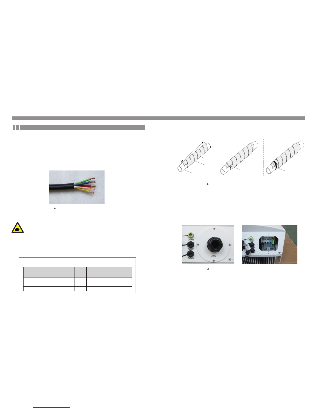
Additional explanation:
If the diameter of the protective layer of the AC cable is less than the recommended
(20K models: 17-25mm;30K models: 21-30mm) it should be spirally wounded the
protective.
The adhesive tape is provided in the accessories.
Winding AC cable in a spiral form.
Please adhesive tape it on the protective layer of AC cables spirally(as shown in figure 5.15).
Figure 5.15 Winding AC cable in a spiral form
8
0
mm~
100
m
m
AC cable
tape
clearance<1.0mm
Please winding after
the clearance of first
layer with the
adhesive tape.
ribbon
In accordance with the actual outer diameter of the protective layer to decide to
wrap one or two layer sealant on the AC cables
layer
14mm~16.9mm
17mm~19.9mm
6
4
80mm~100mm
80mm~100mm
20mm~20.9mm
2
80mm~100mm
10mm~12.9mm
13mm~15.9mm
16mm~16.9mm
,
For a ll AC conn ectio ns, 10- 3 5mm 10 5 ℃ cable i s requi red to be u sed.
2
Ple ase mak e sure th e resis tance o f cable i s lower t han 1.5 o hm. If th e wire is l onger t han
100 m, it's r ecomm ended t o use 16- 35mm c able.
2
5.3.2 AC side connection
The length after winding
AC cable diameter
30K model
AC cable diameter
20K model
①Winding the first
layer
②Winding the second
layer(if needed)
③Please tie the end with
a ribbon or rope
*This picture only supplies the reference,please take the actual product as the standard
B) Disa ssem ble th e 4 scr ews on t he AC ter mina l cov er and t ake ou t the co ver. Dis assem ble
the s crew un der ter minal r ack and P ull out t he term inal. ( as show n in figu re 5.16 )
C) Inse rt the c able t hro ugh cu p nut, w ater p roo f slee ve and AC t ermi nal cov er into t he AC
ter minal a nd use a M6 h exago n screw drive r to tigh t the scr ews. Th e torq ue is 1 0Nm. ( as
sho wn in fig ure 5.1 7)
Fig ure 5.1 6 Disas sembl e AC te rmin al cov er
If th e wire is o ver 10m m , the L1 a nd PE c an be 5m m shor ter th an the L2 , L3, and N . In this
2
way t he L1 and PE ca n be eas ier co nnected to t he con nect or.
5. Installation 5. Installation
.18 .
.19 .

WAR NING :
Ple ase do no t put the i nsula ting la yer of th e cable i n to the te rmina l when ti ght
the s crews , other wise it w ill cau se poor c ontac t.
D) Push the AC terminals along the rail to the inside of the inverter then tighten the screw under rack.
Lock the 4 screws of AC terminal and tighten the cap nut of AC terminal. (as shown in figure 5.18)
5.3.3 Inverter monitoring connection
There are 3 communication terminals for Ginlong 20-40kW inverter. COM1-C OM3 are all for RS485
communication. COM1 is 4-pin connector which matched with the Ginlong Wi-Fi or GPRS wireless
communication products.
COM2 and COM3 are for RJ45 terminal, which is used for communicating connection between
inverters as well as the wired data monitoring.
Figure 5.19 is the internet monitoring solution. Please refer to related instructions of Ginlong
communication products.
Fig ure 5.1 7 Conne ct cabl e to AC term inal
Fig ure 5.1 8 Tig hten t he AC t ermi nal
Rs485 communication connection of RJ 45 ne two rk po rt
1. I nser t the ne twor k cable i nto the c ommun icati on conn ectio n termi nal of R J45.
(As s hown in f igure 5 .21)
Fig ure 5.2 1 RJ4 5 comm unic atio n connecti on ter mina ls
Internet
GPR S monit oring
Wi- Fi moni torin g
Sma rt pho ne mon itor ing
PC mo nitor ing
Web s erve r
Rou ter
Wi- Fi moni torin g
Wi- Fi box
Monitoring system for multiple inverters
The multi-inverters can be monitored by in series of RS485. (As shown in figure 5.20)
多台逆 变器与 电脑或数 据采集器通讯时 时,必须 通过液晶设置通 讯参数。
≈
Inv erter 1 Inv erter 2 Inv erter n
Rs4 85 IN | O UT
Rs4 85 IN | O UT
Rs4 85 IN | O UT
Rs4 85term inal
Rs4 85
Rs2 32
Rs2 32
Eth ernet
Gin long Wi -Fi box
RS48 5-232 conve rter
PC
Rout er
Rs4 85term inal
Gin long G PRS bo x
Int ernet
Int ernet
Fig ure 5.1 9 Inter net mon itori ng solu tion
Fig ure 5.2 0 Multi -inve rters m onito ring sy stem
5. Installation 5. Installation
.20 .
.21 .

2. U se the n etwo rk wir e strip per to st rip the i nsula tion la yer of th e commu nicat ion cab le.
Acc ordin g to the st andar d line se quenc e TIA /EI A 568B, co nnec t the wi re to the plu g of
RJ 45, and t hen use a n etwor k cable c rimpi ng tool t o make it t ight. Am ong the n etwor k
cab les, pi n 1 (whit e and ora nge) an d pin4 (b lue) is f or RS 485 +A ; pin 2 (o range) an d pin 5
(wh ite and b lue) is f or RS 485B . (As sh own in f igure 5 .22)
3. C onne ct the RJ4 5 to CO M2 or C OM3 , and ti ght en the n ut.
Fig ure 5.2 2 Strip t he insu latio n layer a nd conn ect to R J45 pl ug
Fig ure 5.2 3 Tig hten t he nut
Cor respo ndenc e betwe en the
cab les and t he stit ches of p lug
Pin 1 : white a nd oran ge ; Pin 2: o range
Pin 3 : whit e and gr een; Pi n 4: blue
Pin 5 : white a nd blue; P in 6: gre en
Pin 7 : white a nd brow n; Pin 8: br own
Pin 1 w ith 4 and 2 w ith 5 are
use d for com munic ation c onnec tion
Pin 1 a nd 4 are co nnect ed with RS48 5+A
Pin 2 a nd 5 are co nnect ed with RS48 5 - B
1-- 8
Rj4 5 plug
Rj45 termi nal
1 2 34 5 6 7 8
1 2 3 4 56 7 8
R S 4 8 5 +A R S 4 8 5 -B
4. F or the c able s of con necti ng the mo nitor ing dev ice or co nvert er, the in sulat ion of th e
com munic ation c able ne eds to be s tripp ed by a net work wi re stri pper. Co nnect t he
cor respo nded si gnal wi res of R S485 A/ B to the m onit oring dev ice or R S232 c onv erte r.
Pin 1 a nd 4 are de fined a s RS4 85+A wh ile pi n 2 and 5 are def ined a s RS 485 – B.
6.2 Stop the inverter
To stop t he Soli s three p hase st ring in verte r, it is imp ortan t to foll ow the
ste ps here b elow:
1. S witc h the Su pply M ain Swi tch (AC ) OFF.
2. Wa it 10 se conds. Sw itch t he DC sw itc h OFF or d irec tly di sco nnec t the DC o utpu t conne ctor.
The L EDs and L CD of the i nvert er will b e off wit hin on e minut e.
6.1 Start the inverter
To star t up the So lis thr ee phas e strin g inver ter, it is i mport ant to fo llow th e steps h ere bel ow:
1. S witc h the Su pply M ain Swi tch (AC ) ON firs t.
2. Tu rn on th e DC switch o f PV arr ay. If th e volt age of P V array s is high er than t he star t up
vol tage, t he inve rter wi ll turn o n, and th e initi al inte rface o f LCD wil l show “C urren t statu s:
Wai ting ” on the u ppe r left c orne r.
3. Th en the in verte r will ch eck bot h its int ernal p arame ters an d the par amete rs of the
AC an d DC inpu t to ensu re that t hey are w ithin t he acce ptabl e limit s.
4. A fter a roun d 30-1 80 seco nd (bas ed on loc al requ irmen t), the i nvert er will s tart to g enera te
pow er. The gr een LE D will be o n conti nuall y and the L CD disp lays “C urren t statu s:
Gen erati ng.”
Curre nt status: Waiting
Curre nt status: Generating
NOT E:
If tu rn on DC in put swi tch bef ore gri d break er, inve rter ma y show fa ult mes sage
“No _Grid ” on curr ent sta tus, th e fault w ill be cl ear if gr id volt age is no rmal.
6. Start and Stop
5. Installation
.22 .
.23 .

7. General Operation
Dur ing nor mal ope ratio n, the in itial izing L CD show s the cur rent st atus of t he inve rter,
inc ludin g the cur rent po wer, tot al gene ratio n, and th e bar cha rt of pow er oper ation , etc.
Pre ss ESC to s witch f rom the i nitia l inter face to t he deta ils of mo nthly g enera tion.
Pre ss ENTE R to swit ch to the M ain Men u.
sta rt
Curr ent and t otal po wer gen erati on
gene ratio n bar cha rt of the d ay
deta ils of mo nthly g enera tion
inf ormat ion
set tings
adv anced i nfo.
adv anced s ettin gs
UP/ DOWN
UP/ DOWN
UP/ DOWN
Pre ss ESC t o swit ch
Pre ssing t he ENTE R
key t o switc h
to th e subme nu
Pre ssing t he ESC
key c alls ba ck
the p revio us menu
mai n menu
Fig ure 7.1 O perat ion ove rview
7.1 Interface
The i nitia l inter face of t he inve rter sh ows the c urren t opera tion st atus, c urren t power,
gen erati on of the d ay/mo nth/y ear, and t otal ge nerat ion.A nd thro ugh the b ar char t, we
can v iew the g enera tion in forma tion of t he day.
Fig ure 7.2 T he ini tial in terfa ce
Po we r No w Tod ay ’s E ne rg y Mo nt hl y En er gy
25 .00 kW 00 54. 4k Wh 00 491 kW h
Yea rl y E Ne rg y
00 00. 4M Wh
Tot al E ne rg y
00 03. 6M Wh
Status : NO-G rid
201 5-02- 23 19 35
ME NU =< E NT > M ON TH LY E N ER G Y= <E SC >
ES C
UP
DO WN EN T
0:003:00 6:009:0012:0 15:0 18:0 21:0 0:00
00
10
20
30
40
50
60
Po we r[ kW ]
7. General Operation
7.1 .1Main Menu
The re are four s ubmen u in th e Main Menu:
Pre ss the Up or D own ke y to en ter th e inve rter y early, mont hly ener gy det ail s creen . In
the curre nt int erfac e, pre ss the Enter key to move t he cur sor, pr ess th e Up or Down k ey
to v iew ye arly, m onth ly e nerg y deta il.
Fig ure 7.2 Month ly ene rgy de tail
Month ly Energy
201 5-02- 23 19 35
20 15 - -2 3 : 07 1. 2k Wh02
00 0
10 0
20 0
30 0
40 0
50 0
60 0
Mo nt hl y En er gy [k Wh ]
05 10 15 20 25
ES C
UP
DO WN EN T
Fig ure 7.3 Main M enu
Menu
201 5-02- 23 19 35
Inf ormat ion
Set tings
Adv anced Info.
Adv anced S ettin gs
.24 .
.25 .

7.2 Information
The i nvert er LCD provi des ac cess t o oper ation al dat a and i nform ation . Sele ct
"In forma tion" sub men u, turn t he page b y scro lling up or d own.
Fig ure 7.4 I nform ation ( 1)
Fig ure 7.5 I nform ation ( 2)
Infor mtion
201 5-02- 23 19 35
1/ 2
Pow er:
V_DC1:
V_DC2:
V_DC3:
V_DC4:
V_A:
V_B:
V_C:
I_DC1:
I_DC2:
I_DC3:
I_DC4:
I_A:
I_B:
I_C:
300 00W
500 .2V
500 .5V
499 .9V
502 .6V
232 .0V
231 .0V
230 .5V
15. 90A
15. 70A
15. 30A
16. 10A
43. 5A
43. 7A
43. 4A
ES C
UP
DO WN EN T
Infor mtion
201 5-02- 23 19 35
2/ 2
Sta tus:
Total E nergy:
Thi s Year:
Las t Year:
Thi s Month:
Las t Month:
Today:
Yest erda y:
Fre quenc y:
Car bon Off set:
Effi cien cy:
Gen erati ng
000 3687k Wh
000 0014k Wh
000 0001k Wh
050 8kWh
208 1kWh
007 1.6kW h
000 204kW h
50. 01Hz
000 3.67t on
99. 99%
ES C
UP
DO WN EN T
7. General Operation7. General Operation
7.3 Settings
The follo wing i nterf ace are displ ayed w hen th e Sett ings m enu is selec ted, an d pres s the
UP/ DOWN k eys to s elect d iffer ent op tio n, pre ss th e ENT ER key to ente r the sub men u.
7.3.1 Setting Time
Thi s func tion a llows time a nd dat e sett ing. W hen th is fun ction is sel ected ,the L CD wil l
dis play a s scree n as sh own in Figur e 7.7.
Fig ure 7.6 S ettin g
Fig ure 7.7 S ettin g time
Setti ngs
201 5-02- 23 19 35
Set Ti me/Da te
Set Ad dress
Set L angua ge
Bri ghtne ss
Upd ater
Set Time /Date
201 5-02- 23 19 35
NE X T= <E N T> D ON E =< ES C >
MM DDYY
2 232 015
--
HH MM
20 53
:
ES C
UP
DO WN EN T
.26 .
.27 .

7.3.2 Setting Address
Pre ss the UP/DO WN key s to se t the a ddres s. Pre ss the ENTER key to sav e the sett ings .
Thi s func tion i s used to set the ad dress of an i nvert er con necte d to PC for co mmuni catio n
pur pose. The ad dress numbe r can b e assi gned f rom“0 1”to “ 99”(s ee Fig ure 7. 8). Th e
def ault a ddres s numb er of t he inve rter i s “01” .
Fig ure 7.8 Ad dress s ettin g
7.3.3 Language Setting
This fu ncti on i s use d to set th e languag e of inv ert er LC D display.
Pre ss the UP/DO WN key s to se t time and da ta. Pr ess th e ENTE R key t o mo ve fr om on e
dig it to the n ext (fr om left t o right ). Pres s the ESC k ey to sav e the set tings a nd retu rn to th e
pre vious m enu.
Set Add ress
201 5-02- 23 19 35
YE S =< EN T > NO =< E SC >
Slave Address:01
ES C
UP
DO WN EN T
Pre ss the ESC key to ca ncel the c han ge an d ret urn t o the p revio us men u.
7. General Operation 7. General Operation
7.3.4 Screen Brightness Control
Thi s fun cti on is used to set LCD scre en bri ghtn ess .
Fig ure 7.9 L angua ge sett ings
Fig ure 7.1 0 Scree n brigh tness a djust ment
Set Lan guage
201 5-02- 23 19 35
Eng lish
Chi nese
YE S =< EN T > NO =< E SC >
Pre ss the UP/DO WN key s to se t the a ddres s. Pre ss the ENTER key to sav e the sett ings .
Pre ss the ESC key to ca ncel the c han ge an d ret urn t o the p revio us men u.
Pre ss the UP/ DOWN k eys t o set the brig htne ss. P res s the EN TER key to save t he set tings .
Pre ss the ESC key to ca ncel the c han ge an d ret urn t o the p revio us men u.
Brigh tness
201 5-02- 23 19 35
45%
ES C
UP
DO WN EN T
YE S =< EN T > NO =< E SC >
.28 .
.29 .

7.4 Advanced Info - Technicians Only
NOT E:
Pas sword r equir ed – rest ricte d acces s – autho rised t echni cians o nly
Un- autho rised a ccess m ay void t he warr anty.
Sel ect Ad vance d Info f rom mai n menu, t he LCD sc reen sh ow the pa sswor d is nee ded:
Fig ure 7.1 2Ente r a passw ord
7.3.5 System Update
Thi s func tion i s used to view t he curr ent sys tem ver sion.
Fig ure 7.11 S yste m ver sion
Updat er
201 5-02- 23 19 35
The Current HM I Version:08
ES C EN T
CA N CE =< E SC > U PD AT E SY S TE M =< EN T>
Passw ord
201 5-02- 23 19 35
Please Input The Current Password
X X X X
ES C
UP
DO WN EN T
YE S =< EN T > NO =< E SC >
7. General Operation
7. General Operation
The scree n can b e scro lled m anual ly by p ressi ng the UP/DO WN key s.
Pre ssing the EN TER ke y give s acce ss to a subme nu.
7.4.1 Alarm Message
The displ ay sho ws the 10 lat est al arm me ssage s (see Figur e 7.14 ).
Scr eens c an be s croll ed man ually by pre ssing the UP / DOWN keys.
Figure 7 .14 Al arm messa ge
The defau lt pass word is "0010 ", pre ss the DOWN k ey to mov e curso r, pres s the UP key to
cha nge the f igure f or inpu t passw ord, af ter ent ering c orrec t passw ord, th e LCD wil l show as
bel ow:
Fig ure 7.1 3 Adv ance d info rma tion
Adcan ced Info.
201 5-02- 23 19 35
Ala rm Mess age
Run ning Me ssage
Vers ion
Com munic ation D ata
Dai ly Ener gy
Mot hly Ene rgy
Yearl y Energ y
Total ly Ener gy
Dai ly Reco rds
Alarm M essage
201 5-02- 23 19 35
Mes sage
NO -Grid
NO -Grid
NO -Grid
NO -Grid
NO -Grid
Dat e/Tim e
Dat a
02- 23 19:3 5
02- 23 19:3 4
02- 23 19:3 4
02- 23 19:2 4
02- 23 18:2 2
01/ 40
000 0
000 0
000 0
000 0
000 0
ES C
UP
DO WN EN T
.30 .
.31 .

7.4.2 Operational Message
The scree n show s the i ntern al ope ratio n param eters of the inver ter (s ee Fig ure 7. 15).
7.4.3Version No.
The s creen s hows t he har dware v ersio n and t he sof tware versi on of t he inve rter
(se e Figu re 7.1 6).
Fig ure 7.1 6 Hardw are and s oftwa re vers ions
版本号
201 5-02- 23 19 35
Fig ure 7.1 5 Runni ng info rmati on
Runni ng Message
201 5-02- 23 19 35
DC B us Volta ge:
DC B us Half Vo ltage:
Rea ctive P ower Ra tio:
Out put Pow er Limi t:
Con trol Wo rd Sta tus:
Inv erter Tem perat ure:
Sta ndard:
113. 9V
150 .7V
+0. 98
100 %
000 0H
052 .1℃
G59 /3
ES C
Version
201 5-02- 23 19 35
Mod el:
Sof tware Ve r.:43030 207
ES C
7. General Operation 7. General Operation
7.4.4 Communication Data
The scree n show s the i ntern al dat a of th e inve rter ( see Fi gure 7 .17),
whi ch is for s ervic e techn ician s only.
Fig ure 7.1 7 Commu nicat ion dat a
7.4.5 Daily Energy Information
The scree n show s the da ily en ergy de tail o f the i nvert er (se e Figu re 7.1 8)
Pre ss the E nter ke y to move c ursor, press t he UP /DO WN k eys to
sel ect ene rgy pow er deta il of dif fere nt date .
Figure 7 .18 D aily powe r gen eration c apa cit y
Commu nication D ata
201 5-02- 23 19 35
01- 10:
11-2 0:
21- 30:
31- 40:
41- 50:
51- 60:
61- 70:
71- 80:
81- 90:
86 61 A1 0 0 01 50 8A 06 1E 0 0
D5 05 1 E 00 00 00 00 0 0 00 00
00 00 0 0 00 00 00 00 0 0 00 00
09 02 0 0 00 00 00 B8 1 0 C0 00
20 5C 8 0 01 00 00 43 0 0 07 02
01 00 0 4 00 6D 04 E6 0 5 01 00
DC 0 5 1E 00 59 06 1 E 00 D4 03
10 27 0 0 00 00 00 00 0 0 00 00
00 00 0 0 00 00 00 60 0 0 00 00
ES C
Daily E nergy
201 5-02- 23 19 35
20 15 - -2 302
00
10
20
30
40
50
60
Da il y En er gy [k W]
00 :0 0 03 :0 0 0 6: 00 09:0 0 1 2: 00 1 5: 00 18: 00 2 1: 00 00: 00
ES C
UP
DO WN EN T
.32 .
.33 .

7.4.6 Monthly Energy Detail
The scree n show s the in verte r dail y ener gy deta il of di ffere nt mo nth (see Figu re 7. 19).
7.4.7 Yearly Energy Detail
Pre ss the UP/ DO WN k eys to s witc h to view month ly ene rgy of d iffer ent ye ar.
Fig ure 7.1 9 Month ly powe r gener ation d etail s
Fig ure 7.2 0 Ann ual ge nera tin g capa city d etai ls
The scree n show s the in verte r mont hly en ergy de tail o f diffe rent y ear (see Figu re 7. 20).
Month ly Energy
201 5-02- 23 19 35
20 15 - -2 3 : 07 1. 2k Wh02
00 0
10 0
20 0
30 0
40 0
50 0
60 0
Mo nt hl y En er gy [k Wh ]
05 10 15 20 25
ES C
UP
DO WN EN T
Pre ss the E nter ke y to move c ursor, press t he UP /DO WN k eys to
sel ect ene rgy pow er deta il of dif fere nt date .
Yearly Ene rgy
201 5-02- 23 19 35
20 15
0. 0
0. 5
1. 0
1. 5
2. 0
2. 5
3. 0
Yea rl y En er gy [M Wh ]
01 02 03 04 05 0 6 0 7 0 8 0 9 1 0 11 12
00 .5 1
ES C
UP
DO WN EN T
7. General Operation7. General Operation
7.4.8 Total Energy Detail
The scree n show s the in verte r tota l ener gy deta il(se e Figu re 7.2 1)
7.4.9 Work Log
The scree n show s the in verte r work l og, re lated i nform ation i s for Gin long se rvice
tec hnici ans onl y.
Fig ure 7.2 1 Total g enera ting ca pacit y detai ls
Fig ure 7.2 2 Worki ng log
Total ly Energy
201 5-02- 23 19 35
0. 0
0. 5
1. 0
1. 5
2. 0
2. 5
3. 0
Tot al ly E ne rg y[ MW h]
20 06 20 07 2 00 8 200 9 20 10 20 11 2 01 2 201 3 20 14 2 01 5
00 .0 1
Daily R ecords
201 5-02- 23 19 35
Mes sage
28C 0
28C 0
28C 0
28C 0
28C 0
Dat e/Tim e
Dat a
02- 23 19:3 5
02- 23 19:3 4
02- 23 19:3 4
02- 23 19:2 4
02- 23 18:2 2
01/ 40
5E0 0
640 0
620 0
620 0
040 0
ES C
UP
DO WN EN T
.34 .
.35 .

Sel ect gri d stand ard (Fi gure 7 .24)
7.5.1 Select Grid Standard
NOT E:
The "User -Def" funct ion ca n be on ly use d by th e serv ice en ginee r and ch angin g
pro tecti on leve l must be allow ed by t he loc al gri d compa ny.
NOT E:
Thi s is for servi ce tec hnici ans on ly. The in vert er is cu stomize d acco rdin g to th e
loc al stan dard be fore sh ippin g, ther e shoul d be no req uirem ent to se t the
sta ndard .
7.5 Advanced Settings - Te chnic ians On ly
Sel ect Ad vance d Sett ings f rom th e Main Menu t o acce ss the follo wing o ption s:
NOT E:
Thi s funct ion is fo r autho rised t echni cians o nly. Imp rope r acc ess an d oper atio n
may r esult i n abnor mal res ults an d damag e to the in verte r.
Pas sword r equir ed – rest ricte d acces s – autho rised t echni cians o nly
Un- autho rised a ccess m ay void t he warr anty.
Fig ure 7.2 3 Adv ance d sett ing s
Advan ced Set.
201 5-02- 23 19 35
Sel ect Sta ndard
Gri d ON/O FF
Pow er Cont rol
Cle ar Ener gy
Res tore Se tting s
Cal ibrat e
Res et Pass word
7. General Operation7. General Operation
Pre ss the UP /DOWN k eys to se lect th e stand ard (AS 4777, VDE41 05,UL -1741 , G59/3 ,
CQC a nd “Use r-Def ” funct ion). Press t he ENTE R key to co nfirm t he sett ing. Pr ess the
ESC k ey to can cel cha nges an d retur ns to pre vious m enu.
Sel ectin g the Use r-Def s ubmen u will ac cess to t he foll owing s ubmen u (see Fi gure 7. 25):
Fig ure 7.2 4 Selec t natio nal sta ndard s
Fig ure 7.2 5 User- Def
Selec t Standard
201 5-02- 23 19 35
Selec t Standard
G59/3
ES C
UP
DO WN EN T
YE S =< EN T > NO =< E SC >
User- Def
201 5-02- 23 19 35
OV -G-V1:
OV -G-V2:
UN -G-V1:
UN -G-V2:
OV- G-F1:
OV- G-F2:
UN -G-F1:
UN -G-F2:
Sta rtup- T:
440 V
459 V
330 V
299 V
51. 0Hz
52. 0Hz
48. 0Hz
47. 0Hz
060 s
OV -G-V1 -T:
OV -G-V2 -T:
UN -G-V1 -T:
UN -G-V2 -T:
OV -G-F1 -T:
OV -G-F2 -T:
UN -G-F1 -T:
UN -G-F2 -T:
Res tore- T:
1.0 s
0.2 s
1.0 s
0.2 s
1.0 s
0.2 s
1.0 s
0.2 s
060 s
SE LE CT =< E NT > DO NE = <E SC >
.36 .
.37 .

Bel ow is the s ettin g range f or User -Def. You m ay chan ge the li mit man ually b y using
thi s funct ion.
OV -G-V 1: 410 ---5 30V OV -G-F 1: 50. 2-53 Hz(60 .2-63 Hz)
OV -G-V 1-T: 0.1 ---9 S OV-G -F1- T: 0.1 ---9S
OV -G-V 2: 430 ---5 80V OV -G-F 2: 51- 53Hz (61-6 3Hz)
OV -G-V 2-T: 0.1 ---1 S OV-G -F2- T: 0.1 ---9S
UN -G-V 1: 300 ---3 60V U N-G -F1: 4 7-49 .5Hz( 57-59 .5Hz)
UN -G-V 1-T: 0.1 ---9 S UN -G-F 1-T: 0.1 ---9 S
UN -G-V 2: 230 ---3 30V U N-G -F2: 4 7-49 Hz(57 -59Hz )
UN -G-V 2-T: 0.1 ---1 S UN -G-F 2-T: 0.1 ---9 S
Pre ss the UP /DOWN k eys to sc roll th rough i tems. P ress th e ENTER k ey to edi t the
hig hligh ted ite m. Pres s the UP/ DOWN ke y again t o chang e the set ting. P ress th e
ENT ER key to s ave the s ettin g. Pres s the ESC k ey to can cel the c hange a nd retu rn
to th e previ ous men u.
NOT E:
The i nitia l value o f the Use r-Def s tanda rd are fo r refer ence on ly. It doe s
not r epres ents th e corre ct valu e suita ble for u se.
Fig ure 7.2 6 Save / ca ncel
Save/ Cancel
201 5-02- 23 19 35
Sav e & Send
Can cel & Exi t
YE S =< EN T > NO =< E SC >
7. General Operation7. General Operation
Thi s funct ion is us ed to sta rt or sto p the gen erati on of the i nvert er (see F igure 7 .27).
Pre ss the DO WN key to m ove the c ursor, P ress th e UP key to r evis e the v alue .
Pre ss the EN TER key t o execu te the se tting .
Pre ss the ES C key to re turn to t he prev ious me nu.
Fig ure 7.2 7 Set Gri d ON/OF F
7.5.2 Grid ON/OFF
7.5.3 Power Setting
Act ive and r eacti ve powe r can be se t throu gh powe r setti ng butt on.
Fig ure 7.2 8 Power s ettin g
Grid O N/OFF
201 5-02- 23 19 35
Gri d ON
Gri d OFF
YE S =< EN T > NO =< E SC >
Power C ontrol
201 5-02- 23 19 35
Outp ut Powe r Contr ol
Reac tive Po wer Con trol
Outp ut Powe r Cortr ol With R estor e
Reac tive Po wer Con trol Wi th Rest ore
.38 .
.39 .

Fig ure 7.2 9 Setti ng the to tal gen erati ng capa city
Adjus ting total g enerati ng power
201 5-02- 23 19 35
Total gene rati ng pow er: 0 00261 6kWh
7.5.5 Calibrate Energy
By us ing our d ata mon itori ng hard ware, t he data o n monit oring w ebsit e can aut omati cally
syn chron ize wit h the pre set tot al gene ratin g power o f inver ter.
War rant y or mai nte nanc e may re sult i n res etin g tota l gene ratin g data, t his fun ction a llow
the m ainte nance p erson nel to am end the t otal ge nerat ing dat a of repl aceme nt inve rter to
the o rigin al one.
7.5.4 Clear Energy and Restore Factory Settings
Cle ar Ener gy can re set the h istor y yield o f inver ter, res tore fa ctory s ettin gs mean s all the
set tings a re rest ored to d efaul t setti ngs.
The se two fu nctio ns are ap plica ble by ma inten ance pe rsonn el only, w rong
ope ratio n will pr event t he inve rter fr om work ing pro perly.
Thi s funct ion is ap plica ble by ma inten ance pe rsonn el only, w rong o perat ion
wil l preve nt the in verte r from re achin g maxim um powe r.
Pre ss the DO WN key to m ove the c ursor, P ress th e UP key to r evis e the v alue . Pres s the
ENT ER key to e xecut e the set ting. P ress th e ESC key t o retur n to the pr eviou s menu.
ES C
UP
DO WN EN T
YE S =< EN T > NO =< E SC >
7. General Operation 7. General Operation
Cal ibrat e
7.5.6 Change Password
Fir st ente r the cur rent pa sswor d, Pres s the DO WN ke y to mov e the cu rsor, pr ess the
UP k ey to re vis e the pa sswo rd fig ure .
Aft er ente ring th e corre ct pass word, y ou can cr eate a ne w passw ord.U pon con firmi ng
the n ew pass word, p ress th e ENT ER ke y to exe cute t he set tin g.(S ee Fig ure 7. 31).
Fig ure 7.3 0 Passw ord set ting
Fig ure 7.3 1 Setti ng new pa sswor d
Passw ord
201 5-02- 23 19 35
Please Input The Current Password
X X X X
ES C
UP
DO WN EN T
YE S =< EN T > NO =< E SC >
Reset P assword
201 5-02- 23 19 35
Please Input New Password
X X X X
ES C
UP
DO WN EN T
YE S =< EN T > NO =< E SC >
.40 .
.41 .

Not e:
Nev er use an y solve nts, ab rasiv es or cor rosiv e mater ials to c lean th e inver ter.
CAU TION:
Do no t touch t he surf ace whe n the inv erter i s opera ting. S ome par ts may be h ot
and c ause bu rns. Tur n OFF the i nvert er (ref er to Sec tion 6. 2) and le t it cool d own
bef ore you d o any mai ntena nce or cl eanin g of inve rter.
The L CD and th e LED sta tus ind icato r light s can be cl eaned w ith clo th if the y are too d irty
to be r ead.
The i nvert er has be en desi gned in a ccord ance wi th inte rnati onal gr id tied s tanda rds for
saf ety, and e lect rom agne tic co mpat ibili ty requ ireme nts. Be fore de liver ing to th e custo mer
the i nvert er has be en subj ected t o sever al to ens ure it’ s opti mal o pera tion a nd rel iabil ity.
Sol is thre e phase s tring i nvert er does n ot requ ire any r egula r maint enanc e. Howe ver, cle an the
hea t-sin k will he lp inve rter di ssipa ting he at and in creas e the lif e time of i nvert er.The d irt on th e
inv erter c an be cle aned wi th a soft b rush.
9. Trouble Shooting
In ca se of a fai lure th e LCD scr een wil l displ ay an ala rm mess age. In t his cas e the inv erter
may s top fee ding en ergy in to the gr id. The a larm d esc ript ions a nd the ir corr espon ding al arm
mes sages a re list ed in Table 9 .1:
8. Maintenance
Ala rm Mess age
OV- G-V
UN -G-V
OV- G-F
UN -G-F
NO -Grid
G- PHA SE
G-F -FL U
OV- G-I
UN B-B US
OV- DC
OV- BUS
UN -BU S
UN B2-B US
Ala rm Desc ripti on
Gri d Over Vol tage
Gri d Under Vo ltage
Gri d Over Fr equen cy
Gri d Under F reque ncy
No Gr id
Gri d Unbal ance
Gri d Frequ ency Fl uctua tion
Gri d Over Cu rrent
DC B us Unba lance
DC O ver Volt age
DC B us Over Vo ltage
DC B us Unde r Voltag e
DC B us Unba lance 2
OV- DCA -I
OV- DCB -I
DC -IN TF.
GR ID- INT F.
IN I-FA ULT
OV- TEM
GR OUN D-FA ULT
Rel ay-FA ULT
DS P-B- FAU LT
DC Inj- FAU LT
12P ower- FAU LT
IL eak-C heck
AF CI- Chec k
AR C- FA ULT
DC (Chan nel A ) Over Cu rrent
DC (Chan nel B ) Ove r Curre nt
DC O ver Cur rent
The G rid Int erfer ence Pr otect ion
The DSP I nitial Pr otec tion
Tempe ratur e Prote ction
Gro und Fau lt
Rel ay Prot ectio n
DS P_B Pr otec tion
DC I nject ion Pro tecti on
12V U nder Vol tage Fa ulty
Lea kage Cu rrent C heck Pr otect ion
AF CI Ch eck Fa ult
AF CI Fa ult
Table 9.1 Ala rm me ssage and d esc ription
9. Trouble Shooting
.42 .
. .43

9. Trouble Shooting
NO TE:
If th e inver ter dis plays a ny alar m messa ge as lis ted in Tabl e 9.1; p lea se tur n
off t he inv ert er (re fer to S ecti on 6.2 to s top you r inver ter) an d wait fo r 5 minut es
bef ore res tarti ng it (re fer to Se ction 5 .1 to sta rt your i nvert er). If t he fail ure
per sists , pleas e conta ct your l ocal di strib utor or t he serv ice cen ter. The b elow
tha t we will n eed so th at we can a ssist y ou.
1. Se rial nu mber of t he Inve rter;
2. Th e dis trib utor /dea ler of th e Inver ter (if a vai labl e);
3. I nsta llat ion da te.
4. Th e des crip tion o f prob lem (i. e. the al arm mes sage di splay ed on the LCD and th e
sta tus of th e LED s tat us ind icat or lig hts . Othe r read ings o btain ed from t he Info rmati on
sub menu (r efer to S ectio n 7.2) wi ll also b e helpf ul.);
5. Your c ontac t detai ls.
10. Specification
.44 .
. .45
Ope ratin g Range U tilit y Frequ ency
Mod el
The m ax DC inp ut volt age
MPP T opera tion ra nge
Max d c input c urren t
Num ber of MP PT/st rings p er MPPT
Rat ed outp ut powe r
Rat ed grid v oltag e
The g rid vol tage ra nge
Ope ratio n phase
Rat ed grid o utput c urren t
Out put pow er fact or
The d c injec tion cu rrent
Rat ed grid f reque ncy
Max . Effic iency
Pro tecti on
Siz e(mm)
Wei ght
Topol ogy
Int ernal c onsum ption
Ope ratin g tempe ratur e
Ing ress pr otect ion
Int erfac e
Des ign lif etime
Uti lity Mo nitor ing
Ope ratio n Surro undin gs Humi dity
EMC
100 0V
4/8
380 V
304~4 60Vac( adjus table )
Thr ee phas e
>0. 99
<50 mA
50/ 60Hz
98. 4%
Tran sform erles s
-25~6 0℃
IP6 5
Rs4 85 WIFI G PRS(O ption al)
>20 years
47- 52 or 57- 62Hz
0~95%
EN6 1000- 6-1:2 007
EN6 1000- 6-3:2 007
Sol is-20 K
200~8 00V
20k W
28. 7A
57. 2kg
<1W (Nigh t)
DC re verse -pola rity; AC s hort ci rcuit p rotec tion;
Isl andin g prote ction ; tempe ratur e prote ction ;Ligh tning p rotec tion
Isl andin g prote ction , VA C FA C in acco rdance w ith UL 17 41,
G59 /3, AS4 777, VD E 0126- 1-1, VD E 4105, C EI 0-21 , CQC
Gri d curre nt THD
<3%
18+ 18+18 +18Ad c
The m ax DC in put pow er
23k W
Sta rting -up inp ut volt age
350 V
530 W*688H* 356.5 D
Sol is-25 K
25k W
36. 1A
28k W
58. 2kg

10. Specification10. Specification
100 0V
4/8
380 V
304~4 60Vac( adjus table )
>0. 99
<50 mA
50/ 60Hz
98. 5%
-25~6 0℃
IP 65
0~95%
EN 61000 -6-1: 2007
EN 61000 -6-3: 2007
Sol is-30 K
200~8 00V
30k W
43. 3A
<3%
18+ 18+18 +18Ad c
34k W
350 V
530 W*700H* 356.5 D
58. 2kg
Ope ratin g Range U tilit y Frequ ency
Mod el
The m ax DC in put vol tage
MP PT ope ratio n range
Max d c input c urren t
Num ber of M PPT /stri ngs per MPP T
Rat ed outp ut powe r
Rat ed grid v oltag e
The g rid vol tage ra nge
Ope ratio n phase
Rat ed grid o utput c urren t
Out put pow er fact or
The d c injec tion cu rrent
Rat ed grid f reque ncy
Max . Effic iency
Pro tecti on
Siz e(mm)
Wei ght
Topol ogy
Int ernal c onsum ption
Ope ratin g tempe ratur e
Ing ress pr otect ion
Int erfac e
Des ign lif etime
Uti lity Mo nitor ing
Ope ratio n Surro undin gs Humi dity
EM C
Gri d curre nt THD
The m ax DC in put pow er
Sta rting -up inp ut volt age
Thr ee phas e
Tran sform erles s
Rs4 85 WI FI GP RS( Optio nal)
47- 52 or 57- 62Hz
<1W (Nigh t)
DC r evers e-pol arity ; AC shor t circu it prot ectio n;
Isl andin g prote ction ; tempe ratur e prote ction ;Ligh tning p rotec tion
Isl andin g prote ction , VA C FA C in acco rdance w ith UL 17 41,
G59 /3, AS4 777, V DE 012 6-1-1 , VDE 4 105, CE I 0-21 , CQC
>20 years
.46 .
. .47
100 0V
380 V
304~4 60Vac( adjus table )
>0. 99
<50 mA
50/ 60Hz
-25~6 0℃
IP 65
0~95%
EN 61000 -6-1: 2007
EN 61000 -6-3: 2007
30k W
43. 3A
<3%
34k W
530 W*700H* 356.5 D
Ope ratin g Range U tilit y Frequ ency
Mod el
The m ax DC in put vol tage
MP PT ope ratio n range
Max d c input c urren t
Num ber of M PPT /stri ngs per MPP T
Rat ed outp ut powe r
Rat ed grid v oltag e
The g rid vol tage ra nge
Ope ratio n phase
Rat ed grid o utput c urren t
Out put pow er fact or
The d c injec tion cu rrent
Rat ed grid f reque ncy
Max . Effic iency
Pro tecti on
Siz e(mm)
Wei ght
Topol ogy
Int ernal c onsum ption
Ope ratin g tempe ratur e
Ing ress pr otect ion
Int erfac e
Des ign lif etime
Uti lity Mo nitor ing
Ope ratio n Surro undin gs Humi dity
EM C
Gri d curre nt THD
The m ax DC in put pow er
Sta rting -up inp ut volt age
Thr ee phas e
Tran sform erles s
Rs4 85 WI FI GP RS( Optio nal)
47- 52 or 57- 62Hz
<1W (Nigh t)
DC r evers e-pol arity ; AC shor t circu it prot ectio n;
Isl andin g prote ction ; tempe ratur e prote ction ;Ligh tning p rotec tion
Isl andin g prote ction , VA C FA C in acco rdance w ith UL 17 41,
G59 /3, AS4 777, V DE 012 6-1-1 , VDE 4 105, CE I 0-21 , CQC
>20 years
Sol is-30 K-HE
600 V
575~8 50V
52. 2Adc
1/8
99. 0%
50k g

100 0V
4/8
>0. 99
<50 mA
50/ 60Hz
98. 6%
-25~6 0℃
IP 65
0~95%
EN 61000 -6-1: 2007
EN 61000 -6-3: 2007
200~8 00V
43. 3A
<3%
Sol is-36 K-HV
36k W
18+ 18+18 +18Ad c
350 V
41k W
530 W*700H* 356.5 D
58. 2kg
480 V
384~5 76Vac( adjus table )
Thr ee phas e
Tran sform erles s
Rs4 85 WI FI GP RS( Optio nal)
47- 52 or 57- 62Hz
<1W (Nigh t)
DC r evers e-pol arity ; AC shor t circu it prot ectio n;
Isl andin g prote ction ; tempe ratur e prote ction ;Ligh tning p rotec tion
Isl andin g prote ction , VA C FA C in acco rdance w ith UL 17 41,
G59 /3, AS4 777, V DE 012 6-1-1 , VDE 4 105, CE I 0-21 , CQC
>20 years
Ope ratin g Range U tilit y Frequ ency
Mod el
The m ax DC in put vol tage
MP PT ope ratio n range
Max d c input c urren t
Num ber of M PPT /stri ngs per MPP T
Rat ed outp ut powe r
Rat ed grid v oltag e
The g rid vol tage ra nge
Ope ratio n phase
Rat ed grid o utput c urren t
Out put pow er fact or
The d c injec tion cu rrent
Rat ed grid f reque ncy
Max . Effic iency
Pro tecti on
Siz e(mm)
Wei ght
Topol ogy
Int ernal c onsum ption
Ope ratin g tempe ratur e
Ing ress pr otect ion
Int erfac e
Des ign lif etime
Uti lity Mo nitor ing
Ope ratio n Surro undin gs Humi dity
EM C
Gri d curre nt THD
The m ax DC in put pow er
Sta rting -up inp ut volt age
.48 .
Sol is-40 K-HV
45k W
40k W
48. 1A
10. Specification
 Loading...