

Page 1
Ningbo Putian Communication Technology Co., Ltd
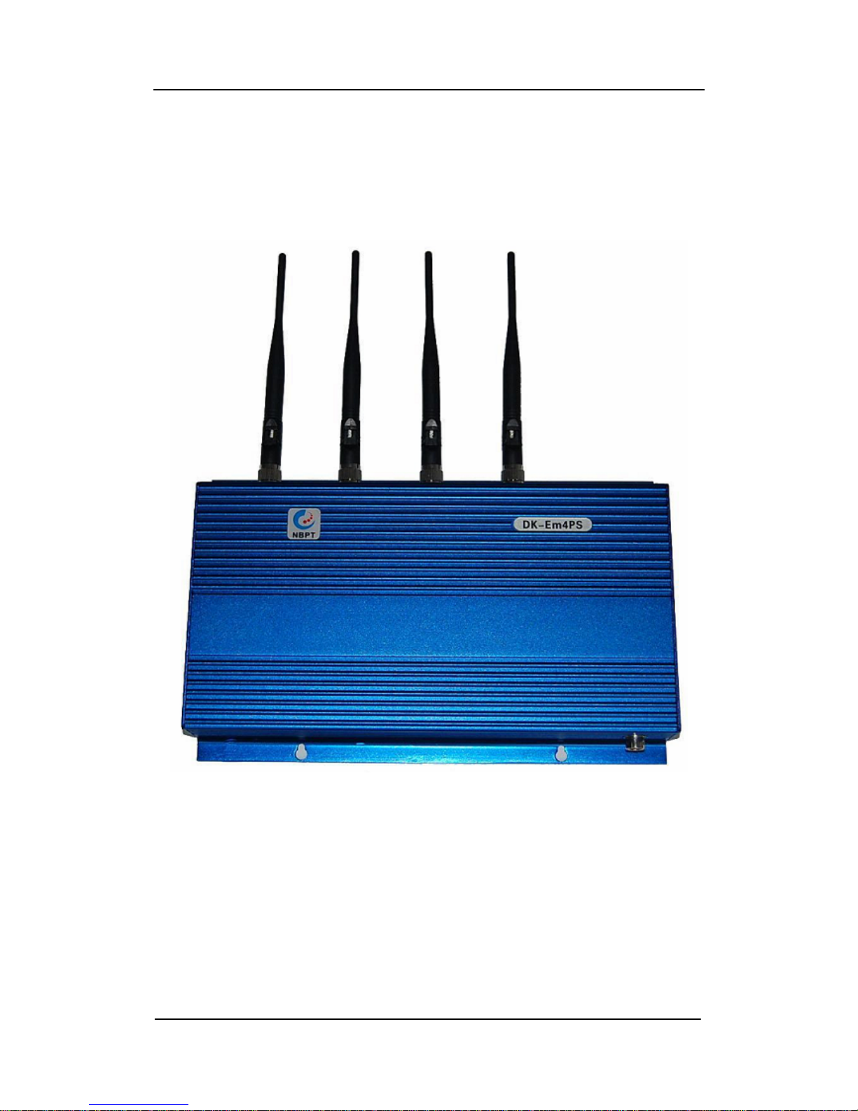
DK-Em4PS
Instruction for DK-Em4PS Auto-dial testing
Device
- 1 -
Page 2

Ningbo Putian Communication Technology Co., Ltd
Ningbo Putian Communication Technology Co., Ltd
Table of Contents
1、OVERVIEW.......................................................................................................................... 3
2、PERFORMANCE AND CHARACTERISTICS FOR PRODUCTS....................................... 4
2.1. BASIC FUNCTIONS AND FEATURES........................................................................... 4
2.2. OPERA TION MODE FOR COMMUNICATION ..............................................................4
3、PERFORMANCE INDICATORS FOR ALL KINDS OF CHANNEL....................................5
4、PERFORMANCE INDICATORS FOR DEVICE................................................................... 6
5、DESCRIPTION FOR DK-EM4PS INSTALLATION............................................................. 7
5.1. ANTENNA INST ALLA TION............................................................................................. 7
5.2. POWER CONNECTION................................................................................................. 7
5.3. USB CABLE CONNECTION........................................................................................... 8
5.4. NETWORKING ............................................................................................................... 9
5.5. INDICATOR DESCRIPTION........................................................................................... 9
5.6. CASE SIZE ..................................................................................................................... 9
6、INSTRUCTION FOR DK-EM4PS DEVICE........................................................................ 10
6.1. DESCRIPTION FOR SIM CARD INSTALLATION........................................................ 10
6.2. DESCRIPTION FOR APPLIC ATION PROGRAM INSTALLATION .............................. 14
6.4. DESCRIPTION FOR APPLICATION PROGRAM'S USE............................................. 18
6.5. NOTES..........................................................................................................................20
7、FCC STATEMENT............................................................................................................. 21
- 2 -
Page 3

Ningbo Putian Communication Technology Co., Ltd
1、Overview
D K-Em4PS Auto-dial testing Device is a Wireless Test Product based
on Mobile communication network platform, this product is tested up to 4
channels embedded。 Test channel can be configured according to test
requirements. including 2 channels for GSM and 2 channels for TD-SCDMA.
The device adopts standard design of industrial-grade, with English and
Chinese SMS sending, voice and wireless data mode functions and etc.
Users can connect with PC by USB2.0 port & Ethernet Interface。This
device can be widely used in monitoring for mobile network coverage。
- 3 -
Page 4

Ningbo Putian Communication Technology Co., Ltd
2、Performance and Characteristics for products
2.1. Basic functions and features
2.1.1. Extend up to 4 test channels, reality a multi-channel for voice, data,
wireless transmission function between different Signal System mobiles。
2.1.2. Testing Communication & test channel for 4 channels can be configured
according to any requirement。
2.1.3.Support GSM Module, can be Transmit with 4 different Signal System
channel,。
2.1.4. ARM11 Processor Embedded can carry on management of
multi-channels & Switching Control;
2.2. Operation mode for Communication
2.2.1.USB port: This port can carry out High-Speed Communication between
local computers, data dial, voice, SMS functions and etc.
2.2.2. Ethernet Interface: this interface supply connection between device and
computers, is used for Configuration of device parameters and functions, it is
easy to maintenance device。
- 4 -
Page 5

Ningbo Putian Communication Technology Co., Ltd
3、Performance Indicators for all kinds of channel
Performance Indicators for GSM channel Module
Basic
characteristics
Description
remark
Signal System
GSM
Default
Configuration
Frequency band
850/900/1800/1900MHz
Transmit Power
Class 4 (+33dBm ± 2dB) for EGSM850
Class 4 (+33dBm ± 2dB) for EGSM900
Class 1 (+30dBm ± 2dB) for GSM1800
Class 1 (+30dBm ± 2dB) for GSM1900
Class E2 (+27dBm ±3dB) for GSM 850 8-PSK
Class E2 (+27dBm ±3dB) for GSM 900 8-PSK
Class E2 (+26dBm +3 /-4dB) for GSM 1800 8-PSK
Class E2 (+26dBm +3 /-4dB) for GSM 1900 8-PSK
Data
Transmission
GPRS:
Multislot Class 12
Full PBCCH support
Mobile Station Class B
Coding Scheme 1-4
EGPRS:
Multislot Class 10
Mobile Station Class B
Modulation and Coding Scheme MCS 1-9
CSD:
V.110, RLP, non-transparent
2.4, 4.8, 9.6, 14.4kbps
USSD:
PPP-stack for GPRS data transfer
SMS
MT, MO, CB, Text and PDU mod
SMS storage: SIM card
Support transmission of SMS alter
User can choose preferred mode.
SIM card
Supported SIM card: 1.8V ,3V
External
antenna
Connected via 50 Ohm antenna connector or antenna pad
- 5 -
Page 6

Ningbo Putian Communication Technology Co., Ltd
4、Performance Indicators for device
Type DK-Em4PS
Power Supply of Module
(10~30)V DC
Power Supply
(85~264)V AC 50/60Hz (Adapter)
Grounding earthing of casing
System power
<20W
Case Size
290mm*190mm*45mm
Case design Vibratio n、Drop resistance 、Waterproof
Specifications
Mean Time Between Failure
≥10000 hours
Others
Work Temperature
≥-10℃,≤+55℃
Storage temperature
≥-20℃,≤+65℃
Normal humidity
≤95%
Work atmosphere
≥62 kPa,≤106kPa
- 6 -
Page 7
Ningbo Putian Communication Technology Co., Ltd
5、Description for DK-Em4PS Installation
5.1. Antenna Installation
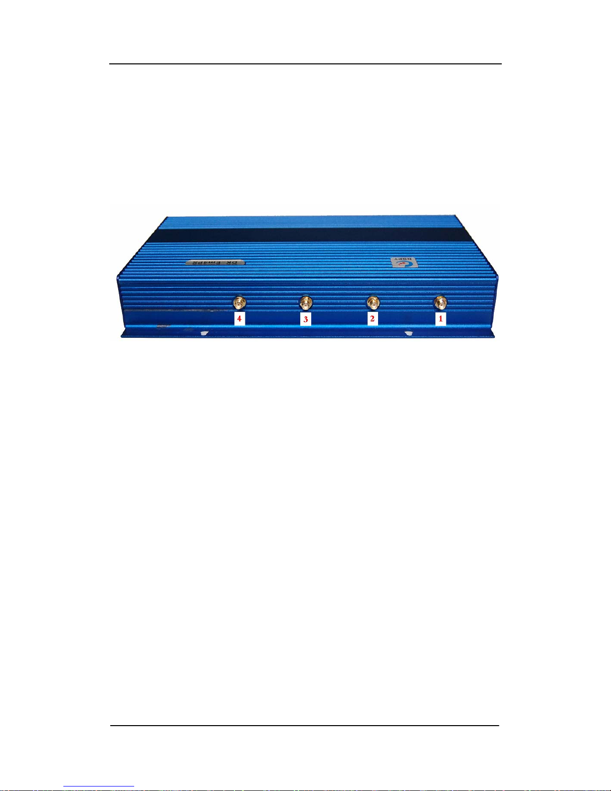
There are 4 SMA port s at the top of a device; users inst all Antenna with
different Module Configurations according to channels and 1-4 Numerical
order on it。As shown in Figure 5-1-1:
Figure 5-1-1 Location of Antenna installation
Note:The antenna must be installed before a device switched on!
Otherwise, the module may be damaged!
5.2. Power Connection
Insert an Adapter into AC220V (different adapters for different counties)
Power Line, then insert into an Outlet, finally a 12V output is connected
with the power interface. When the output of an adapter is inserted into the
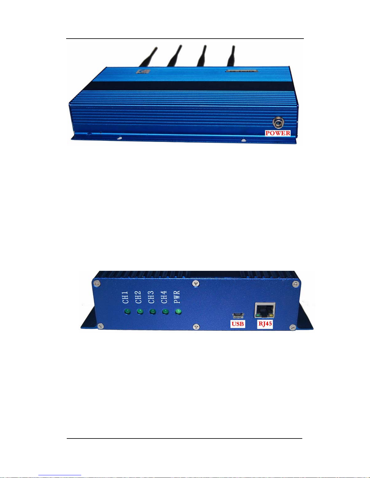
power interface, a device will Open automatically。The position for a Power
Interface as shown in Figure 5-2-1:
- 7 -
Page 8
Ningbo Putian Communication Technology Co., Ltd
- 8 -
Figure 5-2-1 Power Interface
5.3. USB cable connection
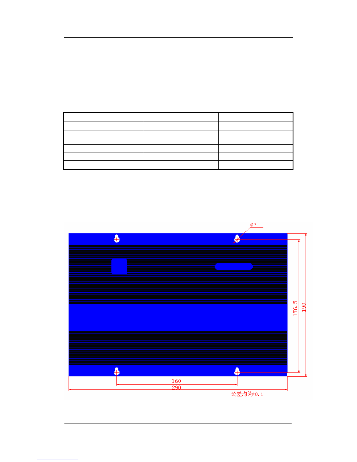
One end of the USB cable is inserted into the device USB interface,
the other end connected to a network。It is used for Data transmission and
control of DK-Em4PS Device。USB port is shown in Figure 5-3-1:
Figure 5-3-1 Port
Page 9
Ningbo Putian Communication Technology Co., Ltd
5.4. Networking
The RJ45 plug of one end of network cables is inserted into the
network interface and the other end connected to the network switch。It is used
for the Remote Control of DK-Em4PS device。An Interface is shown in Figure
5-3-1:
5.5. Indicator Description
Indicator
Normal Abnormality
CH1
Light or flashing Dim (No channel)
CH2
Light or flashing
Dim (No channel)
CH3
Light or flashing Dim (No channel)
CH4
Light or flashing Dim (No channel)
PWR
Light Dim (No Power Input)
5.6. Case size
Shell adopts aluminum alloy with waterproof, impact resistant to, the size of
case is 290mm*190mm*45mm, as shown in figure 5-6-1:
Figure 5-6-1 shape and fixed pore size
- 9 -
Page 10
Ningbo Putian Communication Technology Co., Ltd
6、Instruction for DK-Em4PS Device
6.1. Description for SIM card Installation
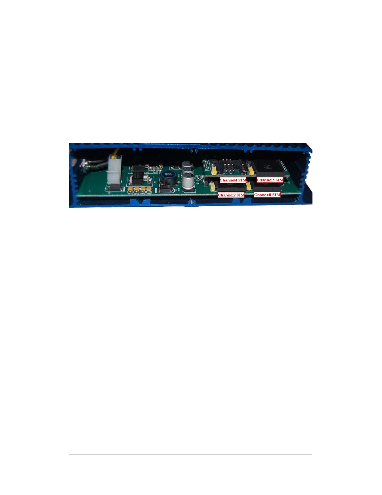
Use Triangular screwdriver to open the six triangular screws at the right
baffle of DK-Em4PS device。Move off the right baffle of it, the corresponding
relationship, between SIM card slot and module channels is shown in Figure
6-1-1:
Figure 6-1-1
When install SIM card, just press the yellow button on the left of each slot,
can pull out the SIM card sets of a corresponding channel, if need SIM card
embedded , insert the card slot once again。
Driver Installation for Module
Let Device connect with a power supply firstly, operate it, and then insert
one end of the USB cable into the Mini-USB port on the left side of the
Mini-USB device, insert the USB A-type port of The USB cable into PC with
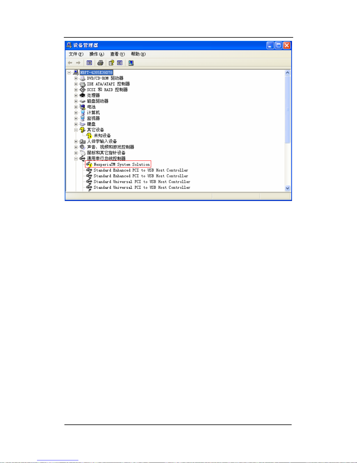
Windows system。After all, Open the Device Manager,Will appear information
of the device shown in Figure 6-2-1。
- 10 -
Page 11
Ningbo Putian Communication Technology Co., Ltd
- 11 -
Figure 6-2-1 Device list before the driver is not installed
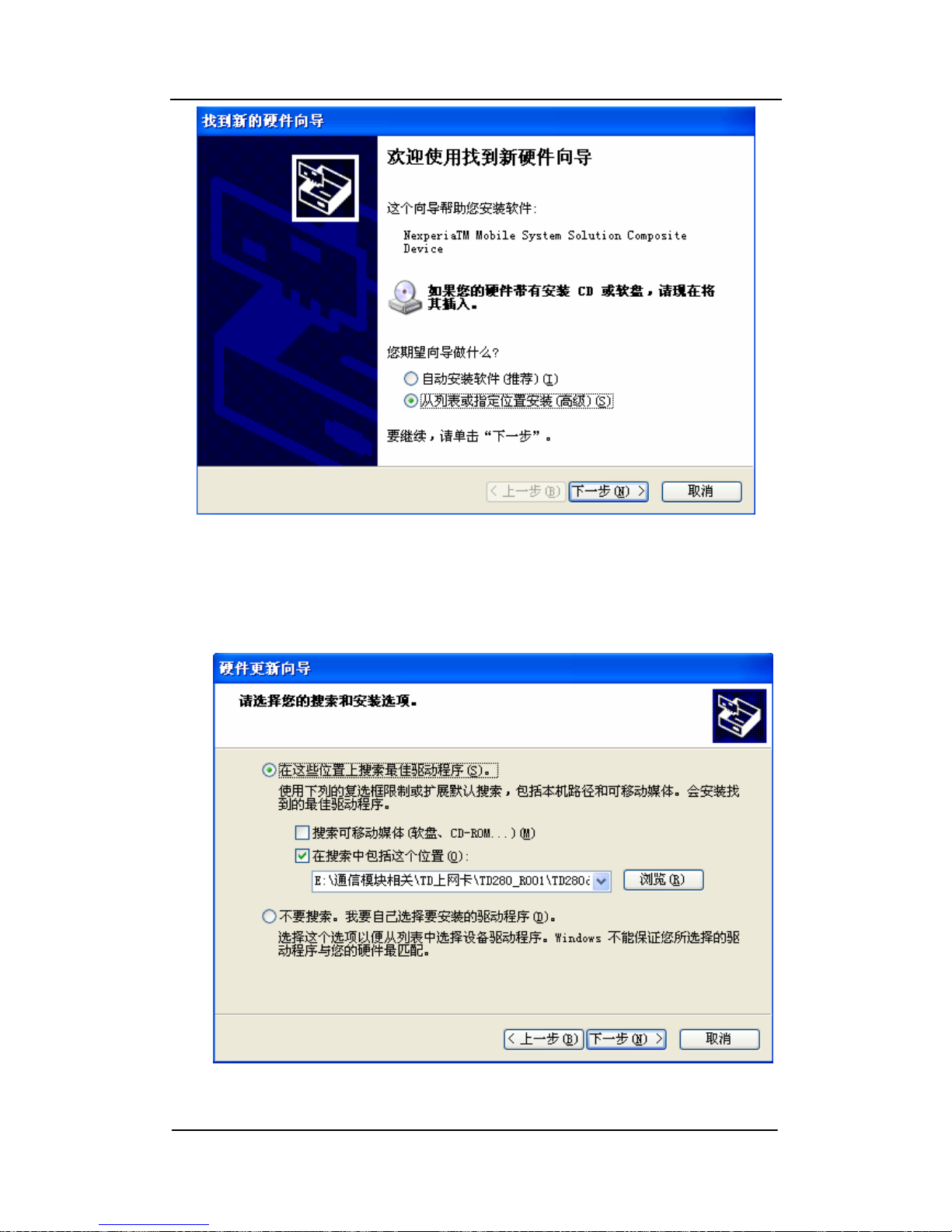
A device connects with a PC at the first time; the system will be prompted
to install a module driver。Will appear a tip to install a module driver in Figure
6-2-2 interface。
Page 12
Ningbo Putian Communication Technology Co., Ltd
Figure 6-2-2 a tip to install a module driver
Select "Installation from a list or a specific location", click next。Browse
and select the directory where a installation files is in, click "OK" button
Figure 6-2-3
- 12 -
Page 13
Ningbo Putian Communication Technology Co., Ltd
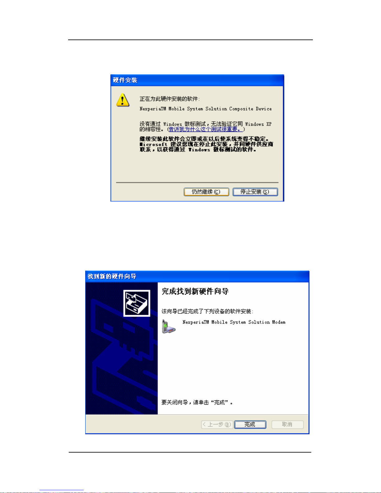
When performing as shown in Figure 6-2-3, click on "Next" to start a drive
installation。
Figure 6-2-4
You will be suggested that drivers did not pass Windows test (Figure 6-2-4)
during the installation process。Select "continue", in the following process to
install drivers, if encounter same suggestion, always select "continue"。
- 13 -
Figure 6-2-5 Device installation is completed
Page 14
Ningbo Putian Communication Technology Co., Ltd
In the driver installation process, you will be repeatedly asked to install
drivers, follow the prompts to install the driver, various drivers for the different
modules, but a basically process of installation is the same。
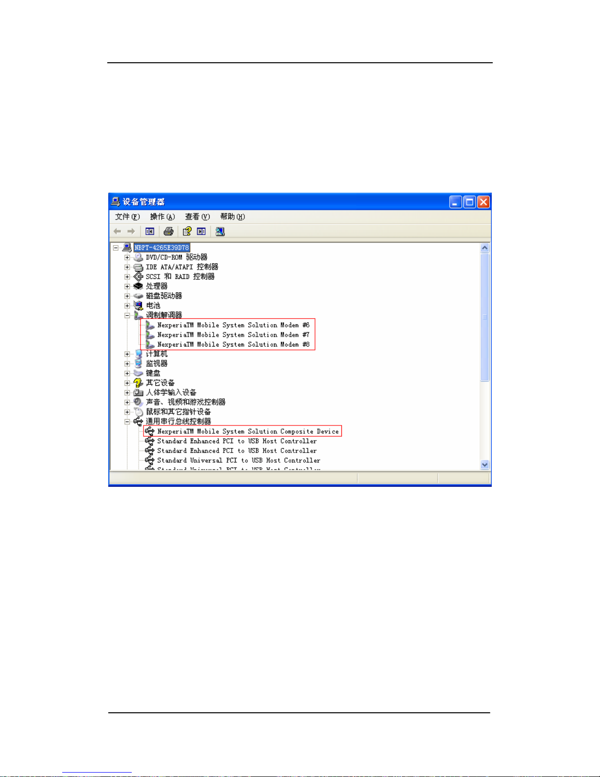
After a successful installation, in the Device Manager, you can see as
shown in Figure 6-2-6。
Figure 6-2-6 interface after driver installation is succeed
6.2. Description for Application program Installation
Note: DK-Em4PS software needs to run Microsoft. NET Framework 2.0 or
later, can not run properly in the version Windows 7 operating system now。
The best platform to run for this software is the PC installed a Microsoft. NET
Framework 2.0 of Window XP system。
- 14 -
Page 15
Ningbo Putian Communication Technology Co., Ltd
Note: originally installed this software before, if need to update a
newer version, you will uninstall the software at first in the Add-Remove
Programs and delete a directory at C: \ Program Files \ nbpt, and then
install the software again。
Double-click at DevicesDemoSetup.msi to begin a installation for
DK-Em4PS Software。
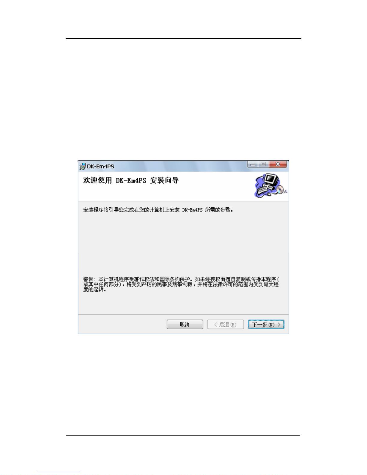
A Setup starts later, will appear a interface as shown in Figure 6-3-1, then
click on Next。
Figure 6-3-1
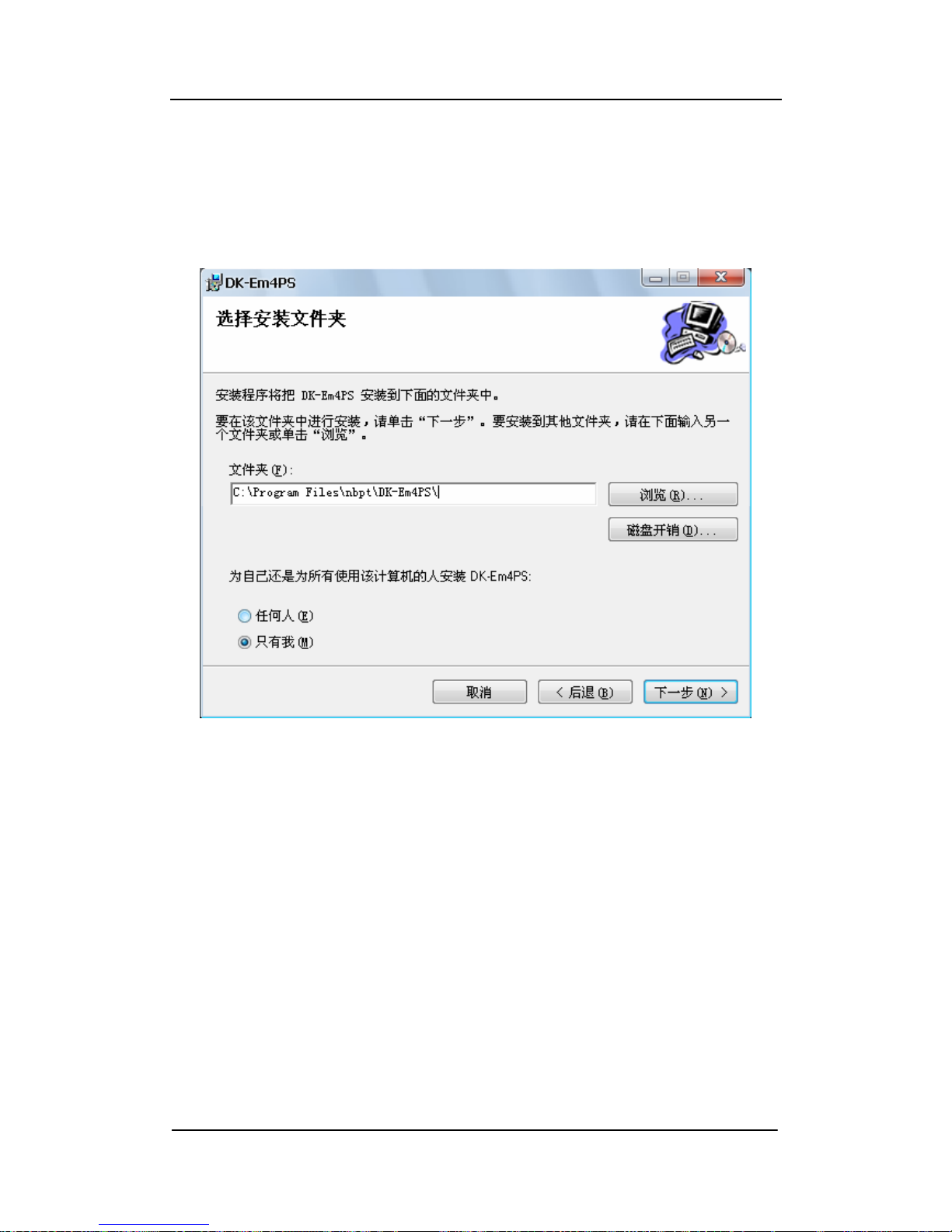
Enter a interface for installation path selection (as shown in Figure 6-3-2),
click on the "Browse" button to choose the installation path, also can click on
the "Next", choose a default installation path to install。
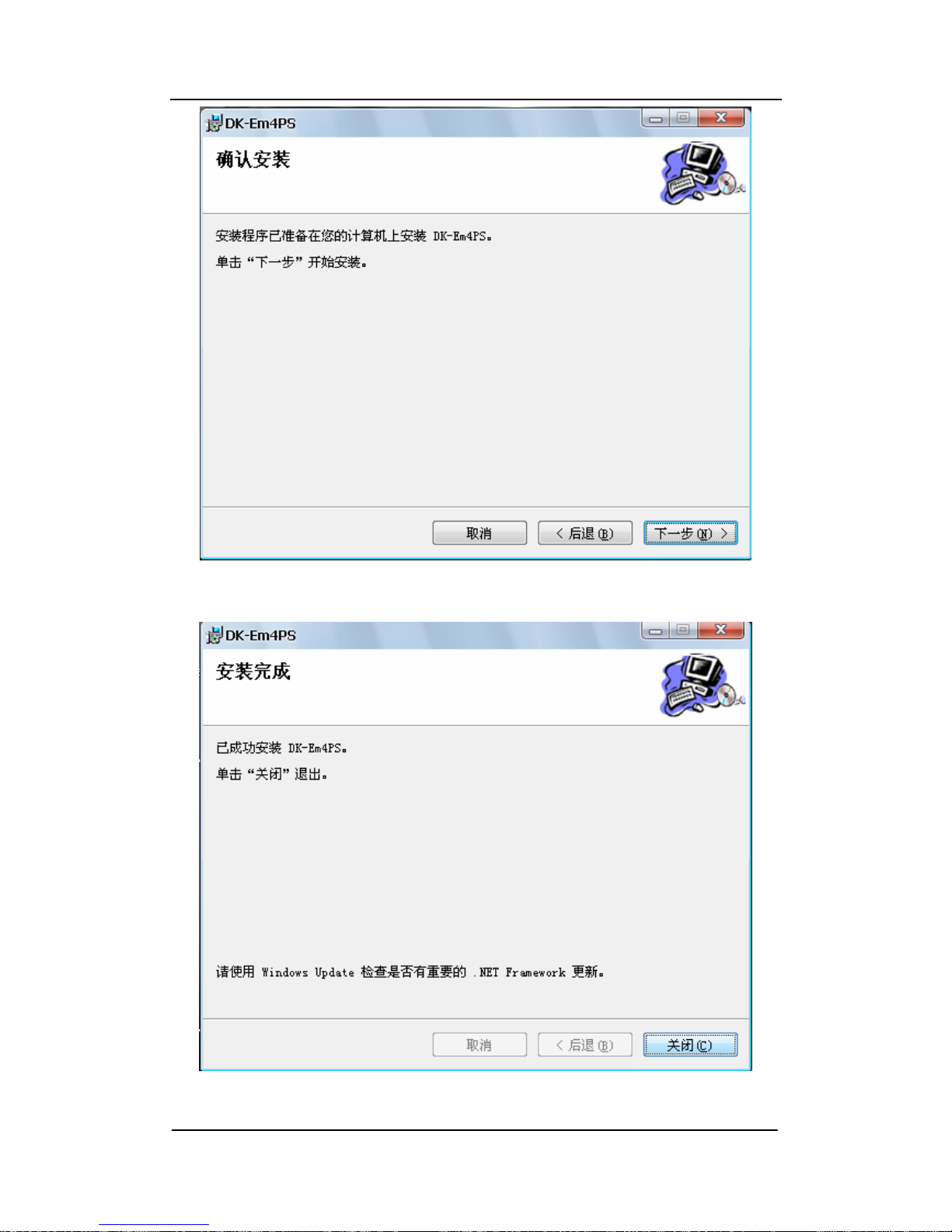
Enter a interface, as shown in Figure 6-3-3, just click "Next" to begin the
installation of a software。
- 15 -
Page 16
Ningbo Putian Communication Technology Co., Ltd
Software installation is successful, enter the interface as shown in Figure
3-4, click "Close" to complete a installation。
Software installation is completed later; a shortcut called "DK-Em4PS"will
be created on the desktop。
Figure 6-3-2
- 16 -
Page 17
Ningbo Putian Communication Technology Co., Ltd
Figure 6-3-3
Figure 6-3-4
- 17 -
Page 18
Ningbo Putian Communication Technology Co., Ltd
6.4. Description for Application program's use
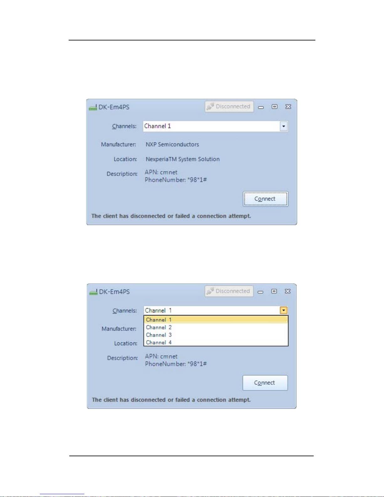
Double-click an icon called "DK-Em4PS" on the desktop to run the program。
Program interface is shown in Figure 6-4-1:
Figure 6-4-1
Click a drop-down menu of "Channels", you can choose the device
channel (as shown in Figure 6-4-2),
Figure 6-4-2
- 18 -
Page 19
Ningbo Putian Communication Technology Co., Ltd
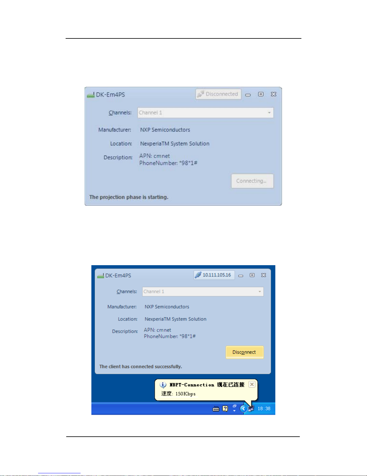
Choose the first channel, and press "Connect" button to start a dial-up of
the GSM network at the first channel。Will appear a dial-up interface as shown
in Figure 4-4-3。
Figure 4-4-3
Dial-up is successful, will appear the interface as shown in Figure 6-4-4,
will also appear networking connected in the right column of a system。
- 19 -
Figure 6-4-5
Page 20

Ningbo Putian Communication Technology Co., Ltd
To disconnect the network connection, simply click the "Disconnect"
button on the Lower right of software, you can disconnect。
6.5. Notes
6.5.1. put SIM card into the SIM card slot firstly, and put it into modem based
on the correspond slot number。
Note: when charge, do not plug SIM card! Otherwise, it may damage
SIM card。
6.5.2. When it’s in use, the procedure or the machine occurs instability, may
try restarting the machine or the PC-end programs.
6.5.3. Attachments:
1.
Antenna 4
2.
SIM Cato 4
3.
Power Line 1
4.
12V power adapter 1
5.
Triangle Screwdriver 1
- 20 -
Page 21

Ningbo Putian Communication Technology Co., Ltd
7、FCC Statement
NOTE 1:
This device complies with Part 15 of the FCC Rules. Operation is subject to
the following two conditions:
(1) This device may not cause harmful interference, and
(2) This device must accept any interference received, including interference
that may cause undesired operation. Note: The manufacturer is not
responsible for ANY interference, for example RADIO or TV interference,
caused by unauthorized modifications to this equipment. Such modifications
could void the user’s authority to operate the equipment.
NOTE 2:
This equipment has been tested and found to comply with the limits for a Class
B digital device, pursuant to part 15 of the FCC Rules.
These limits are designed to provide reasonable protection against harmful
interference in a residential installation. This equipment generates, uses and
can radiate radio frequency energy and, if not installed and used in
accordance with the instructions, may cause harmful interference to radio
communications. However, there is no guarantee that interference will not
occur in a particular installation. If this equipment does cause harmful
interference to radio or television reception, which can be determined by
turning the equipment off and on, the user is encouraged to try to correct the
interference by one or more of the following measures: Reorient or relocate
the receiving antenna. Increase the separation between the equipment
and receiver. Connect the equipment into an outlet on a circuit different from
that to which the receiver is connected. Consult the dealer or an experienced
radio/TV technician for help.
- 21 -
Page 22

Ningbo Putian Communication Technology Co., Ltd
Ningbo Putian Communication Technology Co., Ltd
Fax: 0574-28888989
Email:[email protected]
Phone No for Technical Support: 0574-88051015
- 22 -
 Loading...