

Page 1
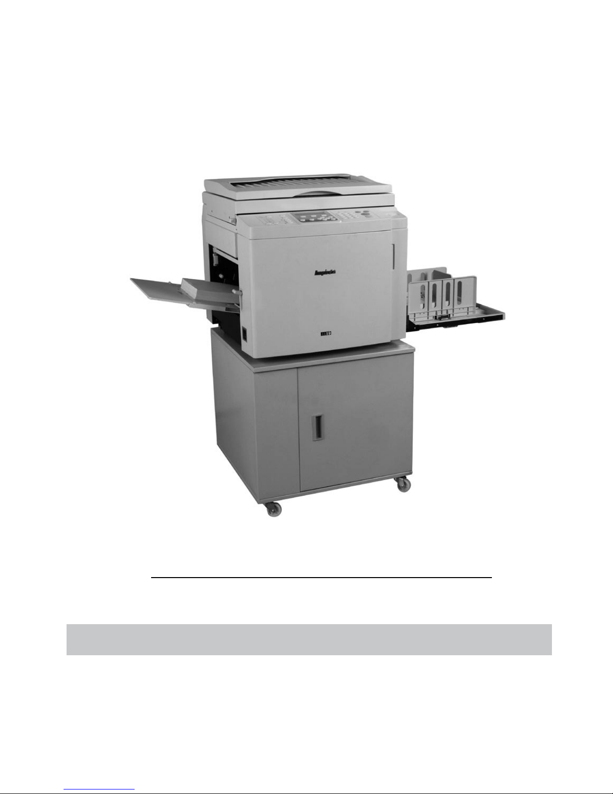
Read all instruction before start-up the machine
MODE L S BPS 101\ 201\ 301
OPRATIN G MAN AUL
BL UE PRIN T SOL UTION S
Please save this instruction manual for later use
Page 2

Page 3

1
ABOUT US
Ningbo R.D.C Office Equipment Co, Ltd was established in 1988. With fast
development, R.D.C has invested and extended the second factory in the new industry
area, Yinzhou Investment and Innovation Center, in 2001.
Ningbo R.D.C Office Equipment Co, Ltd is one of the famous high-tech office
equipment company, producing digital duplicator, stencil duplicator, folding machine,
binding machine, paper shredder, paper cutter and so on. Our company was awarded
“National key high-tech enterprise” by the National Ministry of Science and
Technology.
We insist on “Quality Today, Market Share Tomorrow” as our
guideline
, take “Developing
print technique, promoting national industry” as our task, and successfully developed
series of digital duplicator. Digital duplicator integrates scanning, master making and
printing functions. It is of advanced technologies and high degree of difficulty, filled the
technology blankness in China, and obtained 24 items national patent. These products
obtained series of national honors like “National New Product”, “National Torch Program”,
“National Technology Innovation fund” etc. Currently our digital duplicators have 2
registered brands, “RongDa” and “Caven”, including more than 30 models.
R.D.C has an excellent management team, and strictly carries out ISO9001:2000 on
management and control. Our pr
oducts are not only sold all over China, but also exported
to Japan, Korea, Singapore, Thailand, Malaysia, Brazil, South Africa, Middle East, and
other countries and districts. Fast and excellent after service ensure our customer free from
any possible after-sales trouble. Satisfaction of our customer is our best promise.
Young, brave and sapiential Rongda people would like to strive together with all friends
and promote Chinese printing technology to step forward to the world!
Address:928, ChengXin Road, YinZhou Investment & Innovation Center
Website: www.nbrdc.com
Declaration
1. This product is A-Grade, which may cause radio interference in the environment. In this
case, the user may need to take counter measure against it.
2. Any modification on the specification shall not be notified. Please kindly understand and
coutact the manufacturer if there is any question on this manual.
Page 4

market and technically support the range of products.The Blue range of Duplicators
our range of Duplicators for the past 5 years. They are fully trained and certified to
Ningbo R.D.C Office Equipment Co., Ltd.
For any further information please don’t hesitate to contact the undersigned.
It is an exclusive brand that is only distributed by Bule Print Solutions and their
Distributions Network..
are manufactured by R.D.C. OFFICE EQUIPMENT:
This is to confirm that Blue Solutions International has been a Global Distrobutor of
To whom it may concern.
16 February 2010
th
DISTRIBUTOR CERTIFICATE
Signature:
2
Stamp:
signed by General Manager
Yours Sincerely,
Page 5

———————————————————————————————————
3
Distributor Certificate 2
Declaration ————————————————————————————————————1
Contents
About Us—————————————————————————————————————1
Safety Guides———————————————————————————————————6
Machine Placement—————————————————————————————————9
Machine Cleaning—————————————————————————————————10
Notice on Printing and Printouts———————————————————————————11
Chapter 1. Before Use
Part Name and Functions——————————————————————————————13
Paper Feed Part——————————————————————————————————15
Drum Unit————————————————————————————————————16
Paper Receiving Part————————————————————————————————16
Master Disposal Box Part——————————————————————————————17
Master Making Part————————————————————————————————17
Operation Panel——————————————————————————————————18
Specified Original and Printing Paper—————————————————————————20
The Principles of Master Making and Printing——————————————————————21
Capital 2. Basic Functions of Master Making and Print
Turn on the Power—————————————————————————————————24
Placement of Printing Paper—————————————————————————————25
Open the Paper Receiving Tray———————————————————————————26
Installation of Master————————————————————————————————27
Installation of Ink—————————————————————————————————29
Placement of Original————————————————————————————————30
Choose Paper Size—————————————————————————————————32
Master Making——————————————————————————————————34
Printing—————————————————————————————————————35
Turn off the Power—————————————————————————————————36
Page 6

————————————————————————— ———75
Display Error on LCD and Simple Solution——————————————————————73
Master Making/printing Error———————————————————————————72
No Current———————————————————————————————————71
4
Chapter 3 Printing Operation
Enlargement and Reduction—————————————————————————————38
Automatic Zoom————————————————————————————————39
Free Zoom——————————————————————————————————41
De n s i ty A d j us t i n g ————————————————————————————————42
Scanning Density Adjusting ————————————————————————————42
Master-making Density Adjusting ——————————————————————————43
Printing Densit y Adjusting ——————————————————————————————43
Char/Char&Photo/ Photo Mode———————————————————————————44
Two in one Master Making——————————————————————————————45
Book Mode ————————————————————————————————————47
Chapter 4 Other Functions
Counter Display Function—————————————————————————————50
Printing Speed Adjustment—————————————————————————————51
Printing Position Adjustment ————————————————————————————52
Power Save Function————————————————————————————————53
Confidential Function———————————————————————————————53
Comp uter Print Functio n———————————————————————————————54
The Instruction of Dr iver Installation——————————————————————————55
Chapter 5 Consumables Replacement
Ink Replacement—————————————————————————— ———————63
Mast er Re placement———————————————————————————————65
Taking out Disposal Master————————————————————————————67
Printing Paper Replacement————————————————————————————69
Chapter 6 Trouble Shooting
Placement of Drum———
Page 7

Replace the Soft Screen——————————————————————————————90
Replace /Clean the Printing Roller——————————————————————————89
Replace the Paper Switch——————————————————————————————88
Replace the Friction Pad——————————————————————————————87
Maintenance———————————————————————————————————86
Specifications———————————————————————————————————85
Master Load Error—————————————————————————————————82
Master Ejection Error——————————————————————————————80
Paper Jam———————————————————————————————————77
Paper Empty——————————————————————————————————76
5
Chapter 7 Specifications and Maintenance
Page 8
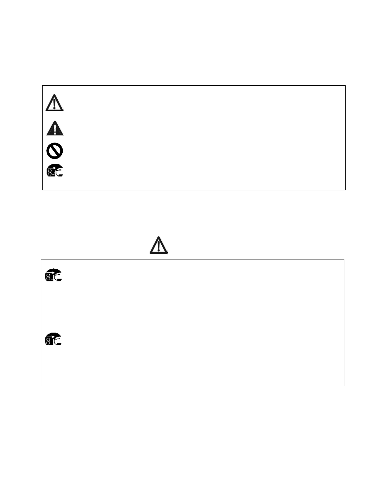
It means forbidden.
machines. These indications are for dangerous
Safety Guides(Please read this section carefully and follow it)
There are different symbols and pictures in this manual, and some labels are also attached on the
warning. The explanation is as below:
Warning
: Very dangerous. It may cause serious harm by incorrect operation.
Attention
: Very dangerous. It may cause hurt by careless operation.
In some case it means a indication while in some case it means forbidden.
●
These are very serious safety guides which should be followed.
Warnings:
When sundries get into inside of the machine, please do not use the machine,
otherwise it may cause fire or electric shock.
●
Please first cut off power and contact the dealer.
Please do not use the machine under unusual condition like high temperature,
smoke, fog or abnormal odor; otherwise it may result in fire and electric shock.
●
Please first cut off power and contact the dealer.
6
Page 9
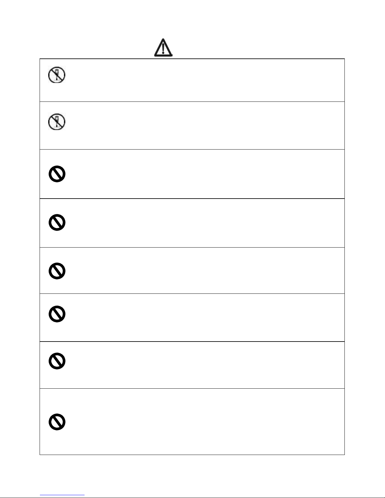
Warnings:
Please do not repair the machine.
●
Or it may cause fire or short circuit.
Please do not teardown the machine optionally.
●
High voltage inside the machine may cause fire or short circuit.
Please do not cut off the power with waterish hand.
●
Or it will cause short circuit.
Please do not mangle, dismantle or pull the power cord.
● Do not put heavy object on the power cord or tied the power cord.
Please do not insert or drop the metal, tinder into the machine.
●
Or it may cause fire or short circuit.
Do not put vase, cup or water container on the machine.
●
Liquid flowing into the machine may cause fire or short circuit.
Do not use power otherwise than specified voltage or connect the machine .
to more than one power source.
● Or it may cause fire or short circuit.
Do not locate the machine in a polluted or dusty place.
●
Or it may cause fire or short circuit.
7
Page 10
Cautions:
Please pull out the power cord before move the machine.
If the power cord is damaged, fire or short circuit may happen.
When take off the power plug, please do not pull the power cord.
●
Or the power cord will be damaged which may cause fire or short circuit.
Please do not place the machine on an unsteady place.
●
In case the machine is overturned, injures may be caused.
Make sure to fix the machine’s feet wheel once locate the machine.
● In case the machine is overturned, injures may be caused.
8
Page 11
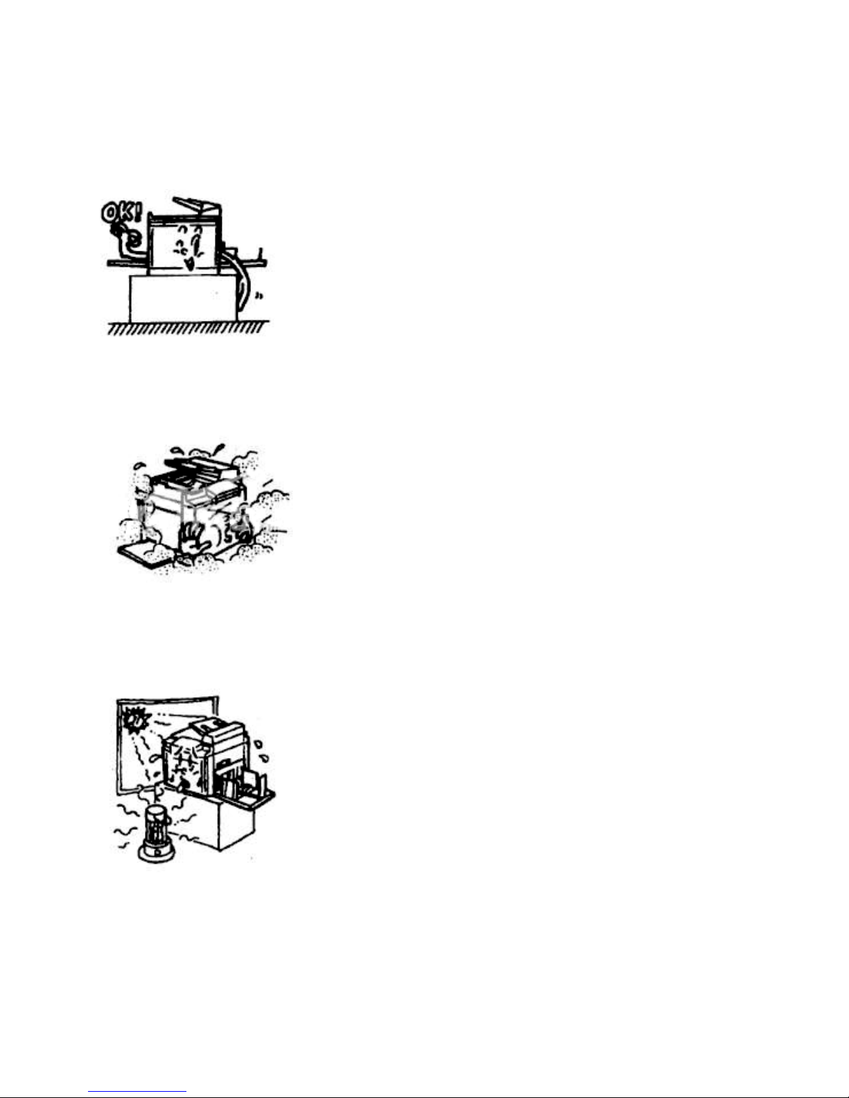
Machine Placement
Put the machine on a level and steady place.
Keep the machine away from dusty place.
Don’t keep machines exposed to direct sun light or
heating equipment like stoves, otherwise the ink will be
metamorphosed, which will result in poor print quality.
Moreover, direct sun light will result in wrong display
of LCD. Also keep the machine away from too cold or
too wet circumstance.
9
Page 12
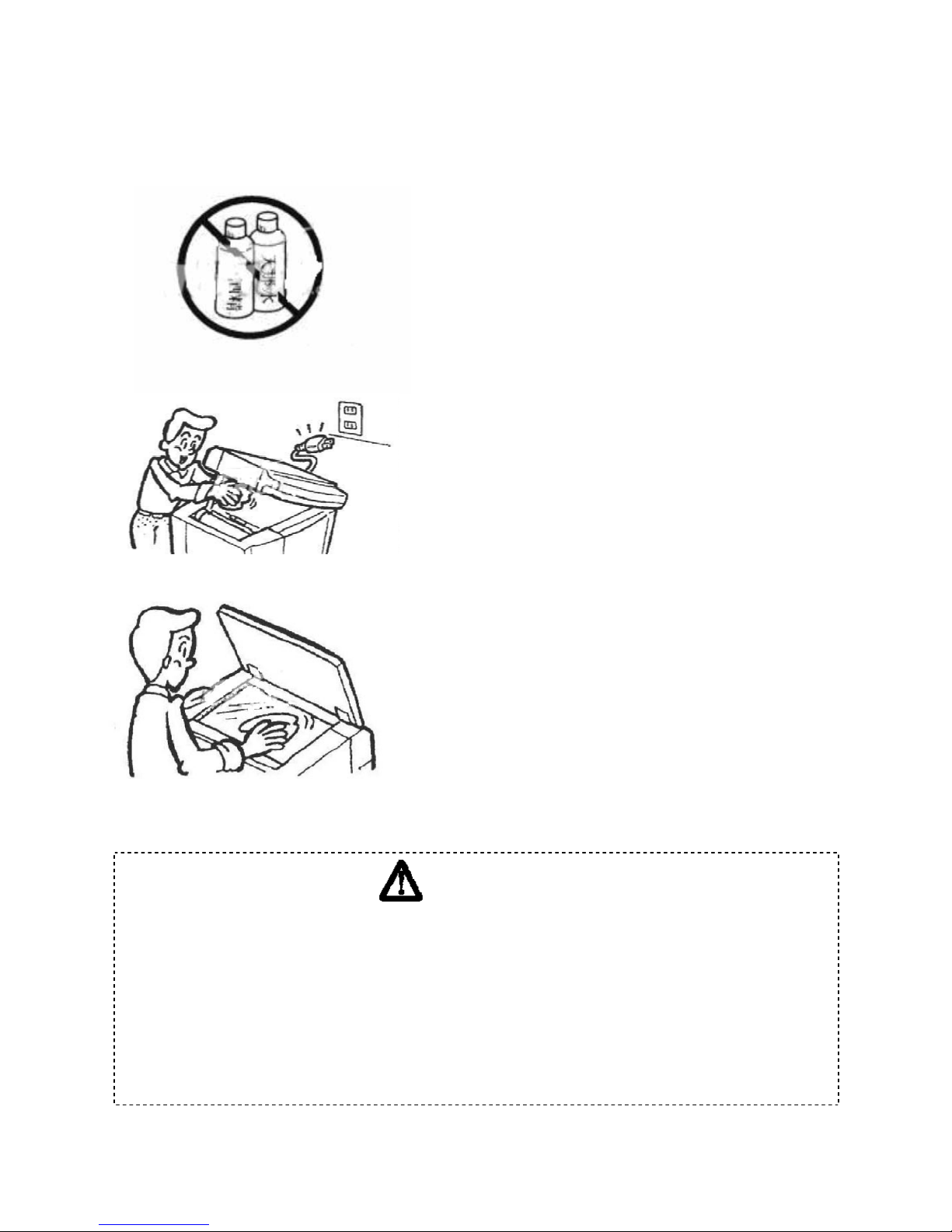
be damaged or its color will be changed.
Machine Cleaning
Please clean the machine according to the
following way. Clean the machine with soft
cloth, water and neutral solvent. The alcohol
and organic solvent are not allowed to clean
machines, otherwise the machine cover shall
The machine needs cleaning at least once a
week. Make sure to cut off the power and take
off the power plug before cleaning.
When cleaning the glass table, please use soft
cloth to wipe off the dust.
Warning
● Make sure to take off the power plugs before clean, or it will cause fire
or short circuit.
● Do not make the water or cleanser flow into the machine, in case this
happens please contact the dealer, otherwise it will cause fire or short of
circuit.
10
Page 13

license, permits, food ticket should be careful to print.
printed according to the number that
Notice on Printing and Printouts
Caution:
There are some restriction on the presswork, please confirm whether the presswork is
legal or not.
1. Forbidden presswork.
Notes, currency, government stock and local government stock are forbidden to
print, even stamped with “Sample”.
Notes, currency and government stock which are valid abroad are forbidden to print.
Unused stamp and post card are forbidden to print without approval by the
government.
Government issued stamp and the tax paper are forbidden to print.
2. All kinds of stock, permits, bills should be
government allowed. Government issued passports, public/private driving
3. Original with printing droit.
The personal collection and the related unsaleables like books, music book, artwork,
pictures, maps, and photos are not allowed to print.
11
Page 14

12
Chapter 1
Before Use
This chapter provides the basic information about the machines, including
the names of parts, all buttons of control panels, requirement of originals
and print paper.
Part Name and Functions———————————————————13
Paper Feed Part———————————————————————15
Drum Unit—————————————————————————16
Paper Receiving Part—————————————————————16
Disposal Master Box Part———————————————————17
Master Making Part——————————————————————17
Operation Panel
———————————————————————18
Specified Original and Print Paper————————————————
20
z
Specified Original
—————————————————————20
z
Specified Print Paper
————————————————————21
The Principles of Master Making and Printing———————————21
z
Master Making
—————————————————————21
z
Printing
————————————————————————22
Page 15
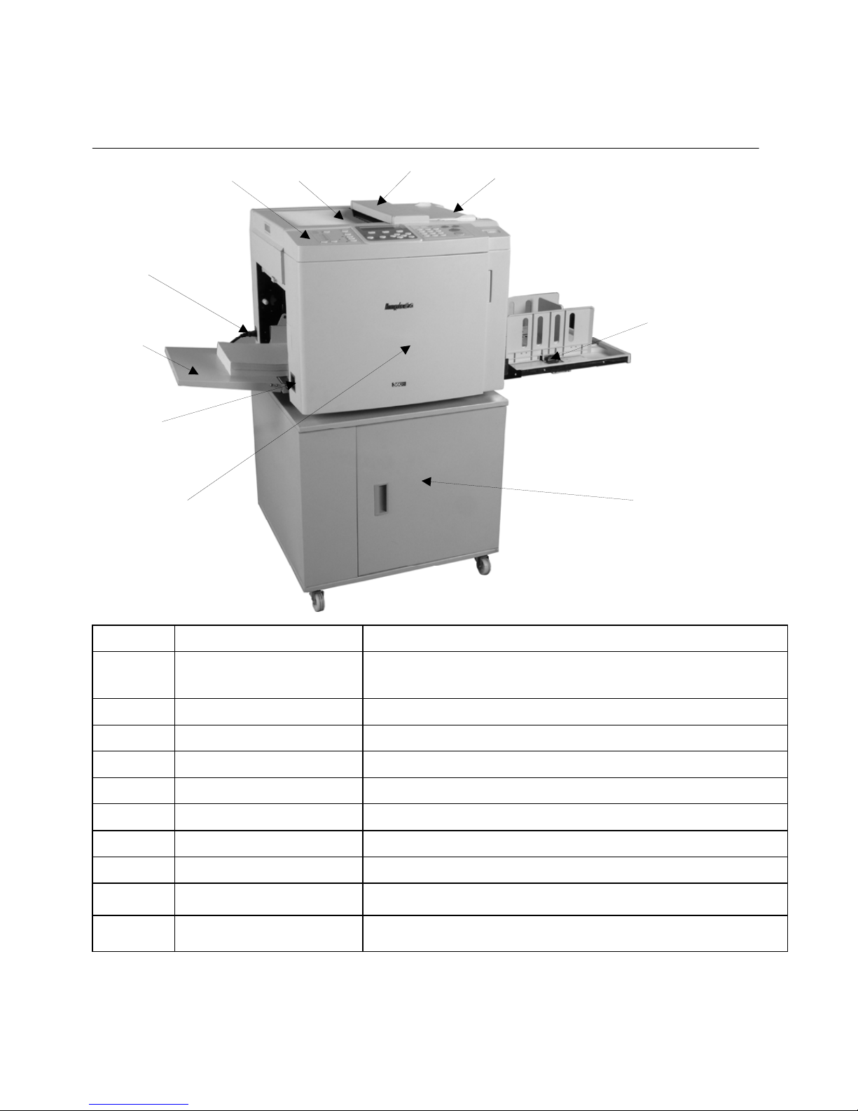
Machine appearance (BPS 101)
Part Name and Functions
4
13
Item Part Functions.
1 Control panel Displays the machine information, and control
machine’s working process.
2 Original receiving tray Delivers and receives the original.
3 Scan cover Original scan.
4 Original guiding tray Feeds and locates the original.
5 Paper receiving tray Receives and loads the printouts.
6 Stand (optional) Machine location.
7 Front door Open the door to replace drum and install ink.
8 Power supply switch Turn on/off power.
9 Paper feed tray Paper loading.
10 Power cord Connect the power.
1 2
10
9
8 7 6
Page 16
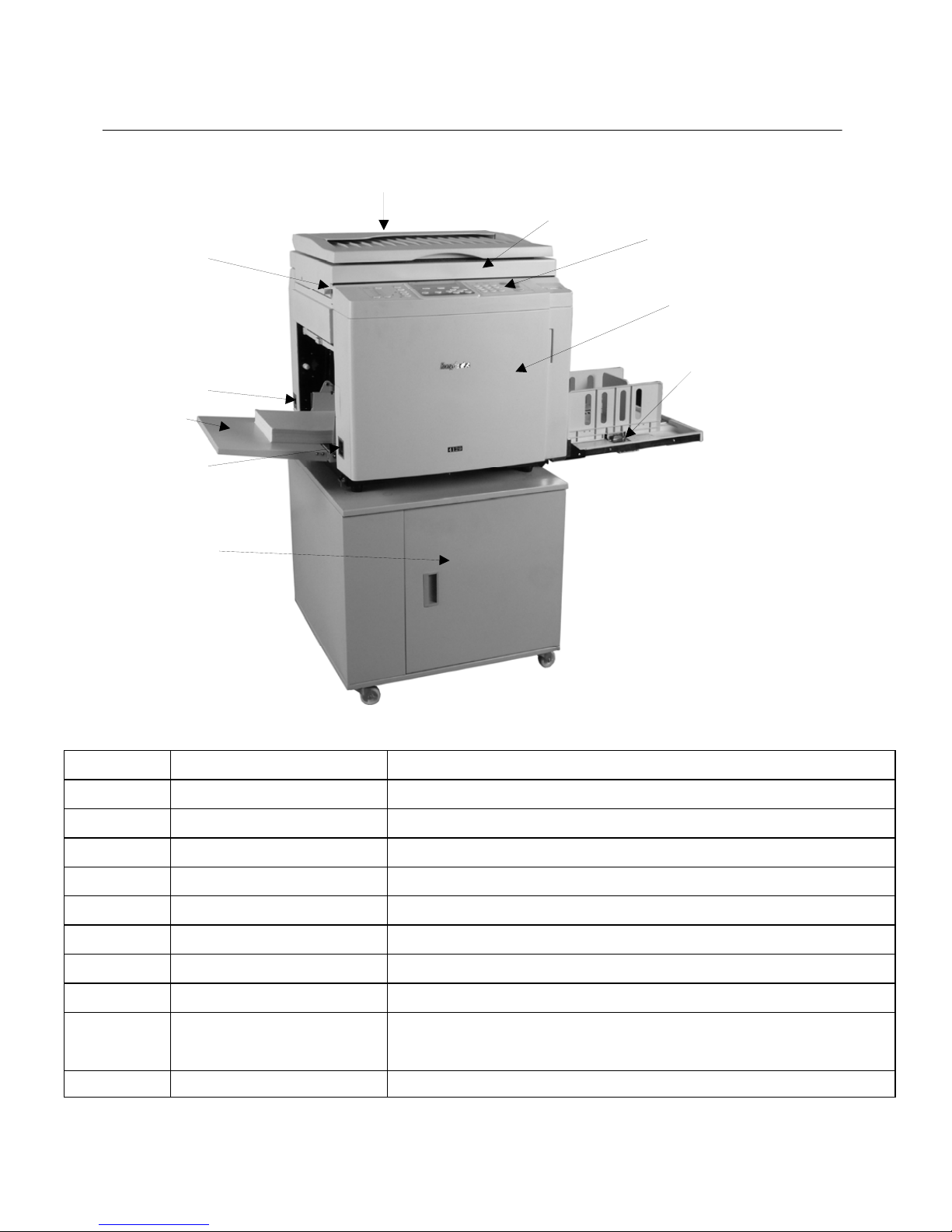
Machine appearance (BPS 201)
1
10
9
2
8
7
3
4
5
6
14
Item Part Functions.
1 Top cover Keeps good contact between the original and the scan glass.
2 Scan flat lock level Locks up the scan part.
3 Power supply socket Connect the power.
4 Paper feed tray Paper loading.
5 Power supply switch Turn on/off power.
6 Stand (optional) Machine location.
7 Paper receiving tray Receives and loads the paper.
8 Front door Open the door to replace drum and install ink.
9 Control panel Displays the machine information and control working
p
rocess master plate and print.
10 Scan glass Locates and scans the original.
Page 17
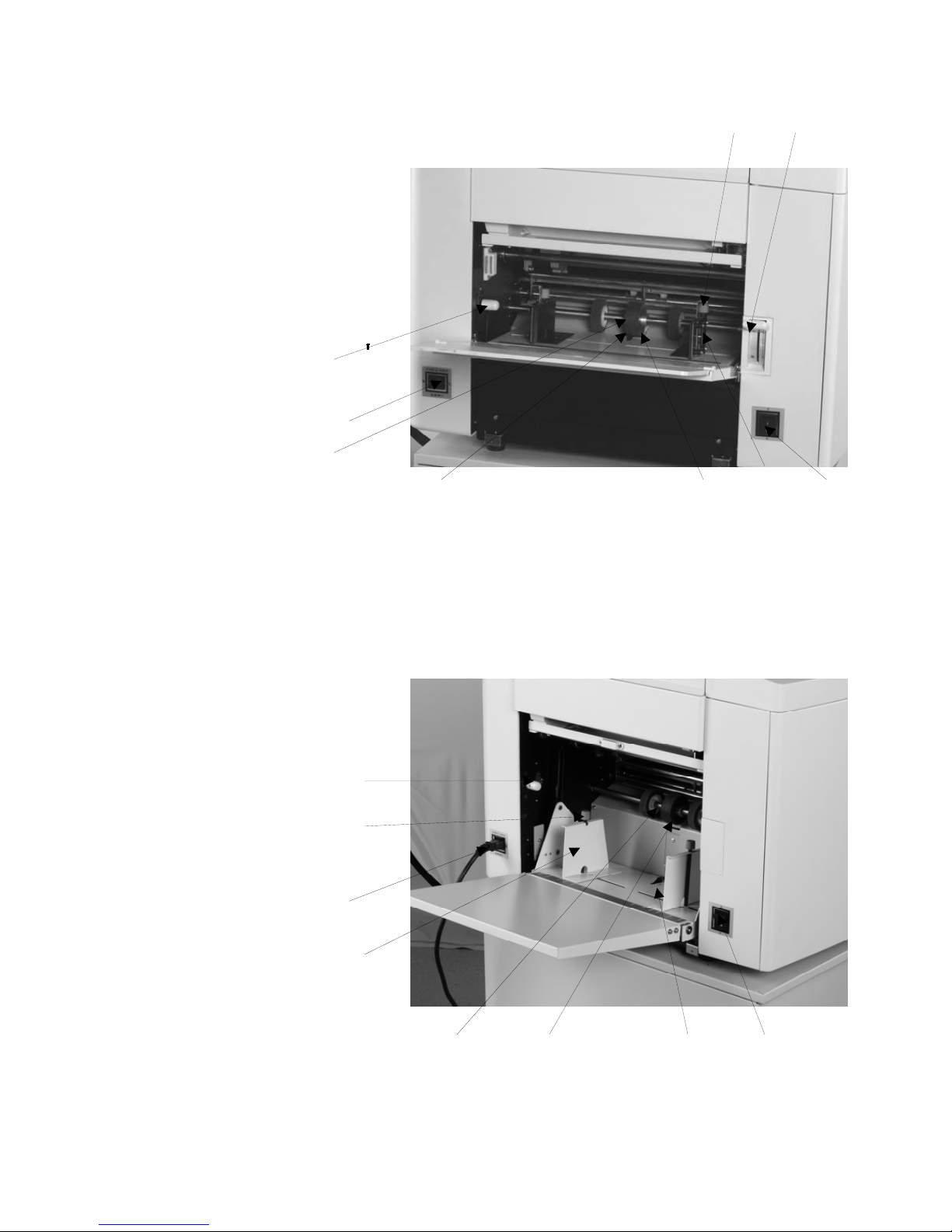
Paper Feed Part (BPS 101/BPS 201)
Paper Feed Part (BPS 101/BPS 201) Ⅰ
9 8
1、Paper feed pressure knob
15
2、Power supply socket
3、Paper feed roller
4、Paper detecting switch
5、Friction pad
6、Paper guide
7、Power supply socket
8、Feed tray lock lever
9、Paper guide adjusting knob
10、Paper feed pressure knob
11、Paper guide adjusting knob
12、Power supply socket
13、Paper guide
14、Paper feed roller
15、Friction pad
16、Paper detecting switch
17、Power supply switch
1
2
3
4
5 6
7
10
11
12
13
14
17
15 16
Page 18
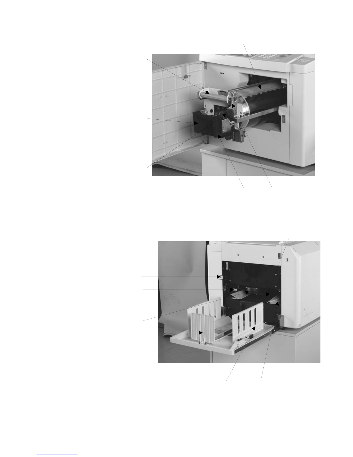
22
Ⅱ Drum Unit
16
18、Drum spanner
18
19、Ink bracket
20、Ink case switch
21、Drum lock switch
22、Drum
23、Ink chip device (optional)
Ⅲ
Paper Receiving Part
24、Disposal master box switch
25、Printing pressure adjusting lever
26、Blower
27、Central guide
28、Paper receiving guide
29、Paper guide plate
30、Paper transport belt
19
20
23 21
30
24
25
27
28 29
26
Page 19
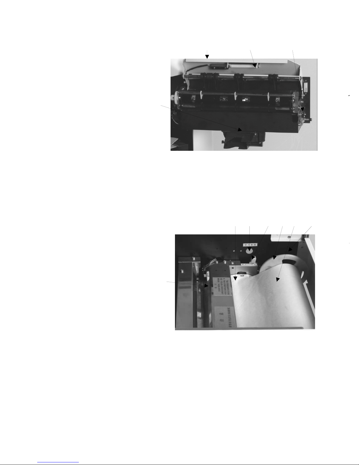
Ⅳ Master Disposal Box Part
32 33
31
31、Disposal master box cover
17
32、Cover switch
33、Disposal master full switch
34、Blower mouth
34
Ⅴ Master Making Part
35、Master guide board
36、Cutter switch
37、Thermal head release lever
38、Master core bracket
39、Master
40、Cutter
41、Master chip device (optional)
35
36 37 38 39 41
40
Page 20
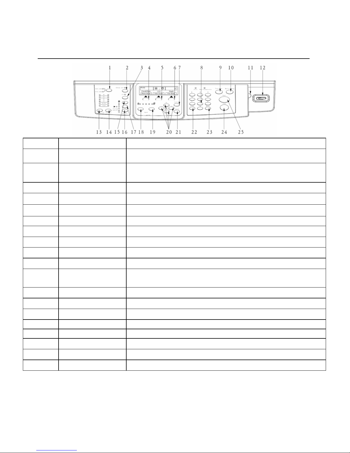
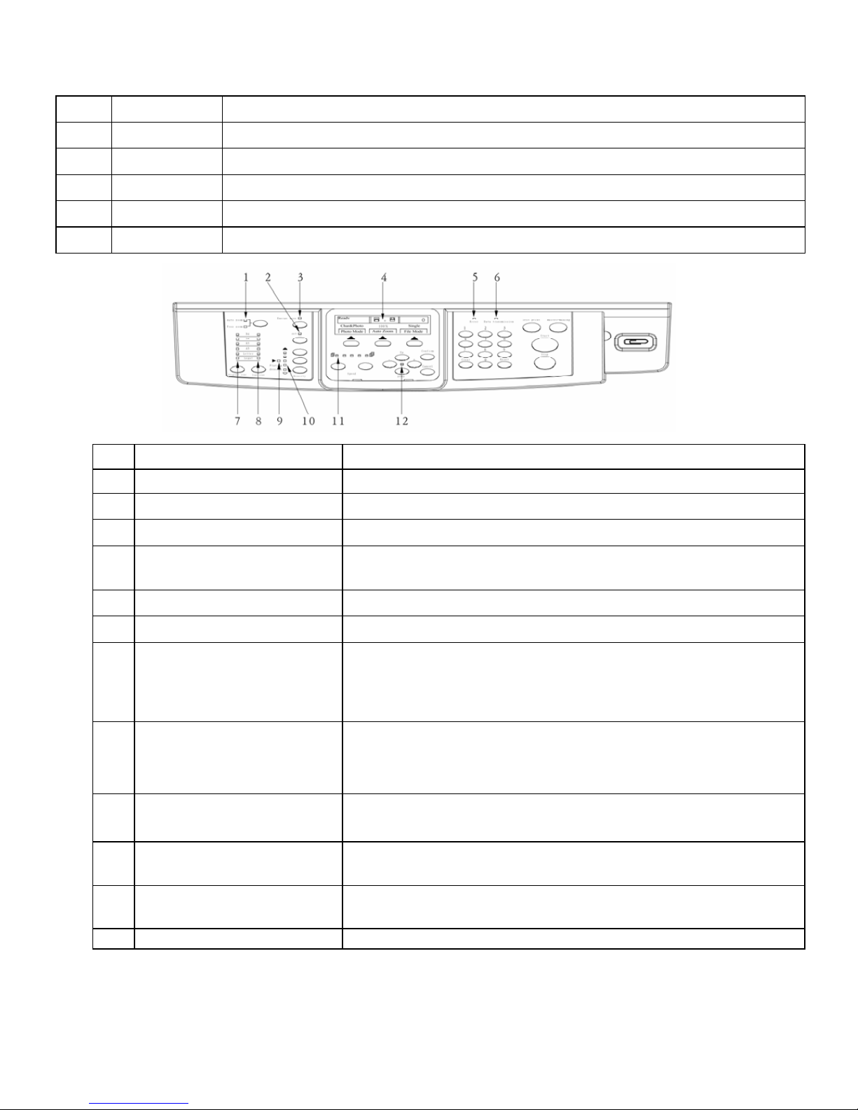
umber Key
Operation Panel
18
Item
N
ame Function.
1 Zoom rate key To switch between automatic zoom mode and manual free zoom mode.
2 Power save key After 1 minute of pressing the key, the machine enter power save mode,
then exit by pressing any key.
3 Set key To enter password set interface.
4 Photo mode key Press it to enter photo mode interface.
5 Auto zoom key Press it to enter zooming rate interface.
6 File mode key Press it to enter file mode interface.
7 Confirm key Confirm the selected item or the set parameters.
8
N
Press it to input the printing number.
9 Test print key Print one sheet of test printout, and main display is effective.
10 Master making key Print it to start master making.
11 LCD screen brightness
ad
j
ust key
Adjust the backlight brightness of LCD.
12 Paper clip’s location Temporary location for paper clips used on the original.
13 Original size key Press it to select original size.
14 Copy size key Press it to adjust copy size.
15 Density key Press it to adjust density of scan or master plate,increase the density.
16 Density key Press it to adjust density of scan or master plate,reduce the density.
17 Density convert key Press to convert between scan density and master plate density.
18 Print Speed key L Press it to reduce print speed.
19 Print Speed key R Press it to increase print speed.
Page 21
Cancel or reset the number of printing paper.
five models sizes for BPS 201:
six sizes for BPS 201:
To indicate printout size, six models sizes for BPS 101 : B4
To indicate original size, six models sizes for BPS 101 : B4
19
20 Cursor keys Change selections in the Main Display. They function when the light is on.
21 Cancel key Cancel current settings, and back to the main interface.
22 * key
23 # key
Press it to return all settings to initial status.
24 Stop key
Press it to stop print.
25 Start key
Press it to start print. The print number is not zero and the Main display is effective.
NO. Key press Functions
1 Zoom indicator light Indicates zoom rate including automatic rate and manual adjusting rate.
2 Setting indicator light Displays code setting state.
3 Energy saving indicator light Energy saving state.
4 LCD main screen Machine state, print sheet number, machine setting, error information,
etc.
5 Err indicator light To indicate error on the machine.
6 Data transfer indicator light To indicate the state of master making.
7
Original size indicator light
,
A4,B5,A5,Legal, Letter;
A3、 B4,A4,B5,A5,Letter.
8
Printout size indicator light
,
A4,B5,A5,Lagal, Letter, automatic zoom rate available;
B4,A4,B5,A5,Lette
r
,automatic zoom rate available.
9 Density conversion indicato
r
light
To indicate scanning density mode or master making density mode,
light on for master making density, light off for scanning density.
10 Density indicator light To indicate scan density or master making density, five grades.
11 Print speed indicator light To indicate print speed, five levels, 55ppm, 70ppm, 85ppm, 105ppm,
120ppm.
12 Cursor keys indicator light When this light is on, the Cursor keys are functioned.
Page 22

BPS 201
BPS 101
◆Notes:
1. It is not allowed to press two or more keys synchronously except the special instructions.
2. At least 1 second interval should be allowed when press two keys continuously.
Specified Original/Print Paper
Specified Original
(
)
● Document feed mode
● Size: Max257mm×364mm
(
)
● Book top mode
● Weight: original paper or book not more than 10 kgs
● Size: Max297mm×420mm
Notes:
Following types of original can not be used:
● The original with crack or file-binding holes.
● The original which has been folded or violently curled.
● The original with staples or paper clips.
● Carbon-backed documents.
● Adhesive paper.
● High transparent original.
20
Page 23
BPS 101/201
BPS 101
Specified Print Paper
Paper sheet 40g/㎡ - 210g/㎡
Paper size Max.297mm×420mm Min.100mm×50mm
Loading capacity
Paper feed tray 950 sheets(70g/㎡)(
)
Paper receive tray 1000sheets(70g/㎡)
21
Cautions
The following types of paper can not be used:
● The paper with crack or file-binding holes.
● The paper with clips or marked folds.
● The paper which was violently curled.
● Carbon-backed paper.
● Adhesive paper.
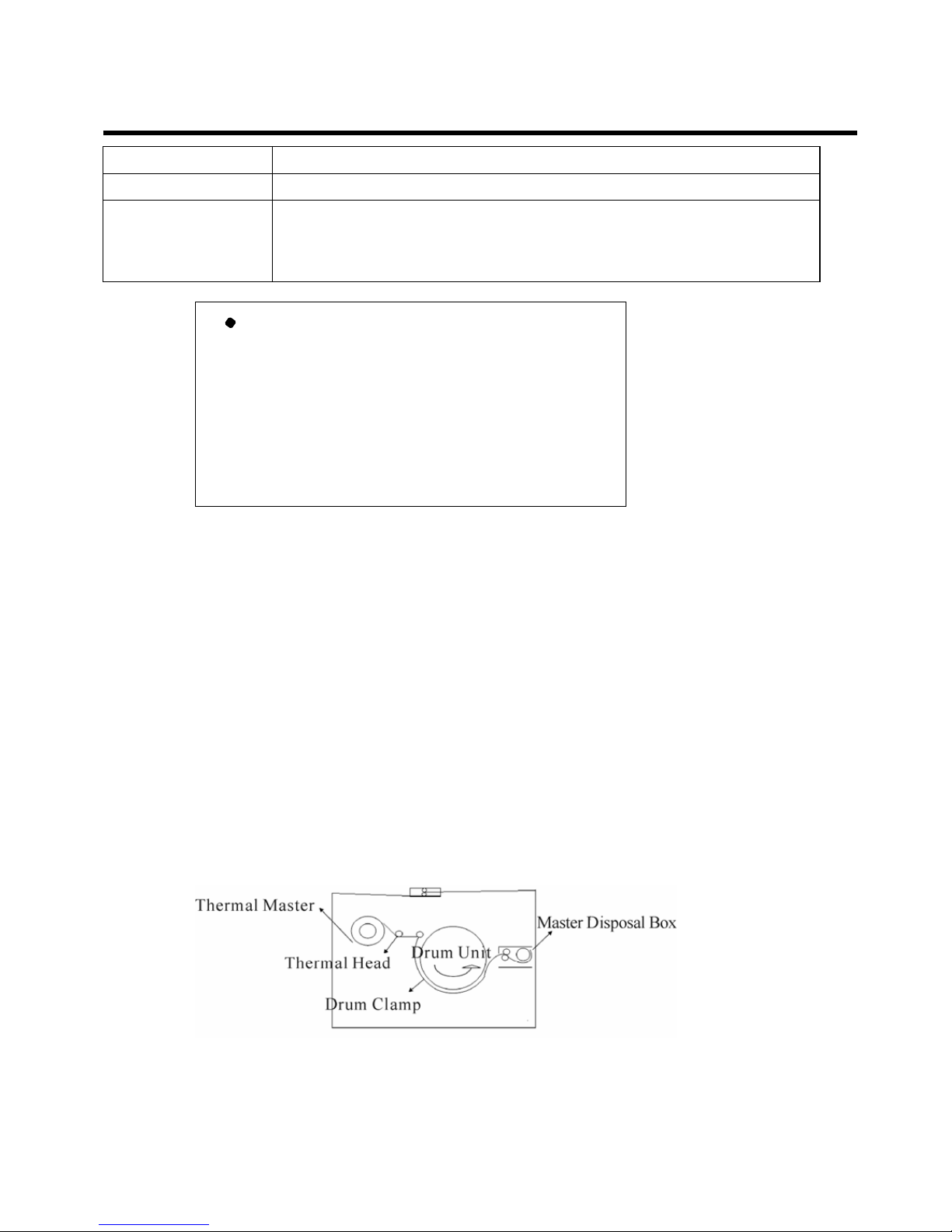
The Principles of Master Making and Printing
Master Making
First of all, the disposal master box collects the printed master and detectives the master collection.
Meanwhile the scanner head reads the image data from the original and transfer the data to the thermal
head. The thermal head prints the image data to the master, and the thermal master is loaded onto the
drum by mechanical part and then the test print is made.
Page 24
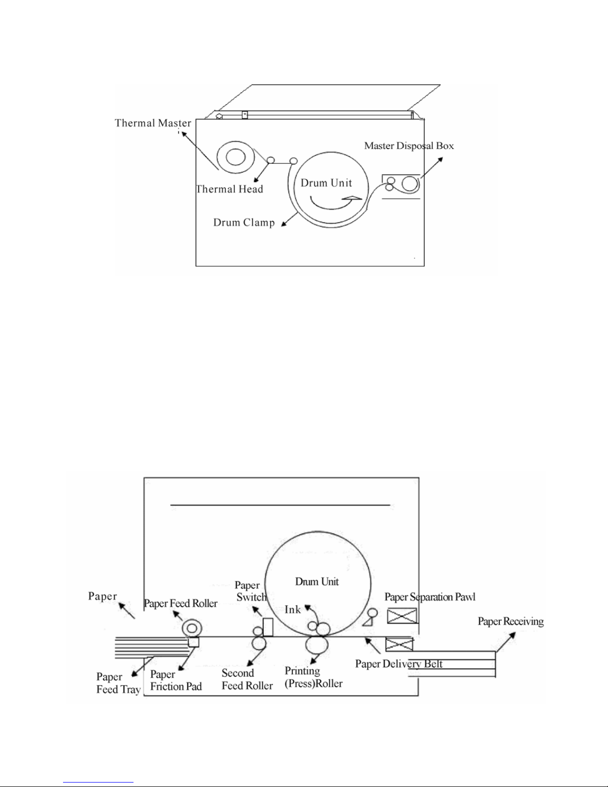
print paper is delivered to the paper receiving tray.
BPS 201
Printing
The paper feed tray will support the paper up, and the paper is separated and delivered to the
second feed roller by cooperation work of paper feed roller and the paper separator pad. Then the paper
is delivered to the clearance between drum and pressure roller. After ink distribution procedures, the ink
is seeped from the tiny mesh of the thermal master on the drum, and through pressing by the pressure
roller to the paper and to the drum, the printing procedure is completed. Shortly the paper is separated
from the master by the blower device, and then by paper separate pawl and the paper transport belt the
22
Page 25

Chapter 2
Basic Functions of Master Making and Print
This chapter states basic procedure of master making and printing in
standard mode.
1. Turn on the Power ————————————————————24
2. Placement of Printing Paper—————————————————25
3. Open the Paper Receiving Tray————————————————26
4. Installation of Master————————————————————27
5. Installation of Ink—————————————————————29
6. Placement of Original———————————————————30
7. Choose Paper Size—————————————————————32
8. Master Making——————————————————————34
9. Printing—————————————————————————35
10. Turn off the Power————————————————————36
23
Page 26
Basic Functions of Master Making and Print
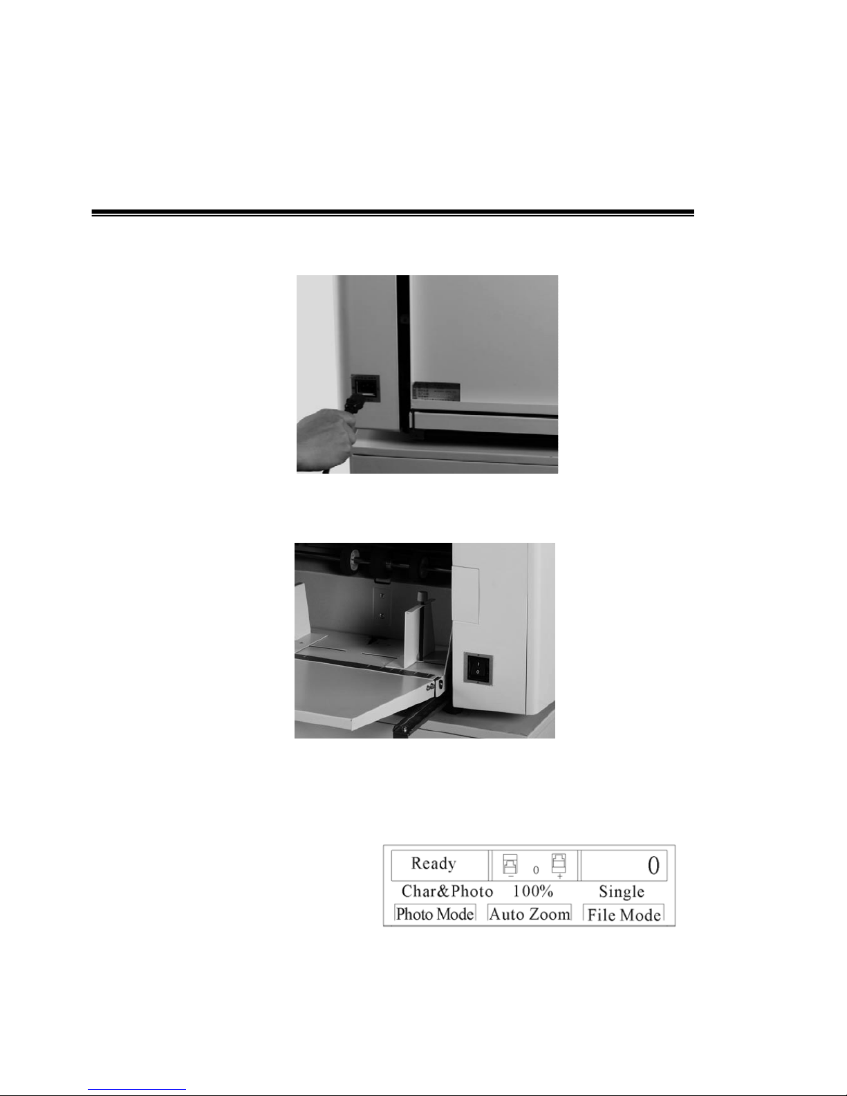
1. Turn on the Power
1. Connect power cord;
2. Turn the power switch to“Ⅰ”position;
24
LCD screen displays “ Ready”, and the machine stays in standard mode:
The settings of standard mode is as listed below.
· Printing number :0
· Zoom rate :100%
· Photo mode :Char&Photo
· P Position :0mm
· Paper Size :B4
· File mode :Single
· Density :Middle
· Speed :Middle
Page 27
The load capacity of BPS 101/201 is 950 sheets ( 70g/
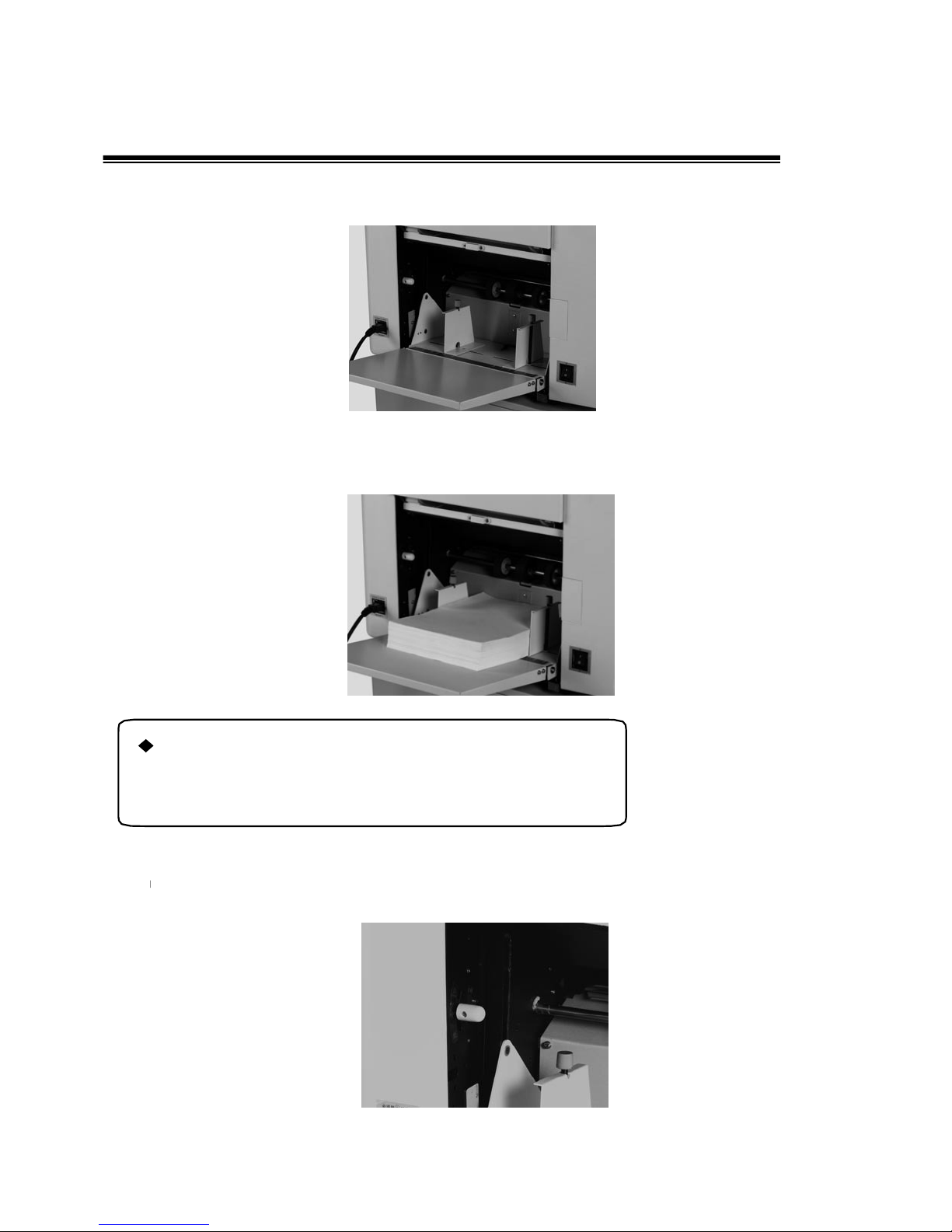
2. Placement of Printing Paper
1.Open the paper feed tray;
25
2.Place the paper sheets, and locate the paper guide;
Notes:
㎡
)
3. Set feed pressure according to the thickness of paper sheets.
Page 28
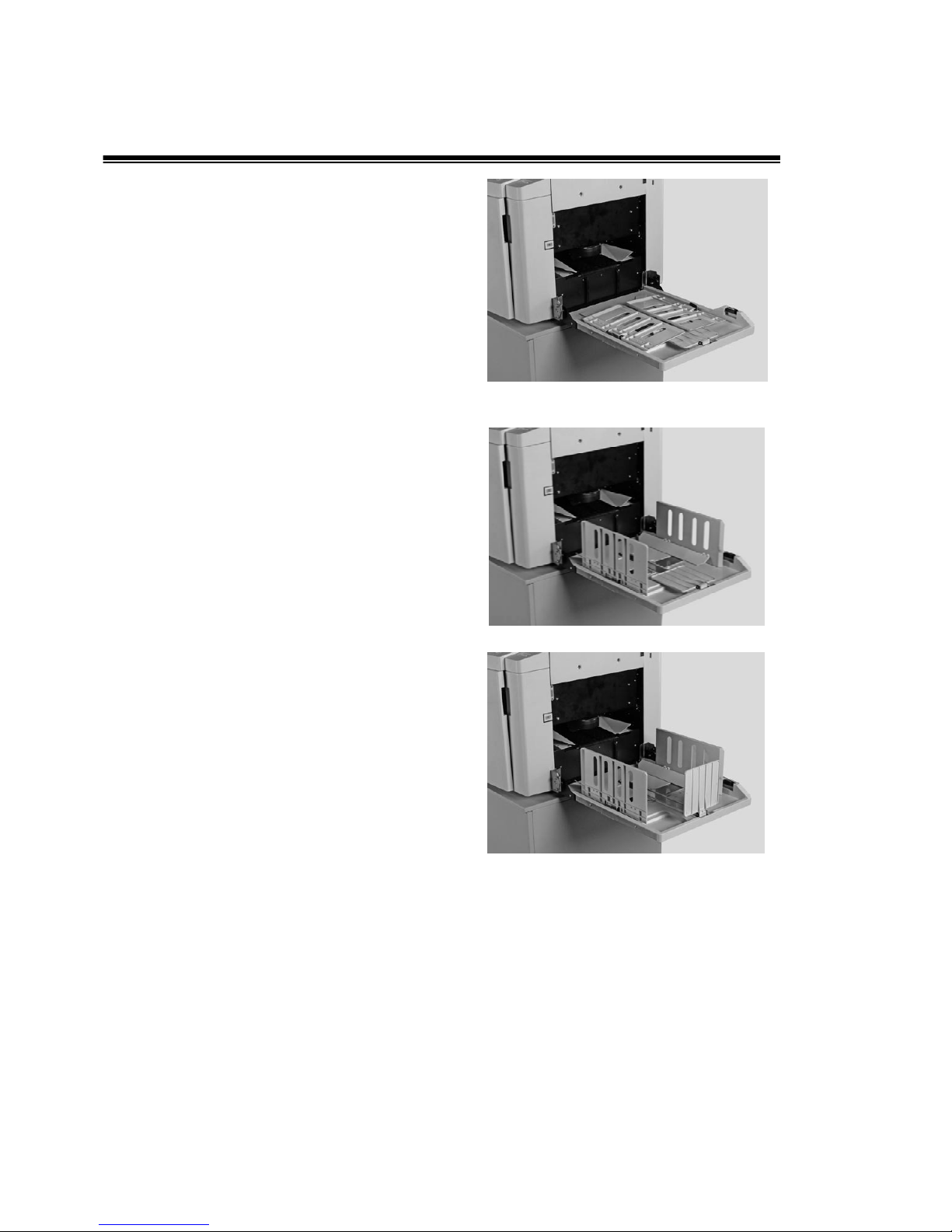
3. Open the Paper Receiving Tray
1. Open the paper receiving tray;
2. Open the paper receiving guide;
3. Open the central gui de;
26
Page 29
)
BPS 201
BPS 101
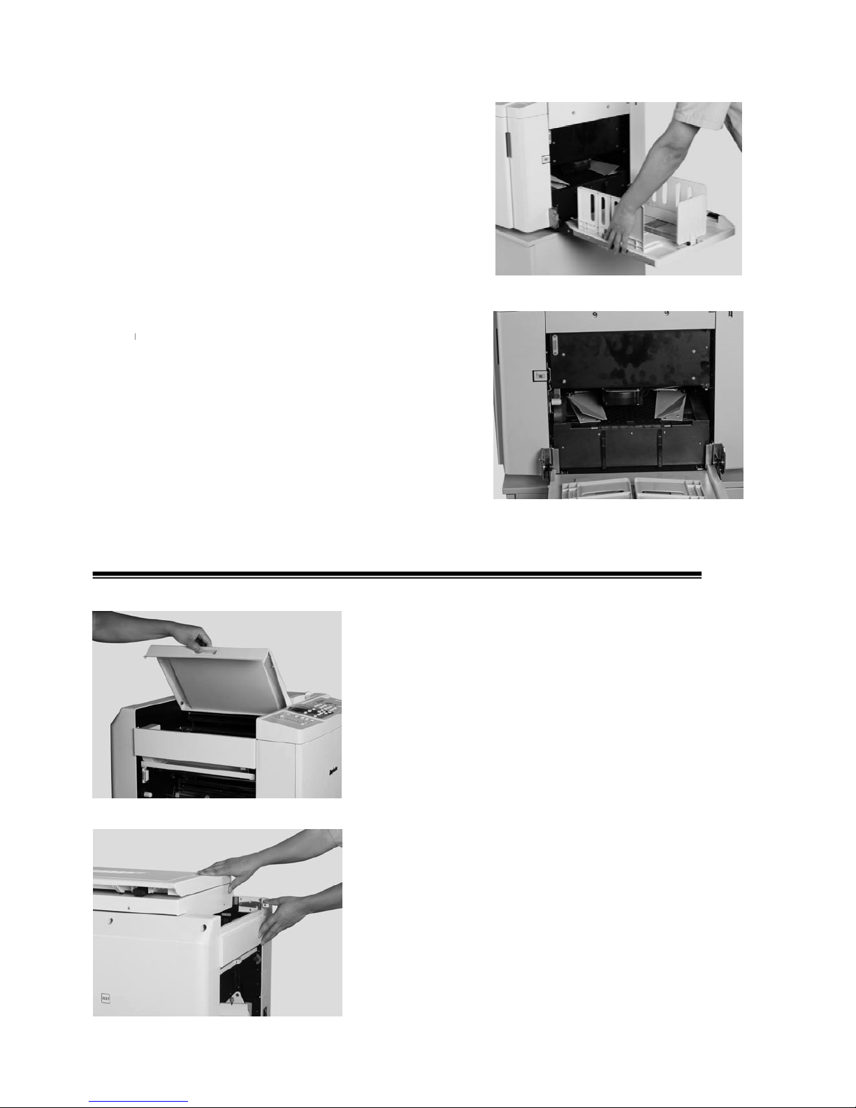
4. Adjust the paper receiving guide and central guide
according to the paper size;
5. Adjust the paper guide plate according to the print
image size.
4. Installation of Master
1. Open the original receive tray (
)
;
Press the scan lock lever, and push the scan flat(
27
Page 30
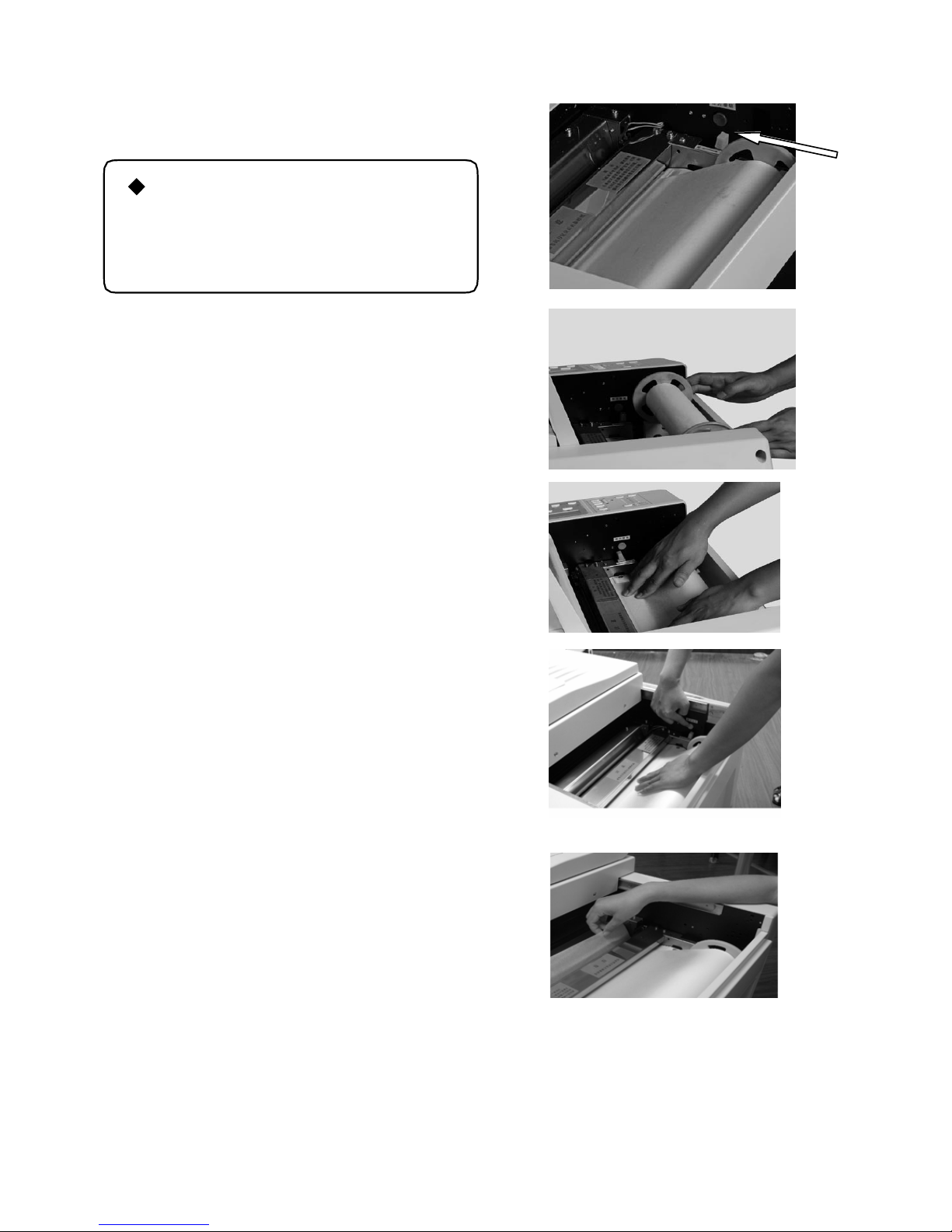
and cut the extra master.
10mm to the cutter blade, pull the master straight, and
“Open” position, put the master head between the print
the print roller and thermal head, keep pressing the cutter
2. Press down the thermal head release lever to “Open”
position;
Notes
Do not touch the thermal h ead,,
otherwise it shall be scraped, which
shall effect master making quality.
3. Put the new master roll onto the master bracket;
4. Three ways of installation:
WayⅠ Feed the master head (with mill finish adown)
between the printing roller and the thermal head, and push
the release lever to position “Close”. Close the scan table
and then master making can be started.
Way Put the thermal head release lever to Ⅱ “Close”
position, master mill finish adown, put the master under
micro switch, the master feed forward automatically, when
the distance is 5-10mm to the cutter, then use right hand to
press thermal head release lever, with left hand pull the
master to the feed entrance, close the scan table and then
master making can be started.
Way Ⅲ Put the thermal head release lever onto the
roller and the thermal head, feed the master forward until
release the thermal he ad release lever to “Close” position.
Press the cutter micro switch
Take out the cut master piece. Close the scan table and then
master making can be started.
28
Page 31
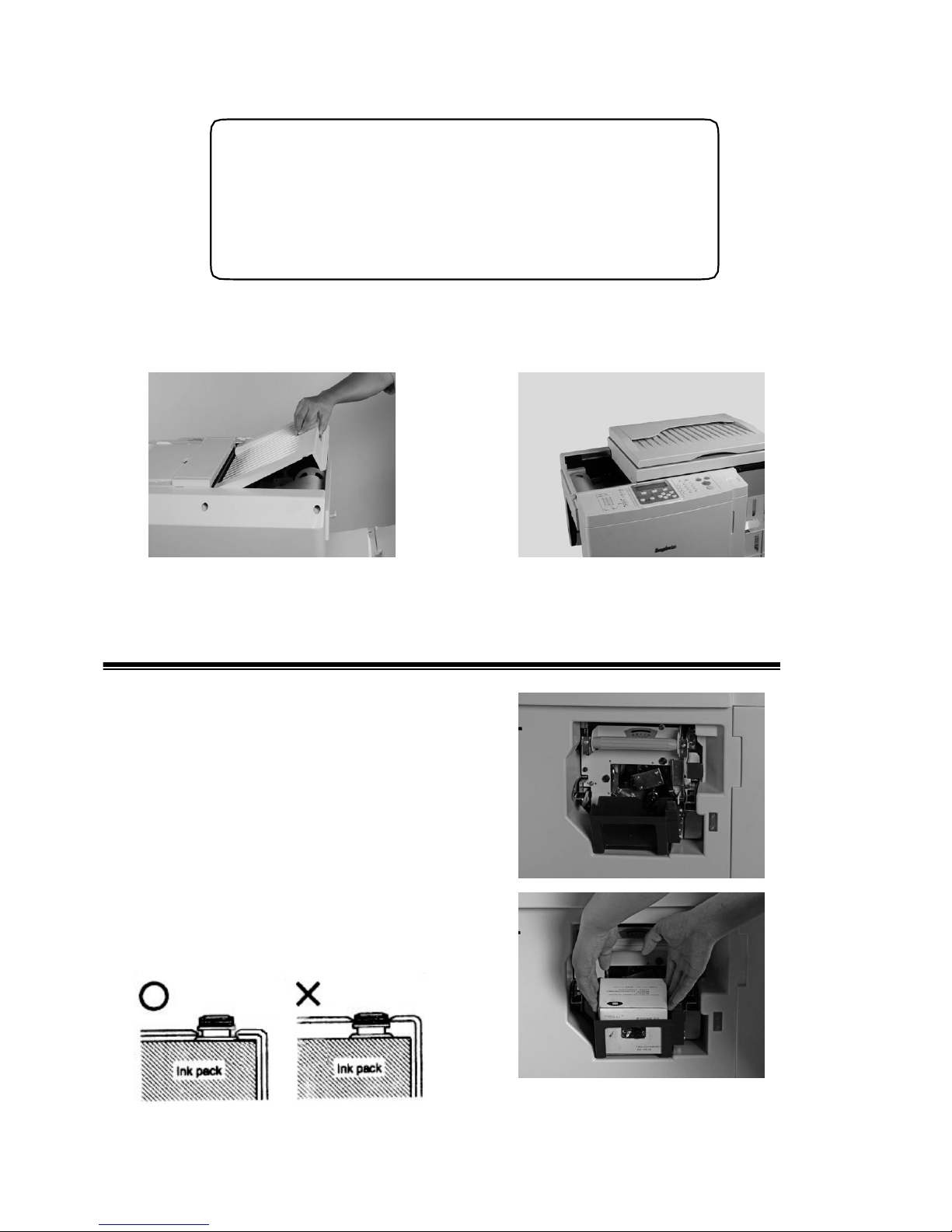
BPS 201
)
BPS 101
◆Warning!
The process of cutting master includes process of cutter
returning to its start point. Don’t take out the master head piece
until the whole cutting procedure is completed. It’s dangerous,
please be careful.
5. Close the original receiving tray( Close the scan flat (
)
5. Installation of the Ink
1. Open the front door, press down the ink case switch;
2. Open the ink cover, make sure the ink mouth
groove connect to”U” mouth of the drum. Correct
installation;
29
Page 32
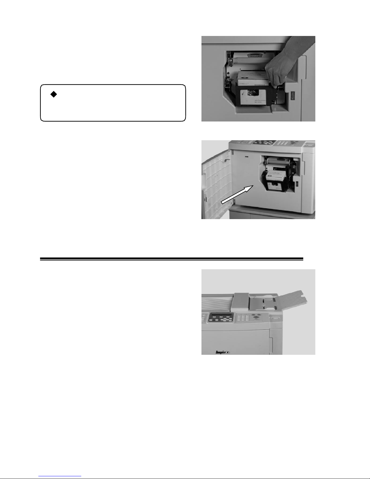
work between the ink cartridge and the ink pump
BPS 101
3. Lock the ink holder tightened, or else the air will be
leaked in and the ink can not be well pumped in. The
nozzle can be adjusted by the adjusting bolt;
Notes
Do not keep the opening ink in the air
long time
4. Close the front door.
6. Placement of the Original
1. Open the original support tray(
)
;
30
Page 33
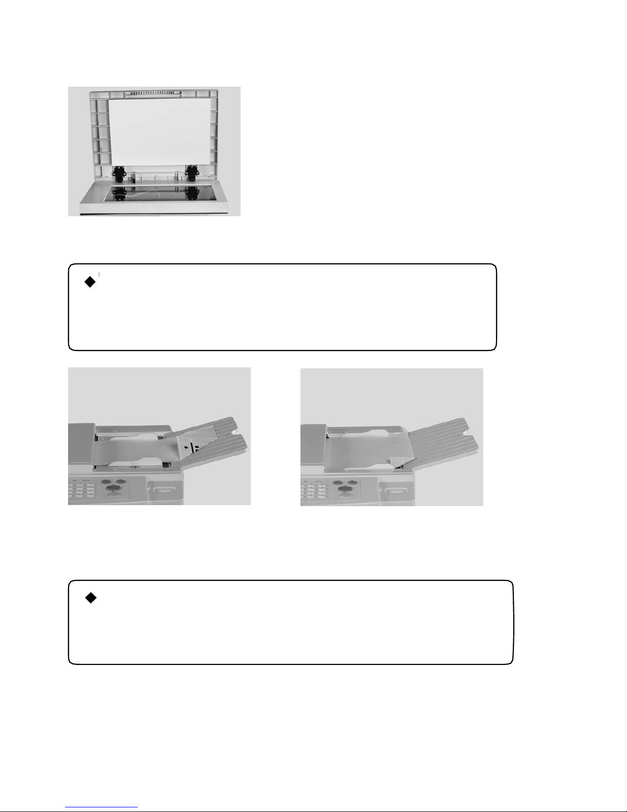
BPS 201
;
)
BPS 101
BPS 201Open the scan cover(
)
2. Place the original on the original tray, with image side adown.(
Notes:
Zoom function is available for B5 and A5 size orginal when they are
placed in both vertical and horizontal direction. A3 and B4 original is
normally functioned only in vertical palcement.
31
Vertical placement Horizontal placement
Put the original in the middle and close to the left glass flat (The image side adown)(
)
Note:
Zoom function is available for A4,A5 and B5 size orginal when they are placed in
both vertical and horizontal direction. A3 and B4 original is normally functioned
only in vertical palcement
Page 34
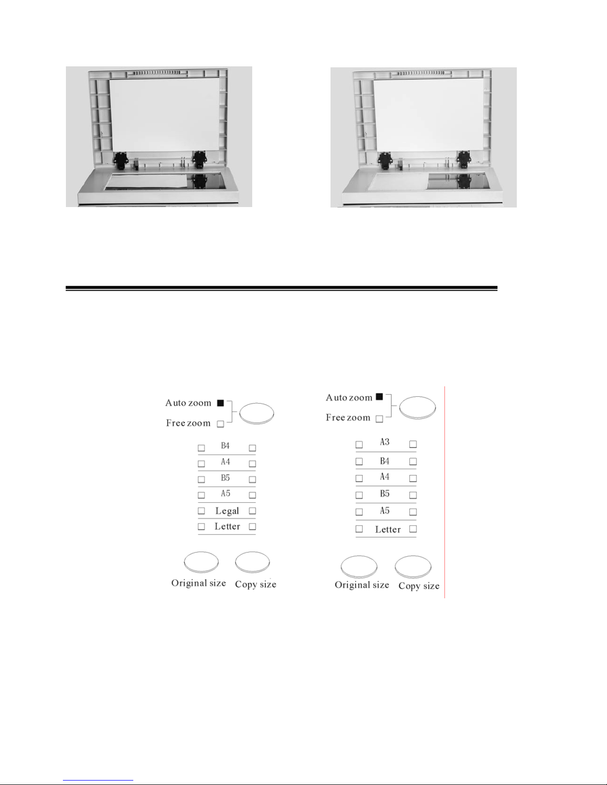
32
Vertical placement Horizontal placement
7. Choose Paper Size
Choose original size and copy size, eg. choose original size A4 and copy size A4, operation details as
below:
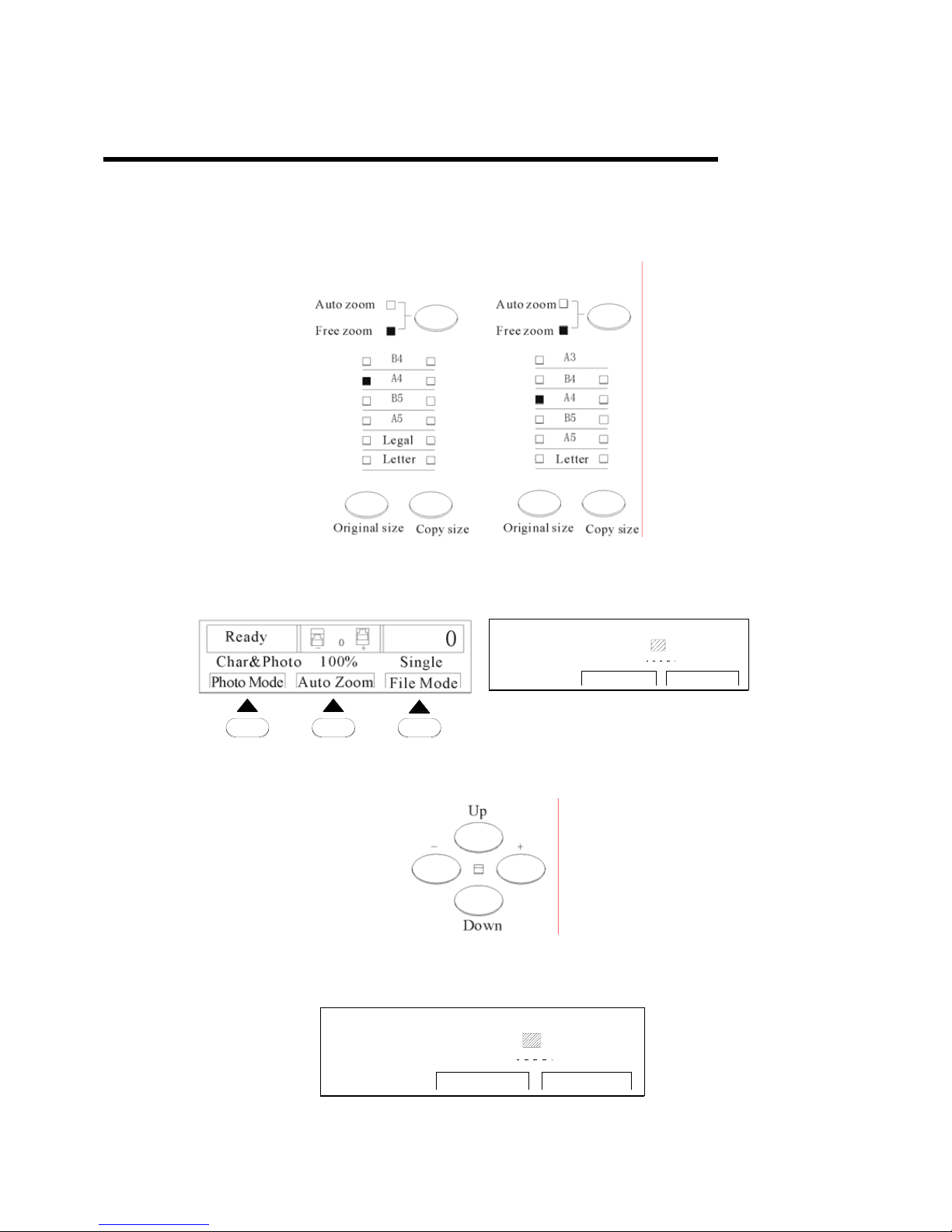
1. Check and make sure automatic zoom rate indicator light is on, if it isn’t on, press the zoom rate key
for conversion
Page 35
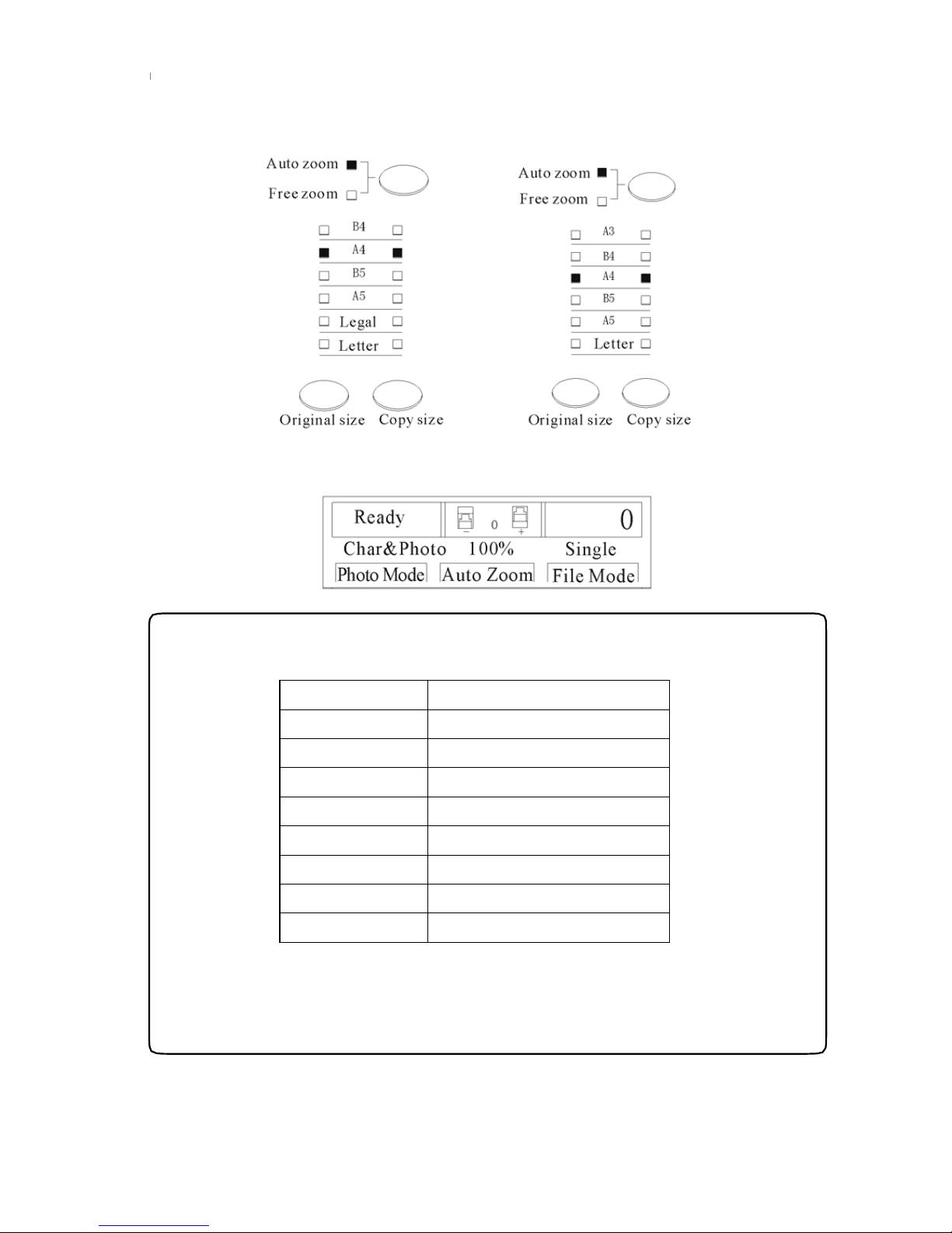
2.Press the “original size” key to select A4, and the A4 indicator light is on.Press the “copy size” key to
select A4 and the indicator light A4 is on;
3. LCD display:
33
◆Notes:
Europe
Paper size A(±1%)×B(±1%)
A3 291mm 414mm
A4(R) 204mm 291mm
A4 291mm 204mm
B4 251mm 358mm
A5(R) 204mm 142mm
A5 142mm 204mm
B5 251mm 176mm
B5(R) 176mm 251mm
● When use the paper smaller than original size without choosing paper size,
the inside of machine and the printout might be polluted.
● If the paper size is not correctly set before making master, the printout will
not be correct.
Page 36

8. Master Making
1. Press the master-making key and start master making;
试印
制版
印刷
停止
Test print Master-making
Start
Stop
2. After master making, one sheet of test printout automatically follows;
3. Check whether the print image is in the center of the printout, if not, please check if the original and
the print paper are located in center.
◆Notes:
If print number is input before master making, after master making, the machine will directly print
according to the input number without test printout.
34
Page 37

9. Printing
1.Set the printing number by pressing numeric key;
故障
35
数据传输
123
456
789
0
清除 复位
Error
Dada transmission
ResetClear
◆Notes
● Max printing number set 9999 sheets.
● If wrong number is input, press “*” key and set a new number.
2. Press the start key and start to print. The set print number decreases. The printouts are delivered onto
the receiving tray;
试印
制版
印刷
停止
Test print Master-making
Start
Stop
3. The machine stops automatically after printing work is completed, and then the initial set printing
number will be displayed.
◆Notes
● Press “stop” key if you need stop printing when the number is not zero, and press start key when
you need restart printing.
Page 38
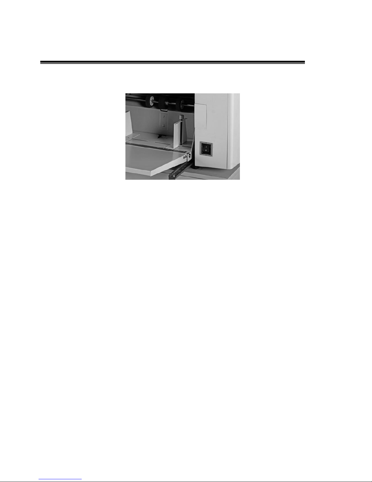
10. Turn off the power
1.Turn the switch to“O”position and turn off the power.
36
Page 39

Chapter 3
Printing Operation
This chapter introduces how to operate the machine on all functions.
Enlargement and Reduction———————————————————38
Automatic Zoom———————————————————————39
Free Zoom——————————————————————————41
Density Adjusting———————————————————————42
Scan n i n g D e n s i t y Adjus t in g ———————————————————42
Master-making Density Adjusting —————————————————43
Printing Density Adjusting————————————————————43
Ch a r / C h a r &Pho t o / P h o t o Mode ——————————————————44
Two in one Master Making————————————————————45
Book Mode——————————————————————————47
37
Page 40
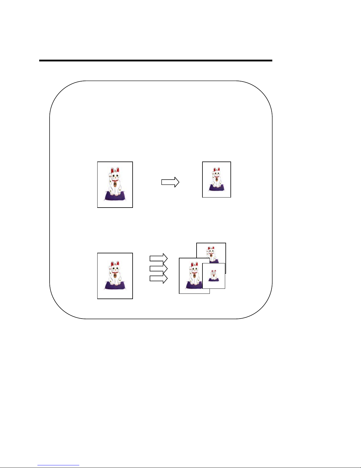
Enlargement and Reduction
To set enlargement and reduction according to the sizes required.
■Automatic Zoom Rate(Page 41)
Machine choose the zoom rate automatically according to
the size of original and copies.
B4 document A4 printout
■Free Zoom Rate (Page40)
Document printout
38
Page 41
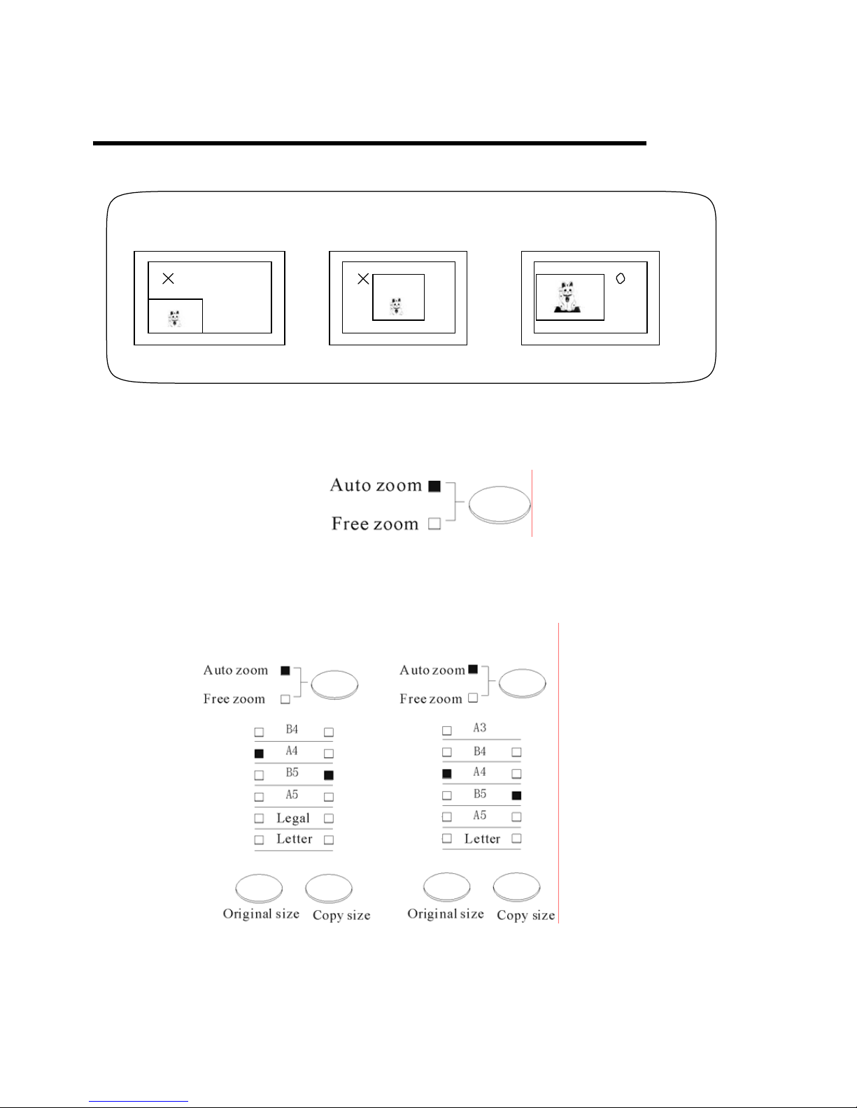
Automatic Zoom
Basic Print Process 1-6 step(Page 24-33)
Incorrect Incorrect Correct
39
1. Set “Automatic zoom rate” light on. If “Free zoom” light is on, press conversion button to switch the
“Automatic zoom” light on;
2. Select original size by pressing “Original document size ” button. For example:A4. Press ”Copy
size” to select. For example:B5;
BPS 201
BPS 101
Page 42

3. LCD screen display:
◆Indication:
Make sure to return the settings back to standard zoom rate
● According the steps 1-2 above select “B4” for original documents size and “B4” for copy size.
● Press “Reset” key (All clear) back to original setting mode.
Press “Master-Making” key to start making master.
40
Page 43
Free Room
1.Press the zoom switch button and the “Free Zoom” indicator light is on. Press “Original document
size” button to select original paper size. E.g. :A4.
2.Press “Free zoom” button to enter free zoom interface.
+
-
50% 200%
100
%
就绪
图文
100%
0
图像模式
文件模式
单页
0
-+
手动倍率
3.Press cursor button “-” and “+” to set adjustment from 50% to 200%.
4. Press “Confirm ” button to confirm.
+
-
50% 200%
110
%
41
BPS 101 BPS 201
Page 44
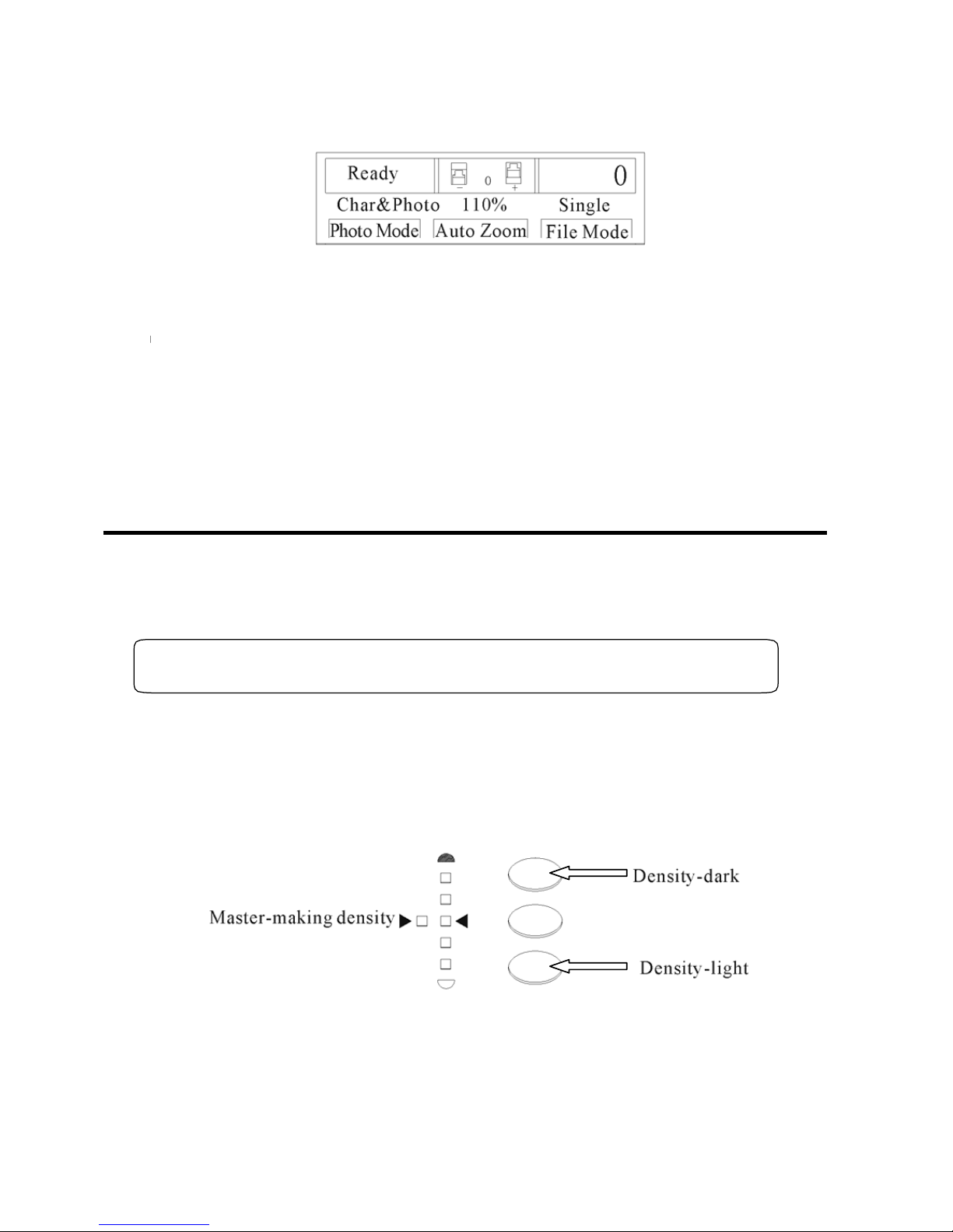
5.LCD Screen:
◆Back to Zoom Standard Mode:
● Press zoom switch button or reset button.
Press “Master-making” key to start master making.
Density Adjusting
Scan Density Adjusting
Adjust the scan density in 5 levels. There are 5 indicator lights, lighter, light, normal,
dark, and darker. Increase density if original document is too light, while decrease the
density if the original is too dark.
◆Choose “density” before master making.
Such as :Set the density to light.
Press density adjusting buttons (including density-light button and density-dark button) as below in the
operation panel to adjust the density. Press density-light button when you want to set light scan density.
Note:When the left light is on, it is master-making density adjusting.
◆Indication
Back to scan density standard setting.
Press density adjusting buttons until the middle light is on.
42
Page 45
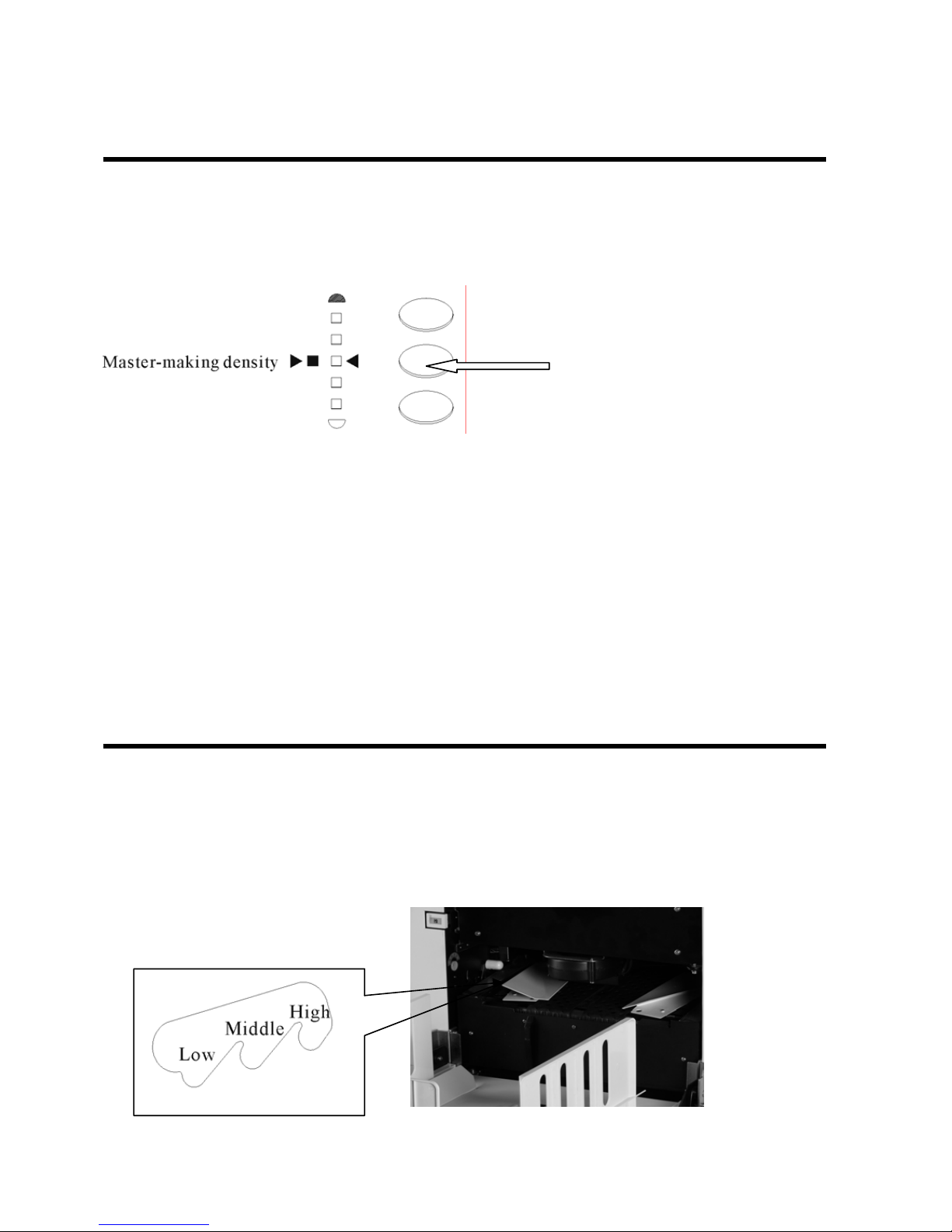
Master-making Density Adjusting
5 steps for master making density, lighter, light, normal, dark, darker, which are indicated by 5 density
light.
1. Press density switch button (the middle button) as below, then the signal light will be on.
2.Press density adjusting buttons to select the printing density.
3.Back to select the scanning density after press density switch button, then the indicator light of
density switch is off.
◆Back to scanning density in standard settings.
● Adjust according to step1---2 until the middle signal light is on.
Printing Density Adjusting
3 levels for printing density.
Adjust the printing density by increasing or decreasing the pressure of the pressure roller.
Turn it to high level, the printin g dens ity is dark.
Turn it to low level, the printing densi ty is light.
43
Page 46
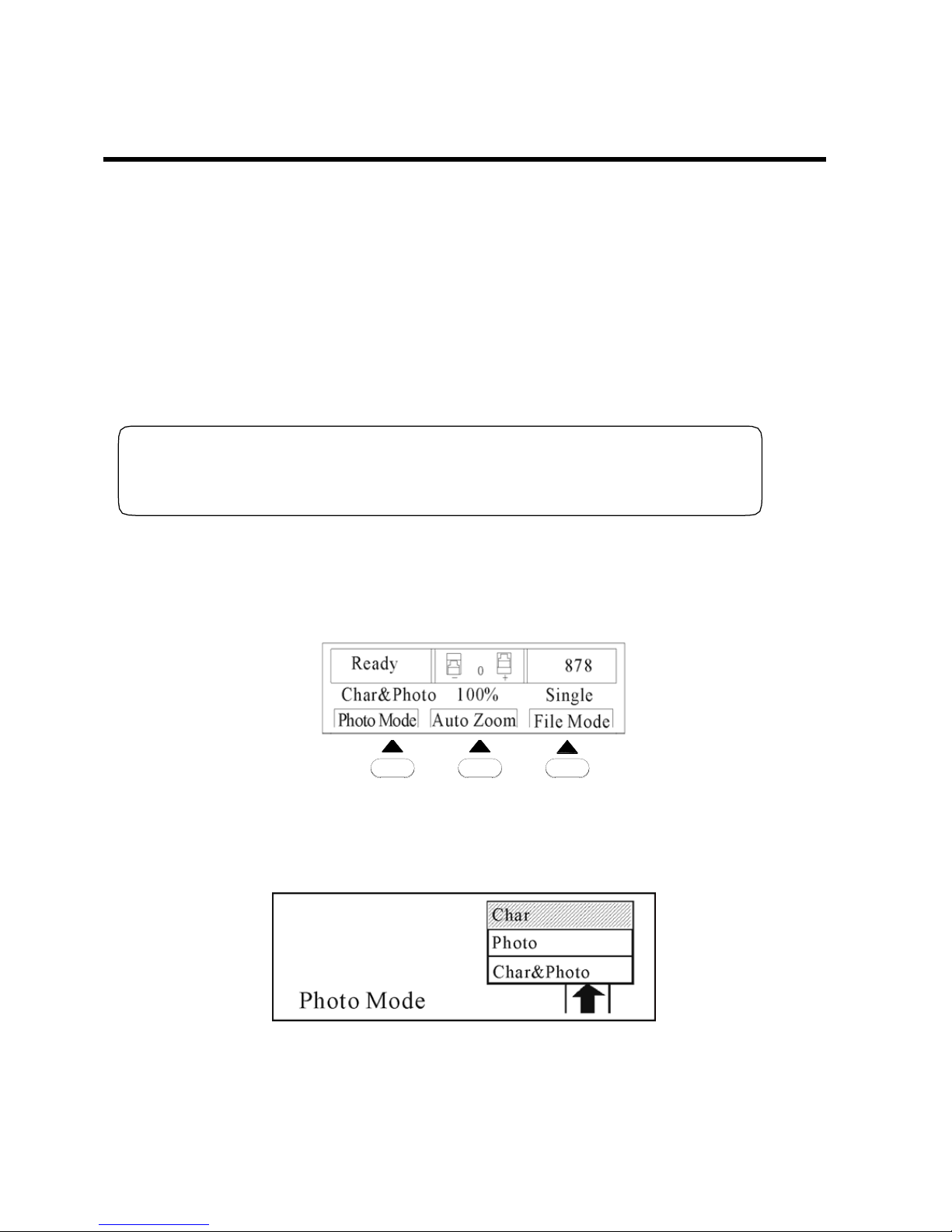
Char/Char&Photo/ Photo mode
3 modes for this function:
●Char mode:for text print.
Original: Text original
●Photo mode:for photo print.
Original: Photo original
●Char&photo:for print of original mixed with text and photo.
Original: Original mixed with text and photo
◆Note
Select photo modes before master making.
For example, when the original is letter file, please choose “char” from the Photo Mode.
1. Press “Photo Mode” button in the display.
就绪
图文
100%
图像模式
自动倍率
文件模式
单页
0
-+
878
2.The screen displays “Photo mode”, and the indicator light of cursor keys is on. Press cursor keys
Up and Down keys to enter “Char” Mode. Press confirm key.
44
Page 47
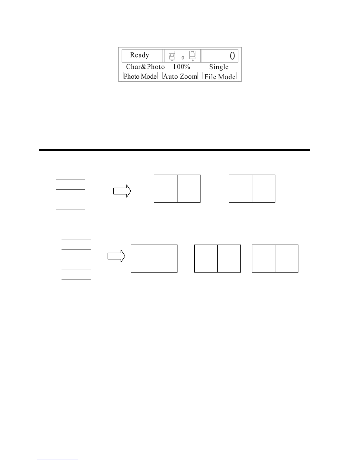
3.Main screen display:
Press “Master-making” button to make master.
Two-in-one Master Making
Under Two-in-one master making mode, 2 sheets of original can be plated into one sheet of master,
which is for book making.
1
2 1 4 3
2
45
3
4
Documents(even number) Printout1 Printout2
1
2
3
4
5
2 1 4 3 5
Documents(odd number) Printout1 Printout2 Printout3
Page 48
right
output except the standard paper size.
Only standard size paper is ensured the correct printout, You can not get the
BPS 201
◆Notes
● Select “Two-in-one”mode before master making.
● If 100% zoom rate is selected, set the original size equals to combined size of 2
sheets of original.
● Under zoom rate other than 100%, please pay attention on the following points.
● Make sure after zooming, the combined size of the 2 sheets of original is same as
the copy paper size.
●
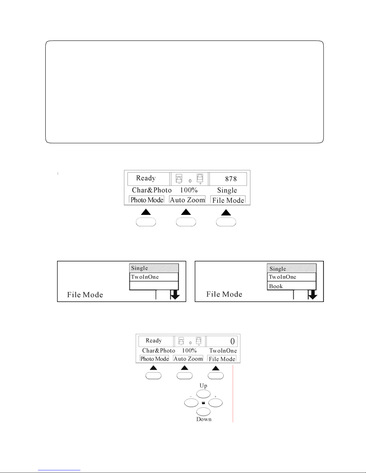
1.Press “File Mode” button to enter file mode;
就绪
图文
100%
图像模式
自动倍率
文件模式
单页
0
-+
878
2. LCD screen displays “File mode” interface;
文件模式
单页
二合一
文件模式
单页
二合一
书刊
3. The indicator light of cursor keys is on, press Up Down buttons to choose “Two-in-one”mode or book
mode ,then press “confirm ” button to confirm.
46
BPS 101
Page 49
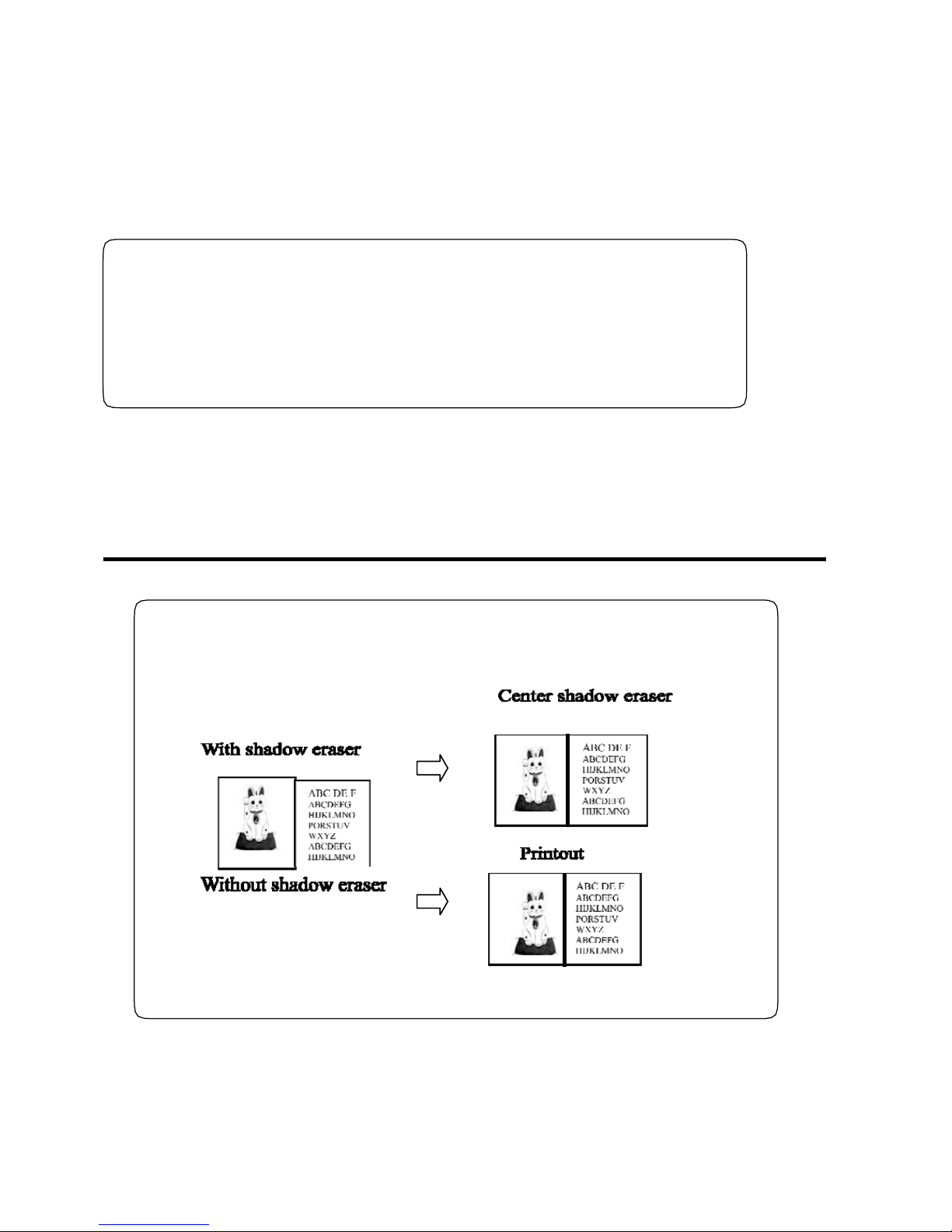
Book Mode(BPS 201)
Back to standard mode settings:
● Press “File Mode”, choose “Single”, and press” Confirm” button. Or
Press “#”(All clear) button, back to the standard mode settings.
Press “Master-making” button to start master making.
47
◆Indications
If the printout is incorrect, please check below:
● The direction of original document.
● Original size ,paper size and zoom rate .
Book mode
Under book mode, the book shadow or the shadow of folded original can be erased
automatically.
Middle shadow erase
The middle shadow with width of 15mm is erased.
Page 50
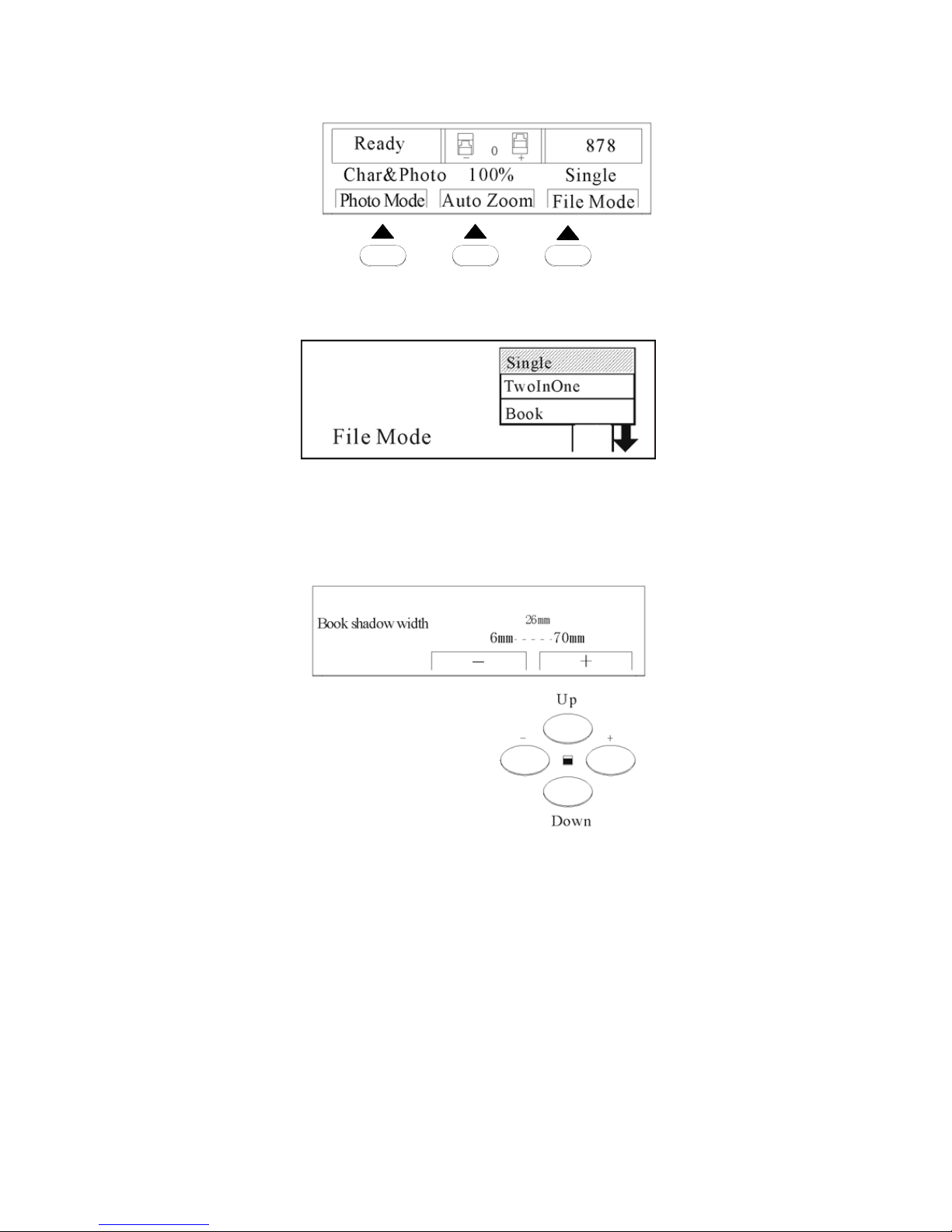
1.Press “File Mode” button;
就绪
图文
100%
图像模式
自动倍率
文件模式
单页
0
-+
878
2.LCD displays “File mode”;
3. Press cursor keys “Up” and “Down” to enter “Book” mode. Press “Confirm” to enter adjustment of
book middle shadow. Press cursor keys “+” “-” to adjust the book middle show as showed below.
Press “Confirm” button to confirm.
◆Indications
Back to standard mode setting:
Press “File Mode” to “Single” and press “Confirm” key. Or
Press “#” (All clear) button, back to the standard settings.
Press “Master-making” button to start making master.
48
Page 51

Chapter 4
Other Functions
This chapter describes other functions, such as : total count display, printing
speed, printing position adjustment, energy save, password, computer
connecting and other functions.
Counter Display Function———————————————————50
Printing Speed Adjustment———————————————————51
Printing Position Adjustment——————————————————52
Power Save Function—————————————————————53
Confidential Function—————————————————————53
Computer Print Function————————————————————54
The Instruction of Driver Installation———————————————55
49
Page 52
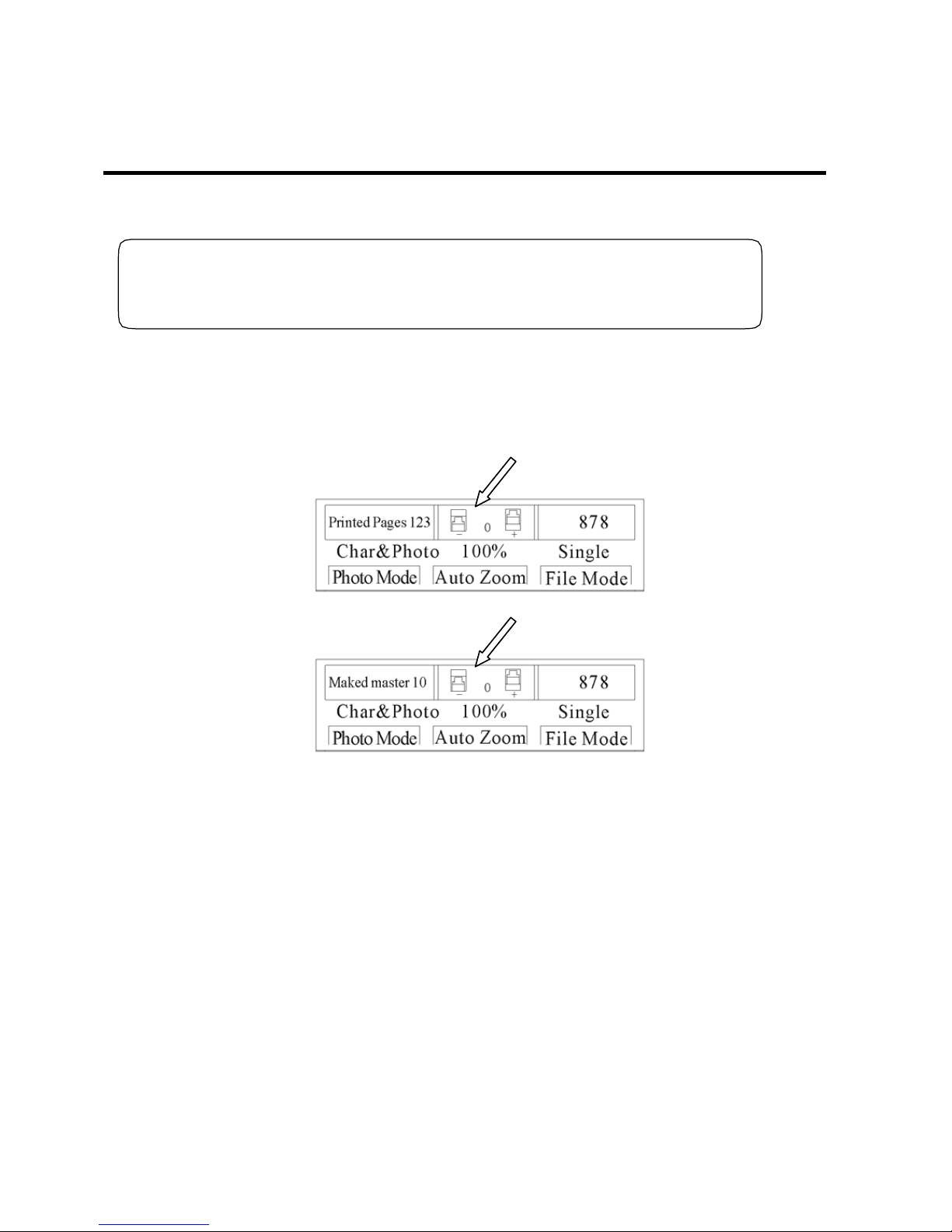
Counter Display Function
1. Check and confirm the machine stops printing;
◆Notes
If the machine is printing, please press “Stop” button to stop printing.
2. Keep press “Stop” button, the total count of printing and master making will be displayed. See
following figure: Total count: 123, Total master making: 10. Loose “Stop ” button, and the machine is
back to original mode.
50
Page 53

Printing Speed Adjustment
5 levels of printing speed,55 ppm, 70 ppm, 85 ppm, 105 ppm, 120 ppm, the 5 indicating lights indicate
5 levels of printing speed. Default setting is 85ppm, which is indicated by the middle light. The indicate
light being on indicates the ongoing print speed.
◆Indications:
● In case the continual jam happen on certai n type of paper or certain image paper,
please increase or reduce the printing speed to solve this problem.
● Under high speed printing, printout is light ,while under low speed, printout is dark.
● The printing speed adjustment is effectual during printing process.
Reduce the speed:
Press “SpeedL”button, indicator light is moving toward left, and the printing speed decreases.
Increase the speed
Press” SpeedR” button, indicator light is moving toward right ,the speed
increases.
◆Indications:
Two methods are used to set back to standard settings:
● Press “SpeedL” button or “SpeedR” button unt il th e middle indicator light is on.
● Press “#” (All clear ) button to back to the standard mode.
51
Page 54
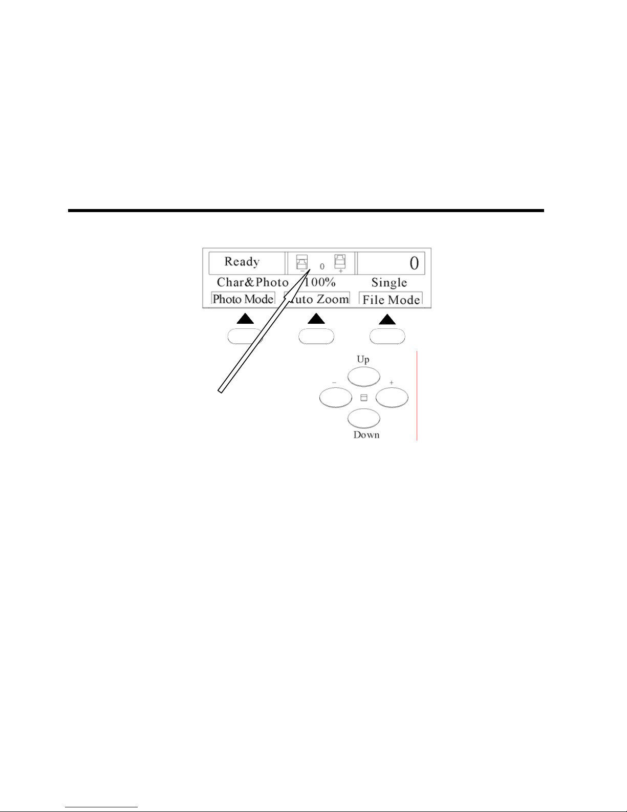
Printing Position Adjustment
Printing position is still adjustable after master making. (Horizontal±10mm )
◆Indications:
The printing position is not adjustable during the printing process.
Printing Position Adjustment
1. Press “+”and “-”keys indicated by the arrow as showed in the picture.
就绪
图文
100%
0
图像模式
自动倍率
文件模式
上
下
-+
单页
10
-+
◆Indications:
Two ways of setting to turning back to the standard position:
● Press “+” “-” keys until the printing position is “0mm”.
● Press “reset” button.
52
Page 55
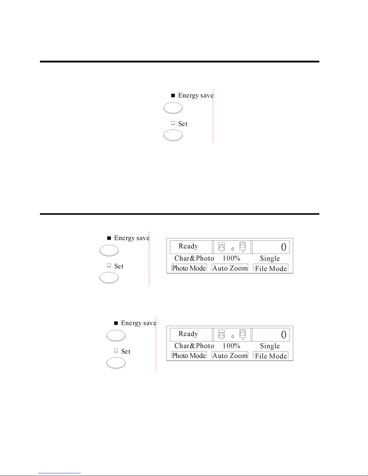
Power Save Function
1. After press “Energy save” button, LCD will become black without any display. All of the indicator
are off (Except save energy indicator light );
2. Press any button to exit from save energy mode.
Confidential Function
1. Press “Set” button and the indicator light of setting button is on. LCD displays “Input
New Password”;
2. Press the numeric keys to input 4 digit password, for example “1234”, then press “confirm ” button.
The screen displays “Input password”, and please input the password “1234”. Press “Confirm” button
and the main display shows “Ready”.
Remark:If the user wants to change the password, press “set” button, input new password and then
press “Confirm” button. Without any operation, the machine will automatically lock in three (3) minutes.
The machine shall save the password as memory after the password is set, so the password must be
input every time the machine is turned on. If the user wants to cancel the password setting, first turn off
the machine, then press “Energy save” button and “Set” button synchronously, and switch on the power.
In this way, the password is canceled. If the user wants to set a new password please follow the steps
above.
53
Page 56
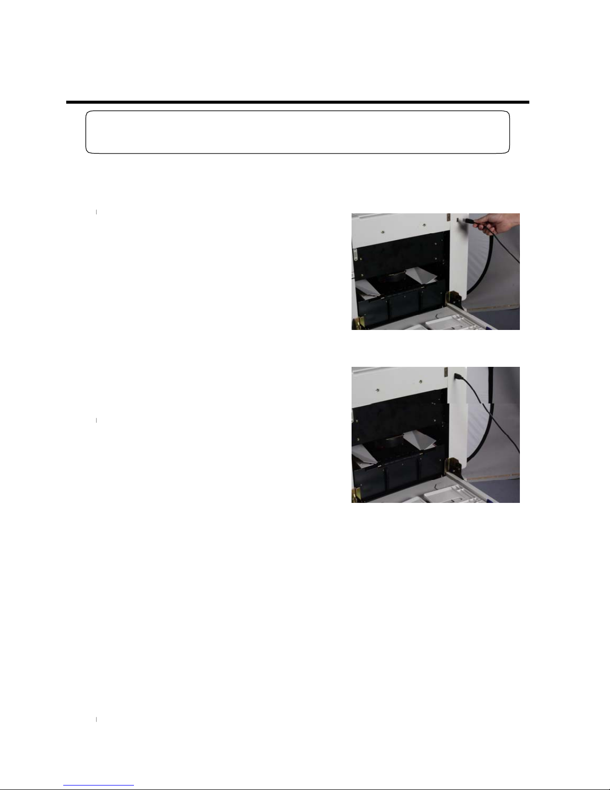
Computer Print Function
◆Note:
Please refer to the instruction of driver installation for cable connecting and setting.
Steps 1—7, the basic print process (Pages 24---33)
1. Plug the USB cable into the digital duplicator and the
computer;
2. Connect the USB cable;
3. Operate the print command according to the computer operation system.
◆Indications:
After master making and print are completed, more operations can be executed on the control panel.
54
Page 57
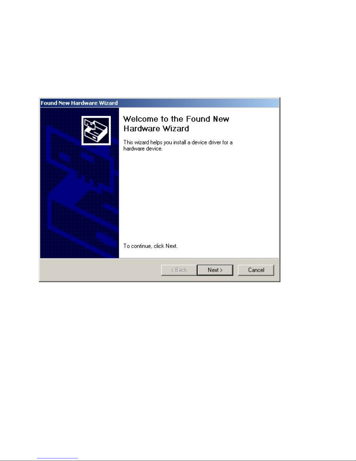
The Instruction of Driver Installation
Please install the driven procedures according to the following steps:
Step 1: Plug the USB cable into the printer and the computer. Then Turn on the printer.
Step 2: The following dialog box appears:
Then click Next.
Step 3: The following dialog box appears:
55
Page 58
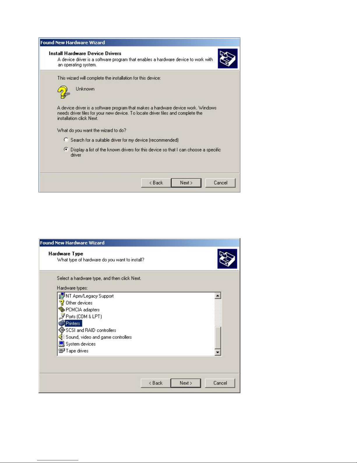
Check the second option. Then click Next.
Step 4: The screen now displays Hardware Type. Select Printer, then click Next:
Step 5: The following dialog box appears:
56
Page 59
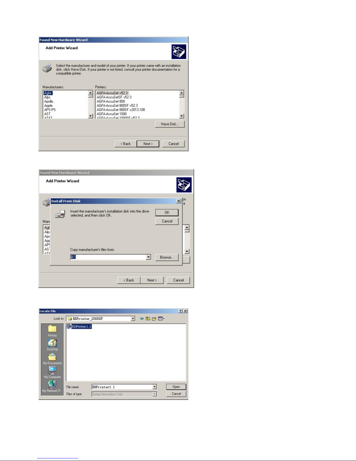
Click Have Disk.
Step 6: The following dialog box appears:
Click Browse.
Step 7: Browse the path of the driver. The screen displays like following:
Select the file RDPrinter1.1 .inf, then click Open.
57
Page 60
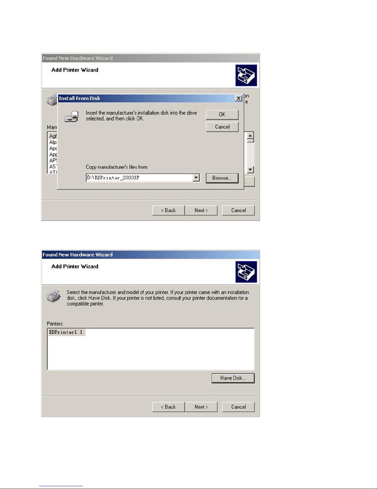
Step 8: The following dialog box appears:
Click OK.
Step 9: The screen displays the Printer Name:
Select the proper printer, and then click Next.
Step 10: The following dialog box may appears:
58
Page 61
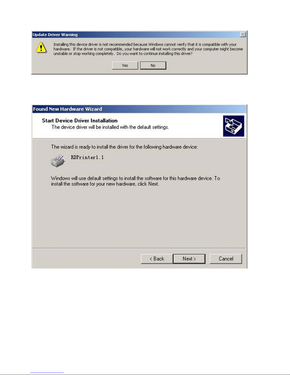
Click Yes to continue installing the driver.
Step 11: The following dialog box appears:
Click Next.
Step 12: The following dialog box may appears:
59
Page 62
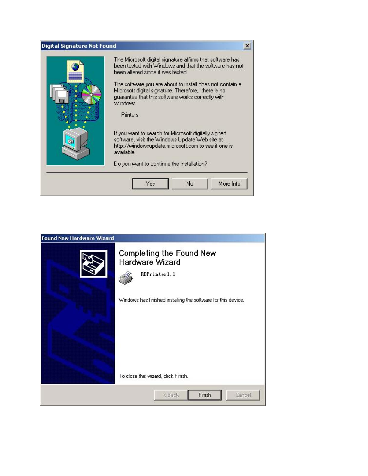
Click Yes to continue the installation.
Step 13: The following dialog box appears:
Click Finish to complete the driver installation.
60
Page 63

Notes: The driver procedure above applies to BPS 101,BPS 201,BPS 301 etc.
61
The installation instruction above takes Windows XP as an example. The installations are similar in
other operation system, and please just follow.
In case the installation fails please enter the printers in the control board, cancel RDPrinter1.1, click
right key of the Mouse on the blank and enter the server attributes, click driver procedure and cancel
RDPrinter1.1. And then reinstall according to the steps above.
Remarks: This driver procedure is normally operated under Windows2000 and WindowsXP.
Page 64

Chapter 5
Consumables Replacement
This chapter describes how to replenish supplies and dispose of them regularly.
Ink Replacement———————————————————————63
Master Replacement——————————————————————65
Taking out Disposal Master———————————————————67
Printing Paper Replacement———————————————————69
62
Page 65
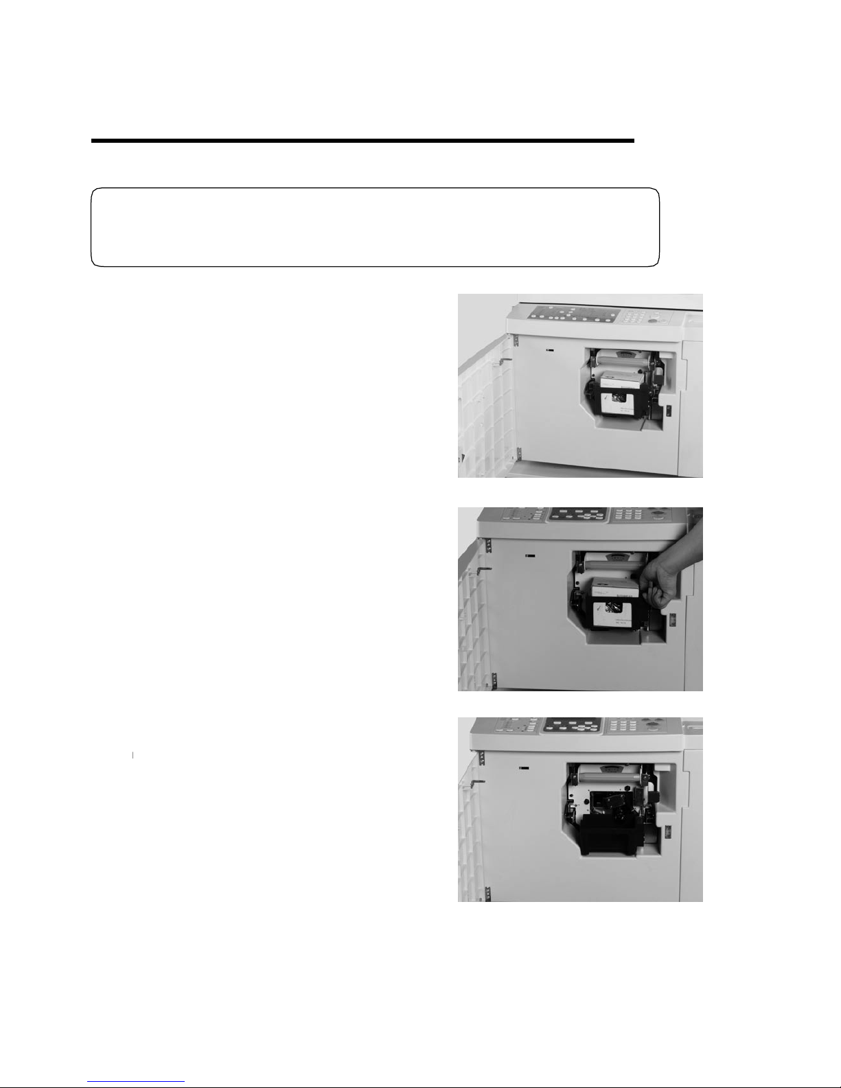
Only Blue ink is applied to this machine.
Ink Replacement
LCD displays“Ink over”, when the ink in the cartridge is used out. Please replace ink as follows.
◆Notes
1. Open front cover;
2. Press down the drum lock switch;
3. Take out the empty ink case;
63
Page 66
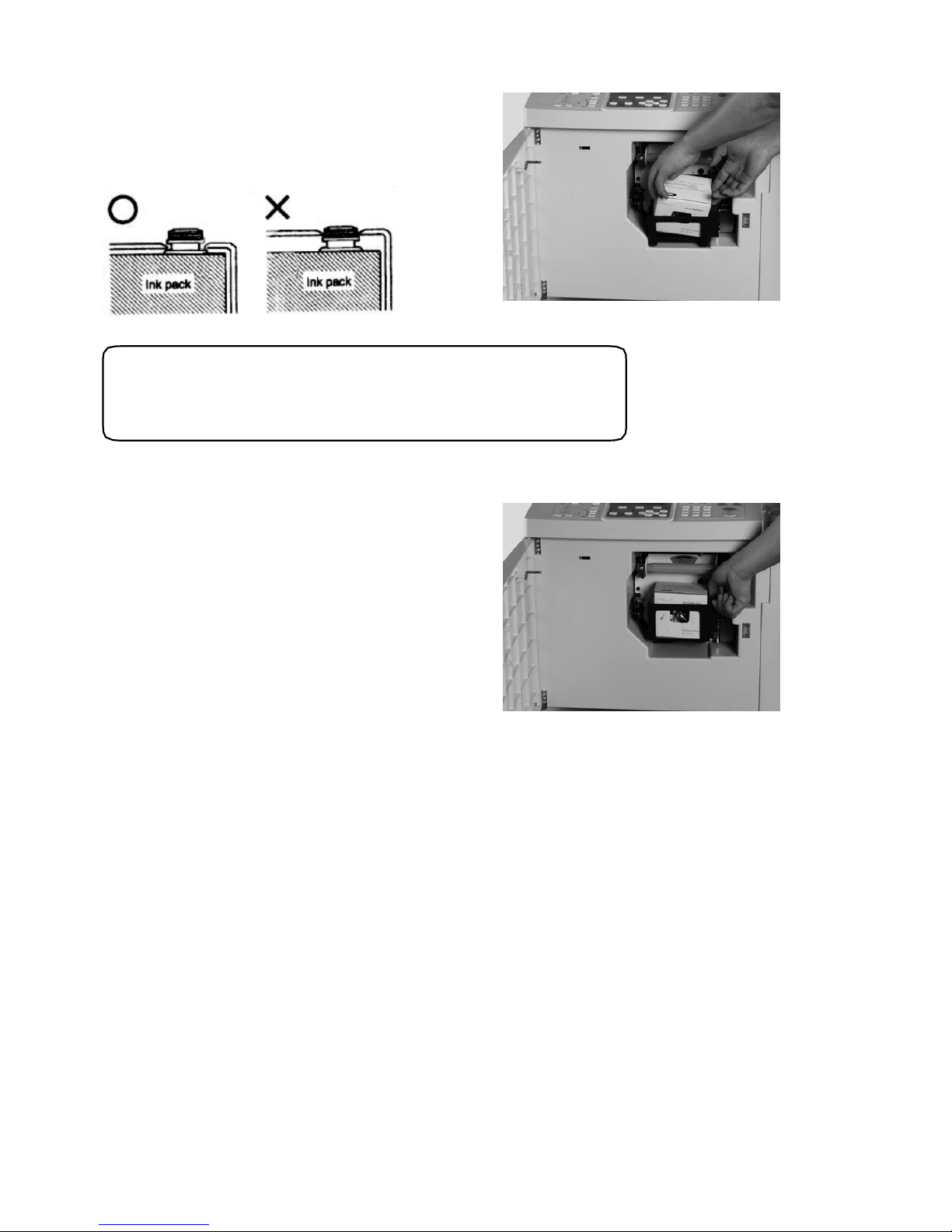
4. Open the new ink cover, insert
the groove of the ink nozzle to be the
“U”mouth on the drum;
◆Notes
Don’t keep the opening ink exposed in the air for long.
5. Support and push in the ink holder, and
lock it tightly. (The air is not allowed to
leak into the ink pump, otherwise the ink
can not be pumped in well).
6. Close the front cover.
64
Page 67
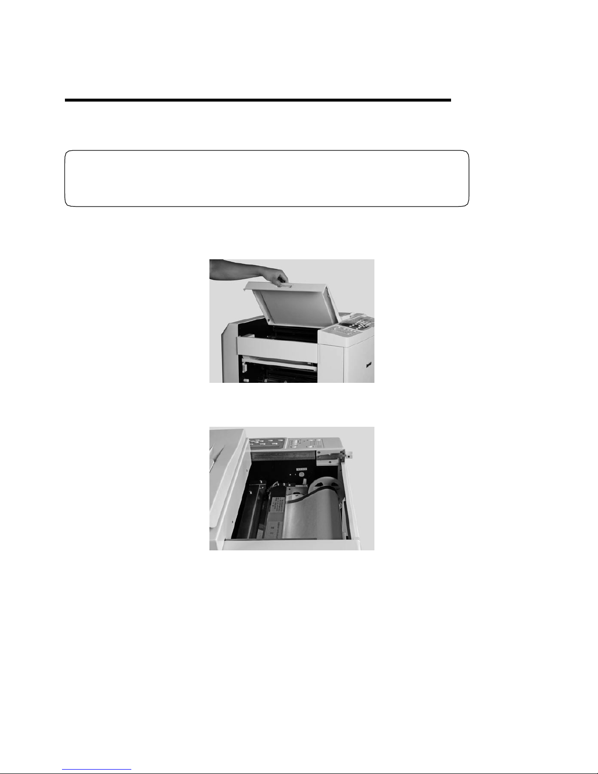
Only Blue master is applied to this machine.
for BPS 101
Press down the scan lock lever, and push the scan flat . for BPS 201
Master Replacement
When the master roll is near to the end, LCD displays “Master on Error” or“Master over” ,
Please replace the master as follows.
◆Notes
1. Open the original paper receiving tray .(
)
;
)
65
(
Page 68
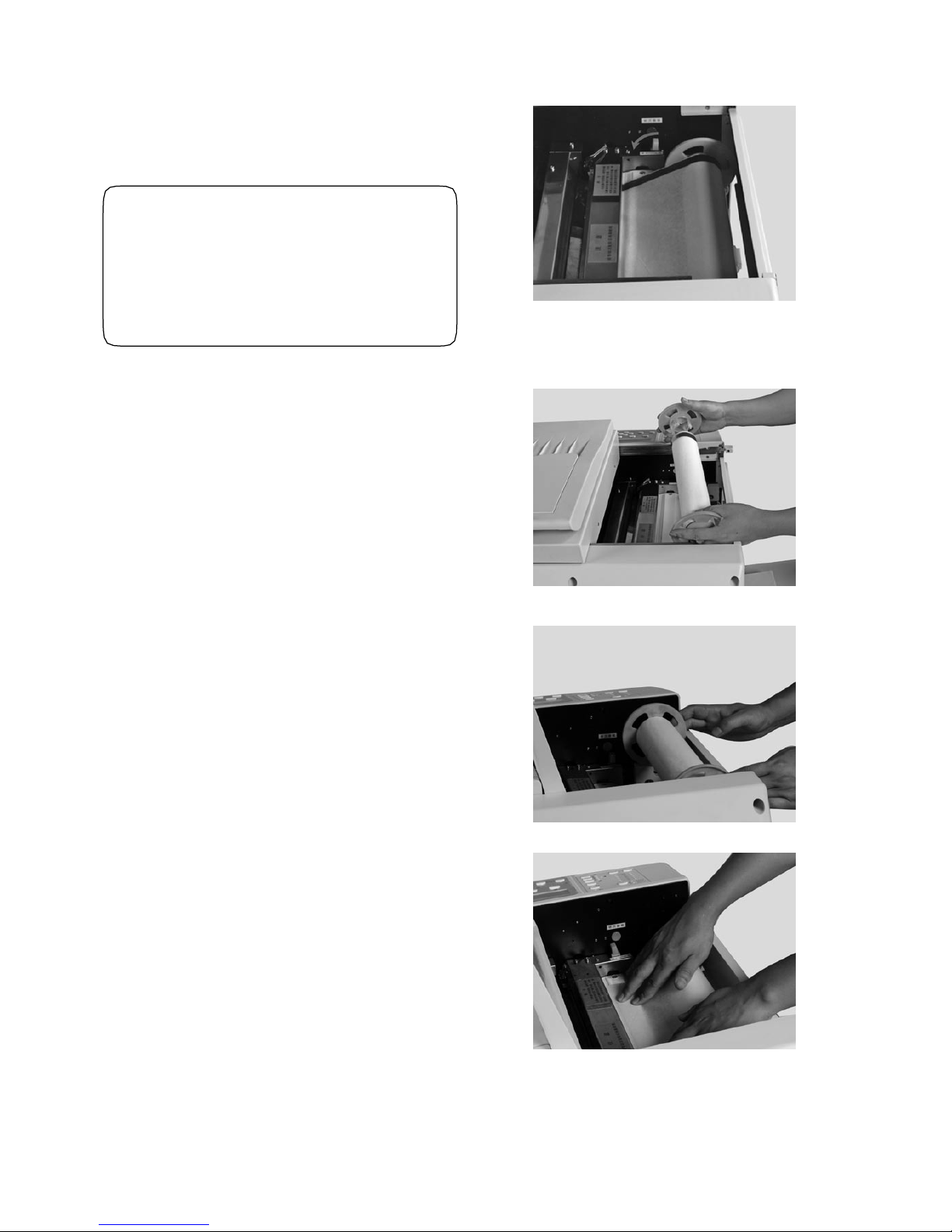
2. Press down thermal head releasing
lever to “Open” position;
◆Notes
Don’t touch the thermal head,
otherwise the thermal head might
be scraped, which will effect
master making quality.
3. Rotate the master roll bracket, remove
the old master roll. Take out remaining
master jammed in the thermal head;
4. Please install the new master roll onto
the master bracket , and put it onto the
plating machine;
5. The smooth face of master should be
put downwards, extend the head of
master in the middle of the printing roller
and thermal head, lift down thermal head
releasing lever to “Close”;
66
Page 69
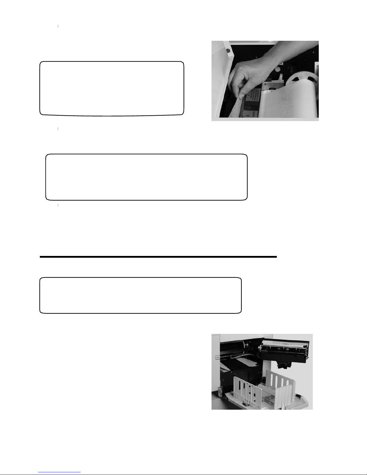
Only Blue waste master core is applied to this machine.
for BPS 201for BPS 101
6. Press cutter micro switch ,take out the
wasted master piece under cutter;
◆Notes
It’s back and forth in cutting.
Please do not touch paper cutting
to avoid danger.
7.Close the original paper receiving tray (
)
and scanning flat(
)
.
◆Notes
●Don’t take out warning sticker on the cutter cover.
●Moving cutter may cause hurt.
Taking out Disposal Master
LCD shows “Disposal box full”.
◆Notes
1. Press the master disposal box switch,
open the disposal master box up to max;
67
Page 70
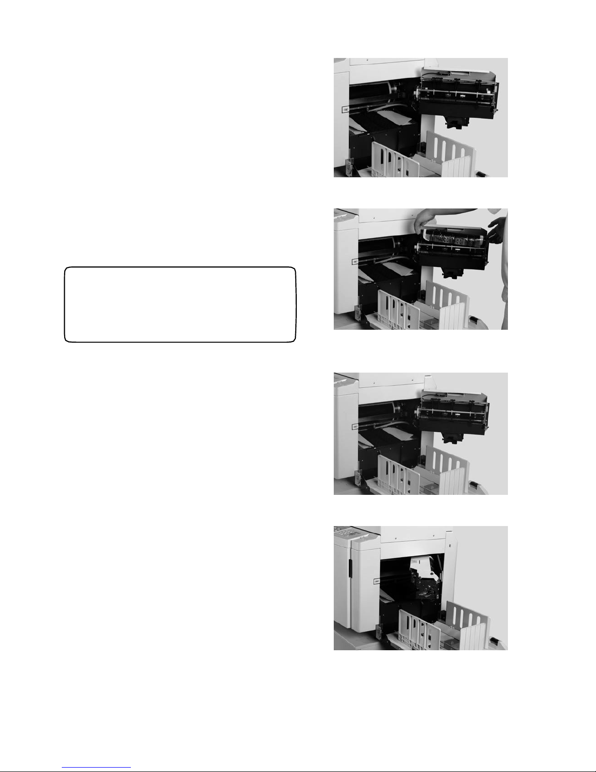
2. Press the cover switch and the cover
will be automatically sprung up;
3. Grasp both ends of roll core to take it
out and remove the disposal master from
roll core;
◆Notes
There is ink on the roll core ,
please take care of your clothing.
4. Put the roll core into disposal master box;
5. Close disposal maser box top cover ,
and close that box.
68
Page 71
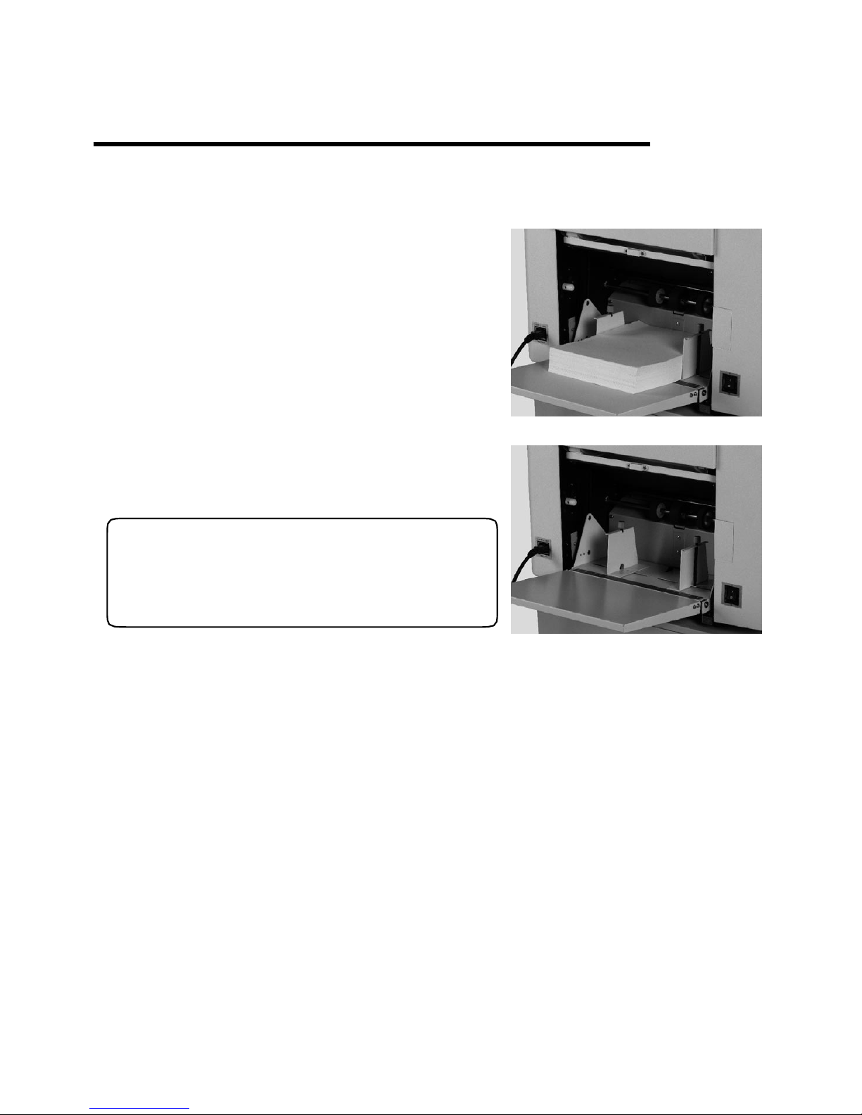
Print Paper Replacement (for BPS 101/BPS 201)
69
1. If the machine is in printing state please stop printing by pressing “Stop” button;
2. Press down paper feeding tray switch,
lift down the feeding paper tray;
3. Take out paper;
◆Notes
Please take it out if paper is jamming on the feeding
Roller.
4. Replace print paper, feeding paper tray lifts up automatically after press “Start” key.
Page 72

70
Chapter 6
Trouble Shooting
This chapter describes how to take care of problems that may arise with your
Rongda machines. Check the following information and the related items
before calling your authorized service department.
No Currency —————————————————————————72
Master Making/Printing Error———————————————————73
LCD Display Error and S im ple S o lution———————————————74
Placement of Drum———————————————————————76
Paper Empty —————————————————————————77
Paper Jam———————————————————————————78
Master Ejection Error —————————————————————81
Master Load Error———————————————————————83
Page 73
71
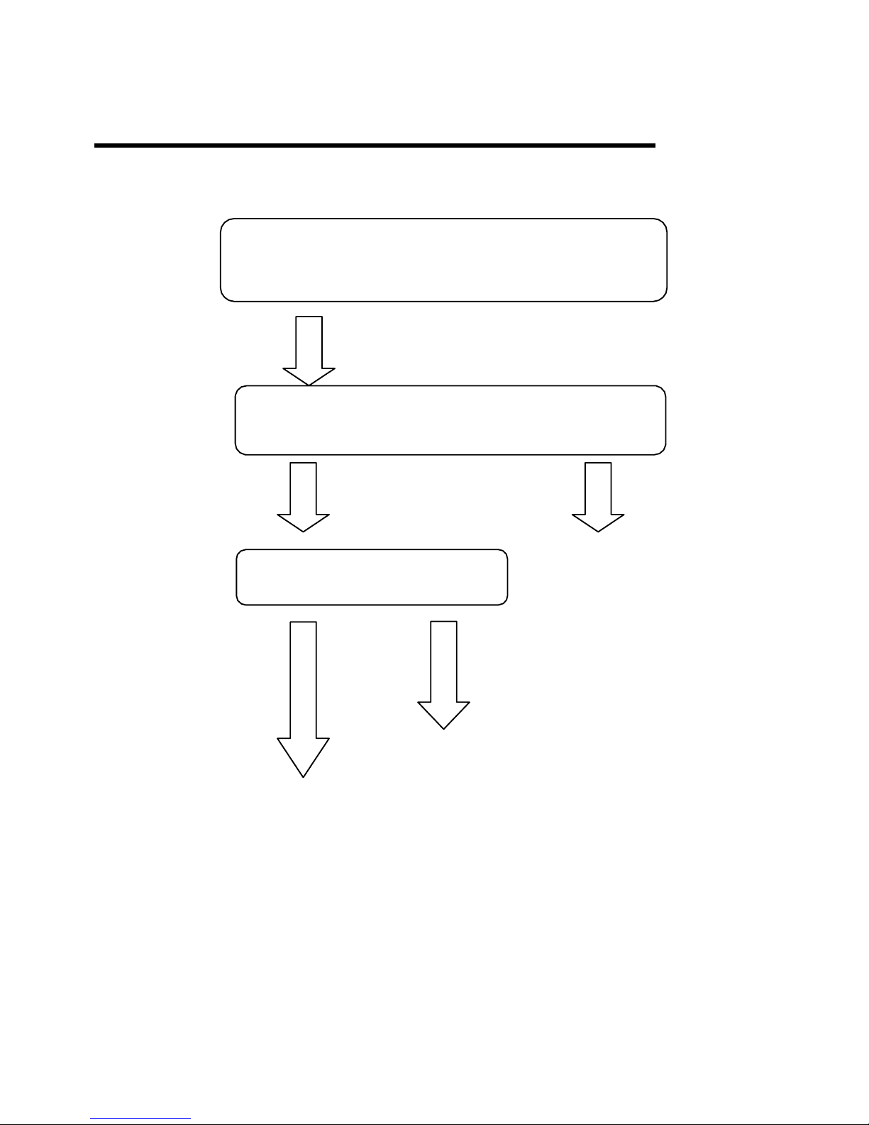
No Currency
If there is no power, please check as follows:
Whether the machine is switched on
Whether the machine is connceted to the power source
No
Yes
Connect to
the power
source
Whether the power is switched on
No
Yes
Switch on
the power
Contact the
Service Dept
Page 74
72
Master Making/Printing Error
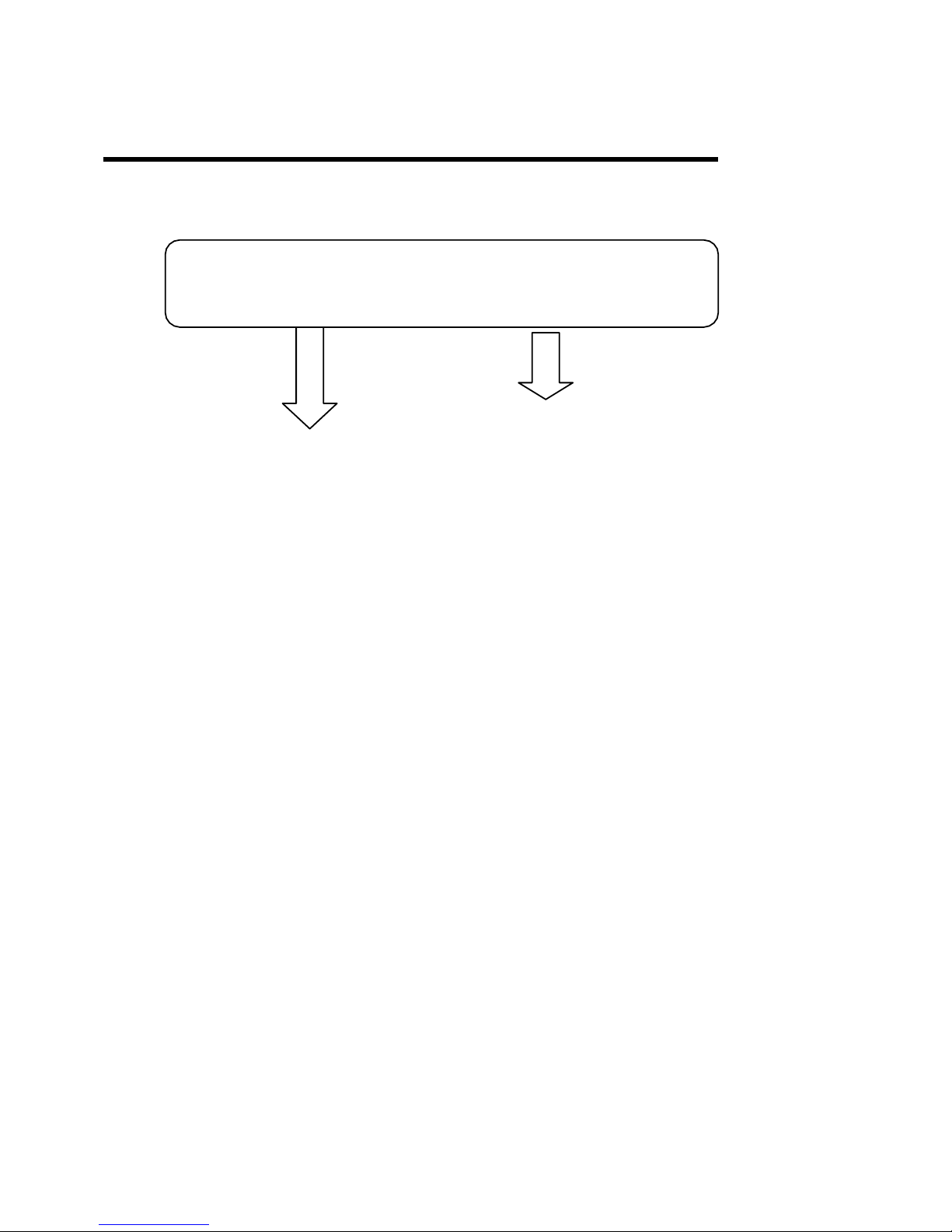
If the machine can not proceed with master making/printing, please check as follows:
Whether there is indication from the indicator light
No Yes
Contact the Service Dept. Refer to the indicated error information of the
next interface
Page 75

( for BPS 101/201
Place paper(BPS 101/BPS 201).
73
LCD Display Error and Simple Solution
Information Solution
Drum Lock Turn off the power and restart it. If the drum is still locked ,please contact Service
Dept.
Clamp Error Contact the Service Dept.
Clamp A Error Contact the Service Dept.
Clamp B Error Contact the Service Dept.
Clamp C Error Contact the Service Dept.
Unload Position
Error
Contact the Service Dept.
Space Motor Error Contact the Service Dept.
Cutter Motor Error Contact the Service Dept.
Fan Motor Error Contact the Service Dept.
Master-off Motor
Erro
r
Check disposal master box feeding mouth jams or not, if not, contact Service Dept.
Power Safeguard Turn off the power and turn it on in 10 seconds. If it doesn’t function, please contact
the Service Dept.
Ink Motor Error Contact the Service Dept.
Elevator Motor
Error
)
Contact the Service Dept.
Ink Over Please replace with new ink in time.
Load paper
Disposal box full Please close the box. Or the box might be full, please remove the wasted master.
N
o Drum Please relocate the drum.
Front Cover Open Please close front cover.
Page 76

table, and clear it (for BPS 201).
Open paper load tray, and clear it (for BPS 101); Open scan
e master(for BPS 201)
Open paper receiving tray, and clear the master(for BPS 101)/O p e n
(for BPS 101/BPS 201)
)
for BPS 101
for BPS 101
for BPS 201
74
Top Cover Open (
)
Close the front cover.
Scan Cover Open ( Close scan cover.
File Jam
(
)
Open Scan cover, take out the original paper.
N
o File
(
)
In 2 second this error shall be removed automatically removed.
Right Paper Jam Press down the drum start switch to check paper
exit or close the master disposal box.
Left Paper Jam
Press the jog switch of paper feed tray and remove the jam paper.
Middle Paper Jam Press down the jog switch and take out the jam paper.
Ma st e r on Er r o r
scan table, and clear th
Sundries in Feed Part
Master over Install the new master.
Outs Error Press drum micro switch and drive the drum to stop position, and
take out drum. Take out the remaining master from drum i
f
there is any.
Fake Ink Please replace with original ink, and press “stop ”key to clear the
error.
Fake Master Please replace with original master, and press “stop”key to clear
the error .
Ink Connect Error Press “stop” key to clear the error, and print again. If the error
remains, contact Service Dept.
Master Connect Error
Press “stop” key to clear the error, and print make master again. If
the error remains, contact Service Dept.
for BPS 101
Page 77
75
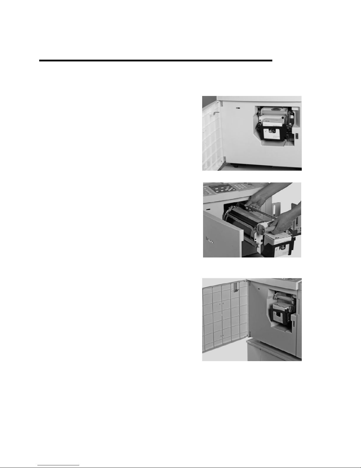
Placement of Drum
Clear errors as follows:
1. Open front cover;
2. Open drum lock switch ,take out drum;
3. Insert it again ,then press the lock switch;
4. Close front cover.
Page 78
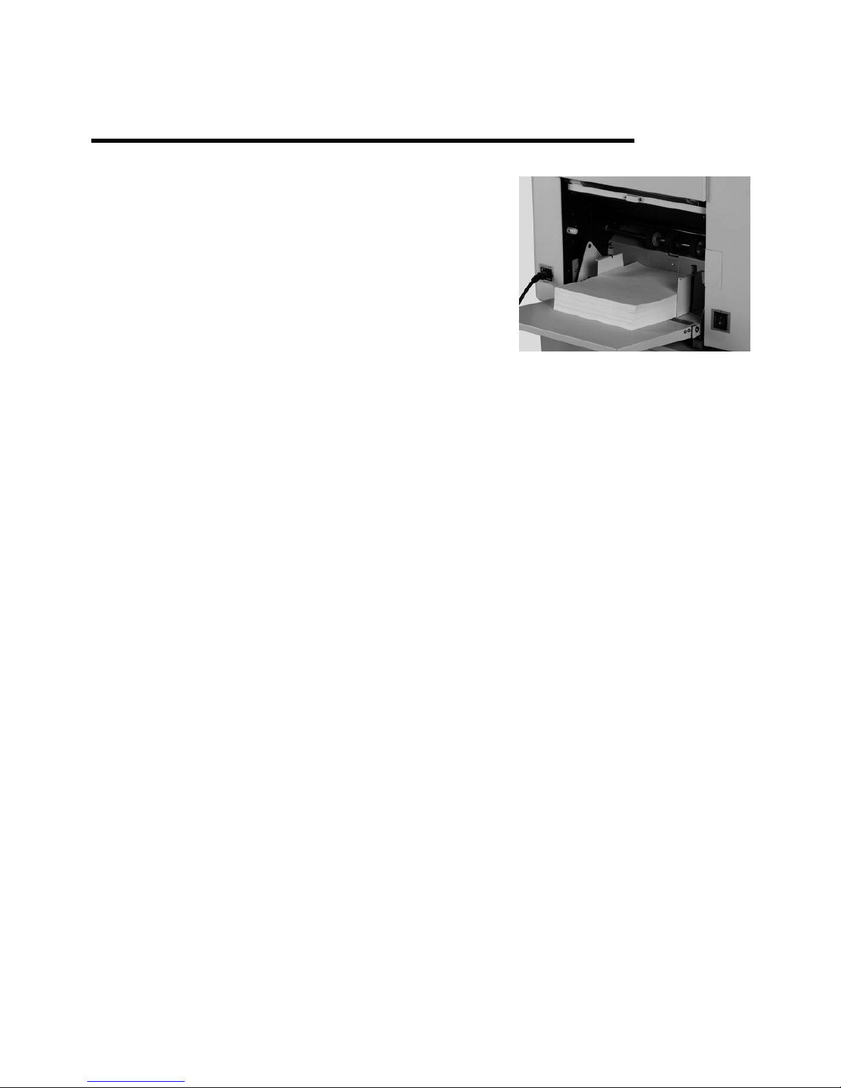
Paper Empty (for BPS 101/BPS 201)
76
Please add paper as below:
1. Place the paper onto the feed tray when feed tray elevator
stops descending;
2. Press “Start” key to stat printing , paper feed tray elevator
lifts automatically.
Page 79
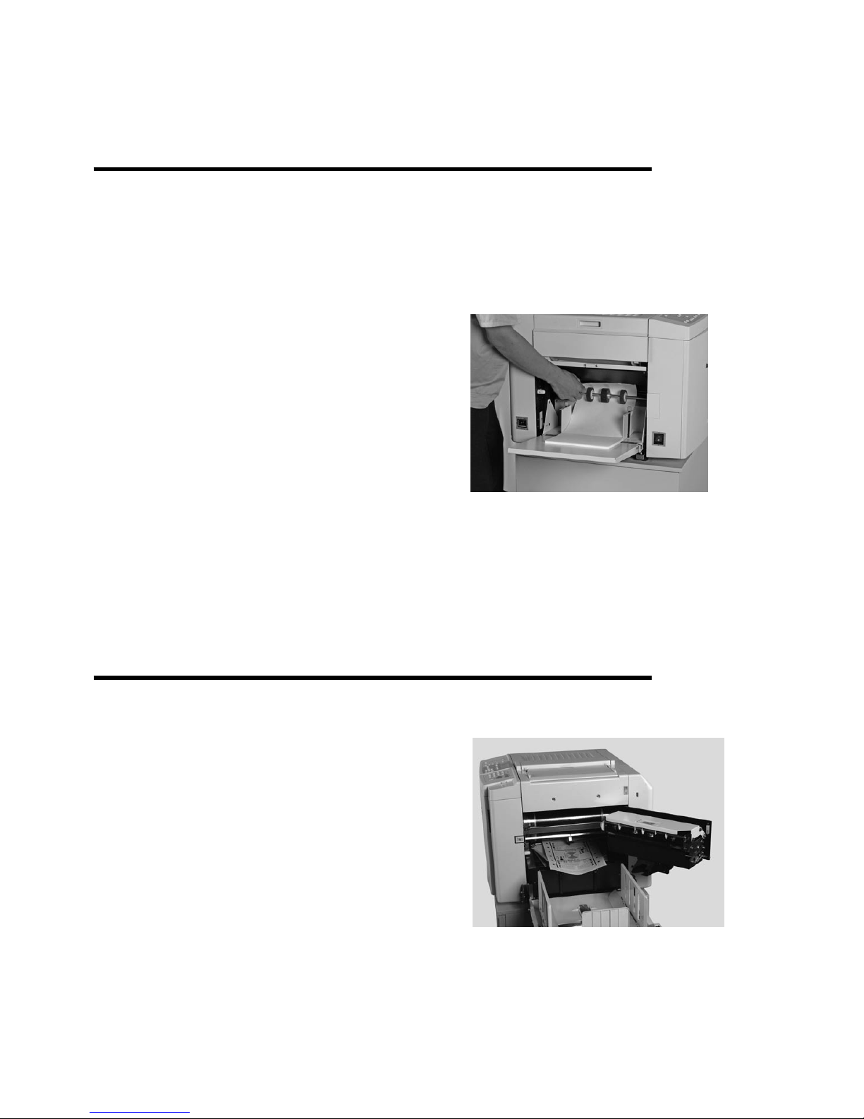
Press elevator switch and the elevator descends
Press “Start” key to print , paper feed tray lifts automatically.(BPS 101/BPS 201).
3.
)
1.
;
77
Paper Jam
Left Paper Jam
Please take out paper as below:
(
2. Take out jammed paper on the paper feed roller;
Right Paper Jam
Please take out jam paper as below:
1. Press disposal master box switch, open that box
to max;
BPS 101/BPS 201
Page 80
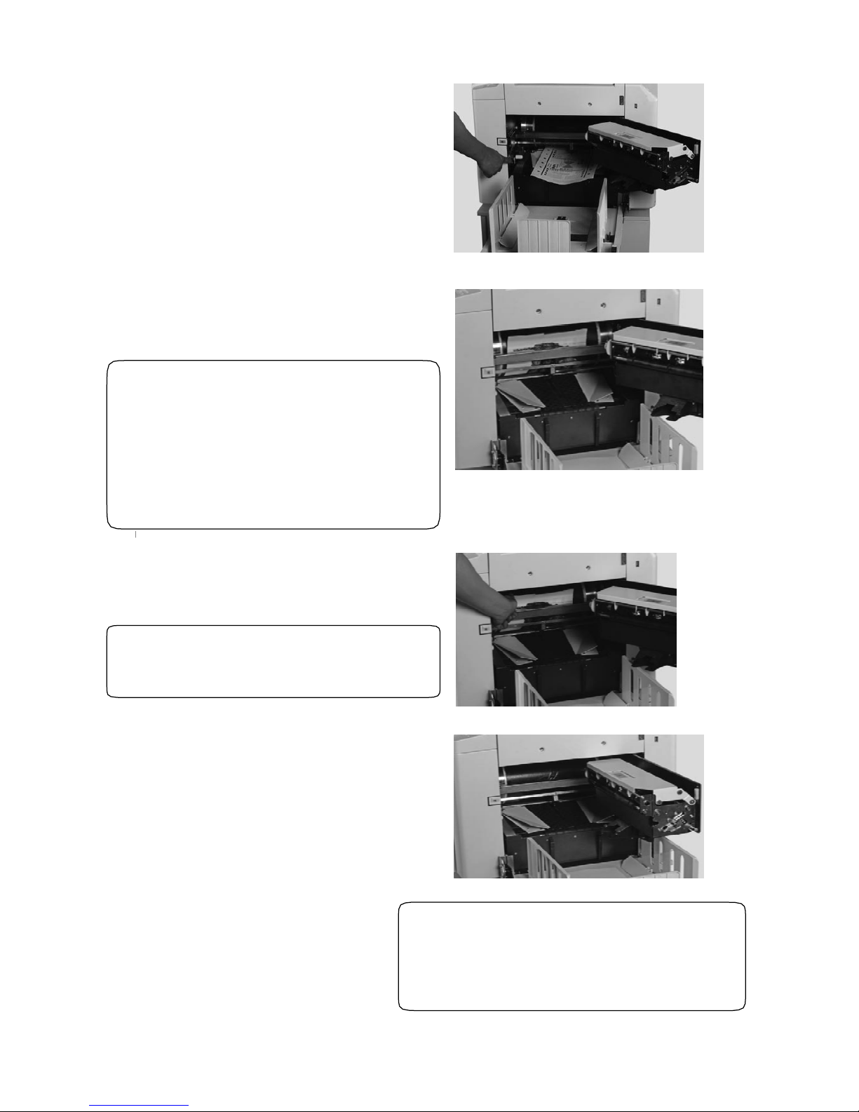
78
2. Press drum switch and take out paper jammed;
3. In case the print paper wraps onto the drum, please
press the micro switch of the drum to rotate the drum
until the head of the print paper is showed;
◆Warning:
● Please don’t touch the drum and
pressure roller when press microswitch.
● Don’t put your hand into machine
while the machine is running, avoiding
hurting.
4. Please take out that paper as press that drum
switch,remove that err;
◆Notes:
Don’t make your cloth dirty
5. Press drum switch continuously till the warning
stops. It shows drum is back to stop position;
6. Close disposal master box. ◆Notes:
In order to make quality printout, after cleaning
the warpping paper from the drum,please remake
the master.
Page 81
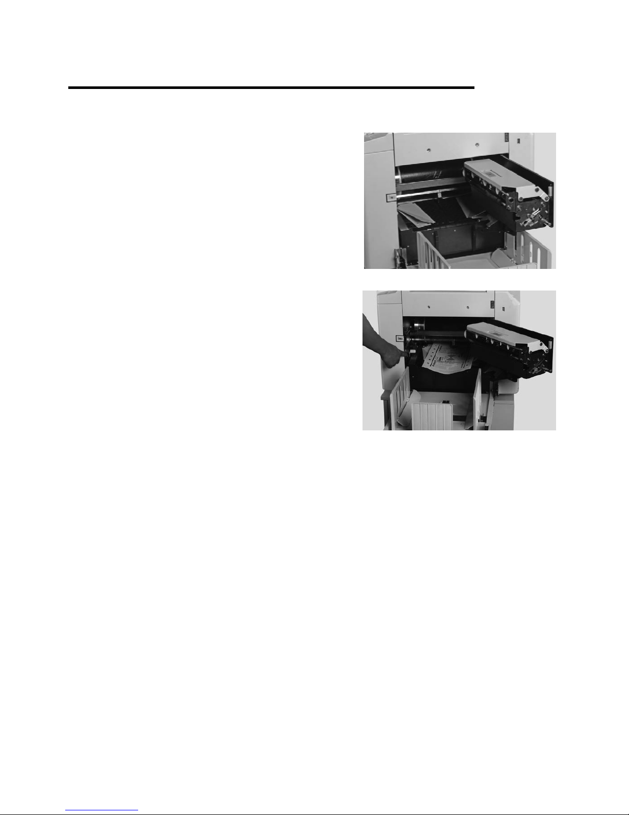
79
Middle Paper Jam
Please take out paper as below:
1. Press disposal master box switch, and open that box to
max;
2. Press drum micro switch and take out paper jammed;
3. Keep pressing drum microswith until warning stops, which indicates drum is back to stop position;
4. Close master disposal box.
Page 82
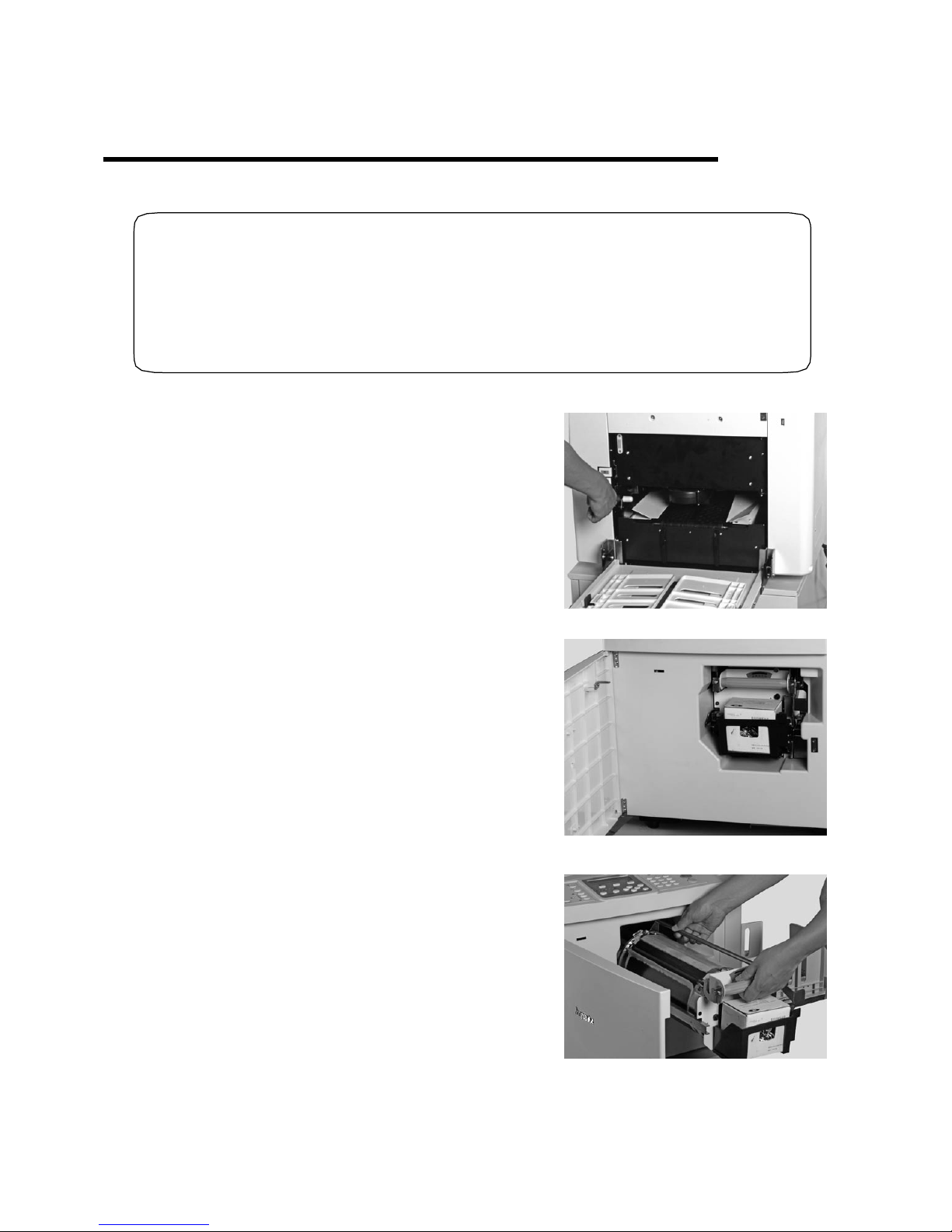
80
Master Ejection Error
Please clear error as below.
◆Warning:
● Don’t press the drum surface by hands, otherwise your hands and clothing may get
stained, moreover the drum surface may get damaged and the printout quality might be
affected.
● Be careful to locate the drum, and make sure to place it onto the level and steady flat.
1. Press drum micro switch until warning stops;
2. Open front cover;
3. Open drum locked switch ,take out the drum;
Page 83
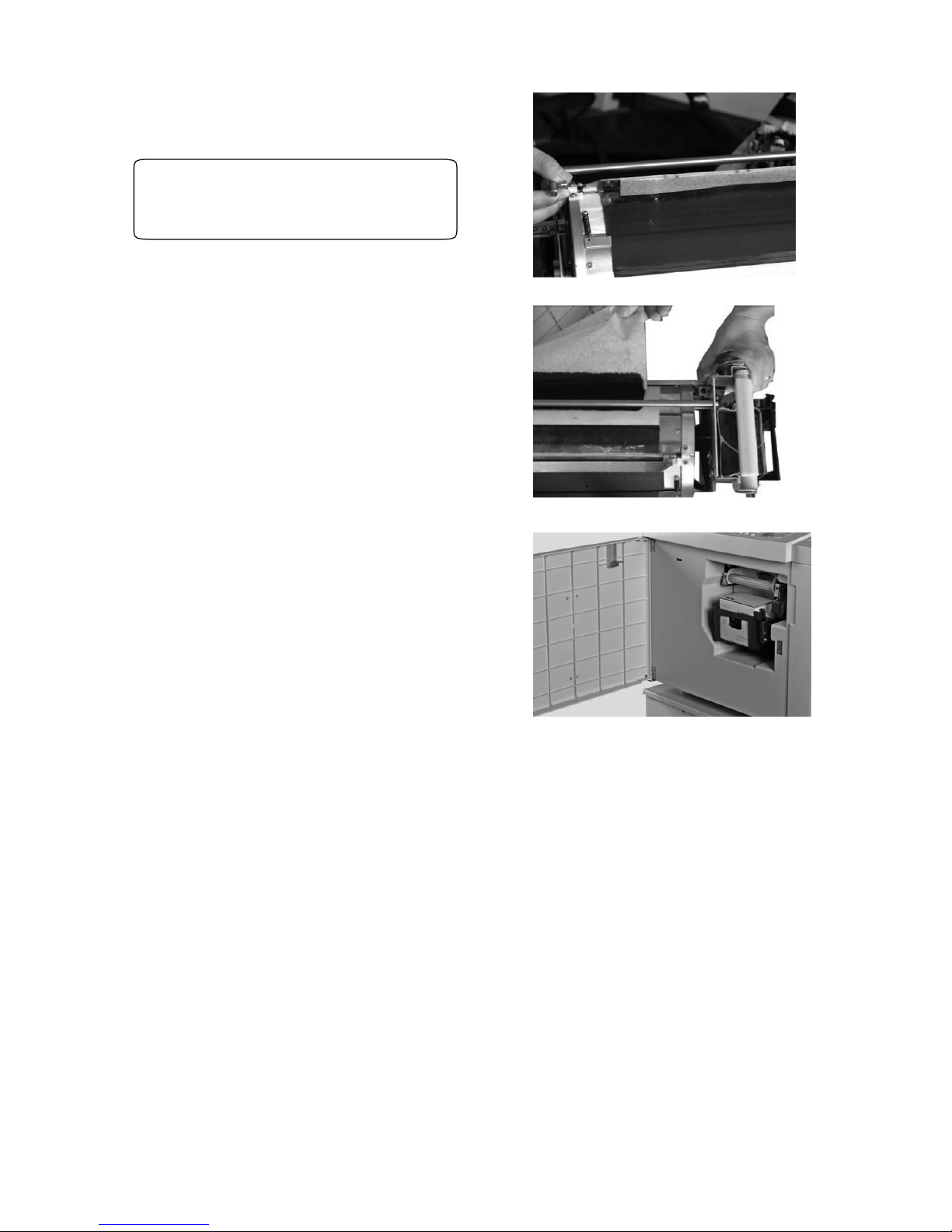
81
4. Open the clamp and release the clamp edge;
◆Notes:
Don’t make your cloth dirty
5. Clear the master manually, rotate drum to its
stop position, and make sure the block in the
groove;
6. Hold the drum flatly, insert it into the machine,
and press down the drum lock switch;
7. Close front cover;
8. Press master-making key, start again.
Page 84
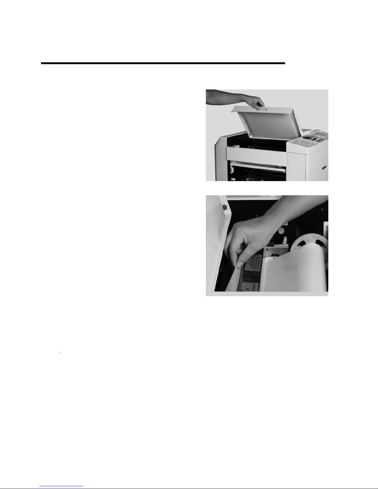
82
Master Load Error (for BPS 101)
Please clear error as below:
1. Open original paper receive tray;
2. Clear extra master;
3. Close original paper receive tray;
4. Press master-making key ,and make master again.
Page 85
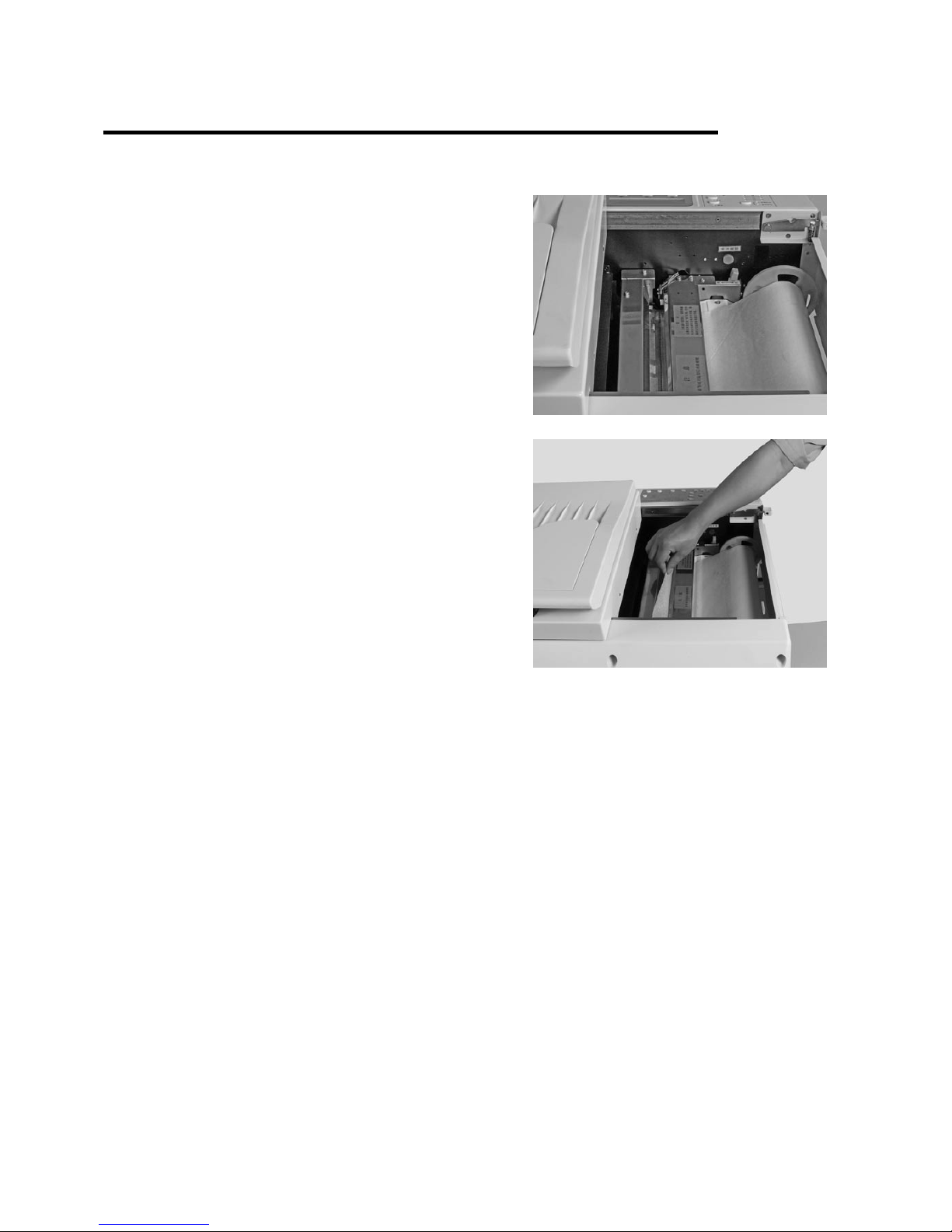
83
Master Load Error (BPS 201)
Please clear error as below:
1. Press scan lock lever, and push scan table;
2. Clear extra master;
3. Close scan table;
4. Press master-making key ,and make master again.
Page 86

84
Chapter 7
Specifications and Maintenance
Specifications———————————————————————86
Maintenance ———————————————————————87
Replace the Friction Pad ——————————————————88
Replace the Paper Switch——————————————————89
Replace/Clean the Paper Printing Roller————————————90
Replace the Soft Screen —————————————————91
Page 87
85
㎡
)
BPS 201BPS 101
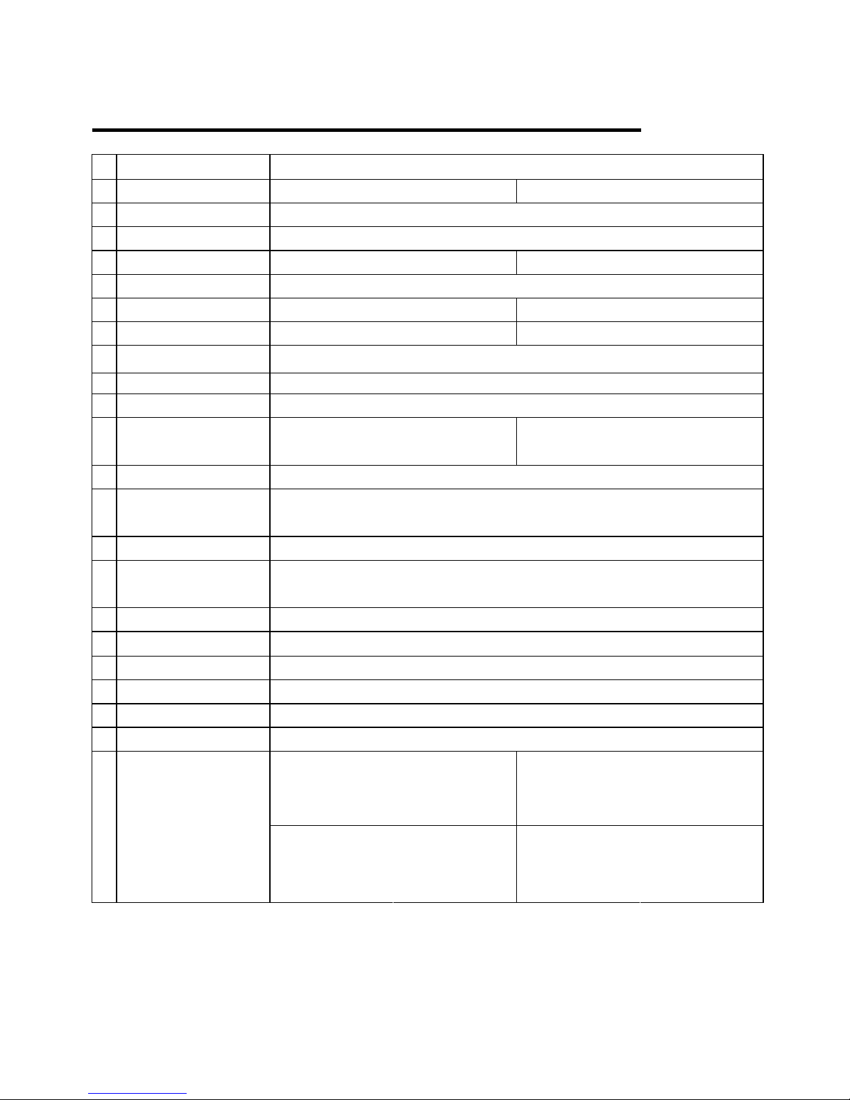
Specifications
N
o. Name Digital Duplicator
1 Model
(
B4
B4
2 Working principle Fully automatic digital scanning, thermal master making and printing
3 Processing mode Thermal master making
4 Time of first print 44S 50S
5 Resolution 300×400DPI
6 Scanning Area 252mm×355mm 285mm×406mm
7 Original size(MAX) 257mm×364mm(B4) 297mm×420mm(A3)
8 Image area(MAX) 252×355mm
9 Paper size (MAX) 297mm×420mm(A3)
10 Paper weight 40g/㎡-210g/㎡
11 Feed tray capacity
(MAX)
950sheets70g/
㎡
950sheets70g/
12 Print speed 55-120ppm(5 selections:55、70、85、105、120)
13 Regular Zoom Rate
Selection
70%、81%、87%、94%、100%(standard)、115%、122%、141%
14 Zoom Rate Selection Automatic Zoom, Free zooming:50%—2 00% at 1%
15 Print position
adjustment
±10mm
16 Original Mode Text , picture , text & picture
17 Density control Lighter, light, normal, dark, darker
18 Ink supply Automatical
19 Master load Automatical
20 Master drop Automatical
21 Master size 270mm*495mm
Pack size
747mm*707mm*
747mm
Pack size
747mm*720mm*
847mm
22
Machine size
1320mm*625mm*
Work size
510mm
1320mm*625mm*
Work size
560mm
(
)
Page 88
86
Maintenance
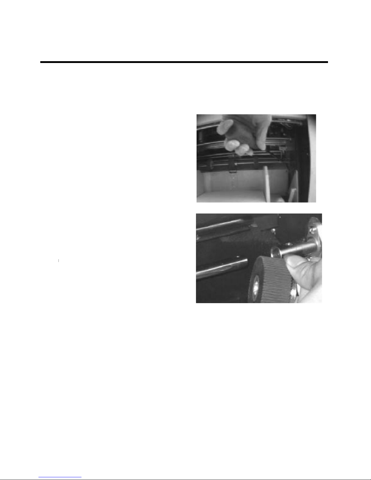
In the first paper feed section, the pressure between the paper rollers and the separator transports the
paper to second feed part. Therefore, after a number of sheets pass, the feed rollers will be worn so it
needs to be replaced.
1. Press the elevator’s microswitch and
the paper feed tray descends. Remove the
bolt on the connect knot on the right end
of the paper rollers’ shaft;
2. Move the paper rollers’ shaft until the
paper roller can be removed;
3. First remove the side rollers; take off
the screw on the main roller and then
remove the main roller. Replace with new
feed rollers and fix the screw;
4. Connect the paper roller shaft and the
connecting bolt. Make sure to fix screws.
Page 89
e
87
Replace Friction Pad
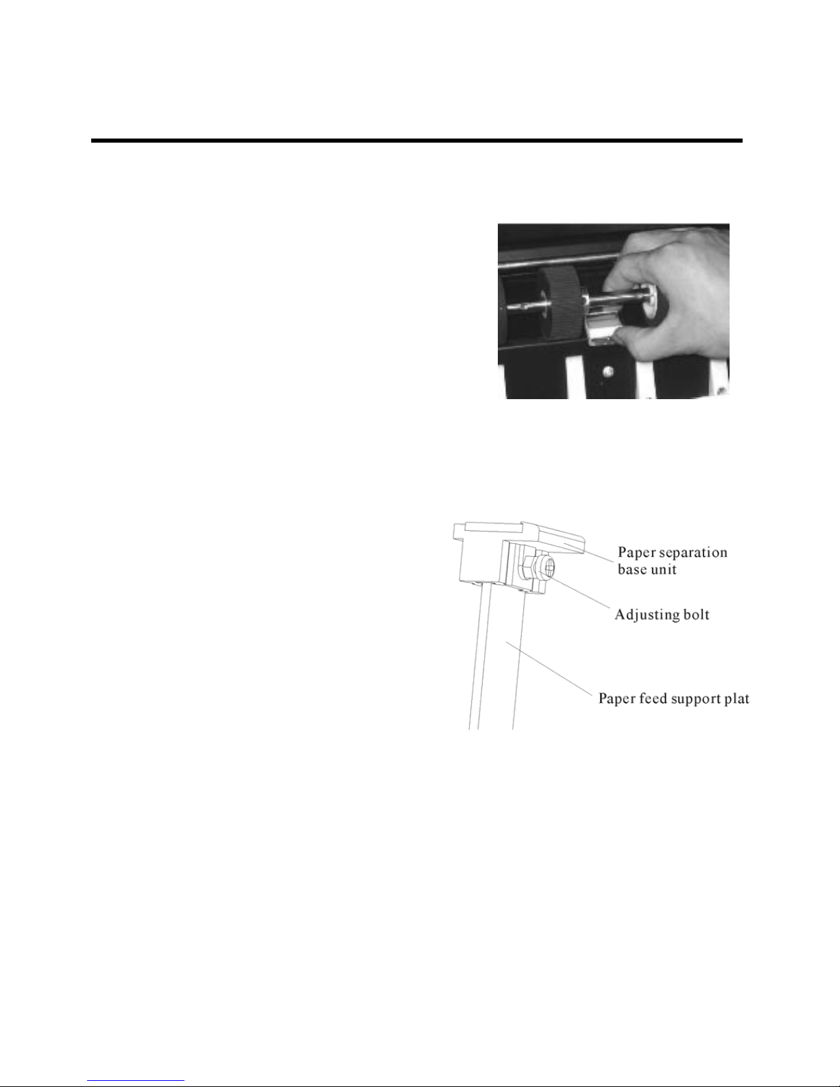
The paper sheets are separated by the pressure produced by the friction pad against the paper roller. The
friction pad will be worn after a number of sheets are fed, and it need to be replaced.
1. Press the elevator’s microswitch and
the paper feed tray descends. Remove the
bolt on the connect knot on the right end
of the paper rollers’ shaft;
2. Move the paper rollers and the shaft,
take out the old friction pad and install a
new one;
3. The clearance between the paper
separation base unit and the paper feed
support plate can be adjusted by the
adjusting bolt.
Adjustment standard. Make no clearance between
the base unit and support plate, but the support
plate can be taken out from the base unit or taken
into it by hand easily.
4. Connect the paper roller shaft to the connecting bolt. Make sure to fix the screws.
e
Page 90
88
Replace the Paper Switch
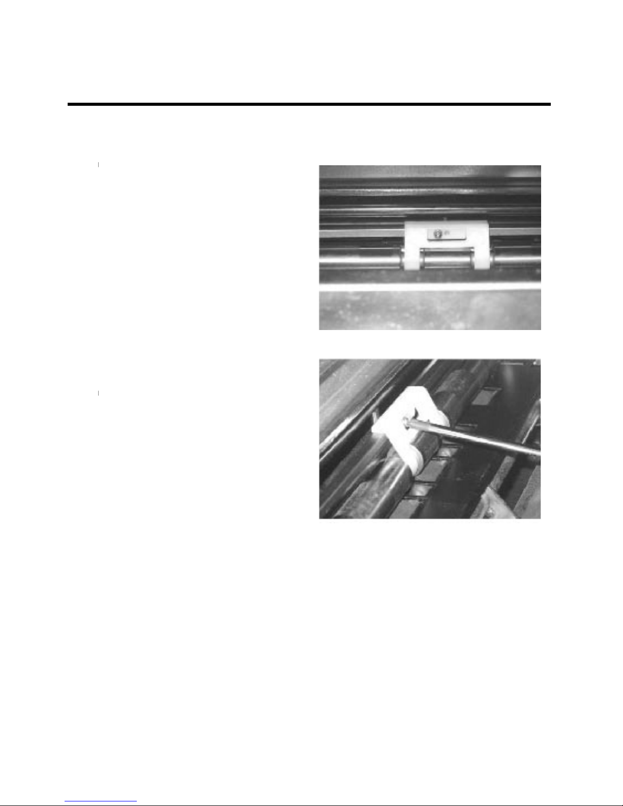
Paper switch controls the up-down movement of print roller. It is pushed open by the paper head.
It shall be worn after a number of paper printed and needs to be replaced.
1. Take out the drum, open the disposal
box and the white paper switch is
showed;
2. Disassemble the bolt on the paper
switch, and remove the paper switch;
3. Install the new paper switch, keep two
ends of switch to be parallel to the paper
plate below;
4. Close disposal box and place the drum back.
Page 91
89
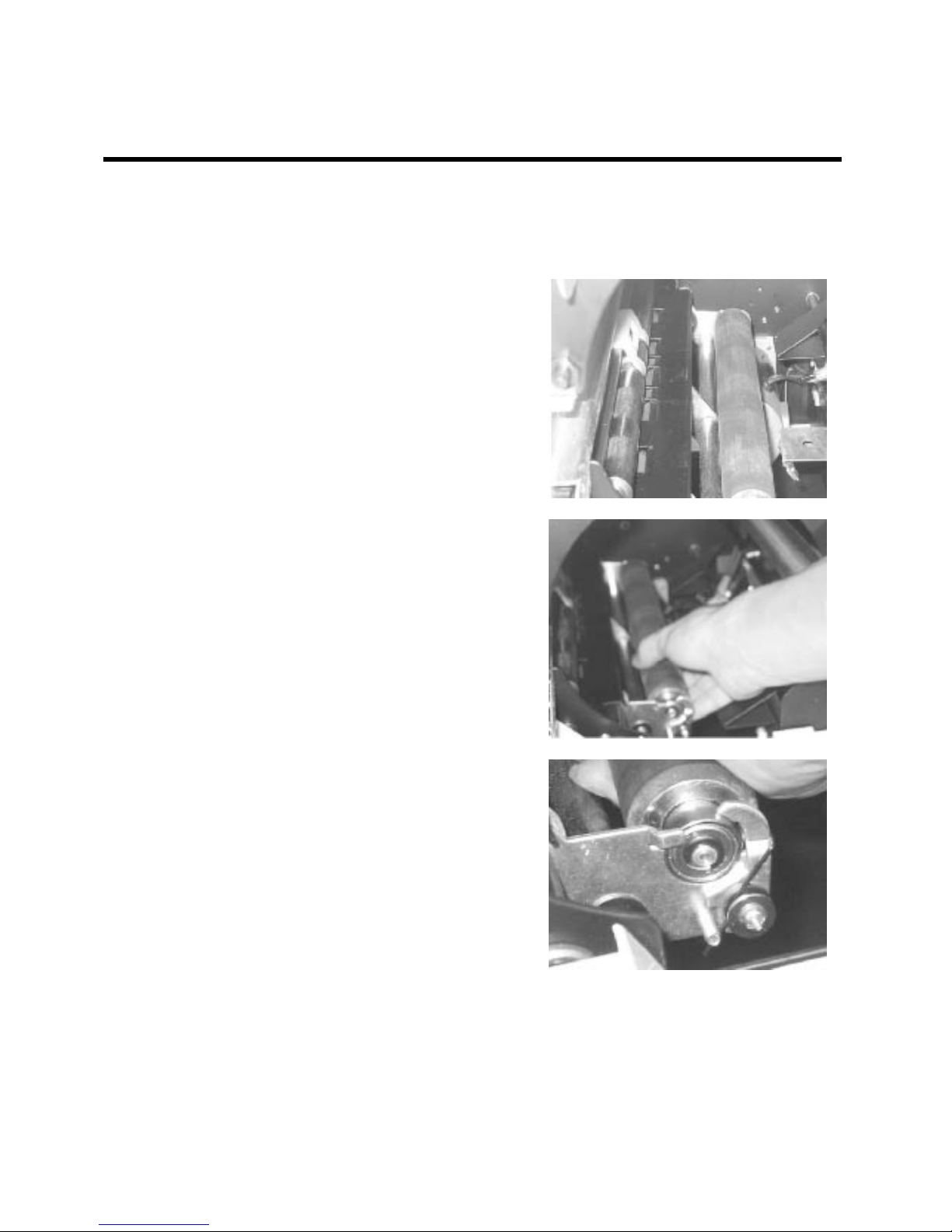
Replace/ Clean the Printing Roller
During paper is printed, the press between drum and print roller produce the pressure. Moreover, some
dust or speck comes in. In order to make sure printing is not effected, the print roller should be cleaned
or replaced when the print paper sheets reach a certain amount.
1. Open the front door, take out drum,
and you will see the print roller inside;
2. Take hold of the print roller and draw it away;
3. Clean the printing roller or replace
with a new roller.
Put one end of new print roller’s shaft
into the hole controlled by spring plate,
and then insert the o ther end in to the hole .
Put drum back and close the front door.
Page 92
90
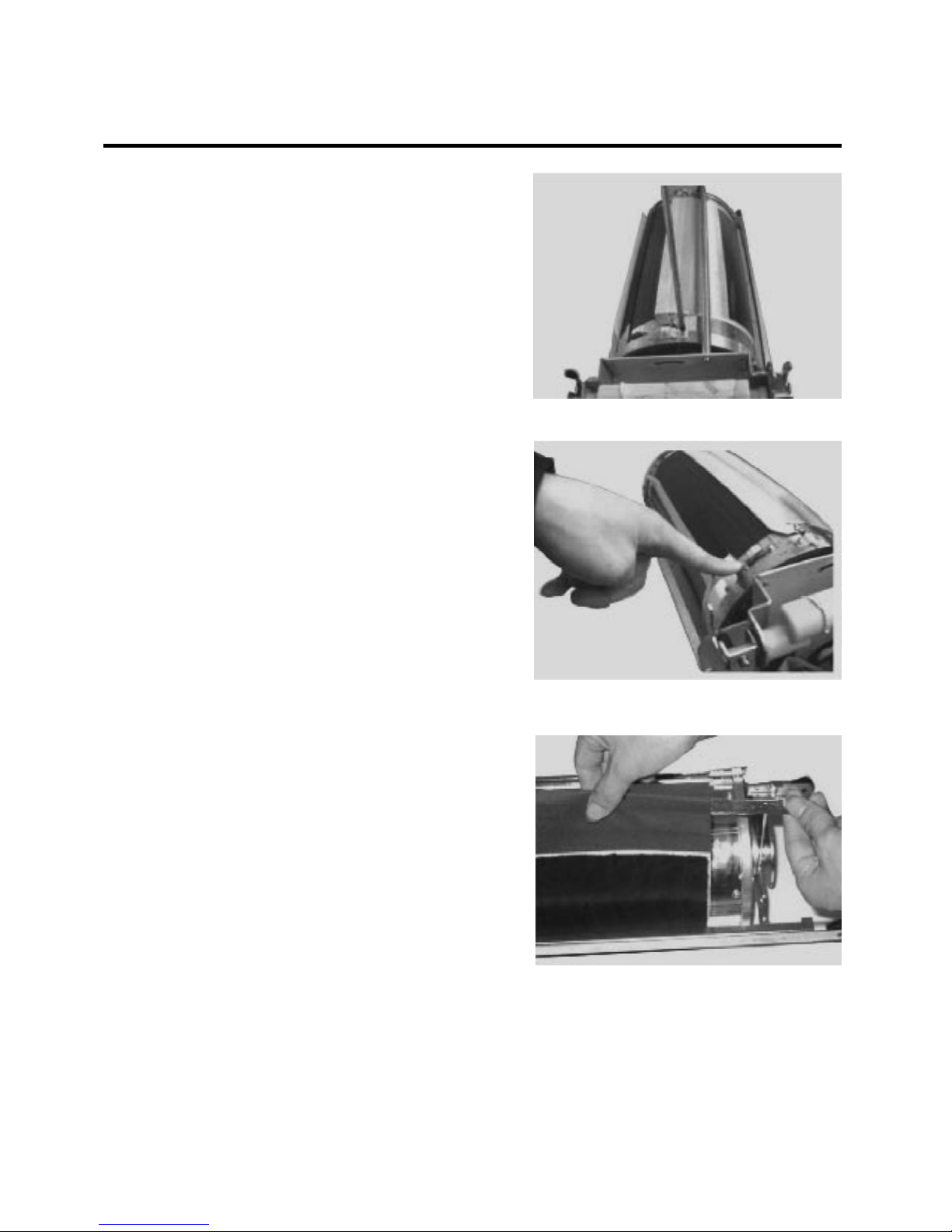
Replace the Soft Screen
1. Place drum steadily on the desktop or
floor. Discharge two press plates on the
upper frame of screen;
2. Remove lower frame of screen;
3.Take out the soft screen from the drum,
and then remove upper and lower frames
of soft screen. Insert new screen from the
front side;
4.Install new screen in reverse of the
steps of above.
Notes: The installed soft screen must be
leveled off and tightened.
 Loading...