

Page 1
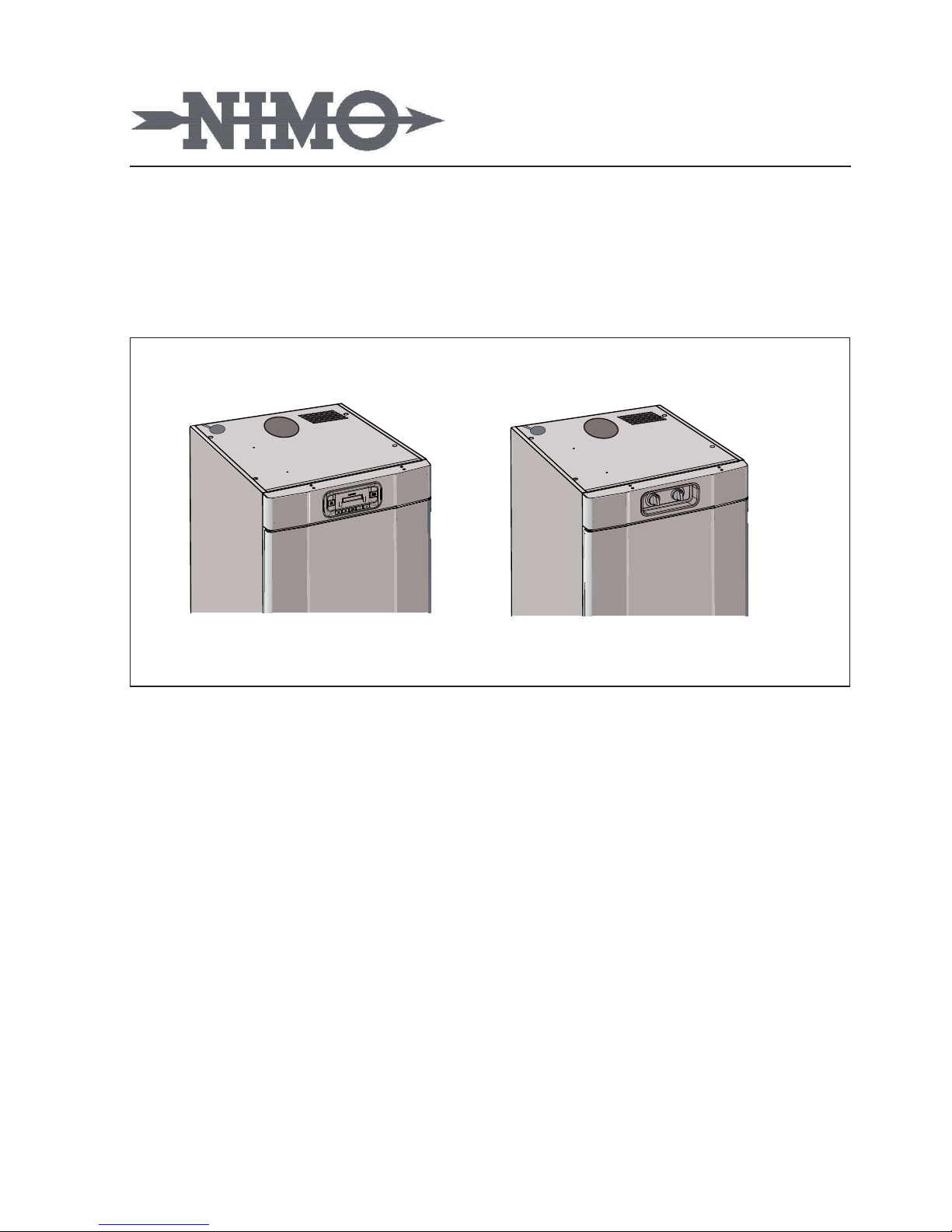
Drying Cabinet
ETS 1700E/1900E
ETS 1700 / 1900
Installation and
User Manual
ENG
Doc. No: 427000723
Keep this user manual in a safe
place, so that it will always be on
hand for future reference.
Page 2

Dear NIMO customer,
Congratulations on making an excellent choice and welcome to the
NIMO family. NIMO is a global family with its roots in Sweden.
NIMO thanks you for your condence and hopes that you will enjoy
using your new drying cabinet.
A good drying cabinet should be well designed, dry clothes well, have a
low environmental impact, be user friendly, save time, have a long life
and be reliable. NIMO offers you all of these features.
When you buy a NIMO product you can be sure that the inside is as
good as the outside and that the ethics and morality that go into buil-
ding this product are just as high as the quality and functionality you
are getting. That’s what Swedish quality is all about.
Before using the product for the rst time, please read the user instruc-
tions and the advice on caring for the product. This will help you get the
best possible results from your product and all its functions.
If you have any questions, don’t hesitate to call us or contact us via our
website.
Best wishes from Sweden and the NIMO team.
Doc. No: 427000723 Rev. 03
Manufacturer: NIMO-VERKEN AB Box124
S-548 22 HOVA
Sweden
Ph +46 (0) 506 488 00
Fax +46 (0) 506 488 10
[email protected]
www.nimoverken.com
ARTICLE AND SERIAL NUMBER
See page 23
Page 3

3
CONTENTS
ABOUT THIS USER MANUAL 4
SAFE USE 5
USES 5
TECHNICAL SAFETY 5
FOR A GOOD ENVIRONMENT 6
PACKAGING MATERIAL 6
MANAGEMENT OF ENDOFLIFE
DRYING CABINET 6
DESCRIPTION OF THE DRYING CABINET
7
INSTALLATION 8
UNPACKING 8
FITTING THE DOOR HANDLE 9
REHANGING THE DOOR 9
POSITIONING / FIXING THE CABINET
12
EXHAUST / SUPPLY AIR 13
EXHAUST CONNECTION 13
ELECTRICAL CONNECTIONS 15
USING FOR THE FIRST TIME 16
POSITIONING THE WASHING 17
USER TIPS 17
AIRFLOW 17
USING THE ETS 1700E / ETS 1900E
DRYING CABINET 18
CONTROL PANEL 18
DISPLAY 18
DRYING PROGRAMME 19
DRYING FUNCTION 19
BREAKDOWNS 21
AUTOMATIC PROGRAMMES
SETTING THE PARAMETERS 21
USING THE ETS 1700 / 1900
DRYING CABINET 22
SETTINGS 22
CARE 23
CLEANING 23
SERVICE 23
TECHNICAL DATA ETS 1700E / 1900E 24
TECHNICAL DATA ETS 1700 / 1900 25
PARAMETER ADJUSTMENT ETS 1700E /
1900E 26
INTRODUCTION 26
PARAMETER ADJUSTMENT 27
Page 4

4
ABOUT THIS USER MANUAL
The contents of this user manual describe the drying cabinet’s functions
and how it should be used. The manual
also includes instructions for installation and maintenance.
Page 5

5
SAFE USE
This advice on safe use is intended to enable you to avoid incorrect use and to reduce
the risk of unnecessary accidents, and should be read prior to installation and use
of the drying cabinet.
USES
CAUTION! This equipment is only in-
tended to be used to dry fabrics washed
in water.
The drying cabinet can be used by
children aged 8 or over and persons (including children) with physical, sensory
or mental impairments, provided they
have received guidance or information
on how to use the drying cabinet safely
and understand the risks that can occur.
Do not allow children to play in or on the
drying cabinet. Keep an eye on children
when they are in the immediate vicinity
of the cabinet.
Cleaning and maintenance must not be
carried out by children without supervision.
TECHNICAL SAFETY
Check the drying cabinet for visible
damage before installing it. A damaged
drying cabinet must not be used as it may
pose a hazard.
The drying cabinet must only be con-
nected to a grounded socket installed
in accordance with applicable safety
regulations. After installation the wall
socket must be accessible so that the
power supply to the drying cabinet can
be disconnected at any time.
Check that the data on the drying cabi-
net’s data plate (fuse, voltage and frequency) is in agreement with the mains
supply at the place where the cabinet is
installed.
The drying cabinet must not be con-
nected using an extension cable as the
necessary safety cannot be guaranteed
(risk of overheating).
If the mains lead is damaged it must
be immediately replaced, and only by
the manufacturer, the manufacturer’s
service agent or similar qualied persons
to avoid danger.
This drying cabinet meets applicable safety requirements. Incorrect use may, however,
lead to injuries and damage to property.
Page 6
6
FOR A GOOD ENVIRONMENT
PACKAGING MATERIAL
The packaging that protects the drying cabinet against damage in transit
has been chosen with concern for the
environment in mind and is therefore
recyclable.
Recycled packaging means reduced
consumption of raw materials and lower
levels of waste.
MANAGEMENT OF ENDOFLIFE
DRYING CABINET
When the drying cabinet has reached
the end of its life, it must be taken to
a recycling centre for disposal. Many
parts can be re-used, but the cabinet
also contains other material that must
be handled correctly. You should therefore never dispose of a drying cabinet
or parts of a cabinet with the domestic
refuse as this can lead to health risks and
harm the environment.
Take the end-of-life drying cabinet to
a recycling station instead. Check with
your dealer if necessary.
All the plastic parts of the drying cabinet
are marked with internationally standardised symbols. The parts can therefore be recycled in an environmentally
friendly way by waste separation.
Page 7
7
DESCRIPTION OF THE DRYING CABINET
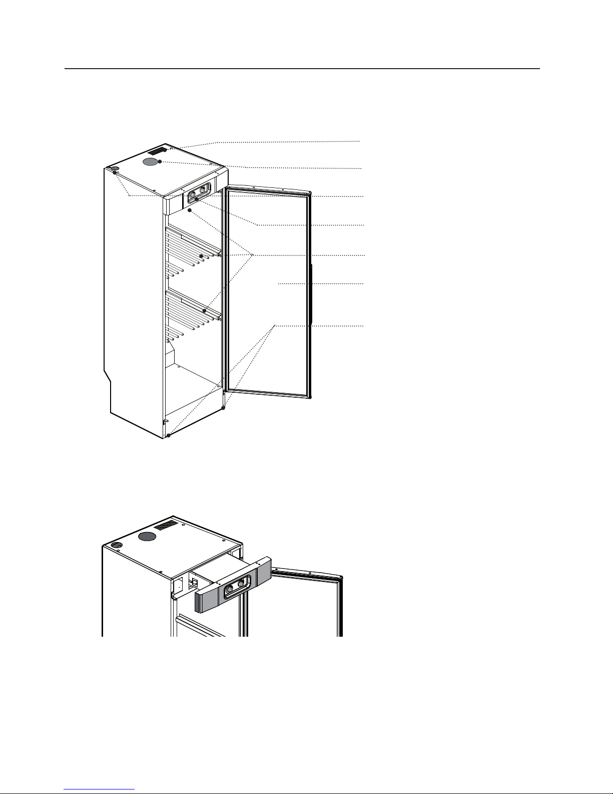
Air intake
Moist air out
Hole for connecting cable
Control panel
Three expandable hangers
Door, can be changed to open
from the left or the right
Adjustable feet (4x)
Service module
The heating and fan components
are combined in a removable
service module.
Figure shows the
ETS 1700/1900
drying cabinet
Page 8
8
UNPACKING
INSTALLATION
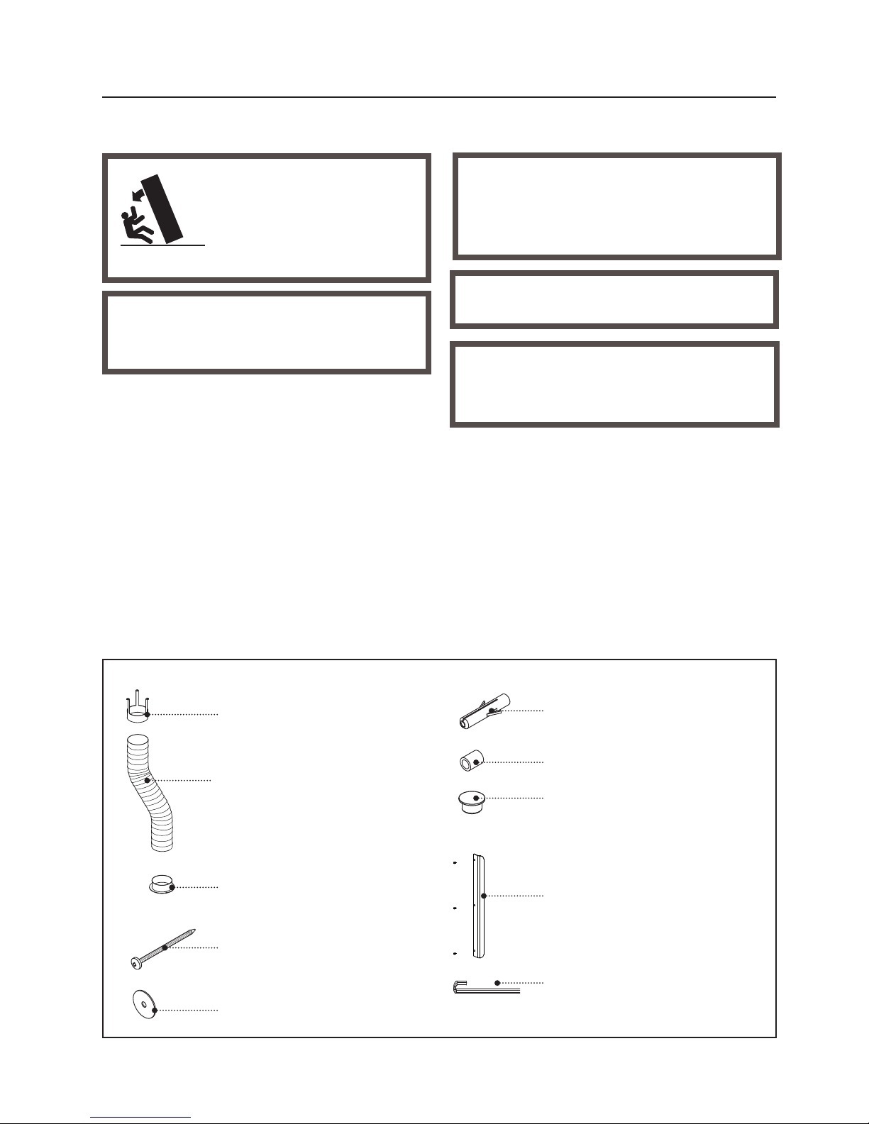
Qty.
Draught stabiliser 1
Hose 1
Sleeve 1
Screw TRX 5x70 fzk 2
Washer NB 5x25 2
Assembly kit:
Complete delivery should include:
A cabinet with a fan unit installed
Assembly kit
Installation anf User Manual
Packaging materials such as plastic and
styrofoam should be kept out of the reach
of children.
Check that all transportation aids have
been removed before connecting the dryer.
After unpacking, check that the goods are
in good condition. Damage, faults and
any missing parts should be immediately
reported to your dealer.
Check that the goods have not been
damaged in transit. Any damage should
be reported to your dealer within 7 days.
The drying cabinet should
be handled carefully if it is
only standing on its wooden
pallet. RISK OF TIPPING
OVER
Qty.
Nylon plug 2
Spacer 8.2x12x15 2
Cover plug, white 4
Door handle with
xing screws 1
Aller wrench 1
Page 9
-
+
START
STOPP
MAN
60°
40°
-
+
MAN 4
0
° 2:30
C
START
STOPP
ON
OFF
ECO DRYER
2
1
9
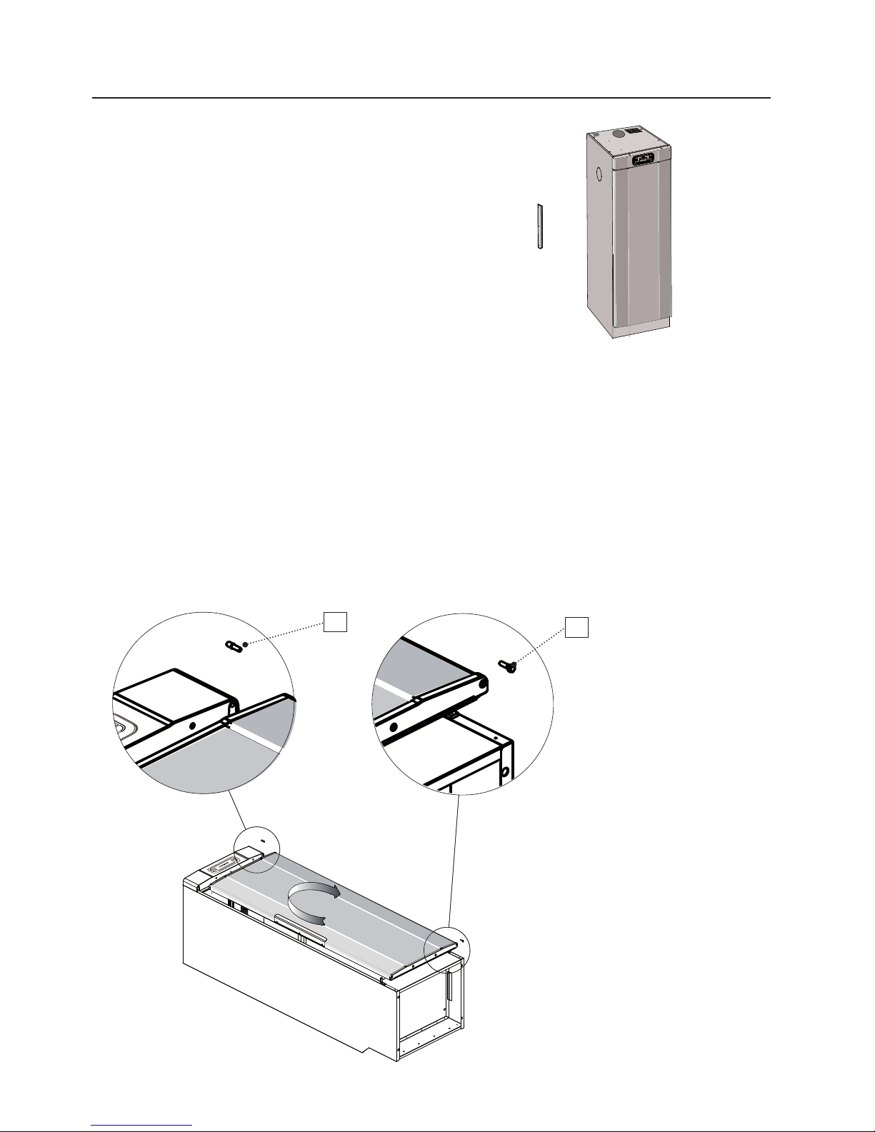
REHANGING THE DOOR
The door can be hung on the right or to the left.
FITTING THE DOOR HANDLE
Fit the door handle with the fixing
screws supplied.
INSTALLATION
1 Lay the drying cabinet on its back.
2 Undo the hinge pin from the bottom
hinge (1) and lift o the door.
3 Undo the plastic plug and insert it in
the opposite-side lower hinge.
A LOWER HINGES ARE PRE-MOUNTED ON BOTH SIDES
4 Undo the hinge pin from the top
hinge (2) and place it on the opposite
side.
5 Rotate the door, align and secure the
door with the lower hinge pin (1).
Page 10
MAN
60°
40°
-
+
MAN 4
0
° 2:30
C
START
STOPP
ON
OFF
ECO DRYER
3
4
10
INSTALLATION
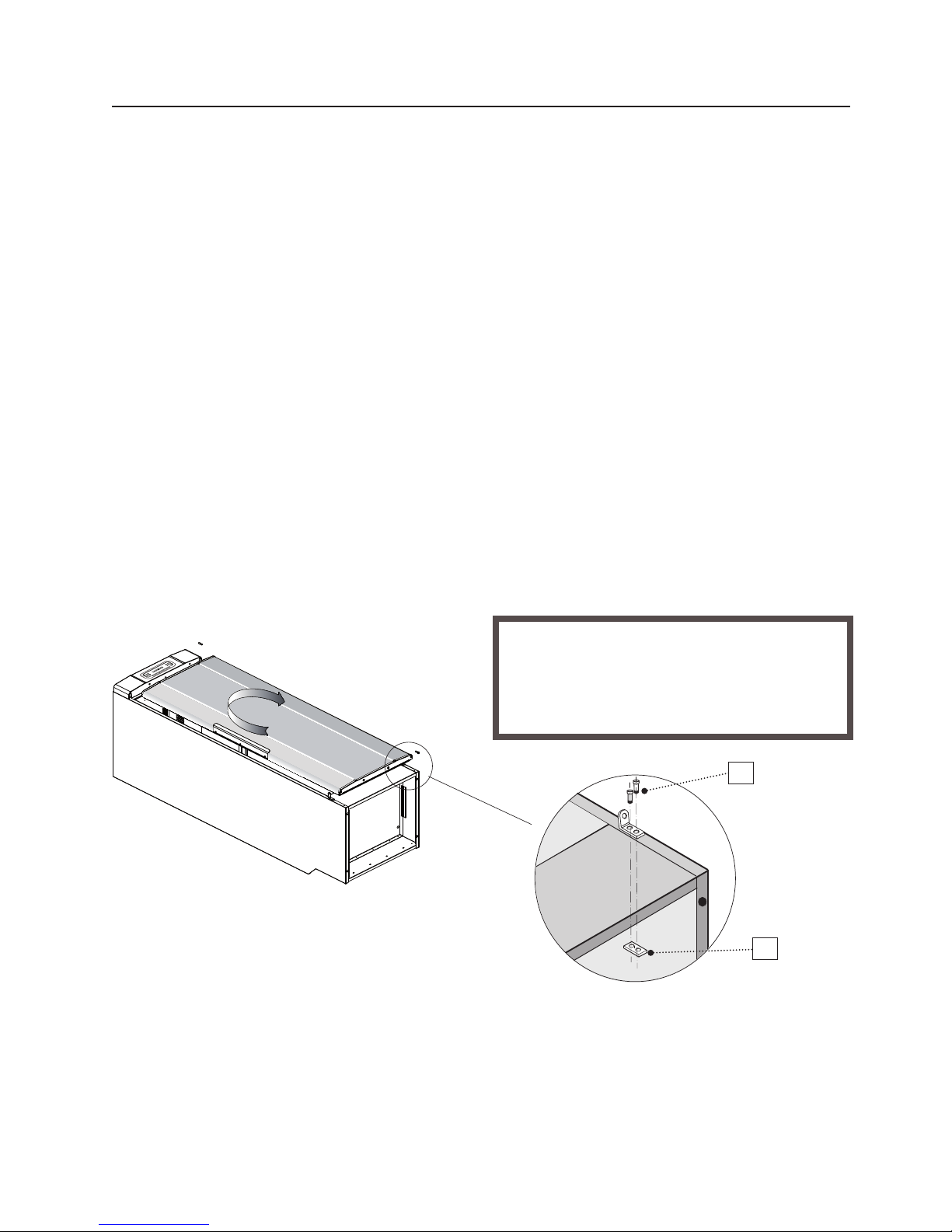
Some models do not have a lower hinge
mounted on both sides. In this case the
existing hinges must be moved to the
required side. The hinge is attached
with two screws and threaded washers
as illustrated.
Note that the washer is not attached to
the cabinet frame.
B NO LOWER HINGE ON THE OPPOSITE SIDE
Rehanging the door when the appliance is resting on its back
1 Undo the hinge screws (3).
2 Screw the threaded washer back on
(4). On the opposite side there is a th-
readed washer already pre-mounted.
3 Mount the hinge in its new position.
4 Undo the hinge pin from the top
hinge (2) and place it on the opposite
side.
5 Rotate the door, align and secure the
door with the lower hinge pin (1).
After the hinge has been mounted on the
opposite side, threaded washers must
be refitted in their former position. This
increases the stability of the cabinet.
Page 11

11
The door can also be rehung when the
cabinet is already bolted to the wall and
thus cannot be laid on its back.
1 Undo the lower hinge pin (1) from
the bottom hinge and lift off the
door. The pin is fastened using a No.
10 sized key.
2 Undo and unscrew the upper of the
two hinge screws (3) and loosen the
lower one a little. Rotate the hinge to
the side. Ret the upper screw.
3 Undo the lower mounting screw and
remove the hinge. Ret the screw.
4 Mount the hinge in its new position
in reverse order, i.e. start by securing
the hinge with the lower screw. This
prevents the threaded washer from
becoming loose which could make
it dicult to access the inside of the
base.
5 Undo the hinge pin from the top
hinge (2) and place it on the opposite
side.
6 Rotate the door, align and secure the
door with the lower hinge pin (1).
Rehanging the door when the cabinet is xed to the wall
INSTALLATION
Page 12
TS 560-E
MAN
60°
40°
+
MAN 40° 2:30
C
START
STOPP
ON
OFF
ECO DRYER
4
3
6
5
2
1
7
8
9
12
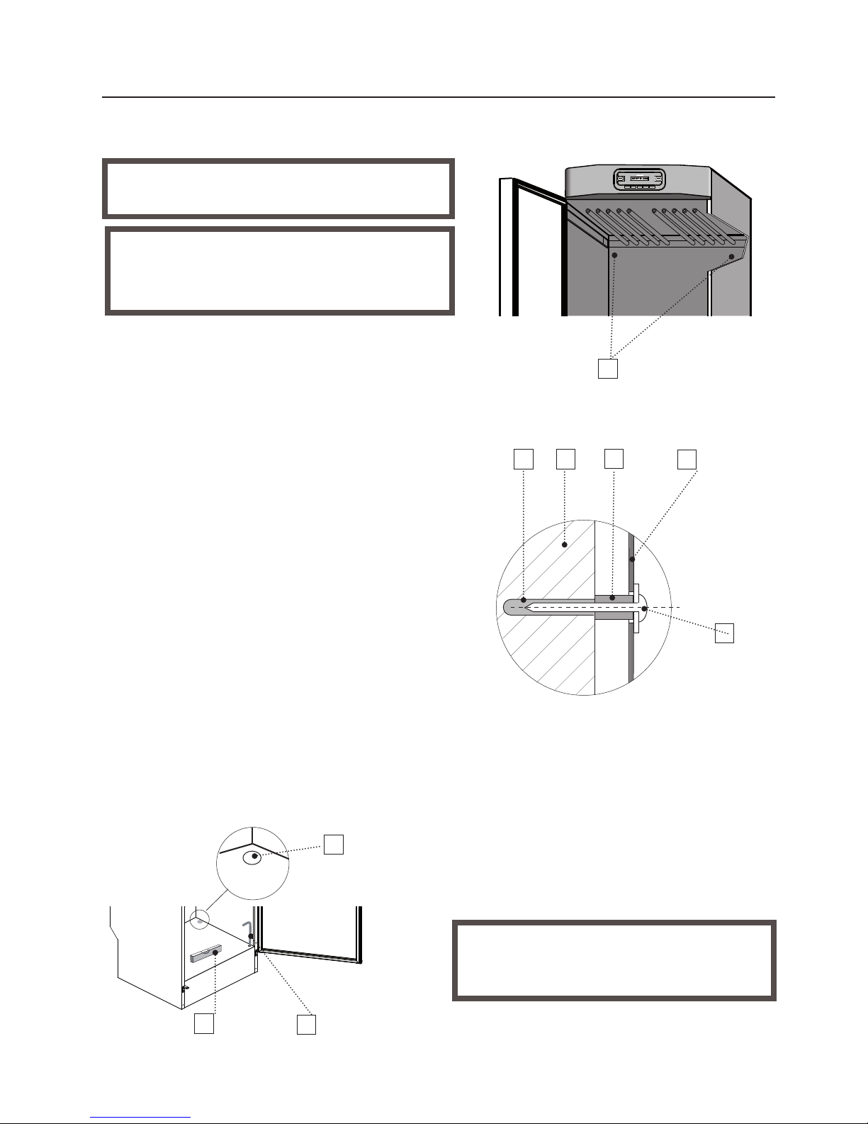
1. Pre-drilled holes
2. Attachment screw with washer
3. Plastic plug
4. Wall behind the drying cabinet
5. Spacer
6. Drying cabinet back wall
7. Spirit level
8. Allen wrench
9. Cover plug
The drying cabinet should stand level on
a at surface and rest on all four feet.
Use the Allen wrench provided, and
correct the position of all four adjustable
feet through the holes in the base plate of
the drying cabinet.
Press the four cover plugs down rmly
into the holes.
The drying cabinet must be screwed to
the wall to prevent tipping.
1 Open the front door and drill 8 mm
holes in the wall through the two predrilled holes in the rear of the drying
cabinet.
2
Insert plastic plugs into the holes in the
wall. Thread the spacer onto the screw
and install with a washer as shown in
the illustration. Screws are supplied in
the assembly kit.
WARNING The drying cabinet should not
be used without being screwed to the wall
due to risk of tipping forwards.
POSITIONING / FIXING THE CABINET
INSTALLATION
The drying cabinet is only designed for
operation indoors in a dry environment .
The drying cabinet should not be installed in a
location where high pressure water is used for
cleaning.
Figure shows the
ETS 1700E/1900E
drying cabinet
Page 13
1
2
3
13
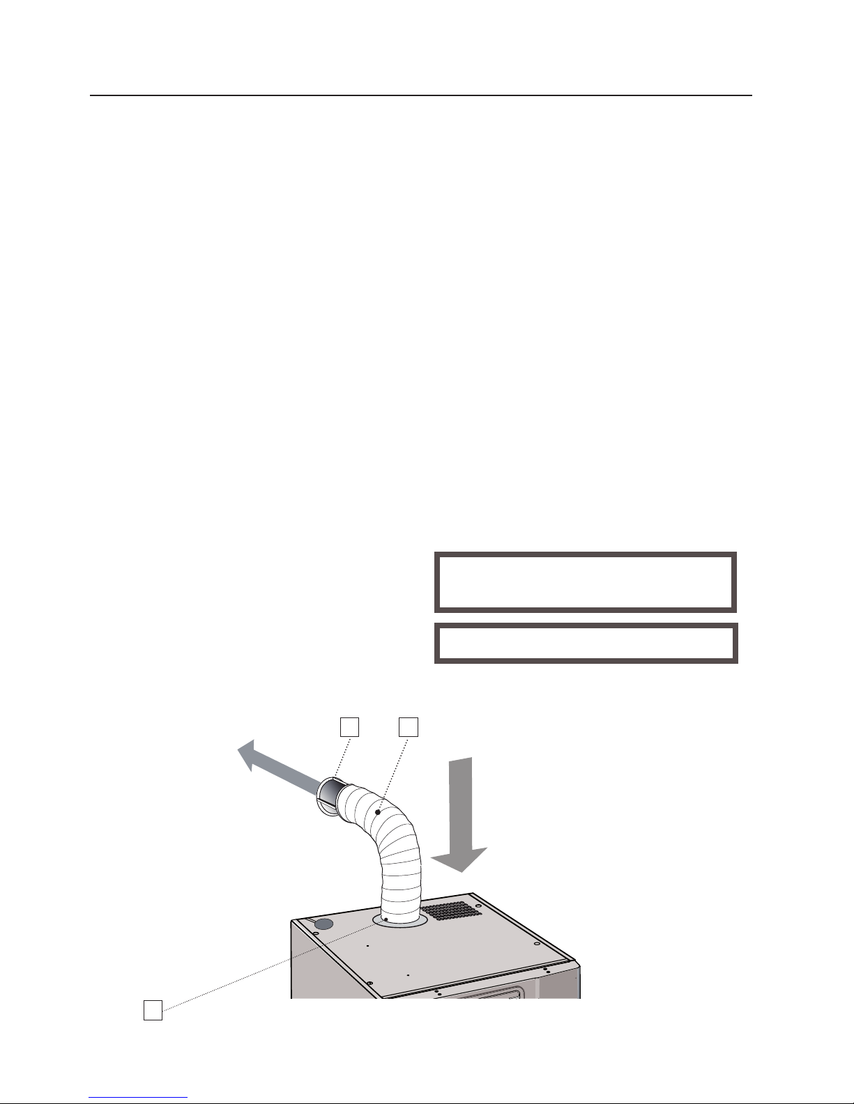
Air intake
The air intake must not be blocked.
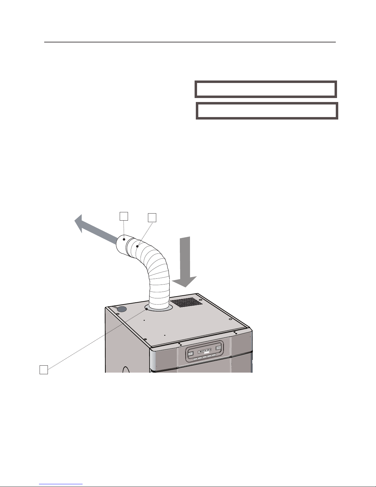
1. Draught stabilizer
2. Hose
3. Sleeve
EXHAUST CONNECTION
The drying cabinet must not be
connected to a fireplace duct.
Fit the sleeve supplied to the hose.
Ax the sleeve and hose to the
dryer top.
Connect the other end of the hose
to the draught stabilizer which
should then be rmly attached to
the exhaust valve in the room.
EXHAUST / SUPPLY AIR
When the drying cabinet is working, about 45 m³ of moist is are evacuated
per hour. This air is taken from the room where the dryer is sited. Hence make
sure air can enter the room to replace the moist air leaving.
1. By means of a draught stabilizer
The drying cabinet should be connected to a standard exhaust air ventilation system.
The drying cabinet can be connected to an exhaust duct in two ways: either with a
draught stabilizer or rigidly connected to a mechnical exhaust air ventilation system.
If the drying cabinet is to be connected to an existing ventilation system, a draught
stabilizer must always be used, so that the general ventilation in the room is not aected.
Only use a rigid connection when a separate exhaust air duct has been provided for
the drying cabinet. The air ow in the exhaust duct should be adjusted to 45 m³/hour.
The drying cabinet has been tested and set at the factory for connection with a
draught stabilizer.
Moist air out
INSTALLATION
Page 14
1
2
3
3
MAN
60°
40°
-
+
MAN 4
0
° 2:30
C
START
STOPP
ON
OFF
ECO DRYER
14
2. Permanently installed and connected to a mechanical exhaust air
ventilation system
When the drying cabinet is permanently
connected to the evacuation duct, the
whole room is ventilated by way of the
drying cabinet.
Fit the sleeve supplied to the hose.
Ax the sleeve and hose to the dryer
top.
The insert is not supplied.
Air intake
The air intake must not be blocked.
1. Insert
2. Hose
3. Sleeve
Moist air out
INSTALLATION
Page 15
15
The drying cabinet should be connected to a 230 V single-phase 50 - 60 Hz
grounded socket.
The drying cabinet is supplied ready for
connection with a cable with a grounded plug.
ELECTRICAL CONNECTIONS
The manufacturer cannot be held liable if
the electrical connections are not carried
out as prescribed in this manual.
Check that the supply current matches
that stated on the identification plate and
that the mains lead is grounded correctly
according to standards in force. We
recommend that the mains lead be fitted
with a residual current device (RCD).
Appliance must be connected to a
dedicated circuit.
The socket should be located where the
plug can be easily disconnected when
required.
The drying cabinet should be connected
using the plug supplied to a grounded wall
socket, and should not be permanently
connected.
INSTALLATION
If the power cable is damaged in any
way, it must be replaced. Genuine replacement power cables are available
from your dealer.
NOTE Replacement power cables
should only be replaced by a
qualied electrician!
Page 16

16
1 Check that the cabinet is rmly se-
cured to the wall. See page 12.
2 Check that no packaging material has
been left in place.
3 Use a mild detergent and warm water
to wash the inside and outside of the
drying cabinet. Dry carefully. See also
the section headed ’Care’ later in the
manual.
USING FOR THE FIRST TIME
Read these directions for
use before using the drying
cabinet for the rst time.
CAUTION! Read the safety instructions on page 5 before using the cabinet.
Page 17
MAN
60°
40°
+
MAN 40° 2:30
C
START
STOPP
ON
OFF
ECO DRYER
17
POSITIONING THE WASHING
In the cabinet there are three sections with hangers. Every section has a
number of bars on which to hang the
washing.
The optimised hanging system has extendable hangers.
Hang the articles in the drying cabinet
according to how much room they
require - not according to their weight.
For optimum eciency - do not lay articles at on the upper hanging section.
Long clothes nearest to the walls of
the cabinet and shorter ones towards
the centre. By hanging the washing
in this way the most ecient drying
results are attained.
Turn up the two lower hanging sec-
tions if long clothes are to be dried.
Hang gloves, caps, scarves and suchlike on
the hanger strips on the inside of the door.
Pull the upper hanging hooks for-
ward in order to hang the washing
more easily. Return when not in use.
Do not overload the drying cabinet.
If you do, the washing will become
creased and dry uneven. Instead, leave
a certain distance between items of
washing, if this is possible
To avoid transfer of colours, make sure
materials do not contact each other.
Avoid drying heavy garments at the
same time as lighter items as they
hold more moisture and have completely dierent drying times.
USER TIPS
Always follow the washing instruc-
tions on garments if such instructions
are provided.
If fabric softener or antistatic product
is used, the manufacturer’s instructions concerning the utilisation of
the product should be followed.
Take out washing that is already
dry. This reduces drying time for the
washing that is left.
NOTE When the cabinet is cold, it can
happen that the sealing strip in the door
does not close completely. However, this
is fully compensated when the cabinet
warms up as the sealing strip expands.
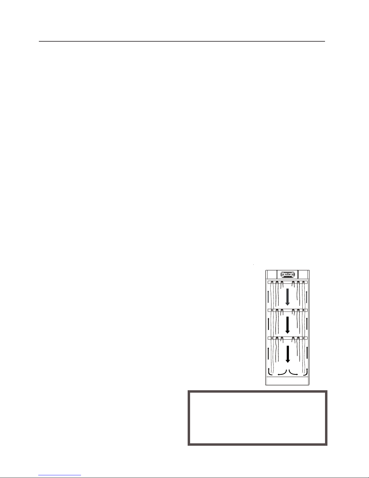
AIRFLOW
The gure shows the
airow in the drying
cabinet.
Keep the area
around the evacuation duct clear of
dust and dirt.
Make sure that the
air intake and exhaust air duct are
not blocked.
Remember not to hang knitted
articles. These can be needlessly
stretched when they are heavy with
water.
Page 18
MAN
60°
40°
-
+
MAN 40° 2:30
C
START
STOPP
ON
OFF
ECO DRYER
1 2
3
4
5
6 7 8 9
MAN 40° 2:30
C
START
STOPP
ECO DRYER
10 11
12
18
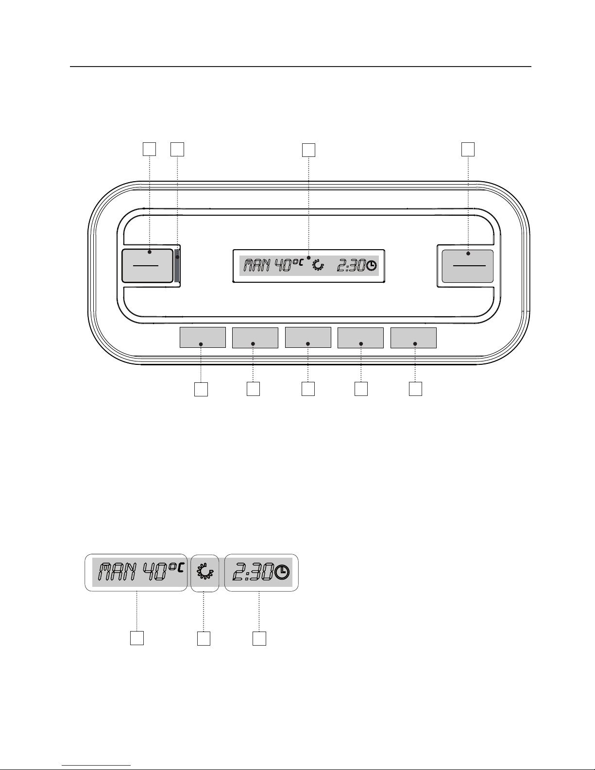
CONTROL PANEL
1. Main power switch
2. Main power on indicator - ON
3. Display
4. Programme Start/Stop
5. Automatic programme 40°
6. Automatic programme 60°
7. Manual time control - Step
function
8. Reduces standard time for time
control
9. Increases standard time for time
control
DISPLAY
10. Current programme selection
11. Revolving symbol - indicating that the
drying process is in progress
12. With manually programmes:
Programmed drying time
Time remaining - when the drying
programme has started
12. With automatic programme:
Time remaining - N.B.! Only during
the cooling down period
USING THE ETS 1700E / ETS 1900E DRYING CABINET
Page 19

19
DRYING PROGRAMME
The drying cabinet is equipped with two automatic programmes:
AUT 40°
AUT 60°
In addition, the drying cabinet has four time-controlled programmes:
MAN 30°
MAN 40°
MAN 60°
MAN --° Only the fan is used during the drying process – No heat
The automatic programmes shut o the drying process automatically when the
fabrics are dry.
The manually time-controlled programmes come to an end after the set time has
been counted down.
All the 30°, 40° and 60° programmes nish with a cooling down period of 10 minutes.
DRYING FUNCTION
Start the drying programme:
Last used drying programme.
Press the main power switch (1) to the ON position - Indicated by a green light (2)
The display shows the last run programme – If this is the one wanted, press the
START/STOP button (4)
Or select another drying programme described below.
Automatic programmes.
Automatic programme 40°- Press the ” 40°” button (5), then START/STOP (4).
Automatic programme 60°- Press the ” 60°” button (6), then START/STOP (4)
Manual time control.
Using the MAN button (7) to step through to the desired temperature, 30°, 40°, 60° or
only fan. The display shows the standard drying time for the respective programme.
The standard time can, if desired, be increased or reduced with the ”+” (8) or
”-” (9) buttons
After that, the drying programme is started with the START/STOP button (4).
USING THE ETS 1700E / ETS 1900E DRYING CABINET
Page 20
20
Door open
If the door is open when the drying programme is started and the START/STOP
button (4) is activated, the display shows ”CLOSE DOOR”. Close the door and
the selected drying programme will start.
During operation
The revolving symbol on the display indicates that the drying process is in progress.
Cooling down
During the cooling down period, the display shows the text ”COOL” in the pro-
gramme selection eld.
The time is counted down in the remaining time eld (10 minutes).
End of programme
When the cooling down period is complete, the drying process is nished. The
display shows the text ”END” (ashing).
When the START/STOP button (4) is pressed or the door is opened, the pro-
gramme currently running ends and the display shows the last programme used.
Stop
To interrupt the drying process in progress, press START/STOP (4).
The door opens
Should the door open while the drying process is in progress, the heat is shut
o (if the interrupted programme uses heat). The fan continues to work for a
further 5 minutes. The display shows ”CLOSE DOOR” and, at the same time, the
5 minute period count down.
If the door is shut within this 5 minute period, the drying process continues, as described below.
Automatic programme:
Starts again from the beginning = longer drying time.
Manual time control:
Goes back and starts from the interrupted count down sequence.
Should the door be left open, the drying process is interrupted after 5 minutes
and must be started again manually.
If you wish to interrupt the drying process directly, without the 5 minute period,
press START/STOP (4)
USING THE ETS 1700E / ETS 1900E DRYING CABINET
NOTE In waiting mode the display is turned off after 10 minutes and lights up when
any of the buttons on the control panel are activated or the door is opened.
Page 21

21
BREAKDOWNS
Protection against overheating
The drying cabinet is equipped with an overheating protection device which trips if
the temperature in the cabinet becomes too high. When the protection device trips,
the power supply to the drying cabinet main power switch (1) is interrupted and
the green indicator light (2) goes out. In this case the drying cabinet will not start.
When the temperature in the drying cabinet has sunk to an acceptable level, the
overheating protection device is reset automatically and the green indicator (2)
lights up (N.B.! If the main power switch (1) is on the ON position - pressed in).
It takes about 15-20 minutes for the temperature to sink to an acceptable level.
Therefore, if the drying cabinet has recently been used and if the green indicator
(2) will not light up with the main power switch (1), always wait a minimum of 20
minutes. Then make a new attempt to start it before reporting the fault.
If repeated breakdowns occur, contact your supplier.
The two automatic programmes of the drying cabinet can be optimised to match
the installation conditions.
To do this, use the control panel to adjust the parameter values for the relevant
automatic programme.
Only do this if you think that:
The washing is not being suciently dried
The washing is being over-dried – excessive drying time.
See the parameter adjustment instructions on page 26.
AUTOMATIC PROGRAMMES SETTING THE PARAMETERS
USING THE ETS 1700E / ETS 1900E DRYING CABINET
Page 22
22
USING THE ETS 1700 / 1900 DRYING CABINET
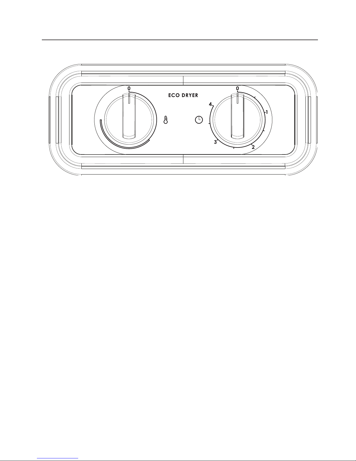
Temperature Drying time
SETTINGS
The cabinet is provided with two selector knobs for setting the positions for
dierent power modes.
The left selector knob regulates heat on
a continuous scale.
The right selector knob regulates drying
time on a continuous scale up to four
hours.
If a quick drying result is needed, turn the
temperature selector knob to its maximum and set the timer to two hours.
For a more normal drying time, the temperature selector knob is set to a point
immediately after the beginning of the
semi-circle and the timer between three
and four hours. This means considerably
lower energy consumption.
Page 23
ETS 1700E/1900E
TS 560-E
MAN
60°
40°
+
MAN 40° 2:30
C
START
STOPP
ON
OFF
ECO DRYER
23
CARE
The walls of the cabinet should be
cleaned with a mild soap solution
on a damp cloth.
Dust frequently gathers around the
air intake orice under the cabinet
and on the upper part of the cabinet.
This can disrupt operation of the
cabinet, leading to stoppages.
CLEANING
NOTE High-pressure cleaning should
not be used!
SERVICE
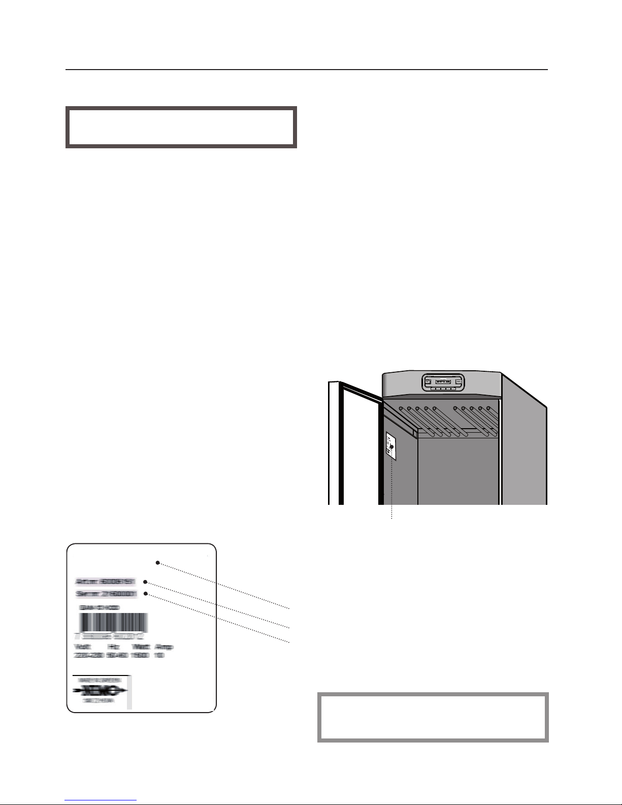
Before contacting Service, you should
find out the name, article and serial
number of the cabinet.
This information can be found on the
data plate located inside the cabinet.
Name of the drying cabinet
Article number
Serial number (12 digits)
Follow NIMO instructions when carrying out repairs or replacing parts.
To avoid this problem, the dust
should be removed by suction from
the air intake orice and the top of
the cabinet at least once a year or
more often depending on the environment the cabinet is located in.
Page 24

24
TECHNICAL DATA ETS 1700E / 1900E
Capacity: approx. 4,0 kg washing (cotton)
Dewatering capacity: 4/10/17 g/min.
Electrical connections: single-phase 230 V, 50-60 Hz
Motor: 35 W
Heating element: 750/1500 W
Overheating cut-out: Yes
Fan capacity: 180 m³/h
Hanging length: 16 metres
Dimensions: Height: ETS 1700E 1700 mm
ETS 1900E 1900 mm
Depth: 610 mm
Width: 595 mm
Weight: ~54/56 kg
Sound level: maximum 60 dB (A)
ENERGY CONSUMPTION AND DRYING TIME WHEN DRYING SPUN WASHING
Programme Energy consumption Drying time Temp. maximum
kWh/kg washing
AUT 40°C 0.4
approx. 2 h
approx. 45°C
AUT 60°C 0.6
approx. 2 h
approx. 65°C
MAN 30°C 0.3 (2 h 30 min)
manual setting 15 min - 6 h
approx. 35°C
MAN 40°C 0.4 (2 h 30 min)
manual setting 15 min - 4 h
approx. 45°C
MAN 60°C 0.6 (2 h 30 min)
manual setting 15 min - 4 h
approx. 65°C
MAN -- °C 0.08 (8 h)
manual setting 15 min - 12 h
only fan
*) Given values may vary depending on:
- spin speed
- temperature and air humidity in the room
- air circulation in the room (supply air, exhaust air)
*)
MANUFACTORING
STANDARD
See the identification plate
ELECTRICAL
DIAGRAM
The electrical circuit
diagram can be ordered from the manufacturer. Address
- see page 2.
Page 25
25
TECHNICAL DATA ETS 1700 / 1900
Capacity: approx. 4,0 kg washing (cotton)
Dewatering capacity: 17 g/min.
Electrical connections: single-phase 230 V, 50-60 Hz
Motor: 35 W
Heating element: 1500 W
Overheating cut-out: Yes
Timer: Can be set up to 4 hr
Fan capacity: 180 m³/h
Hanging length: 16 metres
Dimensions: Height: ETS 1700 1700 mm
ETS 1900 1900 mm
Depth: 610 mm
Width: 595 mm
Weight: ~54/56 kg
Sound level: maximum 60 dB (A)
ENERGY CONSUMPTION AND DRYING TIME WHEN DRYING SPUN WASHING *
Setting Energy consumption Drying time Heat
kWh/kg washing
Economy 0.5 approx. 3 h 45°C
Fast 0.7 approx. 2 h 60°C
*) Given values may vary depending on:
- spin speed
- temperature and air humidity in the room
- air circulation in the room (supply air, exhaust air)
MANUFACTORING
STANDARD
See the identification plate
ELECTRICAL
DIAGRAM
The electrical circuit
diagram can be ordered from the manufacturer. Address
- see page 2.
Page 26
MAN
60°
40°
-
+
MAN 40° 2:30
C
START
STOPP
ON
OFF
ECO DRYER
26
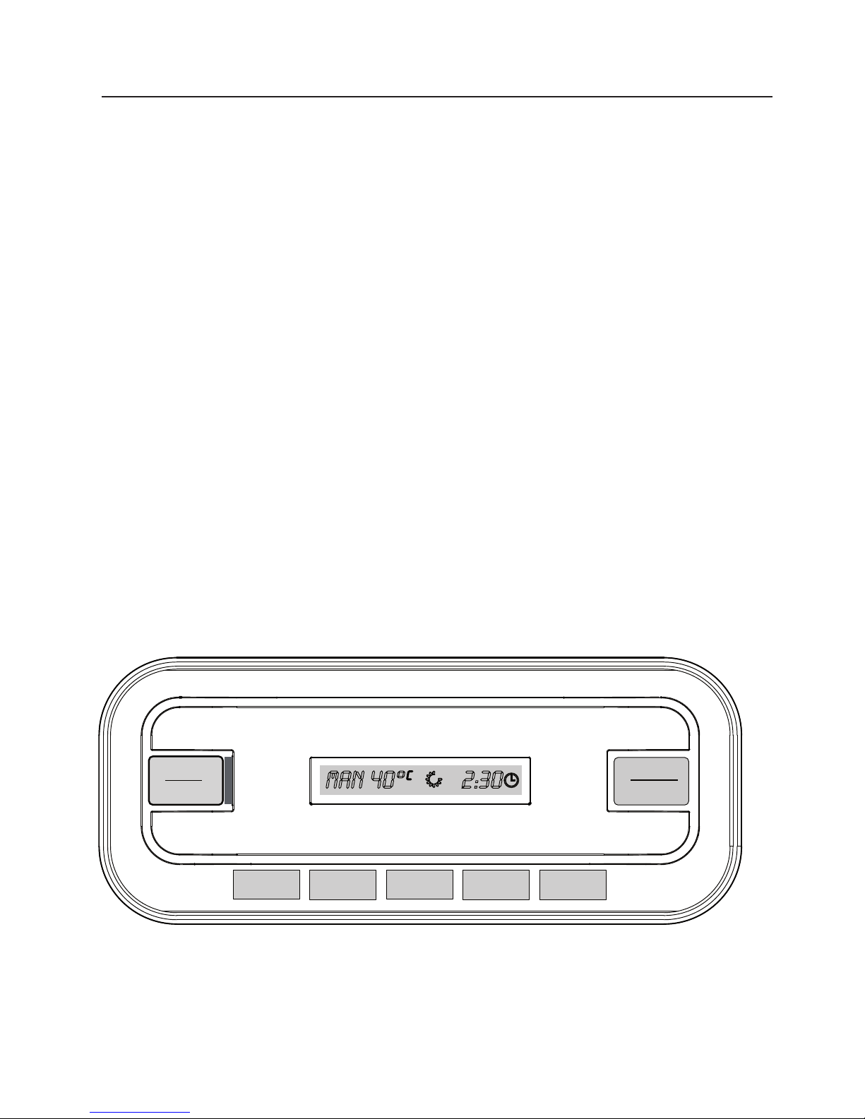
INTRODUCTION
The drying cabinet has two automatic
programmes, one for 40 °C and one
for 60 °C.
The automatic programmes end when
the washing is dry.
To determine when the washing is dry,
the programmes measure the temperature in the exhaust duct of the drying
cabinet and compare it with a parameter
set at the factory,
parameter P4 for the 40 °C
programme and
parameter P8 for the 60 °C
programme.
These are the two main parameters
to be adjusted to optimise the drying
process of the automatic programme.
If you think that the washing is not
being sufficiently dried, increase
the value of the parameter for the
relevant programme.
If you think that the washing is being
over-dried (long drying time), reduce
the value of the parameter for the
relevant programme.
Drying processes should always be optimised in small steps. Begin by adjusting
the relevant parameter up or down by 1
to 2 units. Then check the result after the
next drying process and adjust further if
necessary.
PARAMETER ADJUSTMENT ETS 1700E / 1900E
Page 27

27
PARAMETER ADJUSTMENT
Use the control panel to access the parameter list of the drying cabinet. The
parameter list appears one line at a time
on the control panel display.
Procedure:
1 Make sure that the main ON/OFF
switch of the drying cabinet is o and
that the indicator ( item 2) is also o.
2 Hold down the minus “-” and plus
“+” buttonsand set the main ON/
OFF switch to “ O N ”. This is indicated
by a green light . The display lights up
and shows “P1” (parameter 1) and
the factory setting for P1.
3 Press the “MAN” button several
times to step to the required parameter. If you overshoot, continue
pressing until the display shows the
correct parameter.
4
When the display shows the correct
parameter (P8, for example), use the
plus and minus buttons to increase or
reduce the setting.
5 To save the settings and return to
operating mode, press the START/
STOP button. The display now
shows the last programme used.
NOTE: How to restore the parameters
to the factory settings:
1 Go to parameter display mode as
explained at steps 1 and 2 above.
2 Hold down the “40°” button and
press the START/STOP button. The
parameter list re-appears and the
display shows Parameter 1 and the
factory setting for P1.
3 To save the factory settings and
return to operating mode, press the
START/STOP button. The display
now shows the last programme
PARAMETER ADJUSTMENT ETS 1700E / 1900E
Page 28

Gematech Innovation
 Loading...