

Page 1

Terra™ 4300B
INSTRUCTIONS FOR USE
Advance Model: 9084317010
ENGLISH
INSTRUCTIONS D’UTILISATION
Modèle Advance: 9084317010
FRANÇAIS
INSTRUCCIONES DE USO
Modelo Advance: 9084317010
ESP AÑOL
INSTRUÇÕES DE USO
Modelo Advance: 9084317010
PORTUGUÊS
1464035000(1)2009-06
https://harrissupplyind.com - To Order Parts Call 608-268-8080
Page 2

https://harrissupplyind.com - To Order Parts Call 608-268-8080
Page 3

INSTRUCTION FOR USE
ENGLISH
Terra™ 4300B 1464035000(1)2009-06
1
TABLE OF CONTENTS
INTRODUCTION ............................................................................................................................................................ 2
MANUAL PURPOSE AND CONTENTS .................................................................................................................... 2
TARGET .................................................................................................................................................................... 2
HOW TO STORE THIS MANUAL ............................................................................................................................. 2
IDENTIFICATION DATA ............................................................................................................................................ 2
OTHER REFERENCE MANUALS ............................................................................................................................ 2
SPARE PARTS AND MAINTENANCE ...................................................................................................................... 3
CHANGES AND IMPROVEMENTS .......................................................................................................................... 3
OPERATION CAPABILITIES ..................................................................................................................................... 3
CONVENTIONS ........................................................................................................................................................ 3
UNPACKING/DELIVERY ............................................................................................................................................... 3
SAFETY ......................................................................................................................................................................... 4
SYMBOLS ................................................................................................................................................................. 4
GENERAL INSTRUCTIONS ..................................................................................................................................... 4
KNOW YOUR MACHINE ............................................................................................................................................... 6
MACHINE NOMENCLATURE ................................................................................................................................... 6
CONTROL PANEL ..................................................................................................................................................... 8
ACCESSORIES/OPTIONS ....................................................................................................................................... 8
TECHNICAL DATA .................................................................................................................................................... 9
WIRING DIAGRAM ................................................................................................................................................. 10
USE .............................................................................................................................................................................. 12
BATTERY CHECK/SETTING ON A NEW MACHINE .............................................................................................. 12
WET OR GEL BATTERY SETTING ........................................................................................................................ 13
BEFORE MACHINE START-UP .............................................................................................................................. 13
STARTING AND STOPPING THE MACHINE ......................................................................................................... 14
PARKING BRAKE ................................................................................................................................................... 14
MACHINE OPERATION .......................................................................................................................................... 15
HOPPER DUMPING ............................................................................................................................................... 15
AFTER USING THE MACHINE ............................................................................................................................... 15
PUSHING/TOWING THE MACHINE ....................................................................................................................... 15
MACHINE STORAGE ............................................................................................................................................. 15
FIRST PERIOD OF USE ......................................................................................................................................... 15
MAINTENANCE ........................................................................................................................................................... 16
SCHEDULED MAINTENANCE TABLE ................................................................................................................... 16
MAIN BROOM HEIGHT CHECK AND ADJUSTMENT ........................................................................................... 17
MAIN BROOM REPLACEMENT ............................................................................................................................. 18
SIDE BROOM HEIGHT CHECK AND ADJUSTMENT ............................................................................................ 19
SIDE BROOM REPLACEMENT .............................................................................................................................. 19
DUST FILTER CLEANING AND INTEGRITY CHECK ............................................................................................ 20
SKIRT HEIGHT AND OPERATION CHECK ............................................................................................................ 21
BATTERY CHARGING ............................................................................................................................................ 22
FUSE CHECK/REPLACEMENT/RESET ................................................................................................................ 23
SAFETY FUNCTIONS ................................................................................................................................................. 23
EMERGENCY PUSH-BUTTON .............................................................................................................................. 23
DRIVER’S SEAT MICROSWITCH .......................................................................................................................... 23
TROUBLESHOOTING ................................................................................................................................................. 24
SCRAPPING ................................................................................................................................................................ 24
https://harrissupplyind.com - To Order Parts Call 608-268-8080
Page 4

ENGLISH
INSTRUCTION FOR USE
2
1464035000(1)2009-06 Terra™ 4300B
INTRODUCTION
NOTE
The numbers in brackets refer to the components shown in KNOW YOUR MACHINE chapter.
MANUAL PURPOSE AND CONTENTS
The purpose of this Manual is to provide the operator with all necessary information to use the machine properly, in a safe and
autonomous way. It contains information about technical data, safety, operation, storage, maintenance, spare parts and disposal.
Before performing any procedure on the machine, the operators and qualifi ed technicians must read this Manual carefully. Contact
Advance in case of doubts concerning the interpretation of the instructions and for any further information.
TARGET
This Manual is intended for operators and technicians qualifi ed to perform the machine maintenance.
The operators must not carry out operations reserved for qualifi ed technicians. Advance will not be responsible for damages coming
from failure to follow these instructions.
HOW TO STORE THIS MANUAL
The User Manual must be kept near the machine, inside an adequate case, away from liquids and other substances that can cause
damage to it.
IDENTIFICATION DATA
The machine model and serial number are marked on the plate (37).
The machine model year is indicated by the fi rst two fi gures of the machine serial number.
This information is useful when requiring machine spare parts. Use the following table to write down the machine identifi cation data.
MACHINE model ...............................................................................
MACHINE serial number ...................................................................
OTHER REFERENCE MANUALS
Other manuals supplied with the machine:
Electronic Battery Charger Manual, to be considered an integral part of this Manual –
Sweeper Spare Parts List –
Other available manuals:
Service Manual (that can be consulted at any Advance Dealer) –
https://harrissupplyind.com - To Order Parts Call 608-268-8080
Page 5

INSTRUCTION FOR USE
ENGLISH
Terra™ 4300B 1464035000(1)2009-06
3
SPARE PARTS AND MAINTENANCE
All necessary operating, maintenance and repair procedures must be performed by qualifi ed personnel or by Advance Dealers.
Only original spare parts and accessories must be used.
Call Advance for service or to order spare parts and accessories, specifying the machine model and serial number.
CHANGES AND IMPROVEMENTS
Advance constantly improves its products and reserves the right to make changes and improvements at its discretion without being
obliged to apply such benefi ts to the machines that were previously sold.
Any change and/or addition of accessory must be approved and performed by Advance.
OPERATION CAPABILITIES
This sweeper has been designed and built to be used by a qualifi ed operator to sweep/clean smooth and solid fl oors, in civil and
industrial environments, and to collect dust and light debris under safe operation conditions.
CONVENTIONS
Forward, backward, front, rear, left or right are intended with reference to the operator’s position, while on the driver’s seat (25).
UNPACKING/DELIVERY
To unpack the machine carefully follow the instructions on the packing.
Upon delivery check that the packing and the machine were not damaged during transportation. In case of visible damages, keep
the packing and have it checked by the carrier that delivered it. Call the carrier immediately to fi ll in a damage claim.
Check that the machine is equipped as follows:
Technical documents: –
Sweeper User Manual•
Electronic Battery Charger Manual•
Sweeper Spare Parts List•
No. 1 70 A fuse –
https://harrissupplyind.com - To Order Parts Call 608-268-8080
Page 6

ENGLISH
INSTRUCTION FOR USE
4
1464035000(1)2009-06 Terra™ 4300B
SAFETY
The following symbols indicate potentially dangerous situations. Always read this information carefully and take all necessary
precautions to safeguard people and property.
The operator’s cooperation is essential in order to prevent injury. No accident prevention program is effective without the total
cooperation of the person responsible for the machine operation. Most of the accidents that may occur while working or moving
around are caused by failure to comply with the simplest rules for exercising prudence. A careful and prudent operator is the best
guarantee against accidents and is essential for successful completion of any prevention program.
SYMBOLS
DANGER!
It indicates a dangerous situation with risk of death for the operator.
WARNING!
It indicates a potential risk of injury for people or damage to objects.
CAUTION!
It indicates a caution or a remark related to important or useful functions. Pay careful attention to the
paragraphs marked by this symbol.
NOTE
It indicates a remark related to important or useful functions.
CONSULTATION
It indicates that it is necessary to consult the User Manual before performing any procedure.
GENERAL INSTRUCTIONS
Specifi c warnings and cautions to inform about potential damages to people and machine are shown below.
DANGER!
Before performing any maintenance, repair, cleaning or replacement procedure disconnect the battery –
connector, remove the ignition key and engage the parking brake.
This machine must be used by properly trained operators only. Children or disabled people cannot use this –
machine.
Sharp turns must be made at slowest possible speed. Avoid abrupt turns on incline. –
Do not wear jewels when working near electrical components. –
Keep the battery away from sparks, fl ames and incandescent material. During the normal operation –
explosive gases are released.
Do not work under the lifted machine without supporting it with safety stands. –
When working under the open hood, ensure that it cannot be closed by accident. –
Do not operate the machine near toxic, dangerous, fl ammable and/or explosive powders, liquids or –
vapours: This machine is not suitable for collecting dangerous powders.
If the machine is equipped with lead (WET) batteries, battery charging produces highly explosive hydrogen –
gas. Keep the hood open when charging the batteries and perform this procedure in well-ventilated areas
and away from naked fl ames.
When lead batteries (WET) are installed on this machine, do not tilt the machine more than 30° from its –
horizontal position to prevent the highly corrosive acid to leak out of the batteries. When the machine is to
be tilted to perform maintenance procedures, remove the batteries.
https://harrissupplyind.com - To Order Parts Call 608-268-8080
Page 7
INSTRUCTION FOR USE
ENGLISH
Terra™ 4300B 1464035000(1)2009-06
5
WARNING!
Carefully read all the instructions before performing any maintenance/repair procedure. –
Take all necessary precautions to prevent hair, jewels and loose clothes from being caught by the machine –
moving parts.
Before using the battery charger, ensure that frequency and voltage values, shown on the machine serial –
number plate, match the electrical mains voltage.
Do not pull or carry the machine by the battery charger cable and never use the battery charger cable as –
a handle. Do not close a door on the battery charger cable, or pull the battery charger cable around sharp
edges or corners. Do not run the machine on the battery charger cable.
Keep the battery charger cable away from heated surfaces. –
Do not charge the batteries if the battery charger cable or the plug are damaged. If the battery charger cable –
is damaged, contact Advance Dealer.
To reduce the risk of fi re, electric shock, or injury, do not leave the machine unattended when it is plugged –
in. Before performing any maintenance procedure, disconnect the battery charger cable from the electrical
mains.
To avoid any unauthorised use of the machine, remove the ignition key. –
Do not leave the machine unattended without being sure that it cannot move independently. –
Do not use the machine on slopes with a gradient exceeding the specifi cations. –
Use only brooms supplied with the machine and those specifi ed in the User Manual. Using other brooms –
could reduce safety.
Before using the machine, close all doors and/or covers. –
Do not use the machine in particularly dusty areas. –
Use the machine only where a proper lighting is provided. –
If the machine is to be used where there are other people besides the operator, it is necessary to install the –
pivoting light (optional).
Do not wash the machine with direct or pressurised water jets, or with corrosive substances. Do not use –
compressed air to clean this type of machine, except for the fi lters (see the relevant paragraph).
While using this machine, take care not to cause damage to people and children especially. –
Do not put any can containing fl uids on the machine. –
The machine storage temperature must be 32°F to 104°F (0°C to +40°C).. –
The machine working temperature must be 32°F to 104°F (0°C to +40°C).. –
The humidity must be between 30% and 95%. –
Always protect the machine against the sun, rain and bad weather, both under operation and inactivity –
condition. Store the machine indoors, in a dry place. This machine must be used in dry conditions, it must
not be used or kept outdoors in wet conditions.
Do not use the machine as a means of transport, or for pushing/towing. –
Do not allow the brooms to operate while the machine is stationary to avoid damaging the fl oor. –
In case of fi re, use a powder fi re extinguisher, not a water one. –
Do not bump into shelves or scaffoldings, particularly where there is a risk of falling objects. –
Adjust the operation speed to suit the fl oor conditions. –
Avoid sudden stops when the machine is going downhill. Avoid sharp turns. Drive at slow speed when –
going downhill.
This machine cannot be used on roads or public streets. –
Do not tamper with the machine safety guards. –
Follow the routine maintenance procedures scrupulously. –
Do not remove or modify the plates affi xed to the machine. –
In case of machine malfunctions, ensure that these are not due to lack of maintenance. Otherwise, request –
assistance from the authorised personnel or from an authorised Service Center.
In case of part replacement, order ORIGINAL spare parts from an authorised Dealer or Retailer. –
To ensure the proper and safe operation of the machine, have the scheduled maintenance, detailed in the –
relevant chapter of this Manual, performed by the authorised personnel or an authorised Service Center.
The machine must be disposed of properly, because of the presence of toxic-harmful materials (batteries, –
oil, plastics, etc.), which are subject to standards that require disposal in special centres (see Scrapping
chapter).
https://harrissupplyind.com - To Order Parts Call 608-268-8080
Page 8

ENGLISH
INSTRUCTION FOR USE
6
1464035000(1)2009-06 Terra™ 4300B
KNOW YOUR MACHINE
MACHINE NOMENCLATURE
Steering wheel1.
Forward/reverse gear pedal2.
Service brake pedal3.
Parking brake lever4.
Press the brake pedal (3), then use the lever (4) to switch
from the service brake to the parking brake.
Front skirt lifting pedal5.
Can holder6.
Hood7.
Rear driving wheels on fi xed axle8.
Front steering wheel9.
Right side broom10.
Left side broom11.
Main broom12.
Left side skirt13.
Right side skirt14.
Front skirt15.
Rear skirt16.
Hopper (empty it when it is full)17.
Hopper fastening hook18.
Hopper handle19.
Left door (to be opened for performing maintenance 20.
procedures only)
Door knobs21.
Left door (for main broom removal)22.
Door knobs23.
Flashing light (always on when the ignition key is turned to 24.
“I”) (optional)
Driver’s seat with safety microswitch25.
Additional hole for manual vacuum system kit (optional)26.
Adjustable steering column27.
Working light (optional)28.
Right side broom height adjusting knob29.
Left side broom height adjusting knob30.
Seat longitudinal position adjusting lever31.
Vacuum fi lter compartment cover32.
Cover knobs33.
Manual vacuum system (optional)34.
Manual vacuum system fasteners35.
Internal containers with handle for dumping (optional)36.
Serial number plate/technical data/conformity certifi cation37.
Hood opening handles38.
Machine lifting anchors39.
36
36
17
17
18
16
12
19
33
32
33
22
23
14
35
34
37
26
35
34
6
7
24
25
1
31
27
2
3
4
5
8
21
20
13
15
11
30
9
28
10
29
38
38
39
39
39
39
8
P100344
https://harrissupplyind.com - To Order Parts Call 608-268-8080
Page 9
INSTRUCTION FOR USE
ENGLISH
Terra™ 4300B 1464035000(1)2009-06
7
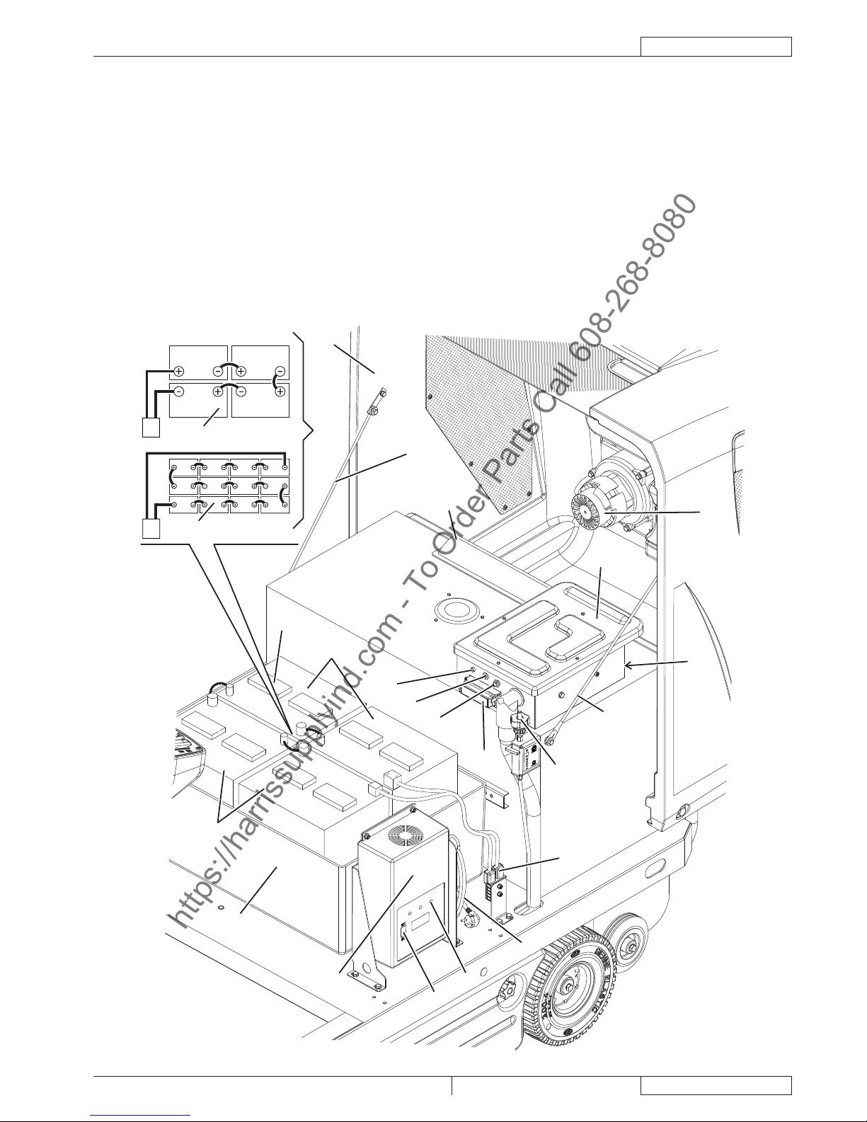
MACHINE NOMENCLATURE (Continues)
Hood (open)41.
Hood support tie rods42.
Lead batteries (WET) or optional gel batteries (GEL)43.
Battery connection diagram44.
Battery caps (for WET batteries only)45.
Battery connector46.
Electronic battery charger47.
Battery charger cable48.
Lead (WET) or gel (GEL) battery selector on the optional 49.
electronic battery charger
Charged battery warning light50.
Lamellar fuse box51.
Main broom motor fuse52.
Side broom motor fuse53.
Drive system malfunction led.54.
If the led is on, the drive system is operating, if the led
fl ashes, the drive system is malfunctioning.
Electrical component box55.
Drive system electronic board56.
Battery case57.
Manual vacuum system (optional)58.
Main broom height adjusting knob59.
Air baffl e plate60.
6V
24V
6V
6V 6V
44
41
42
58
55
59
54
53
52
51
46
48
50
49
57
47
43
43
43
42
56
60
43
45
P100345
https://harrissupplyind.com - To Order Parts Call 608-268-8080
Page 10

ENGLISH
INSTRUCTION FOR USE
8
1464035000(1)2009-06 Terra™ 4300B
CONTROL PANEL
Left control panel71.
Ignition key (when turned to “0” it turns the machine off 72.
and disables all functions; when turned to “I” it enables all
machine functions; it also turns on the fl ashing light)
Discharged battery warning light (red). When it is on, 73.
the batteries are discharged. The autonomy is over, the
batteries must be recharged (see the procedure in the
relevant paragraph).
Semi-discharged battery warning light (yellow). When it is 74.
on, the batteries are semi-discharged. Residual autonomy
is few minutes.
Charged battery warning light (green). When it is on, the 75.
batteries are charged. Residual autonomy depends on
battery capacity and working conditions.
Display. When pressed, it shows in sequence:76.
Working hours•
Last digit of the hours - (dot) - minutes•
Battery voltage (V)•
Display selection push-button: hour counter/hour and 77.
minute counter/battery voltage (V)
Horn switch78.
Vacuum fan/fi lter shaker switch79.
Manual vacuum system additional hole switch (optional)80.
Working light switch (optional)81.
Emergency push-button82.
Press it in case of emergency to stop all the machine
functions. To deactivate the emergency push-button, turn it
in the direction shown by the arrow.
Panel fastening screws83.
Right control panel84.
Left and right side broom lifting/lowering lever85.
Main broom lifting/lowering lever86.
Steering wheel adjusting lever87.
O
F
F
O
N
86
77
73
74
75
76
84
78
85
82
71
79
81
80
83
87
83
72
P100346
ACCESSORIES/OPTIONS
In addition to the standard components, the machine can be equipped with the following accessories/options, according to the
machine specifi c use:
GEL batteries –
Main and side brooms with harder or softer bristles –
Antistatic polyester or polyester BIA C dust fi lter –
Manual vacuum system –
Working light –
Flashing light –
Skirts of various materials –
Overhead guard –
For further information about the above-mentioned accessories, contact an authorised Retailer.
https://harrissupplyind.com - To Order Parts Call 608-268-8080
Page 11

INSTRUCTION FOR USE
ENGLISH
Terra™ 4300B 1464035000(1)2009-06
9
TECHNICAL DATA
General
Values
Machine length
58.3 in (1.480 mm)
Machine width (without side brooms)
36.6 in (930 mm)
Machine maximum height (at the steering wheel)
48.0 in (1.220 mm)
Cleaning width (without side brooms)
27.6 in (700 mm)
Working width (with two side brooms)
49.6 in (1.260 mm)
Minimum distance from the fl oor (skirts not included)
2.2 in (55 mm)
Main broom size (diameter x length)
11.8 x 27.6 in (300 mm x 700 mm)
Side broom diameter
16.5 in (420 mm)
Main broom speed
550 rpm
Side broom speed
80 rpm
Front steering wheel diameter
9.8 in (250 mm)
Rear driving wheel diameter
9.8 in (250 mm)
Front wheel specifi c pressure on the fl oor
159.5 psi (1.1 N/mm
2
)
Rear wheel specifi c pressure on the fl oor
101.5 psi (0.7 N/mm
2
)
Total machine weight (without batteries)
573.2 in (260 kg)
Hopper capacity
18.5 gal (70 litres)
Main broom motor
0.67 hp (500 W)
Side broom motors
0.08 hp (60 W)
Drive system motor
0.8 hp (600 W), 110 rpm
Vacuum system motor
0.41 hp (310 W)
Filter shaker motor
0.12 hp (90 W), 6.000 rpm
Sound pressure level at workstation (ISO 11201, ISO 4871) (LpA)
63,8 ±3 dB(A)
Machine output acoustic power (ISO 3744, ISO 4871) (LwA)
84 dB(A)
Vibration level at the operator’s arms (ISO 5349-1) (*)
< 8.2 ft/s
2
(< 2,5 m/s2)
Vibration level at the operator’s body (ISO 2631-1) (*)
1.9 ft/s
2
(0,6 m/s2)
Under normal working conditions, on a level asphalt surface.(*)
Performance
Values
Maximum forward/reverse speed
3.7 mph (6 km/h)
Maximum reverse speed
1.8 mph (3 km/h)
Gradeability
11.3° (20 %)
Minimum turning radius
51.6 in (1.310 mm)
Batteries
Values
Battery voltage
24 V
Standard battery Lead with acid electrolyte (WET)
Optional battery Gel, hermetic (GEL)
Battery minimum capacity (with battery charger)
185 Ah C5
Battery maximum capacity
256 Ah C5
Battery case inner size (length x width x height)
24.8 x 16.5 x 14.5 in (630 x 420 x 370 mm)
Battery compartment maximum size (width x length x height)
26.0 x 17.3 x 16.6 in (660 x 440 x 370 mm)
Dust vacuuming and fi ltering
Values
Paper dust fi lter 5-10 m
14.1 ft
2
(4,3 m2)
Main broom compartment vacuum
0.43 in H
2
O (11 mm H2O)
Filter shaker activation
Electric
https://harrissupplyind.com - To Order Parts Call 608-268-8080
Page 12

ENGLISH
INSTRUCTION FOR USE
10
1464035000(1)2009-06 Terra™ 4300B
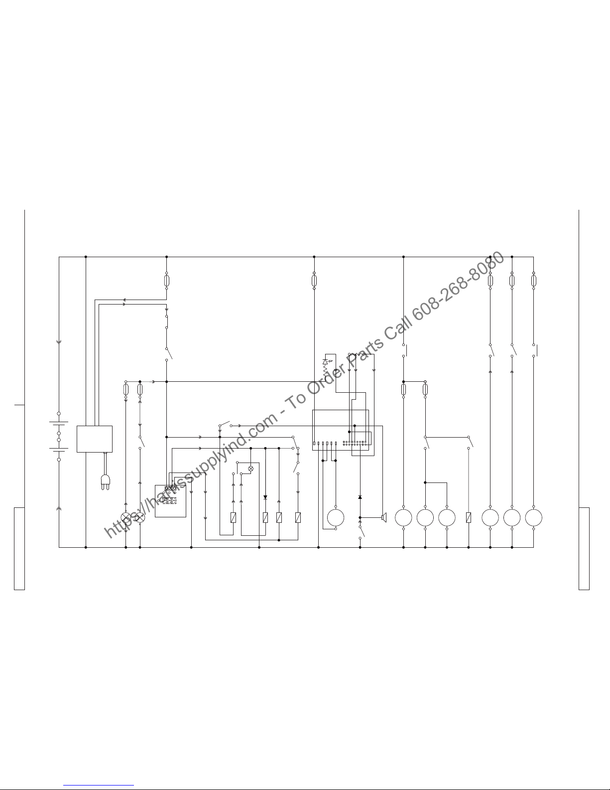
WIRING DIAGRAM
Key
BAT Batteries
BE1 Flashing light (optional)
BZ1 Reverse gear buzzer/horn
C1 Battery connector
C2 Battery charger sub-connector
CH1 Battery charger
EB1 Hour counter and battery voltage display
EB2 Drive system electronic board
ES1 Main broom relay
ES2 Filter shaker relay
ES3 Vacuum system relay
ES4 Manual vacuum system relay (optional)
ES5 Side broom relay
FA Main broom fuse
FB Side broom fuse
FT Drive system fuse (70 A)
F1 Main fuse (key circuit) (15 A)
F2 Filter shaker motor fuse (25 A)
F3 Manual vacuum system fuse (40 A) (optional)
F4 Vacuum system motor fuse (30 A)
F5 Horn and pivoting light fuse (10 A)
F6 Working light fuse (10 A) (optional)
K1 Ignition key
LD1 Drive system electronic board diagnostic led
L1 Working light (optional)
M1 Main broom motor
M2 Drive system motor
M3 Filter shaker motor
M4 Right side broom motor
M5 Left side broom motor
M6 Vacuum system motor
M7 Manual vacuum system motor (optional)
P1 Horn switch
R1 Drive speed potentiometer (pedal)
R2 Led resistance
SWS Emergency push-button
SW1 Main broom microswitch
SW2 Vacuum system/fi lter shaker switch
SW3 Manual vacuum system switch (optional)
SW4 Driver’s seat safety microswitch
SW5 Side broom microswitch
SW6 Working light switch (optional)
Colour code
BK Black
BU Light blue
BN Brown
GN Green
GY Grey
OG Orange
PK Pink
RD Red
VT Violet
WH White
YE Yellow
https://harrissupplyind.com - To Order Parts Call 608-268-8080
Page 13
INSTRUCTION FOR USE
ENGLISH
Terra™ 4300B 1464035000(1)2009-06
11
WIRING DIAGRAM (Continues)
BAT
CH
C1
C1
RDBK
BK
M1
BZ1
ES1
RD
FA
FR
K1
BU
SWS
BU
PK
BK
BE1
SW6
GY
ES1
EB1
BK
L1
GY
F6
BKM4BK
M5
FT
BK
M2
BK
M3
ES2
VT
F2
SW4
BK
M7
ES4
BN
F3
BU
C2
RD
RD
OG
GNBK
GNBK
RD
BU
WH
VT BN
RD
RD
RD
BK
BK
YE
WH
RD
BU
30
87
SW5
BUBK
ES4
BN
SW3
OG
FB
BK
M6
BU
F4
BU
ES3
30
87
OG
SW1
B+
B-
10
1
18
9
M2
M1
EB2
R1
RD
BU
YE
F5
P1
WH
BK
RD
BK
nanc
c
BN
nc
c
RD
ES3
WH
SW2
VT
mom.
ES2
RDBK
GNBK
BK
OG
BN
BU
YEGN
R2
LD1
OG
YEBK
1
2
3
8
7
ES5
30
87
ES5
BK
BUBK
YE
86
85
85
86
85
86
-
+
-
+
R R
S311411
https://harrissupplyind.com - To Order Parts Call 608-268-8080
Page 14

ENGLISH
INSTRUCTION FOR USE
12
1464035000(1)2009-06 Terra™ 4300B
USE
WARNING!
On some points of the machine there are some adhesive plates indicating:
DANGER –
WARNING –
CAUTION –
CONSULTATION –
While reading this Manual, the operator must pay particular attention to the symbols shown on the plates.
Do not cover these plates for any reason and immediately replace them if they are damaged.
BATTERY CHECK/SETTING ON A NEW MACHINE
WARNING!
If the machine must be pushed for service reasons (missing batteries, discharged batteries, etc.) do not exceed
2.5 mph (4 km/h).
NOTE
With electronic battery charger, this must be connected to the batteries to allow the machine to operate.
The machine requires four 6 V batteries, connected according to the diagram (44), or one 24 V battery box.
The machine can be supplied in one of the following confi gurations:
WET or GEL batteries already installed on the machinecj)
WET batteries installed on the machine but without electrolyteck)
Without batteriescl)
According to machine confi guration, proceed as follows.
WET or GEL batteries already installed on the machinea)
Open the machine hood (7) and check that the batteries are connected to the machine with the connector (46).1.
Close the hood (7).2.
Insert the ignition key (72) and turn it to “I” [without pressing the pedal (2)].3.
If the green warning light (75) turns on, the batteries are charged.
If the yellow (74) or red (73) warning light turns on, the batteries must be charged (see the procedure in Maintenance
chapter).
WET batteries installed on the machine but without electrolyteb)
Open the machine hood (7).1.
Remove all battery caps (45).2.
WARNING!
Pay attention when using sulphuric acid, as it is corrosive. If it comes in contact with skin or eyes, rinse
thoroughly with water and consult a physician.
Batteries have to be fi lled in a well-ventilated area.
Wear protective gloves.
Fill the battery cells with sulphuric acid for batteries [density 2.79 to 2.84 lb at 77°F (1.27 to 1.29 kg at 25°C)] according to 3.
the instructions shown in the Battery Manual.
The correct quantity of sulphuric acid is shown in the Battery Manual.
Let the batteries rest and fi ll in with sulphuric acid according to the instructions shown in the Battery Manual.4.
Charge the batteries (see the procedure in Maintenance chapter).5.
Without batteriesc)
Buy appropriate batteries (see the Technical Data paragraph and the diagram (44)).1.
For the battery choice and installation, apply to qualifi ed battery Retailers.
Install the batteries.2.
Set the machine and the battery charger according to the type of batteries installed, as shown in the next paragraph.3.
https://harrissupplyind.com - To Order Parts Call 608-268-8080
Page 15

INSTRUCTION FOR USE
ENGLISH
Terra™ 4300B 1464035000(1)2009-06
13
WET OR GEL BATTERY SETTING
NOTE
With electronic battery charger, this must be connected to the batteries to allow the machine to operate.
According to the type of batteries (WET or GEL), set the electronic board of the machine and the battery charger, according to the
following procedure:
Turn the ignition key (72) to “0”.1.
Open the hood (7).2.
Machine setting
The machine factory setting is for lead (WET) batteries. If this setting corresponds to the type of batteries installed on the 1.
machine, go to the next paragraph, otherwise perform the following procedures:
Disconnect the battery connector (46).•
Remove the screws (83) and carefully remove the right control panel (84).•
Install a jumper wire (A, Fig. 1) on “GEL” connectors (B) for gel batteries.•
Carefully install the control panel (84) and the relevant screws.•
Connect the battery connector (46).•
C
B
A
S311412
Figura 1
Battery charger setting
Turn the battery selector (49) to WET for lead batteries or to GEL for gel batteries.1.
Charge the batteries (see the procedure in Maintenance chapter).2.
BEFORE MACHINE START-UP
CAUTION!
Make sure that there are no open doors/hoods and that the machine is in normal operating conditions.
Make sure that the hopper (17) is properly closed.
If the machine has not been used after being transported, check that all the blocks used for the transportation
have been removed.
https://harrissupplyind.com - To Order Parts Call 608-268-8080
Page 16

ENGLISH
INSTRUCTION FOR USE
14
1464035000(1)2009-06 Terra™ 4300B
STARTING AND STOPPING THE MACHINE
Starting the machine
Sit on the driver’s seat (25).1.
If necessary, adjust the seat to a comfortable position by using the lever (31).2.
If necessary, use the lever (87) to tilt the steering column (1) forward or backward in order to reach a comfortable position.
Turn the ignition key (72) to “I” and do not press the pedal (2). Check that the green warning light (75) (charged battery) turns 3.
on.
If the yellow (74) or red warning light (73) turns on, turn the ignition key to “0” and charge the batteries (see the procedure in
Maintenance chapter).
Disengage the parking brake.4.
Drive the machine to the working area, by keeping the hands on the steering wheel and pressing the pedal (2) on the front side 5.
to move forward and on the rear side to move backward.
The drive speed can be adjusted from zero to maximum speed by increasing the pressure on the pedal (2).
NOTE
The seat (25) is equipped with a safety sensor, which allows the machine to be driven by pressing the pedal (2) only
when the operator is on the driver’s seat.
Lower the main broom with the lever (86); it will start turning.6.
Turn on the vacuum system by pushing the switch (79) backward.7.
NOTE
The vacuum system turns on only when the main broom is lowered.
Lower the side brooms (10 and 11) with the lever (85).8.
NOTE
The side brooms (10 and 11) can be lowered and lifted even when the machine is moving.
The side brooms do not turn when they are lifted or when the main broom is lifted.
Start sweeping by turning the steering wheel (1) and moving the machine forward by pressing the pedal (2).9.
Stopping the machine
To stop the machine release the pedal (2).1.
To stop the machine quickly, also press the service brake pedal (3).
In case of emergency, press the emergency push-button (82) to immediately stop the machine. To deactivate the emergency
push-button (82), turn it in the direction shown by the arrow.
Lift the side brooms (10 and 11) with the lever (85).2.
Turn off the vacuum system by bringing back the switch (79) to the centre.3.
Lift the main broom (12) with the lever (86).4.
To stop the machine, turn the ignition key (72) to “0”.5.
Engage the parking brake.6.
PARKING BRAKE
Engage the parking brake by pressing the pedal (3) and engaging the lever (4).1.
Disengage the parking brake by pressing and releasing the pedal (3).2.
WARNING!
Before performing any maintenance, repair, cleaning or replacement procedure engage the parking brake.
Engage the parking brake when parking the machine on a slope or incline.
https://harrissupplyind.com - To Order Parts Call 608-268-8080
Page 17
INSTRUCTION FOR USE
ENGLISH
Terra™ 4300B 1464035000(1)2009-06
15
MACHINE OPERATION
WARNING!
Pay careful attention when operating the machine at high speed: sudden steering could cause this three-wheel
machine to become unstable due to weight distribution.
Always reduce the speed before steering.
Avoid stopping for a long time with the machine in the same position and the brooms rotating: this could create unwanted 1.
marks on the fl oor.
To collect light and bulky waste materials, lift the front skirt by pressing the pedal (5); take into consideration that the machine 2.
vacuum capability is reduced when the front skirt is lifted.
CAUTION!
When operating on wet fl oors, it is essential to turn off the vacuum system by pressing the switch (79) to
prevent the dust fi lter from being damaged.
For machine proper operation, the dust fi lter must be as clean as possible. To clean it while sweeping, turn on the fi lter shaker 3.
by pressing the switch (79) forward for a few seconds.
During this operation the vacuum fan is automatically shut off.
After cleaning the fi lter, press the switch (79) backward to restart the vacuum system; then start sweeping again.
While working, repeat the procedure every 10 minutes on average (depending on the dustiness of the area to be cleaned).
NOTE
When the dust fi lter is clogged and/or the hopper is full, the machine cannot collect dust and debris anymore.
The hopper (17) should be emptied after each working cycle and whenever it is full (see the procedure in the following 4.
paragraph).
HOPPER DUMPING
Stop the machine by releasing the drive pedal.1.
Turn the ignition key (72) to “0”.2.
Engage the parking brake.3.
Disengage the hook (18) by pulling its lower end.4.
Remove the hopper (17) by using the handle (19) and by disengaging it from the inner guides.5.
Discharge all the debris into special containers. To make discharging procedure easier, inside the hopper there are two
different containers (optional) with handle (36).
Install the containers with handle (36), if equipped.6.
Install the hopper (17) and engage it to the inner guides, then fasten it with the hook (18).7.
The machine is ready to start sweeping again.8.
AFTER USING THE MACHINE
After working, before leaving the machine, perform the following procedures.
Lift the side brooms with the lever (85).1.
Lift the main broom with the lever (86).2.
Turn on the fi lter shaker with the switch (79).3.
Empty the hopper (17) (see the procedure in the previous paragraph).4.
Remove the ignition key (72).5.
Engage the parking brake.6.
PUSHING/TOWING THE MACHINE
To push/tow the machine when it is turned off, no special prearrangement is necessary.
MACHINE STORAGE
If the machine is not going to be used for more than 30 days, proceed as follows:
Check that the machine storage area is dry and clean.1.
Disconnect the battery connector (46).2.
FIRST PERIOD OF USE
After the fi rst period of use (fi rst 8 hours) it is necessary to perform the following procedures:
Check the fastening and connecting elements for proper tightening. –
Check the visible parts for integrity and leakages. –
https://harrissupplyind.com - To Order Parts Call 608-268-8080
Page 18

ENGLISH
INSTRUCTION FOR USE
16
1464035000(1)2009-06 Terra™ 4300B
MAINTENANCE
The lifespan of the machine and its maximum operating safety are ensured by correct and regular maintenance.
The following table provides the scheduled maintenance. The intervals shown may vary according to particular working conditions,
which are to be defi ned by the person in charge of the maintenance.
All scheduled or extraordinary maintenance procedures must be performed by qualifi ed personnel, or by an authorised Service
Center.
This Manual describes only the easiest and most common maintenance procedures.
For other maintenance procedures contained in the Scheduled Maintenance Table or for extraordinary maintenance procedures see
the Service Manual that can be consulted at any Service Center.
WARNING!
To perform maintenance procedures, the machine must be off, the ignition key removed, and, if necessary, the
batteries must be disconnected.
Read carefully the instructions in Safety chapter before performing any maintenance procedure.
SCHEDULED MAINTENANCE TABLE
Procedure Upon delivery
Every 10
hours
Every 50
hours
Every
100
hours
Every
200
hours
Every
400
hours
WET battery fl uid level check
Side and main broom height check and adjustment
Dust fi lter cleaning and integrity check
Skirt height and operation check
Filter shaker operation check (*)
Main broom driving belt visual inspection (*)
Nut and screw tightening check (*)(1)
Service and parking brake check and adjustment (*)
Steering chain check and cleaning (*)
Main broom driving belt replacement (*)
Main motor and drive system motor carbon brush check or replacement
(*)
For the relevant procedure, see the Service Manual.(*)
And after the fi rst 8 running-in hours.(1)
https://harrissupplyind.com - To Order Parts Call 608-268-8080
Page 19

INSTRUCTION FOR USE
ENGLISH
Terra™ 4300B 1464035000(1)2009-06
17
MAIN BROOM HEIGHT CHECK AND
ADJUSTMENT
NOTE
Brooms of various hardness are available. This
procedure is applicable to all types of brooms.
Check the main broom distance from the fl oor as shown 1.
below:
Drive the machine on a level fl oor.•
Keep the machine stationary, lower the main broom •
and turn it on for a few seconds.
Stop and lift the main broom, then move the machine •
and switch it off.
Check that the main broom print (A, Fig. 2), along its •
length, is 0.8 to 1.6 in (2 to 4 cm) wide.
If the print (A) is not within specifi cations, adjust the broom
height as shown in step 2.
Engage the parking brake.2.
Turn the ignition key (72) to “0”.3.
Open the hood (7).4.
Loosen the knob (A, Fig. 3) on the left side of the machine.5.
Turn the knob (B), and remind that:6.
It must be screwed to lift the broom;•
It must be unscrewed to lower the broom.•
After the adjustment, hold the knob (B) and tighten the
knob (A).
Perform step 1 again to check the proper adjustment of the 7.
main broom height.
When the broom is too worn out the adjustment is no more 8.
possible; replace the broom according to the instructions in
the next paragraph.
CAUTION!
If the main broom print is excessive [larger than
1.6 in (4 cm)], the machine regular operation is
affected and the moving or electrical parts can
overheat, thus reducing machine life.
Pay careful attention when performing the abovementioned checks, and always use the machine
according to the indicated conditions.
A
2 - 4 cm
0,8 - 1,6 in
S311389
Figura 2
A
B
S311390
Figura 3
https://harrissupplyind.com - To Order Parts Call 608-268-8080
Page 20

ENGLISH
INSTRUCTION FOR USE
18
1464035000(1)2009-06 Terra™ 4300B
MAIN BROOM REPLACEMENT
NOTE
Brooms of various hardness are available. This
procedure is applicable to all types of brooms.
CAUTION!
It is advisable to wear protective gloves when
replacing the main broom because there can be
sharp debris between the bristles.
Drive the machine on a level ground and engage the 1.
parking brake.
Turn the ignition key (72) to “0”.2.
Unscrew the knobs (23) and remove the right door (22).3.
Loosen the knob (A, Fig. 4).4.
Unscrew the knobs (B, Fig. 4) and remove the broom 5.
compartment cover (C).
Remove the broom (A, Fig. 5).6.
Check that the drive hub (A, Fig. 6) is free from dirt or 7.
foreign materials (ropes, rags, etc.) accidentally rolled up.
The new main broom must be installed with the bristles 8.
rows (B) bent as shown in the fi gure.
Install the new main broom (C, Fig. 6) and ensure that the 9.
mesh (D) correctly fi ts into the relevant drive hub (A).
Install the broom compartment cover (C, Fig. 4) and 10.
tighten the knobs (B) and (A).
Install the right door (22), then tighten the knobs (23).11.
Check and adjust the main broom height as shown in the 12.
previous paragraph.
A
C
B
B
S311391
Figura 4
S311392
Figura 5
S311393
Figura 6
https://harrissupplyind.com - To Order Parts Call 608-268-8080
Page 21
INSTRUCTION FOR USE
ENGLISH
Terra™ 4300B 1464035000(1)2009-06
19
SIDE BROOM HEIGHT CHECK AND
ADJUSTMENT
NOTE
Brooms of various hardness are available. This
procedure is applicable to all types of brooms.
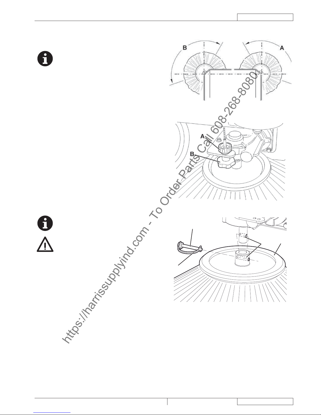
Check the side broom distance from the fl oor, according to 1.
the following procedure:
Drive the machine on a level ground and lower the side •
brooms.
Keep the machine stationary and turn on the side •
brooms for a few seconds.
Lift the side brooms, then move the machine and turn •
it off.
Check that the side broom prints are as shown in the •
fi gure (A and B, Fig. 7).
If the print is not within specifi cations, adjust the broom
height, according to the procedure shown in step 2.
Engage the parking brake.2.
Turn the ignition key (72) to “0”.3.
Loosen the knob (A, Fig. 8) positioned above the broom.4.
Turn the knob (B), and remind that:5.
It must be screwed to lift the broom;•
It must be unscrewed to lower the broom.•
After the adjustment, hold the knob (B) and tighten the
knob (A).
Perform step 1 again to check the proper adjustment of the 6.
side broom height.
When the brooms are too worn and can no longer be 7.
adjusted, replace them according to the procedure shown
in the relevant paragraph.
SIDE BROOM REPLACEMENT
NOTE
Brooms of various hardness are available. This
procedure is applicable to all types of brooms.
CAUTION!
It is advisable to wear protective gloves when
replacing the side brooms because there can be
sharp debris between the bristles.
Drive the machine on a level ground and engage the 1.
parking brake.
Turn the ignition key (82) to “0”.2.
Release the spring (A, Fig. 9), remove the pin (B) and the 3.
broom (C) from the gearmotor shaft.
Install the new broom on the gearmotor shaft, insert the pin 4.
(B) in the holes (D), and engage the spring (A).
Check and adjust the side broom height as shown in the 5.
previous paragraph.
S311394
Figura 7
S311395
Figura 8
A
C
D
B
P100350
Figura 9
https://harrissupplyind.com - To Order Parts Call 608-268-8080
Page 22

ENGLISH
INSTRUCTION FOR USE
20
1464035000(1)2009-06 Terra™ 4300B
DUST FILTER CLEANING AND INTEGRITY
CHECK
NOTE
Besides the standard paper fi lter, polyester fi lters are
also available. The following procedure is applicable
to each type of fi lter.
Drive the machine on a level ground and engage the 1.
parking brake.
Turn the ignition key (72) to “0”.2.
Disengage the hook (18) by pulling its lower end.3.
Remove the hopper (17) by using the handle (19) and by 4.
disengaging it from the inner guides.
Unscrew the knobs (33) and remove the fi lter compartment 5.
cover (32).
Loosen the knobs (A, Fig. 10).6.
Disconnect the fi lter shaker motor (C) electrical connector 7.
(B).
Remove the dust fi lter fastening frame (D).8.
Remove the dust fi lter (E).9.
In an outdoor area, clean the fi lter by shaking it on a level 10.
and clean surface, tapping the side (A, Fig. 11) opposite to
the wire gauze (B).
Complete the cleaning procedure by using compressed
air (C) at maximum 6 Bar, blowing only from the side
protected by the wire gauze (B), at a minimum distance of
12 in (30 cm).
According to the fi lter type, observe the following cautions:
Paper fi lter (standard): Do not use water or detergents •
to clean it, otherwise it can be damaged.
Polyester fi lter (optional): For a better cleaning, it is •
allowed to wash the fi lter with water and non-lathering
detergents. This provides better quality cleaning but
reduces the life of the fi lter, which will have to be
replaced more frequently. Using inadequate detergents
can damage the fi lter.
Check the fi lter body for tears. If necessary, replace the 11.
fi lter.
Clean the rubber gasket (A, Fig. 12) of the cover (32) and 12.
check it for integrity and effi ciency; if necessary replace it.
Assemble the components in the reverse order of 13.
disassembly, and note the following:
Install the fi lter (E, Fig. 10) with the wire gauze (B, Fig. •
11) facing upwards.
B
C
E
A
D
A
S311397
Figura 10
S311399
Figura 11
A
S311398
Figura 12
https://harrissupplyind.com - To Order Parts Call 608-268-8080
Page 23

INSTRUCTION FOR USE
ENGLISH
Terra™ 4300B 1464035000(1)2009-06
21
SKIRT HEIGHT AND OPERATION CHECK
Drive the machine on a level fl oor that is suitable for 1.
checking the skirt height.
Engage the parking brake.2.
Turn the ignition key (72) to “0”.3.
Side skirt check
Unscrew the knobs (23 and 21) and remove both left (20) 1.
and right doors (22).
Check the side skirts (13 and 14) for integrity. Replace the 2.
skirts when they have cuts (A, Fig. 13) larger than 0.8 in
(20 mm) or cracks (B) larger than 0.4 in (10 mm) (for skirt
replacement, refer to the Service Manual).
Check that distance from the ground of the side skirts 3.
(13 and 14) is within 0 - 0.1 in (0 – 3 mm) (A, Fig. 14). If
necessary, adjust the skirt height by using the slots on the
screws (A, Fig. 17).
Assemble the components in the reverse order of 4.
disassembly.
Front and rear skirt check
Remove the main broom as shown in the relevant 1.
paragraph.
Check the front (15) and rear skirts (16) for integrity. 2.
Replace the skirts when they have cuts (A, Fig. 13) larger
than 0.8 in (20 mm) or cracks (B) larger than 0.4 in (10
mm) (for skirt replacement, refer to the Service Manual).
Check that:3.
The front skirt (A, Fig. 18) slightly touches the fl oor (A, •
Fig. 15).
The distance from the ground of the rear skirt (B, Fig. •
18) is within 0 - 0.1 in (0 – 3 mm) (A, Fig. 14).
If necessary, adjust the skirt height by using the slots on 4.
the screws (C and D, Fig. 18).
Press the front skirt lifting pedal (5) and check that the 5.
front skirt (A, Fig. 16) turns upward for about 90° (as
shown in the fi gure); then release the pedal and check
that the skirt does not remain in an intermediate position
but returns to its initial position. If necessary, for the front
skirt control cable adjustment or replacement, refer to the
Service Manual.
Assemble the components in the reverse order of 6.
disassembly.
S311400 S311401
Figura 13 Figura 14
S311402 S311403
Figura 15 Figura 16
A
A
S311404
Figura 17
S311405
Figura 18
https://harrissupplyind.com - To Order Parts Call 608-268-8080
Page 24

ENGLISH
INSTRUCTION FOR USE
22
1464035000(1)2009-06 Terra™ 4300B
BATTERY CHARGING
CAUTION!
Charge the batteries when the yellow (73) or red warning light (74) turns on and at the end of each cleaning
cycle. Keeping the batteries charged make their life last longer.
WARNING!
When the batteries are discharged, charge them as soon as possible, as that condition makes their life shorter.
WARNING!
If the machine is equipped with lead (WET) batteries, battery charging produces highly explosive hydrogen gas.
Charge the batteries in well-ventilated areas and away from naked fl ames.
Do not smoke while charging the batteries.
While charging the batteries always keep the hood open.
WARNING!
Pay careful attention when charging WET batteries as there may be battery fl uid leakages. The battery fl uid is
corrosive. If it comes in contact with skin or eyes, rinse thoroughly with water and consult a physician.
Drive the machine on a level ground and engage the parking brake.1.
Turn the ignition key (72) to “0”.2.
Open the hood (7).3.
(For WET batteries only) check the level of electrolyte inside the batteries. If necessary, top up through the caps (45).4.
Leave all the caps (45) open for battery charging. If necessary, clean the upper surface of the batteries.
Charge the batteries according to one of the following methods, depending on the presence of the electronic battery charger 5.
(47).
Charging the batteries with the battery charger
(For WET batteries only) check the level of electrolyte inside the batteries. If necessary, top up through the caps (45).1.
Leave all the caps (45) open for battery charging.
When the correct level is reached, clean, if necessary, the upper surface of the batteries.
Connect the battery charger cable (48) to the electrical mains.2.
WARNING!
Check that the voltage and frequency shown on the machine serial number plate (37) match the electrical mains
values.
NOTE
When the battery charger is connected to the electrical mains, all machine functions are automatically disabled.
When the green warning light (50) turns on, the batteries are charged.3.
For further information about the battery charger operation (47), see the Battery Charger Manual.4.
Disconnect the battery charger cable (48) from the electrical mains and place it in its housing on the machine.5.
(For WET batteries only) Close all the caps (45).6.
Close the hood (7). The machine is ready to be used.7.
https://harrissupplyind.com - To Order Parts Call 608-268-8080
Page 25

INSTRUCTION FOR USE
ENGLISH
Terra™ 4300B 1464035000(1)2009-06
23
FUSE CHECK/REPLACEMENT/RESET
Drive the machine on a level ground and engage the 1.
parking brake.
Turn the ignition key (72) to “0”.2.
Open the hood (7).3.
Disconnect the battery connector (46).4.
Lamellar fuse check/replacement
Remove the fuse box cover (51).1.
Check/replace the relevant fuse among the following (Fig. 2.
19):
(A): F1 main fuse (key circuit) (15 A)•
(B): F2 fi lter shaker motor fuse (25 A)•
(C): F3 manual vacuum system fuse (40 A) (optional)•
(D): F4 vacuum system motor fuse (30 A)•
(E): F5 horn and pivoting light fuse (10 A)•
(F): F6 working light fuse (10 A) (optional)•
Remove the electrical component box cover (55).3.
Check/replace the following fuse (Fig. 20):4.
FT drive system fuse (70 A)(e):
Fuse check
Check one of the following fuses (Fig. 19) for deactivation:1.
(G): FA main broom motor fuse (30 A)
(H): FB side broom motor fuse (10 A)
Reset any deactivated fuse, when the component that
caused deactivation has fully cooled down.
Close the hood (7).2.
ABCDEF
GH
P100348
Figura 19
A
P100349
Figura 20
SAFETY FUNCTIONS
The machine is equipped with the following safety functions.
EMERGENCY PUSH-BUTTON
It is located in an easily accessible position (82). It has to be pressed in case of emergency, to stop all the machine functions.
DRIVER’S SEAT MICROSWITCH
It is located inside the driver’s seat and it does not allow the machine drive system to operate if the operator is not seated on the
driver’s seat.
https://harrissupplyind.com - To Order Parts Call 608-268-8080
Page 26

ENGLISH
INSTRUCTION FOR USE
24
1464035000(1)2009-06 Terra™ 4300B
TROUBLESHOOTING
Problem Possible cause Remedy
The machine does not start when turning the
ignition key to “I”.
The battery connector is disconnected. Connect the battery connector.
The F1 fuse in the box is open. Replace the fuse.
The battery charger cable is connected to the
electrical mains.
Disconnect the battery charger cable from the
electrical mains.
The machine does not move when pressing
the pedal.
The parking brake is engaged. Disengage the parking brake.
When starting the machine with the ignition key,
the pedal is pressed, or the operator is not yet
on the driver’s seat.
Start the machine with the ignition key, only after
being on the driver’s seat and without pressing
the pedal.
The FT fuse is open. Replace the fuse.
The main broom does not work. The FA fuse is deactivated. Reset the fuse by pressing the relevant switch.
The side brooms do not operate.
The main broom is not lowered. Lower the main broom.
The FB fuse is deactivated. Reset the fuse by pressing the relevant switch.
The machine collects little debris/dust.
The vacuum system is turned off. Turn on the vacuum system with the switch.
The F4 fuse in the box is open. Replace the fuse.
The dust fi lter is clogged.
Clean the dust fi lter by using the fi lter shaker or
by disassembling it.
The hopper is full. Empty the hopper.
The skirts are not properly adjusted or are worn. Adjust/replace the skirts.
The brooms are not properly adjusted. Adjust the broom height.
The fi lter shaker does not operate. The F2 fuse in the box is open. Replace the fuse.
The machine operates only when stationary,
otherwise the red warning light turns on.
The batteries are discharged.
Charge the batteries.
If the problem persists, replace the batteries.
The battery autonomy is low.
The batteries are dead. Replace the batteries.
The battery capacity is low.
Buy batteries with higher capacity (see the
Technical Data paragraph).
The drive system electronic board malfunction
led is fl ashing.
The drive system is malfunctioning.
To detect the failure, refer to the Service Manual
(at any Advance Dealer).
For further information contact a Advance Dealer, where it is possible to consult the Service Manual.
SCRAPPING
Have the machine scrapped by a qualifi ed scrapper.
Before scrapping the machine, remove and separate the following materials, which must be disposed of properly according to the
law in force:
Batteries –
Polyester dust fi lter –
Main and side brooms –
Plastic components –
Electrical and electronic components (*) –
Refer to the nearest Advance Center especially when scrapping electrical and electronic components.(*)
https://harrissupplyind.com - To Order Parts Call 608-268-8080
Page 27

MANUEL D’UTILISATION
FRANÇAIS
Terra™ 4300B 1464035000(1)2009-06
1
TABLE DES MATIERES
INTRODUCTION ..............................................................................................................................................................2
BUT ET CONTENU DU MANUEL ............................................................................................................................... 2
DESTINATAIRES ........................................................................................................................................................ 2
CONSERVATION DU MANUEL .................................................................................................................................. 2
DONNEES D’IDENTIFICATION .................................................................................................................................. 2
AUTRES MANUELS DE REFERENCE ...................................................................................................................... 2
PIECES DE RECHANGE ET ENTRETIEN ................................................................................................................. 3
MODIFICATIONS ET AMELIORATIONS .................................................................................................................... 3
CAPACITES OPERATIONNELLES ............................................................................................................................. 3
CONVENTIONS .......................................................................................................................................................... 3
DEBALLAGE / LIVRAISON ............................................................................................................................................. 3
SECURITE .......................................................................................................................................................................4
SYMBOLES UTILISES ................................................................................................................................................ 4
INSTRUCTIONS GENERALES .................................................................................................................................. 4
DESCRIPTION DE LA MACHINE ...................................................................................................................................6
STRUCTURE DE LA MACHINE ................................................................................................................................. 6
TABLEAU DE BORD ET COMMANDES ..................................................................................................................... 8
ACCESSOIRES / OPTIONS ....................................................................................................................................... 8
CARACTERISTIQUES TECHNIQUES ....................................................................................................................... 9
SCHEMA ELECTRIQUE ........................................................................................................................................... 10
UTILISA TION ................................................................................................................................................................. 12
CONTROLE / PREPARATION DES BATTERIES SUR UNE MACHINE NEUVE ..................................................... 12
CONFIGURATION DU TYPE DE BATTERIES INSTALLEES (WET OU GEL) ......................................................... 13
AVANT LA MISE EN MARCHE ................................................................................................................................. 13
MISE EN MARCHE ET ARRET DE LA MACHINE .................................................................................................... 14
FREIN DE STATIONNEMENT .................................................................................................................................. 14
MACHINE AU TRAVAIL ............................................................................................................................................. 15
VIDANGE DU CONTENEUR DECHETS .................................................................................................................. 15
APRES L’UTILISATION DE LA MACHINE ................................................................................................................ 15
DEPLACEMENT PAR POUSSEE / REMORQUAGE DE LA MACHINE ................................................................... 15
INACTIVITE PROLONGEE DE LA MACHINE .......................................................................................................... 15
PREMIERE PERIODE D’UTILISATION .................................................................................................................... 15
ENTRETIEN ...................................................................................................................................................................16
PLAN D’ENTRETIEN PROGRAMME ....................................................................................................................... 16
CONTROLE ET REGLAGE DE LA HAUTEUR DU BALAI CENTRAL ...................................................................... 17
REMPLACEMENT DU BALAI CENTRAL ................................................................................................................. 18
CONTROLE ET REGLAGE DE LA HAUTEUR DES BALAIS LATERAUX ............................................................... 19
REMPLACEMENT DES BALAIS LATERAUX ........................................................................................................... 19
NETTOYAGE ET CONTROLE DE L’INTEGRITE DU FILTRE A POUSSIERE ......................................................... 20
CONTROLE DE LA HAUTEUR ET DU FONCTIONNEMENT DES VOLETS ........................................................... 21
CHARGEMENT DES BATTERIES ............................................................................................................................ 22
CONTROLE / REMPLACEMENT / RETABLISSEMENT DES FUSIBLES ................................................................ 23
FONCTIONS DE SECURITE ......................................................................................................................................... 23
BOUTON-POUSSOIR D’URGENCE......................................................................................................................... 23
MICROINTERRUPTEUR DU SIEGE DE CONDUITE .............................................................................................. 23
DEPISTAGE DES PANNES ........................................................................................................................................... 24
MISE A LA FERRAILLE .................................................................................................................................................24
https://harrissupplyind.com - To Order Parts Call 608-268-8080
Page 28

FRANÇAIS
MANUEL D’UTILISATION
2
1464035000(1)2009-06 Terra™ 4300B
INTRODUCTION
REMARQUE
Les nombres entre parenthèses se rapportent aux composants indiqués au chapitre Description de la machine.
BUT ET CONTENU DU MANUEL
Ce manuel se propose de fournir à l’opérateur toutes les informations nécessaires afi n qu’il puisse utiliser la machine correctement
et la gérer de la manière la plus autonome et sûre. Il comprend des informations relatives à l’aspect technique, la sécurité, le
fonctionnement, l’arrêt de la machine, l’entretien, les pièces de rechange et la mise à la ferraille.
Avant d’effectuer toute opération sur la machine, les opérateurs et les techniciens qualifi és doivent lire attentivement les instructions
contenues dans ce manuel. En cas de doutes sur la correcte interprétation des instructions, contacter Advance pour avoir plus de
renseignements.
DESTINATAIRES
Ce manuel s’adresse à l’opérateur aussi bien qu’aux techniciens préposés à l’entretien de la machine.
Les opérateurs ne doivent pas exécuter les opérations réservées aux techniciens qualifi és. Advance ne répond pas des dommages
dus à l’inobservance de cette interdiction.
CONSERVATION DU MANUEL
Le manuel d’utilisation doit être gardé près de la machine, dans une enveloppe spéciale et, surtout, loin de liquides et de tout ce qui
pourrait en compromettre l’état de lisibilité.
DONNEES D’IDENTIFICATION
Le numéro de série et le modèle de la machine sont indiqués sur la plaque (37).
L’année de fabrication de la machine est indiquée par les deux premiers chiffres du numéro de série de la machine.
Ces informations sont nécessaires lors de la commande des pièces de rechange de la machine. Utiliser l’espace suivant pour y
noter les données d’identifi cation de la machine.
Modèle de la MACHINE ....................................................................
Numéro de série de la MACHINE ......................................................
AUTRES MANUELS DE REFERENCE
Les manuels suivants sont livrés avec la machine :
Manuel du chargeur de batterie électronique, qui doit être considéré comme une partie intégrante de ce manuel –
Catalogue de pièces de rechange de la balayeuse –
Autres manuels disponibles :
Manuel d’entretien (consultable auprès des Services après-vente Advance) –
https://harrissupplyind.com - To Order Parts Call 608-268-8080
Page 29

MANUEL D’UTILISATION
FRANÇAIS
Terra™ 4300B 1464035000(1)2009-06
3
PIECES DE RECHANGE ET ENTRETIEN
Pour toute nécessité concernant l’emploi, l’entretien et la réparation, s’adresser au personnel qualifi é ou directement aux Services
après-vente Advance. Utiliser toujours des pièces de rechange et des accessoires d’origine.
Pour l’assistance ou la commande de pièces de rechange et accessoires, contacter Advance en spécifi ant toujours le modèle et le
numéro de série de la machine.
MODIFICATIONS ET AMELIORATIONS
Advance vise à un constant perfectionnement de ses produits et se réserve le droit d’effectuer des modifi cations et des
améliorations lorsqu’elle le considère nécessaire sans l’obligation de modifi er les machines précédemment vendues.
Il est entendu que toute modifi cation et / ou addition d’accessoires doit toujours être approuvée et réalisée par Advance.
CAPACITES OPERATIONNELLES
Cette balayeuse est conçue et fabriquée pour le nettoyage / balayage de sols lisses et solides et pour le ramassage de poussières
et déchets légers, en milieux civils et industriels, en condition de complète sécurité par un opérateur qualifi é.
CONVENTIONS
Toutes les références à en avant, en arrière, avant, arrière, droite ou gauche indiquées dans ce manuel doivent être considérées
comme référées à l’opérateur assis en position de conduite sur le siège (25).
DEBALLAGE / LIVRAISON
Pour déballer la machine, suivre attentivement les instructions sur l’emballage.
Lors de la livraison de la machine, contrôler attentivement que l’emballage et la machine n’ont pas été endommagés pendant le
transport. Si les dommages sont évidents, garder l’emballage de façon qu’il puisse être examiné par le transporteur qui l’a livré.
Contacter immédiatement le transporteur pour remplir une demande de dommages-intérêts.
Contrôler que le matériel livré avec la machine correspond à la liste suivante :
Documentation technique : –
Manuel d’utilisation de la balayeuse•
Manuel du chargeur de batterie électronique•
Catalogue de pièces de rechange de la balayeuse•
N° 1 fusible de 70 A –
https://harrissupplyind.com - To Order Parts Call 608-268-8080
Page 30
FRANÇAIS
MANUEL D’UTILISATION
4
1464035000(1)2009-06 Terra™ 4300B
SECURITE
On utilise la symbolique suivante pour signaler les conditions de danger potentielles. Lire attentivement ces informations et prendre
les précautions nécessaires pour protéger les personnes et les choses.
Pour éviter tout accident, la collaboration de l’opérateur est essentielle. Aucun programme de prévention des accidents du travail
ne peut résulter effi cace sans la totale collaboration de la personne directement responsable du fonctionnement de la machine. La
plupart des accidents qui peuvent survenir dans une entreprise, pendant le travail ou les déplacements, sont dus à l’inobservance
des plus simples règles de prudence. Un opérateur attentif et prudent est la meilleure garantie contre les accidents du travail et se
révèle indispensable pour compléter n’importe quel programme de prévention.
SYMBOLES UTILISES
DANGER !
Indique une situation dangereuse exposant l’opérateur au risque de blessures graves, voire mortelles.
ATTENTION !
Indique un risque potentiel d’accident pour les personnes ou de dommage matériel.
AVERTISSEMENT !
Indique un avertissement ou une remarque sur des fonctions clé ou utiles. Prêter la plus grande attention aux
segments de texte marqués par ce symbole.
REMARQUE
Indique une remarque sur des fonctions clé ou utiles.
CONSULTATION
Indique la nécessité de consulter le manuel d’utilisation avant d’effectuer toute opération.
INSTRUCTIONS GENERALES
Les avertissements et précautions spécifi ques suivants informent sur les potentiels risques de dommages à la machine ou aux
personnes.
DANGER !
Avant d’effectuer toute opération de nettoyage de la machine, d’entretien et de remplacement des –
composants, débrancher la batterie, enlever la clé de contact et activer le frein de stationnement.
Cette machine doit être utilisée uniquement par le personnel adéquatement formé. L’utilisation de la –
machine est interdite aux enfants et aux personnes handicapées.
Les manoeuvres de braquage doivent être effectuées à vitesse extrêmement réduite. Eviter de braquer –
brusquement, en particulier en pente.
Ne pas porter de bijoux quand on travaille près des composants électriques. –
Tenir les étincelles, les fl ammes et les matériaux fumants et incandescents loin des batteries. Les batteries –
produisent des gaz potentiellement explosifs pendant l’utilisation ordinaire.
Ne pas travailler sous la machine soulevée, sans des supports fi xes de sécurité convenables. –
Chaque fois qu’on travaille sous le coffre ouvert, s’assurer que celui-ci ne peut pas se refermer –
accidentellement.
Ne pas opérer avec cette machine en présence de poudres, liquides ou vapeurs nuisibles, dangereux, –
infl ammables et / ou explosifs : la machine ne doit pas être utilisée pour ramasser des matériaux
dangereux.
Si des batteries au plomb (WET) sont installées dans la machine, en chargeant les batteries un gaz –
hydrogène très explosif est produit. Garder le coffre ouvert pendant le cycle de rechargement des batteries
et effectuer l’opération exclusivement en milieux bien aérés et loin de fl ammes libres.
En cas d’installation à bord de batteries au plomb (WET), ne pas incliner la machine de plus de 30° depuis –
l’horizontale, car cela pourrait provoquer des pertes de liquide très corrosif. Au cas où il serait nécessaire
d’incliner la machine pour l’entretien, enlever les batteries.
https://harrissupplyind.com - To Order Parts Call 608-268-8080
Page 31

MANUEL D’UTILISATION
FRANÇAIS
Terra™ 4300B 1464035000(1)2009-06
5
ATTENTION !
Avant d’effectuer toute activité d’entretien / réparation, lire attentivement toutes les instructions qui –
concernent l’entretien / réparation.
Prendre les précautions convenables afi n que les cheveux, les bijoux, les parties non adhérentes des –
vêtements ne soient pas capturés par les parties en mouvement de la machine.
Avant d’utiliser le chargeur de batterie, s’assurer que la fréquence et la tension indiquées sur la plaque –
avec numéro de série de la machine coïncident avec la tension du réseau.
Ne pas utiliser le câble du chargeur de batterie pour tirer ou transporter la machine et ne pas utiliser le –
câble comme poignée. Ne pas fermer de porte sur le câble du chargeur de batterie, ne pas tirer le câble sur
des surfaces ou coins tranchants. Ne pas faire passer la machine sur le câble du chargeur de batterie.
Tenir le câble du chargeur de batterie loin des surfaces chaudes. –
Si le câble du chargeur de batterie ou la fi che sont endommagés, ne pas charger les batteries de la –
machine. Si le câble du chargeur de batterie est endommagé, contacter un Service après-vente Advance.
Pour réduire le risque d’incendie, choc électrique ou blessures, ne pas laisser la machine sans surveillance –
lorsqu’elle est branchée au réseau électrique. Débrancher le câble du chargeur de batterie du réseau
électrique avant d’effectuer toute opération d’entretien.
Pour éviter l’utilisation non autorisée de la machine, enlever la clé de contact. –
Avant de laisser la machine sans surveillance, veiller à ce que celle-ci ne puisse pas bouger de façon –
autonome.
Ne pas utiliser la machine sur des surfaces ayant une pente supérieure à la valeur indiquée sur la machine –
même.
Utilisez exclusivement les balais livrées avec la machine et spécifi ées dans le manuel d’utilisation. –
L’utilisation de balais différentes peut compromettre la sécurité.
Avant d’utiliser la machine, fermer tous les couvercles et / ou portillons. –
Ne pas utiliser la machine dans des endroits très poussiéreux. –
Utiliser la machine exclusivement dans des endroits illuminés. –
Si l’on utilise la machine en présence d’autres personnes, il faut activer le feu tournant (optionnel). –
Ne pas laver la machine avec des jets d’eau directs ou sous pression ou avec des substances corrosives. –
Ne pas utiliser d’air comprimé pour le nettoyage général de la machine, sauf que pour les fi ltres (voir le
paragraphe spécifi que).
Pendant l’utilisation de cette machine, faire attention à sauvegarder l’intégrité des autres personnes, en –
particulier des enfants.
Ne pas poser de conteneurs de liquides sur la machine. –
La température de stockage doit être comprise entre 0°C et +40°C. –
La température de travail de la machine doit être comprise entre 0°C et +40°C. –
L’humidité doit être comprise entre 30 % et 95 %. –
Protéger toujours la machine du soleil, de la pluie et d’autres intempéries, pendant le fonctionnement et en –
état d’arrêt. Garder la machine dans un endroit couvert et sec : elle a été conçue pour l’utilisation à sec, par
conséquent elle ne doit pas être utilisée ou gardée dehors, dans des conditions d’humidité.
Ne pas utiliser la machine comme moyen de transport ou de poussée / remorquage. –
Ne pas faire travailler les balais lorsque la machine est arrêtée pour ne pas endommager le sol. –
En cas d’incendie, il est préférable d’utiliser un extincteur à poudre, plutôt qu’un extincteur à eau. –
Ne pas heurter contre des étagères ou des échafaudages, en particulier en cas de danger de chute d’objets. –
Adapter la vitesse d’utilisation aux conditions d’adhérence. –
Éviter tout freinage brusque en descente. Éviter tout changement brusque de direction. Procéder à vitesse –
réduite en descente.
La machine n’est pas approuvée pour l’utilisation sur la voie publique. –
Ne pas altérer pour aucune raison les protections prévues pour la machine.
–
Respecter scrupuleusement les instructions prévues pour l’entretien ordinaire. –
Ne pas enlever ou altérer les plaques installées sur la machine. –
S’assurer que les éventuelles anomalies de fonctionnement de la machine ne dépendent pas du manque –
d’entretien. En cas contraire demander l’intervention de personnel autorisé ou d’un Service après-vente
agréé.
En cas de remplacement de pièces, demander les pièces de rechange D’ORIGINE à un concessionnaire ou –
revendeur agréé.
Afi n de garantir la sécurité et le bon fonctionnement de la machine, faire effectuer l’entretien programmé –
prévu au chapitre spécifi que de ce manuel par du personnel autorisé ou par un Service après-vente agréé.
Lors de la mise à la ferraille, la machine ne doit pas être abandonnée par la présence de matériaux toxiques –
(batteries, huiles, matériaux plastiques, etc.), sujets à des lois qui prévoient l’élimination auprès de centres
spéciaux (voir le chapitre Mise à la ferraille).
https://harrissupplyind.com - To Order Parts Call 608-268-8080
Page 32

FRANÇAIS
MANUEL D’UTILISATION
6
1464035000(1)2009-06 Terra™ 4300B
DESCRIPTION DE LA MACHINE
STRUCTURE DE LA MACHINE
Volant1.
Pédale de marche avant / arrière2.
Pédale frein de service3.
Levier frein de stationnement4.
Appuyer sur la pédale du frein (3) puis actionner le
levier (4) pour commuter le frein de service en frein de
stationnement.
Pédale volet avant5.
Porte-objets6.
Coffre7.
Roues arrière de traction sur essieu fi xe8.
Roue avant de direction9.
Balai latéral droit10.
Balai latéral gauche11.
Balai central12.
Volet latéral gauche13.
Volet latéral droit14.
Volet avant15.
Volet arrière16.
Conteneur déchets (le vider lorsqu’il est plein)17.
Crochet de retenue conteneur déchets18.
Poignée conteneur déchets19.
Portillon gauche (ouvrir seulement pour les opérations 20.
d’entretien)
Pommeaux portillon21.
Portillon gauche (pour enlever le balai central)22.
Pommeaux portillon23.
Feu clignotant (toujours en fonction si la clé de contact est 24.
sur “I”) (optionnel)
Siège de conduite avec microinterrupteur de sécurité25.
Prise supplémentaire pour aspirateur manuel (optionnel)26.
Colonne de direction, inclinable en avant ou en arrière27.
Feu de travail (optionnel)28.
Poignée de réglage hauteur balai latéral droit29.
Poignée de réglage hauteur balai latéral gauche30.
Levier de réglage position longitudinale siège31.
Couvercle compartiment fi ltre d’aspiration32.
Poignées couvercle33.
Aspirateur manuel (optionnel)34.
Dispositifs de retenue aspirateur manuel35.
Conteneurs intérieurs avec poignée pour déchargement 36.
déchets (optionnels)
Plaque avec numéro de série / données techniques / 37.
marquage de conformité
Poignées d’ouverture coffre38.
Ancrages de soulèvement machine39.
36
36
17
17
18
16
12
19
33
32
33
22
23
14
35
34
37
26
35
34
6
7
24
25
1
31
27
2
3
4
5
8
21
20
13
15
11
30
9
28
10
29
38
38
39
39
39
39
8
P100344
https://harrissupplyind.com - To Order Parts Call 608-268-8080
Page 33

MANUEL D’UTILISATION
FRANÇAIS
Terra™ 4300B 1464035000(1)2009-06
7
STRUCTURE DE LA MACHINE (suite)
Coffre (ouvert)41.
Tirants de support coffre42.
Batteries au plomb (WET) ou au gel (GEL) (optionnelles)43.
Schémas de branchement batteries44.
Bouchons batteries (seulement pour batteries WET)45.
Connecteur batteries46.
Chargeur de batterie électronique 47.
Câble chargeur de batterie48.
Sélecteur chargeur de batterie électronique pour batteries 49.
au plomb (WET) ou au gel (GEL)
Témoin lumineux batteries chargées50.
Boîte fusibles à lamelle51.
Fusible restaurable moteur balai central52.
Fusible restaurable moteurs balais latéraux53.
DEL de signalisation système de traction en panne.54.
Si le DEL est allumé fi xe, le système de traction fonctionne
correctement ; si le DEL clignote, le système de traction
est en panne.
Boîte composants électriques55.
Carte électronique système de traction56.
Conteneur batteries57.
Aspirateur manuel (optionnel)58.
Poignée de réglage hauteur balai central59.
Défl ecteur d’air60.
6V
24V
6V
6V 6V
44
41
42
58
55
59
54
53
52
51
46
48
50
49
57
47
43
43
43
42
56
60
43
45
P100345
https://harrissupplyind.com - To Order Parts Call 608-268-8080
Page 34

FRANÇAIS
MANUEL D’UTILISATION
8
1464035000(1)2009-06 Terra™ 4300B
TABLEAU DE BORD ET COMMANDES
Tableau de bord gauche71.
Clé de contact (tournée en position “0”, elle arrête la 72.
machine et en désactive toutes le fonctions ; tournée
en position “I”, elle active toutes le fonctions et le feu
clignotant)
Témoin lumineux batteries déchargées (rouge). S’il 73.
s’allume, il indique que les batteries sont déchargées.
L’autonomie est épuisée et les batteries doivent être
chargées (voir la procédure au paragraphe spécifi que).
Témoin lumineux batteries demi-chargées (jaune). S’il 74.
s’allume, il indique que les batteries sont demi-chargées.
L’autonomie résiduelle est de quelques minutes.
Témoin lumineux batteries chargées (vert). S’il s’allume, 75.
il indique que les batteries sont chargées. L’autonomie
résiduelle dépend de la capacité des batteries installées et
des conditions de travail.
Affi cheur. En y appuyant, on visualise sur l’affi cheur en 76.
séquence :
heures de travail•
dernier chiffre des heures - (point) - minutes•
tension batteries (V)•
Bouton-poussoir de sélection sur l’affi cheur : compteur 77.
horaire/compteur horaire et minuteur/tension batteries (V)
Interrupteur avertisseur sonore78.
Interrupteur ventilateur d’aspiration / secoueur79.
Interrupteur prise supplémentaire pour aspirateur manuel 80.
(optionnelle)
Interrupteur feu de travail (optionnel)81.
Bouton-poussoir d’urgence82.
Il doit être appuyé en cas d’urgence pour arrêter
toute fonction de la machine. Pour le désactiver après
l’utilisation, le tourner dans le sens de la fl èche qui se
trouve sur le bouton-poussoir même.
Vis de fi xation tableaux83.
Tableau de bord droit84.
Levier de soulèvement / abaissement balai latéral droit et 85.
balai latéral gauche
Levier de soulèvement / abaissement balai central86.
Levier de réglage position volant87.
O
F
F
O
N
86
77
73
74
75
76
84
78
85
82
71
79
81
80
83
87
83
72
P100346
ACCESSOIRES / OPTIONS
Outre les composants présents dans le modèle standard, la machine peut être équipée des accessoires optionnels suivants, selon
l’emploi spécifi que de la machine :
Batteries GEL –
Balais central et latéraux avec poils plus ou moins durs par rapport au standard –
Filtre à poussière en polyester antistatique et en polyester BIA C –
Aspirateur manuel –
Feu de travail –
Feu clignotant –
Volets en matériaux différents –
Toit de protection opérateur –
Pour de plus amples informations relatives aux accessoires optionnels susmentionnés, s’adresser au revendeur agréé.
https://harrissupplyind.com - To Order Parts Call 608-268-8080
Page 35

MANUEL D’UTILISATION
FRANÇAIS
Terra™ 4300B 1464035000(1)2009-06
9
TECHNICAL DATA
Caractéristiques générales Valeurs
Longueur machine
58.3 in (1.480 mm)
Largeur machine (sans balais latéraux)
36.6 in (930 mm)
Hauteur maximum machine (au volant)
48.0 in (1.220 mm)
Largeur de nettoyage (sans balais latéraux)
27.6 in (700 mm)
Largeur de nettoyage (avec deux balais latéraux)
49.6 in (1.260 mm)
Hauteur minimum du sol (volets non compris)
2.2 in (55 mm)
Dimensions balai central (diamètre x longueur)
11.8 x 27.6 in (300 mm x 700 mm)
Diamètre balais latéraux
16.5 in (420 mm)
Vitesse de rotation balai central
550 rpm
Vitesse de rotation brosses latérales
80 rpm
Diamètre roue de direction avant
9.8 in (250 mm)
Diamètre roues de traction arrières
9.8 in (250 mm)
Pression spécifi que au sol roue avant
159.5 psi (1.1 N/mm
2
)
Pression spécifi que au sol roues arrière
101.5 psi (0.7 N/mm
2
)
Poids total machine (sans batteries)
573.2 in (260 kg)
Capacité conteneur déchets
18.5 gal (70 Litres)
Moteur balai central
0.67 hp (500 W)
Moteur balais latéraux
0.08 hp (60 W)
Moteur système de traction
0.8 hp (600 W), 110 tr/mn
Moteur système d’aspiration
0.41 hp (310 W)
Moteur secoueur
0.12 hp (90 W), 6.000 tr/mn
Niveau pression acoustique à l’oreille de l’opérateur (ISO 11201, ISO 4871) (LpA)
63,8 ±3 dB(A)
Puissance acoustique émise par la machine (ISO 3744, ISO 4871) (LwA)
84 dB(A)
Niveau de vibrations au bras de l’opérateur (ISO 5349-1) (*)
< 8.2 ft/s
2
(< 2,5 m/s2)
Niveau de vibrations transmises au corps de l’opérateur (ISO 2631-1) (*)
1.9 ft/s
2
(0,6 m/s2)
En conditions de travail normales, sur une surface horizontale d’asphalte.(*)
Performances
Values
Vitesse maximum (marche avant / marche arrière)
3.7 mph (6 km/h)
Vitesse maximum en marche arrière
1.8 mph (3 km/h)
Pente maximum franchissable
11.3° (20 %)
Rayon de braquage minimum
51.6 in (1.310 mm)
Batteries
Values
Tension batteries
24 V
Batterie standard Au plomb, avec électrolyte acide (WET)
Batterie optionnelle Au gel, hermétique (GEL)
Capacité minimum batteries (avec chargeur de batterie)
185 Ah C5
Capacité maximum batteries
256 Ah C5
Dimensions intérieures conteneur batteries (largeur x longueur x hauteur)
24.8 x 16.5 x 14.5 in (630 x 420 x 370 mm)
Dimensions maximum logement batteries (largeur x longueur x hauteur)
26.0 x 17.3 x 16.6 in (660 x 440 x 370 mm)
Aspiration et fi ltrage poussières
Values
Filtre à poussière en papier de 5-10 m
14.1 ft
2
(4,3 m2)
Dépression logement balai central
0.43 in H
2
O (11 mm H2O)
Actionnement secoueur
Electrique
https://harrissupplyind.com - To Order Parts Call 608-268-8080
Page 36

FRANÇAIS
MANUEL D’UTILISATION
10
1464035000(1)2009-06 Terra™ 4300B
SCHEMA ELECTRIQUE
Légende
BAT Batteries
BE1 Feu clignotant (optionnel)
BZ1 Avertisseur sonore de marche arrière / avertisseur sonore
C1 Connecteur batteries
C2 Connecteur secondaire chargeur de batterie
CH1 Chargeur de batterie
EB1 Affi cheur compteur horaire et tension batteries
EB2 Carte électronique système de traction
ES1 Relais balai central
ES2 Relais secoueur
ES3 Relais système d’aspiration
ES4 Relais aspirateur manuel (optionnel)
ES5 Relais balais latéraux
FA Fusible restaurable balai central
FB Fusible restaurable balais latéraux
FT Fusible système de traction (70 A)
F1 Fusible général (circuit clé) (15 A)
F2 Fusible moteur secoueur (25 A)
F3 Fusible aspirateur manuel (40 A) (optionnel)
F4 Fusible moteur système d’aspiration (30 A)
F5 Fusible avertisseur sonore et feu tournant (10 A)
F6 Fusible feu de travail (10 A) (optionnel)
K1 Clé de contact
LD1 DEL diagnostique carte électronique système de traction
L1 Feu de travail (optionnel)
M1 Moteur balai central
M2 Moteur système de traction
M3 Moteur secoueur
M4 Moteur balai latéral droit
M5 Moteur balai latéral gauche
M6 Moteur système d’aspiration
M7 Moteur aspirateur manuel (optionnel)
P1 Interrupteur avertisseur sonore
R1 Potentiomètre vitesse de traction (pédale)
R2 Résistance DEL
SWS Bouton-poussoir d’urgence
SW1 Microinterrupteur balai central
SW2 Interrupteur système d’aspiration / secoueur
SW3 Interrupteur aspirateur manuel (optionnel)
SW4 Microinterrupteur de sécurité dans le siège de conduite
SW5 Microinterrupteur balais latéraux
SW6 Interrupteur feu de travail (optionnel)
Codes des couleurs
BK Noir
BU Bleu clair
BN Marron
GN Vert
GY Gris
OG Orange
PK Rose
RD Rouge
VT Violet
WH Blanc
YE Jaune
https://harrissupplyind.com - To Order Parts Call 608-268-8080
Page 37

MANUEL D’UTILISATION
FRANÇAIS
Terra™ 4300B 1464035000(1)2009-06
11
SCHEMA ELECTRIQUE (suite)
BAT
CH
C1
C1
RDBK
BK
M1
BZ1
ES1
RD
FA
FR
K1
BU
SWS
BU
PK
BK
BE1
SW6
GY
ES1
EB1
BK
L1
GY
F6
BKM4BK
M5
FT
BK
M2
BK
M3
ES2
VT
F2
SW4
BK
M7
ES4
BN
F3
BU
C2
RD
RD
OG
GNBK
GNBK
RD
BU
WH
VT BN
RD
RD
RD
BK
BK
YE
WH
RD
BU
30
87
SW5
BUBK
ES4
BN
SW3
OG
FB
BK
M6
BU
F4
BU
ES3
30
87
OG
SW1
B+
B-
10
1
18
9
M2
M1
EB2
R1
RD
BU
YE
F5
P1
WH
BK
RD
BK
nanc
c
BN
nc
c
RD
ES3
WH
SW2
VT
mom.
ES2
RDBK
GNBK
BK
OG
BN
BU
YEGN
R2
LD1
OG
YEBK
1
2
3
8
7
ES5
30
87
ES5
BK
BUBK
YE
86
85
85
86
85
86
-
+
-
+
R R
S311411
https://harrissupplyind.com - To Order Parts Call 608-268-8080
Page 38

FRANÇAIS
MANUEL D’UTILISATION
12
1464035000(1)2009-06 Terra™ 4300B
UTILISATION
ATTENTION !
Des plaques adhésives appliquées sur certains points de la machine indiquent :
DANGER –
ATTENTION –
AVERTISSEMENT –
CONSULTATION –
Lors de la lecture de ce manuel, l’opérateur doit bien comprendre le sens des symboles illustrés sur les plaques.
Ne pas couvrir les plaques et les remplacer immédiatement en cas d’endommagement.
CONTROLE / PREPARATION DES BATTERIES SUR UNE MACHINE NEUVE
ATTENTION !
Dans le cas où la machine est déplacée par poussée pour des raisons de service (manque de batteries, batteries
déchargées, etc.) ne jamais dépasser la vitesse de 4 km/h (2,5 mph).
REMARQUE
Avec chargeur de batterie à bord, il faut le brancher aux batteries pour permettre le fonctionnement de la machine.
La machine requiert quatre batteries de 6 V, branchées en suivant le schéma (44), ou un boîtier de batteries de 24 V.
La machine peut être livrée selon une des confi gurations suivantes :
Batteries (WET ou GEL) installées dans la machine et prêtes à l’utilisationcj)
Batteries (WET) installées dans la machine, mais sèches, c’est-à-dire sans électrolyte liquideck)
Sans batteriescl)
Selon la confi guration, procéder comme suit.
Batteries (WET ou GEL) installées dans la machine et prêtes à l’utilisationa)
Ouvrir le coffre (7) de la machine et vérifi er que les batteries sont branchées à la machine au moyen du connecteur (46).1.
Fermer le coffre (7).2.
Insérer la clé de contact (72) et la tourner sur “I” [sans appuyer sur la pédale (2)].3.
Si le témoin lumineux vert (75) s’allume, les batteries sont prêtes à l’utilisation.
Si le témoin lumineux jaune (74) ou le témoin lumineux rouge (73) s’allume, il est nécessaire de charger les batteries (voir
la procédure au chapitre Entretien).
Batteries (WET) installées dans la machine, mais sèches, c’est-à-dire sans électrolyte liquideb)
Ouvrir le coffre (7) de la machine.1.
Enlever tous les bouchons (45) des batteries.2.
ATTENTION !
L’acide sulfurique est hautement corrosif, donc le manipuler avec précaution. En cas de contact avec les yeux
ou la peau, laver et rincer abondamment à l’eau et consulter un médecin.
Les batteries doivent être remplies dans un endroit bien aéré.
Porter des gants de protection.
Remplir les éléments des batteries avec acide sulfurique pour batteries ([densité 2.79 à 2.84 lb à 77°F (1.27 à 1.29 kg à 3.
25°C)] selon les instructions spécifi ées dans le manuel des batteries.
La quantité correcte de solution acide à insérer est indiquée dans le manuel des batteries.
Laisser les batteries au repos et remplir les éléments avec la solution d’acide sulfurique, selon les instructions indiquées 4.
dans le manuel des batteries.
Charger les batteries (voir la procédure au chapitre Entretien).5.
Sans batteriesc)
Acheter des batteries adéquates [voir le chapitre Caractéristiques techniques et le schéma (44)].1.
S’adresser aux revendeurs de batteries qualifi és pour le choix et l’installation.
Installer les batteries.2.
Confi gurer la machine et le chargeur de batterie en fonction du type de batteries installées, en suivant les indications du 3.
paragraphe suivant.
https://harrissupplyind.com - To Order Parts Call 608-268-8080
Page 39

MANUEL D’UTILISATION
FRANÇAIS
Terra™ 4300B 1464035000(1)2009-06
13
CONFIGURATION DU TYPE DE BATTERIES INSTALLEES (WET OU GEL)
REMARQUE
Avec chargeur de batterie à bord, il faut le brancher aux batteries pour permettre le fonctionnement de la machine.
En fonction du type de batteries installées (WET ou GEL), confi gurer la carte électronique de la machine et le chargeur de batterie
en procédant comme suit :
Tourner la clé de contact (72) sur “0”.1.
Ouvrir le coffre (7).2.
Confi guration de la machine
La confi guration d’usine de la machine est pour batteries au plomb (WET). Si cette confi guration correspond au type de 1.
batteries achetées, passer au paragraphe suivant. En cas contraire, effectuer les opérations suivantes :
Débrancher le connecteur (46) des batteries.•
Déposer les vis (83) et le tableau de bord droit (84) avec soin.•
Positionner la barrette (A, Fig. 1) sur les connecteurs “GEL” (B) pour batteries au gel.•
Installer avec soin le tableau de bord (84) et le fi xer à l’aide des vis.•
Brancher le connecteur (46) des batteries.•
C
B
A
S311412
Figure 1
Confi guration du chargeur de batterie
Positionner le sélecteur (49) sur WET pour batteries au plomb ou sur GEL pour batteries au gel.1.
Charger les batteries (voir la procédure au chapitre Entretien).2.
AVANT LA MISE EN MARCHE
AVERTISSEMENT !
S’assurer que la machine n’a pas de portillons / coffres ouverts et qu’elle se trouve dans des conditions
normales d’utilisation.
S’assurer que le conteneur déchets (17) est fermé correctement.
Si la machine n’a pas encore été utilisée après le transport, vérifi er que tous les sabots et les moyens de
blocage utilisés pour le transport ont été enlevés.
https://harrissupplyind.com - To Order Parts Call 608-268-8080
Page 40

FRANÇAIS
MANUEL D’UTILISATION
14
1464035000(1)2009-06 Terra™ 4300B
MISE EN MARCHE ET ARRET DE LA MACHINE
Mise en marche de la machine
S’asseoir en position de conduite sur le siège (25).1.
Si besoin est, régler la position du siège selon son propre confort à l’aide du levier (31).2.
Si besoin est, régler l’inclinaison, en avant ou en arrière, de la colonne de direction (1) selon son propre confort à l’aide du
levier (87).
Tourner la clé de contact (72) sur “I”, sans appuyer sur la pédale de marche (2). Vérifi er que le témoin lumineux vert (75) 3.
s’allume (batterie chargée).
Dans le cas où le témoin lumineux jaune (74) ou rouge (73) s’allume, positionner la clé de contact à nouveau sur “0”, puis
charger les batteries (voir la procédure au chapitre Entretien).
Désactiver le frein de stationnement4.
Se porter sur le lieu de travail, démarrer la machine les mains sur le volant et appuyer sur la partie avant de la pédale (2) pour 5.
la marche avant et sur la partie arrière pour la marche arrière.
La vitesse d’avance est réglable de 0 à la valeur maximum, selon la pression exercée sur la pédale (2).
REMARQUE
Le siège (25) est équipé d’un capteur de sécurité qui ne permet le mouvement de la machine, à l’aide de la pédale (2),
que lorsque l’opérateur est assis sur son siège.
Baisser le balai central au moyen du levier (86) ; le balai commencera aussi à tourner.6.
Activer le système d’aspiration en appuyant sur la partie inférieure de l’interrupteur (79).7.
REMARQUE
Le système d’aspiration peut être activé seulement si le balai central est baissé.
Baisser les balais latéraux (10 et 11) à l’aide du levier (85).8.
REMARQUE
Les balais latéraux (10 et 11) peuvent être baissés et soulevés même lorsque la machine est en mouvement.
Les balais latéraux ne tournent pas s’ils sont soulevés ; en outre, ils ne tournent pas si le balai central est soulevé.
Commencer le travail de balayage en manœuvrant le volant (1) et en appuyant sur la pédale (2) pour faire avancer la 9.
machine.
Arrêt de la machine
Pour arrêter la machine, relâcher la pédale (2).1.
Pour arrêter la machine rapidement, appuyer aussi sur la pédale du frein de service (3).
Pour arrêter la machine immédiatement en cas d’urgence, appuyer sur le bouton-poussoir d’urgence (82). Pour désactiver le
bouton-poussoir d’urgence (82) après son activation, le tourner dans le sens de la fl èche qui se trouve sur le bouton-poussoir
même.
Soulever les balais latéraux (10 et 11) à l’aide du levier (85).2.
Désactiver le système d’aspiration en reportant l’interrupteur (79) dans la position initiale.3.
Soulever le balai central (12) à l’aide du levier (86).4.
Pour arrêter la machine, tourner la clé de contact (72) sur “0”.5.
Activer le frein de stationnement.6.
FREIN DE STATIONNEMENT
Activer le frein de stationnement en appuyant sur la pédale (3) et en actionnant le levier (4).1.
Désactiver le frein de stationnement en appuyant sur la pédale (3) et en la relâchant.2.
ATTENTION !
Avant d’effectuer toute opération d’entretien et de remplacement des composants, activer le frein de
stationnement.
Activer le frein de stationnement lorsqu’on stationne la machine en pente ou dans une descente.
https://harrissupplyind.com - To Order Parts Call 608-268-8080
Page 41

MANUEL D’UTILISATION
FRANÇAIS
Terra™ 4300B 1464035000(1)2009-06
15
MACHINE AU TRAVAIL
ATTENTION !
Faire attention lorsqu’on utilise la machine à vitesse élevée, puisque des braquages soudains pourraient
provoquer des situations d’instabilité dues à la typologie de la machine, à trois roues, et à la distribution du
poids sur ces dernières.
Réduire toujours la vitesse avant d’effectuer tout braquage.
Ne pas s’arrêter pendant longtemps dans la même position avec les balais qui tournent : des traces non désirées pourraient 1.
rester sur le sol.
Pour collecter les déchets légers et volumineux, soulever le volet avant en appuyant sur la pédale (5) ; considérer que, 2.
pendant que le volet avant est soulevé, la capacité d’aspiration de la machine est réduite.
AVERTISSEMENT !
S’il est nécessaire d’opérer sur un sol mouillé, il faut désactiver le système d’aspiration au moyen de
l’interrupteur (79) pour protéger le fi ltre à poussière.
Pour un bon travail de balayage il faut que le fi ltre à poussière soit le plus propre possible. Pour le nettoyage du fi ltre pendant 3.
le balayage, activer le secoueur en appuyant sur la partie supérieure de l’interrupteur (79) pendant quelques secondes.
Pendant cette opération, le ventilateur d’aspiration est automatiquement désactivé.
Le nettoyage du fi ltre effectué, appuyer sur la partie inférieure de l’interrupteur (79) pour activer à nouveau le système
d’aspiration, puis reprendre le travail de balayage.
Répéter l’opération en moyenne toutes les 10 minutes pendant le travail (selon la quantité de poussière du milieu à nettoyer).
REMARQUE
Lorsque le fi ltre à poussière est obstrué et / ou le conteneur déchets est plein, la machine n’arrive plus à collecter ni de
poussière ni de déchets.
Vider le conteneur déchets (17) chaque fois qu’il est plein ainsi qu’à la fi n du travail (voir la procédure au paragraphe suivant).4.
VIDANGE DU CONTENEUR DECHETS
Arrêter la machine, en relâchant la pédale de marche.1.
Tourner la clé de contact (72) sur “0”.2.
Activer le frein de stationnement.3.
Dégager le crochet (18) en tirant son extrémité inférieure.4.
Enlever le conteneur déchets (17) à l’aide de la poignée (19), en le dégageant des guides internes.5.
Décharger les déchets dans les conteneurs prévus à cet effet. Le conteneur déchets peut être équipé à son intérieur avec
deux conteneurs (optionnels) avec poignée (36), pour faciliter le déchargement des déchets.
Installer à nouveau les conteneurs avec poignée (36), si présents.6.
Installer le conteneur déchets (17) en l’engageant aux guides internes, puis le fi xer à l’aide du crochet (18).7.
La machine est prête pour reprendre le travail de balayage.8.
APRES L’UTILISATION DE LA MACHINE
Le travail effectué, avant de laisser la machine, d’effectuer les opérations suivantes :
Soulever les balais latéraux à l’aide du levier (85).1.
Soulever le balai central au moyen du levier (86).2.
Activer le secoueur à l’aide de l’interrupteur (79).3.
Vider le conteneur déchets (17) (voir la procédure au paragraphe précédent).4.
Enlever la clé de contact (72).5.
Activer le frein de stationnement.6.
DEPLACEMENT PAR POUSSEE / REMORQUAGE DE LA MACHINE
Pour déplacer aisément la machine par poussée / remorquage, aucun arrangement préalable n’est nécessaire.
INACTIVITE PROLONGEE DE LA MACHINE
Si l’on prévoit de ne pas utiliser la machine pendant plus de 30 jours, il est convenable d’effectuer les opérations suivantes :
S’assurer de garder la machine dans un endroit sec et propre.1.
Débrancher le connecteur (46) des batteries.2.
PREMIERE PERIODE D’UTILISATION
Après la première période d’utilisation (les 8 premières heures), il faut :
Contrôler le serrage des éléments de fi xation et de connexion. –
Vérifi er que les parties visibles sont intactes et qu’elles ne présentent pas de pertes de liquides. –
https://harrissupplyind.com - To Order Parts Call 608-268-8080
Page 42

FRANÇAIS
MANUEL D’UTILISATION
16
1464035000(1)2009-06 Terra™ 4300B
ENTRETIEN
La durée de vie de la machine et sa sécurité de fonctionnement sont garanties par un entretien soigné et régulier.
Veuillez trouver ci-dessous le plan d’entretien programmé. Les périodicités indiquées peuvent subir des variations en fonction de
conditions de travail particulières, à défi nir par le responsable de l’entretien.
Toutes les opérations d’entretien programmé ou extraordinaire doivent être effectuées par du personnel qualifi é ou par un Service
après-vente agréé.
Après le plan d’entretien programmé, ce manuel contient seulement les opérations d’entretien les plus simples et les plus
récurrentes.
Pour les procédures des autres opérations d’entretien prévues par le plan d’entretien programmé et d’entretien extraordinaire, se
référer au manuel d’entretien consultable auprès des Services après-vente.
ATTENTION !
Les opérations d’entretien doivent être effectuées avec la machine arrêtée, la clé enlevée et, le cas échéant, avec
les batteries débranchées.
Lire attentivement toutes les instructions du chapitre Sécurité avant d’effectuer les opérations d’entretien.
PLAN D’ENTRETIEN PROGRAMME
Procédure
Lors de la
livraison
Toutes
les 10
heures
Toutes
les 50
heures
Toutes
les 100
heures
Toutes
les 200
heures
Toutes
les 400
heures
Contrôle niveau liquide batteries WET
Contrôle et réglage de la hauteur des balais latéraux et central
Nettoyage et contrôle de l’intégrité du fi ltre à poussière
Contrôle de la hauteur et du fonctionnement des volets
Contrôle du fonctionnement du secoueur (*)
Contrôle visuel courroie de transmission balai central (*)
Contrôle du serrage des écrous et des vis (*)(1)
Contrôle et réglage frein de service et frein de stationnement (*)
Contrôle et nettoyage chaîne direction (*)
Remplacement courroie de transmission balai central (*)
Contrôle ou remplacement charbons moteur principal et moteur
système de traction
(*)
Pour la procédure relative, se référer au manuel d’entretien.(*)
Et après les 8 premières heures de rodage.(1)
https://harrissupplyind.com - To Order Parts Call 608-268-8080
Page 43

MANUEL D’UTILISATION
FRANÇAIS
Terra™ 4300B 1464035000(1)2009-06
17
CONTROLE ET REGLAGE DE LA HAUTEUR DU
BALAI CENTRAL
REMARQUE
La machine est livrée avec des balais de dureté
différente. La procédure ci-décrite est applicable à
tous les types de balais.
Contrôler la hauteur du sol du balai central, en procédant 1.
comme suit :
Amener la machine sur un sol plat.•
En gardant la machine en position d’arrêt, baisser •
le balai central et le faire tourner pendant quelques
secondes.
Arrêter et soulever le balai central, puis déplacer la •
machine et l’arrêter.
Contrôler que la largeur de la trace (A, Fig. 2) laissée •
par le balai central est comprise entre 0.8 et 1.6 in (2 et
4 cm) dans toute sa longueur.
Au cas où la trace (A) résulterait différente, procéder au
réglage de la hauteur du balai, en opérant comme indiqué
à partir du point 2.
Activer le frein de stationnement.2.
Tourner la clé de contact (72) sur “0”.3.
Ouvrir le coffre (7).4.
Desserrer le pommeau (A, Fig. 3) sur le côté gauche de la 5.
machine.
Tourner le pommeau (B), en considérant que :6.
pour soulever le balai, il doit être vissé ;•
pour baisser le balai, il doit être dévissé.•
Le réglage effectué, serrer le pommeau (A) en bloquant le
pommeau (B).
Exécuter à nouveau le point 1 pour vérifi er le réglage de la 7.
hauteur du sol du balai central.
Lorsque l’usure excessive du balai n’en permet plus 8.
le réglage, le remplacer comme prévu au paragraphe
suivant.
AVERTISSEMENT !
Une trace excessive [supérieure à 1.6 in (4
cm)], de la brosse centrale compromet le
fonctionnement régulier de la machine et
peut provoquer la surchauffe des parties en
mouvement, en réduisant considérablement leur
durée.
Prêter attention pendant l’opération de contrôle
susmentionnée et ne pas faire fonctionner la
machine en conditions différentes de celles
décrites.
A
2 - 4 cm
0,8 - 1,6 in
S311389
Figura 2
A
B
S311390
Figura 3
https://harrissupplyind.com - To Order Parts Call 608-268-8080
Page 44

FRANÇAIS
MANUEL D’UTILISATION
18
1464035000(1)2009-06 Terra™ 4300B
REMPLACEMENT DU BALAI CENTRAL
REMARQUE
La machine est livrée avec des balais de dureté
différente. La procédure ci-décrite est applicable à
tous les types de balais.
AVERTISSEMENT !
L’utilisation de gants de travail est conseillée
pendant le remplacement du balai central à cause
de la présence éventuelle de débris tranchants
parmi les poils.
Porter la machine sur un sol plat e activer le frein de 1.
stationnement.
Tourner la clé de contact (72) sur “0”.2.
Dévisser les pommeaux (23) et enlever le portillon droit 3.
(22).
Dévisser le pommeau (A, Fig. 4).4.
Dévisser les pommeaux (B, Fig. 4) et enlever le couvercle 5.
du logement (C) du balai.
Enlever le balai (A, Fig. 5).6.
Contrôler que le moyeu entraîneur (A, Fig. 6) est propre et 7.
non obstrué par des objets (cordes, chiffons, etc.) enroulés
accidentellement.
Installer le nouveau balai central, en orientant les poils (B) 8.
comme indiqué dans la fi gure.
Installer le nouveau balai central (C, Fig. 6) dans la 9.
machine et s’assurer que sa prise (D) s’insère dans le
relatif moyeu entraîneur (A).
Installer le couvercle du logement (C, Fig. 4) du balai et 10.
visser les pommeaux (B) et (A).
Installer le portillon droit (22) et serrer les pommeaux (23).11.
Contrôler et régler la hauteur du balai central, comme 12.
indiqué au paragraphe précédent.
A
C
B
B
S311391
Figura 4
S311392
Figura 5
S311393
Figura 6
https://harrissupplyind.com - To Order Parts Call 608-268-8080
Page 45

MANUEL D’UTILISATION
FRANÇAIS
Terra™ 4300B 1464035000(1)2009-06
19
CONTROLE ET REGLAGE DE LA HAUTEUR DES
BALAIS LATERAUX
REMARQUE
La machine est livrée avec des balais de dureté
différente. La procédure ci-décrite est applicable à
tous les types de balais.
Contrôler la hauteur du sol des brosses latérales, en 1.
procédant comme suit :
Porter la machine sur un sol plat et baisser les balais •
latéraux.
En gardant la machine en position d’arrêt, faire tourner •
les balais latéraux pendant quelques secondes.
Soulever les balais latéraux, puis déplacer la machine •
et l’arrêter.
Contrôler que les traces laissées par les balais latéraux •
sont, en extension et orientation, comme indiqué dans
la fi gure (A et B, Fig. 7).
Au cas où la trace résulterait différente, procéder au
réglage de la hauteur des balais, en procédant comme
indiqué à partir du point 2.
Activer le frein de stationnement.2.
Tourner la clé de contact (72) sur “0”.3.
Desserrer le pommeau (A, Fig. 8) situé sur le balai.4.
Tourner le pommeau (B), en considérant que :5.
pour soulever le balai, il doit être vissé ;•
pour baisser le balai, il doit être dévissé.•
Le réglage effectué, serrer le pommeau (A) en bloquant le
pommeau (B).
Exécuter à nouveau le point 1 pour vérifi er le réglage de la 6.
hauteur des brosses latérales du sol.
Lorsque l’usure excessive des balais n’en permet plus 7.
le réglage, les remplacer comme prévu au paragraphe
spécifi que.
REMPLACEMENT DES BALAIS LATERAUX
REMARQUE
La machine est livrée avec des balais de dureté
différente. La procédure ci-décrite est applicable à
tous les types de balais.
AVERTISSEMENT !
L’utilisation de gants de travail est conseillée
pendant le remplacement des brosses latérales
à cause de la présence éventuelle de débris
tranchants parmi les poils.
Porter la machine sur un sol plat e activer le frein de 1.
stationnement.
Tourner la clé de contact (82) sur “0”.2.
Dégager le dispositif de fi xation (A, Fig. 9), extraire 3.
le goujon (B) et enlever le balai (C) de l’arbre du
motoréducteur.
Monter le nouveau balai sur l’arbre du motoréducteur, 4.
insérer le goujon (B) dans les trous (D), puis accrocher le
dispositif de fi xation (A).
Contrôler et régler la hauteur des balais latéraux, comme 5.
indiqué au paragraphe précédent.
S311394
Figura 7
S311395
Figura 8
A
C
D
B
P100350
Figura 9
https://harrissupplyind.com - To Order Parts Call 608-268-8080
Page 46

FRANÇAIS
MANUEL D’UTILISATION
20
1464035000(1)2009-06 Terra™ 4300B
NETTOYAGE ET CONTROLE DE L’INTEGRITE
DU FILTRE A POUSSIERE
REMARQUE
Outre le fi ltre en papier standard, des fi ltres en
polyester sont à disposition en tant qu’accessoires
optionnels. La procédure ci-décrite est applicable à
chacun de ces types.
Porter la machine sur un sol plat e activer le frein de 1.
stationnement.
Tourner la clé de contact (72) sur “0”.2.
Dégager le crochet (18) en tirant son extrémité inférieure.3.
Enlever le conteneur déchets (17) à l’aide de la poignée 4.
(19), en le dégageant des guides internes.
Dévisser les pommeaux (33) et enlever le couvercle (32) 5.
du compartiment du fi ltre.
Dévisser les pommeaux (A, Fig. 10).6.
Débrancher le connecteur électrique (B) du moteur (C) du 7.
secoueur.
Enlever le cadre de fi xation (D) du fi ltre à poussière.8.
Déposer le fi ltre à poussière (E).9.
A l’extérieur, dans un endroit approprié, nettoyer le fi ltre 10.
en le secouant sur une surface horizontale et propre, en
battant le côté (A, Fig. 11) opposé à celui du tamis (B).
Compléter le nettoyage à l’aide d’un jet perpendiculaire
d’air comprimé (C) (6 bars maximum), en souffl ant
uniquement du côté protégé par le tamis (B) d’une
distance minimum de 12 in (30 cm).
Observer en outre les indications suivantes en fonction du
fi ltre traité :
Filtre en papier (standard) : ne pas le nettoyer avec •
de l’eau ou du détergent pour ne pas risquer de
l’endommager irrémédiablement.
Filtre en polyester (optionnel) : pour un nettoyage plus •
profond, il est possible de laver le fi ltre avec de l’eau et,
éventuellement, avec des détergents non moussants.
Ce type de lavage, même s’il est meilleur du point de
vue qualitatif, réduit la vie utile du fi ltre, lequel devra
être remplacé plus souvent. L’utilisation de détergents
pas adéquats peut compromettre les caractéristiques
fonctionnelles du fi ltre.
Contrôler que le corps du fi ltre n’a pas de déchirures. Si 11.
besoin est, remplacer le fi ltre.
Nettoyer la bague en caoutchouc (A, Fig. 12) du couvercle 12.
(32) et contrôler qu’elle est intacte et effi cace ; en cas
contraire, la remplacer.
Pour la repose, procéder dans l’ordre inverse de la 13.
dépose, en faisant attention aux indications suivantes :
Installer le fi ltre (E, Fig. 10) avec le tamis (B, Fig. 11) •
tourné vers le haut.
B
C
E
A
D
A
S311397
Figura 10
S311399
Figura 11
A
S311398
Figura 12
https://harrissupplyind.com - To Order Parts Call 608-268-8080
Page 47

MANUEL D’UTILISATION
FRANÇAIS
Terra™ 4300B 1464035000(1)2009-06
21
CONTROLE DE LA HAUTEUR ET DU
FONCTIONNEMENT DES VOLETS
Amener la machine sur un sol plat et adéquat en tant que 1.
plan de référence pour le contrôle de la hauteur des volets.
Activer le frein de stationnement.2.
Tourner la clé de contact (72) sur “0”.3.
Contrôle des volets latéraux
Dévisser les pommeaux (23) et (21) et enlever les 1.
portillons droit (22) et gauche (20).
Contrôler l’intégrité des volets latéraux (13 et 14). 2.
Remplacer les volets en présence de coupures (A, Fig.
13) supérieures à 0.8 in (20 mm) ou de déchirures (B)
supérieures à 10 mm (pour le remplacement des volets, se
référer au Manuel d’entretien).
Contrôler que la hauteur du sol des volets latéraux (13 et 3.
14) est comprise entre 0 et 0.1 in (0 et 3 mm) (A, Fig. 14).
Si besoin est, régler la hauteur des volets en utilisant les
orifi ces oblongs sur les vis (A, Fig. 17).
Pour la repose, procéder dans l’ordre inverse de la 4.
dépose.
Contrôle des volets avant et arrière
Enlever le balai central, comme indiqué au paragraphe 1.
spécifi que.
Contrôler l’intégrité des volets avant (15) et arrière (16). 2.
Remplacer les volets en présence de coupures (A, Fig.
13) supérieures à 0.8 in (20 mm) ou de déchirures (B)
supérieures à 10 mm (pour le remplacement des volets, se
référer au Manuel d’entretien).
Contrôler que :3.
le volet avant (A, Fig. 18) touche légèrement le sol et •
que, de toute façon, il ne se détache pas du sol (A, Fig.
15).
le volet arrière (B, Fig. 18) se trouve à une hauteur du •
sol comprise entre 0 et 0.1 in (0 et 3 mm) (A, Fig. 14).
Si besoin est, régler la hauteur des volets en utilisant les 4.
orifi ces oblongs sur les vis (C et D, Fig. 18).
Appuyer sur la pédale du volet avant (5) et contrôler que 5.
le volet avant (A, Fig. 16) tourne vers le haut d’environ 90°
(voir la fi gure) ; relâcher la pédale et contrôler que le volet
revient à la position initiale et qu’il ne reste pas dans une
position intermédiaire. Si besoin est, pour le réglage ou le
remplacement du câble de commande du volet avant, se
référer au manuel d’entretien.
Pour la repose, procéder dans l’ordre inverse de la 6.
dépose.
S311400 S311401
Figura 13 Figura 14
S311402 S311403
Figura 15 Figura 16
A
A
S311404
Figura 17
S311405
Figura 18
https://harrissupplyind.com - To Order Parts Call 608-268-8080
Page 48

FRANÇAIS
MANUEL D’UTILISATION
22
1464035000(1)2009-06 Terra™ 4300B
CHARGEMENT DES BATTERIES
AVERTISSEMENT !
Charger les batteries lorsque le témoin lumineux jaune (73) ou rouge (74) s’allume, ou à la fi n de chaque cycle
de nettoyage. Garder les batteries chargées prolonge leur vie.
ATTENTION !
Lorsque les batteries sont déchargées, les recharger dès que possible ; dans le cas contraire, leur durée de vie
utile sera réduite.
ATTENTION !
Si des batteries au plomb (WET) sont installées dans la machine, en chargeant les batteries un gaz hydrogène
très explosif est produit. Charger les batteries dans un endroit bien aéré et loin de fl ammes libres.
Ne pas fumer pendant le chargement des batteries.
Garder le coffre ouvert pendant tout le cycle de rechargement des batteries.
ATTENTION !
Pendant le chargement des batteries WET, prêter attention à d’éventuelles sorties de liquide des batteries. Ce
liquide est hautement corrosif. En cas de contact avec les yeux ou la peau, laver et rincer abondamment à l’eau
et consulter un médecin.
Porter la machine sur un sol plat e activer le frein de stationnement.1.
Tourner la clé de contact (72) sur “0”.2.
Ouvrir le coffre (7).3.
(Uniquement pour batteries WET) contrôler le niveau de l’électrolyte dans les batteries. Si besoin est, faire l’appoint au moyen 4.
des bouchons (45).
Laisser tous les bouchons (45) ouverts pour le rechargement successif. Si besoin est, nettoyer la surface supérieure des
batteries.
Charger les batteries selon une des procédures suivantes, en fonction de la présence ou absence, dans la machine, du 5.
chargeur de batterie électronique (47).
Chargement des batteries avec chargeur de batterie
(Uniquement pour batteries WET) contrôler le niveau de l’électrolyte dans les batteries. Si besoin est, faire l’appoint au moyen 1.
des bouchons (45).
Laisser tous les bouchons (45) ouverts pour le rechargement successif.
Après l’appoint du niveau, si besoin est, nettoyer la surface supérieure des batteries.
Brancher le câble (48) du chargeur de batterie à une prise de courant.2.
ATTENTION !
Contrôler que la tension et la fréquence indiquées sur la plaque (37) avec numéro de série de la machine
coïncident avec les valeurs du réseau électrique.
REMARQUE
Lorsque le chargeur de batterie est branché au réseau électrique, toutes les fonctions de la machine sont
automatiquement exclues.
Lorsque le témoin lumineux vert (50) s’allume, les batteries sont chargées.3.
Pour de plus amples informations relatives au fonctionnement du chargeur de batterie (47), se référer au manuel du chargeur 4.
de batterie.
Débrancher le câble (48) du chargeur de batterie du réseau électrique et le remiser dans le logement de la machine.5.
(Uniquement pour batteries WET) fermer tous les bouchons (45).6.
Fermer le coffre (7). La machine est prête à l’utilisation.7.
https://harrissupplyind.com - To Order Parts Call 608-268-8080
Page 49

MANUEL D’UTILISATION
FRANÇAIS
Terra™ 4300B 1464035000(1)2009-06
23
CONTROLE / REMPLACEMENT /
RETABLISSEMENT DES FUSIBLES
Porter la machine sur un sol plat e activer le frein de 1.
stationnement.
Tourner la clé de contact (72) sur “0”.2.
Ouvrir le coffre (7).3.
Débrancher le connecteur (46) des batteries.4.
Contrôle / remplacement des fusibles à lamelle
Enlever le couvercle de la boîte à fusibles (51).1.
Contrôler / remplacer le fusible concerné parmi les 2.
suivants (Fig. 19) :
(A): Fusible général F1 (15 A) (circuit clé)•
(B): Fusible F2 (25 A) moteur secoueur•
(C): Fusible F3 (40 A) aspirateur manuel (optionnel)•
(D): Fusible F4 (30 A) moteur système d’aspiration•
(E): Fusible F5 (10 A) avertisseur sonore et feu •
tournant
(F): Fusible F6 (10 A) feu de travail (optionnel)•
Enlever le couvercle de la boîte des composants 3.
électriques (55).
Contrôler / remplacer le fusible suivant (Fig. 20) :4.
Fusible FT (70 A) système de traction(e):
Contrôle des fusibles restaurables
Contrôler si le fusible concerné parmi les suivants (Fig. 19) 1.
est déclenché :
(G): Fusible FA (30 A) moteur balai central
(H): Fusible FB (10 A) moteurs balais latéraux
Restaurer le fusible déclenché après le refroidissement du
composant qui a provoqué le déclenchement.
Fermer le coffre (7).2.
ABCDEF
GH
P100348
Figura 19
A
P100349
Figura 20
FONCTIONS DE SECURITE
La machine est équipée des fonctions de sécurité décrites ci-dessous.
BOUTON-POUSSOIR D’URGENCE
Il est placé dans une position (82) facilement accessible par l’opérateur. Il doit être appuyé en cas de nécessité urgente pour arrêter
toute fonction de la machine.
MICROINTERRUPTEUR DU SIEGE DE CONDUITE
Il est situé à l’intérieur du siège de conduite et il ne permet le fonctionnement du système de traction de la machine que lorsque
l’opérateur est assis dans son siège.
https://harrissupplyind.com - To Order Parts Call 608-268-8080
Page 50

FRANÇAIS
MANUEL D’UTILISATION
24
1464035000(1)2009-06 Terra™ 4300B
DEPISTAGE DES PANNES
Problème Cause probable Remède
En positionnant la clé de contact sur “I” la
machine ne démarre pas.
Le connecteur des batteries est débranché Brancher le connecteur des batteries.
Le fusible F1 dans la boîte est interrompu. Remplacer le fusible.
Le câble du chargeur de batterie est branché au
réseau électrique.
Débrancher le câble du chargeur de batterie du
réseau électrique
En appuyant sur la pédale de marche la machine ne bouge pas.
Le frein de stationnement est activé. Désactiver le frein de stationnement
Pendant le démarrage de la machine au moyen
de la clé, la pédale de marche est appuyée ou
l’opérateur est en train de s’asseoir sur son
siège.
S’asseoir sur le siège, puis démarrer la machine
au moyen de la clé sans appuyer en même
temps sur la pédale de marche.
Le fusible FT est interrompu. Remplacer le fusible.
Le balai central ne fonctionne pas. Le fusible restaurable FA est déclenché.
Réarmer le fusible en appuyant sur le boutonpoussoir correspondant.
Les balais latéraux ne fonctionnent pas.
Le balai central n’est pas baissé Baisser le balai central
Le fusible restaurable FB est déclenché.
Réarmer le fusible en appuyant sur le boutonpoussoir correspondant.
La machine ne collecte pas assez les déchets
/ poussière.
Le système d’aspiration est désactivé.
Activer le système d’aspiration au moyen de
l’interrupteur.
Le fusible F4 dans la boîte est interrompu. Remplacer le fusible.
Le fi ltre à poussière est obstrué.
Nettoyer le fi ltre à poussière à l’aide du se-
coueur ou en le démontant.
Le conteneur déchets est plein. Vider le conteneur déchets.
Les volets ne sont pas correctement réglés ou
ils sont usés.
Régler / remplacer les volets.
Les balais ne sont pas correctement réglés. Régler la hauteur des balais.
Le secoueur ne fonctionne pas. Le fusible F2 dans la boîte est interrompu. Remplacer le fusible.
La machine ne fonctionne qu’en état d’arrêt,
mais, sous effort, elle s’éteint et le témoin
lumineux rouge clignote.
Les batteries sont déchargées.
Recharger les batteries.
Au cas où le problème persiste, remplacer les
batteries.
Les batteries ont une autonomie réduite.
La durée de vie des batteries est presque
épuisée
Remplacer les batteries.
La capacité des batteries est insuffi sante
Installer des batteries de capacité supérieure
(voir le paragraphe Caractéristiques techniques)
Le DEL de signalisation système de traction
en panne sur la carte clignote.
Le système de traction est en panne.
Pour identifi er la panne, se référer au Manuel
d’entretien (consultable auprès des Services
après-vente Advance).
Pour de plus amples informations, se référer au manuel d’entretien consultable auprès des Services après-vente Advance.
MISE A LA FERRAILLE
Effectuer la mise à la ferraille de la machine auprès d’un démolisseur autorisé.
Avant la mise à la ferraille, il est nécessaire de déposer et séparer les éléments suivants et les envoyer aux collectes sélectives,
conformément aux normes d’hygiène de l’environnement en vigueur :
Batteries –
Filtre à poussière en polyester –
Balais central et latéraux –
Tuyaux et pièces en matériel plastique –
Parties électriques et électroniques (*) –
Pour la mise en décharge des parties électriques et électroniques, s’adresser auprès du centre Advance le plus proche.(*)
https://harrissupplyind.com - To Order Parts Call 608-268-8080
Page 51

MANUAL DE USO
ESPAÑOL
Terra™ 4300B 1464035000(1)2009-06
1
ÍNDICE
INTRODUCCIÓN .............................................................................................................................................................. 2
FINALIDAD Y OBJETO DE ESTE MANUAL ............................................................................................................... 2
DESTINATARIOS ........................................................................................................................................................ 2
CONSERVACIÓN DEL MANUAL ................................................................................................................................ 2
DATOS DE IDENTIFICACIÓN .................................................................................................................................... 2
OTROS MANUALES DE REFERENCIA ..................................................................................................................... 2
PIEZAS DE REPUESTO Y MANTENIMIENTO .......................................................................................................... 3
MODIFICACIONES Y MEJORAS ............................................................................................................................... 3
CARACTERÍSTICAS DE FUNCIONAMIENTO ........................................................................................................... 3
CONVENCIONES ....................................................................................................................................................... 3
DESEMBALAJE/ENTREGA ............................................................................................................................................3
SEGURIDAD ....................................................................................................................................................................4
SÍMBOLOS .................................................................................................................................................................. 4
INSTRUCCIONES GENERALES ................................................................................................................................4
DESCRIPCIÓN DE LA MÁQUINA ................................................................................................................................... 6
ESTRUCTURA DE LA MÁQUINA ............................................................................................................................... 6
TABLERO DE CONTROL Y MANDOS ....................................................................................................................... 8
ACCESORIOS/OPCIONES ........................................................................................................................................ 8
DATOS TÉCNICOS ..................................................................................................................................................... 9
ESQUEMA ELÉCTRICO ........................................................................................................................................... 10
USO ................................................................................................................................................................................12
CONTROL/PREPARACIÓN DE LAS BATERÍAS EN LA MÁQUINA NUEVA ............................................................ 12
REGULACIÓN DEL TIPO DE BATERÍAS INSTALADAS (WET O GEL) .................................................................. 13
ANTES DE LA PUESTA EN MARCHA DE LA MÁQUINA ......................................................................................... 13
PUESTA EN MARCHA Y PARADA DE LA MÁQUINA ............................................................................................... 14
FRENO DE ESTACIONAMIENTO ............................................................................................................................ 14
MÁQUINA EN FUNCIÓN .......................................................................................................................................... 15
VACIADO DEL CAJÓN DE RESIDUOS .................................................................................................................... 15
DESPUÉS DEL USO DE LA MÁQUINA .................................................................................................................... 15
DESPLAZAMIENTO DE LA MÁQUINA MEDIANTE EMPUJE/REMOLQUE ............................................................ 15
PERIODO DE LARGA INACTIVIDAD DE LA MÁQUINA .......................................................................................... 15
PRIMER PERIODO DE USO .................................................................................................................................... 15
MANTENIMIENTO .........................................................................................................................................................16
ESQUEMA DE MANTENIMIENTO PROGRAMADO ................................................................................................ 16
CONTROL Y AJUSTE DE LA ALTURA DEL CEPILLO PRINCIPAL .......................................................................... 17
SUSTITUCIÓN DEL CEPILLO PRINCIPAL .............................................................................................................. 18
CONTROL Y AJUSTE DE LA ALTURA DE LOS CEPILLOS LATERALES ............................................................... 19
SUSTITUCIÓN DE LOS CEPILLOS LATERALES .................................................................................................... 19
LIMPIEZA Y CONTROL DE LA INTEGRIDAD DEL FILTRO DE POLVO .................................................................. 20
CONTROL DE LA ALTURA Y DEL FUNCIONAMIENTO DE LOS FLAPS ................................................................ 21
CARGA DE LAS BATERÍAS ..................................................................................................................................... 22
CONTROL/SUSTITUCIÓN/REACTIVACIÓN DE LOS FUSIBLES ........................................................................... 23
FUNCIONES DE SEGURIDAD ......................................................................................................................................23
PULSADOR DE EMERGENCIA ................................................................................................................................23
MICROINTERRUPTOR DEL ASIENTO DE CONDUCCIÓN .................................................................................... 23
BÚSQUEDA AVERÍAS .................................................................................................................................................. 24
DESGUACE ...................................................................................................................................................................24
https://harrissupplyind.com - To Order Parts Call 608-268-8080
Page 52

ESPAÑOL
MANUAL DE USO
2
1464035000(1)2009-06 Terra™ 4300B
INTRODUCCIÓN
NOTA
Los números entre paréntesis se refi eren a los componentes ilustrados en el capítulo Descripción de la máquina.
FINALIDAD Y OBJETO DE ESTE MANUAL
Este manual contiene todas las informaciones necesarias para que el operador utilice la máquina de forma adecuada, autónoma
y segura. Incluye informaciones técnicas, sobre la seguridad, el funcionamiento, el período de inactividad, el mantenimiento, las
piezas de repuesto y el desguace.
Antes de efectuar cualquier operación de mantenimiento, los operadores y los técnicos califi cados tienen que leer cuidadosamente
las instrucciones incluidas en este manual. En caso de dudas sobre la correcta interpretación de las instrucciones, consultar
Advance para obtener explicaciones.
DESTINATARIOS
Este manual es para los operadores y los técnicos encargados del mantenimiento de la máquina.
Los operadores no deben efectuar procedimientos reservados a los técnicos califi cados. Advance no es responsable para los
daños causados a la máquina por falta de observación de esta prohibición.
CONSERVACIÓN DEL MANUAL
Este Manual de uso debe conservarse junto a la máquina, dentro de su contenedor, lejos de líquidos y otras substancias que
podrían dañarlo.
DATOS DE IDENTIFICACIÓN
El número de serie y el modelo de la máquina están marcados en la placa (37).
El año de fabricación de la máquina está indicado por las dos primeras cifras del número de serie de la máquina misma.
Esta información es necesaria cuando se pidan piezas de repuesto para la máquina. Usar el espacio siguiente para escribir los
datos de identifi cación de la máquina.
Modelo MÁQUINA .............................................................................
Número de serie MÁQUINA ..............................................................
OTROS MANUALES DE REFERENCIA
Otros manuales en dotación a la máquina:
Manual del cargador de baterías electrónico, que debe considerarse parte integrante de este manual –
Catálogo de piezas de repuesto de la barredera –
Otros manuales disponibles:
Manual de asistencia (que se puede consultar en los Centros de asistencia Advance) –
https://harrissupplyind.com - To Order Parts Call 608-268-8080
Page 53

MANUAL DE USO
ESPAÑOL
Terra™ 4300B 1464035000(1)2009-06
3
PIEZAS DE REPUESTO Y MANTENIMIENTO
Para cualquier necesidad que se refi ere al uso, al mantenimiento y a las reparaciones, consultar al personal califi cado o a los
Centros de asistencia Advance. Se recomienda usar sólo piezas de repuesto y accesorios originales.
Para la asistencia o para ordenar piezas de repuesto o accesorios, acudir a Advance, especifi cando siempre el modelo y el número
de serie de la máquina.
MODIFICACIONES Y MEJORAS
Advance está constantemente mejorando sus productos y se reserva el derecho de realizar modifi caciones y mejoras a su
discreción, sin verse obligada a aplicar dichas ventajas a las máquinas vendidas previamente.
Sólo Advance puede aprobar y efectuar cualquier modifi cación y/o instalación de accesorios.
CARACTERÍSTICAS DE FUNCIONAMIENTO
Esta barredera es adecuada para limpiar/barrer suelos lisos y sólidos y para aspirar polvo y residuos ligeros, en ambiente privado o
industrial sobre, en condiciones de seguridad, por parte de un operador califi cado.
CONVENCIONES
En este manual, las indicaciones de adelante, atrás, delantero, trasero, derecho e izquierdo, se refi eren al operador en posición de
conducción en su asiento (25).
DESEMBALAJE/ENTREGA
Para desembalar la máquina seguir cuidadosamente las instrucciones colocadas sobre el embalaje.
Al momento de la entrega, controlar atentamente el embalaje y la máquina por si hayan sufrido daños durante el transporte. Si los
daños son evidentes, conservar el embalaje, de forma que el transportista que lo ha entregado lo pueda inspeccionar. Contactarlo
de inmediato para compilar una indemnización daños y perjuicios.
Controlar que la máquina sea entregada junto a los siguientes componentes:
Documentación técnica: –
Manual de uso de la barredera•
Manual del cargador de baterías electrónico•
Catálogo de piezas de repuesto de la barredera•
N. 1 fusible de 70 A –
https://harrissupplyind.com - To Order Parts Call 608-268-8080
Page 54

ESPAÑOL
MANUAL DE USO
4
1464035000(1)2009-06 Terra™ 4300B
SEGURIDAD
La siguiente simbología sirve para señalar situaciones de peligro potencial. Leer siempre cuidadosamente estas informaciones y
tomar las precauciones necesarias para proteger personas y cosas.
Para evitar desgracias, la cooperación del operador es fundamental. Ningún programa de prevención de accidentes resulta efi caz
sin la total cooperación de la persona directamente responsable del funcionamiento de la máquina. La mayoría de los accidentes
que pueden ocurrir en una empresa, durante el trabajo o los traslados, son causados por no observar las reglas de seguridad
fundamentales. Un operador cuidadoso y cauto es la mejor garantía para evitar posibles accidentes y resulta más efi caz que
cualquier programa de prevención.
SÍMBOLOS
¡PELIGRO!
Indica un peligro con riesgo, incluso mortal, para el operador.
¡ATENCIÓN!
Indica el riesgo potencial de infortunios para las personas o de daños a las cosas.
¡ADVERTENCIA!
Indica una advertencia o una nota sobre una función importante o útil. Tener cuidado de las partes del texto
marcadas con este símbolo.
NOTA
Indica una nota sobre una función importante o útil.
CONSULTAS
Indica la necesidad de consultar el Manual de uso antes de efectuar cualquier operación.
INSTRUCCIONES GENERALES
Se describen aquí las advertencias y precauciones específi cas por lo que se refi ere a los potenciales riesgos de daños a la
máquina o a las personas.
¡PELIGRO!
Antes de efectuar cualquier operación de limpieza, mantenimiento o sustitución de piezas desconectar la –
batería, quitar la llave de encendido y activar el freno de estacionamiento.
Sólo los operadores cualifi cados pueden usar esta máquina. Los niños y los minusválidos no pueden usar –
esta máquina.
Los virajes deben efectuarse a velocidad muy baja. Evitar virar bruscamente especialmente en descenso. –
Quitarse las joyas cuando se trabaja cerca de los componentes eléctricos. –
Tener chispas, llamas y materiales fumantes/incandescentes lejos de las baterías. Durante el uso normal –
pueden salir gases explosivos.
No trabajar bajo la máquina levantada si ésta no está fi jada con los soportes de seguridad adecuados. –
Cada vez que se trabaja bajo del capó abierto, asegurarse que el capó mismo no pueda cerrarse de forma –
accidental.
No activar la máquina en un ambiente donde haya polvo, líquidos o vapores nocivos, peligrosos, –
infl amables y/o explosivos: esta máquina no es adecuada para recoger polvos peligrosos.
Si se usan baterías de plomo (WET), cargando las baterías se produce gas hidrógeno muy explosivo. Tener –
el capó abierto durante las operaciones de carga de la batería y efectuar la carga solo en áreas muy bien
ventiladas y lejos de llamas libres.
Si la máquina está equipada de baterías de plomo (WET), no inclinar la máquina de más de 30° respeto a la –
línea horizontal, porque el líquido muy corrosivo de las baterías podría sobresalir. Si es necesario inclinar
la máquina para las operaciones de mantenimiento, primero quitar las baterías.
https://harrissupplyind.com - To Order Parts Call 608-268-8080
Page 55

MANUAL DE USO
ESPAÑOL
Terra™ 4300B 1464035000(1)2009-06
5
¡ATENCIÓN!
Antes de efectuar cualquier operación de mantenimiento/reparación, leer cuidadosamente todas las –
instrucciones relacionadas.
Tomar todas las precauciones necesarias para que el pelo, las joyas y las ropas no sean capturados por las –
partes móviles de la máquina.
Antes de usar el cargador de baterías, asegurarse de que la frecuencia y la tensión indicadas en la placa –
del número de serie de la máquina coincidan con la tensión de la red.
No tirar o transportar la máquina por el cable del cargador de baterías; no usar el cable como empuñadura. –
No cerrar el cable del cargador de baterías en una puerta o tirarlo sobre bordes o ángulos afi lados. No
atropellar el cable del cargador de baterías con la máquina.
Tener el cable del cargador de baterías lejos de superfi cies calientes. –
No recargar las baterías de la máquina si el cable del cargador de baterías o el enchufe están dañados. Si el –
cable del cargador de baterías está dañado, acudir a un Centro de asistencia Advance.
Para reducir el riesgo de incendio, electrochoque o lesiones, no dejar la máquina conectada a la red –
eléctrica cuando está sin custodia. Antes de efectuar las operaciones de mantenimiento, desconectar el
cable del cargador de baterías de la red eléctrica.
Para evitar usos no autorizados de la máquina, quitar la llave de encendido. –
No dejar la máquina sin custodia y sin haberse asegurado que no pueda moverse de forma autónoma. –
No usar la máquina sobre suelos con inclinaciones superiores a las especifi caciones. –
Usar sólo los cepillos suministrados junto a la máquina o aquellos indicados en el Manual de uso. Usar –
otros cepillos puede perjudicar la seguridad.
Antes de usar la máquina, cerrar todas los portillos y/o las tapas. –
No usar la máquina en ambientes demasiado polvorientos. –
Usar la máquina sólo en áreas con sufi ciente iluminación. –
Si se va a usar la máquina en presencia de otras personas, además del operador, es necesario equipar la –
máquina con la luz rotativa (opcional).
No lavar la máquina con chorros de agua directa o presurizada, o con sustancias corrosivas. No usar aire –
comprimido para la limpieza general de este tipo de máquina, excepto para los fi ltros (véase el párrafo
específi co).
Cuando se usa esta máquina, tener cuidado de salvaguardar la incolumidad de las personas, especialmente –
los niños.
No apoyar contenedores de líquidos sobre la máquina. –
La temperatura de almacenamiento de la máquina debe estar entre los 0°C y +40°C. –
La temperatura de la máquina en trabajo debe estar entre los 0°C y los +40°C. –
La humedad debe estar entre el 30% y el 95%. –
Proteger siempre la máquina del sol, lluvia y otra intemperie, tanto durante el funcionamiento como durante –
los períodos de inactividad. Almacenar la máquina en un lugar cerrado y seco: esta máquina sólo se puede
usar en seco y no se debe usar o tener al exterior en condiciones de humedad.
No usar la máquina como vehículo de transporte o de remolque/empuje. –
No permitir que los cepillos funcionen mientras la máquina está parada en un punto para evitar posibles –
daños al suelo.
En caso de incendio usar un extintor de polvo, no de agua. –
No chocar contra estanterías o andamios de los que puedan caer objetos. –
Ajustar la velocidad de funcionamiento según la adherencia al suelo. –
Evitar paradas improvisas cuando la máquina está en descenso. Evitar tomar las curvas bruscamente. –
Reducir la velocidad en descenso.
Esta máquina no tiene aprobación para el uso en carreteras o vías públicas. –
No adulterar por ninguna razón las protecciones de la máquina. –
Atenerse escrupulosamente las instrucciones para el mantenimiento ordinario. –
No quitar ni modifi car las placas colocadas en la máquina. –
Cuando la máquina no funciona correctamente, asegurarse de que ésto no sea causado por falta de –
mantenimiento. En caso contrario, pedir la intervención del personal autorizado o del Centro de asistencia
autorizado.
Si deben sustituirse piezas, solicitar piezas de repuesto ORIGINALES a un concesionario y/o revendedor –
autorizado.
Para asegurar condiciones de funcionamiento correcto y seguro, el personal autorizado o el Centro –
de asistencia autorizado debe llevar a cabo el mantenimiento programado según las especifi caciones
indicadas en el capítulo relacionado de este manual.
Nunca se debe abandonar la máquina al fi nal de su ciclo vital, por la presencia de materiales tóxicos y –
dañinos (baterías, aceites, plástico, etc.) sujetos a normativas que exigen que se realice la eliminación en
centros especiales (véase el capítulo Desguace).
https://harrissupplyind.com - To Order Parts Call 608-268-8080
Page 56

ESPAÑOL
MANUAL DE USO
6
1464035000(1)2009-06 Terra™ 4300B
DESCRIPCIÓN DE LA MÁQUINA
ESTRUCTURA DE LA MÁQUINA
Volante1.
Pedal de marcha adelante/atrás2.
Pedal del freno de servicio3.
Palanca del freno de estacionamiento4.
Pisar el pedal del freno (3), luego accionar la palanca
(4) para conmutar el freno de servicio en freno de
estacionamiento.
Pedal de subida del fl ap delantero5.
Portaobjetos6.
Capó7.
Ruedas traseras de tracción en eje fi jo8.
Rueda delantera directriz9.
Cepillo lateral derecho10.
Cepillo lateral izquierdo11.
Cepillo principal12.
Flap lateral izquierdo13.
Flap lateral derecho14.
Flap delantero15.
Flap trasero16.
Cajón de residuos (vaciarlo cuando está lleno)17.
Gancho de fi jación del cajón de residuos18.
Manilla del cajón de residuos19.
Portillo izquierdo (abrir sólo para efectuar operaciones de 20.
mantenimiento)
Perillas del portillo21.
Portillo izquierdo (para quitar el cepillo principal)22.
Perillas del portillo23.
Luz destelladora (siempre en función con la llave de 24.
encendido en posición “I”) (opcional)
Asiento de conducción con microinterruptor de seguridad25.
Toma suplementaria para el sistema de aspiración manual 26.
(opcional)
Columna de la dirección ajustable27.
Luz de trabajo (opcional)28.
Empuñadura de ajuste de la altura del cepillo lateral 29.
derecho
Perilla de ajuste de la altura del cepillo lateral izquierdo30.
Palanca de ajuste de la posición longitudinal del asiento31.
Tapa del compartimiento del fi ltro de aspiración32.
Perillas de la tapa33.
Sistema de aspiración manual (opcional)34.
Retenes del sistema de aspiración manual35.
Contenedores interiores con mango para la descarga de 36.
los residuos (opcionales)
Placa del número de serie/datos técnicos/marcación de 37.
conformidad
Manijas de apertura del capó38.
Anclajes de levantamiento de la máquina39.
36
36
17
17
18
16
12
19
33
32
33
22
23
14
35
34
37
26
35
34
6
7
24
25
1
31
27
2
3
4
5
8
21
20
13
15
11
30
9
28
10
29
38
38
39
39
39
39
8
P100344
https://harrissupplyind.com - To Order Parts Call 608-268-8080
Page 57

MANUAL DE USO
ESPAÑOL
Terra™ 4300B 1464035000(1)2009-06
7
ESTRUCTURA DE LA MÁQUINA (Sigue)
Capó (abierto)41.
Tirantes de soporte del capó42.
Baterías de plomo (WET) o opcionales de gel (GEL)43.
Esquemas de conexión de las baterías44.
Tapones de baterías (sólo para baterías WET)45.
Conector de las baterías46.
Cargador de baterías electrónico 47.
Cable del cargador de baterías48.
Selector del cargador de baterías para baterías de plomo 49.
(WET) o de gel (GEL)
Indicador luminoso de baterías cargadas50.
Caja de fusibles laminares51.
Fusible reseteable del motor del cepillo principal52.
Fusible reseteable de los motores de los cepillos laterales53.
Led de señalización de averías del sistema de tracción.54.
Si el led está encendido, el sistema de tracción funciona
correctamente, si el led destella, el sistema de tracción
está averiado.
Caja de componentes eléctricos55.
Tarjeta electrónica del sistema de tracción56.
Contenedor de las baterías57.
Sistema de aspiración manual (opcional)58.
Empuñadura de ajuste de la altura del cepillo principal59.
Defl ector aire60.
6V
24V
6V
6V 6V
44
41
42
58
55
59
54
53
52
51
46
48
50
49
57
47
43
43
43
42
56
60
43
45
P100345
https://harrissupplyind.com - To Order Parts Call 608-268-8080
Page 58

ESPAÑOL
MANUAL DE USO
8
1464035000(1)2009-06 Terra™ 4300B
TABLERO DE CONTROL Y MANDOS
Tablero de control izquierdo71.
Llave de encendido (en posición “0” apaga la máquina 72.
y deshabilita todas las funciones; en posición “I” habilita
las funciones de la máquina; además acciona la luz
destelladora)
Indicador luminoso de baterías descargadas (rojo). 73.
Cuando está encendido las baterías están descargadas.
La autonomía está agotada y las baterías deben ser
cargadas (véase el procedimiento en el párrafo específi co).
Indicador luminoso de baterías casi descargadas 74.
(amarillo). Cuando está encendido las baterías están casi
descargadas. La autonomía residua es de unos minutos.
Indicador luminoso de baterías cargadas (verde). Cuando 75.
está encendido las baterías están cargadas. La autonomía
residua depende de la capacidad de las baterías
instaladas y de las condiciones de trabajo.
Visualizador datos. Pulsándolo muestra en secuencia:76.
horas de trabajo•
última cifra de las horas - (punto) - minutos•
tensión de baterías (V)•
Pulsador de selección en el visualizador: cuentahoras/77.
cuentahoras y minutos/tensión baterías (V)
Interruptor de la bocina78.
Interruptor del ventilador de aspiración/sacudidor del fi ltro79.
Interruptor de accionamiento de la toma suplementaria 80.
para el sistema de aspiración manual (opcional)
Interruptor de la luz de trabajo (opcional)81.
Pulsador de emergencia82.
Pulsarlo en caso de emergencia para parar todas las
funciones de la máquina. Para desactivarlo, girarlo en el
sentido de la fl echa puesta sobre el pulsador mismo.
Tornillos de fi jación de los paneles83.
Tablero de control derecho84.
Palanca de subida/bajada de los cepillos laterales derecho 85.
e izquierdo
Palanca de subida/bajada del cepillo principal86.
Palanca de ajuste da la posición del volante87.
O
F
F
O
N
86
77
73
74
75
76
84
78
85
82
71
79
81
80
83
87
83
72
P100346
ACCESORIOS/OPCIONES
Además de los componentes instalados en la versión estándar, la máquina puede equiparse con los siguientes accesorios/
opciones, según el uso específi co:
Baterías GEL –
Cepillos principal y laterales con cerdas más o menos duras con respeto al estándar –
Filtro de polvo de poliéster antiestático y de poliéster BIA C –
Sistema de aspiración manual –
Luz de trabajo –
Luz destelladora –
Flap de diferentes materiales –
Lumbrera de protección operador –
Para informaciones suplementarias sobre estos accesorios opcionales, acudir al Revendedor autorizado.
https://harrissupplyind.com - To Order Parts Call 608-268-8080
Page 59

MANUAL DE USO
ESPAÑOL
Terra™ 4300B 1464035000(1)2009-06
9
TECHNICAL DATA
Generales Valores
Largura de la máquina
58.3 in (1.480 mm)
Anchura de la máquina (sin cepillos laterales)
36.6 in (930 mm)
Altura máxima de la máquina (al volante)
48.0 in (1.220 mm)
Anchura de barrido (sin cepillos laterales)
27.6 in (700 mm)
Anchura de trabajo (con un cepillo lateral)
49.6 in (1.260 mm)
Distancia mínima desde el suelo (sin fl aps)
2.2 in (55 mm)
Dimensiones del cepillo principal (diámetro x largura)
11.8 x 27.6 in (300 mm x 700 mm)
Diámetro de los cepillos laterales
16.5 in (420 mm)
Velocidad de rotación del cepillo principal
550 rpm
Velocidad de rotación de los cepillos laterales
80 rpm
Diámetro de la rueda delantera directriz
9.8 in (250 mm)
Diámetro de las ruedas traseras de tracción
9.8 in (250 mm)
Presión específi ca al suelo de las ruedas delanteras
159.5 psi (1.1 N/mm
2
)
Presión específi ca al suelo de las ruedas traseras
101.5 psi (0.7 N/mm
2
)
Peso total de la máquina (sin baterías)
573.2 in (260 kg)
Capacidad del cajón de residuos
18.5 gal (70 litri)
Motor del cepillo principal
0.67 hp (500 W)
Motores cepillos laterales
0.08 hp (60 W)
Motor del sistema de tracción
0.8 hp (600 W), 110 rpm
Motor del sistema de aspiración
0.41 hp (310 W)
Motor del sacudidor del fi ltro
0.12 hp (90 W), 6.000 rpm
Presión acústica a la oreja del operador (ISO 11201, ISO 4871) (LpA)
63,8 ±3 dB(A)
Potencia acústica emitida por la máquina (ISO 3744, ISO 4871) (LwA)
84 dB(A)
Nivel de vibraciones al brazo del operador (ISO 5349-1) (*)
< 8.2 ft/s
2
(< 2,5 m/s2)
Nivel de vibraciones transmitidas al cuerpo del operador (ISO 2631-1) (*)
1.9 ft/s
2
(0,6 m/s2)
En condiciones de trabajo normal sobre un suelo llano de asfalto.(*)
Prestaciones
Valores
Velocidad máxima (en marcha adelante/atrás)
3.7 mph (6 km/h)
Velocidad máxima en marcha atrás
1.8 mph (3 km/h)
Inclinación máxima superable
11.3° (20 %)
Radio mínimo de viraje
51.6 in (1.310 mm)
Baterías
Valores
Tensión de las baterías
24 V
Batería estándar De plomo con electrólito ácido (WET)
Batería opcional De gel hermética (GEL)
Capacidad mínima de las baterías (con cargador de baterías)
185 Ah C5
Capacidad máxima de las baterías
256 Ah C5
Dimensiones internas del contenedor de las baterías (anchura x largura x altura)
24.8 x 16.5 x 14.5 in (630 x 420 x 370 mm)
Dimensiones máximas del compartimiento de las baterías (anchura x largura x altura)
26.0 x 17.3 x 16.6 in (660 x 440 x 370 mm)
Aspiración y fi ltrado de polvos
Valores
Filtro de polvo de papel de 5-10 m
14.1 ft
2
(4,3 m2)
Depresión en el compartimiento del cepillo principal
0.43 in H
2
O (11 mm H2O)
Accionamiento sacudidor del fi ltro
Eléctrico
https://harrissupplyind.com - To Order Parts Call 608-268-8080
Page 60

ESPAÑOL
MANUAL DE USO
10
1464035000(1)2009-06 Terra™ 4300B
ESQUEMA ELÉCTRICO
Leyenda
BAT Baterías
BE1 Luz destelladora (opcional)
BZ1 Avisador acústico de marcha atrás/bocina
C1 Conector de las baterías
C2 Conector secundario del cargador de baterías
CH1 Cargador de baterías
EB1 Visualizador cuentahoras y tensión de baterías
EB2 Tarjeta electrónica del sistema de tracción
ES1 Relé cepillo principal
ES2 Relé sacudidor del fi ltro
ES3 Relé del sistema de aspiración
ES4 Relé sistema de aspiración manual (opcional)
ES5 Relé cepillos laterales
FA Fusible reseteable cepillo principal
FB Fusible reseteable cepillos laterales
FT Fusible sistema de tracción (70 A)
F1 Fusible general (circuito llave) (15 A)
F2 Fusible motor sacudidor del fi ltro (25 A)
F3 Fusible sistema de aspiración manual (40 A) (opcional)
F4 Fusible motor sistema de aspiración (30 A)
F5 Fusible bocina y luz rotativa (10 A)
F6 Fusible luz de trabajo (10 A) (opcional)
K1 Llave de encendido
LD1 Led diagnóstico tarjeta electrónica del sistema de tracción
L1 Luz de trabajo (opcional)
M1 Motor del cepillo principal
M2 Motor del sistema de tracción
M3 Motor del sacudidor del fi ltro
M4 Motor del cepillo lateral derecho
M5 Motor del cepillo lateral izquierdo
M6 Motor del sistema de aspiración
M7 Motor sistema de aspiración manual (opcional)
P1 Interruptor de la bocina
R1 Potenciómetro velocidad de tracción (pedal)
R2 Resistencia led
SWS Pulsador de emergencia
SW1 Microinterruptor del cepillo principal
SW2 Interruptor del sistema de aspiración/sacudidor del fi ltro
SW3 Interruptor del sistema de aspiración manual (opcional)
SW4 Microinterruptor de seguridad en el asiento de conducción
SW5 Microinterruptor cepillos laterales
SW6 Interruptor de la luz de trabajo (opcional)
Códigos color
BK Negro
BU Azul
BN Marrón
GN Verde
GY Gris
OG Anaranjado
PK Rosado
RD Rojo
VT Morado
WH Blanco
YE Amarillo
https://harrissupplyind.com - To Order Parts Call 608-268-8080
Page 61

MANUAL DE USO
ESPAÑOL
Terra™ 4300B 1464035000(1)2009-06
11
ESQUEMA ELÉCTRICO (Sigue)
BAT
CH
C1
C1
RDBK
BK
M1
BZ1
ES1
RD
FA
FR
K1
BU
SWS
BU
PK
BK
BE1
SW6
GY
ES1
EB1
BK
L1
GY
F6
BKM4BK
M5
FT
BK
M2
BK
M3
ES2
VT
F2
SW4
BK
M7
ES4
BN
F3
BU
C2
RD
RD
OG
GNBK
GNBK
RD
BU
WH
VT BN
RD
RD
RD
BK
BK
YE
WH
RD
BU
30
87
SW5
BUBK
ES4
BN
SW3
OG
FB
BK
M6
BU
F4
BU
ES3
30
87
OG
SW1
B+
B-
10
1
18
9
M2
M1
EB2
R1
RD
BU
YE
F5
P1
WH
BK
RD
BK
nanc
c
BN
nc
c
RD
ES3
WH
SW2
VT
mom.
ES2
RDBK
GNBK
BK
OG
BN
BU
YEGN
R2
LD1
OG
YEBK
1
2
3
8
7
ES5
30
87
ES5
BK
BUBK
YE
86
85
85
86
85
86
-
+
-
+
R R
S311411
https://harrissupplyind.com - To Order Parts Call 608-268-8080
Page 62

ESPAÑOL
MANUAL DE USO
12
1464035000(1)2009-06 Terra™ 4300B
USO
¡ATENCIÓN!
En unas partes de la máquina hay unas placas adhesivas que indican:
PELIGRO –
ATENCIÓN –
ADVERTENCIA –
CONSULTAS –
Leyendo este manual, el operador tiene que aprender el sentido de los símbolos indicados en las placas.
Por ninguna razón estas placas deben cubrirse y si están dañadas tienen que sustituirse de inmediato.
CONTROL/PREPARACIÓN DE LAS BATERÍAS EN LA MÁQUINA NUEVA
¡ATENCIÓN!
No caso em que a máquina seja movimentada através de empurro por motivos de serviço (falta de baterias,
baterias descarregas, etc.), nunca ultrapassar a velocidade de 4 km/h (2,5 mph).
NOTA
La máquina con el cargador de baterías, es necesario conectarlo a las baterías para que la máquina funcione.
La máquina necesita cuatro baterías de 6 V, conectadas según el esquema (44), o un contenedor de baterías de 24 V.
La máquina puede ser entregada con las siguientes confi guraciones:
Baterías (WET o GEL) instaladas en la máquina y ya cargadascj)
Baterías (WET) ya instaladas en la máquina, pero sin electrólito líquidock)
Sin bateríascl)
Según el tipo de máquina, efectuar las operaciones siguientes.
Baterías (WET o GEL) instaladas en la máquina y ya cargadasa)
Abrir el capó de la máquina (7) y comprobar que las baterías estén conectadas a la máquina con el conector (46).1.
Cerrar el capó (7).2.
Introducir la llave de encendido (72) y llevarla en posición “I” [sin pisar el pedal (2)].3.
Si el indicador luminoso verde (75) se enciende, la baterías están cargadas y pueden usarse.
Si se enciende el indicador luminoso amarillo (74) o rojo (73) es necesario cargar las baterías (véase el capítulo
Mantenimiento).
Baterías (WET) ya instaladas en la máquina, pero sin electrólito líquidob)
Abrir el capó de la máquina (7).1.
Quitar todos los tapones (45) de las baterías.2.
¡ATENCIÓN!
El ácido sulfúrico es muy corrosivo, manejar con mucho cuidado. En caso de contacto con la piel o los ojos,
lavar a conciencia con agua y consultar un médico.
Rellenar la batería en áreas muy bien ventiladas.
Usar guantes de protección.
Rellenar los elementos de las baterías con ácido sulfúrico para baterías (densidad de 1,27 a 1,29 kg a 25 °C), según las 3.
instrucciones especifi cadas en el manual de la baterías.
La correcta cantidad de ácido está especifi cada en el manual de las baterías.
Esperar y rellenar los elementos de las baterías con ácido sulfúrico según las instrucciones especifi cadas en el manual de 4.
las baterías.
Cargar las baterías (véase el capítulo Mantenimiento).5.
Sin bateríasc)
Comprar unas baterías adecuadas [véase párrafo Datos técnicos y el esquema (44)].1.
Para la elección y la instalación, acudir a un Revendedor califi cado.
Instalar las baterías.2.
Regular la máquina y el cargador de baterías (si en dotación) según el tipo de baterías instaladas, como indicado en el 3.
párrafo siguiente.
https://harrissupplyind.com - To Order Parts Call 608-268-8080
Page 63

MANUAL DE USO
ESPAÑOL
Terra™ 4300B 1464035000(1)2009-06
13
REGULACIÓN DEL TIPO DE BATERÍAS INSTALADAS (WET O GEL)
NOTA
La máquina con el cargador de baterías, es necesario conectarlo a las baterías para que la máquina funcione.
Según el tipo de baterías instaladas (WET o GEL), regular la tarjeta electrónica de la máquina y el cargador de baterías (si en
dotación), mediante el procedimiento siguiente:
Llevar la llave de encendido (72) en posición “0”.1.
Abrir el capó (7).2.
Ajuste de la máquina
La regulación en fabrica de la máquina es para baterías de plomo (WET). Si la regulación corresponde al tipo de baterías 1.
compradas, pasar al párrafo siguiente, en caso contrario llevar a cabo las operaciones siguientes:
Desconectar el conector de las baterías (46).•
Quitar los tornillos (83), luego quitar cuidadosamente el tablero de control derecho (84).•
Poner el conector puente (A, Fig. 1) en los conectores (B) “GEL”, para batería de gel.•
Instalar cuidadosamente el tablero de control (84) y fi jarlo con los tornillos.•
Conectar el conector (46) de las baterías.•
C
B
A
S311412
Figura 1
Regulación del cargador de baterías
Poner el selector (49) en posición WET para las baterías de plomo o en posición GEL para las baterías de gel.1.
Cargar las baterías (véase el capítulo Mantenimiento).2.
ANTES DE LA PUESTA EN MARCHA DE LA MÁQUINA
¡ADVERTENCIA!
Comprobar que no hay puertas/capó abiertos y que la máquina funcione normalmente.
Comprobar que el cajón de residuos (17) esté correctamente cerrado.
Si no se ha todavía usado la máquina después de la entrega, comprobar que todos los sistemas de bloqueo
usados para el transporte se hayan quitados.
https://harrissupplyind.com - To Order Parts Call 608-268-8080
Page 64

ESPAÑOL
MANUAL DE USO
14
1464035000(1)2009-06 Terra™ 4300B
PUESTA EN MARCHA Y PARADA DE LA MÁQUINA
Puesta en marcha de la máquina
Sentarse en el asiento del conductor (25).1.
Si necesario, ajustar la posición del asiento con la palanca (31).2.
Si necesario, usar la palanca (87) para ajustar la inclinación, adelante o atrás, de la columna de la dirección (1).
Llevar la llave de encendido (72) en posición “I” sin pisar el pedal (2). Comprobar que el indicador luminoso verde (75) se 3.
encienda (batería cargada).
Si se enciende el indicador luminoso amarillo (74) o rojo (73), llevar la llave de encendido en posición “0”, luego cargar las
baterías (véase el capítulo Mantenimiento).
Desactivar el freno de estacionamiento.4.
Llegar al lugar de trabajo, conduciendo la máquina con las manos sobre el volante y pisando el pedal (2) en la parte delantera 5.
para la marcha adelante y en la parte trasera para la marcha atrás.
La velocidad de marcha se puede ajustar de cero al valor máximo según la presión aplicada al pedal (2).
NOTA
El asiento (25) está equipado de un sensor de seguridad para permitir que la máquina se mueva pisando el pedal (2)
sólo cuando el operador está sentado en el asiento.
Bajar el cepillo principal con la palanca (86); el cepillo empieza a girar.6.
Activar el sistema de aspiración, pulsando el interruptor (79) hacia atrás.7.
NOTA
El sistema de aspiración se activa sólo cuando el cepillo principal está bajado.
Bajar los cepillos laterales (10 y 11) con la palanca (85).8.
NOTA
Los cepillos laterales (10 y 11) pueden bajarse o levantarse aun si la máquina se mueve.
Los cepillos laterales no ruedan cuando están levantados, y no ruedan tampoco cuando el cepillo principal está
levantado.
Empezar el trabajo, conduciendo la máquina con las manos sobre el volante (1) y pisando adecuadamente el pedal (2).9.
Parada de la máquina
Parar la máquina soltando el pedal (2).1.
Para parar la máquina rápidamente, pisar también el pedal del freno de servicio (3).
Para parar la máquina de inmediato en caso de emergencia, pulsar el pulsador de emergencia (82). Para desactivar el
pulsador de emergencia (82) después de su activación, girarlo en el sentido indicado por la fl echa que se encuentra sobre el
pulsador mismo.
Levantar los cepillos laterales (10 y 11) con la palanca (85).2.
Desactivar el sistema de aspiración, llevando el interruptor (79) en posición central.3.
Levantar el cepillo principal (12) con la palanca (86).4.
Para apagar la máquina, girar la llave de encendido (72) en posición “0”.5.
Activar el freno de estacionamiento.6.
FRENO DE ESTACIONAMIENTO
Activar el freno de estacionamiento pisando el pedal (3) y enganchando la palanca (4).1.
Desactivar el freno de estacionamiento pisando y soltando el pedal (3).2.
¡ATENCIÓN!
Antes de efectuar cualquier operación de mantenimiento, sustitución de piezas o conversión en otras
funciones, activar el freno de estacionamiento.
Activar el freno de estacionamiento cuando se aparca la máquina en descenso.
https://harrissupplyind.com - To Order Parts Call 608-268-8080
Page 65

MANUAL DE USO
ESPAÑOL
Terra™ 4300B 1464035000(1)2009-06
15
MÁQUINA EN FUNCIÓN
¡ATENCIÓN!
Se recomienda usar la máquina teniendo mucho cuidado durante la marcha a alta velocidad, porque las vueltas
demasiado rápidas podrían causar situaciones de instabilidad causadas por este tipo de máquina, de tres
ruedas, y por la distribución de los pesos sobre las mismas.
Reducir siempre la velocidad antes de efectuar cualquier vuelta.
Evitar que los cepillos sigan funcionando durante demasiado tiempo mientras que la máquina está parada en un punto: la 1.
máquina podría dejar signos en el suelo.
Para recoger residuos ligeros y voluminosos, levantar el fl ap delantero pisando el pedal (5); tener en cuenta que por todo el 2.
tiempo de subida del fl ap delantero, la capacidad de aspiración de la máquina disminuye.
¡ADVERTENCIA!
Cuando se debe usar la máquina sobre suelos mojados, desactivar el sistema de aspiración con el interruptor
(79) para proteger el fi ltro de polvos.
Para que la máquina funcione correctamente es necesario que el fi ltro polvos sea lo más limpio posible. Para limpiar el fi ltro 3.
durante el trabajo, activar el sacudidor del fi ltro, pulsando el interruptor (79) hacia adelante durante unos segundos.
Durante esta operación el ventilador de aspiración se desactiva automáticamente.
Tras haber limpiado el fi ltro, pulsar el interruptor (79) hacia atrás para reactivar el sistema de aspiración, luego empezar de
nuevo a barrer.
Repetir esta operación en media cada 10 minutos durante el trabajo (cambiar el intervalo sobre la base de la cantidad de
polvo presente en el ambiente que se debe limpiar).
NOTA
Cuando el fi ltro está obstruido y/o el cajón de residuos está lleno, la máquina no puede más recoger polvo y residuos.
El cajón de residuos (17) se debe vaciar después de cada período de trabajo y cada vez que está lleno (para el relativo 4.
procedimiento véase el párrafo siguiente).
VACIADO DEL CAJÓN DE RESIDUOS
Parar la máquina soltando el pedal de marcha.1.
Llevar la llave de encendido (72) en posición “0”.2.
Activar el freno de estacionamiento.3.
Desenganchar el gancho (18) tirando de su extremidad inferior.4.
Con la manilla (19) quitar el cajón de residuos (17), desenganchándolo de las guías internas.5.
Descargar los residuos en los contenedores apropiados. Al interior del cajón de residuos hay dos contenedores (opcionales)
con mango (36) para facilitar la descarga de los residuos.
Reinstalar los contenedores con mango (36).6.
Instalar el cajón de residuos (17) enganchándolo a las guías internas, luego fi jarlo con el gancho (18).7.
La máquina está lista para empezar de nuevo a barrer.8.
DESPUÉS DEL USO DE LA MÁQUINA
Al fi nal del trabajo, antes de alejarse de la máquina:
Levantar los cepillos laterales con la palanca (85).1.
Levantar el cepillo principal con la palanca (86).2.
Activar el sacudidor del fi ltro con el interruptor (79).3.
Vaciar el cajón de residuos (17) (como indicado en el párrafo antecedente).4.
Quitar la llave de encendido (72).5.
Activar el freno de estacionamiento.6.
DESPLAZAMIENTO DE LA MÁQUINA MEDIANTE EMPUJE/REMOLQUE
Para desplazar la máquina apagada mediante empuje/remolque, no sirve ningún procedimiento especial.
PERIODO DE LARGA INACTIVIDAD DE LA MÁQUINA
Si se piensa que la máquina no va a ser usada durante 30 días o más, efectuar las operaciones siguientes:
Dejar la máquina en un lugar seco y limpio.1.
Desconectar el conector de las baterías (46).2.
PRIMER PERIODO DE USO
Después del primer período de uso (primeras 8 horas) es necesario:
Controlar que los dispositivos de fi jación y conexión de la máquina estén apretados. –
Controlar que las partes visibles no sean dañadas y que no haya pérdidas de líquidos. –
https://harrissupplyind.com - To Order Parts Call 608-268-8080
Page 66

ESPAÑOL
MANUAL DE USO
16
1464035000(1)2009-06 Terra™ 4300B
MANTENIMIENTO
Un mantenimiento cuidadoso y continuo garantiza la vida útil y la seguridad de funcionamiento de la máquina.
El esquema siguiente resume el mantenimiento programado. Los períodos indicados pueden variar según las condiciones de
trabajos, que el encargado del mantenimiento debe establecer.
Todas las operaciones de mantenimiento programado o extraordinario deben ser efectuadas por el personal califi cado o por un
Centro de asistencia autorizado.
En este manual, después del esquema de mantenimiento programado, se describen sólo las operaciones de mantenimiento más
sencillas y frecuentes.
Para las operaciones de mantenimiento no indicadas en el esquema de mantenimiento programado, véase el Manual de asistencia
disponible en los Centros de asistencia.
¡ATENCIÓN!
Las operaciones de mantenimiento deben efectuarse con la máquina apagada, llave quitada y, si necesario, con
las baterías desconectadas.
Antes de efectuar las operaciones de mantenimiento, leer cuidadosamente todas las instrucciones del capítulo
Seguridad.
ESQUEMA DE MANTENIMIENTO PROGRAMADO
Procedimiento
Al momento de
la entrega
Cada 10
horas
Cada 50
horas
Cada 100
horas
Cada 200
horas
Cada 400
horas
Control del nivel del líquido de las baterías WET
Control y ajuste de la altura de los cepillos laterales y principal
Limpieza y control de la integridad del fi ltro de polvos
Control de la altura y del funcionamiento de los fl aps
Control del funcionamiento del sacudidor del fi ltro (*)
Control visual de la correa de transmisión del cepillo principal (*)
Control de la torsión de las tuercas y de los tornillos (*)(1)
Control y ajuste de los frenos de servicio y de estacionamiento (*)
Control y limpieza de la cadena de la dirección (*)
Sustitución de la correa de transmisión del cepillo principal (*)
Control/sustitución de los cepillos del motor principal y del motor
del sistema de tracción
(*)
Para el procedimiento relacionado, véase el Manual de asistencia.(*)
Y después de las primeras 8 horas de rodaje.(1)
https://harrissupplyind.com - To Order Parts Call 608-268-8080
Page 67

MANUAL DE USO
ESPAÑOL
Terra™ 4300B 1464035000(1)2009-06
17
CONTROL Y AJUSTE DE LA ALTURA DEL
CEPILLO PRINCIPAL
NOTA
Hay cepillos con cerdas más o menos duras. Este
procedimiento es aplicable por cada uno de estos
tipos.
Controlar la altura del cepillo principal mediante el 1.
procedimiento siguiente:
Llevar la máquina sobre un suelo llano.•
Parar la máquina en un punto y dejar que el cepillo •
principal gire durante unos segundos.
Parar y levantar el cepillo principal, luego desplazar la •
máquina y apagarla.
Controlar que la huella (A, Fig. 2) dejada por el cepillo •
principal por toda su largura sea de 0.8 a 1.6 in (2 a 4
cm).
Sólo en el caso de que la huella (A) sea diferente, ajustar
la altura del cepillo, según las indicaciones del siguiente
paso 2.
Activar el freno de estacionamiento.2.
Llevar la llave de encendido (72) en posición “0”.3.
Abrir el capó (7).4.
Afl ojar la perilla (A, Fig. 3) en el lado izquierdo de la 5.
máquina.
Girar la perilla (B) teniendo en cuenta que:6.
enroscándola, el cepillo se levanta;•
desenroscándola, el cepillo se baja.•
Una vez efectuado el ajuste, teniendo bloqueada la perilla
(B), apretar la perilla (A).
Llevar a cabo de nuevo el paso 1 para controlar que la 7.
altura del cepillo principal sea correctamente ajustada.
Si el cepillo está demasiado consumado no se puede 8.
ajustar más, sustituir el cepillo como indicado en el párrafo
siguiente.
¡ADVERTENCIA!
Una huella demasiado grande [superior a
1.6 in (4 cm)] del cepillo principal perjudica
el funcionamiento regular de la máquina y
puede causar el sobrecalentamiento de los
componentes móviles y eléctricos, reduciendo
drásticamente sus duración.
Tener mucho cuidado cuando se efectúa el
control arriba indicado y activar la máquina sólo
en las condiciones indicadas.
A
2 - 4 cm
0,8 - 1,6 in
S311389
Figura 2
A
B
S311390
Figura 3
https://harrissupplyind.com - To Order Parts Call 608-268-8080
Page 68

ESPAÑOL
MANUAL DE USO
18
1464035000(1)2009-06 Terra™ 4300B
SUSTITUCIÓN DEL CEPILLO PRINCIPAL
NOTA
Hay cepillos con cerdas más o menos duras. Este
procedimiento es aplicable por cada uno de estos
tipos.
¡ADVERTENCIA!
Durante la sustitución del cepillo principal
se aconseja usar guantes por que residuos
cortantes podrían estar encastrados en las
cerdas.
Llevar la máquina sobre un suelo llano y activar el freno de 1.
estacionamiento.
Llevar la llave de encendido (72) en posición “0”.2.
Desenroscar las perillas (23) y quitar el portillo derecho 3.
(22).
Desenroscar la perilla (A, Fig. 4).4.
Desenroscar las perillas (B, Fig. 4) y quitar la tapa del 5.
compartimiento del cepillo (C).
Quitar el cepillo (A, Fig. 5).6.
Controlar que el cubo arrastrador (A, Fig. 6) no esté sucio 7.
y que no haya objetos (cuerdas, trapos, etc.) enrollados
accidentalmente.
Instalar el nuevo cepillo principal, inclinando las cerdas (B) 8.
como indicado en la fi gura.
Instalar el nuevo cepillo principal (C, Fig. 6) en la máquina 9.
y asegurarse de que su engrane (D) se enganche en el
cubo arrastrador (A) relacionado.
Instalar la tapa del compartimiento del cepillo (C, Fig. 4) y 10.
enroscar las perillas (B) y (A).
Instalar el portillo derecho (22) y enroscar las perillas (23).11.
Controlar y ajustar la altura del cepillo principal, como 12.
indicado en el párrafo antecedente.
A
C
B
B
S311391
Figura 4
S311392
Figura 5
S311393
Figura 6
https://harrissupplyind.com - To Order Parts Call 608-268-8080
Page 69

MANUAL DE USO
ESPAÑOL
Terra™ 4300B 1464035000(1)2009-06
19
CONTROL Y AJUSTE DE LA ALTURA DE LOS
CEPILLOS LATERALES
NOTA
Hay cepillos con cerdas más o menos duras. Este
procedimiento es aplicable por cada uno de estos
tipos.
Controlar la altura de los cepillos laterales mediante el 1.
procedimiento siguiente:
Llevar la máquina sobre un suelo llano y bajar los •
cepillos laterales.
Parar la máquina en un punto y dejar que los cepillos •
laterales giren durante unos segundos.
Levantar los cepillos laterales, luego desplazar la •
máquina y apagarla.
Comprobar que las huellas dejadas por los cepillos •
laterales sean como indicado en la fi gura (A y B, Fig.
7).
Sólo en el caso de que la huella sea diferente, ajustar la
altura de los cepillos, según las indicaciones del siguiente
paso 2.
Activar el freno de estacionamiento.2.
Llevar la llave de encendido (72) en posición “0”.3.
Afl ojar la perilla (A, Fig. 8) que se encuentra sobre el 4.
cepillo.
Girar la perilla (B) teniendo en cuenta que:5.
enroscándola, el cepillo se levanta;•
desenroscándola, el cepillo se baja.•
Una vez efectuado el ajuste, teniendo bloqueada la perilla
(B), apretar la perilla (A).
Llevar a cabo de nuevo el paso 1 para controlar que la 6.
altura de los cepillos laterales sea correctamente ajustada.
Si los cepillos están demasiado desgastados no se 7.
pueden ajustar más, sustituir los cepillos como indicado en
el párrafo específi co.
SUSTITUCIÓN DE LOS CEPILLOS LATERALES
NOTA
Hay cepillos con cerdas más o menos duras. Este
procedimiento es aplicable por cada uno de estos
tipos.
¡ADVERTENCIA!
Durante la sustitución de los cepillos laterales
se aconseja usar guantes por que residuos
cortantes podrían estar encastrados en las
cerdas.
Llevar la máquina sobre un suelo llano y activar el freno de 1.
estacionamiento.
Llevar la llave de encendido (82) en posición “0”.2.
Desenganchar el resorte (A, Fig. 9), quitar el perno (B) y 3.
quitar el cepillo (C) del eje del motorreductor.
Instalar el nuevo cepillo en el eje del motorreductor, 4.
colocar el perno (B) en los orifi cios (D), luego enganchar el
resorte (A).
Controlar y ajustar la altura de los cepillos laterales, como 5.
indicado en el párrafo antecedente.
S311394
Figura 7
S311395
Figura 8
A
C
D
B
P100350
Figura 9
https://harrissupplyind.com - To Order Parts Call 608-268-8080
Page 70

ESPAÑOL
MANUAL DE USO
20
1464035000(1)2009-06 Terra™ 4300B
LIMPIEZA Y CONTROL DE LA INTEGRIDAD DEL
FILTRO DE POLVO
NOTA
Además del fi ltro de papel estándar, hay también
fi ltros de poliéster en opción. Este procedimiento es
aplicable por cada uno de estos tipos.
Llevar la máquina sobre un suelo llano y activar el freno de 1.
estacionamiento.
Llevar la llave de encendido (72) en posición “0”.2.
Desenganchar el gancho (18) tirando de su extremidad 3.
inferior.
Con la manilla (19) quitar el cajón de residuos (17), 4.
desenganchándolo de las guías internas.
Desenroscar las perillas (33) y quitar la tapa del 5.
compartimiento del fi ltro (32).
Desenroscar las perillas (A, Fig. 10).6.
Desconectar el conector (B) del motor del sacudidor del 7.
fi ltro (C).
Quitar el bastidor de fi jación (D) del fi ltro de polvos.8.
Quitar el fi ltro de polvos (E).9.
Al aire libre, limpiar el fi ltro sacudiéndolo sobre una 10.
superfi cie llana y limpia, batiendo el lado (A, Fig. 11)
opuesto a el de la redecilla (B).
Completar la limpieza con un chorro perpendicular de
aire comprimido (C) de máximo 6 Bar, soplando sólo por
el lado protegido por la redecilla (B), desde una distancia
mínima de 30 cm.
Según el tipo de fi ltro usado, tener en cuenta las
siguientes informaciones:
Filtro de papel (estándar): no usar agua o detergentes •
para limpiarlo porque se podría dañar.
Filtro de poliéster (opcional): para una limpieza •
más profunda, se podría eventualmente limpiar el
fi ltro con agua y un detergente no espumógeno.
Se recuerda que, este tipo de limpieza, si bien sea
mejor cualitativamente, reduce la duración del fi ltro
que, por consecuencia, tendrá que sustituirse más
frecuentemente. El uso de detergentes no adecuados
puede dañar el fi ltro.
Controlar que el cuerpo del fi ltro no esté desgarrado. Si 11.
necesario, sustituir el fi ltro.
Limpiar la guarnición de caucho (A, Fig. 12) de la tapa 12.
(32), y controlar que esté íntegra y efi ciente, de lo
contrario sustituirla.
Montar los componentes en orden contrario al desmontaje, 13.
teniendo cuidado de lo que sigue:
Instalar el fi ltro (E, Fig. 10) con la redecilla (B, Fig. 11) •
boca arriba.
B
C
E
A
D
A
S311397
Figura 10
S311399
Figura 11
A
S311398
Figura 12
https://harrissupplyind.com - To Order Parts Call 608-268-8080
Page 71

MANUAL DE USO
ESPAÑOL
Terra™ 4300B 1464035000(1)2009-06
21
CONTROL DE LA ALTURA Y DEL
FUNCIONAMIENTO DE LOS FLAPS
Llevar la máquina sobre un suelo llano y adecuado para 1.
controlar que la altura de los fl aps sea correcta.
Activar el freno de estacionamiento.2.
Llevar la llave de encendido (72) en posición “0”.3.
Control de los fl aps laterales
Desenroscar las perillas (23) y (21) y quitar los portillos 1.
derecho (22) e izquierdo (20).
Controlar la integridad de los fl aps laterales (13 y 14). 2.
Sustituir los fl aps cuando hay cortes (A, Fig. 13) más
grandes de 0.8 in (20 mm) o desgarros (B) más grandes
de 10.4 in (10 mm) (para la sustitución de los fl aps véase
el Manual de asistencia).
Controlar que la altura de los fl aps laterales (13 y 14) sea 3.
de 0 a 0.1 in (0 a 3 mm) (A, Fig. 14). Si necesario ajustar
la altura de los fl aps con los agujeros sobre los tornillos (A,
Fig. 17).
Montar los componentes en orden contrario al desmontaje.4.
Control de los fl aps delantero y trasero
Quitar el cepillo principal como indicado en el párrafo 1.
específi co.
Controlar la integridad de los fl aps delantero (15) y trasero 2.
(16). Sustituir los fl aps cuando hay cortes (A, Fig. 13) más
grandes de 0.8 in (20 mm) o desgarros (B) más grandes
de 0.4 in (10 mm) (para la sustitución de los fl aps véase el
Manual de asistencia).
Controlar que:3.
El fl ap delantero (A, Fig. 18), arrastre ligeramente •
contra el suelo y que, de todos modos, no sea
desprendido del suelo (A, Fig. 15).
La distancia desde el suelo del fl ap trasero (B, Fig. 18) •
sea de 0 a 0.1 in (0 a 3 mm) (A, Fig. 14).
Si necesario, ajustar la altura de los fl aps usando los 4.
agujeros sobre los tornillos (C y D, Fig. 18).
Activar el pedal para el levantamiento del fl ap delantero 5.
(5) y controlar que el fl ap delantero (A, Fig. 16) gire hacia
arriba de 90° (como en la fi gura); luego soltar el pedal
y controlar que el fl ap vuelva en su posición inicial y no
se quede en posición intermedia. Si necesario, véase el
Manual de asistencia para el ajuste o la sustitución del
cable de mando del fl ap delantero.
Montar los componentes en orden contrario al desmontaje.6.
S311400 S311401
Figura 13 Figura 14
S311402 S311403
Figura 15 Figura 16
A
A
S311404
Figura 17
S311405
Figura 18
https://harrissupplyind.com - To Order Parts Call 608-268-8080
Page 72

ESPAÑOL
MANUAL DE USO
22
1464035000(1)2009-06 Terra™ 4300B
CARGA DE LAS BATERÍAS
¡ADVERTENCIA!
Cargar las baterías cuando el indicador luminoso amarillo (73) o rojo (74) se enciende y al fi nal de cada trabajo.
Si se mantienen las baterías cargadas, su durabilidad aumenta.
¡ATENCIÓN!
No dejar las baterías descargadas durante mucho tiempo, porque su durabilidad podría reducirse.
¡ATENCIÓN!
Si se usan baterías de plomo (WET), cargando las baterías se produce gas hidrógeno muy explosivo. Cargar las
baterías sólo en áreas bien ventiladas y lejos de llamas libres.
No fumar cuando se cargan las baterías.
El capó debe quedarse abierto mientras que se cargan las baterías.
¡ATENCIÓN!
Tener cuidado mientras que se cargan las baterías WET porque el líquido de baterías podría sobresalir. Este
líquido es corrosivo. En caso de contacto con la piel o los ojos, lavar a conciencia con agua y consultar un
médico.
Llevar la máquina sobre un suelo llano y activar el freno de estacionamiento.1.
Llevar la llave de encendido (72) en posición “0”.2.
Abrir el capó (7).3.
(Sólo para baterías WET) controlar el nivel del electrólito en las baterías. Si necesario, rellenar a través de los tapones (45).4.
Dejar todos los tapones (45) abiertos para la recarga siguiente. Si necesario, limpiar la superfi cie superior de las baterías.
Cargar las baterías en una de las formas siguientes, según si la máquina está equipada de cargador de baterías electrónico 5.
(47).
Carga de las baterías con cargador de baterías
(Sólo para baterías WET) controlar el nivel del electrólito en las baterías. Si necesario, rellenar a través de los tapones (45).1.
Dejar todos los tapones (45) abiertos para la recarga siguiente.
Después de haber rellenado, limpiar (si necesario) la superfi cie superior de las baterías.
Conectar el cable (48) del cargador de baterías a un enchufe.2.
¡ATENCIÓN!
Controlar que la tensión y la frecuencia indicados en la placa del número de serie (37) de la máquina
correspondan a aquellos de la red eléctrica.
NOTA
Cuando el cargador de baterías está conectado a la red eléctrica, todas las funciones de la máquina se paran
automáticamente.
Cuando el indicador luminoso verde (50) se enciende, las baterías están cargadas.3.
Para informaciones suplementarias sobre el funcionamiento del cargador de baterías (47) consultar el manual relacionado.4.
Desconectar el cable (48) del cargador de baterías de la red eléctrica y colocarlo en su alojamiento en la máquina.5.
(Sólo para baterías WET) cerrar todos los tapones (45).6.
Cerrar el capó (7). La máquina está lista para el uso.7.
https://harrissupplyind.com - To Order Parts Call 608-268-8080
Page 73

MANUAL DE USO
ESPAÑOL
Terra™ 4300B 1464035000(1)2009-06
23
CONTROL/SUSTITUCIÓN/REACTIVACIÓN DE
LOS FUSIBLES
Llevar la máquina sobre un suelo llano y activar el freno de 1.
estacionamiento.
Llevar la llave de encendido (72) en posición “0”.2.
Abrir el capó (7).3.
Desconectar el conector de las baterías (46).4.
Control/sustitución de los fusibles laminares
Quitar la tapa de la caja de fusibles (51).1.
Controlar/sustituir el fusible interesado entre los siguientes 2.
(Fig. 19):
(A): Fusible general F1 (15 A) (circuito llave)•
(B): Fusible F2 (25 A) motor sacudidor del fi ltro•
(C): Fusible F3 (40A) sistema de aspiración manual •
(opcional)
(D): Fusible F4 (30 A) motor del sistema de aspiración•
(E): Fusible F5 (10 A) bocina y luz rotativa•
(F): Fusible F6 (10 A) luz de trabajo (opcional)•
Quitar la tapa de la caja de componentes eléctricos (55).3.
Controlar/sustituir el siguiente fusible (Fig. 20):4.
Fusible FT (70 A) sistema de tracción(e):
Control de los fusibles reseteables
Controlar si hay un fusible desactivado entre los siguientes 1.
fusibles reseteables (Fig. 19):
(G): Fusible FA (30 A) motor del cepillo principal
(H): Fusible FB (10 A) motores de los cepillos laterales
Reactivar el fusible desactivado, tras haber esperado el
enfriamiento del componente que causó la desactivación.
Cerrar el capó (7).2.
ABCDEF
GH
P100348
Figura 19
A
P100349
Figura 20
FUNCIONES DE SEGURIDAD
La máquina está equipada de las siguientes funciones de seguridad.
PULSADOR DE EMERGENCIA
Se encuentra en una posición (82) fácilmente accesible por el operador. Pulsarlo en caso de necesidad inmediata para bloquear
todas las funciones de la máquina.
MICROINTERRUPTOR DEL ASIENTO DE CONDUCCIÓN
Se encuentra al interior del asiento de conducción y no permite el funcionamiento del sistema de tracción de la máquina si el
operador no está sentado en el asiento.
https://harrissupplyind.com - To Order Parts Call 608-268-8080
Page 74

ESPAÑOL
MANUAL DE USO
24
1464035000(1)2009-06 Terra™ 4300B
BÚSQUEDA AVERÍAS
Problema Probable causa Remedio
Llevando la llave de encendido en posición
“II” la máquina no se pone en marcha.
El conector de las baterías está desconectado. Conectar el conector de las baterías.
El fusible F1 en la caja está abierto. Sustituir el fusible.
El cable del cargador de baterías está conecta-
do a la red eléctrica.
Desconectar el cargador de baterías de la red
eléctrica.
Pisando el pedal de marcha la máquina no se
mueve.
El freno de estacionamiento no esta activado. Desactivar el freno de estacionamiento.
Durante la puesta en marcha de la máquina
con la llave, se pisa el pedal o el operador está
sentándose en el asiento de conducción.
Poner en marcha la máquina con la llave, tras
haberse sentado en el asiento de conducción y
sin pisar el pedal.
El fusible FT está abierto. Sustituir el fusible.
El cepillo principal no funciona. El fusible reseteable FA está desactivado.
Resetear el fusible pulsando el pulsador relacionado.
Los cepillos laterales no funcionan.
El cepillo principal no está bajado. Bajar el cepillo principal.
El fusible reseteable FB está desactivado.
Resetear el fusible pulsando el pulsador relacionado.
La máquina recoge pocos residuos/polvo.
El sistema de aspiración está apagado.
Encender el sistema de aspiración con el
interruptor.
El fusible F4 en la caja está abierto. Sustituir el fusible.
El fi ltro de polvos está obstruido.
Limpiar el fi ltro de polvos usando el sacudidor
del fi ltro o desmontándolo.
El cajón de residuos está lleno. Vaciar el cajón de residuos.
Los fl aps no están correctamente ajustados o
están desgastados.
Ajustar/sustituir los fl aps.
Los cepillos no están correctamente ajustados. Ajustar la altura de los cepillos.
El sacudidor del fi ltro no funciona. El fusible F2 en la caja está abierto. Sustituir el fusible.
La máquina funciona sólo cuando está parada
en un punto, si se intenta moverla se apaga y
el indicador luminoso rojo parpadea.
Las baterías están descargadas.
Recargar las baterías.
Si el problema sigue existiendo, sustituir las
baterías.
La autonomía de las baterías es escasa.
Las baterías están muertas. Sustituir las baterías.
La capacidad de las baterías es insufi ciente.
Instalar baterías de mayor capacidad (véase el
párrafo Datos técnicos).
El led de señalización de averías de la tarjeta
electrónica del sistema de tracción destella.
El sistema de tracción está averiado.
Para informaciones suplementarias consultar
el Manual de asistencia (en de los Centros de
asistencia Advance).
Para informaciones suplementarias consultar el Manual de asistencia en los Centros de asistencia Advance.
DESGUACE
Eliminar la máquina en un demoledor califi cado.
Antes de eliminar la máquina es necesario quitar y separar los siguientes materiales y eliminarlos según las actuales normas de
higiene ambiental:
Baterías –
Filtro de polvo de poliéster –
Cepillos principal y laterales –
Tubos y componentes de plástico –
Componentes eléctricos y electrónicos (*) –
En particular, para el desguace de los componentes eléctricos y electrónicos, contactar con Advance.(*)
https://harrissupplyind.com - To Order Parts Call 608-268-8080
Page 75

MANUAL DO UTILIZADOR
PORTUGUÊS
Terra™ 4300B 1464035000(1)2009-06
1
ÍNDICE
INTRODUÇÃO .................................................................................................................................................................2
OBJECTIVO E CONTEÚDO DO MANUAL ................................................................................................................. 2
DESTINATÁRIOS ........................................................................................................................................................ 2
CONSERVAÇÃO DO MANUAL................................................................................................................................... 2
DADOS DE IDENTIFICAÇÃO ..................................................................................................................................... 2
OUTROS MANUAIS DE REFERÊNCIA ...................................................................................................................... 2
PEÇAS DE SUBSTITUIÇÃO E MANUTENÇÃO ......................................................................................................... 3
MODIFICAÇÕES E MELHORIAS ............................................................................................................................... 3
CAPACIDADE DE FUNCIONAMENTO ....................................................................................................................... 3
CONVENÇÕES ........................................................................................................................................................... 3
DESEMBALAGEM/ENTREGA ........................................................................................................................................3
SEGURANÇA ..................................................................................................................................................................4
SÍMBOLOS UTILIZADOS ........................................................................................................................................... 4
INSTRUÇÕES GERAIS .............................................................................................................................................. 4
DESCRIÇÃO DA MÁQUINA ............................................................................................................................................ 6
ESTRUTURA DA MÁQUINA ....................................................................................................................................... 6
PAINEL DE CONTROLO E COMANDOS ................................................................................................................... 8
ACESSÓRIOS / OPCIONAIS ...................................................................................................................................... 8
CARACTERÍSTICAS TÉCNICAS................................................................................................................................ 9
DIAGRAMA ELÉCTRICO .......................................................................................................................................... 10
UTILIZAÇÃO ..................................................................................................................................................................12
CONTROLO / PREPARAÇÃO DAS BATERIAS NUMA MÁQUINA NOVA ................................................................ 12
AJUSTE DO TIPO DE BATERIAS INSTALADAS (WET OU GEL) ........................................................................... 13
ANTES DO ARRANQUE DA MÁQUINA ................................................................................................................... 13
PARTIDA E PARADA DA MÁQUINA ......................................................................................................................... 14
TRAVÃO DE ESTACIONAMENTO ........................................................................................................................... 14
MÁQUINA EM OPERAÇÃO ...................................................................................................................................... 15
ESVAZIAMENTO DO DEPÓSITO DE RESÍDUOS ................................................................................................... 15
APÓS UTILIZAÇÃO DA MÁQUINA ........................................................................................................................... 15
EMPURRAR/REBOCAR A MÁQUINA ...................................................................................................................... 15
INACTIVIDADE PROLONGADA DA MÁQUINA ........................................................................................................ 15
PRIMEIRO PERÍODO DE UTILIZAÇÃO ................................................................................................................... 15
MANUTENÇÃO .............................................................................................................................................................. 16
PLANO DE MANUTENÇÃO PROGRAMADA ........................................................................................................... 16
CONTROLO E REGULAÇÃO DA ALTURA DA ESCOVA CENTRAL ........................................................................ 17
SUBSTITUIÇÃO DA ESCOVA CENTRAL ................................................................................................................. 18
CONTROLO E REGULAÇÃO DA ALTURA DAS ESCOVAS LATERAIS .................................................................. 19
SUBSTITUIÇÃO DAS ESCOVAS LATERAIS ........................................................................................................... 19
LIMPEZA E CONTROLO DO ESTADO DO FILTRO DE POEIRAS .......................................................................... 20
CONTROLO DA ALTURA E DO FUNCIONAMENTO DOS FLAPS .......................................................................... 21
CARREGAMENTO DAS BATERIAS ......................................................................................................................... 22
CONTROLO/SUBSTITUIÇÃO/REPOSIÇÃO DOS FUSÍVEIS .................................................................................. 23
FUNÇÕES DE SEGURANÇA ........................................................................................................................................23
BOTÃO DE EMERGÊNCIA ....................................................................................................................................... 23
MICROINTERRUPTOR DO ASSENTO DO CONDUTOR ........................................................................................23
RESOLUÇÃO DE PROBLEMAS ................................................................................................................................... 24
FIM DE VIDA ..................................................................................................................................................................24
https://harrissupplyind.com - To Order Parts Call 608-268-8080
Page 76

PORTUGUÊS
MANUAL DO UTILIZADOR
2
1464035000(1)2009-06 Terra™ 4300B
INTRODUÇÃO
NOTA
Os números indicados entre parêntesis referem-se aos componentes ilustrados no capítulo Descrição da máquina.
OBJECTIVO E CONTEÚDO DO MANUAL
Este manual tem como objectivo fornecer ao operador todas as informações necessárias para poder utilizar a máquina da maneira
mais adequada, autónoma e segura possível. O manual compreende informações inerentes à parte técnica, à segurança, ao
funcionamento, ao desligamento da máquina, à manutenção, às peças de substituição e ao fi m de vida.
Antes de efectuar qualquer operação na máquina, os operadores e os técnicos qualifi cados devem ler cuidadosamente as
instruções contidas no presente Manual. Em caso de dúvidas sobre a correcta interpretação das instruções, contacte a Advance
para obter os esclarecimentos necessários.
DESTINATÁRIOS
O presente manual destina-se quer ao operador, quer aos técnicos qualifi cados de manutenção da máquina.
Os operadores não devem executar intervenções reservadas aos técnicos qualifi cados. A Advance não se responsabiliza por
danos resultantes do não cumprimento desta proibição.
CONSERVAÇÃO DO MANUAL
O Manual do utilizador deve ser conservado próximo da máquina, dentro de seu estojo, protegido contra os líquidos e tudo mais
que possa comprometer seu estado de legibilidade.
DADOS DE IDENTIFICAÇÃO
O número de série e o modelo da máquina estão indicados na placa (37).
O ano de produção da máquina está indicado pelos primeiros dois dígitos do número de série da própria máquina.
Estas informações são necessárias quando são encomendadas peças de substituição para a máquina. Utilize o espaço abaixo
para anotar os dados de identifi cação da máquina.
Modelo da MÁQUINA ........................................................................
Número de série da MÁQUINA .........................................................
OUTROS MANUAIS DE REFERÊNCIA
Com a máquina, são fornecidos também os seguintes manuais:
Manual do carregador electrónico, deve ser considerado parte integrante do presente Manual –
Catálogo das peças de substituição da máquina de varrer –
Outros manuais disponíveis:
Manual de assistência (pode ser consultado nos centros de assistência da Advance) –
https://harrissupplyind.com - To Order Parts Call 608-268-8080
Page 77

MANUAL DO UTILIZADOR
PORTUGUÊS
Terra™ 4300B 1464035000(1)2009-06
3
PEÇAS DE SUBSTITUIÇÃO E MANUTENÇÃO
Em caso de necessidade relativa à utilização, à manutenção e à reparação, consulte o pessoal qualifi cado ou directamente os
Centros de assistência Advance. Utilize sempre peças de substituição e acessórios originais.
Para assistência e para encomendar peças de substituição e acessórios, contacte a Advance, especifi cando sempre o modelo e o
número de série.
MODIFICAÇÕES E MELHORIAS
A Advance procura constantemente aperfeiçoar os produtos e reserva-se o direito de efectuar modifi cações e melhorias, quando
necessário, sem a obrigação de modifi car as máquinas vendidas anteriormente.
Fica estipulado que qualquer modifi cação e/ou acréscimo de acessórios deve ser explicitamente aprovada e realizada pela
Advance.
CAPACIDADE DE FUNCIONAMENTO
A máquina de varrer foi concebida e fabricada para limpar/varrer pisos lisos e sólidos, em espaços públicos e industriais, bem
como para a recolha de poeiras e detritos leves, em condições de segurança verifi cada, por parte de um operador qualifi cado.
CONVENÇÕES
Todas as referências de para a frente e para trás, dianteiro e traseiro, direito e esquerdo indicadas neste Manual devem ser
consideradas como se referindo ao operador sentado na posição de condução no assento (25).
DESEMBALAGEM/ENTREGA
Para desembalar a máquina, siga atentamente as instruções indicadas na própria embalagem.
Quando a máquina for entregue, verifi que cuidadosamente se a embalagem e a máquina não tenham sofrido danos durante o
transporte. Se os danos forem evidentes, conserve a eventual embalagem de modo que possa ser visionada pela empresa de
entregas responsável. Contacte imediatamente a empresa de entregas para preencher um pedido de indemnização pelos danos.
Verifi que que o fornecimento da máquina corresponde à seguinte lista:
Documentação técnica: –
Manual do utilizador da varredora•
Manual do carregador de bateria electrónico •
Catálogo das peças de substituição da máquina de varrer•
N° 1 fusível de 70 A –
https://harrissupplyind.com - To Order Parts Call 608-268-8080
Page 78

PORTUGUÊS
MANUAL DO UTILIZADOR
4
1464035000(1)2009-06 Terra™ 4300B
SEGURANÇA
São utilizados os seguintes símbolos para assinalar eventuais situações de perigo. Leia sempre estas informações com atenção e
tome as devidas precauções para proteger as pessoas e os objectos.
A colaboração do operador é essencial para evitar acidentes. Nenhum programa de prevenção de acidentes pode ser efi caz sem
a total colaboração da pessoa directamente responsável pelo funcionamento da máquina. A maioria dos acidentes, que podem
ocorrer numa fábrica, no trabalho ou nas deslocações, deve-se ao incumprimento das mais elementares normas de segurança.
Um operador atento e prudente é a melhor garantia contra os acidentes e indispensável para implementar qualquer programa de
prevenção.
SÍMBOLOS UTILIZADOS
PERIGO!
Indica um perigo com risco, até mortal, para o operador.
ATENÇÃO!
Indica um risco potencial de acidente para as pessoas ou de danos para os objectos.
ADVERTÊNCIA!
Indica uma advertência ou uma nota sobre funções chave ou sobre funções úteis. Preste a máxima atenção aos
blocos de texto indicados com esse símbolo.
NOTA
Indica uma advertência sobre funções chave ou sobre funções úteis.
CONSULTA
Indica a necessidade de consultar o Manual do utilizador antes de executar qualquer operação.
INSTRUÇÕES GERAIS
Encontram-se descritas a seguir advertências e atenções específi cas para indicar os potenciais perigos de danos à máquina e às
pessoas.
PERIGO!
Antes de efectuar qualquer operação de limpeza na máquina, de manutenção, de substituição de peças –
ou a conversão em outras funções, a bateria deve estar desligada, a chave do interruptor principal (ou de
ignição) deve ser removida e o travão de estacionamento deve ser accionado.
Esta máquina deve ser utilizadas apenas por pessoas que tenham tido formação apropriada. É proibida a –
utilização da máquina por parte de crianças e pessoas com limitações físicas.
As manobras de viragem devem ser efectuadas a velocidade muito reduzida. Evite virar de forma brusca, –
sobretudo em planos inclinados.
Quando estiver a trabalhar próximo de componentes eléctricos, tire todas as jóias. –
Mantenha faíscas, chamas e materiais fumegantes/incandescentes, afastados das baterias. Gases –
explosivos são expelidos durante a utilização normal.
Não trabalhe sob a máquina levantada, sem os suportes de elevação fi xos de segurança adequados. –
Sempre que intervir sob o capot aberto, certifi que-se de que o mesmo não se possa fechar acidentalmente. –
Não opere com esta máquina em espaços onde estejam presentes poeiras, líquidos ou vapores nocivos, –
perigosos, infl amáveis e/ou explosivos: esta máquina não é adequada a colectar poeiras perigosas.
A máquina está equipada com baterias de chumbo (WET), durante o carregamento das baterias é produzido –
gás hidrogénio altamente explosivo. Mantenha o capot aberto durante todo o ciclo de recarga das baterias
e efectua a operação somente em áreas bem ventiladas e longe de chamas livres.
Se estiverem instaladas na máquina baterias de chumbo (WET), não incline a máquina acima de 30º –
em relação ao plano horizontal, de modo a não provocar o derrame do líquido altamente corrosivo das
baterias. Quando for necessário inclinar a máquina para manutenções, retire previamente as baterias.
https://harrissupplyind.com - To Order Parts Call 608-268-8080
Page 79

MANUAL DO UTILIZADOR
PORTUGUÊS
Terra™ 4300B 1464035000(1)2009-06
5
ATENÇÃO!
Antes de efectuar qualquer intervenção de manutenção/reparação, leia cuidadosamente todas as –
instruções relativas à manutenção/reparação.
Tomar as devidas precauções de modo que os cabelos, as jóias, as partes soltas das roupas, não sejam –
presas nas partes em movimento da máquina.
Antes de utilizar o carregador de baterias, certifi car-se de que a frequência e a tensão indicada na placa de –
especifi cação da máquina coincidam com a tensão da rede eléctrica.
Não utilize o cabo do carregador de baterias para tirar ou transportar a máquina, nem o utilize como se –
fosse uma pega. Não deixe que o cabo do carregador de baterias seja preso numa porta, nem o puxe em
superfície ou ângulos afi ados. Não passe com a máquina por cima do cabo do carregador de baterias.
Mantenha o cabo do carregador de baterias afastado de superfícies quentes. –
Se o cabo do carregador de bateria ou a tomada estiverem danifi cados, não recarregue as baterias da –
máquina. Se o cabo do carregador de baterias estiver danifi cado, contacte um Centro de assistência
Advance.
Para reduzir o risco de incêndio, choques eléctricos ou lesões, não deixe a máquina ligada à rede eléctrica –
sem vigilância. Antes de efectuar a manutenção, desligue o cabo do carregador de bateria da rede eléctrica.
Para evitar a utilização da máquina sem autorização, remova a chave de ignição. –
Se a máquina for deixada sem vigilância, deve ser bloqueada para impedir o movimento involuntário. –
Não utilize a máquina em superfícies cujo gradiente seja superior àquele marcado na máquina. –
Utilize unicamente as escovas fornecidas com a máquina e aquelas especifi cadas no Manual do utilizador. –
A utilização de outras escovas pode pôr em causa a segurança.
Antes de utilizar a máquina, feche todas as portinholas e/ou tampas. –
Não utilize a máquina em espaços particularmente poeirentos. –
Utilize a máquina unicamente em áreas sufi cientemente iluminadas. –
Se a máquina for utilizada na presença de outras pessoas, além do operador, será necessária a luz rotativa –
(opcional).
Não lave a máquina com jactos de água directos ou sob pressão, ou com substâncias corrosivas. Devido –
à tipologia da máquina não use ar comprimido para a limpeza geral excepto para os fi ltros (consulte o
parágrafo específi co).
Durante a utilização da máquina, preste atenção para salvaguardar a segurança das outras pessoas, –
especialmente das crianças.
Não pose recipientes com líquidos na máquina. –
A temperatura de armazenamento deve estar compreendida entre 0°C e +40°C. –
A temperatura de uso da máquina deve estar compreendida entre 0°C e +40°C. –
A humidade deve estar compreendida entre 30% e 95%. –
Proteja sempre a máquina do sol, chuva e outras intempéries seja em estado de funcionamento ou parada. –
Mantenha a máquina num lugar coberto, num ambiente seco: esta máquina deve ser utilizada só a seco e
não deve ser utilizada ou conservada no exterior, em condição de humidade.
Não utilize a máquina como meio de transporte, para puxar ou empurrar. –
Evite que as escovas estejam em funcionamento com a máquina parada para não provocar danos no piso. –
Em caso de incêndio, utilize, se for possível, um extintor de pó e não de água. –
Não encoste a suportes ou andaimes, principalmente se existir o perigo de queda de objectos.
–
Adeqúe a velocidade de utilização às condições de aderência. –
Evite paragens súbitas quando a máquina estiver em descida. Evite viragens bruscas. Na descida, reduza a –
velocidade.
A presente máquina não é aprovada para a utilização em estradas ou vias públicas. –
Não violar, em hipótese alguma, as protecções previstas para a máquina. –
Ater-se escrupulosamente às instruções previstas para a manutenção ordinária. –
Não remova, nem altere as placas colocadas na máquina. –
No caso de se verifi carem anomalias no funcionamento da máquina, certifi que-se de que não se devem à –
falta de manutenção periódica. Caso contrário solicite a intervenção do pessoal autorizado ou do centro de
assistência autorizado.
Em caso de substituição de peças, solicite peças de substituição ORIGINAIS a um Concessionário ou –
Revendedor autorizado.
Por motivos da segurança, e também do bom funcionamento, faça com que pessoal autorizado ou um –
centro de assistência autorizado execute a manutenção programada prevista no capítulo específi co deste
Manual.
A máquina não deve ser abandonada, no fi m de seu ciclo de vida, devido à presença, em seu interior, de –
materiais tóxicos nocivos (baterias, óleos, plástico, etc.), sujeitos a normas que prevêem a entrega junto de
centros especiais (ver o capítulo Fim de vida).
https://harrissupplyind.com - To Order Parts Call 608-268-8080
Page 80

PORTUGUÊS
MANUAL DO UTILIZADOR
6
1464035000(1)2009-06 Terra™ 4300B
DESCRIÇÃO DA MÁQUINA
ESTRUTURA DA MÁQUINA
Volante1.
Pedal de marcha para a frente/marcha-atrás2.
Pedal do travão de serviço3.
Alavanca de engate do travão de estacionamento4.
Prima o pedal do travão (3) e accione em seguida
a alavanca (4) para comutar o travão de serviço de
estacionamento.
Pedal de elevação do fl ap dianteiro5.
Porta-objectos6.
Capot7.
Rodas traseiras de tracção no eixo fi xo8.
Roda dianteira direccionável9.
Escova lateral direita10.
Escova lateral esquerda11.
Escova central12.
Flap lateral esquerdo13.
Flap lateral direito14.
Flap dianteiro15.
Flap traseiro16.
Depósito de resíduos (quando estiver cheio, esvazie-o)17.
Gancho de fi xação do depósito de resíduos18.
Pega do depósito de resíduos19.
Tampa esquerda (abrir apenas para a manutenção)20.
Manípulos da porta21.
Tampa esquerda (para a extracção da escova central)22.
Manípulos da porta23.
Luz rotativa (está sempre em funcionamento se a chave 24.
de ignição estiver em “I”) (opcional)
Assento de condutor com microinterruptor de segurança25.
Tomada suplementar para aspirador manual (opcional)26.
Coluna de direcção inclinável para a frente e para trás27.
Luz de trabalho (opcional)28.
Manípulo de regulação da altura da escova lateral direita29.
Manípulo de regulação da altura da escova lateral 30.
esquerda
Alavanca de regulação da posição longitudinal do assento31.
Tampa do compartimento do fi ltro de aspiração32.
Manípulo da tampa33.
Aspirador manual (opcional)34.
Retenções do aspirador manual35.
Depósito interno com pega para descarga dos resíduos 36.
(opcionais)
Placa do número de série/dados técnicos/marca de 37.
conformidade
Puxadores de abertura do capot38.
Ancoragens para a elevação da máquina39.
36
36
17
17
18
16
12
19
33
32
33
22
23
14
35
34
37
26
35
34
6
7
24
25
1
31
27
2
3
4
5
8
21
20
13
15
11
30
9
28
10
29
38
38
39
39
39
39
8
P100344
https://harrissupplyind.com - To Order Parts Call 608-268-8080
Page 81

MANUAL DO UTILIZADOR
PORTUGUÊS
Terra™ 4300B 1464035000(1)2009-06
7
ESTRUTURA DA MÁQUINA (Continuação)
Capot (aberto)41.
Tirantes de fi xação do capot42.
Baterias de chumbo (WET) ou opcionais de gel (GEL)43.
Esquemas de ligação das baterias44.
Tampas de baterias (apenas para baterias WET)45.
Conectores das baterias46.
Carregador de baterias electrónico47.
Cabo do carregador de baterias48.
Selector do carregador de baterias electrónico opcional 49.
para baterias de chumbo (WET) ou gel (GEL)
Sinalizador luminoso de baterias carregadas50.
Caixa de fusíveis lamelares51.
Disjuntor do motor da escova central52.
Disjuntor dos motores das escovas laterais53.
Led de sinalização de avaria do sistema de tracção.54.
Se o led estiver aceso com a luz fi xa, o sistema de tracção
está a funcionar, se o led piscar, o sistema de tracção está
avariado.
Caixa dos componentes eléctricos55.
Placa electrónica do sistema de tracção56.
Caixa da bateria57.
Aspirador manual (opcional)58.
Manípulo de regulação da altura da escova central59.
Defl ector de ar60.
6V
24V
6V
6V 6V
44
41
42
58
55
59
54
53
52
51
46
48
50
49
57
47
43
43
43
42
56
60
43
45
P100345
https://harrissupplyind.com - To Order Parts Call 608-268-8080
Page 82

PORTUGUÊS
MANUAL DO UTILIZADOR
8
1464035000(1)2009-06 Terra™ 4300B
PAINEL DE CONTROLO E COMANDOS
Painel de controlo esquerdo71.
Chave de ignição (rodada para “0” pára a máquina e 72.
desactiva todas as funções; rodada para “I” activa as
várias funções da máquina; além disso, acciona a luz
intermitente)
Sinalizador luminoso de baterias descarregadas 73.
(vermelho). Se estiver aceso, signifi ca que as baterias
estão descarregadas. A autonomia está esgotada e as
baterias devem ser recarregadas (consulte o procedimento
no parágrafo específi co).
Sinalizador luminoso de baterias semi-descarregadas 74.
(amarelo). Se estiver aceso, signifi ca que as baterias
estão semi-carregadas. A autonomia residual é de alguns
minutos.
Sinalizador luminoso de baterias carregadas (verde). Se 75.
estiver aceso, signifi ca que as baterias estão carregadas.
A autonomia residual depende da capacidade das baterias
instaladas e das condições de trabalho.
Visualizador de dados (display). Se o premir, visualiza no 76.
visor em sequência:
horas de trabalho•
último dígito das horas - (ponto) - minutos•
tensão baterias (V)•
Botão de selecção no display: Contador de horas / 77.
contador de horas e minutos / tensão baterias (V)
Botão da buzina78.
Interruptor ventoinha de aspiração/sacudimento do fi ltro79.
Interruptor de accionamento tomada suplementar para 80.
aspirador manual (opcional)
Interruptor luz de trabalho (opcional)81.
Botão de emergência82.
Prima-o em situações de emergência para parar todas
as funções da máquina. Para restabelecê-lo após o
accionamento, rode-o no sentido da seta existente no
próprio botão.
Parafusos de fi xação dos painéis83.
Painel de controlo direito84.
Alavanca de elevação/abaixamento das escovas laterais 85.
direita e esquerda
Alavanca de elevação/abaixamento da escova central86.
Alavanca de regulação da posição do volante87.
O
F
F
O
N
86
77
73
74
75
76
84
78
85
82
71
79
81
80
83
87
83
72
P100346
ACESSÓRIOS / OPCIONAIS
Além dos componentes existentes na versão padrão, a máquina pode ser equipada com os seguintes acessórios/opcionais, com
base na utilização específi ca da mesma:
Baterias GEL –
Escovas central e laterais com cerdas mais rígidas ou mais macias em relação às normais –
Filtro poeiras e poliéster anti-estático e em poliéster BIA C –
Aspirador manual –
Luz de trabalho –
Luz intermitente –
Flap de materiais diversos –
Tecto de protecção do operador –
Para mais informações relativas aos acessórios opcionais acima indicados, consulte o seu Revendedor habitual.
https://harrissupplyind.com - To Order Parts Call 608-268-8080
Page 83

MANUAL DO UTILIZADOR
PORTUGUÊS
Terra™ 4300B 1464035000(1)2009-06
9
CARACTERÍSTICAS TÉCNICAS
Gerais Valores
Comprimento da máquina
58.3 in (1.480 mm)
Largura máquina (sem as escovas laterais)
36.6 in (930 mm)
Altura máxima da máquina (no volante)
48.0 in (1.220 mm)
Amplitude de limpeza (sem escovas laterais)
27.6 in (700 mm)
Largura de limpeza (com uma escova lateral)
49.6 in (1.260 mm)
Altura mínima ao chão (excluídos os fl ap)
2.2 in (55 mm)
Dimensões da escova central (diâmetro x comprimento)
11.8 x 27.6 in (300 mm x 700 mm)
Diâmetro das escovas laterais
16.5 in (420 mm)
Velocidade de rotação da escova central
550 rpm
Velocidade de rotação das escovas laterais
80 rpm
Diâmetro da roda dianteira direccionável
9.8 in (250 mm)
Diâmetro das rodas traseiras de tracção
9.8 in (250 mm)
Pressão específi ca ao solo da rodas dianteira
159.5 psi (1.1 N/mm
2
)
Pressão específi ca das rodas traseiras no piso
101.5 psi (0.7 N/mm
2
)
Peso total da máquina (sem baterias)
573.2 in (260 kg)
Capacidade do depósito de resíduos
18.5 gal (70 litri)
Motor da escova central
0.67 hp (500 W)
Motores das escovas laterais
0.08 hp (60 W)
Motor do sistema de tracção
0.8 hp (600 W), 110 rpm
Motor do sistema de aspiração
0.41 hp (310 W)
Motor do dispositivo de sacudimento fi ltro
0.12 hp (90 W), 6.000 rpm
Pressão sonora no ouvido do operador (ISO 11201, ISO 4871) (LpA)
63,8 ±3 dB(A)
Potência sonora emitida pela máquina (ISO 3744, ISO 4871) (LwA)
84 dB(A)
Nível das vibrações no braço do operador (ISO 5349-1) (*)
< 8.2 ft/s
2
(< 2,5 m/s2)
Nível das vibrações transmitidas ao corpo do operador (ISO 2631-1) (*)
1.9 ft/s
2
(0,6 m/s2)
Em condições de trabalho normais na superfície plana do asfalto.(*)
Desempenho
Valores
Velocidade máxima (em marcha para a frente/marcha-atrás)
3.7 mph (6 km/h)
Velocidade máxima em marcha-atrás
1.8 mph (3 km/h)
Inclinação máxima superável
11.3° (20 %)
Raio mínimo de viragem
51.6 in (1.310 mm)
Baterias
Valores
Tensão das baterias
24 V
Bateria normal De chumbo com electrólitos ácidos (WET)
Bateria opcional De gel hermética (GEL)
Capacidade mínima das baterias (com carregador de baterias)
185 Ah C5
Capacidade máxima das baterias
256 Ah C5
Dimensões internas da caixa de bateria (largura x comprimento x altura)
24.8 x 16.5 x 14.5 in (630 x 420 x 370 mm)
Dimensões máximas compartimento de bateria (largura x comprimento x altura)
26.0 x 17.3 x 16.6 in (660 x 440 x 370 mm)
Aspiração e fi ltragem de poeiras
Valores
Filtro poeiras em papel de 5-10 m
14.1 ft
2
(4,3 m2)
Depressão do compartimento da escova central
0.43 in H
2
O (11 mm H2O)
Accionamento do dispositivo de sacudimento do fi ltro
Eléctrica
https://harrissupplyind.com - To Order Parts Call 608-268-8080
Page 84

PORTUGUÊS
MANUAL DO UTILIZADOR
10
1464035000(1)2009-06 Terra™ 4300B
DIAGRAMA ELÉCTRICO
Legenda
BAT Baterias
BE1 Luz rotativa (opcional)
BZ1 Avisador sonoro de marcha-atrás/avisador acústico
C1 Conectores das baterias
C2 Conector secundário carregador de baterias
CH1 Carregador de baterias
EB1 Display contador de horas e tensão baterias
EB2 Placa electrónica do sistema de tracção
ES1 Relé da escova central
ES2 Relé do dispositivo de sacudimento fi ltro
ES3 Relé do sistema de aspiração
ES4 Relé do aspirador manual (opcional)
ES5 Relé das escovas laterais
FA Disjuntor da escova central
FB Disjuntor das escovas laterais
FT Fusível sistema de tracção (70 A)
F1 Fusível geral (circuito chave) (15 A)
F2 Fusível motor do dispositivo de sacudimento do fi ltro (25 A)
F3 Fusível aspirador manual (40 A) (opcional)
F4 Fusível do motor do sistema de aspiração (30 A)
F5 Fusível avisador sonoro e luz rotativa (10 A)
F6 Fusível luzes de trabalho (10 A) (opcional)
K1 Chave de ignição
LD1 Led diagnóstico fi cha electrónica sistema de tracção
L1 Luz de trabalho (opcional)
M1 Motor da escova central
M2 Motor do sistema de tracção
M3 Motor do dispositivo de sacudimento fi ltro
M4 Motor escova lateral direita
M5 Motor escova lateral esquerda
M6 Motor do sistema de aspiração
M7 Motor aspirador manual (opcional)
P1 Botão da buzina
R1 Potenciómetro de velocidade de tracção (pedal)
R2 Resistência led
SWS Botão de emergência
SW1 Micro interruptor da escova central
SW2
Interruptor do sistema de aspiração/dispositivo de sacudimento
do fi ltro
SW3 Interruptor aspirador manual (opcional)
SW4 Microinterruptor de segurança no banco de condução
SW5 Microinterruptor das escovas laterais
SW6 Interruptor luz de trabalho (opcional)
Código das cores
BK Preto
BU Azul
BN Castanho
GN Verde
GY Cinza
OG Laranja
PK Rosa
RD Vermelho
VT Roxo
WH Branco
YE Amarelo
https://harrissupplyind.com - To Order Parts Call 608-268-8080
Page 85

MANUAL DO UTILIZADOR
PORTUGUÊS
Terra™ 4300B 1464035000(1)2009-06
11
ESQUEMA ELÉCTRICO (Continuação)
BAT
CH
C1
C1
RDBK
BK
M1
BZ1
ES1
RD
FA
FR
K1
BU
SWS
BU
PK
BK
BE1
SW6
GY
ES1
EB1
BK
L1
GY
F6
BKM4BK
M5
FT
BK
M2
BK
M3
ES2
VT
F2
SW4
BK
M7
ES4
BN
F3
BU
C2
RD
RD
OG
GNBK
GNBK
RD
BU
WH
VT BN
RD
RD
RD
BK
BK
YE
WH
RD
BU
30
87
SW5
BUBK
ES4
BN
SW3
OG
FB
BK
M6
BU
F4
BU
ES3
30
87
OG
SW1
B+
B-
10
1
18
9
M2
M1
EB2
R1
RD
BU
YE
F5
P1
WH
BK
RD
BK
nanc
c
BN
nc
c
RD
ES3
WH
SW2
VT
mom.
ES2
RDBK
GNBK
BK
OG
BN
BU
YEGN
R2
LD1
OG
YEBK
1
2
3
8
7
ES5
30
87
ES5
BK
BUBK
YE
86
85
85
86
85
86
-
+
-
+
R R
S311411
https://harrissupplyind.com - To Order Parts Call 608-268-8080
Page 86

PORTUGUÊS
MANUAL DO UTILIZADOR
12
1464035000(1)2009-06 Terra™ 4300B
UTILIZAÇÃO
ATENÇÃO!
Em alguns pontos da máquina encontram-se aplicados autocolantes que indicam:
PERIGO –
ATENÇÃO –
ADVERTÊNCIA –
CONSULTA –
O operador, durante a leitura deste Manual, deve compreender perfeitamente o signifi cado dos símbolos presentes nas placas.
Não cubra, em caso algum, os autocolantes e substitua-os imediatamente caso venham a ser danifi cados.
CONTROLO / PREPARAÇÃO DAS BATERIAS NUMA MÁQUINA NOVA
ATENÇÃO!
No caso em que a máquina seja movimentada através de empurro por motivos de serviço (falta de baterias,
baterias descarregas, etc.), nunca ultrapassar a velocidade de 4 km/h (2,5 mph).
NOTA
com um carregador de baterias electrónico a bordo, é necessário ligá-lo às baterias para permitir o funcionamento da
máquina.
A máquina precisa de quatro baterias de 6 V, ligadas se acordo com o esquema (44) ou uma caixa de bateria de 24 V.
A máquina pode ser fornecida numa das seguintes confi gurações:
Baterias (WET ou GEL) montadas na máquina e prontas para a utilizaçãocj)
Baterias (WET) montadas na máquina mas a seco, ou seja, sem electrólitock)
Sem bateriascl)
Com base ao tipo de fornecimento recebido, operar como descrito a seguir.
Baterias (WET ou GEL) montadas na máquina e prontas para a utilizaçãoa)
Abra o capot da máquina (7) e verifi que se as baterias estão ligadas ao dinamotor com o conector (46).1.
Feche o capot (7).2.
Introduza a chave de ignição (72) e posicione-a em “I” [sem premir o pedal (2)].3.
Se o sinalizador luminoso verde (75) se acender, as baterias estão prontas para a utilização.
Caso se acenda o sinalizador luminoso amarelo (74) ou vermelho (73) é preciso carregar as baterias (consultar o
procedimento no capítulo Manutenção).
Baterias (WET) montadas na máquina mas a seco, ou seja, sem electrólitob)
Abra o capot da máquina (7).1.
Remova todas as tampas (45) das baterias.2.
ATENÇÃO!
O ácido sulfúrico é altamente corrosivo, portanto manipule-o com a máxima atenção. Em caso de contacto com
a pele ou os olhos, lave abundantemente com água e consulte um médico.
As baterias devem ser atestadas numa área bem ventilada.
Utilize luvas de protecção.
Encha as células da bateria com ácido sulfúrico para baterias (densidade 2.79 a 2.84 lb a 77°F (1.27 a 1.29 kg a 25°C)], 3.
seguindo as instruções indicadas no Manual das baterias.
A quantidade correcta de solução ácida a ser introduzida está indicada no Manual das baterias.
Deixe repousar as baterias, após o enchimento das células com solução de ácido sulfúrico, de acordo com as instruções 4.
especifi cadas no Manual das baterias.
Carregue as baterias (veja o procedimento no capítulo da Manutenção).5.
Sem bateriasc)
Compre baterias adequadas [Ver parágrafo “Características Técnicas” e o diagrama (44)].1.
Dirija-se a revendedores qualifi cados para a escolha e a instalação.
Instale as baterias.2.
Regule a máquina e o carregador de baterias de acordo com o tipo de baterias instaladas, operando como indicado no 3.
seguinte parágrafo.
https://harrissupplyind.com - To Order Parts Call 608-268-8080
Page 87

MANUAL DO UTILIZADOR
PORTUGUÊS
Terra™ 4300B 1464035000(1)2009-06
13
AJUSTE DO TIPO DE BATERIAS INSTALADAS (WET OU GEL)
NOTA
Com um carregador de baterias electrónico a bordo, é necessário ligá-lo às baterias para permitir o funcionamento da
máquina.
Consoante o tipo de baterias instaladas (WET ou GEL), regule a placa electrónica da máquina e o carregador de baterias, da
seguinte forma:
Coloque a chave de ignição (72) em “0”.1.
Abra o capot (7).2.
Ajuste da máquina
O ajuste de fábrica da máquina é para baterias de chumbo (WET). Se esta regulação corresponder ao tipo de baterias 1.
compradas, passe para o próximo parágrafo; caso contrário, execute as seguintes operações:
Desligue o conector (46) das baterias.•
Retire os parafusos (83) e retire o painel de controlo direito (84) com cautela.•
Posicione o comutador (A, Fig. 1) nos conectores (B) “GEL” para as baterias de gel.•
Montar com cuidado o painel de controlo (84) e fi xe-o com os respectivos parafusos.•
Ligue o conector (46) das baterias.•
C
B
A
S311412
Figura 1
Ajuste do carregador de baterias
Levar o selector (49) em WET para baterias de chumbo ou em GEL para baterias ao gel.1.
Carregue as baterias (veja o procedimento no capítulo da Manutenção).2.
ANTES DO ARRANQUE DA MÁQUINA
ADVERTÊNCIA!
Verifi que se a máquina não está com tampas/capots abertos e que se apresenta nas condições normais de
utilização.
Verifi que que o depósito de resíduos (17) esteja correctamente fechado.
Em caso da máquina ainda não ter sido utilizada após o transporte, verifi que que todos os calços e meios de
bloqueio utilizados para o transporte tenham sido removidos.
https://harrissupplyind.com - To Order Parts Call 608-268-8080
Page 88

PORTUGUÊS
MANUAL DO UTILIZADOR
14
1464035000(1)2009-06 Terra™ 4300B
PARTIDA E PARADA DA MÁQUINA
Ligar a máquina
Coloque-se no assento do condutor (25).1.
Se necessário, regule a posição do banco em função para a sua própria comodidade com a alavanca (31).2.
Se necessário, regule a inclinação, para a frente ou para trás, da coluna de direcção (1) para a sua própria comodidade com a
alavanca (87).
Coloque a chave de ignição (72) em “I”, sem premir o pedal de marcha (2). Certifi que-se que o sinalizador luminoso verde 3.
(75) se acende (bateria carregada).
Caso se acenda o sinalizador luminoso amarelo (74) ou vermelho (73), volte a colocar a chave de ignição em “0” e, em
seguida, carregue as baterias (veja o procedimento no capítulo Manutenção).
Desengate o travão de estacionamento.4.
Posicione-se no local de trabalho, operando a máquina com as mãos no volante e pressionando o pedal (2) na parte dianteira 5.
para a marcha para frente e na parte traseira para a marcha-atrás.
A velocidade de avanço pode ser regulada de zero até seu valor máximo através da pressão exercida no pedal (2).
NOTA
O banco (25) possui um sensor de segurança que permite o movimento da máquina, por intermédio do pedal (2),
somente com o operador sentado no assento.
Baixe a escova central, através da alavanca (86); a escova começará a rodar.6.
Accione o sistema de aspiração, premindo o interruptor para trás (79).7.
NOTA
O sistema de aspiração é activável apenas se a escova central estiver baixada.
Baixe as escovas laterais (10 e 11) com a alavanca (85).8.
NOTA
As escovas laterais (10 e 11) também podem ser abaixadas e erguidas quando a máquina está em movimento.
As escovas laterais não rodam quando estão levantadas ou quando a escova central está levantada.
Inicie o trabalho de varredura, operando a máquina com as mãos no volante (1) e pressionando adequadamente o pedal (2).9.
Desligar a máquina
Para parar a máquina, solte o pedal (2).1.
Para parar rapidamente a máquina, pressione também o pedal do travão de serviço (3).
Para parar a máquina imediatamente em caso de emergência, prima o botão de emergência (82). Para libertar o botão
emergência (82) após a sua activação, rode-o no sentido da seta existente no próprio botão.
Levante as escovas laterais (10 e 11) através da respectiva alavanca (85).2.
Desactive o sistema de aspiração colocando o interruptor no centro (79).3.
Erga a escova central (12) accionando a alavanca (86).4.
Para parar a máquina, coloque a chave de ignição (72) em “0”.5.
Engate o travão de estacionamento.6.
TRAVÃO DE ESTACIONAMENTO
Engate o travão de estacionamento premindo o pedal (3) e engate a alavanca (4).1.
Desengate o travão de estacionamento, premindo e soltando o pedal (3).2.
ATENÇÃO!
Antes de efectuar qualquer operação de manutenção, de substituição de peças ou a conversão em outras
funções, engate o travão de estacionamento.
Engate o travão de estacionamento quando estacionar a máquina em planos inclinados ou descidas.
https://harrissupplyind.com - To Order Parts Call 608-268-8080
Page 89

MANUAL DO UTILIZADOR
PORTUGUÊS
Terra™ 4300B 1464035000(1)2009-06
15
MÁQUINA EM OPERAÇÃO
ATENÇÃO!
Tenha o máximo cuidado quando utilizar a máquina na velocidade máxima: a máquina de três rodas pode fi car
instável em caso de mudança brusca de direcção devido à distribuição do peso.
Reduz sempre a velocidade antes de efectuar qualquer mudança de direcção.
Evite parar a máquina por muito tempo na mesma posição, com as escovas a rodar: pode provocar marcas indesejáveis no 1.
piso.
Para a colecta de detritos leves e volumosos, levante o fl ap dianteiro premindo o pedal (5); tenha em conta que, enquanto o 2.
fl ap dianteiro estiver erguido, a capacidade de aspiração da máquina diminui.
ADVERTÊNCIA!
Caso seja necessário operar em terreno molhado, é indispensável, para a salvaguarda do fi ltro de poeiras,
desactivar o sistema de aspiração accionando o interruptor. (79).
Para um bom trabalho de varredura é necessário que o fi ltro de poeiras esteja o mais limpo possível. Para a limpeza do fi ltro 3.
quando varre, accione o dispositivo de sacudimento do fi ltro premindo para a frente durante alguns segundos o interruptor
(79).
Durante esta operação, a ventoinha de aspiração é automaticamente parada.
Quando tiver terminado a limpeza do fi ltro, prima para trás o interruptor (79) para reactivar o sistema de aspiração, retome
então o trabalho de varrimento.
Repita a operação em média a cada 10 minutos durante o trabalho (variar o intervalo em função da quantidade de poeiras
presentes no espaço a ser limpo).
NOTA
Quando o fi ltro de poeiras estiver entupido e/ou o depósito de resíduos cheio, a máquina não consegue recolher poeiras
e detritos.
No fi m do trabalho e, sempre que o depósito de resíduos (17) estiver cheio, dever-se-á efectuar o seu esvaziamento (para o 4.
respectivo procedimento ver o parágrafo a seguir).
ESVAZIAMENTO DO DEPÓSITO DE RESÍDUOS
Pare a máquina soltando o pedal de marcha.1.
Coloque a chave de ignição (72) em “0”.2.
Engate o travão de estacionamento.3.
Solte o gancho (18) puxando a sua extremidade inferior.4.
Remova o depósito de resíduos (17) com o puxador (19) e desengate-o dos guias internos.5.
Despeje os resíduos num contento específi co. O interior do depósito de resíduos pode conter dois contentores (opcionais)
com pega (36) para facilitar a descarga dos resíduos.
Se presentes, reinstale os contentores com pega (36).6.
Instale o depósito de resíduos (17) engatando-o nos guias internos e prenda-o com o gancho (18).7.
A máquina está pronta para retomar o trabalho de varredura.8.
APÓS UTILIZAÇÃO DA MÁQUINA
No fi m do trabalho, antes de deixar a máquina, efectue as seguintes operações.
Erga a escova lateral accionando a alavanca (85).1.
Erga a escova central accionando a alavanca (86).2.
Accione o dispositivo de sacudimento do fi ltro através do interruptor (79).3.
Esvazie o depósito dos resíduos (17) (consulte o procedimento no parágrafo anterior).4.
Remova a chave de ignição (72).5.
Engate o travão de estacionamento.6.
EMPURRAR/REBOCAR A MÁQUINA
Para movimentar a máquina empurrando/rebocando, não é necessário efectuar qualquer preparação específi ca.
INACTIVIDADE PROLONGADA DA MÁQUINA
Caso preveja não utilizar a máquina por mais de 30 dias, é oportuno executar as seguintes operações:
Controlar que o local onde é guardada a máquina esteja seco e limpo.1.
Desligue o conector (46) das baterias.2.
PRIMEIRO PERÍODO DE UTILIZAÇÃO
Após o primeiro período de utilização (primeiras 8 horas) é necessário:
Controlar o aperto dos órgãos de fi xação e de ligação. –
Controle que as partes visíveis estejam intactas e não apresentem fugas. –
https://harrissupplyind.com - To Order Parts Call 608-268-8080
Page 90

PORTUGUÊS
MANUAL DO UTILIZADOR
16
1464035000(1)2009-06 Terra™ 4300B
MANUTENÇÃO
Uma manutenção cuidadosa e regular garante a longevidade da máquina e sua máxima segurança de funcionamento.
Encontra-se indicado a seguir o plano de manutenção programada. As periodicidades indicadas podem variar em função das
condições especiais de trabalho, a serem defi nidas por parte do responsável da manutenção.
Todas as operações de manutenção programadas ou extraordinárias devem ser efectuadas por pessoal qualifi cado ou por um
Centro de assistência autorizado.
Neste manual, após o plano de manutenção programada, estão indicados somente os procedimentos das manutenções mais
simples e mais recorrentes.
Para o procedimento de outras operações de manutenção indicadas no plano de manutenção programada, consulte o Manual de
assistência que possuem os vários Centros de assistência.
ATENÇÃO!
As operações de manutenção devem ser efectuadas com a máquina desligada, chave removida e, quando
necessário, com as baterias desligadas.
Antes de efectuar manutenções, ler cuidadosamente todas as instru ções do capítulo Segurança.
PLANO DE MANUTENÇÃO PROGRAMADA
Procedimento
No momento da
entrega
A cada
10 horas
A cada
50 horas
A cada
100
horas
A cada
200
horas
A cada
400
horas
Controlo do nível do líquido das baterias WET
Controlo e regulação da altura das escovas laterais e central
Limpeza e controlo do estado do fi ltro de poeiras
Controlo da altura e do funcionamento dos fl aps
Controlo do funcionamento do dispositivo de sacudimento do fi ltro (*)
Controlo visual da correia de transmissão da escova central (*)
Controlo do aperto das porcas e parafusos (*)(1)
Controlo e ajuste dos travões de serviço e de estacionamento (*)
Controlo e limpeza das correntes de direcção (*)
Substituição da correia de transmissão da escova central (*)
Controlo ou substituição dos carvões do motor principal e do
motor do sistema de tracção
(*)
Para o respectivo procedimento, fazer referência ao Manual de assistência.(*)
E depois das primeiras 8 horas de rodagem.(1)
https://harrissupplyind.com - To Order Parts Call 608-268-8080
Page 91

MANUAL DO UTILIZADOR
PORTUGUÊS
Terra™ 4300B 1464035000(1)2009-06
17
CONTROLO E REGULAÇÃO DA ALTURA DA
ESCOVA CENTRAL
NOTA
São fornecidas escovas com várias durezas. O
presente procedimento é aplicável a todos os tipos
de escova.
Controle a correcta altura ao piso da escova central, do 1.
seguinte modo:
Coloque a máquina num terreno plano.•
Mantendo a máquina parada, baixe a escova central e •
faça-a girar durante alguns segundos.
Pare e levante a escova central, então desloque a •
máquina e desligue-a.
Verifi que se a marca (A, Fig. 2) deixada pela escova •
central tem uma largura de 0.8 to 1.6 in (2 to 4 cm) em
todo o seu comprimento.
Somente no caso em que a marca (A) seja diferente,
proceda à regulação da altura da escova, como descrito
no ponto 2 a seguir.
Engate o travão de estacionamento.2.
Coloque a chave de ignição (72) em “0”.3.
Abra o capot (7).4.
Solte os manípulos (A, Fig. 3) no lado esquerdo da 5.
máquina.
Rode o manípulo (B), considerando que:6.
para levantar a escova, deve apertar;•
para baixa a escova, deve desapertar.•
Uma vez a regulação concluída, mantenha o manípulo (B)
bloqueado e aperte o manípulo (A).
Executar novamente o ponto 1 para verifi car a correcta 7.
regulação da altura do chão da escova central.
Quando o excessivo consumo da escova já não permitir 8.
a sua regulação, substitua a escova como previsto no
parágrafo a seguir.
ADVERTÊNCIA!
Uma marca excessiva no chão [maior que 1.6 in
(4 cm)], feita pela escova central compromete o
regular funcionamento da máquina e pode levar
ao super-aquecimento das partes em movimento,
reduzindo drasticamente a durabilidade das
mesmas.
Prestar especial atenção ao executar a operação
de verifi cação acima indicada e nunca fazer a
máquina funcionar fora das condições indicadas.
A
2 - 4 cm
0,8 - 1,6 in
S311389
Figura 2
A
B
S311390
Figura 3
https://harrissupplyind.com - To Order Parts Call 608-268-8080
Page 92

PORTUGUÊS
MANUAL DO UTILIZADOR
18
1464035000(1)2009-06 Terra™ 4300B
SUBSTITUIÇÃO DA ESCOVA CENTRAL
NOTA
São fornecidas escovas com várias durezas. O
presente procedimento é aplicável a todos os tipos
de escova.
ADVERTÊNCIA!
Aconselha-se o uso de luvas durante a
substituição da escova central devido à possível
presença de detritos cortantes presos entre as
cerdas.
Posicione a máquina num terreno plano e engate o travão 1.
de estacionamento.
Coloque a chave de ignição (72) em “0”.2.
Desaperte os manípulos (23) e retire a tampa direita (22).3.
Desaparafuse o manípulo (A, Fig. 4).4.
Desaperte os manípulos (B, Fig. 4) e retire a tampa do 5.
compartimento da escova (C).
Retire a escova (A, Fig. 5).6.
Verifi que que o cubo arrastador (A, Fig. 6) esteja livre 7.
de sujeira e de objectos (cordas, panos, etc.) enrolados
acidentalmente.
Instale a nova escova central, orientando as cerdas (B) 8.
como ilustrado na fi gura.
Insira a nova escova central (C, Fig. 6) na máquina e 9.
certifi que-se que sua engrenagem (D) está inserida no
respectivo cubo arrastador (A).
Recoloque a tampa do compartimento da escova (C, Fig. 10.
4) na sua sede e aparafuse os manípulos (A) e (B).
Instale a tampa direita (22) e aperte os manípulos (23).11.
Controle e regule a altura da escova central, como 12.
indicado no parágrafo anterior.
A
C
B
B
S311391
Figura 4
S311392
Figura 5
S311393
Figura 6
https://harrissupplyind.com - To Order Parts Call 608-268-8080
Page 93

MANUAL DO UTILIZADOR
PORTUGUÊS
Terra™ 4300B 1464035000(1)2009-06
19
CONTROLO E REGULAÇÃO DA ALTURA DAS
ESCOVAS LATERAIS
NOTA
São fornecidas escovas com várias durezas. O
presente procedimento é aplicável a todos os tipos
de escova.
Controle a correcta altura ao piso das escovas laterais, do 1.
seguinte modo:
Coloque a máquina no terreno plano e abaixe as •
escovas laterais.
Mantendo a máquina parada, faça girar, durante •
alguns segundos, as escovas laterais.
Levante as escovas laterais, desloque a máquina e •
desligue-a.
Controle que as marcas deixada pela escova lateral •
corresponda, em extensão e direcção, à fi gura (A, Fig.
7).
Somente no caso em que a marca seja diferente, proceda
à regulação da altura das escovas, como descrito no
ponto 2 a seguir.
Engate o travão de estacionamento.2.
Coloque a chave de ignição (72) em “0”.3.
Desaperte o manípulo (A, Fig. 8) situado por baixo da 4.
escova.
Rode o manípulo (B), considerando que:5.
para levantar a escova, deve apertar;•
para baixa a escova, deve desapertar.•
Uma vez a regulação concluída, mantenha o manípulo (B)
bloqueado e aperte o manípulo (A).
Execute novamente o ponto 1 para verifi car a correcta 6.
regulação da altura ao solo das escovas laterais.
Quando o excessivo consumo das escovas já não permitir 7.
a sua regulação, substitua-as como indicado no parágrafo
específi co.
SUBSTITUIÇÃO DAS ESCOVAS LATERAIS
NOTA
São fornecidas escovas com várias durezas. O
presente procedimento é aplicável a todos os tipos
de escova.
ADVERTÊNCIA!
Aconselha-se o uso de luvas durante a
substituição das escovas laterais devido à
possível presença de detritos cortantes inseridos
entre as cerdas.
Posicione a máquina num terreno plano e engate o travão 1.
de estacionamento.
Coloque a chave de ignição (82) em “0”.2.
Desengate a pinça de retenção (A, Fig. 9), extraia o perno 3.
(B) e remova a escova (C) do eixo do moto redutor.
Monte a nova escova no eixo do moto redutor, introduza o 4.
perno (B) nos furos (D) e, em seguida, engate a pinça de
retenção (A).
Controle e regule a altura das escovas laterais, como 5.
indicado no parágrafo anterior.
S311394
Figura 7
S311395
Figura 8
A
C
D
B
P100350
Figura 9
https://harrissupplyind.com - To Order Parts Call 608-268-8080
Page 94

PORTUGUÊS
MANUAL DO UTILIZADOR
20
1464035000(1)2009-06 Terra™ 4300B
LIMPEZA E CONTROLO DO ESTADO DO FILTRO
DE POEIRAS
NOTA
Além do fi ltro de papel standard, estão disponíveis
em opção, também fi ltros de poliéster. Este
procedimento pode ser aplicado a qualquer um deste
tipo.
Posicione a máquina num terreno plano e engate o travão 1.
de estacionamento.
Coloque a chave de ignição (72) em “0”.2.
Solte o gancho (18) puxando a sua extremidade inferior.3.
Remova o depósito de resíduos (17) com o puxador (19) e 4.
desengate-o dos guias internos.
Desaperte os manípulos (33) e retire a tampa do 5.
compartimento do fi ltro (32).
Desaparafuse os manípulos (A, Fig. 10).6.
Desligue o conector eléctrico (B) do motor do dispositivo 7.
de sacudimento do fi ltro (C).
Remova o quadro de fi xação (D) do fi ltro de poeiras.8.
Remova o fi ltro de poeiras (E).9.
Num espaço ao ar livre, limpe o fi ltro sacudindo-o contra 10.
uma superfície plana e limpa, batendo com o lado (A, Fig.
11), oposto ao da rede (B).
Complete a limpeza com um jacto perpendicular de
ar comprimido (C) a um máximo de 6 bars, soprando
unicamente do lado protegido pela rede (B) a uma
distância mínima de 30 cm.
Tome, além disso, os seguintes cuidados em função do
tipo de fi ltro tratado:
Filtro de papel (padrão): não utilize água ou detergente •
para a limpeza para não correr o risco do danifi car de
modo irreversível.
Filtro de poliéster (opcional): Para uma limpeza •
mais profunda, é possível lavar o fi ltro com água e
eventualmente com detergente que não faça espuma.
Não se esqueça que este tipo de lavagem, mesmo
sendo de melhor qualidade, reduz a vida útil do fi ltro
que deverá ser substituído mais frequentemente. A
utilização de detergentes inadequados prejudica as
características de funcionamento do fi ltro.
Verifi que que o corpo do fi ltro não tenha golpes. Se for 11.
necessário, substitua o fi ltro.
Limpe a junta de borracha (A, Fig. 12) da tampa (32) e 12.
verifi que que esteja em bom estado e a funcionar, caso
contrário substitua-a.
Monte os componentes na ordem inversa em relação à 13.
desmontagem, prestando atenção às seguintes condições:
Instale o fi ltro (E, Fig. 10) com a rede (B, Fig. 11) •
virada para cima.
B
C
E
A
D
A
S311397
Figura 10
S311399
Figura 11
A
S311398
Figura 12
https://harrissupplyind.com - To Order Parts Call 608-268-8080
Page 95

MANUAL DO UTILIZADOR
PORTUGUÊS
Terra™ 4300B 1464035000(1)2009-06
21
CONTROLO DA ALTURA E DO
FUNCIONAMENTO DOS FLAPS
Coloque a máquina num terreno plano e adequado a 1.
servir como plano de referência para a verifi cação da
correcta altura dos fl aps.
Engate o travão de estacionamento.2.
Coloque a chave de ignição (72) em “0”.3.
Controlo dos fl aps laterais
Desaperte os manípulos (23) e (21) e remova as tampas 1.
direita (22) e esquerda (20).
Controle o estado dos fl aps laterais (13 e 14). Substitua os 2.
fl aps quando apresentarem cortes (A, Fig. 13) com mais
de .8 in (20 mm) ou lacerações (B) com mais de 0.4 in (10
mm) (ver o manual de assistência para a substituição dos
fl aps).
Controle se a altura ao solo dos fl aps laterais (13 e 14) 3.
está compreendida entre 0 e 0.1 in (0 e 3 mm) (A, Fig.
14). Se necessário, regule a altura dos fl aps através dos
orifícios existentes nos parafusos (A, Fig. 17).
Monte os componentes na ordem inversa em relação à 4.
desmontagem.
Controlo dos fl aps dianteiro e traseiro
Remova a escova central, como previsto no respectivo 1.
parágrafo.
Controle o estado dos fl aps anterior (15) e posterior (16). 2.
Substitua os fl aps quando apresentarem cortes (A, Fig.
13) com mais de .8 in (20 mm) ou lacerações (B) com
mais de 0.4 in (10 mm) (ver o manual de assistência para
a substituição dos fl aps).
Controle que:3.
O fl ap dianteiro (A, Fig. 18), esfregue ligeiramente o •
piso e que, todavia, não esteja afastado do chão (A,
Fig. 15).
O fl ap traseiro (B, Fig. 18) esteja a uma altura de 0 e •
0.1 in (0 e 3 mm) do chão (A, Fig. 14).
Se necessário, regule a altura dos fl aps através dos 4.
orifícios existentes nos parafusos (C e D, Fig. 18).
Accione o pedal para levantar o fl ap dianteiro (5) e 5.
controle que o mesmo (A, Fig. 16) gire por cima de 90º
(como na fi gura); solte o pedal e verifi que que o fl ap volta
para a posição inicial e que não permanece em posição
intermédia. Se for necessário, para o regulação ou a
substituição do cabo de comando do fl ap dianteiro, fazer
referência ao Manual de assistência.
Monte os componentes na ordem inversa em relação à 6.
desmontagem.
S311400 S311401
Figura 13 Figura 14
S311402 S311403
Figura 15 Figura 16
A
A
S311404
Figura 17
S311405
Figura 18
https://harrissupplyind.com - To Order Parts Call 608-268-8080
Page 96

PORTUGUÊS
MANUAL DO UTILIZADOR
22
1464035000(1)2009-06 Terra™ 4300B
CARREGAMENTO DAS BATERIAS
ADVERTÊNCIA!
Carregue as baterias quando o sinalizador luminoso amarelo (73) ou vermelho (74) se acender ou no fi m de
cada trabalho. Manter as baterias carregadas aumenta a sua longevidade.
ATENÇÃO!
Quando as baterias estão descarregadas, carregue logo que possível, dado que este estado provoca uma
redução da vida útil das mesmas.
ATENÇÃO!
A máquina está equipada com baterias de chumbo (WET), durante o carregamento das baterias é produzido gás
hidrogénio altamente explosivo. Carregue somente em áreas bem ventiladas e longe de chamas livres.
Não fume durante o carregamento das baterias.
Mantenha o capot aberto durante todo o ciclo de carregamento das baterias.
ATENÇÃO!
Durante o carregamento das baterias WET preste um cuidado especial às eventuais fugas de líquido das
baterias. O líquido é altamente explosivo. Em caso de contacto com a pele ou os olhos, lave abundantemente
com água e consulte um médico.
Posicione a máquina num terreno plano e engate o travão de estacionamento.1.
Coloque a chave de ignição (72) em “0”.2.
Abra o capot (7).3.
(Unicamente para as baterias WET) controle o nível do electrólito no interior das baterias. Se necessário, encha através das 4.
tampas (45).
Deixe todas as tampas (45) abertas para o respectivo carregamento. Se necessário, limpe a superfície superior das baterias.
Carregue as baterias em um dos seguintes modos com base na presença ou não, na máquina, do carregador de baterias 5.
electrónico (47).
Carga das baterias com carregador de baterias
(Unicamente para as baterias WET) controle o nível do electrólito no interior das baterias. Se necessário, encha através das 1.
tampas (45).
Deixe todas as tampas (45) abertas para o respectivo carregamento.
Após ter atestado o nível, limpe (se necessário) a superfície superior das baterias.
Ligue o cabo (48) do carregador de baterias a uma tomada eléctrica.2.
ATENÇÃO!
Controle que a tensão e a frequência indicadas nas placas de série (37) da máquina correspondem aos da rede
eléctricas.
NOTA
Quando o carregador de baterias está ligado à rede eléctrica, todas as funções da máquina estão automaticamente
bloqueadas.
Quando o sinalizador luminoso verde (50) se acender, as baterias estão carregadas.3.
Para mais informações sobre o funcionamento do carregador de bateria (47), consulte o Manual específi co.4.
Desligue o cabo (48) do carregador de baterias da rede eléctrica e reponha-o no alojamento da máquina.5.
(Só para baterias WET) feche todas as tampas (45).6.
Feche o capot (7). A máquina está pronta a utilizar.7.
https://harrissupplyind.com - To Order Parts Call 608-268-8080
Page 97

MANUAL DO UTILIZADOR
PORTUGUÊS
Terra™ 4300B 1464035000(1)2009-06
23
CONTROLO/SUBSTITUIÇÃO/REPOSIÇÃO DOS
FUSÍVEIS
Posicione a máquina num terreno plano e engate o travão 1.
de estacionamento.
Coloque a chave de ignição (72) em “0”.2.
Abra o capot (7).3.
Desligue o conector (46) das baterias.4.
Controlo/substituição dos fusíveis lamelares
Remova a tampa da caixa de fusíveis (51).1.
Controle/substitua o fusível em questão entre os seguintes 2.
(Fig. 19):
(A): Fusível geral F1 (15 A) (circuito chave)•
(B): Fusível F2 (25 A) do motor do dispositivo de •
sacudimento do fi ltro
(C): Fusível F3 (40 A) do aspirador manual (opcional)•
(D): Fusível F4 (30 A) do motor do sistema de •
aspiração
(E): Fusível F5 (10 A) do avisador sonoro e da luz •
rotativa
(F): Fusível F6 (10 A) da luz de trabalho (opcional)•
Remova a tampa da caixa de componentes eléctricos (55).3.
Controle/substitua o seguinte fusível (Fig. 20):4.
Fusível FT (70 A) do sistema de tracção(e):
Controlo dos disjuntores
Controle o eventual desengate do fusível em questão 1.
entre os seguintes disjuntores (Fig. 19):
(G): Fusível FA (30 A) do motor da escova central
(H): Fusível FB (10 A) dos motores das escovas laterais
Restabeleça o eventual fusível desengatado, após o
arrefecimento da parte que casou o desengate.
Feche o capot (7).2.
ABCDEF
GH
P100348
Figura 19
A
P100349
Figura 20
FUNÇÕES DE SEGURANÇA
A máquina possui as seguintes funções de segurança.
BOTÃO DE EMERGÊNCIA
Está situado numa posição (82) facilmente acessível por parte do operador. Deve ser premido em caso de necessidade imediata
para parar todas as funções da máquina.
MICROINTERRUPTOR DO ASSENTO DO CONDUTOR
Situa-se no interior do assento de condução e não permite o funcionamento do sistema de tracção da máquina se o operador não
estiver sentado no próprio banco.
https://harrissupplyind.com - To Order Parts Call 608-268-8080
Page 98

PORTUGUÊS
MANUAL DO UTILIZADOR
24
1464035000(1)2009-06 Terra™ 4300B
RESOLUÇÃO DE PROBLEMAS
Problema Causa provável Solução
Ao colocar a chave de ignição em “I”, a máquina não arranca.
O conector das baterias está ligado. Ligue o conector das baterias.
O fusível F1 na caixa está fundido. Substituir o fusível.
O cabo do carregador de bateria está ligado à
rede eléctrica.
Ligue o cabo do carregador de baterias à corrente eléctrica.
Premindo o pedal de marcha, a máquina não
se mexe.
O travão de estacionamento está engatado. Desengate o travão de estacionamento.
Durante o arranque da máquina com a chave,
o pedal de marcha está premido ou o operador
está a sentar-se no assento de condução.
Ligue a máquina com a chave, após estar
sentado no banco de condução e sem premir
ao mesmo tempo o pedal de marcha.
O fusível FT está fundido. Substituir o fusível.
A escova central não funciona. O disjuntor FA está desinserido.
Restabeleça o fusível premindo o respectivo
botão saliente.
As escovas laterais não funcionam.
A escova central não baixa. Abaixar a escova central.
O disjuntor FB está desinserido.
Restabeleça o fusível premindo o respectivo
botão saliente.
A máquina recolhe pouco o lixo/poeira.
O sistema de aspiração está desligado. Ligue o sistema de aspiração com o interruptor.
O fusível F4 na caixa está fundido. Substituir o fusível.
O fi ltro de poeiras está entupido.
Limpe o fi ltro de poeiras através do sacudimen-
to do fi ltro ou desmontando-o.
O depósito de resíduos está cheio. Despeje o depósito de resíduos.
Os fl aps não estão correctamente regulados ou
estão gastos.
Regule/substitua os fl aps.
As escovas não estão reguladas correctamente. Regule a altura da escova.
O dispositivo de sacudimento do fi ltro não
funciona.
O fusível F2 na caixa está fundido. Substituir o fusível.
A máquina funciona somente parada mas,
sob esforço desliga-se e o indicador luminoso
vermelho acende-se.
As baterias estão descarregadas.
Recarregue as baterias.
Caso o problema persista, substitua as baterias.
As baterias têm pouca autonomia.
As baterias estão no fi m da respectiva vida útil. Substitua as baterias.
As baterias têm pouca capacidade.
Instale bateria com maior capacidade (consulte
o parágrafo Características técnicas).
O led de sinalização de avaria da placa do
sistema de tracção pisca.
O sistema de tracção está avariado.
Para identifi car a avaria, consulte o Manual de
assistência (disponível nos Centros de assistên-
cia Advance).
Para mais informações contacte os centros de assistência da Advance, os quais possuem o manual de assistência.
FIM DE VIDA
Proceda à entrega da máquina junto de um centro de tratamento autorizado.
Antes de eliminar a máquina, é necessário remover e separar os seguintes materiais e enviá-los para a triagem selectiva em
conformidade com as normas ambientais em vigor:
Baterias –
Filtro poeiras em poliéster –
Escovas central e laterais –
Tubos e peças em material plástico –
Componentes eléctricos e electrónicos (*) –
Em particular, para o depósito das partes eléctricas e electrónicas, dirija-se a um centro da Advance local.(*)
https://harrissupplyind.com - To Order Parts Call 608-268-8080
Page 99

https://harrissupplyind.com - To Order Parts Call 608-268-8080
Page 100

14600 21st Avenue North
Plymouth, MN, 55447-3408
Phone: 800-989-2235
Fax: 800-989-6566
Plymouth, MN 55447-3408
Printed in Italy
https://harrissupplyind.com - To Order Parts Call 608-268-8080
 Loading...