

Page 1
146 1963 000(2)2006-06
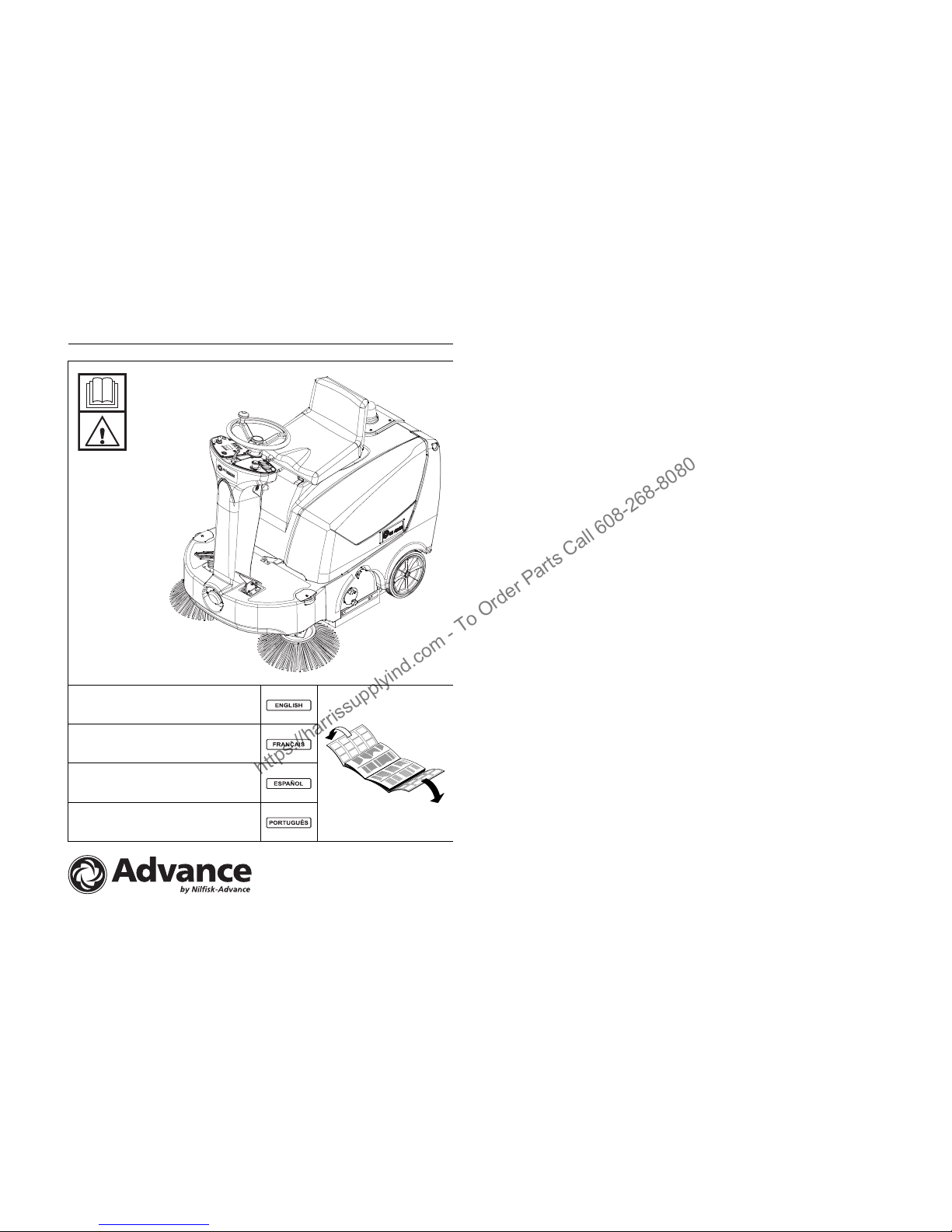
Terra™ 3700B
INSTRUCTIONS FOR USE
Advance model: 908 4203 010
MODE D’EMPLOI ET D’ENTRETIEN
Modèle Advance: 908 4203 010
INSTRUCCIONES DE USO
Modelo Advance: 908 4203 010
INSTRUÇÕES DE USO
Modelo Advance: 908 4203 010
https://harrissupplyind.com - To Order Parts Call 608-268-8080
Page 2
TerraTM 3700B - 146 1963 000(2)2006-06
1
1
2
12
1
14
3
4
5
2
8
6
7
13
11
10
9
15
7b
7a
28
30
2
4
33
3
1
31
9
5
27
25
17
26
19
11
20
21
22
29
35
10
15
11
23
16
24
18
14
12
32
13
34
8
6
36
7
D
S310027
E
S310028
F
S310029
G
S310030
H
S310198
I
S310032
J
S310199
K
S310034
B
S311282
C
S311283
https://harrissupplyind.com - To Order Parts Call 608-268-8080
Page 3

INSTRUCTIONS FOR USE
146 1963 000(2)2006-06 – Terra™ 3700B 1
INTRODUCTION ................................................................................................................................... 2
MANUAL PURPOSE AND CONTENTS ........................................................................................................... 2
TARGET ........................................................................................................................................................... 2
HOW TO KEEP THIS MANUAL ....................................................................................................................... 2
IDENTIFICATION DATA ................................................................................................................................... 2
OTHER REFERENCE MANUALS .................................................................................................................... 2
SPARE PARTS AND MAINTENANCE ............................................................................................................. 2
MODIFICATIONS AND IMPROVEMENTS ....................................................................................................... 2
SAFETY ............................................................................................................................................................ 2
SYMBOLS ......................................................................................................................................................... 3
GENERAL INSTRUCTIONS ............................................................................................................................. 3
UNPACKING ..................................................................................................................................................... 4
MACHINE DESCRIPTION ..................................................................................................................... 4
TERRA™ 3700B OPERATION ......................................................................................................................... 4
CONVENTIONS ................................................................................................................................................ 4
DESCRIPTION ................................................................................................................................................. 4
TECHNICAL DATA ............................................................................................................................... 6
ACCESSORIES/OPTIONS ............................................................................................................................... 7
USE ........................................................................................................................................................ 7
BATTERY CHECK/SETTING ON A NEW MACHINE ...................................................................................... 7
WET OR GEL BATTERY SETTING ................................................................................................................. 8
BEFORE MACHINE START-UP ....................................................................................................................... 8
STARTING AND STOPPING THE MACHINE .................................................................................................. 8
MACHINE OPERATION ................................................................................................................................... 9
HOPPER EMPTYING ....................................................................................................................................... 9
AFTER USING THE MACHINE ...................................................................................................................... 10
PUSHING/TOWING THE MACHINE .............................................................................................................. 10
MACHINE LONG INACTIVITY ....................................................................................................................... 10
FIRST PERIOD OF USE ................................................................................................................................ 10
MAINTENANCE .................................................................................................................................. 10
SCHEDULED MAINTENANCE TABLE .......................................................................................................... 11
MAIN BROOM HEIGHT CHECK AND ADJUSTMENT .................................................................................. 11
MAIN BROOM REPLACEMENT .................................................................................................................... 12
SIDE BROOM HEIGHT CHECK AND ADJUSTMENT ................................................................................... 12
SIDE BROOM REPLACEMENT ..................................................................................................................... 12
FRAME POCKET DUST FILTER CLEANING AND INTEGRITY CHECK ...................................................... 13
SKIRT HEIGHT AND OPERATION CHECK .................................................................................................. 13
HOOD SAFETY SWITCH OPERATION CHECK ........................................................................................... 14
BATTERY CHARGE ....................................................................................................................................... 14
SAFETY FUNCTIONS ......................................................................................................................... 15
EMERGENCY SWITCH .................................................................................................................................. 15
HOOD SAFETY SWITCH ............................................................................................................................... 15
DRIVER'S SEAT MICROSWITCH .................................................................................................................. 15
TROUBLESHOOTING ........................................................................................................................ 15
SCRAPPING ........................................................................................................................................ 16
https://harrissupplyind.com - To Order Parts Call 608-268-8080
Page 4
INSTRUCTIONS FOR USE
2 Terra™ 3700B – 146 1963 000(2)2006-06
INTRODUCTION
MANUAL PURPOSE AND CONTENTS
The purpose of this manual is to provide the customer with
all necessary information to use the machine properly in a
safe and autonomous way.
It contains information about technical characteristics,
operation, machine inactivity, maintenance, spare parts
and safety conditions.
Before carrying out any procedure on the machine, the
operators and qualified technicians must read this manual
carefully. Contact the manufacturer in case of doubts
regarding the interpretation of the instructions and for any
further information.
TARGET
This manual is intended as a guide for the operator and
the technicians qualified to perform the machine
maintenance.
The Operators must not carry out operations reserved for
qualified Technicians. The manufacturer will not be
answerable for damages coming from the
non-observance of this prohibition.
HOW TO KEEP THIS MANUAL
The Instructions for Use must be kept near the machine,
inside an adequate case, away from liquids and other
substances that can cause damage to it.
IDENTIFICATION DATA
The machine model and serial number can be found on a
plate (1, Fig. U) affixed to the machine frame and readable
from inside, by simply raising the machine hood (10, Fig.
C).
The machine production year is shown after the date Code
on the serial plate (A04 means January 2004).
This information is useful when requiring machine
replacement parts. Use the following table to write down
the machine identification data for any further reference.
OTHER REFERENCE MANUALS
– Electronic Battery Charger Operating Manual, which
is to be considered an integral part of this manual.
– Moreover, the following manuals are available:
• Spare Parts List (supplied with the machine).
• Service Manual (at Advance Service Centers).
SPARE PARTS AND MAINTENANCE
All necessary operating, maintenance and repair
procedures must be carried out by qualified personnel or
by Advance Service Centers. Only original spare parts
and accessories must be used.
Call Advance for service or to order spare parts and
accessories, specifying the machine model and serial
number.
MODIFICATIONS AND IMPROVEMENTS
Our company constantly improves its products and
reserves the right to make changes and improvements at
its discretion without being obliged to apply such benefits
to the machines that were previously sold.
Any change and/or addition of accessory must be
approved and performed by the manufacturer.
SAFETY
The following symbols indicate potentially dangerous
situations. Always read this information carefully and take
the necessary precautions to protect people and objects.
The machine operator's cooperation is essential in order
to prevent injury. No accident prevention program is
effective without the total cooperation of the person
responsible for the machine operation. Most of the
accidents that may occur in a factory, while working or
moving around, are caused by failure to comply with the
simplest rules for exercising prudence. A careful and
prudent operator is the best guarantee against accidents
and is essential for successful completion of any
prevention program.
MACHINE model .........................................................
MACHINE serial number .............................................
https://harrissupplyind.com - To Order Parts Call 608-268-8080
Page 5

INSTRUCTIONS FOR USE
146 1963 000(2)2006-06 – Terra™ 3700B 3
SYMBOLS
GENERAL INSTRUCTIONS
Specific warnings and cautions to inform about potential
damages to people and machine are shown below.
– Remove the key from the ignition switch and
disconnect the batteries before performing any
maintenance/repair procedure.
– This machine must be used by properly trained and
authorized personnel only. Children or disabled
people cannot use this machine.
– Keep sparks, flames and smoke away from the
batteries. During the normal operation explosive
gases are released.
– Do not wear jewelry when working near electrical
components.
– Do not work under the lifted machine, if it is not
securely fixed.
– Do not operate the machine near toxic, dangerous,
inflammable and/or explosive powders, liquids or
vapors.
– Battery charging produces highly explosive hydrogen
gas. Keep the hood open during battery charging and
perform this operation in well-ventilated areas and
away from naked flames.
– Carefully read all the instructions before carrying out
any maintenance/repair operations.
– Take all necessary precautions to prevent hair,
jewelry and loose clothes from being caught by the
machine moving parts.
– Do not smoke while charging the batteries.
– Before connecting the battery charger to the mains,
be sure that frequency and voltage indicated in the
related Manual correspond to the mains voltage.
– Do not charge the batteries if the battery charger
cable or the plug are damaged. If the machine is not
working as it should, has been damaged, left
outdoors or dropped into water, return it to the
Service Center.
– Do not pull or carry the machine by the battery
charger cable and never use the battery charger
cable as a handle. Do not close a door on the supply
cable, or pull the supply cable around sharp edges or
corners. Do not run the machine on the battery
charger cable.
– Keep the battery charger cable away from heated
surfaces.
– To reduce the risk of fire, electric shock, or injury, do
not leave the machine unattended when it is plugged
in.
– To avoid electric shock, do not expose to rain. Store
the machine indoors.
– Do not allow to be used as a toy. Close attention is
necessary when used near children.
– Use only as described in this Manual. Use only
Manufacturer's recommended accessories.
– Do not leave the machine unattended with the ignition
key inserted and the parking brake disengaged.
– Do not use the machine on slopes with a gradient
exceeding the value shown on the machine serial
number plate.
– Do not wash the machine with pressurized water, or
with corrosive substances. Do not use compressed
air to clean this type of machine.
– Do not use the machine in particularly dusty areas.
– While using this machine, take care not to cause
damage to other people, especially children.
– The storage temperature must be between 32°F and
104°F (0°C and +40°C).
– The machine operating temperature must be
between 32°F and 104°F (0°C and +40°C).
– The humidity must be between 30% and 95%.
– Always protect the machine against the sun, rain and
bad weather, both under operation and inactivity
condition.
– Do not use the machine as a means of transport.
– Do not allow the brooms to operate while the machine
is stationary to avoid damaging the floor.
– In case of fire, possibly use a powder fire
extinguisher, not a water one.
– Do not bump into shelves or scaffoldings, particularly
where there is a risk of falling objects.
– Adjust the operation speed to suit the floor conditions.
DANGER!
It indicates a dangerous situation (risk of
death) for the operator.
WARNING!
It indicates a potential risk of injury for
people.
CAUTION!
It indicates a caution or a remark related to
important or useful functions. Pay particular
attention to the paragraphs marked by this
symbol.
CONSULTATION
Consult the Instructions for Use before
performing any operation.
14
DANGER!
WARNING!
https://harrissupplyind.com - To Order Parts Call 608-268-8080
Page 6

INSTRUCTIONS FOR USE
4 Terra™ 3700B – 146 1963 000(2)2006-06
– Do not tamper with the machine safety guards and
follow the routine maintenance instructions
scrupulously.
– Do not remove or modify the plates affixed to the
machine.
– In case of machine malfunctions, ensure that these
are not due to lack of maintenance. Otherwise,
request assistance from the authorized personnel or
from an authorized Service Center.
– In case of part replacement, order ORIGINAL spare
parts from an authorized dealer or retailer.
– To ensure the proper and safe operation of the
machine, have the scheduled maintenance, detailed
in the related chapter of this manual, performed by
the authorized personnel or an authorized Service
Center.
– The machine must be disposed of properly, because
of the presence of toxic-harmful materials (batteries,
oils, etc.), which are subject to standards that require
disposal in special centers (see the Scrapping
chapter).
– If the machine is used according to the instructions,
the vibrations do not cause dangerous situations.
The machine vibration level is less than 98.42 in/s
2
(2.5 m/s2) (98/37/EEG-EN-1033/1995-EN 1032).
– When lead (WET) batteries are installed on the
machine, do not tilt the machine of more than 30
degree from the horizontal plane to prevent the highly
corrosive acid from leaking out of the batteries. When
the machine is to be tilted for maintenance
operations, remove the batteries.
UNPACKING
Upon delivery carefully check that the machine and its
packing, if any, have not been damaged during
transportation. In case of visible damages, keep the
packing and have it checked by the Parcel Service that
delivered it. Call the Parcel Service immediately to fill in a
request for damage compensation.
Please check that the following items have been supplied
with the machine:
Technical documents:
– Instructions for Use of Terra™ 3700B
– Electronic Battery Charger Operating Manual
– Spare Parts List of Terra™ 3700B
MACHINE DESCRIPTION
TERRA™ 3700B OPERATION
The Terra™ 3700B sweeper has been designed and built
to be used by a qualified operator to clean (by sweeping
and vacuuming) smooth and solid floors in civil and
industrial environments and to collect dust and light debris
under safe operation conditions.
CONVENTIONS
Forward, backward, front, rear, left or right are intended
with reference to the operator’s position, that is to say
on the driver’s seat with the hands on the steering wheel
(1, Fig. C).
DESCRIPTION
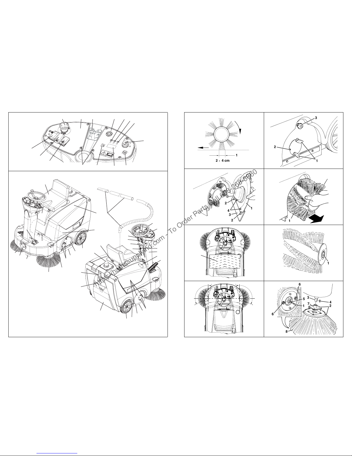
Control panel
(See Fig. B)
1. Left control panel
2. Ignition switch
3. Discharged battery warning light
4. Semi-discharged battery warning light
5. Charged battery warning light
6. Display
7. Display selection push-button: hour counter/hour and
minute counter/battery voltage (V)
8. Horn
9. Switch having the following functions:
– central position: OFF
– pushed forward (fixed): activates the main broom
rotation and the vacuum fan
– pushed backward (not fixed): activates the filter
shaker
10. Manual vacuum switch (optional)
11. Working light switch (optional)
12. Emergency push-button
13. Control panel fixing screws
14. Right control panel
15. Steering column inclination adjusting lever
https://harrissupplyind.com - To Order Parts Call 608-268-8080
Page 7

INSTRUCTIONS FOR USE
146 1963 000(2)2006-06 – Terra™ 3700B 5
Outside view
(See Fig. C)
1. Steering wheel
2. Control panel
3. Vacuum activation/deactivation lever
4. Side broom lifting/lowering lever
5. Forward/reverse gear pedal
6. Service brake pedal
7. Parking brake lever (it acts on the front wheel)
7a. Lever in the position of brake engaged
7b. Lever in the position of brake disengaged
8. Front skirt lifting pedal
9. Can holder
10. Hood
11. Rear wheels on fixed axle
12. Front drive and steering wheel
13. Right side broom
14. Left side broom
15. Main broom
16. Left side skirt
17. Right side skirt
18. Front skirt
19. Rear skirt
20. Hopper
21. Hopper hook
22. Hopper handle
23. Removable door for main broom extraction
24. Main broom height left adjuster
25. Main broom height right adjuster
26. Main broom right door
27. Main broom right door fixing screws
28. Pivoting light (always on when the ignition switch is
turned to “I” position) (optional)
29. Driver's seat with safety microswitch
30. Additional hole for manual vacuum kit (optional)
31. Adjustable steering column
32. Working light (optional)
33. Side broom height adjusting knob
34. Seat longitudinal position adjusting lever
35. Manual vacuum kit (optional)
36. Side broom height adjusting knob ring nut
Under-hood compartment
(See Fig. U)
1. Serial number plate/technical data
2. Hood (open)
3. Hood support rod
4. Batteries
5. Battery caps (for lead batteries)
6. Battery connector
7. Electronic battery charger
8. Battery charger electrical cable
9. Lamellar fuse box (services)
10. Main broom/fan motor circuit breaker
11. Drive circuit breaker
12. Lead (WET) or gel (GEL) battery selector switch
located on the electronic battery charger
13. Charged battery warning light
14. Main broom belt
15. Main broom drive pulley
16. Vacuum fan
17. Main motor
18. Manual vacuum system (optional)
19. Switch for push operated machine
20. Battery connection diagrams
https://harrissupplyind.com - To Order Parts Call 608-268-8080
Page 8

INSTRUCTIONS FOR USE
6 Terra™ 3700B – 146 1963 000(2)2006-06
TECHNICAL DATA
Wiring diagram
(See Fig. V)
Legend
BAT: Batteries
BE1: Pivoting light
BZ1: Reverse gear warning buzzer
C1: Battery connector
CH1: Battery charger
EB1: Hour counter and battery voltage display
EB2: Drive electronic board
ES0: Starting relay
ES1: Main broom switch
ES2: Filter shaker relay
ES3: Manual vacuum switch
FA: Main broom/fan fuse
FL: Drive electronic board safety fuse (3A)
FT: Drive fuse
F1: Main fuse (ignition switch circuit) (25A)
F2: Filter shaker motor fuse (25A)
F3: Manual vacuum fuse (40A) (optional)
F4: Horn and pivoting light fuse (10A) (optional)
F5: Working light fuse (10A) (optional)
F6: Side broom motor fuse (10A)
HN1: Horn
K1: Ignition switch
L1: Working light (optional)
M1: Main broom motor
M2: Drive motor
M3: Filter shaker motor
M4: Right side broom motor
M5: Left side broom motor
M6: Manual vacuum motor (optional)
P1: Horn push-button
R1: Drive speed potentiometer
SWC: Hood safety switch
SWS: Emergency push-button
SW1: Main broom, vacuum fan and filter shaker switch
SW2: Driver's seat safety microswitch
SW3: Forward/reverse gear microswitch
SW4: Side broom microswitch
SW5: Drive switch
SW6: Manual vacuum switch (optional)
SW7: Working light switch
General Values
Machine length 49.40 in (1,255 mm)
Machine width (w/o side brooms) 31.30 in (795 mm)
Machine height 45.47 in (1,155 mm)
Working width w/ side brooms 39.37 in (1,000 mm)
Working width w/o side brooms 23.62 in (600 mm)
Minimum ground clearance
(skirts not included)
1.57 in (40 mm)
Minimum turning radius 38.70 in (983 mm)
Main broom dimensions
Ø 10.43 in x 23.62 in
(Ø 265 mm x 600 mm)
Side broom dimensions Ø 16.53 in (Ø 420 mm)
Front drive and steering wheel
Ø 7.87 in x 1.97 in
(Ø 200 x 50 mm)
Rear wheels
Ø 9.84 in x 1.97 in
(Ø 250 x 50 mm)
Machine weight w/o batteries 65.27 lb (143.89 kg)
Maximum forward/backward speed
8.85 mph / 7.08 mph
(5.5 Km/h / 4.4 Km/h)
Maximum slope 16%
Hopper capacity 1.41 ft
3
(40 liters)
Main broom and fan motor 600 W
Side broom motors 60 W
Drive motor 400 W
Filter shaker motor 12 W
Sound pressure level (A Lpa) 71.6 dB(A)
Batteries Values
Battery voltage 24 V
Standard battery
Lead (WET), with acid
electrolyte
Optional battery Gel (GEL), hermetic
Usable battery capacity 100 – 240 Ah C5
Battery compartment max. size
14.05x14.76x15.16 in
(357x375x385 mm)
Dust vacuuming and filtering Values
Paper dust filter 5-10 µm 32.3 ft
2
(3m2)
Vacuum in main broom compartment
0.72 in H
2
O
(18.3 mm H2O)
https://harrissupplyind.com - To Order Parts Call 608-268-8080
Page 9
INSTRUCTIONS FOR USE
146 1963 000(2)2006-06 – Terra™ 3700B 7
Color code
BK: Black
BU: Blue
BN: Brown
GN: Green
GY: Grey
OG: Orange
PK: Pink
RD: Red
VT: Violet
WH: White
YE: Yellow
Electrical fuses
The following fuses, which can be reset by pressing the
related key, are located under the hood (10, Fig. C):
– Drive fuse (11, Fig. U)
– Main broom/fan motor fuse (10, Fig. U)
– Lamellar fuses, protected by a transparent plastic
cover (9, Fig. U), which protect the following circuits:
– F1 (25A): Main fuse (ignition switch circuit)
– F2 (25A): Filter shaker motor
– F3 (40A): Manual vacuum (optional)
– F4 (10A): Horn and pivoting light
– F5 (10A): Working light (optional)
– F6 (10A): Side broom motors
– F7 (25A): Spare fuse
– F8 (10A): Spare fuse
On the drive system electronic board there is the following
fuse:
– Drive system electronic board fuse (3 A)
ACCESSORIES/OPTIONS
In addition to the standard components, the machine can
be equipped with the following accessories/options,
according to the machine specific use:
– Gel batteries;
– Main and side brooms with harder or softer bristles;
– Antistatic polyester or polyester BIA C dust filter;
– Manual vacuum;
– Working light;
– Pivoting light;
– Skirts of various material.
For further information concerning the optional
accessories, apply to an authorized retailer.
USE
While reading this manual, the operator must pay
particular attention to these symbols.
Do not cover these plates for any reason and immediately
replace them if they are damaged.
BATTERY CHECK/SETTING ON A NEW
MACHINE
The machine requires two 12V batteries or four 6V
batteries connected according to the diagram (20, Fig. U).
The machine can be set in one of the following modes:
a) Lead or gel batteries installed on the machine and
ready to be used
1. Raise the machine hood (10, Fig. C) and engage
the hood support rod (3, Fig. U), then check that
the batteries are connected to the machine
through the special connector (6, Fig. U).
2. Disengage the hood support rod and lower the
hood. Check the hood is properly closed (the
machine must be as shown in Fig. C).
3. Insert the key into the ignition switch (2, Fig. B) on
the control panel and turn it to “I” position (without
pressing the pedal 5, Fig. C), then release it. If the
green warning light (5, Fig. B) turns on, the battery
is ready to be used. If the yellow (4, Fig. B) or red
(3, Fig. B) warning light turns on, it is necessary to
charge the batteries (see the relevant procedure
in the Maintenance chapter).
WARNING!
On some points of the machine there are
some adhesive plates indicating:
– DANGER
– WARNING
– CAUTION
–CONSULTATION
https://harrissupplyind.com - To Order Parts Call 608-268-8080
Page 10
INSTRUCTIONS FOR USE
8 Terra™ 3700B – 146 1963 000(2)2006-06
b) Lead batteries installed on the machine but dry,
that is without electrolyte
1. Raise the machine hood (10, Fig. C) and engage
the hood support rod (3, Fig. U).
2. Remove all the battery caps (5, Fig. U).
3. Fill the cells (or each element) of the batteries with
sulfuric acid for batteries (density from 0.57 to
0.58 lb at 77°F (from 1.27 to 1.29 Kg at 25°C)) in
accordance with the instructions given in the
Battery User's Manual. The correct quantity of
sulfuric acid to fill in is given in the Battery User's
Manual.
4. Let the batteries rest and fill the cells up with
sulfuric acid in accordance with the instructions
given in the Battery User's Manual.
5. Charge the batteries (see the relevant procedure
in the Maintenance chapter).
c) Without battery
1. Buy appropriate batteries (See the Technical Data
paragraph and the diagram 20, Fig. U). For the
battery choice and installation, apply to qualified
battery retailers.
2. Install the batteries.
3. Set the machine and the battery charger
according to the type of batteries installed.
Proceed as follows.
WET OR GEL BATTERY SETTING
It is necessary to set the electronic board of the machine
and of the battery charger according to the type of battery
installed (lead or gel). Proceed as follows:
1. Turn the ignition switch (2, Fig. B) to “0” position.
2. Raise the hood (10, Fig. C) and engage the hood
support rod (3, Fig. U).
Machine setting
The machine factory setting is for lead (WET) batteries. If
this setting corresponds to the type of battery installed on
your machine, go to the next paragraph, otherwise
perform the following operations:
– Disconnect the battery connector (6, Fig. U).
– Unscrew the control panel fixing screws (13) and
carefully remove the right control panel (14, Fig. B).
– Install a jumper wire (1, Fig. T) on the GEL
connectors (3) for gel batteries.
– Carefully reassemble the control panel (14, Fig. B)
and fix it by using the related fixing screws.
– Reconnect the battery connector (6, Fig. U).
Battery charger setting
1. Position the selector switch (12, Fig. U) to WET for
lead batteries or to GEL for gel batteries.
2. Charge the batteries (see the relevant procedure in
the Maintenance chapter).
BEFORE MACHINE START-UP
STARTING AND STOPPING THE MACHINE
Starting the machine
1. Sit on the driver's seat (29, Fig. C) and, if it is
necessary for an easier access to the machine, push
the lever (15, Fig. B) and tilt the steering column (31,
Fig. C) forward.
2. Push the lever (15, Fig. B) forward and tilt the steering
column (31, Fig. C) forward or backward, to reach a
comfortable position. Then release the lever (16, Fig.
B) and lock the steering column.
3. Without pressing the forward/reverse gear pedal (5,
Fig. C), turn the ignition switch (2, Fig. B) to “II”
position, then release it; it will go back to “I” position.
Check that the green warning light (5, Fig. B) (battery
charged) turns on. If the yellow or red warning light (3
or 4, Fig. B) turns on, turn the ignition switch back to
“0” position, then charge the batteries (see the
relevant procedure in the Maintenance chapter).
WARNING!
Be extremely careful when working with
sulfuric acid, as it is corrosive. If it comes in
contact with skin or eyes, rinse thoroughly
with water and call a physician.
Batteries have to be filled in a well-ventilated
area.
Wear protective gloves.
CAUTION!
Make sure that there are no open
doors/hoods and that the machine is in
normal operating conditions.
Make sure that the hopper (20, Fig. C) is
properly closed.
If the machine has not been used after being
transported, check that all the blocks used
for the transportation have been removed.
https://harrissupplyind.com - To Order Parts Call 608-268-8080
Page 11

INSTRUCTIONS FOR USE
146 1963 000(2)2006-06 – Terra™ 3700B 9
4. Disengage the parking brake according to the
following procedure:
– Press the pedal (6, Fig. C) and turn the lever (7)
from (7a) position to (7b) position.
– Release the pedal (6).
5. Drive the machine to the working area, by keeping
your hands on the steering wheel and pressing the
pedal (5, Fig. C) on the front side to move forward and
on the rear side to move backward. The drive speed
can be adjusted from zero to maximum speed by
increasing the pressure exerted on the pedal (5, Fig.
C).
6. Activate the main broom and the vacuum fan by
pushing the switch (9, Fig. B) forward.
7. Activate the vacuum system by using the lever
(3, Fig. C).
8. Lower the side brooms (13 and 14, Fig. C) by
lowering the lever (4).
9. Start the sweeping work, by turning the steering
wheel (1, Fig. C) and moving the machine forward
through the pedal (5).
Stopping the machine
1. To stop the machine, release the pedal (5, Fig. C). To
stop the machine more quickly, also press the service
brake pedal (6, Fig. C). In case of emergency, press
the emergency push-button (12, Fig. B) to
immediately stop the machine. To deactivate the
emergency push-button (12) after pressing it, rotate it
clockwise.
2. Lift the side brooms (13 and 14, Fig. C) by using the
lever (4).
3. To stop the main broom and the vacuum fan, turn the
switch (9, Fig. B) to “0” (central) position.
4. To stop the machine, turn the ignition switch (2, Fig.
B) to “0” position.
5. Engage the parking brake according to the following
procedure:
– Press the pedal (6, Fig. C) as necessary, then
engage the brake by turning the lever (7) from (7b)
position to (7a) position.
– Release the pedal (6).
MACHINE OPERATION
1. Avoid stopping for a long time with the machine in the
same position and the brooms rotating: this could
create unwanted marks on the floor.
2. To collect light and bulky debris, lift the front skirt by
pressing the pedal (8, Fig. C); remember that while
the front skirt is lifted, the machine suction power
decreases.
3. For the machine proper operation, the dust filter must
be as clean as possible. To keep the dust filter clean
while sweeping, deactivate the vacuum system by
operating the lever (3, Fig. C), then press the filter
shaker (9, Fig. B) push-button for a short while.
During this operation the main motor and the vacuum
fan automatically shut off.
After cleaning the filter, push the switch (9, Fig. B)
forward by reactivating the main broom and the
vacuum system, then start sweeping again.
While working, repeat the operation every 10 minutes
on average (depending on the dustiness of the area
to be cleaned).
4. The hopper (20, Fig. C) should be dumped after each
working period and whenever it is full (see the
relevant procedure in the next paragraph).
HOPPER EMPTYING
1. Stop the machine by releasing the forward/reverse
gear pedal.
2. Turn the ignition switch (2, Fig. B) to “0” position.
3. Disengage the hook (21, Fig. C) by pulling its lower
end.
4. Remove the hopper (20) by using the handle (22, Fig.
C) and dump it in special containers.
5. Reinsert the hopper and fix it by using the hook (21).
6. The machine is ready to start working again.
NOTE
The seat (29, Fig. C) is equipped with a
safety sensor, which allows the machine to
be moved through the pedal (5, Fig. C) only
when the operator is seated in the driver's
seat.
NOTE
The side brooms (13 and 14, Fig. C) can be
lowered and lifted even when the machine is
moving. The side brooms do not rotate when
they are lifted, but they rotate when they are
lowered.
WARNING!
When operating on wet grounds, it is
essential to deactivate the vacuum system
by operating the lever (3, Fig. C) to prevent
the dust filter from being damaged.
NOTE
When the dust filter is obstructed and/or the
hopper is full, the machine cannot collect
dust and debris.
https://harrissupplyind.com - To Order Parts Call 608-268-8080
Page 12

INSTRUCTIONS FOR USE
10 Terra™ 3700B – 146 1963 000(2)2006-06
AFTER USING THE MACHINE
After working, before leaving the machine:
– Lift the side brooms by using the lever (4, Fig. C).
– Activate the filter shaker by using the switch (9, Fig.
B).
– Dump the hopper (20, Fig. C) (see the previous
paragraph).
– Remove the key from the ignition switch (2, Fig. B).
– Engage the parking brake according to the following
procedure:
– Press the pedal (6, Fig. C) as necessary, then
engage the brake by turning the lever (7) from (7b)
position to (7a) position.
– Release the pedal (6).
PUSHING/TOWING THE MACHINE
To easily push/tow the machine when it is off, proceed as
follows:
– Raise the hood (10, Fig. C).
– Turn the switch (19, Fig. U) to “0” and close the hood
(10, Fig. C).
– Push or tow the machine.
– After pushing/towing the machine, turn the switch
(19, Fig. U) back to “I”.
MACHINE LONG INACTIVITY
If you foresee that the machine will not be used for more
than 30 days, proceed as follows:
1. Check that the machine storage area is dry and
clean.
2. Disconnect the battery connector (6, Fig. U).
3. Slightly lift the machine so that the skirts, the main
broom and the wheels do not touch the ground.
4. Disconnect the positive battery charger (7, Fig. U)
terminal (+) directly from the battery (+) pole.
FIRST PERIOD OF USE
After the first period of use (first 8 hours) it is necessary to
carry out the following operations:
1. Check the fixing and connecting parts of the machine
for proper tightening.
2. Check the visible parts for integrity and leakage.
MAINTENANCE
The lifespan of the machine and maximum operating
safety are ensured by correct and regular maintenance.
The following chart provides the scheduled maintenance.
The intervals shown may vary according to particular
working conditions, which are to be defined by the person
in charge of the maintenance.
All scheduled or extraordinary maintenance operations
must be performed by qualified personnel, or by an
authorized Service Center.
This manual describes only the easiest and most common
maintenance procedures.
WARNING!
To carry out maintenance operations, switch
off the machine (remove the key from the
ignition switch) and, if necessary,
disconnect the battery.
Moreover, carefully read the instructions in
the Safety chapter.
NOTE
For other maintenance procedures
contained in the scheduled maintenance
chart, refer to the Service Manual that can be
consulted at any Service Center.
https://harrissupplyind.com - To Order Parts Call 608-268-8080
Page 13

INSTRUCTIONS FOR USE
146 1963 000(2)2006-06 – Terra™ 3700B 11
SCHEDULED MAINTENANCE TABLE
(*): for the related procedure, see the Service Manual.
(1): and after the first 8 running-in hours.
MAIN BROOM HEIGHT CHECK AND
ADJUSTMENT
1. Check that the main broom is at the correct height
from the ground, proceeding as follows:
– Drive the machine on a level ground.
– Keep the machine stationary and rotate the main
broom for a few seconds.
– Stop and lift the main broom, then move the
machine.
– Check that the main broom print (1, Fig. D), along
its length, is from 0.79 to 1.57 in (20 to 40 mm)
wide.
If the print (1) is not within specifications, it is
necessary to adjust the broom height, proceeding
as described in step 2.
2. Drive the machine on a level ground and engage the
parking brake (6 and 7, Fig. C).
3. Turn the ignition switch (2, Fig. B) to “0” position.
4. Loosen the knobs (1, Fig. E) on both sides of the
machine.
5. Operating on the knobs (1, Fig. E) move, on both
sides of the machine, the broom height variation
indicator (2) as necessary and then screw down the
knobs (1).
The indicator (2) must be in the same position on both
sides of the machine; the maximum difference
allowed to obtain the print (1, Fig. D) described in step
1 (0.79 to 1.57 in (20 to 40 mm) wide)) is 2 notches.
6. Perform step 1 again to check that the main broom is
at the correct height from the ground.
7. When the broom is too worn and can no longer be
adjusted, replace it according to the instructions in the
following paragraph.
Maintenance operation On delivery
Every 10
hours
Every 50
hours
Every 100
hours
Every 200
hours
Every 400
hours
Battery fluid level check zz
Side and main broom height check and
adjustment
zz
Dust filter cleaning and integrity check z
Skirt height and operation check zz
Filter shaker operation check z (*)
Hood safety switch operation check z (*)
Main broom drive belt visual inspection zz (*)
Nut and screw tightening check z (*) (1)
Service and parking brake check and
adjustment
z (*)
Main broom drive belt replacement z (*)
Main motor and drive motor carbon brush
check and replacement
z (*)
NOTE
Brooms of various hardness are available.
This procedure is applicable to all types of
brooms.
CAUTION!
An excessive print (larger than 4 cm) of the
main broom can lead to the machine
malfunction and the overheating of the
moving parts, thus reducing machine life.
Be extremely careful when performing the
above-mentioned checks and always use
the machine according to the indicated
conditions.
https://harrissupplyind.com - To Order Parts Call 608-268-8080
Page 14
INSTRUCTIONS FOR USE
12 Terra™ 3700B – 146 1963 000(2)2006-06
MAIN BROOM REPLACEMENT
1. Drive the machine on a level ground and engage the
parking brake (6 and 7, Fig. C).
2. Turn the ignition switch (2, Fig. B) to “0” position.
3. Loosen the knobs (1, Fig. E) on both sides of the
machine.
4. Move the broom height variation indicators (2, Fig. E)
until the broom is at the maximum ground clearance.
Screw down the knobs (1).
5. On the left side of the machine, loosen the knob (3,
Fig. E).
6. Remove the broom door (1, Fig. F) by pulling it
upwards to disengage the retainers (2).
7. Remove the broom (1, Fig. G).
8. The new broom must be installed with the bristles
rows bent as shown in the figure H (top view).
9. Install the new broom on the machine and ensure that
its mesh (1, Fig. I) correctly fits into the related drive
hub (4, Fig. R). Check that the drive hub is free from
dirt or foreign materials (cords, rags, etc.)
accidentally rolled up.
10. Reinstall the broom door (1, Fig. F), engaging the
retainers (2).
11. Screw down the knob (3, Fig. E).
12. Carry out the main broom height check and
adjustment, as described in the previous paragraph.
SIDE BROOM HEIGHT CHECK AND
ADJUSTMENT
1. Check the side broom height from the ground,
proceeding as follows:
– Drive the machine on a level ground and lower the
side brooms.
– Keep the machine stationary, lower the side
brooms and rotate them for a few seconds.
– Stop and lift the side brooms, then move the
machine and switch it off.
– Check if the size and orientation of the prints left
by the side brooms are as shown in the figure (1
and 2, Fig. J).
In case the prints are not within specifications, it is
necessary to adjust the broom height, proceeding as
described in the following step.
2. Unlock the ring nut (36, Fig, C) by turning it
counterclockwise, then turn the knob (33) as
necessary, clockwise or counterclockwise, to adjust
the broom height; then lock the knob (33) with the ring
nut (36).
3. Perform step 1 again to check the proper adjustment
of the side broom height from the ground.
4. When the brooms are too worn to be adjusted,
replace them as shown in the next paragraph.
SIDE BROOM REPLACEMENT
1. Drive the machine on a level ground and engage the
parking brake (6 and 7, Fig. C).
2. Turn the ignition switch (2, Fig. B) to “0” position.
3. Remove the screw (1, Fig. K) inside the side broom,
then remove the broom and the hub (2) by
disengaging it from the shaft (3).Recover the key (4)
and the washer (5).
4. At the workbench, remove the two screws and nuts
(6) and separate the broom (8) from the hub (7).
5. Install the new broom (8) on the hub (7) and tighten
the screws and the nuts (6).
6. Reinstall the new broom and the hub (2) on the
machine after seating the key (4). Reinstall the
washer (5) and tighten the screw (1).
7. Carry out the side broom height check and
adjustment as described in the previous paragraph.
NOTE
Brooms of various hardness are available.
This procedure is applicable to all types of
brooms.
CAUTION!
It is advisable to use protective gloves when
replacing the main broom because there can
be cutting debris between the bristles.
NOTE
Brooms of various hardness are available.
This procedure is applicable to all types of
brooms.
NOTE
Brooms of various hardness are available.
This procedure is applicable to all types of
brooms.
CAUTION!
It is advisable to use protective gloves when
replacing the side brooms because there
can be cutting debris between the bristles.
https://harrissupplyind.com - To Order Parts Call 608-268-8080
Page 15

INSTRUCTIONS FOR USE
146 1963 000(2)2006-06 – Terra™ 3700B 13
FRAME POCKET DUST FILTER CLEANING
AND INTEGRITY CHECK
1. Drive the machine on a level ground and engage the
parking brake (6 and 7, Fig. C).
2. Turn the ignition switch (2, Fig. B) to “0” position.
3. Remove the hopper hook (21, Fig. C).
4. Remove the hopper (20) by using the handle (22, Fig.
C).
5. Turn the handle (1, Fig. L) downwards (90 degree
approximately) and let the filter frame (2) rotate
outwards.
6. Pull out the dust filter (3) upwards.
7. In an appropriate outdoor area, clean the filter
shaking it on a level and clean surface, tapping the
side (1, Fig. M) opposite the wire gauze (2). Complete
the cleaning by using compressed air (3) at max. 6
bars, blowing only from the side protected by the wire
gauze (2), at a minimum distance of 30 cm.
According to the filter type, observe the following
cautions:
– Paper filter (standard): Do not use water or
detergents to clean it not to irreparably damage
the filter.
– Polyester filter (optional): To clean it, see the
above-mentioned instructions. If necessary, for a
better cleaning, it is allowed to wash the filter with
water and non-lathering detergents. This provides
better quality cleaning but reduces the life of the
filter, which will have to be replaced more
frequently. The use of inadequate detergents can
damage the filter.
8. Check the filter body for tears.
9. If necessary, clean the filter compartment rubber seal
(4, Fig. L) along its perimeter and check it for integrity.
If necessary, replace it.
10. Reassemble in the reverse order of disassembly.
SKIRT HEIGHT AND OPERATION CHECK
1. Drive the machine on a level ground that is suitable
for checking the skirt height. Engage the parking
brake (6 and 7, Fig. C).
2. Turn the ignition switch (2, Fig. B) to “0” position.
Side skirt check
1. Check the side skirts (16 and 17, Fig. C) for integrity.
Replace the skirts when they have cuts (1, Fig. N)
larger than 0.79 in (20 mm) or cracks (2) larger than
0.39 in (10 mm) (for skirt replacement, refer to the
Service Manual).
2. Check that the side skirt (16 and 17, Fig. C) height
from the ground is within 0 and 0.12 in (0 and 3 mm)
(Fig. O). If necessary, adjust the skirt height,
proceeding as follows:
Left skirt:
– Raise the machine hood (10, Fig. C) and engage
the hood support rod (3, Fig. U).
– Loosen the knob (3, Fig. E) and remove the broom
left door (1, Fig. F), pulling it upwards to
disengage the retainers (2).
– Adjust the skirt (3, Fig. F) height by using its slots
(4).
– Reassemble in the reverse order of disassembly.
Right skirt:
– Remove the main broom, as described in the
related paragraph.
– Remove the belt (14, Fig. U) from the pulley (15);
to facilitate the operation, make the pulley (15)
rotate operating on the fan (16).
– Remove the screws (27, Fig. C) and the right door
(26) together with the belt (14, Fig. U). On the
machine, adjust the skirt (1, Fig. S) height by
using its slots (2).
– Reassemble in the reverse order of disassembly.
NOTE
Besides the standard paper filter, polyester
filters are also available. The following
procedure is applicable to each type of filter.
NOTE
Reassemble the filter with the wire gauze (2,
Fig. M) facing the fan (16, Fig. U).
https://harrissupplyind.com - To Order Parts Call 608-268-8080
Page 16

INSTRUCTIONS FOR USE
14 Terra™ 3700B – 146 1963 000(2)2006-06
Front and rear skirt check
1. Remove the main broom, as described in the related
paragraph.
2. Check the front (1, Fig. R) and rear (2) skirts for
integrity.
3. Replace the skirts when they have cuts (1, Fig. N)
larger than 0.79 in (20 mm) or cracks (2) larger than
0.39 in (10 mm) (for skirt replacement, refer to the
Service Manual).
4. Check that:
– The front skirt (1, Fig. R) slightly touches the
ground or that it is not detached from ground (1,
Fig. P).
– The rear skirt (2, Fig. R) height from ground is
within 0 and 0.12 in (0 and 3 mm) (1, Fig. O).
5. If necessary, adjust the skirt height by using the slots
(3, Fig. R).
6. Press the front skirt lifting pedal (8, Fig. C) and check
that the front skirt (1, Fig. Q) rotates upward of about
90° (as shown in figure); release the pedal and check
that the skirt does not remain in an intermediate
position but returns to its initial position. If necessary,
for the front skirt control cable adjustment or
replacement, refer to the Service Manual.
Reassemble in the reverse order of disassembly.
HOOD SAFETY SWITCH OPERATION
CHECK
Operate the vacuum fan, slightly raise the hood (10, Fig.
C) and check that the fan immediately shuts off.
If raising the hood (10) does not cause the vacuum fan to
shut off, contact an authorized Service Center or retailer.
BATTERY CHARGE
1. Drive the machine on a level ground and engage the
parking brake (6 and 7, Fig. C).
2. Turn the ignition switch (2, Fig. B) to “0” position.
3. Raise the machine hood (10, Fig. C) and engage the
hood support rod (3, Fig. U).
4. For lead battery only: Check the level of electrolyte
inside the batteries; if necessary, top up through the
caps (5, Fig. U).
Leave the caps (5) open for the next battery charge.
If necessary, clean the upper surface of the batteries.
5. Proceed with charging the batteries according to one
of the following methods.
WARNING!
Battery charging produces highly explosive
hydrogen gas. Charge the batteries in
well-ventilated areas and away from naked
flames. Do not smoke while charging the
batteries. While charging the battery always
keep the hood open.
WARNING!
Be extremely careful when charging the
batteries as there may be battery fluid
leakages. The battery fluid is corrosive. If it
comes in contact with skin or eyes, rinse
thoroughly with water and consult a
physician.
https://harrissupplyind.com - To Order Parts Call 608-268-8080
Page 17

INSTRUCTIONS FOR USE
146 1963 000(2)2006-06 – Terra™ 3700B 15
Battery charging with the battery charger installed
on the machine
1. For lead battery only: Check the level of electrolyte
inside the batteries; if necessary, top up through the
caps (5, Fig. U). Leave the caps (5) open for the next
battery charge. When the correct level is reached,
clean, if necessary, the upper surface of the battery.
2. Connect the battery charger electrical cable (8, Fig.
U) to the electrical mains.
3. When the green warning light (13, Fig. U) turns on,
the batteries are charged.
4. For further information about the battery charger
operation (7, Fig. U), see the Battery Charger
Operating Manual.
5. Disconnect the battery charger connector (8, Fig. U)
from the electrical mains and place it in its special
housing.
6. (For lead battery only) Close all the caps (5, Fig. U).
7. Disengage the hood support rod (3, Fig. U) and close
the hood (2); the machine is ready to be used.
SAFETY FUNCTIONS
The machine is equipped with the following safety
functions.
EMERGENCY SWITCH
It is located in an easily accessible position (see 12, Fig.
B); it has to be pressed in case of emergency, to stop all
the machine functions.
To reset it, turn it clockwise.
HOOD SAFETY SWITCH
It is activated when the machine hood is lifted. It stops all
functions.
If the machine keeps operating when the hood is open,
contact an authorized Service Center or retailer.
DRIVER'S SEAT MICROSWITCH
It is located inside the driver's seat and it does not allow
the machine drive system to operate if the operator is not
seated in the driver's seat.
TROUBLESHOOTING
For further information consult the Service Manual,
available at any Advance Service Center.
WARNING!
Check that the voltage and frequency shown
on the machine serial number plate (1, Fig.
U) correspond to the electrical mains values.
NOTE
When the battery charger is connected to
the electrical mains, all machine functions
are automatically cut off.
Trouble Remedy
The machine does not
start by turning the
ignition switch to “II”
position.
Check the battery connector (6, Fig. U) for
proper connection.
Check that the hood (10, Fig. C) is closed.
Check the fuse F1 in the box (9, Fig. U) for
integrity.
Check that the battery charger (7, Fig. U) is
disconnected from the electrical mains.
The machine does not
move by pressing the
pedal (5, Fig. C).
Check that the parking brake (6 and 7, Fig.
C) is disengaged.
Check that the switch (19, Fig. U) is in the
“I” position.
Check that the forward/reverse gear pedal
(5, Fig. C) is not pressed while starting the
machine through the ignition switch (2, Fig.
B), or while the operator is sitting in the
driver's seat; the forward/reverse gear
pedal (5, Fig. C) has to be pressed only
after the operator has sit in the driver's seat
and the machine has been started.
The side brooms do
not operate.
Check the fuse F6 in the box (9, Fig. U) for
integrity.
The machine operates
only when stationary,
otherwise it switches
off and the red warning
light (3, Fig. B) flashes.
Charge the batteries.
If the trouble persists, replace the
batteries.
Battery autonomy is
low.
Install batteries having higher capacity
(100 Ah C5 min.)
NOTE
The machine cannot operate if the battery
charger is not on board. In case of battery
charger malfunction, contact an authorized
Service Center.
https://harrissupplyind.com - To Order Parts Call 608-268-8080
Page 18

INSTRUCTIONS FOR USE
16 Terra™ 3700B – 146 1963 000(2)2006-06
SCRAPPING
Have the machine scrapped by a qualified scrapper.
Before scrapping the machine, remove the following
materials, which must be disposed of properly according
to the law in force.
– Battery
– Polyester dust filter
– Main and side brooms
– Electrical and electronic components (*)
– Plastic components and hoses
(*) Refer to the nearest Nilfisk-Advance Center especially
when scrapping electrical and electronic components.
https://harrissupplyind.com - To Order Parts Call 608-268-8080
Page 19

MODE D'EMPLOI ET D'ENTRETIEN
146 1963 000(2)2006-06 – Terra™ 3700B 1
INTRODUCTION ................................................................................................................................... 2
BUT ET CONTENU DU MANUEL .................................................................................................................... 2
DESTINATAIRES ............................................................................................................................................. 2
CONSERVATION DU MANUEL ....................................................................................................................... 2
DONNEES D’IDENTIFICATION ....................................................................................................................... 2
AUTRES MANUELS DE REFERENCE ............................................................................................................ 2
PIECES DE RECHANGE ET ENTRETIEN ...................................................................................................... 2
MODIFICATIONS ET AMELIORATIONS ......................................................................................................... 2
SECURITE ........................................................................................................................................................ 2
SYMBOLES UTILISES ..................................................................................................................................... 3
INSTRUCTIONS GENERALES ........................................................................................................................ 3
DEBALLAGE ..................................................................................................................................................... 4
DESCRIPTION DE LA MACHINE ......................................................................................................... 4
CAPACITES OPERATIONNELLES DE TERRA™ 3700B ............................................................................... 4
CONVENTIONS ................................................................................................................................................ 4
DESCRIPTION ................................................................................................................................................. 4
CARACTERISTIQUES TECHNIQUES ................................................................................................. 6
ACCESSOIRES/OPTIONS ............................................................................................................................... 7
UTILISATION ........................................................................................................................................ 7
CONTROLE / PREPARATION DES BATTERIES SUR UNE MACHINE NOUVELLE ..................................... 7
ETABLISSEMENT DU TYPE DE BATTERIE INSTALLEE (WET ou GEL) ...................................................... 8
AVANT LA MISE EN MARCHE DE LA MACHINE ........................................................................................... 8
MISE EN MARCHE ET ARRET DE LA MACHINE ........................................................................................... 8
MACHINE AU TRAVAIL ................................................................................................................................... 9
VIDANGE DU CONTENEUR DECHETS .......................................................................................................... 9
APRES L'UTILISATION DE LA MACHINE ..................................................................................................... 10
DEPLACEMENT PAR POUSSEE/ REMORQUAGE DE LA MACHINE ......................................................... 10
INACTIVITE PROLONGEE DE LA MACHINE ............................................................................................... 10
PREMIERE PERIODE D'UTILISATION .......................................................................................................... 10
ENTRETIEN ......................................................................................................................................... 10
PLAN RECAPITULATIF D'ENTRETIEN PROGRAMME ................................................................................ 11
CONTROLE ET REGLAGE DE LA HAUTEUR DE LA BROSSE CENTRALE ............................................... 11
REMPLACEMENT DE LA BROSSE CENTRALE .......................................................................................... 12
CONTROLE ET REGLAGE DE LA HAUTEUR DES BROSSES LATERALES .............................................. 12
REMPLACEMENT DES BROSSES LATERALES ......................................................................................... 12
NETTOYAGE DU FILTRE POUSSIERES A POCHES ET CONTROLE INTEGRITE ................................... 13
CONTROLE DE LA HAUTEUR ET DU FONCTIONNEMENT DES VOLETS ................................................ 13
CONTROLE DU FONCTIONNEMENT DE L'INTERRUPTEUR DE SECURITE D'OUVERTURE
DU COFFRE ................................................................................................................................................... 14
CHARGEMENT DES BATTERIES ................................................................................................................. 14
FONCTIONS DE SECURITE ............................................................................................................... 15
BOUTON-POUSSOIR D'URGENCE .............................................................................................................. 15
INTERRUPTEUR DE SECURITE OUVERTURE COFFRE ........................................................................... 15
MICROINTERRUPTEUR DU SIEGE DE CONDUITE .................................................................................... 15
DEPISTAGE DES PANNES ................................................................................................................ 15
MISE EN DECHARGE ......................................................................................................................... 16
https://harrissupplyind.com - To Order Parts Call 608-268-8080
Page 20

MODE D’EMPLOI ET D’ENTRETIEN
2 Terra™ 3700B – 146 1963 000(2)2006-06
INTRODUCTION
BUT ET CONTENU DU MANUEL
Ce manuel se propose de fournir au client toutes les
informations nécessaires afin qu’il puisse utiliser la
machine correctement et la gérer de la manière la plus
autonome et sûre.
Il comprend des informations relatives à l’aspect
technique, le fonctionnement, l’arrêt de la machine,
l’entretien, les pièces de rechange et la sécurité.
Avant d’effectuer toute opération sur la machine, les
opérateurs et les techniciens qualifiés doivent lire
attentivement les instructions contenues dans ce texte. En
cas de doutes sur la correcte interprétation des
instructions, contacter le fabricant pour avoir plus de
renseignements.
DESTINATAIRES
Ce manuel s’adresse à l’opérateur aussi bien qu’aux
techniciens préposés à l’entretien de la machine.
Les opérateurs ne doivent pas exécuter les opérations
réservées aux techniciens qualifiés. Le fabricant ne
répond pas des dommages dus à l'inobservance de cette
interdiction.
CONSERVATION DU MANUEL
Le mode d'emploi et d'entretien doit être gardé près de la
machine, dans une enveloppe spéciale et, surtout, loin de
liquides et de tout ce qui pourrait en compromettre l’état de
lisibilité.
DONNEES D’IDENTIFICATION
Le numéro de série et le modèle de la machine sont
indiqués sur la plaquette (1, Fig. U) appliquée au cadre et
lisible à l'intérieur en soulevant le coffre de la machine (10,
Fig. C).
L’année de production de la machine est indiquée après le
code de la date sur la plaque du numéro de série (A04
signifie Janvier 2004).
Ces informations sont nécessaires lors de la commande
des pièces de rechange de la machine. Utiliser l'espace
ci-dessous pour noter les données d'identification de votre
machine pour une référence future.
AUTRES MANUELS DE REFERENCE
– Manuel d’utilisation du chargeur de batterie
électronique, qui constitue une partie intégrante de
ce manuel.
– En outre les suivants manuels sont disponibles :
• Catalogue de pièces de rechange, livré avec la
machine.
• Manuel d'entretien (auprès des Services
après-vente Advance).
PIECES DE RECHANGE ET ENTRETIEN
Pour toute nécessité concernant l’utilisation, l’entretien
extraordinaire et les réparations, si nécessaires, il faut
s’adresser au personnel qualifié ou directement aux
Services après-vente Advance. Il ne faut utiliser que de
pièces de rechange et accessoires originaux.
Pour l’assistance ou la commande de pièces de rechange
et accessoires, contacter Advance en spécifiant toujours
le modèle et le numéro de série.
MODIFICATIONS ET AMELIORATIONS
Notre entreprise vise à un constant perfectionnement de
ses produits et se réserve le droit d’effectuer des
modifications et des améliorations lorsqu’elle le considère
nécessaire sans l’obligation de modifier les machines
précédemment vendues.
Il est entendu que toute modification et/ou addition
d’accessoires doit toujours être approuvée et réalisée par
le fabricant.
SECURITE
Les symboles suivants signalent les conditions de danger
potentielles. Lire toujours ces informations avec attention
et prendre les précautions nécessaires pour protéger les
personnes et les choses.
Pour éviter tout accident la collaboration de l'opérateur de
la machine est essentielle. Aucun programme de
prévention des accidents du travail ne peut être efficace
sans la totale collaboration de la personne directement
responsable du fonctionnement de la machine. La plupart
des accidents qui peuvent survenir dans une entreprise,
pendant le travail ou les déplacements, sont dus à
l’inobservance des plus simples règles de prudence. Un
opérateur attentif et prudent est la meilleure garantie
contre les accidents du travail et se révèle indispensable
pour compléter n’importe quel programme de prévention.
Modèle MACHINE .......................................................
Numéro de série de la MACHINE ...............................
https://harrissupplyind.com - To Order Parts Call 608-268-8080
Page 21

MODE D'EMPLOI ET D'ENTRETIEN
146 1963 000(2)2006-06 – Terra™ 3700B 3
SYMBOLES UTILISES
INSTRUCTIONS GENERALES
Les avertissements et précautions spécifiques suivants
informent sur les potentiels risques de blessures ou de
dommages matériels.
– Enlever la clé du commutateur de démarrage et
débrancher les batteries avant d'effectuer toute
opération d'entretien/réparation.
– Cette machine doit être utilisée uniquement par un
personnel adéquatement formé et autorisé.
L’utilisation de la machine est interdite aux enfants et
aux personnes handicapées.
– Tenir les étincelles, les flammes et les matériaux
fumants à distance des batteries. Des gaz
potentiellement explosifs fuient pendant l'utilisation
ordinaire.
– Ne pas porter de bijoux quand on travaille près de
composants électriques.
– Ne pas travailler sous la machine soulevée, sans des
supports fixes de sécurité convenables.
– Ne pas opérer avec cette machine en présence de
poudres, liquides ou vapeurs nuisibles, dangereux,
inflammables et/ou explosifs.
– En chargeant les batteries un gaz hydrogène très
explosif est produit. Garder le coffre ouvert pendant le
cycle de rechargement des batteries et effectuer
l’opération exclusivement en milieux bien aérés et
loin de flammes libres.
– Avant d'effectuer toute activité d'entretien/réparation,
lire avec attention toutes les instructions pertinentes.
– Prendre les précautions convenables afin que les
cheveux, les bijoux, les parties non adhérentes des
vêtements ne soient pas capturés par les parties en
mouvement de la machine.
– Ne pas fumer pendant le chargement des batteries.
– Avant de brancher le chargeur de batterie au réseau
électrique, s'assurer que la fréquence et la tension
indiquées dans le Manuel du chargeur de batterie
coïncident avec la tension de réseau.
– Ne pas charger les batteries si le câble du chargeur
de batterie ou la fiche sont endommagés. Si la
machine ne fonctionne pas correctement, si elle est
endommagée, laissée à l'extérieur ou tombée dans
l'eau, la porter auprès d'un Service après-vente
autorisé.
– Ne pas utiliser le câble du chargeur de batterie pour
tirer ou transporter la machine et ne pas utiliser le
câble comme poignée. Ne pas fermer de porte sur le
câble d'alimentation, ne pas tirer le câble sur des
surfaces ou coins tranchants. Ne pas faire passer la
machine sur le câble du chargeur de batterie.
– Tenir le câble du chargeur de batterie éloigné des
surfaces chaudes.
– Pour réduire le risque d'incendie, choc électrique ou
blessures, ne pas laisser la machine sans
surveillance lorsqu'elle est branchée au réseau
électrique.
– Afin d'éviter le risque de choc électrique, ne pas
exposer la machine à la pluie. Garder la machine
dans un endroit couvert.
– Ne pas laisser que la machine est utilisée comme
jouet. Faire attention lorsque la machine est utilisée à
proximité des enfants.
– Ne pas utiliser à des fins autres que celles prévues
dans ce manuel. Utiliser seulement les accessoires
recommandés par le fabricant.
– Ne pas laisser la machine sans surveillance sans
retirer la clé de contact et sans s'assurer que la
machine ne peut pas bouger de façon autonome.
– Ne pas utiliser sur des surfaces dont l'inclinaison est
supérieure à celle indiquée sur la plaque avec
numéro de série de la machine.
– Ne pas laver la machine avec des jets d’eau directs
ou sous pression ou avec des substances corrosives.
Ne pas utiliser air comprimé pour le nettoyage
général de la machine.
– Ne pas utiliser la machine dans des milieux
particulièrement poussiéreux.
– Pendant l'utilisation de cette machine, faire attention
à sauvegarder l'intégrité des autres personnes, en
particulier des enfants.
– La température de stockage doit être comprise entre
0°C et +40°C (32°F et +104°F).
– La température de travail de la machine doit être
comprise entre 0°C et +40°C (32°F et +104°F).
– L’humidité doit être comprise entre 30% et 95%.
– Protéger toujours la machine du soleil, de la pluie et
d’autres intempéries, pendant le fonctionnement et
en état d’arrêt.
– Ne pas utiliser la machine comme moyen de
transport.
– Ne pas faire travailler les brosses lorsque la machine
est arrêtée pour ne pas endommager le sol.
– En cas d’incendie utiliser un extincteur à poudre, ne
pas utiliser un extincteur à eau.
– Ne pas heurter contre des étagères ou des
échafaudages, en particulier en présence de danger
de chute d’objets.
DANGER !
Indique une situation dangereuse exposant
l'opérateur au risque de blessures graves,
voire mortelles.
ATTENTION !
Indique une situation exposant au risque de
blessures.
AVERTISSEMENT !
Indique un avertissement ou une remarque
sur des fonctions clé ou utiles. Prêter la plus
grande attention aux segments de texte
marqués par ce symbole.
CONSULTATION
Le manuel doit être consulté avant toute
opération.
14
DANGER !
ATTENTION !
https://harrissupplyind.com - To Order Parts Call 608-268-8080
Page 22

MODE D’EMPLOI ET D’ENTRETIEN
4 Terra™ 3700B – 146 1963 000(2)2006-06
– Adapter la vitesse d'utilisation aux conditions
d’adhérence.
– Ne pas altérer pour aucune raison les protections
prévues pour la machine et respecter
scrupuleusement les instructions prévues pour
l’entretien ordinaire.
– Ne pas enlever ou altérer les plaquettes placées sur
la machine par le fabricant.
– S'assurer que les éventuelles anomalies de
fonctionnement de la machine ne dépendent pas du
manque d'entretien. En cas contraire demander
l'intervention de personnel autorisé ou d'un Service
après-vente autorisé.
– En cas de remplacement de pièces demander les
pièces de rechange D’ORIGINE à un
concessionnaire ou revendeur autorisé.
– Afin de garantir la sécurité et le bon fonctionnement
de la machine, faire effectuer l'entretien programmé
prévu par le chapitre spécifique de ce manuel par le
personnel autorisé ou par un Service après-vente
autorisé.
– La machine ne doit pas être abandonnée lors de la
mise en décharge, à cause de la présence de
matériaux toxiques (batteries, huiles, etc.), sujets à
des lois qui prévoient l’écoulement auprès de centres
spéciaux (voir le chapitre Mise en décharge).
– En conditions d’emploi conformes aux indications
d’utilisation correcte, les vibrations ne provoquent
pas de situations de danger. Le niveau de vibrations
de la machine est inférieur à 2,5 m/s
2
(98,42 in/s2)
(98/37/EEG-EN-1033/1995-EN 1032).
– En cas d'installation à bord de batteries au plomb
(WET), ne pas incliner la machine de plus de 30
degrés depuis l'horizontale, car cela pourrait
provoquer des pertes de liquide très corrosif. Au cas
où il serait nécessaire d'incliner la machine pour
l'entretien, enlever les batteries.
DEBALLAGE
Lors de la livraison de la machine, contrôler attentivement
que l’emballage et la machine n’ont pas été endommagés
pendant le transport. Si les dommages sont évidents,
garder l'emballage de façon qu'il puisse être visionné par
le transporteur qui l'a livré. Le contacter immédiatement
pour remplir une demande de dommages-intérêts.
Contrôler que les composants suivants se trouvent
toujours avec votre machine :
Documentation technique :
– Mode d'emploi et d'entretien de Terra™ 3700B
– Manuel d’emploi et d’entretien du chargeur de
batterie électronique
– Catalogue de pièces de rechange de Terra™ 3700B
DESCRIPTION DE LA MACHINE
CAPACITES OPERATIONNELLES DE
TERRA™ 3700B
La balayeuse Terra™ 3700B est conçue et fabriquée pour
le nettoyage, balayage et aspiration de sols lisses et
solides, en milieux civils et industriels, et pour le collectage
de poussières et débris légers, en condition de complète
sécurité par un opérateur qualifié.
CONVENTIONS
Toutes les références à en avant, en arrière, avant, droite,
gauche ou arrière indiquées dans ce manuel doivent être
considérées comme référées à l'opérateur en position de
conduite, les mains sur le volant (1, Fig. C).
DESCRIPTION
Tableaux de bord
(Voir Fig. B)
1. Tableau de bord gauche
2. Commutateur de démarrage
3. Témoin lumineux de batterie déchargée
4. Témoin lumineux de batterie presque complètement
déchargée
5. Témoin lumineux de batterie chargée
6. Afficheur
7. Bouton-poussoir de sélection sur l'afficheur :
compteur horaire/compteur horaire et
minuteur/tension batteries (V)
8. Avertisseur acoustique
9. Interrupteur avec les fonctions suivantes :
– position centrale : désactivé
– appuyé en avant (fixe) : il active la rotation de la
brosse centrale et le ventilateur d'aspiration
– appuyé en arrière (basculant) : il active le
secoueur
10. Bouton-poussoir de la prise supplémentaire pour
l'aspiration manuelle (optionnelle)
11. Bouton-poussoir allumage phare de travail
(optionnel)
12. Bouton-poussoir d'urgence
13. Vis de fixation tableaux
14. Tableau de bord droit
15. Levier de réglage d'inclinaison colonne de direction
https://harrissupplyind.com - To Order Parts Call 608-268-8080
Page 23

MODE D'EMPLOI ET D'ENTRETIEN
146 1963 000(2)2006-06 – Terra™ 3700B 5
Vues extérieures générales
(Voir Fig. C)
1. Volant
2. Tableau de bord
3. Levier d'ouverture/fermeture aspiration
4. Levier de soulèvement/abaissement brosses
latérales
5. Pédale de marche avant/arrière
6. Pédale du frein de service
7. Levier du frein de stationnement (il agit sur la roue
avant)
7a. Levier en position de frein activé
7b. Levier en position de frein désactivé
8. Pédale volet avant
9. Porte-objets
10. Coffre
11. Roues arrière sur axe fixe
12. Roue avant, pivotante et de traction
13. Brosse latérale droite
14. Brosse latérale gauche
15. Brosse centrale
16. Volet latéral gauche
17. Volet latéral droit
18. Volet avant
19. Volet arrière
20. Conteneur déchets
21. Crochet conteneur déchets
22. Poignée conteneur déchets
23. Portillon amovible pour extraction brosse centrale
24. Régulateur gauche hauteur brosse centrale
25. Régulateur droit hauteur brosse centrale
26. Portillon droit brosse centrale
27. Vis de fixation portillon droit brosse centrale
28. Feu tournant (toujours en fonction si le commutateur
de démarrage est positionné sur “I”) (optionnel)
29. Siège de conduite avec microinterrupteur de sécurité
30. Prise supplémentaire pour aspirateur manuel
(optionnel)
31. Colonne de direction, inclinable en avant ou en
arrière
32. Phare de travail (optionnel)
33. Poignée de réglage hauteur balais latéraux
34. Levier de réglage position longitudinale siège
35. Aspirateur manuel (optionnel)
36. Embout poignée de réglage hauteur balais latéraux
Logement sous le coffre
(Voir Fig. U)
1. Plaque avec numéro de série/données techniques
2. Coffre (ouvert)
3. Tige de support coffre
4. Batteries
5. Bouchons batteries (pour batteries au plomb)
6. Connecteur de batteries
7. Chargeur de batterie électronique
8. Câble électrique de branchement chargeur de
batterie sur réseau de courant
9. Boîte fusibles lamellaires (composants auxiliaires)
10. Fusible restaurable moteur brosse
centrale/ventilateur
11. Fusible restaurable traction
12. Sélecteur de batterie au plomb (WET) ou au gel
(GEL), positionné sur le chargeur de batterie
électronique
13. Témoin lumineux de batterie chargée
14. Courroie de brosse centrale
15. Poulie de transmission pour brosse centrale
16. Ventilateur d'aspiration
17. Moteur électrique principal
18. Aspirateur manuel (optionnel)
19. Interrupteur pour mouvement par poussée machine
20. Schémas des branchements possibles batteries
https://harrissupplyind.com - To Order Parts Call 608-268-8080
Page 24

MODE D’EMPLOI ET D’ENTRETIEN
6 Terra™ 3700B – 146 1963 000(2)2006-06
CARACTERISTIQUES TECHNIQUES
Schéma électrique
(Voir Fig. V)
Légende
BAT: batteries
BE1: feu tournant
BZ1: appareil de signalisation acoustique de marche
arrière
C1: connecteur de batterie
CH1: chargeur de batterie
EB1: afficheur compteur horaire et tension batteries
EB2: carte électronique de traction
ES0: relais de démarrage
ES1: interrupteur brosse centrale
ES2: relais secoueur
ES3: interrupteur aspirateur manuel
FA: fusible brosse centrale/ventilateur
FL: fusible de sécurité de la carte électronique de
traction (3A)
FT: fusible traction
F1: fusible général (circuit commutateur de
démarrage) (25A)
F2: fusible moteur secoueur (25A)
F3: fusible aspirateur manuel (40A) (optionnel)
F4: fusible avertisseur acoustique et feu tournant
(10A) (optionnel)
F5: fusible phare de travail (10A) (optionnel)
F6: fusible moteurs brosses latérales (10A)
HN1: avertisseur acoustique
K1: commutateur de démarrage
L1: phare de travail (optionnel)
M1: moteur brosse centrale
M2: moteur de traction
M3: moteur secoueur
M4: moteur brosse latérale droite
M5: moteur brosse latérale gauche
M6: moteur aspirateur manuel (optionnel)
P1: bouton-poussoir avertisseur acoustique
R1: potentiomètre vitesse de traction
SWC: interrupteur de sécurité ouverture coffre
SWS: interrupteur d'urgence
SW1: interrupteur brosse centrale, ventilateur
d'aspiration et secoueur
SW2: microinterrupteur de sécurité dans le siège
SW3: microinterrupteur de marche avant/arrière
SW4: microinterrupteur brosses latérales
SW5: interrupteur de traction
SW6: interrupteur aspirateur manuel (optionnel)
SW7: interrupteur phare de travail
Caractéristiques générales Valeurs
Longueur machine 1.255 mm (49,40 in)
Largeur machine (sans brosses
latérales)
795 mm (31,30 in)
Hauteur machine 1.155 mm (45,47 in)
Largeur de travail (avec brosses
latérales)
1.000 mm (39,37 in)
Largeur de travail (sans brosses
latérales)
600 mm (23,62 in)
Hauteur minimum du sol
(volets non compris)
40 mm (1,57 in)
Rayon minimum de braquage 983 mm (38,70 in)
Brosse centrale, dimensions
Ø 265 mm x 600 mm
(Ø 10,43 in x 23,62 in)
Brosses latérales, dimensions Ø 420 mm (Ø 16,53 in)
Roue avant, pivotante et de traction
Ø 200 x 50 mm
(Ø 7,87 in x 1,97 in)
Roues arrière
Ø 250 x 50 mm
(Ø 9,84 in x 1,97 in)
Poids total machine (sans batteries) 143,89 kg (65,27 lb)
Vitesse avec force de poussée
maximum (en avant/en arrière)
5,5 Km/h / 4,4 Km/h
(8,85 mph / 7,08 mph)
Pente maximum 16%
Contenance conteneur déchets 40 liters (1,41 ft
3
)
Moteur électrique brosse centrale et
ventilateur
600 W
Moteurs brosses latérales 60 W
Moteur électrique traction 400 W
Moteur secoueur 12 W
Niveau pression sonore émise (A Lpa) 71,6 dB(A)
Batteries Valeurs
Tension batteries 24 V
Batterie standard
Au plomb, avec électrolyte
acide (WET)
Batterie, optionnelle Au gel, hermétique (GEL)
Capacité batteries utilisables 100 – 240 Ah C5
Dimensions maximum logement
batteries
357x375x385 mm
(14.05x14.76x15.16 in)
Aspiration et filtrage poussières Valeurs
Filtre poussières, en papier de 5-10
µm
3m
2
(32,3 ft2)
Dépression logement brosse centrale
18,3 mm H
2
O
(0,72 in H2O)
https://harrissupplyind.com - To Order Parts Call 608-268-8080
Page 25

MODE D'EMPLOI ET D'ENTRETIEN
146 1963 000(2)2006-06 – Terra™ 3700B 7
Code de couleurs
BK: noir
BU: bleu
BN: marron
GN: vert
GY: gris
OG: orange
PK: rose
RD: rouge
VT: violet
WH: blanc
YE: jaune
Protections électriques
Les fusibles suivants, restaurables en appuyant sur la
touche en saillie, se trouvent sous le coffre (10, Fig. C) :
– fusible de traction (11, Fig. U)
– fusible moteur brosse centrale/ventilateur (10,
Fig. U)
– Fusibles lamellaires protégés par un couvercle en
plastique transparente (9, Fig. U), qui protègent les
circuits indiqués :
– F1 (25A): Fusible général (circuit commutateur de
démarrage)
– F2 (25A): Moteur secoueur
– F3 (40A): Aspirateur manuel (optionnel)
– F4 (10A): Avertisseur acoustique et feu tournant
– F5 (10A): Phare de travail (optionnel)
– F6 (10A): Moteurs brosses latérales
– F7 (25A): Fusible de rechange
– F8 (10A): Fusible de rechange
Dans la carte électronique du système de traction se
trouve le fusible suivant :
– Fusible carte électronique système de traction
(3 A)
ACCESSOIRES/OPTIONS
Outre les composants présents dans le modèle standard,
la machine peut être équipée avec les accessoires
optionnels suivants, selon l'emploi spécifique de la
machine :
– batterie(s) au gel;
– brosses centrale et latérales avec poils plus ou moins
durs par rapport au standard;
– filtre poussières en polyester antistatique et en
polyester BIA C;
– aspirateur manuel;
– phare de travail;
– feu tournant;
– volets en matériaux différents.
Pour de plus amples informations relatives aux
accessoires optionnels susmentionnés, s'adresser au
revendeur agréé.
UTILISATION
Au moment de la lecture de ce manuel, l'opérateur doit
comprendre le signifié de ces symboles.
Ne pas couvrir les plaquettes et les remplacer
immédiatement en cas d'endommagement.
CONTROLE / PREPARATION DES
BATTERIES SUR UNE MACHINE
NOUVELLE
La machine requiert deux batteries de 12V ou quatre
batteries de 6V branchées selon le schéma (20, Fig. U).
La machine peut être fournie selon un des modèles
suivants :
a) Batteries (au plomb ou au gel) installées sur la
machine et prêtes pour l’utilisation
1. Soulever le coffre de la machine (10, Fig. C) et
engager la tige de support du coffre (3, Fig. U),
contrôler que les batteries soient branchées à la
machine par le connecteur spécifique (6, Fig. U).
2. Baisser le coffre après avoir dégagé la tige de
support du coffre. S’assurer que le coffre soit bien
fermé (la machine doit se présenter comme
montré dans la Fig. C).
3. Insérer sur le tableau de bord la clé de contact
dans le commutateur de démarrage (2, Fig. B); le
positionner sur “I” (sans appuyer sur la pédale 5,
Fig. C), et puis le relâcher. Si le témoin lumineux
vert s’allume (5, Fig. B), la batterie est prête pour
l’utilisation. Si le témoin lumineux jaune (4, Fig. B)
ou le témoin lumineux rouge (3, Fig. B) s'allume, il
est nécessaire d'effectuer le chargement des
batteries (voir procédure au chapitre Entretien).
ATTENTION !
Des plaquettes adhésives appliquées sur
certains points de la machine indiquent :
– DANGER
– ATTENTION
–AVERTISSEMENT
–CONSULTATION
https://harrissupplyind.com - To Order Parts Call 608-268-8080
Page 26

MODE D’EMPLOI ET D’ENTRETIEN
8 Terra™ 3700B – 146 1963 000(2)2006-06
b) Batteries (au plomb) installées sur la machine,
mais sèches, c'est à dire sans électrolyte liquide
1. Soulever le coffre de la machine (10, Fig. C) et
engager la tige de support du coffre (3, Fig. U).
2. Enlever tous les bouchons (5, Fig. U) des
batteries.
3. Remplir les éléments des batteries avec acide
sulfurique pour batteries [densité de 1,27 à 1,29
Kg à 25°C (de 0,57 à 0,58 lb à 77°F)] selon les
instructions spécifiées dans le manuel d’emploi
des batteries. La quantité correcte de solution
acide à insérer est indiquée dans le manuel
d’emploi des batteries.
4. Laisser reposer les batteries et remplir les
éléments avec solution d’acide sulfurique, selon
les instructions indiquées dans le manuel
d’emploi des batteries.
5. Effectuer le chargement des batteries (voir
procédure au chapitre Entretien).
c) Sans batteries
1. Acheter des batteries adéquates (voir paragraphe
Caractéristiques techniques et le schéma 20, Fig.
U). S’adresser aux revendeurs de batteries
qualifiés pour le choix et l’installation.
2. Effectuer l'installation des batteries.
3. Effectuer l’établissement de la machine et du
chargeur de batterie en fonction du type de
batteries installées. Procéder comme suit.
ETABLISSEMENT DU TYPE DE BATTERIE
INSTALLEE (WET ou GEL)
En fonction du type de batteries installées (au plomb ou au
gel), il est nécessaire d’effectuer l’établissement relatif de
la carte électronique de machine et du chargeur de
batterie. Procéder comme suit :
1. Positionner le commutateur de démarrage (2, Fig. B)
sur “0”.
2. Soulever le coffre (10, Fig. C) et engager la tige de
support du coffre (3, Fig. U).
Etablissement machine
L’établissement d'usine de la machine est pour batteries
au plomb (WET). Si cet établissement correspond au type
de batterie acheté, passer au paragraphe suivant. En cas
contraire, effectuer les opérations suivantes :
– débrancher le connecteur (6, Fig. U) des batteries ;
– enlever avec soin le tableau de bord droit (14, Fig. B)
après avoir dévissé les vis (13) ;
– positionner la barrette (1, Fig. T) sur les connecteurs
(3) “GEL” pour batteries au gel ;
– reposer avec soin le tableau de bord (14, Fig. B) et le
fixer au moyen des vis ;
– rebrancher le connecteur de batterie (6, Fig. U).
Etablissement chargeur de batterie
1. Positionner le sélecteur (12, Fig. U) sur “WET” pour
batterie au plomb ou sur “GEL” pour batterie au gel.
2. Effectuer le chargement des batteries (voir procédure
au chapitre Entretien).
AVANT LA MISE EN MARCHE DE LA MACHINE
MISE EN MARCHE ET ARRET DE LA
MACHINE
Mise en marche
1. S'asseoir en position de conduite sur le siège (29,
Fig. C) et, si nécessaire pour faciliter la montée dans
la machine, pousser le levier (16, Fig. B) en avant et
incliner en avant la colonne de direction (31, Fig. C).
2. Pousser en avant le levier (15, Fig. B) et régler
l'inclinaison, en avant ou en arrière, de la colonne de
direction (31, Fig. C) selon son propre confort, puis
relâcher le levier (16, Fig. B) et bloquer la colonne de
direction.
3. Positionner le commutateur de démarrage (2, Fig. B)
sur “II”, sans activer la pédale de marche (5, Fig. C),
donc le relâcher; il reviendra sur “I”. Vérifier
l’allumage du témoin lumineux vert (5, Fig. B)
(batterie chargée). Dans le cas où le témoin lumineux
jaune ou rouge (3 ou 4, Fig. B) s’allumerait,
repositionner le commutateur de démarrage sur “0” et
effectuer le rechargement des batteries (voir
procédure au chapitre Entretien).
ATTENTION !
Faire attention pendant l'utilisation d'acide
sulfurique, à cause de sa corrosivité. En cas
de contact avec la peau ou les yeux, laver et
rincer abondamment à l'eau et consulter un
médecin.
Les batteries doivent être remplies dans un
milieu bien aéré.
Utiliser les gants de protection.
AVERTISSEMENT !
Vérifier que la machine n'a pas des
portillons/coffres ouverts et qu'elle est en
conditions normales d'utilisation.
Vérifier que le conteneur déchets (20, Fig. C)
est fermé correctement.
Si la machine n'a pas encore été utilisée
après le transport, vérifier que tous les
sabots et les moyens de blocage utilisés
pour le transport ont été enlevés.
https://harrissupplyind.com - To Order Parts Call 608-268-8080
Page 27

MODE D'EMPLOI ET D'ENTRETIEN
146 1963 000(2)2006-06 – Terra™ 3700B 9
4. Désactiver le frein de stationnement en procédant
comme suit :
– appuyer sur la pédale (6, Fig. C), puis porter le
levier (7) de la position (7a) à la position (7b) ;
– relâcher la pédale (6).
5. Se porter sur le lieu de travail, en démarrant la
machine les mains sur le volant et en appuyant sur la
pédale (5, Fig. C), sur la partie avant pour la marche
avant et sur la partie arrière pour la marche arrière.
La vitesse d'avance est réglable de 0 à la valeur
maximum, selon la pression exercée sur la pédale (5,
Fig. C).
6. Activer la brosse centrale et le ventilateur
d'aspiration, en appuyant en avant sur l'interrupteur
(9, Fig. B).
7. Ouvrir l'aspiration au moyen du levier (3, Fig. C).
8. Baisser les brosses latérales (13 et 14, Fig. C) en
baissant le levier (4).
9. Commencer le travail de balayage en manœuvrant le
volant (1, Fig. C) et en appuyant sur la pédale (5)
pour faire avancer la machine.
Arrêt de la machine
1. Pour arrêter la machine relâcher la pédale (5, Fig. C).
Pour arrêter la machine rapidement, appuyer sur la
pédale de frein de service aussi (6, Fig. C). Pour
arrêter la machine immédiatement en cas d'urgence,
appuyer sur le bouton-poussoir d'urgence (12, Fig.
B). Pour désactiver le bouton-poussoir d'urgence (12,
Fig. B) après l'activation, le tourner dans le sens des
aiguilles d'une montre.
2. Soulever les brosses latérales (13 et 14, Fig. C) au
moyen du levier (4).
3. Pour arrêter la brosse centrale et le ventilateur
d'aspiration, positionner l'interrupteur (9, Fig. B) sur
“0” (position centrale).
4. Pour arrêter la machine, positionner le commutateur
de démarrage (2, Fig. B) sur “0”.
5. Activer le frein de stationnement en procédant
comme suit :
– appuyer sur la pédale (6, Fig. C) selon le besoin,
puis bloquer le frein en portant le levier (7) de la
position (7b) à la position (7a) ;
– relâcher la pédale (6).
MACHINE AU TRAVAIL
1. Ne pas s'arrêter pendant longtemps dans la même
position avec les brosses qui tournent : des traces
non désirées pourraient rester sur le sol.
2. Pour collecter les déchets légers et volumineux,
soulever le volet avant en appuyant sur la pédale (8,
Fig. C); ne pas laisser le volet avant soulevé pendant
une durée prolongée pour ne pas compromettre
l’efficacité d’aspiration de la machine.
3. Pour un bon travail de balayage il faut que le filtre
poussières soit le plus propre possible. Pour le
nettoyage pendant le balayage, fermer l'aspiration au
moyen du levier (3, Fig. C), donc appuyer brièvement
sur le bouton-poussoir secoueur (9, Fig. B).
Pendant cette opération le moteur principal et le
ventilateur s'arrêtent automatiquement.
Le nettoyage du filtre effectué, appuyer sur
l'interrupteur (9, Fig. B) en avant en réactivant la
brosse centrale et l'aspiration, donc reprendre le
travail de balayage.
Répéter l'opération en moyenne toutes les 10
minutes pendant le travail (selon la quantité de
poussière du milieu à nettoyer).
4. Vider le conteneur déchets (20, Figure C) chaque fois
qu’il est plein ainsi qu’à la fin du travail (voir
procédure au paragraphe suivant).
VIDANGE DU CONTENEUR DECHETS
1. Arrêter la machine, en relâchant la pédale de marche.
2. Positionner le commutateur de démarrage (2, Fig. B)
sur “0”.
3. Dégager le crochet (21, Fig. C) en tirant son extrémité
inférieure.
4. Sortir le conteneur déchets (20, Fig. C) au moyen de
la poignée (22, Fig. C) et le vider dans des
conteneurs spéciaux.
5. Insérer à nouveau le conteneur déchets et le fixer au
moyen du crochet (21, Fig. C).
6. La machine est prête pour reprendre le travail de
balayage.
REMARQUE
Le siège (29, Fig. C) est équipé d'un capteur
de sécurité, lequel permet le bougement de
la machine au moyen de la pédale (5, Fig. C)
seulement lorsque l’opérateur se trouve
assis sur le siège.
REMARQUE
Les brosses latérales (13 et 14 Fig. C)
peuvent être baissées et soulevées même
lorsque la machine est en mouvement. Les
brosses latérales ne tournent pas
lorsqu'elles sont soulevées et elles tournent
lorsqu'elles sont baissées.
ATTENTION !
S’il est nécessaire d’opérer sur un sol
mouillé, il faut désactiver l’aspiration en
actionnant le levier (3, Fig. C) pour protéger
le filtre poussières.
REMARQUE
Lorsque le filtre poussières est obstrué
et/ou le conteneur déchets est plein, la
machine n'arrive plus à collecter ni de
poussière ni de déchets.
https://harrissupplyind.com - To Order Parts Call 608-268-8080
Page 28

MODE D’EMPLOI ET D’ENTRETIEN
10 Terra™ 3700B – 146 1963 000(2)2006-06
APRES L'UTILISATION DE LA MACHINE
Le travail effectué, avant de laisser la machine :
– soulever les brosses latérales au moyen du levier (4,
Fig. C);
– activer le secoueur au moyen de l'interrupteur (9, Fig.
B);
– vider le conteneur déchets (20, Fig. C) (voir
paragraphe précédent);
– retirer la clé de contact du commutateur de
démarrage (2, Fig. B);
– activer le frein de stationnement en procédant
comme suit :
– appuyer sur la pédale (6, Fig. C) selon le besoin,
puis bloquer le frein en portant le levier (7) de la
position (7b) à la position (7a) ;
– relâcher la pédale (6).
DEPLACEMENT PAR POUSSEE/
REMORQUAGE DE LA MACHINE
Pour déplacer aisément la machine arrêtée par
poussée/remorquage, il est nécessaire de procéder
comme suit :
– soulever le coffre (10, Fig. C);
– positionner l'interrupteur (19, Fig. U) sur “0” et
refermer le coffre (10, Fig. C);
– déplacer la machine par poussée/remorquage;
– après avoir déplacé la machine par
poussée/remorquage, positionner à nouveau
l'interrupteur (19, Fig. U) sur “I”.
INACTIVITE PROLONGEE DE LA
MACHINE
Si on ne prévoit pas d’utiliser la machine pendant plus de
30 jours, il est convenable d’effectuer les opérations
suivantes :
1. s'assurer de remiser la machine dans un endroit sec
et propre;
2. débrancher le connecteur (6, Fig. U) des batteries ;
3. soulever légèrement la machine de façon que les
volets, la brosse centrale et les roues ne touchent pas
le sol;
4. débrancher la borne positive (+) du chargeur de
batterie (7, Fig. U) directement du pôle positif (+) de
la batterie.
PREMIERE PERIODE D'UTILISATION
Après la première période d'utilisation (les 8 premières
heures), il faut :
1. contrôler le serrage des éléments de fixation et de
connexion de la machine;
2. vérifier que les parties visibles sont intactes et sans
pertes de liquides.
ENTRETIEN
La durée de l'activité et la sécurité de fonctionnement de
la machine sont garanties par un entretien soigné et
régulier.
Veuillez trouver ci-dessous le plan récapitulatif d'entretien
programmé. Les périodicités indiquées peuvent subir des
variations en fonction de conditions de travail
particulières, à définir par le responsable de l'entretien.
Toutes les opérations d’entretien programmé ou
extraordinaire doivent être effectuées par du personnel
qualifié ou par un Service après-vente autorisé.
Ce manuel ne contient que les opérations d'entretien de la
machine les plus simples et les plus récurrentes.
ATTENTION !
Les opérations d'entretien doivent être
exécutées avec la machine à l'arrêt (clé de
contact retirée du commutateur de
démarrage) et, le cas échéant, la batterie
débranchée.
En outre, lire attentivement toutes les
instructions du chapitre Sécurité.
REMARQUE
Pour les procédures des autres opérations
d’entretien prévues par le plan récapitulatif
d'entretien programmé, se référer au manuel
d’entretien consultable auprès des Services
après-vente.
https://harrissupplyind.com - To Order Parts Call 608-268-8080
Page 29

MODE D'EMPLOI ET D'ENTRETIEN
146 1963 000(2)2006-06 – Terra™ 3700B 11
PLAN RECAPITULATIF D'ENTRETIEN PROGRAMME
(*): pour la procédure relative, se référer au manuel d'entretien;
(1): et après les 8 premières heures de rodage.
CONTROLE ET REGLAGE DE LA
HAUTEUR DE LA BROSSE CENTRALE
1. Contrôler la hauteur du sol de la brosse centrale, en
procédant comme suit :
– Porter la machine sur un sol horizontal.
– en gardant la machine en position d’arrêt, faire
tourner la brosse centrale pendant quelques
secondes;
– arrêter et soulever la brosse centrale et puis
déplacer la machine;
– vérifier si la trace (1, Fig. D) laissée par la brosse
centrale en toute sa longueur est large de 20 à 40
mm (0,79 à 1,57 in).
Au cas où la trace (1) résulterait différente,
procéder au réglage de la hauteur de la brosse,
en opérant comme indiqué au point 2.
2. Porter la machine sur un sol plat e activer le frein de
stationnement (6 et 7, Fig. C).
3. Positionner le commutateur de démarrage (2, Fig. B)
sur “0”.
4. Desserrer les boutons (1, Fig. E) sur les deux côtés
de la machine.
5. En opérant sur les boutons (1, Fig. E) déplacer l’index
(2, Fig. E) de variation hauteur de la brosse, selon le
besoin, sur les deux côtés de la machine, et puis
visser les boutons (1, Fig. E).
L’index (2, Fig. E) doit être placé dans la même
position sur les deux côtés de la machine; une
différence maximum de deux repères est admise,
afin d’obtenir la trace (1, Fig. D) de 20 à 40 mm (0,79
à 1,57 in) définie au point 1.
6. Exécuter à nouveau le point 1 pour vérifier le réglage
de la hauteur de la brosse centrale du sol.
7. Lorsque l'usure excessive de la brosse n'en permet
plus le réglage, remplacer la brosse comme prévu
dans le paragraphe suivant.
Opération d’entretien A la livraison
Toutes les 10
heures
Toutes les 50
heures
Toutes les
100 heures
Toutes les
200 heures
Toutes les
400 heures
Contrôle niveau liquide batterie zz
Contrôle et réglage hauteur brosses
latérales et centrale
zz
Nettoyage filtre poussières et contrôle
intégrité
z
Contrôle hauteur et fonctionnement volets zz
Contrôle fonctionnement secoueur z (*)
Contrôle fonctionnement interrupteur de
sécurité ouverture coffre
z (*)
Contrôle visuel courroie de transmission
brosse centrale
zz (*)
Contrôle serrage des vis et des écrous z (*) (1)
Contrôle et réglage frein de service et de
stationnement
z (*)
Remplacement courroie de transmission
brosse centrale
z (*)
Contrôle ou remplacement charbons
moteur électrique principal et moteur de
traction
z (*)
REMARQUE
La machine est livrée avec des brosses de
dureté différente. La procédure ci-décrite est
applicable à tous les types de brosses.
AVERTISSEMENT !
Une trace excessive (supérieure à 4 cm) de
la brosse centrale compromet le
fonctionnement régulier de la machine et
peut provoquer la surchauffe des parties en
mouvement, en réduisant considérablement
leur durée.
Prêter attention pendant l’opération de
contrôle susmentionnée et ne pas faire
fonctionner la machine en conditions
différentes de celles décrites.
https://harrissupplyind.com - To Order Parts Call 608-268-8080
Page 30

MODE D’EMPLOI ET D’ENTRETIEN
12 Terra™ 3700B – 146 1963 000(2)2006-06
REMPLACEMENT DE LA BROSSE
CENTRALE
1. Porter la machine sur un sol plat e activer le frein de
stationnement (6 et 7, Fig. C).
2. Positionner le commutateur de démarrage (2, Fig. B)
sur “0”.
3. Desserrer les boutons (1, Fig. E) sur les deux côtés
de la machine.
4. Déplacer les index (2, Fig. E) de variation hauteur de
la brosse jusqu’à porter la brosse à la distance
maximum du sol. Resserrer les boutons (1, Fig. E).
5. Desserrer le bouton (3, Fig. E) sur le côté gauche de
la machine.
6. Enlever le portillon (1, Fig. F) de la brosse, en le tirant
vers le haut pour dégager les dispositifs de retenue
(2, Fig. F).
7. Sortir la brosse (1, Fig. G).
8. Préparer la brosse nouvelle pour l’installation, en la
positionnant avec l’inclinaison des rangées des poils,
comme montré dans la Figure H (vue d’en haut).
9. Installer la brosse nouvelle dans la machine et
s’assurer que sa prise (1, Fig. I) s’insère dans le
relatif moyeu entraîneur (4, Fig. R). Vérifier que le
moyeu entraîneur est propre et non obstrué par
objets (cordes, chiffons, etc.) enroulés
accidentellement.
10. Reposer le portillon (1, Fig. F) de la brosse, en
engageant les dispositifs de retenue (2, Fig. F).
11. Serrer le bouton (3, Fig. E).
12. Effectuer le contrôle et le réglage de la hauteur de la
brosse centrale, comme indiqué au paragraphe
précédent.
CONTROLE ET REGLAGE DE LA
HAUTEUR DES BROSSES LATERALES
1. Contrôler la hauteur du sol des brosses latérales, en
procédant comme suit :
– porter la machine sur un sol plat et baisser les
brosses latérales;
– en gardant la machine en position d’arrêt, baisser
les brosses latérales et les faire tourner pendant
quelques secondes;
– arrêter et soulever les brosses latérales, puis
déplacer et éteindre la machine;
– contrôler si la trace laissée par les brosses
latérales correspond en extension et orientation à
ce qui est illustré sur la figure (1 et 2, Fig. J).
Au cas où les traces résulteraient différentes,
procéder au réglage de la hauteur des brosses, en
procédant comme suit.
2. Débloquer l'embout (36, Fig, C) en le tournant dans le
sens inverse aux aiguilles d'une montre, puis tourner
la poignée (33) dans le sens des aiguilles d'une
montre ou dans le sens inverse, selon le besoin, pour
régler la hauteur du sol des balais ; enfin, bloquer la
poignée (33) à l'aide de l'embout (36).
3. Exécuter à nouveau le point 1 pour vérifier le réglage
de la hauteur des brosses latérales du sol.
4. Lorsque l'usure excessive des brosses n'en permet
plus le réglage, remplacer les brosses comme prévu
au paragraphe suivant.
REMPLACEMENT DES BROSSES
LATERALES
1. Porter la machine sur un sol plat e activer le frein de
stationnement (6 et 7, Fig. C).
2. Positionner le commutateur de démarrage (2, Fig. B)
sur “0”.
3. Déposer la vis (1, Fig. K) à l'intérieur de la brosse
latérale, puis déposer la brosse avec le moyeu (2) en
la dégageant de l'arbre (3).Récupérer la clé (4) et la
rondelle (5).
4. Sur banc, dévisser les deux vis et les écrous (6) et
séparer la brosse (8) du moyeu (7).
5. Installer la brosse nouvelle (8) sur le moyeu (7) et
serrer les vis et les écrous (6).
6. Reposer la brosse avec le moyeu (2) sur la machine
après avoir placé la clé (4) dans son logement.
Reposer la rondelle (5) et serrer la vis (1).
7. Effectuer le contrôle et le réglage de la hauteur des
brosses latérales, comme indiqué au paragraphe
précédent.
REMARQUE
La machine est livrée avec des brosses de
dureté différente. La procédure ci-décrite est
applicable à tous les types de brosses.
AVERTISSEMENT !
L’utilisation de gants de travail est
conseillée pendant le remplacement de la
brosse centrale à cause de la présence
éventuelle de débris tranchants parmi les
poils.
REMARQUE
La machine est livrée avec des brosses de
dureté différente. La procédure ci-décrite est
applicable à tous les types de brosses.
REMARQUE
La machine est livrée avec des brosses de
dureté différente. La procédure ci-décrite est
applicable à tous les types de brosses.
AVERTISSEMENT !
L’utilisation de gants de travail est
conseillée pendant le remplacement des
brosses latérales à cause de la présence
éventuelle de débris tranchants parmi les
poils.
https://harrissupplyind.com - To Order Parts Call 608-268-8080
Page 31

MODE D'EMPLOI ET D'ENTRETIEN
146 1963 000(2)2006-06 – Terra™ 3700B 13
NETTOYAGE DU FILTRE POUSSIERES A
POCHES ET CONTROLE INTEGRITE
1. Porter la machine sur un sol plat e activer le frein de
stationnement (6 et 7, Fig. C).
2. Positionner le commutateur de démarrage (2, Fig. B)
sur “0”.
3. Dégager le crochet (21, Fig. C) du conteneur
déchets.
4. Sortir le conteneur déchets (20, Fig. C) à l’aide de la
poignée (22, Fig. C).
5. Tourner la poignée (1, Fig. L) vers le bas (d'environ
90 degrés) et laisser tourner le cadre porte-filtre (2,
Fig. L) vers l’extérieur.
6. Sortir le filtre poussières (3, Fig. L) vers le haut.
7. A l'extérieur, dans un milieu approprié nettoyer le
filtre en le secouant sur une surface horizontale et
propre, en battant le côté (1, Fig. M) opposé à celui
du tamis (2, Fig. M). Compléter le nettoyage au
moyen d'un jet perpendiculaire d'air comprimé (3, Fig.
M), 6 bar maximum, en soufflant uniquement du côté
protégé par le tamis (2, Fig. M) d'une distance
minimum de 30 cm.
Observer en outre les indications suivantes selon le
filtre traité :
– Filtre en papier (standard) : ne pas le nettoyer
avec eau ou détergent afin de ne pas risquer de
l'endommager irrémédiablement;
– filtre en polyester (optionnel) : pour le nettoyage,
voir les instructions susmentionnées. Pour un
nettoyage plus profond, il est possible de laver le
filtre avec de l’eau et, éventuellement, avec des
détergents non moussants. Ce type de lavage,
même si meilleur du point de vue qualitatif, réduit
la vie utile du filtre qui devra être remplacé plus
souvent. L’utilisation de détergents pas adéquats
peut compromettre les caractéristiques
fonctionnelles du filtre.
8. Contrôler que le corps du filtre n’a pas de déchirures.
9. Si besoin est, nettoyer le long du périmètre de la
bague en caoutchouc (4, Fig. L) du logement filtre;
contrôler en outre que la bague est intacte. En cas
contraire, la remplacer.
10. Pour le remontage, procéder dans l'ordre inverse du
démontage.
CONTROLE DE LA HAUTEUR ET DU
FONCTIONNEMENT DES VOLETS
1. Porter la machine sur un sol plat et adéquat en tant
que plan de référence pour le contrôle de la hauteur
des volets. Activer le frein de stationnement (6 et 7,
Fig. C).
2. Positionner le commutateur de démarrage (2, Fig. B)
sur “0”.
Contrôle des volets latéraux
1. Contrôler l’intégrité des volets latéraux (16 et 17, Fig.
C). Remplacer les volets en présence de coupures
(1, Fig. N) supérieures à 20 mm (0,79 in) ou de
cassures (2, Fig. N) supérieures à 10 mm (0,39 in)
(pour le remplacement des volets, se référer au
manuel d’entretien).
2. Contrôler que la hauteur des volets latéraux (16 et 17,
Fig. C) du sol est comprise entre 0 et 3 mm (0 et 0,12
in) (Fig. O). Si besoin est, régler la hauteur des volets,
en procédant comme suit :
Volet gauche :
– Soulever le coffre de la machine (10, Fig. C) et
engager la tige de support du coffre (3, Fig. U).
– Desserrer le bouton (3, Fig. E) et enlever le
portillon gauche (1, Fig. F) de la brosse, en le
tirant vers le haut pour dégager les dispositifs de
retenue (2).
– Régler la hauteur du volet (3, Fig. F) en utilisant
ses orifices oblongs (4, Fig. F).
– Pour le remontage, procéder dans l'ordre inverse
du démontage.
Volet droit :
– Déposer la brosse centrale, comme décrit au
paragraphe spécifique.
– Enlever la courroie (14, Fig. U) de la poulie (15,
Fig. U); pour faciliter l’opération, faire tourner la
poulie (15, Fig. U) en agissant manuellement sur
le ventilateur (16).
– Déposer les vis (27, Fig. C) et le portillon droit (26,
Fig. C) avec la courroie (14, Fig. U). Sur la
machine, régler la hauteur du volet (1, Fig. S) en
utilisant ses orifices oblongs (2, Fig. S).
– Pour le remontage, procéder dans l'ordre inverse
du démontage.
REMARQUE
Outre le filtre en papier standard, des filtres
en polyester sont à disposition en tant
qu'accessoires optionnels. La procédure
ci-décrite est applicable à chacun de ces
types.
REMARQUE
Lors du remontage, le filtre doit être orienté
avec le tamis (2, Fig. M) tourné vers le
ventilateur (16, Fig. U).
https://harrissupplyind.com - To Order Parts Call 608-268-8080
Page 32

MODE D’EMPLOI ET D’ENTRETIEN
14 Terra™ 3700B – 146 1963 000(2)2006-06
Contrôle des volets avant et arrière
1. Déposer la brosse centrale, comme décrit au
paragraphe spécifique.
2. Contrôler l'intégrité des volets avant (1, Fig. R) et
arrière (2, Fig. R).
3. Remplacer les volets en présence de coupures (1,
Fig. N) supérieures à 20 mm (0,79 in) ou de cassures
(2, Fig. N) supérieures à 10 mm (0,39 in) (pour le
remplacement des volets, se référer au manuel
d’entretien).
4. Contrôler que :
– le volet avant (1, Fig. R) touche légèrement le sol
et que, de toute façon, il ne se détache pas du sol
(1, Fig. P);
– le volet arrière (2, Fig. R) se trouve à une hauteur
du sol comprise entre 0 et 3 mm (0 et 0,12 in) (1,
Fig. O).
5. Si besoin est, régler la hauteur des volets en utilisant
leurs orifices oblongs (3, Fig. R).
6. Appuyer sur la pédale du volet avant (8, Fig. C) et
contrôler que le volet avant (1, Fig. Q) tourne vers le
haut de 90° environ (voir la figure); relâcher la pédale
et contrôler que le volet revient à la position initiale et
qu'il ne reste pas dans une position intermédiaire. Si
besoin est, pour le réglage ou le remplacement du
câble de commande du volet avant, se référer au
manuel d'entretien.
Pour le remontage, procéder dans l'ordre inverse du
démontage.
CONTROLE DU FONCTIONNEMENT DE
L'INTERRUPTEUR DE SECURITE
D'OUVERTURE DU COFFRE
Avec le ventilateur d'aspiration en fonction, soulever
légèrement le coffre (10, Fig. C) et contrôler si le
ventilateur s'arrête immédiatement.
Au cas où, en soulevant le coffre (10, Fig. C), le ventilateur
d'aspiration ne s'arrêterait pas, s’adresser immédiatement
à un Service après-vente autorisé ou à un revendeur
agréé.
CHARGEMENT DES BATTERIES
1. Porter la machine sur un sol plat e activer le frein de
stationnement (6 et 7, Fig. C).
2. Positionner le commutateur de démarrage (2, Fig. B)
sur “0”.
3. Soulever le coffre de la machine (10, Fig. C) et
engager la tige de support du coffre (3, Fig. U).
4. Exclusivement pour les batteries au plomb : vérifier le
niveau de l’électrolyte dans les batteries ; si le besoin
est faire l’appoint au moyen des bouchons (5, Fig. U).
Laisser tous les bouchons (5, Fig. U) ouverts pour le
rechargement successif.
S'il est nécessaire, nettoyer la surface supérieure des
batteries.
5. Effectuer le chargement des batteries selon un des
procédés suivants.
ATTENTION !
En chargeant les batteries un gaz hydrogène
très explosif est produit. Charger
exclusivement en milieux bien aérés et loin
de flammes libres. Ne pas fumer pendant le
chargement des batteries. Garder le coffre
ouvert pendant tout le cycle de
rechargement des batteries.
ATTENTION !
Faire attention pendant le rechargement des
batteries, à cause de la possibilité de perte
de petites quantités de liquide. Le liquide
des batteries est corrosif. En cas de contact
avec la peau ou les yeux, laver et rincer
abondamment à l'eau et consulter un
médecin.
https://harrissupplyind.com - To Order Parts Call 608-268-8080
Page 33

MODE D'EMPLOI ET D'ENTRETIEN
146 1963 000(2)2006-06 – Terra™ 3700B 15
Chargement des batteries avec chargeur de
batterie installé sur la machine
1. Exclusivement pour les batteries au plomb : vérifier le
niveau de l’électrolyte dans les batteries ; si le besoin
est faire l’appoint au moyen des bouchons (5, Fig. U).
Laisser tous les bouchons (5, Fig. U) ouverts pour le
rechargement successif. Après l'appoint du niveau,
s’il est nécessaire, nettoyer la surface supérieure de
la batterie.
2. Brancher le câble électrique (8, Fig. U) du chargeur
de batterie sur une prise du réseau électrique.
3. Lorsque le témoin lumineux vert (13, Fig. U) s’allume,
les batteries sont chargées.
4. Pour de plus amples informations relatives au
fonctionnement du chargeur de batterie (7, Fig. U),
voir le manuel d'utilisation.
5. Débrancher le connecteur électrique (8, Fig. U) du
chargeur de batterie du réseau électrique et le
remettre dans le logement de la machine.
6. (Pour batteries au plomb uniquement) refermer tous
les bouchons (5, Fig. U).
7. Refermer le coffre (2, Fig. U) après avoir dégagé la
tige de support du coffre (3, Fig. U); la machine est
prête pour l'utilisation.
FONCTIONS DE SECURITE
La machine est équipée des fonctions de sécurité décrites
ci-dessous.
BOUTON-POUSSOIR D'URGENCE
Il est placé dans une position (12, Fig. B) facilement
accessible par l'opérateur; il doit être appuyé en cas d'une
nécessité urgente d'arrêter toute fonction de la machine.
Pour le restaurer, le tourner dans le sens des aiguilles
d'une montre.
INTERRUPTEUR DE SECURITE
OUVERTURE COFFRE
Il est actionné par le soulèvement du coffre: il arrête toutes
les fonctions.
Au cas où la machine continuerait à fonctionner même
avec le coffre ouvert, s’adresser immédiatement à un
Service après-vente autorisé ou à un revendeur agréé.
MICROINTERRUPTEUR DU SIEGE DE
CONDUITE
Il est situé à l'intérieur du siège de conduite et il ne permet
pas le fonctionnement de la traction de la machine si
l'opérateur n'est pas assis dans son siège.
DEPISTAGE DES PANNES
Pour de plus amples informations, se référer au manuel
d’entretien consultable auprès des Services après-vente
Advance.
ATTENTION !
Contrôler que la tension et la fréquence
indiquées sur la plaque avec numéro de
série de la machine (1, Fig. U) coïncident
avec la tension du réseau électrique.
REMARQUE
Lorsque le chargeur de batterie est branché
sur le réseau, toutes les fonctions de la
machine sont automatiquement exclues.
Problème Remède
En positionnant le
commutateur de
démarrage sur “II” la
machine ne démarre
pas
Contrôler le branchement du connecteur
(6, Fig. U)
Contrôler si le coffre (10, Fig. C) est fermé
Contrôler l'intégrité du fusible F1 dans la
boîte (9, Fig. U)
Contrôler que le chargeur de batterie (6 et
7, Fig. U) est débranché du réseau
En appuyant sur la
pédale (5, Fig. C) la
machine ne bouge pas
Contrôler que le frein de stationnement est
désactivé
Contrôler que l'interrupteur (19, Fig. U) est
positionné sur “I”
Contrôler que la pédale de marche (5, Fig.
C) n'est pas appuyée lors de la mise en
marche de la machine avec le
commutateur de démarrage (2, Fig. B), ou
lorsque l'opérateur est en train de s'asseoir
dans son siège; n'appuyer sur la pédale de
marche (5, Fig. C) qu'après s'être assis
dans le siège de conduite et après avoir
mis en marche la machine
Les brosses latérales
ne fonctionnent pas
Contrôler l'intégrité du fusible F6 dans la
boîte (9, Fig. U)
La machine ne
fonctionne qu'en état
d’arrêt, mais, sous
effort, elle s’éteint et le
témoin lumineux rouge
(3, Fig. B) clignote
Recharger les batteries.
Au cas où le problème persisterait,
remplacer les batteries
Les batteries ont peu
d'autonomie
Installer des batteries de capacité
supérieure (min. 100 Ah C5)
REMARQUE
La machine ne peut pas fonctionner si le
chargeur de batterie n'est pas à bord. En cas
de panne du chargeur de batterie,
s’adresser auprès d’un Service après-vente
autorisé.
https://harrissupplyind.com - To Order Parts Call 608-268-8080
Page 34

MODE D’EMPLOI ET D’ENTRETIEN
16 Terra™ 3700B – 146 1963 000(2)2006-06
MISE EN DECHARGE
Effectuer la mise en décharge de la machine auprès d'un
démolisseur autorisé.
Avant d'effectuer la mise en décharge de la machine, il est
nécessaire de déposer et séparer les éléments suivants et
les envoyer aux collectes sélectives, conformément aux
normes d'hygiène de l'environnement en vigueur.
– batterie
– filtre à poussières en polyester
– brosses centrale et latérales
– parties électriques et électroniques (*)
– tuyaux et pièces en matériel plastique
(*) Pour la mise en décharge des parties électriques et
électroniques, s'adresser auprès du centre
Nilfisk-Advance le plus proche.
https://harrissupplyind.com - To Order Parts Call 608-268-8080
Page 35

INSTRUCCIONES DE USO
146 1963 000(2)2006-06 – Terra™ 3700B 1
INTRODUCCIÓN ................................................................................................................................... 2
FINALIDAD Y OBJETO DE ESTE MANUAL .................................................................................................... 2
DESTINATARIOS ............................................................................................................................................. 2
CONSERVACIÓN DEL MANUAL ..................................................................................................................... 2
DATOS DE IDENTIFICACIÓN .......................................................................................................................... 2
OTROS MANUALES DE REFERENCIA .......................................................................................................... 2
PIEZAS DE REPUESTO Y MANTENIMIENTO ................................................................................................ 2
MODIFICACIONES Y MEJORAS ..................................................................................................................... 2
SEGURIDAD ..................................................................................................................................................... 2
SÍMBOLOS ....................................................................................................................................................... 3
INSTRUCCIONES GENERALES ..................................................................................................................... 3
DESEMBALAJE ................................................................................................................................................ 4
DESCRIPCIÓN DE LA MÁQUINA ........................................................................................................ 4
CARACTERÍSTICAS DE FUNCIONAMIENTO DE LA BARREDERA TERRA™ 3700B ................................. 4
CONVENCIONES ............................................................................................................................................. 4
DESCRIPCIÓN ................................................................................................................................................. 4
DATOS TÉCNICOS ............................................................................................................................... 6
ACCESORIOS/OPCIONES .............................................................................................................................. 7
USO ....................................................................................................................................................... 7
CONTROL/PREPARACIÓN BATERÍAS EN LA MÁQUINA NUEVA ................................................................ 7
REGULACIÓN DE LA BATERÍA WET O GEL ................................................................................................. 8
ANTES DE LA PUESTA EN MARCHA DE LA MÁQUINA ............................................................................... 8
PUESTA EN MARCHA Y PARADA DE LA MÁQUINA ..................................................................................... 8
MÁQUINA EN FUNCIÓN .................................................................................................................................. 9
VACIADO DEL CAJÓN DE RESIDUOS ........................................................................................................... 9
DESPUÉS DE LA UTILIZACIÓN DE LA MÁQUINA ....................................................................................... 10
DESPLAZAMIENTO DE LA MÁQUINA MEDIANTE EMPUJE/REMOLQUE ................................................. 10
PERIODO DE LARGA INACTIVIDAD DE LA MÁQUINA ............................................................................... 10
PRIMER PERIODO DE UTILIZACIÓN ........................................................................................................... 10
MANTENIMIENTO ............................................................................................................................... 10
ESQUEMA DE MANTENIMIENTO PROGRAMADO ..................................................................................... 11
CONTROL Y AJUSTE DE LA ALTURA DEL CEPILLO PRINCIPAL ............................................................. 11
SUSTITUCIÓN DEL CEPILLO PRINCIPAL ................................................................................................... 12
CONTROL Y AJUSTE DE LA ALTURA DEL CEPILLO LATERAL ................................................................ 12
SUSTITUCIÓN DE LOS CEPILLOS LATERALES ......................................................................................... 12
LIMPIEZA DEL FILTRO DE POLVOS DE BOLSAS Y CONTROL DE LA INTEGRIDAD .............................. 13
CONTROL ALTURA Y FUNCIONAMIENTO DE LAS PUERTAS ABATIBLES .............................................. 13
CONTROL DEL FUNCIONAMIENTO DEL INTERRUPTOR DE SEGURIDAD APERTURA CAPÓ .............. 14
CARGA DE LAS BATERÍAS ........................................................................................................................... 14
FUNCIONES DE SEGURIDAD ........................................................................................................... 15
INTERRUPTOR DE EMERGENCIA ............................................................................................................... 15
INTERRUPTOR DE SEGURIDAD APERTURA CAPÓ .................................................................................. 15
MICROINTERRUPTOR DEL ASIENTO DEL CONDUCTOR ......................................................................... 15
BÚSQUEDA AVERÍAS ....................................................................................................................... 15
ELIMINACIÓN ..................................................................................................................................... 16
https://harrissupplyind.com - To Order Parts Call 608-268-8080
Page 36

INSTRUCCIONES DE USO
2 Terra™ 3700B – 146 1963 000(2)2006-06
INTRODUCCIÓN
FINALIDAD Y OBJETO DE ESTE MANUAL
Este manual contiene todas las informaciones necesarias
para que el cliente utilice la máquina de forma adecuada,
autónoma y segura.
Incluye informaciones técnicas, sobre el funcionamiento,
el período de inactividad, el mantenimiento, las piezas de
repuesto y la seguridad.
Antes de efectuar cualquier operación de mantenimiento,
los operadores y los técnicos calificados para el
mantenimiento tienen que leer cuidadosamente las
instrucciones incluidas en este manual. En caso de dudas
sobre la correcta interpretación de las instrucciones,
consulte el fabricante para obtener explicaciones.
DESTINATARIOS
Este manual es para los operadores y los técnicos
calificados para el mantenimiento de la máquina.
Los operadores no deben efectuar operaciones que sólo
los técnicos calificados pueden efectuar. El fabricante no
es responsable para los daños causados a la máquina por
falta de observación de esta prohibición.
CONSERVACIÓN DEL MANUAL
Este manual debe conservarse junto a la máquina, dentro
de su contenedor, lejos de líquidos y otras substancias
que podrían dañarlo.
DATOS DE IDENTIFICACIÓN
El número de serie y el modelo de la máquina están
marcados en la placa (1, Fig. U) aplicada al bastidor y se
pueden leer abriendo el capó (10, Fig. C).
El año de fabricación de la máquina está indicado
después del Código fecha en la placa serial (A04 significa
Enero 2004).
Esta información es necesaria cuando se pidan piezas de
repuesto para la máquina. Utilizar el espacio siguiente
para escribir los datos de identificación de la máquina
para todas referencias futuras.
OTROS MANUALES DE REFERENCIA
– Manual del cargador de batería electrónico, de
considerarse parte integrante de este manual.
– Los siguientes Manuales son también disponibles:
• Catálogo piezas de repuestos (en dotación a la
máquina).
• Manual de taller (disponible cerca de los Centros
de asistencia Advance).
PIEZAS DE REPUESTO Y
MANTENIMIENTO
Para cualquier necesidad que se refiere a la utilización, al
mantenimiento y a las reparaciones, si necesarias,
consulte al personal calificado o a los Centros de
asistencia Advance. Se recomienda utilizar sólo piezas de
repuesto y accesorios originales.
Para la asistencia o para ordenar piezas de repuesto o
accesorios acudir a Advance, especificando siempre el
modelo y el número de serie de la máquina.
MODIFICACIONES Y MEJORAS
Nuestra empresa está constantemente mejorando sus
productos y se reserva el derecho de realizar
modificaciones y mejoras a su discreción, sin verse
obligada a aplicar dichas ventajas a las máquinas
vendidas previamente.
Sólo el fabricante puede aprobar y efectuar cualquier
modificación y/o instalación de accesorios.
SEGURIDAD
La siguiente simbología sirve para señalar situaciones de
peligro potencial. Leer siempre cuidadosamente estas
informaciones y tomar las precauciones necesarias para
proteger personas y cosas.
Para evitar desgracias, la cooperación del operador de la
máquina es fundamental. Ningún programa de prevención
de accidentes resulta eficaz sin la total cooperación de la
persona directamente responsable del funcionamiento de
la máquina. La mayoría de los accidentes que pueden
producirse en una empresa, durante el trabajo o los
traslados, son provocados por no observar las reglas de
seguridad fundamentales. Un operador cuidadoso y cauto
es la mejor garantía para evitar posibles accidentes y
resulta más eficaz que cualquier programa de prevención.
Modelo MÁQUINA .......................................................
Número de serie MÁQUINA ........................................
https://harrissupplyind.com - To Order Parts Call 608-268-8080
Page 37

INSTRUCCIONES DE USO
146 1963 000(2)2006-06 – Terra™ 3700B 3
SÍMBOLOS
INSTRUCCIONES GENERALES
Se describen a continuación las advertencias y
precauciones específicas por lo que se refiere a los
potenciales riesgos de daños a la máquina o a las
personas.
– Antes de efectuar cualquier operación de
mantenimiento/reparación, quitar la llave del
conmutador de arranque.
– Sólo el personal calificado y autorizado puede utilizar
esta máquina. Los niños y los minusválidos no
pueden utilizar esta máquina.
– Tener chispas, llamas y materiales fumantes lejos de
las baterías. Durante el uso normal pueden salir
gases explosivos.
– Quitarse las joyas cuando se trabaja cerca de los
componentes eléctricos.
– No trabajar bajo la máquina levantada si ésta no está
fijada con los soportes adecuados.
– No activar la máquina en un ambiente donde haya
polvo, líquidos o vapores nocivos, peligrosos,
inflamables y/o explosivos.
– Cargando las baterías se produce gas hidrógeno
muy explosivo. Tener el capó abierto durante las
operaciones de carga de la batería y efectuar la
carga solo en áreas muy bien ventiladas y lejos de
llamas libres.
– Antes de efectuar cualquier operación de
mantenimiento/reparación, leer cuidadosamente
todas las instrucciones relacionadas.
– Tomar todas las precauciones necesarias para que
el pelo, las joyas y las ropas no sean capturados por
las partes móviles de la máquina.
– No fumar cuando se cargan las baterías.
– Antes de conectar el cargador de baterías a la red
eléctrica, asegurarse de que la frecuencia y la
tensión indicadas en el manual relacionado coincidan
con la tensión de la red.
– No recargar las baterías de la máquina si el cable del
cargador de baterías o el enchufe están dañados. Si
la máquina no funciona correctamente, está dañada,
quedada al exterior o bañada, llevarla a un Centro de
asistencia.
– No tirar o transportar la máquina por el cable del
cargador de baterías; no utilizar el cable como
empuñadura. No cerrar el cable en una puerta o
tirarlo sobre bordes o ángulos afilados. No atropellar
el cable del cargador de baterías con la máquina.
– Tener el cable del cargador de baterías lejos de
superficies calientes.
– Para reducir el riesgo de incendio, electrochoque o
lesiones, no dejar la máquina conectada a la red
eléctrica cuando está sin custodia.
– Para evitar electrochoque, no exponer la máquina a
la lluvia. Guardar la máquina en un lugar cubierto.
– No permitir que la máquina se utilice como un
juguete. Tener mucho cuidado cuando se utiliza
cerca de niños.
– No utilizar con finalidades diferentes de aquellas
indicadas en este manual. Utilizar sólo accesorios
recomendados por el Fabricante.
– No dejar la máquina sin custodia sin haber sacado la
llave de encendido y activado el freno de
estacionamiento.
– No utilizar la máquina sobre suelos con inclinación
superior al valor indicado sobre la placa del número
de serie de la máquina.
– No lavar la máquina con chorros de agua directa o
presurizada, o con sustancias corrosivas. No utilizar
aire comprimido para limpiar este tipo de máquina.
– No utilizar la máquina en ambientes demasiado
polvorientos.
– Cuando se utiliza esta máquina, tener cuidado de
salvaguardar la incolumidad de las personas,
especialmente los niños.
– La temperatura de almacenamiento debe estar entre
0°C y +40°C (32°F y 104°F).
– La temperatura de funcionamiento la máquina debe
estar entre 0°C y +40°C (32°F y 104°F).
– La humedad debe estar entre el 30% y el 95%.
– Proteger siempre la máquina del sol, lluvia y otras
intemperie, tanto durante el funcionamiento como
durante los períodos de inactividad.
– No utilizar la máquina como vehículo de transporte.
– No permitir que los cepillos funcionen mientras la
máquina esta parada en un punto para evitar
posibles daños al suelo.
¡PELIGRO!
Indica un peligro con riesgo, incluso mortal,
para el operador.
¡ATENCIÓN!
Indica el riesgo potencial de infortunios para
las personas.
¡ADVERTENCIA!
Indica una advertencia o una nota sobre una
función importante o útil. Tener mucho
cuidado de las partes del texto marcadas
con este símbolo.
CONSULTAS
Antes de efectuar cualquier operación
consulte las Instrucciones de uso.
14
¡PELIGRO!
¡ATENCIÓN!
https://harrissupplyind.com - To Order Parts Call 608-268-8080
Page 38

INSTRUCCIONES DE USO
4 Terra™ 3700B – 146 1963 000(2)2006-06
– En caso de incendio utilizar un extintor de polvo, no
de agua.
– No chocar contra estanterías o andamios de los que
puedan caer objetos.
– Ajustar la velocidad de funcionamiento según la
adherencia al suelo.
– No adulterar por ninguna razón la máquina, respetar
escrupulosamente las instrucciones previstas para el
mantenimiento ordinario.
– No quitar ni modificar las placas que el fabricante ha
colocado sobre la máquina.
– Cuando la máquina no funciona correctamente,
asegurarse de que ésto no sea causado por falta de
mantenimiento. En caso contrario pedir la
intervención del personal autorizado o del Centro de
asistencia autorizado.
– Si deben sustituirse piezas, solicitar piezas de
repuesto ORIGINALES a un Concesionario y/o
Revendedor autorizado.
– Para asegurar condiciones de funcionamiento
correcto y seguro, el personal autorizado o el Centro
de asistencia autorizado debe llevar a cabo el
mantenimiento programado según las
especificaciones indicadas en el capítulo relacionado
de este Manual.
– La máquina nunca debe dejarse desentendida
durante la fase de eliminación, por la presencia de
materiales tóxicos y dañinos (baterías, aceites, etc.)
sujetos a normativas que exigen que se realice la
eliminación cerca de centros especiales (véase el
capítulo Eliminación).
– Si se utiliza la máquina de conformidad con las
instrucciones, las vibraciones no engendran
situaciones peligrosas. El nivel de vibraciones de la
máquina es inferior a 98,42 in/s
2
(2,5 m/s2)
(98/37/EEG-EN-1033/1995-EN 1032).
– Si la máquina está equipada de baterías de plomo
(WET), no inclinar la máquina de más de 30° respeto
a la línea horizontal, porque el líquido muy corrosivo
de las baterías podría sobresalir. Si es necesario
inclinar la máquina para las operaciones de
mantenimiento, primero quitar las baterías.
DESEMBALAJE
Al momento de la entrega, controlar con cuidado el
embalaje y la máquina por si hayan sufrido daños durante
el transporte. Si los daños son evidentes, conservar el
embalaje, de forma que el transportista que lo ha
entregado lo pueda inspeccionar. Contactarlo de
inmediato para compilar una indemnización daños y
perjuicios.
Controlar que la máquina sea entregada junto a los
siguientes componentes:
Documentación técnica:
– Instrucciones de uso de Terra™ 3700B
– Manual del cargador de batería electrónico
– Catálogo piezas de repuestos de Terra™ 3700B
DESCRIPCIÓN DE LA MÁQUINA
CARACTERÍSTICAS DE
FUNCIONAMIENTO DE LA BARREDERA
TERRA™ 3700B
La barredera Terra™ 3700B es adecuada para limpiar
(barriendo y aspirando) polvo y residuos ligeros, en
ambientes residenciales o industriales sobre suelos lisos
y sólidos, en condiciones de seguridad, por parte de un
operador calificado.
CONVENCIONES
Las indicaciones adelante, atrás, delantero, trasero,
derecho e izquierdo se refieren al operador en posición de
conducción con las manos sobre el volante (1, Fig. C).
DESCRIPCIÓN
Panel de control
(Véase Fig. B)
1. Panel de control izquierdo
2. Conmutador de arranque
3. Indicador luminoso batería descargada
4. Indicador luminoso batería casi descargada
5. Indicador luminoso de batería cargada
6. Visualizador datos
7. Pulsador de selección en el visualizador:
cuentahoras/cuentahoras y minutos/tensión baterías
(V)
8. Bocina
9. Interruptor con las siguientes funciones:
– posición central: OFF
– pulsado adelante (fijo): activa la rotación del
cepillo principal y el ventilador de aspiración
– pulsado atrás (basculante): activa el sacudidor
del filtro
10. Interruptor aspirador manual (opcional)
11. Interruptor luz de trabajo (opcional)
12. Pulsador de emergencia
13. Tornillos de fijación del panel de control
14. Panel de control derecho
15. Palanca de ajuste inclinación columna de la dirección
https://harrissupplyind.com - To Order Parts Call 608-268-8080
Page 39

INSTRUCCIONES DE USO
146 1963 000(2)2006-06 – Terra™ 3700B 5
Vistas exteriores generales
(Véase Fig. C)
1. Volante
2. Panel de control y mandos
3. Palanca de activación/desactivación de la aspiración
4. Palanca de subida/bajada de los cepillos laterales
5. Pedal de marcha adelante/atrás
6. Pedal del freno de servicio
7. Palanca del freno de estacionamiento (actúa sobre la
rueda delantera)
7a. Palanca en posición de freno activado
7b. Palanca en posición de freno desactivado
8. Pedal de subida de la puerta abatible delantera
9. Portaobjetos
10. Capó
11. Ruedas traseras en eje fijo
12. Rueda delantera, directriz y de tracción
13. Cepillo lateral derecho
14. Cepillo lateral izquierdo
15. Cepillo principal
16. Puerta abatible izquierda
17. Puerta abatible derecha
18. Puerta abatible delantera
19. Puerta abatible trasera
20. Cajón de residuos
21. Gancho del cajón de residuos
22. Manilla del cajón de residuos
23. Portillo desplazable para sacar el cepillo principal
24. Regulador izquierdo de la altura del cepillo principal
25. Regulador derecho de la altura del cepillo principal
26. Portillo derecho del cepillo principal
27. Tornillos de fijación del portillo derecho del cepillo
principal
28. Luz rotativa (siempre en función con el conmutador
de arranque en posición “I”) (opcional)
29. Asiento del conductor, con microinterruptor de
seguridad
30. Toma suplementaria para aspirador manual
(opcional)
31. Columna de la dirección ajustable
32. Luz de trabajo (opcional)
33. Empuñadura de ajuste de la altura de los cepillos
laterales
34. Palanca de ajuste de la posición longitudinal del
asiento
35. Aspirador manual (opcional)
36. Virola de bloqueo de la empuñadura de ajuste de la
altura de los cepillos laterales
Compartimiento bajo capó
Véase (Fig. U)
1. Placa número de serie/datos técnicos
2. Capó (abierto)
3. Barra de soporte del capó
4. Baterías
5. Tapones de las baterías (de plomo)
6. Conector de las baterías
7. Cargador de batería electrónico
8. Cable eléctrico de conexión del cargador de batería
9. Caja fusibles laminares (servicios)
10. Fusible reseteable motor cepillo principal/ventilador
11. Fusible reseteable tracción
12. Selector batería de plomo (WET) o de gel (GEL)
(sobre el cargador de batería electrónico)
13. Indicador luminoso de batería cargada
14. Correa del cepillo principal
15. Polea de transmisión del cepillo principal
16. Ventilador de aspiración
17. Motor principal
18. Aspirador manual (opcional)
19. Interruptor para desplazamiento de la máquina
mediante empuje
20. Esquemas de conexión de las baterías
https://harrissupplyind.com - To Order Parts Call 608-268-8080
Page 40

INSTRUCCIONES DE USO
6 Terra™ 3700B – 146 1963 000(2)2006-06
DATOS TÉCNICOS
Esquema eléctrico
(Véase Fig. V)
Leyenda
BAT: baterías
BE1: luz rotativa
BZ1: avisador acústico de marcha atrás
C1: conector baterías
CH1: cargador de batería
EB1: visualizador cuentahoras y tensión baterías
EB2: ficha electrónica de tracción
ES0: relé de encendido
ES1: interruptor cepillo principal
ES2: relé sacudidor del filtro
ES3: interruptor aspirador manual
FA: fusible cepillo principal/ventilador
FL: fusible de seguridad tarjeta electrónica de
tracción (3A)
FT: fusible tracción
F1: fusible general (circuito conmutador de arranque)
(25A)
F2: fusible motor sacudidor del filtro (25A)
F3: fusible aspirador manual (40A) (opcional)
F4: fusible bocina y luz rotativa (10A) (opcional)
F5: fusible luz de trabajo (10A) (opcional)
F6: fusible motores cepillos laterales (10A)
HN1: bocina
K1: conmutador de arranque
L1: luz de trabajo (opcional)
M1: motor cepillo principal
M2: motor de tracción
M3: motor sacudidor del filtro
M4: motor cepillo lateral derecho
M5: motor cepillo lateral izquierdo
M6: motor aspirador manual (opcional)
P1: pulsador bocina
R1: potenciómetro velocidad de tracción
SWC: interruptor de seguridad apertura capó
SWS: pulsador de emergencia
SW1: interruptor cepillo principal, ventilador de
aspiración y sacudidor del filtro
SW2: microinterruptor de seguridad en el asiento del
conductor
SW3: microinterruptor de marcha adelante/atrás
SW4: microinterruptor cepillos laterales
SW5: interruptor de tracción
SW6: interruptor aspirador manual (opcional)
SW7: interruptor luz de trabajo
Generales Valores
Largura de la máquina 1.255 mm (49,40 in)
Anchura máquina (sin cepillos
laterales)
795 mm (31,30 in)
Altitud de la máquina 1.155 mm (45,47 in)
Anchura de trabajo con cepillos
laterales
1.000 mm (39,37 in)
Anchura de trabajo sin cepillos
laterales
600 mm (23,62 in)
Altura mínima desde el suelo
(sin puertas abatibles)
40 mm (1,57 in)
Radio mínimo de viraje 983 mm (38,70 in)
Dimensiones del cepillo principal
Ø 265 mm x 600 mm
(Ø 10,43 in x 23,62 in)
Dimensiones de los cepillos laterales Ø 420 mm (Ø 16,53 in)
Rueda delantera, directriz y de
tracción
Ø 200 x 50 mm
(Ø 7,87 in x 1,97 in)
Ruedas traseras
Ø 250 x 50 mm
(Ø 9,84 in x 1,97 in)
Peso total de la máquina sin baterías 143,89 kg (65,27 lb)
Velocidad máxima en marcha
adelante/atrás
5,5 Km/h / 4,4 Km/h
(8,85 mph / 7,08 mph)
Inclinación máxima 16%
Capacidad del cajón de residuos 40 liters (1,41 ft
3
)
Motor cepillo principal y ventilador 600 W
Motores de los cepillos laterales 60 W
Motor de tracción 400 W
Motor del sacudidor del filtro 12 W
Nivel del sonido (A Lpa) 71,6 dB(A)
Baterías Valores
Tensión baterías 24V
Batería estándar
De plomo (WET), con
electrólito ácido
Batería opcional De gel (GEL), hermética
Capacidad baterías utilizables 100 – 240 Ah C5
Dimensiones máx. compartimiento
batería
357x375x385 mm
(14.05x14.76x15.16 in)
Aspiración y filtrado polvos Valores
Filtro de polvos, de papel de 5-10 µm 3m
2
(32,3 ft2)
Depresión compartimiento cepillo
principal
18,3 mm H2O
(0,72 in H2O)
https://harrissupplyind.com - To Order Parts Call 608-268-8080
Page 41

INSTRUCCIONES DE USO
146 1963 000(2)2006-06 – Terra™ 3700B 7
Código colores
BK: negro
BU: azul
BN: marrón
GN: verde
GY: gris
OG: anaranjado
PK: rosado
RD: rojo
VT: morado
WH: blanco
YE: amarillo
Protecciones eléctricas
Bajo del capó (10, Fig. C), hay los siguientes fusibles
reseteables mediante el pulsador sobresaliente:
– Fusible de tracción (11, Fig. U)
– Fusible motor cepillo principal/ventilador (10, Fig.
U)
– Fusibles laminares, protegidos por una tapa de
plástico transparente (9, Fig. U), que protegen los
circuitos indicados:
– F1 (25A): Fusible principal (circuito conmutador
de arranque)
– F2 (25A): Motor del sacudidor del filtro
– F3 (40A): Aspirador manual (opcional)
– F4 (10A): Bocina y luz rotativa
– F5 (10A): Luz de trabajo (opcional)
– F6 (10A): Motores de los cepillos laterales
– F7 (25A): Fusible de repuesto
– F8 (10A): Fusible de repuesto
En la tarjeta electrónica del sistema de tracción está
colocado el siguiente fusible:
– Fusible tarjeta electrónica sistema de tracción (3
A)
ACCESORIOS/OPCIONES
Además de los componentes instalados en la versión
estándar, la máquina puede equiparse con los siguientes
accesorios/opciones, según la utilización específica:
– baterías de gel;
– cepillos principal y laterales con cerdas más o menos
duras con respeto al estándar;
– filtro de polvos de poliéster antistático o de poliéster
BIA C;
– aspirador manual;
– luz de trabajo;
– luz rotativa;
– puertas abatibles de diferentes materiales.
Para informaciones suplementarias sobre accesorios
opcionales, acudir al revendedor autorizado.
USO
Con la lectura de este manual, el operador tiene que
aprender el sentido de estos símbolos.
Por ninguna razón estas placas deben cubrirse y si están
dañadas tienen que sustituirse de inmediato.
CONTROL/PREPARACIÓN BATERÍAS EN
LA MÁQUINA NUEVA
La máquina necesita dos baterías de 12V, o cuatro
baterías de 6V conectadas según el esquema (20, Fig. U).
La máquina puede ser entregada con las siguientes
configuraciones:
a) Baterías (de plomo o gel) instaladas en la
máquina y listas para utilizarse.
1. Abrir el capó de la máquina (10, Fig. C) y
enganchar la barra de soporte del capó (3, Fig.
U), luego controlar que las batería estén
conectadas a la máquina mediante el conector (6,
Fig. U).
2. Bajar el capó tras haber desenganchado la barra
de soporte. Asegurarse de que el capó esté
correctamente cerrado (la máquina debe estar
como en la Fig. C).
3. Poner la llave en el conmutador de arranque (2,
Fig. B); girarlo en posición “I” (sin pisar el pedal 5,
Fig. C), luego soltarlo. Si se enciende el indicador
luminoso verde (5, Fig. B), la batería está cargada
y puede utilizarse. Si se enciende el indicador
luminoso amarillo (4, Fig. B) o rojo (3, Fig. B), es
necesario cargar las baterías (véase el
procedimiento en el capítulo Mantenimiento).
¡ATENCIÓN!
En unas partes de la máquina hay unas
placas adhesivas que indican:
–PELIGRO
–ATENCIÓN
– ADVERTENCIA
–CONSULTAS
https://harrissupplyind.com - To Order Parts Call 608-268-8080
Page 42

INSTRUCCIONES DE USO
8 Terra™ 3700B – 146 1963 000(2)2006-06
b) Baterías de plomo ya instaladas, pero sin
electrólito líquido
1. Abrir el capó de la máquina (10, Fig. C) y
enganchar la barra de soporte del capó
(3, Fig. U).
2. Quitar todos los tapones (5, Fig. U) de las
baterías.
3. Rellenar los elementos de las baterías con ácido
sulfúrico para baterías [densidad de 0,57 a 0,58
lb, a 77°F (de 1,27 a 1, 29 kg, a 25°C) de
conformidad con las instrucciones especificadas
en el Manual de uso de las baterías. En el Manual
de uso de las baterías está especificada la
correcta cantidad de ácido sulfúrico de poner en
las baterías.
4. Esperar y rellenar los elementos de las baterías
con ácido sulfúrico según las instrucciones
especificadas en el Manual de uso de las
baterías.
5. Cargar las baterías (véase el procedimiento en el
capítulo Mantenimiento).
c) Sin baterías
1. Comprar unas baterías adecuadas (véase el
párrafo Datos técnicos y el esquema 20, Fig. U).
Para escoger e instalar las baterías, acudir a un
revendedor calificado.
2. Instalar las baterías.
3. Efectuar la regulación de la máquina y del
cargador de batería según el tipo de baterías
instalado. Seguir las indicaciones siguientes.
REGULACIÓN DE LA BATERÍA WET O
GEL
Según el tipo de baterías instalado (de plomo o de gel)
efectuar la regulación de la ficha electrónica de la
máquina y del cargador de batería. Seguir las
indicaciones siguientes:
1. Poner el conmutador de arranque (2, Fig. B) en
posición “0”.
2. Abrir el capó (10, Fig. C) y enganchar la barra de
soporte del capó (3, Fig. U).
Regulación de la máquina
La regulación de fábrica de la máquina es para baterías
de plomo (WET). Si la regulación corresponde al tipo de
batería comprado, pasar al párrafo siguiente, en caso
contrario llevar a cabo las operaciones siguientes:
– Desconectar el conector de las baterías (6, Fig. U).
– Extraer cuidadosamente el tablero de control
derecho (14, Fig. B), tras haber desenroscado los
tornillos (13).
– Poner un conector puente (1, Fig. T) en los
conectores GEL (3), para baterías de gel.
– Remontar cuidadosamente el tablero de control
(14, Fig. B) y fijarlo con los tornillos.
– Volver a conectar el conector de las baterías
(6, Fig. U).
Regulación del cargador de batería
1. Poner el selector (12, Fig. U) en posición WET, para
las baterías de plomo o en posición GEL, para las
baterías de gel.
2. Cargar las baterías (véase el procedimiento en el
capítulo Mantenimiento).
ANTES DE LA PUESTA EN MARCHA DE LA
MÁQUINA
PUESTA EN MARCHA Y PARADA DE LA
MÁQUINA
Puesta en marcha
1. Sentarse en el asiento de conducción (29, Fig. C) y,
si necesario, para facilitar la subida en la máquina,
girar la palanca (16, Fig. B) hacia adelante e inclinar
la columna de la dirección (31, Fig. C) hacia adelante.
2. Girar la palanca (16, Fig. B) hacia adelante y ajustar
la inclinación, hacia adelante o hacia atrás, de la
columna de la dirección (31, Fig. C), según las
propias necesidades; soltar la palanca (16, Fig. B) y
enganchar la columna de la dirección.
3. Poner el conmutador de arranque (2, Fig. B) en
posición “II”, sin pisar el pedal de marcha (5, Fig. C),
luego soltarlo para que vuelva en posición “I”.
Comprobar que el indicador luminoso verde (5, Fig.
B) se encienda (batería cargada). Si se enciende el
indicador luminoso amarillo o rojo (3 o 4, Fig. B),
poner la llave en posición “0”, luego cargar la batería
(véase el procedimiento en el capítulo
Mantenimiento).
¡ATENCIÓN!
Tener mucho cuidado cuando se usa ácido
sulfúrico porque es muy corrosivo. Si entra
en contacto con la piel o los ojos lavar a
conciencia con agua y consultar un médico.
Rellenar las baterías en áreas muy bien
ventiladas.
Ponerse guantes de protección.
¡ADVERTENCIA!
Comprobar que no hay portillos/capó
abiertos y que la máquina funcione
normalmente.
Comprobar que el cajón de residuos (20,
Fig. C) esté correctamente cerrado.
Si no se ha todavía usado la máquina
después de la entrega, comprobar que
todos los sistemas de bloqueo utilizados
para el transporte se hayan quitados.
https://harrissupplyind.com - To Order Parts Call 608-268-8080
Page 43

INSTRUCCIONES DE USO
146 1963 000(2)2006-06 – Terra™ 3700B 9
4. Desactivar el freno de estacionamiento según el
procedimiento siguiente:
– pisar el pedal (6, Fig. C) luego llevar la palanca (7,
Fig. C) de la posición (7a) a la posición (7b);
– soltar el pedal (6).
5. Llegar al lugar de trabajo, conduciendo la máquina
con las manos sobre el volante y pisando el pedal (5,
Fig. C) en la parte delantera para la marcha adelante
y en la parte trasera para la marcha atrás. La
velocidad de marcha se puede ajustar de cero a su
valor máximo, sobre la base de la presión sobre el
pedal (5, Fig. C).
6. Activar el cepillo principal y el ventilador de
aspiración, pulsando el interruptor (9, Fig. B) hacia
adelante.
7. Activar el aspirador mediante la palanca (3, Fig. C).
8. Bajar los cepillos laterales (13 y 14, Fig. C) bajando
la palanca (4).
9. Empezar el trabajo, conduciendo la máquina con las
manos sobre el volante (1, Fig. C) y pisando
adecuadamente el pedal (5).
Parada de la máquina
1. Parar la máquina soltando el pedal (5, Fig. C). Para
parar la máquina rápidamente, pisar también el pedal
del freno de servicio (6, Fig. C). Para apagar la
máquina en caso de emergencia, pulsar el pulsador
de emergencia (12, Fig. B). Para desactivar el
pulsador de emergencia (12) después de su
activación, girarlo en sentido horario.
2. Levantar los cepillos laterales (13 y 14, Fig. C)
mediante la palanca (4).
3. Para desactivar el cepillo principal y el ventilador de
aspiración, llevar el interruptor (9, Fig. B) en la
posición “0” (central).
4. Para apagar la máquina, poner el conmutador de
arranque (2, Fig. B) en posición “0”.
5. Activar el freno de estacionamiento según el
procedimiento siguiente:
– pisar el pedal (6, Fig. C) según necesidad, luego
bloquear el freno llevando la palanca (7, Fig. C)
de la posición (7b) a la posición (7a);
– soltar el pedal (6).
MÁQUINA EN FUNCIÓN
1. Evitar que los cepillos sigan funcionando durante
demasiado tiempo mientras que la máquina está
parada en un punto: la máquina podría dejar signos
en el suelo.
2. Para recoger residuos ligeros y voluminosos,
levantar la puerta abatible pisando el pedal (8, Fig.
C); tener en cuenta que por todo el tiempo de subida
de la puerta abatible delantera, la capacidad de
aspiración de la máquina disminuye.
3. Para que la máquina funcione correctamente es
necesario que el filtro de polvos sea lo más limpio
posible. Para mantener el filtro limpio durante el
barrido, desactivar la aspiración mediante la palanca
(3, Fig. C), luego pulsar brevemente el pulsador del
sacudidor del filtro (9, Fig. B).
Durante esta operación el motor principal y el
ventilador de aspiración se paran automáticamente.
Tras haber limpiado el filtro, pulsar el interruptor (9,
Fig. B) para reactivar el cepillo principal y la
aspiración, luego empezar de nuevo a barrer.
Repetir esta operación en media cada 10 minutos
durante el trabajo (cambiar el intervalo sobre la base
de la cantidad de polvo presente en el ambiente que
se debe limpiar).
4. El cajón de residuos (20, Fig. C) debe vaciarse
después de cada período de trabajo y cada vez que
está lleno (véase el procedimiento en el párrafo
siguiente).
VACIADO DEL CAJÓN DE RESIDUOS
1. Parar la máquina, soltando el pedal de marcha.
2. Poner el conmutador de arranque (2, Fig. B) en
posición “0”.
3. Desenganchar el gancho (21, Fig. C) tirando su
extremidad inferior.
4. Mediante la manilla (22, Fig. C) quitar el cajón de
residuos (20) y vaciarlo en un contenedor adecuado.
5. Remontar el cajón de residuos y fijarlo mediante el
gancho (21).
6. La máquina está lista para empezar de nuevo a
barrer.
NOTA
El asiento (29, Fig. C) está equipado de un
sensor de seguridad para permitir que la
máquina se mueva mediante el pedal (5, Fig.
C) sólo cuando el operador está sentado en
el asiento mismo.
NOTA
Los cepillos laterales (13 y 14, Fig. C)
pueden bajarse o levantarse aun si la
máquina se mueve. Los cepillos laterales no
ruedan cuando están levantados, ruedan
cuando están bajados.
¡ATENCIÓN!
Si es necesario utilizar la máquina sobre
suelos mojados, es necesario desactivar la
aspiración mediante la palanca (3, Fig. C)
para proteger el filtro de polvos.
NOTA
Cuando el filtro de polvos está obstruido y/o
el cajón de residuos está lleno, la máquina
no puede más recoger polvo y residuos.
https://harrissupplyind.com - To Order Parts Call 608-268-8080
Page 44

INSTRUCCIONES DE USO
10 Terra™ 3700B – 146 1963 000(2)2006-06
DESPUÉS DE LA UTILIZACIÓN DE LA
MÁQUINA
Cuando el trabajo está acabado, antes de alejarse de la
máquina:
– Levantar los cepillos laterales mediante la palanca
(4, Fig. C).
– Activar el sacudidor del filtro mediante el interruptor
(9, Fig. B).
– Vaciar el cajón de residuos (20, Fig. C) (véase el
párrafo antecedente).
– Sacar la llave del conmutador de arranque (2, Fig. B).
– Activar el freno de estacionamiento según el
procedimiento siguiente:
– pisar el pedal (6, Fig. C) según necesidad, luego
bloquear el freno llevando la palanca (7, Fig. C)
de la posición (7b) a la posición (7a);
– soltar el pedal (6).
DESPLAZAMIENTO DE LA MÁQUINA
MEDIANTE EMPUJE/REMOLQUE
Para desplazar fácilmente la máquina mediante
empuje/remolque, es necesario efectuar lo que se sigue:
– Abrir el capó (10, Fig. C).
– Poner el interruptor (19, Fig. U) en posición “0” y
cerrar el capó (10, Fig. C).
– Desplazar la máquina empujándola/remolcándola.
– Después del desplazamiento, poner de nuevo el
interruptor (19, Fig. U) en posición “I”.
PERIODO DE LARGA INACTIVIDAD DE LA
MÁQUINA
Si se piensa que la máquina no va a ser utilizada durante
30 días o más, seguir las indicaciones siguientes:
1. Dejar la máquina en un lugar seco y limpio.
2. Desconectar el conector de las baterías (6, Fig. U).
3. Levantar un poco la máquina de forma que las
puertas abatibles, el cepillo principal y las ruedas no
toquen el suelo.
4. Desconectar el terminal positivo (+) del cargador de
batería (7, Fig. U) del polo (+) de las baterías.
PRIMER PERIODO DE UTILIZACIÓN
Después del primer período de utilización (primeras 8
horas) es necesario:
1. Controlar que los dispositivos de fijación y conexión
de la máquina estén correctamente instalados.
2. Controlar que las partes visibles no estén dañadas y
que no haya pérdidas.
MANTENIMIENTO
Un mantenimiento cuidadoso y continuo garantiza la vida
útil y la seguridad de funcionamiento de la máquina.
El esquema siguiente resume el mantenimiento
programado. Los períodos indicados pueden variar según
las condiciones de trabajos, que el encargado del
mantenimiento debe establecer.
Todas las operaciones de mantenimiento programado o
extraordinario deben ser realizadas por el personal
calificado o por un Centro de asistencia autorizado.
En este Manual se detallan sólo los procedimientos de
mantenimiento más sencillos y frecuentes.
¡ATENCIÓN!
Las operaciones de mantenimiento deben
efectuarse con la máquina apagada (llave
quitada del conmutador de arranque) y, si
necesario, batería desconectada.
Además, leer cuidadosamente todas las
instrucciones del capítulo Seguridad.
NOTA
Para las operaciones de mantenimiento no
indicadas en el esquema de mantenimiento
programado, véase el Manual de taller
disponible en los Centros de asistencia.
https://harrissupplyind.com - To Order Parts Call 608-268-8080
Page 45

INSTRUCCIONES DE USO
146 1963 000(2)2006-06 – Terra™ 3700B 11
ESQUEMA DE MANTENIMIENTO PROGRAMADO
(*): para el procedimiento relacionado, véase el Manual de taller.
(1): y después de las primeras 8 horas de rodaje.
CONTROL Y AJUSTE DE LA ALTURA DEL
CEPILLO PRINCIPAL
1. Controlar la altura del cepillo principal mediante el
procedimiento siguiente:
– Conducir la máquina sobre un suelo llano.
– Parar la máquina en un punto y dejar que el
cepillo principal gire durante unos segundos.
– Parar y levantar el cepillo principal, luego
desplazar la máquina.
– Controlar que la huella (1, Fig. D) dejada por el
cepillo principal por toda su largura sea de 0,79
-1.57 in (20 - 40 mm).
Sólo en el caso de que la huella (1) sea diferente,
efectuar el ajuste de la altura del cepillo, según las
indicaciones del siguiente paso 2.
2. Conducir la máquina sobre un suelo llano y activar el
freno de estacionamiento (6 y 7, Fig. C).
3. Poner el conmutador de arranque (2, Fig. B) en
posición “0”.
4. Aflojar las perillas (1, Fig. E) en ambos los lados de
la máquina.
5. Operando sobre las perillas (1, Fig. E) desplazar, en
ambos los lados de la máquina, el indicador (2) de
variación de la altura del cepillo según sea necesario
y luego enroscar las perillas (1).
El indicador (2) debe estar en la misma posición en
ambos lados de la máquina; la diferencia máxima
puede ser de dos muescas, para obtener una huella
(1, Fig. D) de 0,79 -1,57 in (20 - 40 mm), como
indicado en el paso 1.
6. Llevar a cabo de nuevo el paso 1 para controlar que
la altura del cepillo principal sea correctamente
ajustada.
7. Si el cepillo está demasiado consumado no se puede
ajustar más, sustituir el cepillo como indicado en el
párrafo siguiente.
Operación de mantenimiento
Al momento
de la entrega
Cada 10
horas
Cada 50
horas
Cada 100
horas
Cada 200
horas
Cada 400
horas
Control nivel líquido batería zz
Control y ajuste altura cepillos laterales y
principal
zz
Limpieza filtro de polvos y control de la
integridad
z
Control altura y funcionamiento puertas
abatibles
zz
Control funcionamiento sacudidor del filtro z (*)
Control funcionamiento interruptor de
seguridad apertura capó
z (*)
Control visual correa de transmisión del
cepillo principal
zz (*)
Control torsión tuercas y tornillos z (*) (1)
Control y ajuste freno de servicio y freno de
estacionamiento
z (*)
Sustitución correa de transmisión del
cepillo principal
z (*)
Control o sustitución cepillos del motor
eléctrico principal y del motor de tracción
z (*)
NOTA
Hay cepillos con cerdas más o menos duras.
Este procedimiento es aplicable por cada
uno de estos tipos.
¡ADVERTENCIA!
Una huella demasiado grande (mayor de 4
cm) del cepillo principal perjudica el
funcionamiento regular de la máquina y
puede causar el sobrecalentamiento de los
componentes móviles y eléctricos,
reduciendo drásticamente su duración.
Tener mucho cuidado cuando se efectúa el
control arriba indicado y activar la máquina
sólo en las condiciones indicadas.
https://harrissupplyind.com - To Order Parts Call 608-268-8080
Page 46

INSTRUCCIONES DE USO
12 Terra™ 3700B – 146 1963 000(2)2006-06
SUSTITUCIÓN DEL CEPILLO PRINCIPAL
1. Conducir la máquina sobre un suelo llano y activar el
freno de estacionamiento (6 y 7, Fig. C).
2. Poner el conmutador de arranque (2, Fig. B) en
posición “0”.
3. Aflojar las perillas (1, Fig. E) en ambos los lados de
la máquina.
4. Desplazar los indicadores (2, Fig. E) de variación de
la altura del cepillo, hasta que el cepillo alcance la
posición de máxima distancia del suelo. Enroscar las
perillas (1).
5. En el lado izquierdo de la máquina, aflojar la perilla
(3, Fig. E).
6. Quitar el portillo (1, Fig. F) del cepillo, empujándolo
hacía arriba para desembragar los retenes (2).
7. Quitar el cepillo (1, Fig. G).
8. Preparar el nuevo cepillo para la instalación, con las
filas de cerdas inclinadas como muestra la figura H
(visto por encima).
9. Instalar el nuevo cepillo en la máquina y asegurarse
de que su engrane (1, Fig. I) se enganche en el cubo
arrastrador (4, Fig. R) relacionado. Comprobar que el
cubo arrastrador no esté sucio y que no haya objetos
(cuerdas, trapos, etc.) enrollados accidentalmente.
10. Remontar el portillo (1, Fig. F) del cepillo,
enganchando los retenes (2).
11. Enroscar la perilla (3, Fig. E).
12. Llevar a cabo el control y el ajuste de la altura del
cepillo principal como indicado en el párrafo
antecedente.
CONTROL Y AJUSTE DE LA ALTURA DEL
CEPILLO LATERAL
1. Controlar la altura de los cepillos laterales mediante
el procedimiento siguiente:
– Llevar la máquina sobre un suelo llano y bajar los
cepillos laterales.
– Parar la máquina en un punto, bajar los cepillos
laterales y dejar que giren durante unos
segundos.
– Parar y levantar los cepillos laterales, luego
desplazar la máquina y apagarla.
– Comprobar que las huellas dejadas por los
cepillos laterales sea como indicado en la figura
(1 y 2, Fig. J).
Sólo si las huellas son diferentes, efectuar el ajuste
de la altura de los cepillos, según las indicaciones del
paso siguiente.
2. Desbloquear la virola (36, Fig, C) girándola en
sentido antihorario y girar la empuñadura (33) según
necesidad, en sentido horario o antihorario, para
ajustar la altura de los cepillos; luego bloquar la
empuñadura (33) con la virola (36).
3. Llevar a cabo de nuevo el paso 1 para controlar que
la altura de los cepillos laterales sea correctamente
ajustada.
4. Si los cepillos están demasiado desgastados no se
pueden ajustar más, sustituir los cepillos como
indicado en el párrafo específico.
SUSTITUCIÓN DE LOS CEPILLOS
LATERALES
1. Conducir la máquina sobre un suelo llano y activar el
freno de estacionamiento (6 y 7, Fig. C).
2. Poner el conmutador de arranque (2, Fig. B) en
posición “0”.
3. Quitar el tornillo (1, Fig. K) al interior del cepillo
lateral, luego quitar el cepillo y el cubo (2)
desenganchándolo del eje (3).Quitar la llave (4) y la
arandela (5).
4. En la mesa de trabajo, desenroscar los dos tornillos
y las tuercas (6) y separar el cepillo (8) del cubo (7).
5. Instalar el nuevo cepillo (8) sobre el cubo (7) y apretar
los tornillos y las tuercas (6).
6. Reinstalar el nuevo cepillo y el cubo (2) en la
máquina, después de haber colocado la llave (4).
Reinstalar la arandela (5) y apretar el tornillo (1).
7. Llevar a cabo el control y el ajuste de la altura de los
cepillos laterales como indicado en el párrafo
antecedente.
NOTA
Hay cepillos con cerdas más o menos duras.
Este procedimiento es aplicable por cada
uno de estos tipos.
¡ADVERTENCIA!
Durante la sustitución del cepillo principal
se aconseja utilizar guantes por que
residuos cortantes podrían estar
encastrados en las cerdas.
NOTA
Hay cepillos con cerdas más o menos duras.
Este procedimiento es aplicable por cada
uno de estos tipos.
NOTA
Hay cepillos con cerdas más o menos duras.
Este procedimiento es aplicable por cada
uno de estos tipos.
¡ADVERTENCIA!
Durante la sustitución de los cepillos
laterales se aconseja utilizar guantes por
que residuos cortantes podrían estar
encastrados en las cerdas.
https://harrissupplyind.com - To Order Parts Call 608-268-8080
Page 47

INSTRUCCIONES DE USO
146 1963 000(2)2006-06 – Terra™ 3700B 13
LIMPIEZA DEL FILTRO DE POLVOS DE
BOLSAS Y CONTROL DE LA INTEGRIDAD
1. Conducir la máquina sobre un suelo llano y activar el
freno de estacionamiento (6 y 7, Fig. C).
2. Poner el conmutador de arranque (2, Fig. B) en
posición “0”.
3. Desenganchar el gancho (21, Fig. C) del cajón de
residuos.
4. Mediante la manilla (22, Fig. C) quitar el cajón de
residuos (20).
5. Girar hacia abajo la manilla (1, Fig. L) (de unos 90°)
y dejar que el bastidor del filtro (2) ruede hacia el
exterior.
6. Sacar el filtro de polvos (3) hacia arriba.
7. Al aire libre, limpiar el filtro sacudiéndolo sobre una
superficie llana y limpia, batiendo el lado (1, Fig. M)
opuesto a el de la redecilla (2). Completar la limpieza
mediante un chorro perpendicular de aire
comprimido (3) de máximo 6 bar, soplando sólo por
el lado protegido por la redecilla (2), desde una
distancia mínima de 30 cm.
Según el tipo de filtro utilizado, tener en cuenta las
siguientes informaciones:
– Filtro de papel (estándar): no utilizar agua o
detergentes para limpiarlo porque se podría
dañar.
– Filtro de poliéster (opcional): para limpiarlo véase
las indicaciones arriba mencionadas. Si
necesario, para una limpieza más profunda, se
podría limpiar el filtro con agua y un detergente no
espumógeno. Se recuerda que, este tipo de
limpieza, si bien sea mejor cualitativamente,
reduce la duración del filtro que, por
consecuencia, tendrá que sustituirse más
frecuentemente. El uso de detergentes no
adecuados puede dañar el filtro.
8. Controlar que el cuerpo del filtro no esté desgarrado.
9. Si necesario, limpiar la junta de goma (4, Fig. L) del
compartimiento del filtro; además controlar que no
esté dañada. De lo contrario, sustituirla.
10. Instalar en el orden contrario a él de la remoción.
CONTROL ALTURA Y FUNCIONAMIENTO
DE LAS PUERTAS ABATIBLES
1. Llevar la máquina sobre un suelo llano y adecuado
para controlar que la altura de las puertas abatibles
sea correcta. Activar el freno de estacionamiento (6 y
7, Fig. C).
2. Poner el conmutador de arranque (2, Fig. B) en
posición “0”.
Control puertas abatibles laterales
1. Controlar que las puertas abatibles laterales (16 y 17,
Fig C) no estén dañadas. Sustituir las puertas
abatibles cuando hay cortes (1, Fig. N) más grandes
de 0,79 in (20 mm) o rupturas (2) más grandes de
0,39 in (10 mm) (para la sustitución de las puertas
abatibles véase el Manual de taller).
2. Comprobar que la altura desde el suelo de las
puertas abatibles laterales (16 y 17, Fig. C), sea de 0
a 0,12 in (de 0 a 3 mm) (Fig. O). Si necesario ajustar
la altura de las puertas abatibles según las
indicaciones siguientes:
Puerta abatible izquierda:
– Abrir el capó de la máquina (10, Fig. C) y
enganchar la barra de soporte del capó (3, Fig.
U).
– Aflojar la perilla (3, Fig. E) y quitar la tapa
izquierda (1, Fig. F) del cepillo, empujando hacia
abajo para desenganchar los retenes (2).
– Ajustar la altura de la puerta abatible (3, Fig. F)
utilizando sus agujeros (4).
– Instalar en el orden contrario a él de la remoción.
Puerta abatible derecha:
– Quitar el cepillo principal según las indicaciones
del párrafo relacionado.
– Quitar la correa (14, Fig. U) de la polea (15); para
facilitar la operación, girar la polea (15) operando
manualmente sobre el ventilador (16).
– Desenroscar los tornillos (27, Fig. C) y quitar el
portillo derecho (26) junto a la correa (14, Fig. U).
Ajustar la altura de la puerta abatible (1, Fig. S)
utilizando sus agujeros (2).
– Instalar en el orden contrario a él de la remoción.
NOTA
Además del filtro de papel estándar, hay
también filtros de poliéster en opción. Este
procedimiento es aplicable por cada uno de
estos tipos.
NOTA
Cuando se vuelve a instalar el filtro, la
redecilla (2, Fig. M) debe estar orientada
hacia el ventilador (16, Fig. U).
https://harrissupplyind.com - To Order Parts Call 608-268-8080
Page 48

INSTRUCCIONES DE USO
14 Terra™ 3700B – 146 1963 000(2)2006-06
Control de las puertas abatibles delantera y trasera
1. Quitar el cepillo principal según las indicaciones del
párrafo relacionado.
2. Controlar la integridad de las puertas abatibles
delantera (1, Fig. R) y trasera (2).
3. Sustituir las puertas abatibles cuando hay cortes (1,
Fig. N) más grandes de 0,79 in (20 mm) o rupturas (2)
más grandes de 0,39 in (10 mm) (para la sustitución
de las puertas abatibles véase el Manual de taller).
4. Comprobar que:
– la puerta abatible delantera (1, Fig. R), arrastre
ligeramente contra el suelo y que, de todos
modos, no sea desprendida del suelo (1, Fig. P);
– la altura del suelo de la puerta abatible trasera (2,
Fig. R) sea de 0 a 3 mm (1, Fig. O).
5. Si necesario ajustar la altura de las puertas abatibles
mediante sus agujeros (3, Fig. S).
6. Activar el pedal de levantamiento de la puerta
abatible delantera (8, Fig. C) y controlar que la puerta
abatible delantera (1, Fig. Q) gire hacia arriba de 90°
(como en la figura); soltar el pedal y controlar que la
puerta abatible vuelva en su posición inicial y no se
quede en posición intermedia. Si necesario, véase el
Manual de taller para el ajuste o la sustitución del
cable de mando de la puerta abatible delantera.
Instalar en el orden contrario a él de la remoción.
CONTROL DEL FUNCIONAMIENTO DEL
INTERRUPTOR DE SEGURIDAD
APERTURA CAPÓ
Con el ventilador de aspiración activado, abrir un poco el
capó (10, Fig. C) y controlar que el ventilador se pare de
inmediato.
Si la máquina se pone en marcha también con el capó
(10) abierto, acudir de inmediato a un Centro de asistencia
o revendedor autorizado.
CARGA DE LAS BATERÍAS
1. Conducir la máquina sobre un suelo llano y activar el
freno de estacionamiento (6 y 7, Fig. C).
2. Poner el conmutador de arranque (2, Fig. B) en
posición “0”.
3. Abrir el capó de la máquina (10, Fig. C) y enganchar
la barra de soporte del capó (3, Fig. U).
4. Sólo para baterías de plomo: Controlar el nivel de
electrólito en las baterías; si necesario rellenar
mediante los tapones (5, Fig. H).
Dejar todos los tapones (5) abiertos para la recarga
siguiente.
Si necesario, limpiar la superficie superior de las
baterías.
5. Cargar la batería en una de las formas siguientes.
¡ATENCIÓN!
Cargando las baterías se produce gas
hidrógeno muy explosivo. Cargar las
baterías sólo en áreas bien ventiladas y
lejos de llamas libres. No fumar cuando se
cargan las baterías. El capó debe quedarse
abierto mientras que se cargan las baterías.
¡ATENCIÓN!
Tener cuidado mientras que se cargan las
baterías por que el líquido de baterías podría
sobresalir. Este líquido es corrosivo. Si
entra en contacto con la piel o los ojos lavar
a conciencia con agua y consultar un
médico.
https://harrissupplyind.com - To Order Parts Call 608-268-8080
Page 49

INSTRUCCIONES DE USO
146 1963 000(2)2006-06 – Terra™ 3700B 15
Carga de las baterías mediante el cargador)
instalado en la máquina
1. Sólo para baterías de plomo: Controlar el nivel de
electrólito en las baterías; si necesario rellenar
mediante los tapones (5, Fig. H). Dejar todos los
tapones (5) abiertos para la recarga siguiente.
Después de haber rellenado, limpiar (si necesario) la
superficie superior de la batería.
2. Conectar el cable eléctrico (8, Fig. U) del cargador de
batería a la red eléctrica.
3. Cuando el indicador luminoso verde (13, Fig. U) se
enciende, las baterías están cargadas.
4. Para informaciones suplementarias sobre el
cargador de batería (7, Fig. U) consultar el Manual
relacionado.
5. Desconectar el cable eléctrico (8, Fig. U) del
cargador de batería de la red eléctrica y recolocarlo
en su alojamiento en la máquina.
6. (Sólo para baterías de plomo) cerrar todos los
tapones (5, Fig. U).
7. Cerrar el capó (2, Fig. U), tras haber quitado la barra
de soporte (3); la máquina está lista para ser
utilizada.
FUNCIONES DE SEGURIDAD
La máquina está equipada de las siguientes funciones de
seguridad.
INTERRUPTOR DE EMERGENCIA
Está en la posición 12, Fig. B, fácilmente accesible por el
operador; debe pulsarse en caso de necesidad inmediata
para parar completamente la máquina.
Se reajusta girándolo en sentido horario.
INTERRUPTOR DE SEGURIDAD
APERTURA CAPÓ
Se activa cuando se abre el capó de la máquina. Para
todas las funciones.
Si la máquina se pone en marcha también con el capó
abierto, acudir de inmediato a un Centro de asistencia o
revendedor autorizado.
MICROINTERRUPTOR DEL ASIENTO DEL
CONDUCTOR
Se encuentra al interior del asiento del conductor y no
permite el funcionamiento de la tracción de la máquina si
el operador no está sentado en el asiento mismo.
BÚSQUEDA AVERÍAS
Para informaciones suplementarias consulte el Manual de
taller cerca de los Centros de asistencia Advance.
¡ATENCIÓN!
Controlar que la tensión y la frecuencia
indicados en la placa del número de serie de
la máquina (1, Fig. U) correspondan a
aquellos de la red eléctrica.
NOTA
Cuando el cargador de batería está
conectado a la red eléctrica, todas las
funciones de la máquina se paran
automáticamente.
Avería Solución
Llevando el
conmutador de
arranque en posición
“II” la máquina no se
pone en marcha.
Controlar que el conector (6, Fig. U) esté
correctamente conectado.
Controlar si el capó (10, Fig. C) está
cerrado.
Controlar que el fusible F1 en la caja (9,
Fig. U) no esté dañado.
Controlar que el cargador de batería (6 y 7,
Fig. U) esté desconectado de la red
eléctrica.
Pisando el pedal (5,
Fig. C) la máquina no
se mueve.
Comprobar que el freno de
estacionamiento esté desactivado.
Controlar que el interruptor (19, Fig. U)
esté en posición “I”.
Controlar que el pedal de marcha (5, Fig.
C) no esté pisado durante el encendido de
la máquina mediante el conmutador de
arranque (2, Fig. B), o cuando el operador
está sentándose en el asiento; activar el
pedal de marcha (5, Fig. C) sólo tras
haberse sentado en el asiento de
conducción y haber encendido la máquina.
Los cepillos laterales
no funcionan.
Controlar que el fusible F6 en la caja (9,
Fig. U) no esté dañado.
La máquina funciona
sólo cuando está
parada en un punto, si
se intenta moverla se
apaga y el indicador
luminoso rojo (3, Fig.
B) parpadea.
Recargar las baterías.
Si el problema sigue existiendo, sustituir
las baterías.
La autonomía de las
baterías es escasa.
Instalar unas baterías de mayor capacidad
(min. 100 Ah C5).
NOTA
La máquina no funciona si el cargador de
batería no está a bordo. Si el cargador de
batería está averiado, acudir a un Centro de
asistencia autorizado.
https://harrissupplyind.com - To Order Parts Call 608-268-8080
Page 50

INSTRUCCIONES DE USO
16 Terra™ 3700B – 146 1963 000(2)2006-06
ELIMINACIÓN
Eliminar la máquina cerca de un demoledor calificado.
Antes del desguace de la máquina, es necesario quitar los
siguientes materiales y eliminarlos según las actuales
normas de higiene ambiental.
– batería
– filtros de polvos de poliéster
– cepillos principal y laterales
– componentes eléctricos y electrónicos (*)
– tuberías y componentes de plástico
(*) En particular, para el desguace de los componentes
eléctricos y electrónicos, contactar con
Nilfisk-Advance.
https://harrissupplyind.com - To Order Parts Call 608-268-8080
Page 51

INSTRUÇÕES DE USO
146 1963 000(2)2006-06 – Terra™ 3700B 1
INTRODUÇÃO ....................................................................................................................................... 2
ESCOPO E CONTEÚDO DO MANUAL ........................................................................................................... 2
DESTINATÁRIOS ............................................................................................................................................. 2
CONSERVAÇÃO DO MANUAL ........................................................................................................................ 2
DADOS DE IDENTIFICAÇÃO .......................................................................................................................... 2
OUTROS MANUAIS DE REFERÊNCIA ........................................................................................................... 2
PEÇAS DE REPOSIÇÃO E MANUTENÇÃO ................................................................................................... 2
MODIFICAÇÕES E MELHORIAS ..................................................................................................................... 2
SEGURANÇA ................................................................................................................................................... 2
SÍMBOLOS ....................................................................................................................................................... 3
INSTRUÇÕES GERAIS .................................................................................................................................... 3
DESEMBALAGEM ............................................................................................................................................ 4
DESCRIÇÃO DA MÁQUINA ................................................................................................................. 4
FUNCIONAMENTO DA TERRA™ 3700B ........................................................................................................ 4
CONVENÇÕES ................................................................................................................................................ 4
DESCRIÇÃO ..................................................................................................................................................... 4
DADOS TÉCNICAS ............................................................................................................................... 6
ACESSÓRIOS/OPÇÕES .................................................................................................................................. 7
USO ....................................................................................................................................................... 7
VERIFICAÇÃO/CONFIGURAÇÃO DE BATERIA EM UMA MÁQUINA NOVA ................................................ 7
AJUSTE DO TIPO DE BATERIAS INSTALADAS (WET ou GEL) .................................................................... 8
ANTES DA PARTIDA DA MÁQUINA ................................................................................................................ 8
PARTIDA E PARADA DA MÁQUINA ............................................................................................................... 8
MÁQUINA EM FUNCIONAMENTO .................................................................................................................. 9
ESVAZIAMENTO DO DEPÓSITO DE LIXO ..................................................................................................... 9
APÓS O USO DA MÁQUINA .......................................................................................................................... 10
EMPURRANDO/REBOCANDO A MÁQUINA .................................................................................................10
DESATIVAÇÃO PROLONGADA DA MÁQUINA ............................................................................................ 10
PERÍODO INICIAL DE USO ........................................................................................................................... 10
MANUTENÇÃO ................................................................................................................................... 10
TABELA DE MANUTENÇÃO PROGRAMADA ............................................................................................... 11
VERIFICAÇÃO E REGULAÇÃO DA ALTURA DA VASSOURA CENTRAL ................................................... 11
SUBSTITUIÇÃO DA VASSOURA CENTRAL ................................................................................................. 12
VERIFICAÇÃO E REGULAÇÃO DA ALTURA DAS VASSOURAS LATERAIS ............................................. 12
SUBSTITUIÇÃO DAS VASSOURAS LATERAIS ........................................................................................... 12
LIMPEZA DO FILTRO DE MANGAS DE POEIRAS E VERIFICAÇÃO DO SEU ESTADO ........................... 13
VERIFICAÇÃO DA ALTURA E DO FUNCIONAMENTO DOS FLAPS ........................................................... 13
VERIFICAÇÃO DO FUNCIONAMENTO DO INTERRUPTOR DE SEGURANÇA DE
ABERTURA DO CAPOT ................................................................................................................................. 14
CARGA DE BATERIAS .................................................................................................................................. 14
FUNÇÕES DE SEGURANÇA ............................................................................................................. 15
INTERRUPTOR DE EMERGÊNCIA ............................................................................................................... 15
INTERRUPTOR DE SEGURANÇA DE ABERTURA DO CAPOT .................................................................. 15
MICROINTERRUPTOR DO BANCO DO OPERADOR .................................................................................. 15
LOCALIZAÇÃO DE DEFEITOS .......................................................................................................... 15
DESCARTE ......................................................................................................................................... 16
https://harrissupplyind.com - To Order Parts Call 608-268-8080
Page 52

INSTRUÇÕES DE USO
2 Terra™ 3700B – 146 1963 000(2)2006-06
INTRODUÇÃO
ESCOPO E CONTEÚDO DO MANUAL
Este manual tem o escopo de fornecer ao Cliente todas as
informações necessárias de modo que, além de uma
utilização adequada da máquina, esteja em grau de gerir
a mesma do modo mais autônomo e seguro possível.
Ele contém informações sobre os aspectos técnicos,
operação, inatividade da máquina, manutenção, peças de
reposição e condições de segurança.
Antes de realizar qualquer procedimento na máquina,
Operadores e Técnicos qualificados devem ler este
Manual cuidadosamente. Em caso de dúvidas sobre a
interpretação correta das instruções, entre em contato
com o Fabricante para obter mais informações.
DESTINATÁRIOS
O presente manual destina-se quer ao operador, quer aos
técnicos qualificados de manutenção da máquina.
O Operador não devem executar operações reservadas
aos Técnicos qualificados. O Fabricante não se
responsabiliza por danos provenientes da
não-observância desta proibição.
CONSERVAÇÃO DO MANUAL
As Instruções de uso devem ser mantidas perto da
máquina, dentro de um compartimento adequado,
protegido contra líquidos e outras substâncias que
possam danificá-las.
DADOS DE IDENTIFICAÇÃO
O número de série e o modelo da sua máquina estão
indicados na placa (1, fig. U) aplicada no chassis e legível
no interior, simplesmente erguendo o capot da máquina
(10, fig. C).
O ano de fabricação é exibido após o Código de data na
placa de identificação (A04 significa Janeiro de 2004).
Estas informações são úteis na solicitação de peças de
reposição para a máquina. Use o espaço abaixo para
anotar os dados de identificação de sua máquina, para
uma referência futura.
OUTROS MANUAIS DE REFERÊNCIA
– Manual do usuário do carregador eletrônico de
bateria, que deve ser considerado parte integrante
deste manual.
– Além disso, encontram-se disponíveis os seguintes
manuais:
• Catálogo de peças de reposição (fornecido com a
máquina).
• Manual de manutenção (disponível em Centros
de Atendimento Advance).
PEÇAS DE REPOSIÇÃO E MANUTENÇÃO
Todos os procedimentos necessários relacionados com
funcionamento, manutenção e reparações devem ser
efetuados por pessoal qualificado ou pelos Centros de
Atendimento Advance. Use sempre peças de reposição e
acessórios originais.
Para assistência técnica ou encomenda de peças de
reposição e acessórios, contate o Centro de Atendimento
Advance e informe o modelo e número de série da
máquina.
MODIFICAÇÕES E MELHORIAS
A nossa empresa procura constantemente aperfeiçoar os
nossos produtos e reserva-se o direito de efetuar
modificações e melhorias, quando necessário, sem a
obrigação de modificar as máquinas vendidas
anteriormente.
Fica estipulado que qualquer modificação e/ou acréscimo
de acessórios deve ser explicitamente aprovada e
realizada pelo fabricante.
SEGURANÇA
Os seguintes símbolos indicam potenciais situações de
perigo. Leia as informações cuidadosamente e tome as
medidas de precaução necessárias para a proteção de
pessoas e objetos.
A colaboração do operador da máquina é essencial para
evitar acidentes. Nenhum programa de prevenção de
acidentes é eficaz sem a total cooperação da pessoa
responsável pelo funcionamento da máquina. A maioria
dos acidentes que podem ocorrem em uma fábrica,
durante o trabalho ou movimentação, é causada pela
inobservância das mais elementares normas de
prudência. Um operador atento e prudente é a melhor
garantia contra os acidentes e é indispensável para
implementar qualquer programa de prevenção.
Modelo da MÁQUINA ..................................................
Número de série da MÁQUINA ...................................
https://harrissupplyind.com - To Order Parts Call 608-268-8080
Page 53

INSTRUÇÕES DE USO
146 1963 000(2)2006-06 – Terra™ 3700B 3
SÍMBOLOS
INSTRUÇÕES GERAIS
A seguir, a descrição de advertências e alertas
específicos quanto a riscos potenciais às pessoas e
máquinas.
– Retire a chave do interruptor de ignição e desligue as
baterias antes de executar qualquer operação de
manutenção/reparação.
– Esta máquina deve ser utilizada unicamente por
pessoal especialmente formado e autorizado. O uso
desta máquina é proibido para crianças ou
portadores de deficiências.
– Mantenha faíscas, chamas e materiais fumegantes,
longe das baterias. Gases explosivos são emitidos
durante o funcionamento normal.
– Tire todas as jóias quando estiver a trabalhar próximo
de componentes elétricos.
– Não trabalhe sob máquina suspensa sem que ela
esteja devidamente presa.
– Não opere com esta máquina em espaços onde
estejam presentes poeiras, líquidos ou vapores
tóxicos, perigosos, inflamáveis e/ou explosivos.
– O carregamento das baterias produz hidrogênio, um
gás altamente explosivo. Mantenha o capot aberto
durante todo o ciclo de carregamento das baterias e
efetue esta operação somente em áreas bem
ventiladas e longe de chamas livres.
– Antes de efetuar qualquer intervenção de
manutenção/reparação, leia cuidadosamente todas
as instruções.
– Tome as devidas precauções para que os cabelos,
as jóias e as partes soltas das roupas, não fiquem
presas nas partes em movimento da máquina.
– Não fume durante o carregamento das baterias.
– Antes de ligar o carregador de bateria à tomada,
certifique-se de que a frequência e a tensão
indicadas no respectivo manual coincidam com a
tensão de rede.
– Não recarregar as baterias se o cabo do carregador
ou a ficha estiverem danificados. Se a máquina não
funcionar correctamente, está danificada, ficou ao ar
livre ou caiu na água, leve-a para um Centro de
assistência.
– Não utilize o cabo do carregador de baterias para
tirar ou transportar a máquina, nem o utilize como se
fosse uma pega. Não deixe que o cabo de
alimentação seja preso numa porta, nem o puxe em
superfície ou ângulos afiados. Não passe com a
máquina por cima do cabo do carregador de baterias.
– Mantenha o cabo do carregador de baterias afastado
de superfícies quentes.
– Para reduzir o risco de incêndio, choques eléctricos
ou lesões, não deixe a máquina ligada à rede
eléctrica sem vigilância.
– Para evitar o risco de choques eléctrico, não expor a
máquina à chuva. Mantenha a máquina num lugar
coberto.
– Não deixe a máquina ser utilizada como se fosse um
brinquedo. Preste em particular atenção quando a
utilizar com crianças por perto.
– Não utilize para fins diferentes dos que são indicados
neste manual. Utilize unicamente os acessórios
recomendados pelo fabricante.
– Não deixe a máquina sem vigilância com a chave de
ignição inserida e com o travão de estacionamento
desengatado.
– Não use a máquina em superfícies cujo gradiente de
inclinação seja superior àquele marcado na placa do
número de série da máquina.
– Não utilizar jatos de água presurizados ou
substâncias corrosivas na limpeza da máquina.
Devido à tipologia da máquina não use ar
comprimido na sua limpeza geral.
– Não use a máquina em ambientes particularmente
empoeirados.
– Durante a utilização da máquina, preste atenção
para salvaguardar a segurança das outras pessoas,
especialmente das crianças.
– A temperatura de armazenamento deve estar
compreendida entre 0°C e +40°C (32°F e 104°F).
– A temperatura de operação da máquina deve estar
compreendida entre 0°C e +40°C (32°F e 104°F).
– A umidade deve estar compreendida entre 30% e
95%.
– Proteja sempre a máquina do sol, chuva e outras
intempéries seja durante o funcionamento ou em
estado de inatividade.
PERIGO!
Indica um perigo com risco, até mortal, para
o operador.
ATENÇÃO!
Indica um risco potencial de acidente para
as pessoas.
ADVERTÊNCIA!
Indica uma advertência ou um comentário
sobre funções importantes ou úteis. Os
parágrafos marcados com este símbolo
exigem o máximo de atenção.
CONSULTA
Consulte as Instruções de uso antes de
executar qualquer operação.
14
PERIGO!
ATENÇÃO!
https://harrissupplyind.com - To Order Parts Call 608-268-8080
Page 54

INSTRUÇÕES DE USO
4 Terra™ 3700B – 146 1963 000(2)2006-06
– Não use a máquina como meio de transporte.
– As vassouras não devem ser operadas com a
máquina parada, ou provocarão danos ao piso.
– Em caso de incêndio, utilize, se for possível, um
extintor de pó e não de água.
– Não encoste em prateleiras ou andaimes,
principalmente se houver o perigo de queda de
objetos.
– Ajuste a velocidade de funcionamento às condições
de aderência.
– Não viole, em nenhum caso, as proteções previstas
para a máquina e respeite escrupulosamente as
instruções previstas para a manutenção periódica.
– Não remova ou altere as placas colocadas na
máquina pelo fabricante.
– No caso de se verificarem anomalias no
funcionamento da máquina, certifique-se de que não
se devem à falta de manutenção periódica. Senão,
solicite assistência técnica de pessoal autorizado ou
de um Centro de Atendimento autorizado.
– Em caso de substituição de peças, solicite peças de
reposição ORIGINAIS a um concessionário ou
revendedor autorizado.
– Por motivos da segurança e também de bom
funcionamento, pessoal autorizado, ou um Centro de
Atendimento autorizado, deve executar a
manutenção programada, indicada no respectivo
capítulo deste manual.
– A máquina não deve ser abandonada, no fim de seu
ciclo de vida, dado que contém materiais tóxicos
nocivos (baterias, óleos, etc.), sujeitos a normas que
prevêem a entrega em centros especiais (ver o
capítulo Descarte).
– Quando a máquina é usada conforme as instruções,
as vibrações geradas não representam perigo. O
nível de vibrações da máquina é inferior a 2,5 m/s
2
(98,42 pol/s2) (98/37/EEG-EN-1033/1995-EN 1032).
– Se estiverem instaladas na máquina baterias de
chumbo (WET), não incline a máquina acima de 30º
em relação ao plano horizontal, de modo a não
provocar o possível vazamento do líquido altamente
corrosivo das baterias. Quando for necessário
inclinar a máquina para manutenção, retire
previamente as baterias.
DESEMBALAGEM
No momento da entrega da máquina, verifique com
atenção se a embalagem (no caso de a ter) e a máquina
não foram danificadas durante o transporte. Se os danos
forem evidentes, conserve a embalagem de modo que
possa ser inspecionada pela transportadora responsável.
Contate-a imediatamente para preencher um pedido de
indenização pelos danos.
Verifique se os seguintes componentes acompanham a
máquina:
Documentação técnica:
– Instruções de uso para Terra™ 3700B
– Manual do usuário do carregador eletrônico de
baterias
– Catálogo de peças de reposição para Terra™ 3700B
DESCRIÇÃO DA MÁQUINA
FUNCIONAMENTO DA TERRA™ 3700B
A máquina de varrer Terra™ 3700B foi concebida e
fabricada para a limpeza, mediante varredura e
aspiração, de pisos lisos e sólidos, em ambiente civil e
industrial, e para a coleta de poeiras e detritos leves, em
condições de segurança verificada, por parte de um
operador qualificado.
CONVENÇÕES
Todas as referências a para frente, para trás, dianteiro,
traseiro, esquerdo ou direito, indicadas neste manual,
devem ser entendidas como referidas ao operador com as
mãos no volante (1, fig. C).
DESCRIÇÃO
Painel de controle
(Ver a fig. B)
1. Painel de controle esquerdo
2. Interruptor de ignição
3. Luz de advertência de bateria descarregada
4. Luz de advertência de bateria quase descarregada
5. Luz de advertência de bateria carregada
6. Ecrã
7. Botão de seleção do ecrã: contador de
horas/contador de horas e minutos/tensão da bateria
(V)
8. Avisador sonoro
9. Interruptor com as seguintes funções:
– posição central: DESLIGAR
– pressionado para a frente (fixo): ativa a rotação
da vassoura central e da ventoinha de aspiração
– pressionado para trás (solto): ativa o dispositivo
de sacudimento do filtro
10. Interruptor do aspirador manual (opcional)
11. Interruptor da luz de trabalho (opcional)
12. Interruptor de emergência
13. Parafusos de fixação dos painéis de controle
14. Painel de controle direito
15. Alavanca de regulação da inclinação da coluna de
direcção
https://harrissupplyind.com - To Order Parts Call 608-268-8080
Page 55

INSTRUÇÕES DE USO
146 1963 000(2)2006-06 – Terra™ 3700B 5
Vistas exteriores gerais
(Ver a fig. C)
1. Volante
2. Painel de controlo e comandos
3. Alavanca de ativação/desativação da aspiração
4. Alavanca de elevação/abaixamento das vassouras
laterais
5. Pedal de marcha à frente/atrás
6. Pedal do travão de serviço
7. Alavanca do travão de estacionamento
7a. Alavanca em posição de travão engatado
7b. Alavanca em posição de travão desengatado
(rodada para a frente)
8. Pedal do dispositivo de elevação do flap dianteiro
9. Porta-objeto
10. Capot
11. Rodas traseiras em eixo fixo
12. Roda dianteira, diretriz e de tração
13. Vassoura lateral direita
14. Vassoura lateral esquerda
15. Vassoura central
16. Flap lateral esquerdo
17. Flap lateral direito
18. Flap dianteiro
19. Flap traseiro
20. Depósito de lixo
21. Gancho do depósito de lixo
22. Maçaneta do depósito de lixo
23. Tampa removível para a remoção da vassoura
central
24. Regulador esquerdo da altura da vassoura central
25. Regulador direito da altura da vassoura central
26. Tampa direita da vassoura central
27. Parafusos de fixação da tampa direita da vassoura
central
28. Luz rotativa (está sempre ligada quando o interruptor
de ignição está na posição “I”) (opcional)
29. Banco do operador com microinterruptor de
segurança
30. Tomada suplementar para kit de aspiração manual
(opcional)
31. Coluna do volante regulável
32. Luz de trabalho (opcional)
33. Manípulo de regulação da altura das vassouras
laterais
34. Alavanca de regulação da posição longitudinal do
banco
35. Kit de aspiração manual (opcional)
36. Anel de bloqueio do manípulo de regulação da altura
das vassouras laterais
Compartimento sob o capot
(Ver a fig. U)
1. Placa com número de série / dados técnicos
2. Capot (aberto)
3. Haste de suporte do capot
4. Baterias
5. Tampas das baterias (para baterias de chumbo)
6. Conectores das baterias
7. Carregador eletrônico de bateria
8. Cabo elétrico de ligação do carregador de baterias
9. Caixa de fusíveis lamelares (serviços)
10. Disjuntor do motor da vassoura central/ventoinha
11. Disjuntor de tração
12. Seletor de bateria de chumbo (WET) ou gel (GEL),
colocado no carregador eletrônico
13. Luz de advertência de bateria carregada
14. Correia da vassoura central
15. Polia de transmissão da vassoura central
16. Ventoinha de aspiração
17. Motor principal
18. Sistema de aspiração manual (opcional)
19. Interruptor para movimento da máquina por impulso
20. Diagramas de ligações possíveis das baterias
https://harrissupplyind.com - To Order Parts Call 608-268-8080
Page 56

INSTRUÇÕES DE USO
6 Terra™ 3700B – 146 1963 000(2)2006-06
DADOS TÉCNICAS
Esquema elétrico
(Ver a fig. V)
Legenda
BAT: Baterias
BE1: Luz rotativa
BZ1: Avisador acústico de marcha atrás
C1: Conetor de baterias
CH1: Carregador de baterias
EB1: Ecrã do contador de horas e da tensão das
baterias
EB2: Placa eletrônica de tração
ES0: Relé de arranque
ES1: Interruptor da vassoura central
ES2: Relé do dispositivo de sacudimento do filtro
ES3: Interruptor do aspirador manual
FA: Fusível da vassoura central/ventoinha
FL: Fusível de segurança da placa eletrônica de
tração (3A)
FT: Fusível de tração
F1: Fusível geral (circuito do interruptor de ignição)
(25A)
F2: Fusível do motor do dispositivo de sacudimento
do filtro (25A)
F3: Fusível do aspirador manual (40A) (opcional)
F4: Fusível do avisador sonoro e da luz rotativa (10A)
(opcional)
F5: Fusível da luz de trabalho (10A) (opcional)
F6: Fusível dos motores das vassouras laterais (10A)
HN1: Avisador sonoro
K1: Interruptor de ignição
L1: Luz de trabalho (opcional)
M1: Motor da vassoura central
M2: Motor de tração
M3: Motor do dispositivo de sacudimento do filtro
M4: Motor da vassoura lateral direita
M5: Motor da vassoura lateral esquerda
M6: Motor do aspirador manual (opcional)
P1: Botão do avisador sonoro
R1: Potenciômetro de velocidade de tração
SWC: Interruptor de segurança da abertura do capot
SWS: Interruptor de emergência
SW1: Interruptor da vassoura central, da ventoinha de
aspiração e do dispositivo de sacudimento do
filtro
SW2: Microinterruptor de segurança do banco do
operador
SW3: Microinterruptor de marcha à frente/atrás
SW4: Microinterruptor das vassouras laterais
SW5: Interruptor de tração
SW6: Interruptor do aspirador manual (opcional)
SW7: Interruptor da luz de trabalho
Gerais Valores
Comprimento da máquina 1.255 mm (49,40 pol)
Largura da máquina (sem vassouras
laterais)
795 mm (31,30 pol)
Altura da máquina 1.155 mm (45,47 pol)
Largura de funcionamento com
vassouras laterais
1.000 mm (39,37 pol)
Largura de limpeza sem vassouras
laterais
600 mm (23,62 pol)
Distância mínima do solo
(flaps não incluídos)
40 mm (1,57 pol)
Raio mínimo de curvatura 983 mm (38,70 pol)
Dimensões da vassoura central
Ø 265 mm x 600 mm
(Ø 10,43 in x 23,62 pol)
Dimensões das vassouras laterais Ø 420 mm (Ø 16,53 pol)
Roda dianteira, diretriz e de tração
Ø 200 x 50 mm
(Ø 7,87 in x 1,97 pol)
Rodas traseiras
Ø 250 x 50 mm
(Ø 9,84 in x 1,97 pol)
Peso da máquina sem baterias 143,89 kg (65,27 lb)
Velocidade com força de impulso
máxima (para frente/para trás)
5,5 Km/h / 4,4 Km/h
(8,85 mph / 7,08 mph)
Inclinação máxima 16%
Capacidade do depósito de lixo 40 liters (1,41 pés
3
)
Motor da vassoura central e da
ventoinha
600 W
Motores das vassouras laterais 60 W
Motor de tração 400 W
Motor do dispositivo de sacudimento
do filtro
12 W
Nível de pressão acústica (A Lpa) 71,6 dB(A)
Baterias Valores
Tensão das baterias 24 V
Bateria padrão
De chumbo, com eletrólito
ácido (WET)
Bateria opcional Ao gel, hermética (GEL)
Capacidade das baterias utilizáveis 100 – 240 Ah C5
Dimensões máx. do compartimento
das baterias
357x375x385 mm
(14,05x14,76x15,16 pol)
Aspiração e filtragem de poeiras Valores
Filtro de poeiras, em papel, de 5-10
µm
3 m
2
(32,3 pés2)
Aspiração do compartimento da
vassoura central
18,3 mm H
2
O
(0,72 pol H2O)
https://harrissupplyind.com - To Order Parts Call 608-268-8080
Page 57

INSTRUÇÕES DE USO
146 1963 000(2)2006-06 – Terra™ 3700B 7
Código de cores
BK: Preto
BU: Azul
BN: Marrom
GN: Verde
GY: Cinzento
OG: Laranja
PK: Rosa
RD: Vermelho
VT: Violeta
WH: Branco
YE: Amarelo
Fusíveis elétricos
Sob o capot (10, fig. C), estão ligados os seguintes
fusíveis que podem ser restabelecidos premindo a
respectiva tecla:
– Fusível de tração (11, fig. U)
– Fusível do motor da vassoura central/ventoinha
(10, fig. U)
– Fusíveis lamelares protegidos por uma tampa de
plástico transparente (9, fig. U) de proteção dos
seguintes circuitos:
– F1 (25A): Fusível geral (circuito do interruptor de
ignição)
– F2 (25A): Motor do dispositivo de sacudimento do
filtro
– F3 (40A): Aspirador manual (opcional)
– F4 (10A): Avisador sonoro e luz rotativa
– F5 (10A): Luz de trabalho (opcional)
– F6 (10A): Motores das vassouras laterais
– F7 (25A): Fusível de reposição
– F8 (10A): Fusível de reposição
Na placa electrónica do sistema de tracção, está ligado o
seguinte fusível:
– Fusível placa electrónica do sistema de tracção
(3 A)
ACESSÓRIOS/OPÇÕES
Além dos componentes padrão, a máquina pode ser
equipada com os seguintes acessórios/opções, de acordo
com a utilização específica da máquina:
– Bateria(s) ao gel;
– Vassouras central e laterais com cerdas mais duras
ou mais macias em relação às do modelo padrão;
– Filtro de poeiras em poliéster anti-estático e em
poliéster BIA C;
– Aspirador manual;
– Luz de trabalho;
– Luz rotativa;
– Flaps de materiais diversos.
Para mais informações sobre os acessórios opcionais
acima indicados, consulte um revendedor autorizado.
USO
Ao ler o manual, o operador deve dar particular atenção a
esses símbolos.
Não tape, em caso algum, os autocolantes e substitua-os
imediatamente caso sejam danificados.
VERIFICAÇÃO/CONFIGURAÇÃO DE
BATERIA EM UMA MÁQUINA NOVA
A máquina requer duas baterias de 12 V ou quatro
baterias de 6 V ligadas de acordo com o diagrama (20, fig.
U).
A máquina pode ser colocada nos seguintes modos:
a) Baterias (de chumbo ou ao gel) instaladas na
máquina e prontas a serem usadas
1. Erga o capot da máquina (10, fig. C) e engate a
haste de suporte do capot (3, fig. U), de seguida
verifique se as baterias estão ligadas à máquina
através do conector específico (6, fig. U).
2. Baixe o capot após ter desengatado a haste de
suporte do mesmo. Verifique se o capot está
perfeitamente fechado (a máquina deve se
apresentar como na fig. C).
3. Insira a chave no interruptor de ignição (5, fig. B)
do painel de controle, coloque-a na posição “I”
(sem premir o pedal de marcha 5, fig. C) e, em
seguida, solte-a. Se a luz de advertência verde (5,
fig. B) se acender, a bateria está pronta para uso.
Caso se acenda a luz de advertência amarela (4,
fig. B) ou vermelha (3, fig. B) é preciso carregar as
baterias (ver o respectivo procedimento no
capítulo Manutenção).
ATENÇÃO!
Algumas partes da máquina contêm placas
adesivas que indicam:
–PERIGO
– ATENÇÃO
– ADVERTÊNCIA
–CONSULTA
https://harrissupplyind.com - To Order Parts Call 608-268-8080
Page 58

INSTRUÇÕES DE USO
8 Terra™ 3700B – 146 1963 000(2)2006-06
b) Baterias de chumbo instaladas na máquina mas a
seco, ou seja, sem eletrólito
1. Erga o capot da máquina (10, fig. C) e engate a
haste de suporte do mesmo (3, fig. U).
2. Remova todas as tampas (5, fig. U) das baterias.
3. Encha as células (ou cada elemento) das baterias
com ácido sulfúrico para baterias (densidade de
1,27 a 1,29 Kg a 25°C (de 0,57 a 0,58 lb a 77°F)),
de acordo com as instruções especificadas no
Manual do usuário das baterias. A quantidade
correta de solução ácida a ser introduzida está
indicada no Manual do usuário das baterias.
4. Deixe a bateria descansar e ateste as células com
solução de ácido sulfúrico, de acordo com as
instruções especificadas no Manual do usuário
das baterias.
5. Carregue as baterias (ver o respectivo
procedimento no capítulo Manutenção).
c) Sem baterias
1. Compre baterias adequadas (Ver parágrafo
Dados técnicos e o diagrama 20, fig. U). Procure
revendedores qualificados para a escolha e
instalação de baterias.
2. Instale as baterias.
3. Proceda ao ajuste da máquina e do carregador de
bateria em função do tipo de bateria escolhida.
Proceda da seguinte forma.
AJUSTE DO TIPO DE BATERIAS
INSTALADAS (WET ou GEL)
Com base no tipo de baterias instaladas (de chumbo ou
ao gel) deve ser efetuado o respectivo ajuste da placa
eletrônica da máquina e do carregador de baterias.
Proceda da seguinte forma:
1. Coloque o interruptor de ignição (2, fig. B) na
posição “0”.
2. Erga o capot (10, fig. C) e engate a haste de suporte
do mesmo (3, fig. U).
Ajuste da máquina
O ajuste de fábrica da máquina é para baterias de chumbo
(WET). Se esse ajuste corresponde ao tipo de bateria
adquirido, passe ao parágrafo seguinte, caso contrário
execute as seguintes operações:
– Desligue o conector (6, fig. U) das baterias.
– Retire com cuidado o painel de controle direito
(14, fig. B) após ter desapertado os respectivos
parafusos (13);
– Instale um fio de ligação direta (1, fig. T) nos
conectores “GEL” (3) para baterias ao gel.
– Volte a montar com cuidado o painel de controle
(14, fig. B) e fixe-o com os respectivos parafusos.
– Volte a ligar o conector (6, fig. U) das baterias.
Ajuste do carregador de baterias
1. Coloque o seletor (12, fig. U) na posição “WET” para
baterias de chumbo ou em “GEL” para baterias ao
gel.
2. Carregue as baterias (ver o respectivo procedimento
no capítulo Manutenção).
ANTES DA PARTIDA DA MÁQUINA
PARTIDA E PARADA DA MÁQUINA
Partida da máquina
1. Posicione o banco de condução (29, Fig. C) e, se for
necessário para facilitar a saída da máquina, rode
para a frente a alavanca (15, Fig. B) e incline para a
frente a coluna de direcção (31, Fig. C).
2. Rode para a frente a alavanca (15, Fig. B) e regule a
inclinação, para a frente ou para trás, da coluna de
direcção (31, Fig. C) consoante for mais cómodo;
solte a alavanca (15, Fig. B) e engate a coluna de
direcção.
3. Coloque o interruptor de ignição (2, fig. B) na posição
“II”, sem acionar o pedal de marcha à frente/atrás (5,
fig. C), em seguida solte-o; voltará para a posição “I”.
Verifique se a luz de advertência verde (5, fig. B)
(bateria carregada) se acende. Caso se acenda a luz
de advertência amarela ou vermelha (3 ou 4, fig. B),
volte a colocar o interruptor de ignição na posição “0”
e depois carregue as baterias (ver procedimento no
capítulo Manutenção)
ATENÇÃO!
Preste uma especial atenção durante a
manipulação de ácido sulfúrico dado que é
corrosivo. Em caso de contato com a pele
ou os olhos, lave com grande quantidade de
água e consulte um médico.
As baterias devem ser enchidas numa área
bem ventilada.
Use luvas de proteção.
ADVERTÊNCIA!
Verifique se a máquina não está com
tampas/capots abertos e se apresenta nas
condições normais de operação.
Verifique se o depósito de lixo (20, fig. C)
está corretamente fechado.
Se a máquina ainda não ter sido usada após
o transporte, verifique se todos os calços e
meios de bloqueio utilizados para o
transporte foram removidos.
https://harrissupplyind.com - To Order Parts Call 608-268-8080
Page 59

INSTRUÇÕES DE USO
146 1963 000(2)2006-06 – Terra™ 3700B 9
4. Desengate o travão de estacionamento da seguinte
forma:
– prima o pedal (6, Fig. C) depois mude a alavanca
(7, Fig. C) na posição (7a) para a posição (7b);
– solte o pedal (6).
5. Posicione-se no local de trabalho, operando a
máquina com as mãos no volante e pressionando o
pedal (5, fig. C) na parte dianteira para a marcha para
frente e na parte traseira para a marcha atrás. A
velocidade de tração pode ser regulada de zero até
ao seu valor máximo através da pressão exercida no
pedal (5, fig. C).
6. Ative a vassoura central e a ventoinha de aspiração,
premindo o interruptor para a frente (9, fig. B).
7. Ative o sistema de aspiração baixando a alavanca
(3, fig. C).
8. Baixe as vassouras laterais (13 e 14, fig. C) baixando
a alavanca (4).
9. Inicie o trabalho de varredura, operando a máquina
com as mãos no volante (1, fig. C) e pressionando
adequadamente o pedal (5).
Parada da máquina
1. Para parar a máquina, solte o pedal (5, fig. C). Para
parar rapidamente a máquina, pressione também o
pedal do travão de serviço (6, fig. C). Para parar a
máquina imediatamente em caso de emergência,
prima o interruptor de emergência (12, fig. B). Para
desativar o interruptor de emergência (12) após a sua
ativação, rode-o no sentido dos ponteiros do relógio.
2. Erga as vassouras laterais (13 e 14, fig. C) através da
respectiva alavanca (4).
3. Para parar a vassoura central e a ventoinha de
aspiração, coloque o interruptor (9, fig. B) na posição
“0” (central).
4. Para parar a máquina, coloque o interruptor de
ignição (2, fig. B) na posição “0”.
5. Engate o travão de estacionamento da seguinte
forma:
– Prima, quando for necessário, o pedal (6, Fig. C)
depois bloqueie o travão passando a alavanca (7,
Fig. C) da posição (7b) para a posição (7a);
– solte o pedal (6).
MÁQUINA EM FUNCIONAMENTO
1. Evite parar a máquina por muito tempo na mesma
posição, com as vassouras rodando: pode provocar
marcas indesejáveis no piso.
2. Para a coleta de detritos leves e volumosos, erga o
flap dianteiro acionando o pedal (8, fig. C); tenha em
conta que, enquanto o flap dianteiro estiver erguido,
a capacidade de aspiração da máquina diminui.
3. Para um bom trabalho de varredura é necessário que
o filtro de poeiras esteja o mais limpo possível. Para
manter o filtro de poeiras limpo durante a varredura,
desative o sistema de aspiração através da alavanca
(3, fig. C), depois pressione o botão do dispositivo de
sacudimento do filtro (9, fig. B) por um breve
intervalo.
Durante esta operação, o motor principal e a
ventoinha de aspiração são parados.
Após a conclusão da limpeza do filtro, prima o
interruptor para a frente (9, fig. B) reativando a
vassoura central e o sistema de aspiração, depois
retome o trabalho de varredura.
Repita a operação em média a cada 10 minutos
durante o trabalho (varie o intervalo em função da
quantidade de poeiras do espaço a ser limpo).
4. No fim do trabalho e sempre que o depósito de lixo
(20, fig. C) estiver cheio, dever-se-á efetuar o seu
esvaziamento (para o respectivo procedimento ver o
parágrafo seguinte).
ESVAZIAMENTO DO DEPÓSITO DE LIXO
1. Pare a máquina, soltando o pedal de marcha à
frente/atrás.
2. Coloque o interruptor de ignição (2, fig. B) na posição
“0”.
3. Desengate o gancho (21, fig. C) puxando a sua
extremidade inferior.
4. Retire o depósito de lixo (20), por meio da maçaneta
(22, fig. C), e esvazie-o em contentores específicos.
5. Reinsira o depósito de lixo e prenda-o com o gancho
(21).
6. A máquina está pronta para retomar o trabalho de
varredura.
NOTA
O banco (29, fig. C) possui um sensor de
segurança que permite o movimento da
máquina, por intermédio do pedal (5, fig. C),
somente com o operador sentado no banco.
NOTA
As vassouras laterais (13 e 14, fig. C)
também podem ser baixadas e erguidas
quando a máquina está em movimento. As
vassouras laterais não rodam quando estão
levantadas, mas rodam quando são
baixadas.
ATENÇÃO!
Caso seja necessário operar em terreno
molhado é indispensável, para a
salvaguarda do filtro de poeiras, desativar o
sistema de aspiração acionando a alavanca
(3, fig. C).
NOTA
Quando o filtro de poeiras estiver entupido
e/ou o depósito de lixo cheio, a máquina não
consegue recolher poeiras e detritos.
https://harrissupplyind.com - To Order Parts Call 608-268-8080
Page 60

INSTRUÇÕES DE USO
10 Terra™ 3700B – 146 1963 000(2)2006-06
APÓS O USO DA MÁQUINA
No fim do serviço, antes de abandonar a máquina:
– Erga as vassouras laterais por meio da alavanca (4,
fig. C).
– Ative o dispositivo de sacudimento do filtro por meio
do interruptor (9, fig. C).
– Esvazie o depósito de lixo (20, fig. C) (ver parágrafo
anterior).
– Retire a chave do interruptor de ignição (2, fig. B).
– Engate o travão de estacionamento da seguinte
forma:
– Prima, quando for necessário, o pedal (6, Fig. C)
depois bloqueie o travão passando a alavanca (7,
Fig. C) da posição (7b) para a posição (7a);
– solte o pedal (6).
EMPURRANDO/REBOCANDO A MÁQUINA
Para poder movimentar facilmente a máquina desligada
empurrando/rebocando, é necessário proceder como
descrito em seguida:
– Erga o capot (10, fig. C).
– Coloque o interruptor (19, fig. U) em “0” e feche o
capot (10, fig. C).
– Movimente a máquina empurrando/rebocando.
– Após a deslocação da máquina empurrando-a ou
rebocando-a, coloque o interruptor em “I” (19, fig. U).
DESATIVAÇÃO PROLONGADA DA
MÁQUINA
No caso de não-utilização da máquina por um período
superior a 30 dias, proceda da seguinte maneira:
1. Verifique se o local onde é guardada a máquina está
seco e limpo.
2. Desligue o conector (6, fig. U) das baterias.
3. Erga ligeiramente a máquina de modo que os flap, a
vassoura central e as rodas não toquem no chão.
4. Desconecte o terminal positivo (+) do carregador da
bateria (7, fig. U) do pólo (+) da bateria.
PERÍODO INICIAL DE USO
Após o primeiro período de uso (primeiras 8 horas) é
necessário:
1. Verificar se as peças de fixação e de ligação da
máquina estão devidamente apertadas.
2. Verificar o estado das partes visíveis e certificar-se
de que não têm fugas.
MANUTENÇÃO
A durabilidade da máquina e a sua máxima segurança de
operação são garantidas por uma manutenção cuidadosa
e regular.
Encontra-se indicado a seguir uma síntese do plano de
manutenção programada. As periodicidades indicadas
podem sofrer variações em função de condições
especiais de trabalho, a serem definidas por parte do
responsável da manutenção.
Todas as operações de manutenção programadas ou
extraordinárias devem ser efetuadas por pessoal
qualificado ou por um Centro de Atendimento autorizado.
Neste manual estão indicados unicamente os
procedimentos de manutenção mais simples e mais
freqüentes.
ATENÇÃO!
As operações de manutenção devem ser
efetuadas com a máquina desligada (chave
retirada do interruptor de ignição) e, quando
for necessário, com a bateria desligada.
Além disso, leia cuidadosamente todas as
instruções do capítulo Segurança.
NOTA
Para os procedimentos das outras
operações de manutenção previstas pelo
diagrama de manutenção programada,
consulte o Manual de manutenção
disponível em qualquer Centro de
Atendimento.
https://harrissupplyind.com - To Order Parts Call 608-268-8080
Page 61

INSTRUÇÕES DE USO
146 1963 000(2)2006-06 – Terra™ 3700B 11
TABELA DE MANUTENÇÃO PROGRAMADA
(*): para o respectivo procedimento, consulte o Manual de manutenção.
(1): e após as primeiras 8 horas de rodagem.
VERIFICAÇÃO E REGULAÇÃO DA
ALTURA DA VASSOURA CENTRAL
1. Verifique se a altura do solo da vassoura central está
correta, procedendo da seguinte maneira:
– Posicione a máquina em um piso plano.
– Mantendo a máquina parada, faça rodar por
alguns segundos a vassoura central.
– Pare e erga a vassoura central, desloque então a
máquina.
– Verifique se a marca (1, fig. D) deixada pela
vassoura central, em toda a sua extensão, tem
uma largura entre 20 e 40 mm (0,79 e 1,57 pol).
Se a marca (1) não for conforme especificado,
ajuste a altura da vassoura, procedendo como é
descrito no ponto 2.
2. Posicione a máquina num terreno plano e engate o
travão de estacionamento (6 y 7, fig. C).
3. Coloque o interruptor de ignição (2, fig. B) na posição
“0”.
4. Solte os puxadores (1, fig. E) de ambos os lados da
máquina.
5. Acionando os puxadores (1, fig. E) desloque o índice
(2) de variação da vassoura, em ambos os lados da
máquina, conforme necessário, e volte a aparafusar
os puxadores (1).
O índice (2) deve estar na mesma posição em ambos
os lados da máquina; admite-se uma diferença
máxima de posição de duas marcas, de modo a
alcançar a impressão (1, fig. D) com largura de 20 a
40 mm (0,79 a 1,57 pol), definida no ponto 1.
6. Execute novamente o ponto 1 para verificar a correta
regulação da altura do solo da vassoura central.
7. Quando a vassoura estiver muito usada e já não for
possível a sua regulação, substitua-a seguindo as
instruções do parágrafo seguinte.
Operação de manutenção
No momento
da entrega
A cada 10
horas
A cada 50
horas
A cada 100
horas
A cada 200
horas
A cada 400
horas
Verificação do nível do líquido da bateria zz
Verificação e regulação da altura das
vassouras laterais e central
zz
Limpeza do filtro de poeiras e verificação
do seu estado
z
Verificação da altura e do funcionamento
dos flaps
zz
Verificação do funcionamento do
dispositivo de sacudimento do filtro
z (*)
Verificação do funcionamento do interruptor
de segurança de abertura do capot
z (*)
Inspeção visual da correia de transmissão
da vassoura central
zz (*)
Inspeção de torque de porcas e parafusos z (*) (1)
Verificação e regulação do travão de
serviço e de estacionamento
z (*)
Substituição da correia de transmissão da
vassoura central
z (*)
Verificação e substituição das vassouras de
carvão do motor principal e do motor de
tração
z (*)
NOTA
São fornecidas vassouras com várias
durezas. O presente procedimento é
aplicável a todos os tipos de vassoura.
ADVERTÊNCIA!
Uma marca excessiva (maior que 4 cm) feita
pela vassoura central compromete o
funcionamento regular da máquina e pode
levar ao superaquecimento das partes em
movimento, reduzindo drasticamente a
durabilidade da máquina.
Preste especial atenção ao executar as
verificações supramencionadas e nunca
opere a máquina fora das condições
indicadas.
https://harrissupplyind.com - To Order Parts Call 608-268-8080
Page 62

INSTRUÇÕES DE USO
12 Terra™ 3700B – 146 1963 000(2)2006-06
SUBSTITUIÇÃO DA VASSOURA CENTRAL
1. Posicione a máquina num terreno plano e engate o
travão de estacionamento (6 y 7, fig. C).
2. Coloque o interruptor de ignição (2, fig. B) na posição
“0”.
3. Solte os puxadores (1, fig. E) de ambos os lados da
máquina.
4. Desloque os índices (2, fig. E) de variação da altura
da vassoura até ela se encontrar à máxima distância
do solo. Aparafuse os puxadores (1).
5. No lado esquerdo da máquina, solte o puxador (3, fig.
E).
6. Remova a tampa da vassoura (1, fig. F) puxando-a
para cima para desengatar as retenções (2).
7. Retire a vassoura (1, fig. G).
8. A nova vassoura deve ser instalada com as filas de
cerdas inclinadas, como está representado na figura
H (vista de cima).
9. Instale a nova vassoura na máquina e certifique-se
que a sua tomada (1, fig. I) se introduz devidamente
no respectivo cubo arrastador (4, fig. R). Verifique
também se o cubo arrastador não tem sujidades ou
objetos (cordas, panos, etc.), que ficaram presos
acidentalmente.
10. Volte a instalar a tampa da vassoura (1, fig. F),
prendendo as retenções (2).
11. Aparafuse o puxador (3, fig. E).
12. Verifique e regule a altura da vassoura central, como
indicado no parágrafo anterior.
VERIFICAÇÃO E REGULAÇÃO DA
ALTURA DAS VASSOURAS LATERAIS
1. Verifique se a altura do solo das vassouras laterais
está correta, procedendo da seguinte maneira:
– Coloque a máquina em terreno plano e baixe as
vassouras laterais.
– Mantendo a máquina parada, baixe as vassouras
laterais e faça-as rodar durante alguns segundos.
– Pare e erga as vassouras laterais, desloque então
a máquina e desligue-a.
– Verifique se a marca deixada pelas vassouras
laterais é igual à indicada na figura (1 e 2, fig. J)
tanto em extensão como em sentido.
Se a marca não for conforme especificado, ajuste a
altura da vassoura, procedendo como é descrito no
ponto seguinte.
2. Desbloqueie o anel (36, Fig, C) rodando-o no sentido
contrário aos ponteiros do relógio, depois rode o
manípulo (33) quanto for necessário, no sentido
contrário aos ponteiros do relógio, para regular a
altura das vassouras; por último bloqueie o manípulo
(33) com o anel (36).
3. Execute novamente o ponto 1 para verificar a correta
regulação da altura do solo das vassouras laterais.
4. Quando as vassouras estiverem muito usadas e já
não for possível a sua regulação, substitua-as
conforme indicado no parágrafo seguinte.
SUBSTITUIÇÃO DAS VASSOURAS
LATERAIS
1. Posicione a máquina num terreno plano e engate o
travão de estacionamento (6 y 7, fig. C).
2. Coloque o interruptor de ignição (2, fig. B) na posição
“0”.
3. Retire o parafuso (1, fig. K) no interior da vassoura
lateral e, em seguida, retire a vassoura e o ponto
central (2) desencaixando-o do eixo (3).Restabeleça
a chave (4) e a arruela (5).
4. Na bancada de trabalho, retire os dois parafusos e
porcas (6) e separe a vassoura (8) do ponto central
(7).
5. Instale a nova vassoura (8) no ponto central (7) e
aperte os parafusos e as porcas (6).
6. Reinstale a nova vassoura e o ponto central (2) na
máquina após apoiar a chave (4). Reinstale a arruela
(5) e aperte o parafuso (1).
7. Verifique e regule a altura das vassouras laterais
como indicado no parágrafo anterior.
NOTA
São fornecidas vassouras com várias
durezas. O presente procedimento é
aplicável a todos os tipos de vassoura.
ADVERTÊNCIA!
Aconselha-se o uso de luvas durante a
substituição da vassoura central devido à
possível presença de detritos cortantes
inseridos entre as cerdas.
NOTA
São fornecidas vassouras com várias
durezas. O presente procedimento é
aplicável a todos os tipos de vassoura.
NOTA
São fornecidas vassouras com várias
durezas. O presente procedimento é
aplicável a todos os tipos de vassoura.
ADVERTÊNCIA!
Aconselha-se o uso de luvas durante a
substituição das vassouras laterais devido à
possível presença de detritos cortantes
inseridos entre as cerdas.
https://harrissupplyind.com - To Order Parts Call 608-268-8080
Page 63

INSTRUÇÕES DE USO
146 1963 000(2)2006-06 – Terra™ 3700B 13
LIMPEZA DO FILTRO DE MANGAS DE
POEIRAS E VERIFICAÇÃO DO SEU
ESTADO
1. Posicione a máquina num terreno plano e engate o
travão de estacionamento (6 y 7, fig. C).
2. Coloque o interruptor de ignição (2, fig. B) na
posição “0”.
3. Solte o gancho (21, fig. C) do depósito de lixo.
4. Retire o depósito de lixo (20) por meio da maçaneta
(22, fig. C).
5. Rode a maçaneta (1, fig. L) para baixo
(aproximadamente 90°) e deixe o chassis do
porta-filtro (2) rodar para fora.
6. Retire o filtro de poeiras (3) puxando-o para cima.
7. Numa espaço ao ar livre, limpe o filtro sacudindo-o
sobre uma superfície plana e limpa, batendo com o
lado (1, fig. M) oposto ao da rede (2). Complete a
limpeza com um jacto perpendicular de ar
comprimido (3) a um máximo de 6 bars, soprando
unicamente do lado protegido pela rede (2) a uma
distância mínima de 30 cm.
Tome, além disso, os seguintes cuidados em função
do tipo de filtro tratado:
– Filtro de papel (padrão): Não utilize água ou
detergente para a limpeza para não correr o risco
de o danificar de modo irreversível.
– Filtro de poliéster (opcional): Para a limpeza ver
as instruções supramencionadas. Se for
necessário, para uma limpeza mais profunda, é
permitido lavar o filtro com água e eventualmente
com detergente que não faça espuma. Não se
esqueça que este tipo de lavagem, mesmo sendo
de melhor qualidade, reduz a vida útil do filtro que
deverá ser substituído mais freqüentemente. A
utilização de detergentes inadequados prejudica
as características de funcionamento do filtro.
8. Verifique se o corpo do filtro está rasgado.
9. Se necessário, limpe a vedação de borracha (4, fig.
L) do compartimento do filtro, ao longo de todo o seu
perímetro, e verifique o seu estado. Se for necessário
proceda à sua substituição.
10. Remonte as partes retiradas na ordem inversa à da
desmontagem.
VERIFICAÇÃO DA ALTURA E DO
FUNCIONAMENTO DOS FLAPS
1. Coloque a máquina num terreno plano e adequado a
servir como plano de referência para a verificação da
correta altura dos flaps. Engate o travão de
estacionamento (6 y 7, fig. C).
2. Coloque o interruptor de ignição (2, fig. B) na
posição “0”.
Verificação dos flaps laterais
1. Verifique o estado dos flaps laterais (16 e 17, fig. C).
Substitua os flaps quando apresentarem cortes (1,
fig. N) maiores que 20 mm (0,79 pol) ou fissuras (2)
maiores que 10 mm (0,39 pol) (ver o Manual de
manutenção para a substituição dos flaps).
2. Verifique se a altura do solo dos flaps laterais (16 e
17, fig. C) está compreendida entre 0 e 3 mm (0 e
0,12 pol) (fig. O). Se necessário ajuste a altura dos
flaps, procedendo da seguinte maneira:
Flap esquerdo:
– Erga o capot da máquina (10, fig. C) e engate a
haste de suporte do mesmo (3, fig. U).
– Solte o puxador (3, fig. E) e retire a tampa
esquerda da vassoura (1, fig. F), puxando-a para
cima para desengatar as retenções (2).
– Ajuste a altura do flap (3, fig. F) utilizando os seus
furos (4).
– Remonte as partes retiradas na ordem inversa à
da desmontagem.
Flap direito:
– Remova a vassoura central, como indicado no
respectivo parágrafo.
– Tire a correia (14, fig. U) da polia (15); para
facilitar a operação, faça rodar a polia (15) agindo
manualmente na ventoinha (16).
– Desaperte os parafusos (27, fig. C) e retire a
tampa direita (26) juntamente com a correia (14,
fig. U). Regule, na máquina, a altura do flap (1, fig.
S) utilizando os seus furos (2).
– Remonte as partes retiradas na ordem inversa à
da desmontagem.
NOTA
Além do filtro de papel padrão, estão
também disponíveis filtros de poliéster. Este
procedimento pode ser aplicado a qualquer
tipo de filtro.
NOTA
Na remontagem, o filtro deve ser orientado
com a rede (2, fig. M) voltada para a
ventoinha (16, fig. U).
https://harrissupplyind.com - To Order Parts Call 608-268-8080
Page 64

INSTRUÇÕES DE USO
14 Terra™ 3700B – 146 1963 000(2)2006-06
Verificação do flap dianteiro e traseiro
1. Remova a vassoura central, como indicado no
respectivo parágrafo.
2. Verifique o estado dos flaps dianteiro (1, Fig. R) e
traseiro (2).
3. Substitua os flaps quando apresentarem cortes (1,
fig. N) maiores que 20 mm (0,79 pol) ou fissuras (2)
maiores que 10 mm (0,39 pol) (ver o Manual de
manutenção para a substituição dos flaps).
4. Verifique se:
– O flap dianteiro (1, fig. R) esfrega ligeiramente o
piso, ou se não está afastado do solo (1, fig. P).
– O flap traseiro (2, fig. R) está a uma altura de 0 a
3 mm do solo (0 a 0,12 pol) (1, fig. O).
5. Se for necessário, ajuste a altura dos flaps utilizando
os seus furos (3, fig. R).
6. Acione o pedal para levantar o flap dianteiro (8, fig. C)
e verifique se o mesmo (1, fig. Q) roda cerca de 90º
para cima (como indicado na figura); solte o pedal e
verifique se o flap volta para a posição inicial e não
permanece numa posição intermédia. Para a
regulação ou substituição do cabo de comando do
flap dianteiro, consulte, se for necessário, o Manual
de manutenção.
Remonte as partes retiradas na ordem inversa à da
desmontagem.
VERIFICAÇÃO DO FUNCIONAMENTO DO
INTERRUPTOR DE SEGURANÇA DE
ABERTURA DO CAPOT
Com a ventoinha de aspiração em funcionamento, erga
ligeiramente o capot (10, fig. C) e verifique se a ventoinha
pára de imediato.
Se ao erguer o capot (10), a ventoinha de aspiração não
se desligar, contate um Centro de Atendimento autorizado
ou um revendedor.
CARGA DE BATERIAS
1. Posicione a máquina num terreno plano e engate o
travão de estacionamento (6 y 7, fig. C).
2. Coloque o interruptor de ignição (2, fig. B) na posição
“0”.
3. Erga o capot da máquina (10, fig. C) e engate a haste
de suporte do mesmo (3, fig. U).
4. Somente para baterias de chumbo: Verifique o nível
de eletrólito no interior das baterias; se necessário,
complete o nível através das tampas (5, fig. U).
Deixe as tampas (5) abertas para o próximo
carregamento da bateria.
Limpe (se necessário) a superfície superior das
baterias.
5. Carregue as baterias de acordo com um dos
seguintes métodos.
ATENÇÃO!
O carregamento das baterias produz
hidrogênio, um gás altamente explosivo.
Carregar somente em áreas bem ventiladas
e longe de chamas livres. Não fume durante
o carregamento das baterias. Mantenha o
capot em posição aberta durante todo o
ciclo de carregamento das baterias.
ATENÇÃO!
Preste uma atenção especial durante o
carregamento de baterias, já que é possível
a fuga de pequenas quantidades de líquido
na fase de carregamento. O material do
fluído de bateria é corrosivo. Em caso de
contato com a pele ou os olhos, lave com
grande quantidade de água e consulte um
médico.
https://harrissupplyind.com - To Order Parts Call 608-268-8080
Page 65

INSTRUÇÕES DE USO
146 1963 000(2)2006-06 – Terra™ 3700B 15
Carregamento das baterias com carregador de
baterias instalado na máquina
1. Somente para baterias de chumbo: Verifique o nível
de eletrólito no interior das baterias; se necessário,
complete o nível através das tampas (5, fig. U). Deixe
as tampas (5) abertas para o próximo carregamento
da bateria. Após ter atestado o nível, limpe (se
necessário) a superfície superior da bateria.
2. Ligue o cabo elétrico (8, fig. U) do carregador de
bateria a uma tomada elétrica.
3. Quando a luz de advertência verde (13, fig. U) se
acender, as baterias estão carregadas.
4. Para maiores informações sobre o funcionamento do
carregador de baterias (7, fig. U) consulte o Manual
do usuário.
5. Desligue o conector elétrico (8, fig. U) do carregador
de bateria da rede elétrica e guarde-o no seu suporte
especial.
6. (Somente para baterias de chumbo) Feche todas as
tampas (5, fig. U).
7. Feche o capot (2, fig. U) após ter desengatado a
haste de suporte do mesmo (3); a máquina está
pronta a ser usada.
FUNÇÕES DE SEGURANÇA
A máquina está equipada com as seguintes funções de
segurança:
INTERRUPTOR DE EMERGÊNCIA
Está situado numa posição facilmente acessível pelo
operador (ver 12, fig. B); deve ser pressionado em
situações de emergência para parar todas as funções da
máquina.
Para o repor, rode-o no sentido dos ponteiros do relógio.
INTERRUPTOR DE SEGURANÇA DE
ABERTURA DO CAPOT
É ativado no momento em que se ergue o capot da
máquina. Pára todas as funções.
Se a máquina continuar a funcionar mesmo com o capot
levantado, contate um Centro de Atendimento ou um
revendedor autorizado.
MICROINTERRUPTOR DO BANCO DO
OPERADOR
Está situado na parte interior do banco do operador e
impede o funcionamento do sistema de tração da
máquina se o operador não estiver sentado no banco.
LOCALIZAÇÃO DE DEFEITOS
Para mais informações consulte o Manual de
manutenção, que está disponível em qualquer Centro de
Atendimento Advance.
ATENÇÃO!
Verifique se a tensão e a freqüência
indicadas na placa do número de série da
máquina (1, fig. U) correspondem ao da rede
elétrica.
NOTA
Quando o carregador de baterias estiver
conectado à rede, todas as funções da
máquina são automaticamente
interrompidas.
Problema Solução
A máquina não
arranca ao colocar o
interruptor de ignição
na posição “II”.
Verifique se o conector está corretamente
ligado (6, fig. U).
Verifique se o capot (10, fig. C) está
fechado.
Verifique o estado do fusível F1 na caixa
(9, fig. U).
Verifique se o carregador de baterias (6 y
7, fig. U) está desligado da tomada
elétrica.
Premindo o pedal (5,
fig. C) a máquina não
se move.
Verifique se o travão de estacionamento
está desengatado.
Verifique se o interruptor (19, fig. U) está
na posição “I”.
Verifique se o pedal de marcha à
frente/atrás (5, fig. C) não está premido ao
ligar a máquina, através do interruptor de
ignição (2, fig. B), ou enquanto o operador
se senta no banco; acione o pedal de
marcha à frente/atrás (5, fig. C) somente
após estar sentado no banco do operador
e depois da máquina ter sido ligada.
As vassouras laterais
não funcionam.
Verifique o estado do fusível F6 na caixa
(9, fig. U).
A máquina funciona
somente parada, sob
esforço desliga-se e a
luz de advertência
vermelha (3, fig. B) se
acende.
Carregue as baterias.
Se o problema persistir, substitua as
baterias.
As baterias têm pouca
autonomia.
Instale baterias com maior capacidade
(mín. 100 Ah C5).
NOTA
A máquina não funciona se o carregador de
baterias não estiver na placa. Em caso de
defeito no carregador de baterias, entre em
contato com um Centro de Atendimento
autorizado.
https://harrissupplyind.com - To Order Parts Call 608-268-8080
Page 66

INSTRUÇÕES DE USO
16 Terra™ 3700B – 146 1963 000(2)2006-06
DESCARTE
Proceda à entrega da máquina junto de um centro de
tratamento autorizado.
Antes de desfazer-se da máquina, é necessário remover
e separar os seguintes materiais e enviá-los às recolhas
diferenciadas em conformidade com a norma ambiental
em vigor.
– bateria
– filtro para poeiras em poliéster
– vassouras central e laterais
– componentes eléctricos e electrónicos (*)
– tubos e peças em material plástico
(*) Para eliminar os componentes eléctricos e
electrónicos, consulte o centro Nilfisk-Advance local.
https://harrissupplyind.com - To Order Parts Call 608-268-8080
Page 67

TerraTM 3700B - 146 1963 000(2)2006-06
1
2
4
3
2
3
1
1
3
3
2
4
6V
6V
6V
6V
12V
12V
7
7
6
20
6
4
2
3
1
6
4
5
11
10
9
19
18
16
17
15
14
12
8
13
7
L
S310200
M
S310036
N
S310037
O
S310083
P
S310084
Q
S310085
R
S310040
S
S310041
T
S310201
U
S311284
https://harrissupplyind.com - To Order Parts Call 608-268-8080
Page 68

Terra
TM
3700B - 146 1963 000(2)2006-06
BAT
CH
RD
BK
C1
C1
VTBK
BK
M1
BK
BK
85
BK
ES2
VT
ES0
86
SW1
HN1
ES1
WH
RD
FA
ES0
WH
30
P1
PK
87
F1
F4
K1
50
15
30
RD
SWS
BU
PK
BK
BE1
SW7
GY
ES3
SW6
ES1
inst.
stab .
EB1
BK
L1
GY
F5
BKM4BK
M5
SW5
F6
EB2
M1 M2
B+
B-
FT
BK
M2
BK
M3
ES2
VT
F2
R1
SW2
BK
M6
ES3
BN
F3
BZ1
BU
RD
RD
WH
OG
OG
BUBK
BN
WHRD
RD
BU
RD
RD
VT BN
RD
RD
RD
465
132
BK
WH
BK
YE
WH
RD
RD
BK
BU
RD
BU
OG
BKRD
30
87
J1
J2
SW4
RD
WH
(*) If the ma chine hav e
not the op tional char ger
(CH) instal led , C2
con nect ors are
con nect ed t oghet er.
FL
WH
C2(* )
C2(* )
SWC
BU
-
+
-
+
R
R
V
S3111285
Nilfisk-Advance, Inc.
14600 21st Avenue North
Plymouth, MN, 55447-3408
www.nilfisk-advance.com
Phone: 800-989-2235
Fax: 800-989-6566
©2004 Nilfisk-Advance, Inc.,
Plymouth, MN 55447-3408
Printed in Italy
https://harrissupplyind.com - To Order Parts Call 608-268-8080
 Loading...