

Nilfisk-Advance Retriever 2060 56418000, Retriever 2060 56418002, Retriever 2060 56418003, Retriever 2060 56418001 Instruction Manual
Page 1
3/99 revised 5/00 Form Number 56041432
English
Español
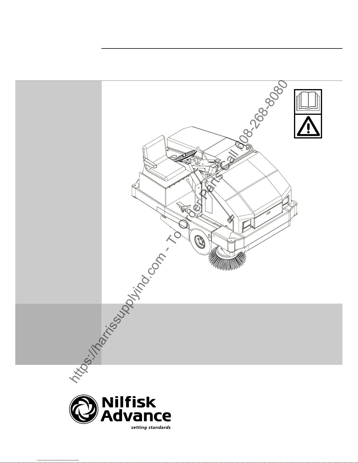
Retriever™ 2060
Advance MODELS 56418000(propane),
56418001(gas), 56418002(dual fuel),
56418003(diesel)
Instructions For Use
Instrucciones de uso
https://harrissupplyind.com - To Order Parts Call 608-268-8080
Page 2

FORM NO. 56041432 / 2060 - 3
TABLE OF CONTENTS
Page
Introduction ............................................................................................. 4
Parts and Service.................................................................................... 4
Nameplate............................................................................................... 4
Uncrating the Machine ............................................................................ 4
Cautions and Warnings........................................................................... 6
General Information ................................................................................ 8
Know Your Machine ......................................................................... 10-13
Preparing the Machine for Use
Pre-Operational Checklist ..................................................................... 18
Fuel ....................................................................................................... 18
Operating the Machine
Starting the Gasoline Engine ................................................................ 20
Starting the Propane Engine ................................................................. 20
Starting the Dual Fuel Engine ............................................................... 20
Starting the Diesel Engine .................................................................... 20
Sweeping .............................................................................................. 22
Emptying the Hopper ............................................................................ 22
After Using the Machine
After Use ............................................................................................... 24
Shutting Down the Gasoline Engine ..................................................... 24
Shutting Down the Propane Engine ...................................................... 24
Shutting Down the Dual Fuel Engine .................................................... 24
Shutting Down the Diesel Engine ......................................................... 24
Maintenance
Every 15 Hours of Operation ................................................................ 25
Every 30 Hours of Operation ................................................................ 25
Every 150 Hours of Operation .............................................................. 25
Every 300 Hours of Operation .............................................................. 25
Every 1000 Hours of Operation ............................................................ 25
Side Broom Maintenance...................................................................... 27
Main Broom Maintenance ..................................................................... 28
Hopper Dust Control Filter .................................................................... 30
Parking Brake Lever Adjustment .......................................................... 31
Engine Oil ............................................................................................. 31
Engine Air Filter .................................................................................... 31
Circuit Breaker Location........................................................................ 31
Troubleshooting ............................................................................... 33-34
Technical Specifications ....................................................................... 35
ÍNDICE
Página
Introducción ............................................................................................ 5
Componentes y servicio.......................................................................... 5
Placa de identificación ............................................................................ 5
Desembalaje de la máquina ................................................................... 5
Precauciones y advertencias .................................................................. 7
Información general ................................................................................ 9
Conozca su máquina ....................................................................... 10-13
Preparación de la máquina para su utilización
Comprobaciones previas a la utilización ............................................... 19
Combustible .......................................................................................... 19
Funcionamiento de la máquina
Encendido del motor de gasolina .......................................................... 21
Encendido del motor de propano .......................................................... 21
Encendido del motor de combustible doble .......................................... 21
Encendido del motor Diesel .................................................................. 21
Barrido .................................................................................................. 23
Vaciado de la tolva................................................................................ 23
Después de la utilización de la máquina
Después de la utilización ...................................................................... 24
Para apagar el motor de gasolina ......................................................... 24
Para apagar el motor de propano ......................................................... 24
Para apagar el motor de combustible doble ......................................... 24
Apagado del motor Diesel ..................................................................... 24
Mantenimiento
Cada 15 horas de funcionamiento ........................................................ 26
Cada 30 horas de funcionamiento ........................................................ 26
Cada 150 horas de funcionamiento ...................................................... 26
Cada 300 horas de funcionamiento ...................................................... 26
Cada 1.000 horas de funcionamiento ................................................... 26
Mantenimiento del cepillo lateral........................................................... 27
Mantenimiento del cepillo principal ....................................................... 29
Filtro de control de polvo de la tolva ..................................................... 30
Ajuste de la palanca del freno de estacionamiento .............................. 32
Aceite del motor .................................................................................... 32
Filtro del aire del motor ......................................................................... 32
Ubicación de los disyuntores ................................................................ 32
Localización de averías ................................................................... 33-34
Especificaciones técnicas ..................................................................... 35
https://harrissupplyind.com - To Order Parts Call 608-268-8080
Page 3

4 - FORM NO. 56041432 / 2060
INTRODUCTION
This manual will help you get the most from your Nilfisk-Advance 2060. Read it thoroughly before operating the machine.
Note: Bold numbers in parentheses indicate an item illustrated on pages 10-13.
PARTS AND SERVICE
Repairs, when required, should be performed by your Authorized Nilfisk-Advance Service Center, who employs factory trained service personnel, and maintains
an inventory of Nilfisk-Advance original replacement parts and accessories.
Call the NILFISK-ADVANCE DEALER named below for repair parts or service. Please specify the Model and Serial number when discussing your machine.
NAME PLATE
The Model and Serial Number of your machine are shown on the Nameplate on the right side of the machine. This information is needed when ordering repair
parts for the machine. Use the space below to note the Model and Serial Number of your machine for future reference.
MODEL
SERIAL NUMBER
UNCRATING THE MACHINE
When the machine is delivered, carefully inspect the shipping carton and the machine for damage. If damage is evident, save the shipping carton so that it can
be inspected. Contact the Nilfisk-Advance Customer Service Department immediately to file a freight damage claim.
1 After removing the crate, remove the wooden blocks next to the wheels.
2 Check the engine oil level, add oil if necessary.
3 Check the engine coolant level, add coolant if necessary.
4 Check the hydraulic oil level, add oil if necessary.
5 Read the instructions in the Preparing the Machine For Use section of this manual, then fill the fuel tank.
6 Place a ramp next to the front end of the pallet.
7 Read the instructions in the Operating Controls and Operating the Machine sections of this manual and start the engine. Slowly drive the machine forward
from the pallet to the floor. Keep your foot lightly on the brake pedal until the machine is off the pallet.
CAUTION!
Use extreme CAUTION when operating this sweeper. Be certain that you are thoroughly familiar with all of the operating instructions
prior to using this sweeper. If you have any questions, contact your supervisor or your local Nilfisk-Advance Industrial Dealer.
Should your sweeper malfunction, do not attempt to correct the problem unless your supervisor directs you to do so. Have a qualified
company mechanic or an authorized Nilfisk-Advance Dealer Service person make any necessary corrections to the equipment.
Use extreme care when working on this machine. Neckties, loose clothing, long hair, rings and bracelets can get caught in moving
parts. Turn the Key Switch (52) OFF, set the Parking Brake (3) and disconnect the battery before working on the machine. Use good
common sense, practice good safety habits and pay attention to the yellow decals on this machine.
MODEL ENGINE ENGINE
NUMBER MAKE MODEL NUMBER FUEL
56418001 Ford VSG 413I-6005-A GASOLINE (G)
56418000 Ford VSG 413I-6005-A PROPANE (P)
56418002 Ford VSG 413I-6005-A DUAL FUEL (DU)
56418003 Kubota V1505TE-1 DIESEL (D)
* Note: Reference the separately supplied engine manufacture’s maintenance and operator manual for more detailed engine specification and service data.
https://harrissupplyind.com - To Order Parts Call 608-268-8080
Page 4

FORM NO. 56041432 / 2060 - 5
INTRODUCCIÓN
Este manual le ayudará a sacar el mejor partido a su Nilfisk-Advance 2060. Léalo con atención antes de utilizar la máquina.
Nota: Los números que aparecen en negrita entre paréntesis indican elementos ilustrados en las páginas 10-13.
COMPONENTES Y SERVICIO
Las reparaciones, en caso necesario, deben ser realizadas por el personal de servicio de Nilfisk-Advance con los repuestos y accesorios originales de NilfiskAdvance.
Para repuestos o servicio, póngase en contacto con Nilfisk-Advance, indicando el Modelo y Número de Serie de la máquina.
PLACA DE IDENTIFICACIÓN
El Modelo y el Número de Serie de la máquina están indicados en la Placa de identificación situada en el lado derecho de la máquina. Esta información es necesaria
a la hora de solicitar repuestos para la máquina. Utilice el siguiente espacio para anotar el Modelo y el Número de Serie de su máquina para futuras consultas.
MODELO
NÚMERO DE SERIE
DESEMBALAJE DE LA MÁQUINA
Cuando reciba la máquina, examine con atención el cartón de embalaje y la máquina, con el fin de comprobar si existe algún daño. Si observa algún daño, guarde
el cartón de embalaje para que lo pueda examinar el transportista que lo entregó. Póngase en contacto con el transportista inmediatamente para presentar una
reclamación por daño durante el transporte.
1 Después de retirar la caja, retire los bloques de madera situados junto a las ruedas.
2 Compruebe el nivel de aceite del motor y añada aceite si es necesario.
3 Compruebe el nivel del líquido de refrigeración del motor y añada líquido de refrigeración si es necesario.
4 Compruebe el nivel de aceite hidráulico y añada aceite si es necesario.
5 Lea las instrucciones de la sección “Preparación de la máquina para su utilización” de este manual y llene el depósito de combustible.
6 Coloque una rampa junto al extremo delantero de la tarima de carga.
7 Lea las instrucciones de las secciones “Funcionamiento de los controles” y “Funcionamiento de la máquina” de este manual y encienda el motor. Conduzca
despacio la máquina desde la tarima de transporte hasta el suelo. Mantenga el pie pisando ligeramente el pedal del freno hasta que la máquina haya
bajado de la tarima.
¡PRECAUCIÓN!
Extreme las PRECAUCIONES al utilizar esta barredora. Antes de utilizarla, debe conocer bien todas sus instrucciones de
funcionamiento. Si tiene alguna duda, consulte con su supervisor o con su Proveedor Industrial local Nilfisk-Advance.
En caso de funcionamiento incorrecto de su barredora, no intente solucionar el problema a menos que se lo ordene su supervisor.
Solicite la ayuda de un mecánico cualificado de su empresa o de una persona autorizada por el Servicio del Proveedor NilfiskAdvance para que efectúen las correcciones necesarias en el equipo.
Extreme las precauciones al utilizar esta máquina. Existe el peligro de que las corbatas, prendas sueltas, pelo largo, anillos y pulseras
queden atrapados entre los componentes móviles. Apague el interruptor de llave (52), eche el freno de estacionamiento (3) y
desconecte la batería antes de utilizar la máquina. Utilice el sentido común, respete las normas de seguridad y preste atención a l as
pegatinas amarillas colocadas en la máquina.
NÚMERO DE MARCA DEL NÚMERO DE MODELO
MODELO MOTOR DEL MOTOR COMBUSTIBLE
56418001 Ford VSG 413I-6005-A GASOLINA (G)
56418000 Ford VSG 413I-6005-A PROPANO (P)
56418002 Ford VSG 413I-6005-A COMBUSTIBLE DOBLE (DU)
56418003 Kubota V1505TE-1 DIESEL (D)
* Nota: Si desea datos más detallados sobre especificaciones y servicio del motor, consulte el manual de utilización y mantenimiento del motor elaborado por
el fabricante y entregado por separado.
https://harrissupplyind.com - To Order Parts Call 608-268-8080
Page 5

6 - FORM NO. 56041432 / 2060
CAUTIONS AND WARNINGS
SYMBOLS
Nilfisk-Advance uses the symbols below to signal potentially dangerous conditions. Always read this information carefully and take
the necessary steps to protect personnel and property.
DANGER !
Is used to warn of immediate hazards that will cause severe personal injury or death.
WARNING !
Is used to call attention to a situation that could cause severe personal injury.
CAUTION !
Is used to call attention to a situation that could cause minor personal injury or damage to the machine or other property.
GENERAL SAFETY INSTRUCTIONS
Specific Cautions and Warnings are included to warn you of potential danger of machine damage or bodily harm.
WARNING !
* This machine shall be used only by properly trained and authorized persons.
* While on ramps or inclines, avoid sudden stops when loaded. Avoid abrupt sharp turns. Use low speed down hills. Clean
only while ascending (driving up) the ramp.
* To avoid hydraulic oil injection or injury always wear appropriate clothing and eye protection when working with or near
hydraulic system.
* Turn the key switch off (O) and disconnect the battery before servicing electrical components.
* Never work under a machine without safety blocks or stands to support the machine.
* Do not dispense flammable cleaning agents, operate the machine on or near these agents, or operate in areas where
flammable liquids exist.
* Do not clean this machine with a pressure washer.
* This machine emits exhaust gases (carbon monoxide) that can cause serious injury or death, always provide adequate
ventilation when using machine.
CAUTION !
* This machine is not approved for use on public paths or roads.
* This machine is not suitable for picking up hazardous dust.
* When operating this machine, ensure that third parties, particularly children, are not endangered.
* Before performing any service function, carefully read all instructions pertaining to that function.
* Do not leave the machine unattended without first turning the key switch off (O), removing the key and applying the parking
brake.
* Turn the key switch off (O) before changing the brushes, and before opening any access panels.
* Take precautions to prevent hair, jewelry, or loose clothing from becoming caught in moving parts.
SAVE THESE INSTRUCTIONS
https://harrissupplyind.com - To Order Parts Call 608-268-8080
Page 6

FORM NO. 56041432 / 2060 - 7
PRECAUCIONES Y ADVERTENCIAS
SÍMBOLOS
Nilfisk-Advance utiliza los símbolos que aparecen a continuación para indicar situaciones potencialmente peligrosas. Lea siempre
con atención esta información y tome las medidas necesarias para la protección del personal y los objetos.
¡PELIGRO!
Se utiliza para advertir de peligros inmediatos que pueden producir graves daños personales o la muerte.
¡ADVERTENCIA!
Se utiliza para llamar la atención sobre una situación que puede causar graves daños personales.
¡PRECAUCIÓN!
Se utiliza para llamar la atención sobre una situación que puede causar daños personales leves o daños a la máquina u otros objetos.
INSTRUCCIONES GENERALES DE SEGURIDAD
Se incluyen Precauciones y Advertencias específicas que le advierten de los posibles riesgos de daño a la máquina o daño corporal.
¡ADVERTENCIA!
Sólo deben utilizar esta máquina las personas autorizadas y con la formación adecuada.
Si se encuentra sobre una rampa o inclinación, evite las paradas bruscas cuando lleve carga. No tome las curvas bruscamente.
Utilice una velocidad lenta si va cuesta abajo. Limpie sólo yendo cuesta arriba.
Para evitar la inyección de aceite hidráulico o los daños, lleve siempre la vestimenta adecuada y protección ocular cuando
trabaje con el sistema hidráulico o cerca de él.
Apague el interruptor de llave (O) y desconecte la batería antes de realizar operaciones de servicio de los componentes
eléctricos.
No trabaje nunca debajo de la máquina sin colocar antes bloques o soportes de seguridad en los que apoyar la máquina.
No aplique sustancias limpiadoras inflamables ni utilice la máquina sobre estas sustancias, cerca de ellas, ni en zonas en las
que haya líquidos inflamables.
No lave la máquina con una limpiadora a presión.
Esta máquina despide gases de escape (monóxido de carbono) que pueden producir daños graves o la muerte. Disponga
siempre la ventilación adecuada cuando utilice la máquina.
¡PRECAUCIÓN!
Esta máquina no ha sido aprobada para su uso en vías públicas.
Esta máquina no es apta para la recogida de polvo peligroso.
Cuando utilice la máquina, asegúrese de que no existe peligro para terceras personas, especialmente niños.
Antes de proceder a cualquier función de servicio, lea con atención todas las instrucciones relativas a dicha función.
No abandone la máquina sin antes apagar el interruptor de llave (O), retirar la llave y echar el freno de estacionamiento.
Apague el interruptor de llave (O) antes de cambiar los cepillos y antes de abrir cualquiera de los paneles de acceso.
Tome las debidas precauciones para evitar que el pelo, las joyas o las prendas sueltas queden atrapados entre los
componentes móviles.
GUARDE ESTAS INSTRUCCIONES
https://harrissupplyind.com - To Order Parts Call 608-268-8080
Page 7

8 - FORM NO. 56041432 / 2060
A
B
HOPPER SAFETY SUPPORT
WARNING!
Make sure the Hopper Safety Support (5) is in place whenever attempting to do any maintenance work under or near the raised hopper.
The Hopper Safety Support (5) holds the hopper in the raised position to allow work to be performed under the hopper. NEVER rely
on the machine’s hydraulic components to safely support the hopper.
JACKING THE MACHINE
CAUTION!
Never work under a machine without safety stands or blocks to support the machine.
• When jacking the machine, do so at designated locations (Do Not jack on the hopper) - see jacking locations (25).
TRANSPORTING THE MACHINE
CAUTION!
Before transporting the machine on an open truck or trailer, make sure that...
• All access doors are latched securely
• The machine is tied down securely.
• The machine parking brake is set.
TOWING OR PUSHING A DISABLED MACHINE
The machine’s drive propelling pump is manufactured with an adjustable tow valve. This valve prevents damage to the hydraulic system when the machine is
being towed/pushed short distances without use of the engine.
To access the valve open the left front door panel and locate the valve as shown on
top rear of the propelling pump. Use a pliers or 5/16” (8 mm) open end wrench
to turn the valve 90 degrees, this disengages the hydrostatic lock between the motor and pump.
WARNING: The hydraulic propelling pump can be damaged if the machine is towed with the valve in the normal working position (A). Reference the illustrations
below for the normal working setting (A) (vertical) and the free wheeling towing setting (B) (horizontal). Note: If the tow valve is left in free wheeling (B) (horizontal)
position the propelling pump can’t drive the machine FWD or REV. No damage will result, just re-set valve to the normal working setting (A) (vertical). NOTE:
Tow or push machine no faster than a normal walking pace (2-3 miles per hour) and for short distances only. If the machine is to be moved long distances the
drive wheel needs to be raised off the floor and placed on a suitable transport dolly.
https://harrissupplyind.com - To Order Parts Call 608-268-8080
Page 8

FORM NO. 56041432 / 2060 - 9
A
B
SOPORTE DE SEGURIDAD DE LA TOLVA
¡ADVERTENCIA!
Compruebe que el Soporte de Seguridad de la Tolva (5) se encuentra colocado cuando vaya a realizar alguna operación de
mantenimiento debajo de la tolva levantada o cerca de ella. El Soporte de Seguridad de la Tolva (5) mantiene la tolva en posición
elevada para permitir la realización de operaciones debajo de la tolva. No se limite NUNCA a los componentes hidráulicos de la
máquina solamente para soportar la tolva de manera segura.
ELEVACIÓN DE LA MÁQUINA
¡PRECAUCIÓN!
No trabaje nunca debajo de la máquina sin colocar antes los soportes o bloques de seguridad para apoyar la máquina.
• Cuando eleve la máquina, aplique los gatos en los lugares indicados (No en la tolva) – véase puntos de elevación (25).
TRANSPORTE DE LA MÁQUINA
¡PRECAUCIÓN!
Antes de transportar la máquina sobre un camión o remolque abierto, asegúrese de...
• cerrar bien todas las puertas de acceso
• sujetar bien la máquina, de forma que quede segura
• echar el freno de estacionamiento de la máquina.
REMOLQUE O EMPUJE DE LA MÁQUINA EN CASO DE AVERÍA
La bomba de propulsión de transmisión de la máquina lleva una válvula de remolque ajustable, que impide que se produzcan daños en el sistema hidráulico en
caso de que deba remolcarse/empujarse la máquina una distancia corta sin el uso del motor.
Para acceder a la válvula, abra la puerta del panel delantero izquierdo y localice la válvula, según se indica, en la
parte trasera superior de la bomba de propulsión.
Utilice unos alicates o una llave con una abertura de 8 mm para girar la válvula 90 grados. De esta forma desacoplará el bloqueo hidrostático entre el motor y
la bomba.
ADVERTENCIA: La bomba de propulsión hidráulica puede sufrir daños si se remolca la máquina con la válvula en posición normal de funcionamiento (A). Consulte
en las ilustraciones que aparecen más adelante el ajuste normal de funcionamiento (A) (vertical) y el ajuste de giro libre para remolque (B) (horizontal). Nota:
si la válvula de remolque se deja en posición de giro libre (B) (horizontal), la bomba de propulsión no podrá desplazar la máquina hacia delante ni hacia atrás.
No se producirá ningún daño; sólo tiene que volver a situar la válvula en el ajuste normal de funcionamiento (A) (vertical). NOTA: No remolque ni empuje la máquina
a una velocidad superior a la del paso normal de una persona (3-5 km/h) y hágalo solamente en distancias cortas. Si necesita desplazar la máquina una larga
distancia, la rueda motriz debe elevarse del suelo y colocarse sobre un gato rodante.
https://harrissupplyind.com - To Order Parts Call 608-268-8080
Page 9
10 - FORM NO. 56041432 / 2060
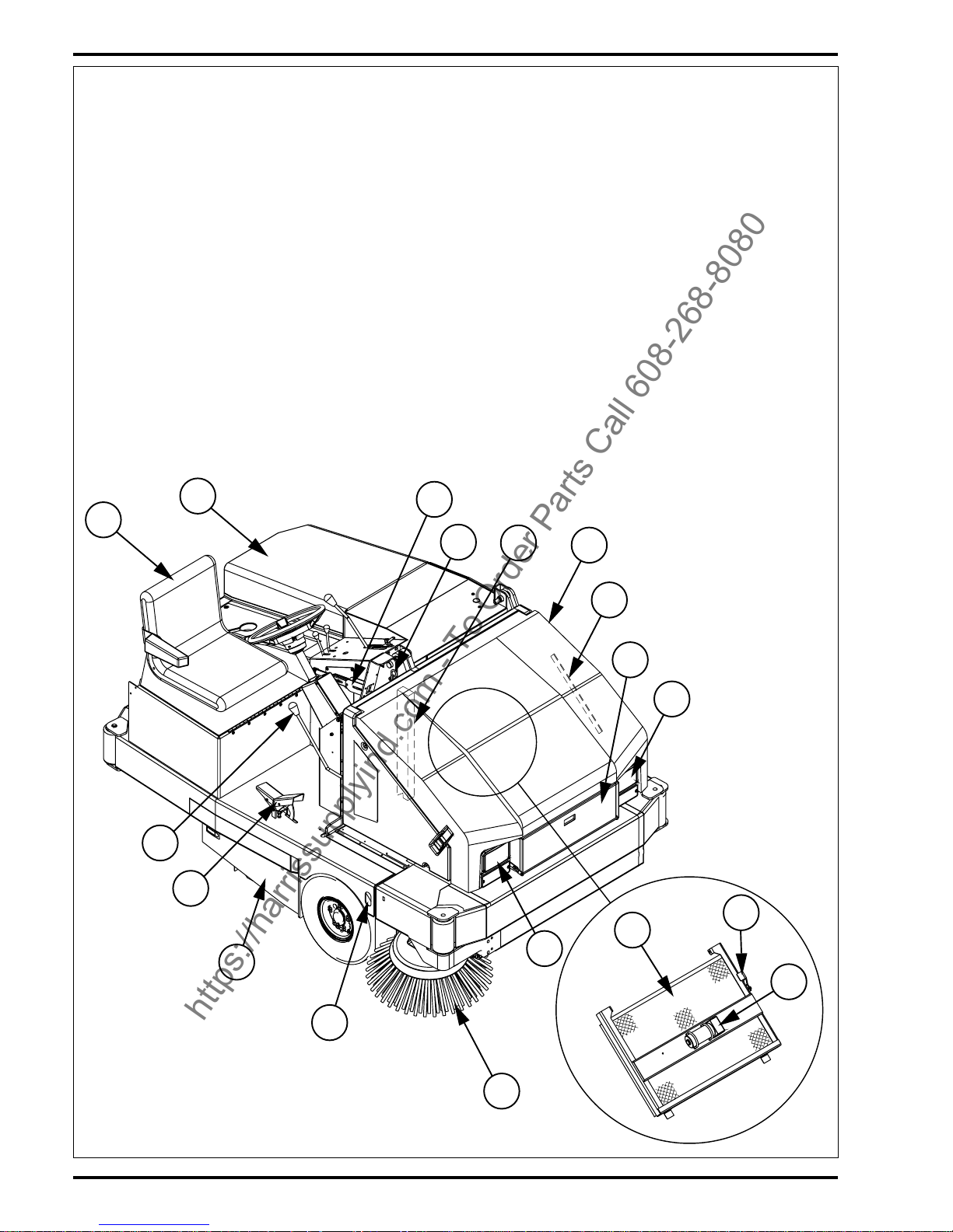
KNOW YOUR MACHINE
As you read this manual, you will occasionally run across a bold number in
parentheses - example: (2). These numbers refer to an item on the next three
pages. Refer back to these pages whenever necessary to pinpoint the location
of an item mentioned in the text.
1 Operator’s Seat
2 Engine Cover
3 Parking Brake Lever (Foot Brake)
4 Hopper Safety Support Pull Rod
5 Hopper Safety Support
6 Hopper Cover
7 Hopper Cover Prop Rod
8 Litter Door
9 Head Light
10 Hopper Dust Control Filter
11 Shaker Assembly Latch
12 Dust Filter Shaker Assembly
13 Side Broom
14 Tie Down Point
15 Main Broom Access Door
16 FWD / REV Drive Pedal
17 Side Broom Raise / Lower (ON / OFF) Lever
18 Hopper Cover Latch
1
2
3
4
5
6
7
9
8
10
11
12
9
13
14
15
16
17
CONOZCA SU MÁQUINA
A lo largo de este manual encontrará números en negrita entre paréntesis – por
ejemplo: (2). Estos números se refieren a uno de los elementos que aparecen
en las siguientes tres páginas. Consulte estas páginas siempre que lo necesite
para localizar los elementos citados en el texto.
1 Asiento del operador
2 Cubierta del motor
3 Palanca de freno de estacionamiento (Freno de pie)
4 Varilla de tiro del soporte de seguridad de la tolva
5 Soporte de seguridad de la tolva
6 Cubierta de la tolva
7 Varilla de apoyo de la cubierta de la tolva
8 Puerta de la basura
9 Faro delantero
10 Filtro de control de polvo de la tolva
11 Pestillo del conjunto del agitador
12 Agitador del filtro de polvo
13 Cepillo lateral
14 Punto de sujeción
15 Puerta de acceso al cepillo principal
16 Pedal de tracción hacia delante/hacia atrás
17 Palanca de elevación/descenso (ON / OFF) del cepillo lateral
18 Pestillo de la cubierta de la tolva
https://harrissupplyind.com - To Order Parts Call 608-268-8080
Page 10

FORM NO. 56041432 / 2060 - 11
18
19
20
21
22
23
24
25
14
14
26
27
30
29
31
32
33
14
25
28
35
19 Battery
20 Tilt Wheel Lever
21 Steering Wheel
22 Oil Reservoir
23 Propane Tank
24 Fuel Tank
25 Jacking Locations
26 Engine Oil Drain
27 Muffler
28 Coolant Recovery Tank
29 Engine Oil Dipstick
30 Engine Air Filter
31 Engine Access Door
32 Circuit Breaker / Battery Compartment Door
33 Circuit Breaker Panel
34 Horn Button (Not Shown / Found Below Brake Pedal)
35 Control Panel (see associated pages)
19 Batería
20 Palanca de inclinación del volante
21 Volante
22 Depósito del aceite
23 Depósito de propano
24 Depósito de combustible
25 Puntos de elevación
26 Drenaje del aceite del motor
27 Silenciador
28 Depósito de recuperación del líquido de refrigeración
29 Varilla medidora del aceite del motor
30 Filtro del aire del motor
31 Puerta de acceso al motor
32 Puerta del compartimento de los disyuntores / batería
33 Panel de disyuntores
34 Botón del claxon (No aparece en la ilustración / Debajo del pedal
del freno)
35 Panel de control (véanse las páginas correspondientes)
https://harrissupplyind.com - To Order Parts Call 608-268-8080
Page 11

12 - FORM NO. 56041432 / 2060
CONTROL PANEL
36 Oil Pressure Gauge (optional)
37 Battery Meter (optional)
38 Fuel Gauge (Gas, Dual Fuel and Diesel Only)
39 Hourmeter
40 Dust Control / Shaker Switch
41 Headlight Switch
42 Engine Speed Switch (Gas, LP and Dual Fuel Only)
43 Dump Door Indicator Light
44 Check Engine Indicator Light
45 Engine Temperature Indicator Light
46 Battery Indicator Light
47 Oil Pressure Indicator Light
48 Dust Control Filter Indicator Light (optional)
49 Hopper Temperature Indicator Light (optional)
50 Hydraulic Filter Indicator Light
51 Propane Fuel Low Indicator Light
52 Ignition Key Switch
53 Main Broom Raise / Lower (ON /OFF) Lever
54 Fuel Selector (Dual Fuel Only)
55 Hopper Raise / Lower Lever
56 Hopper Door Open / Close Lever
57 Water Temp. Gauge (optional)
58 Air Filter Service Indicator
59 Glow Plug Indicator Light (Diesel Only)
60 Throttle Control (Diesel Only)
PANEL DE CONTROL
36 Manómetro del aceite (opcional)
37 Medidor de la batería (opcional)
38 Indicador de nivel del combustible (sólo gasolina, dos combus-
tibles y Diesel)
39 Contador horario
40 Interruptor del agitador / control de polvo
41 Interruptor de los faros
42 Cambio de velocidad del motor (sólo gasolina, BP y dos combus-
tibles)
43 Luz indicadora de la puerta de descarga
44 Luz indicadora de comprobación del motor
45 Luz indicadora de temperatura del motor
46 Luz indicadora de la batería
47 Luz indicadora de la presión del aceite
48 Luz indicadora del filtro de control de polvo (opcional)
49 Luz indicadora de la temperatura de la tolva (opcional)
50 Luz indicadora del filtro hidráulico
51 Luz indicadora de nivel bajo del propano
52 Interruptor de llave de encendido
53 Palanca de elevación/descenso (ON /OFF) del cepillo principal
54 Selector de combustible (Sólo combustible doble)
55 Palanca de elevación/descenso de la tolva
56 Palanca de apertura/cierre de la puerta de la tolva
57 Indicador de la temperatura del agua (opcional)
58 Indicador de servicio del filtro del aire
59 Luz indicadora del tapón encendedor (sólo Diesel)
60 Control del acelerador (sólo Diesel)
https://harrissupplyind.com - To Order Parts Call 608-268-8080
Page 12

FORM NO. 56041432 / 2060 - 13
43
44
45
46
47
48
49
50
51
59
57
36
38
40
42
41
39
37
54
58
53
55
56
52
57
36
38
41
40
39
37
60
58
53
55
56
52
2060G, P, DU
2060D
https://harrissupplyind.com - To Order Parts Call 608-268-8080
Page 13

14 - FORM NO. 56041432 / 2060
KNOW YOUR MACHINE DESCRIPTIONS
1 OPERATOR’S SEAT – seat tips forward for access to the hydraulic oil tank and propane tank. Engage prop bar for safety.
2 ENGINE COVER – unlatch and raise to access engine compartment.
3 PARKING BRAKE LEVER (FOOT BRAKE) – operates the mechanical brakes on the front wheels.
4 HOPPER SAFETY SUPPORT PULL ROD – pull up on rod while hopper is raised to pull safety support into place.
5 HOPPER SAFETY SUPPORT – used to support the hopper while raised.
6 HOPPER COVER – open to access the hopper dust control filter.
7 HOPPER COVER PROP ROD – used to support the hopper cover while raised.
8 LITTER DOOR – throw debris in here that is too large for the broom to pick up.
9 HEAD LIGHT – use when sweeping in hard to see areas.
10 HOPPER DUST CONTROL FILTER – filters dust from the air.
11 SHAKER ASSEMBLY LATCH – used to hold the shaker assembly UP while servicing the filter.
12 DUST FILTER SHAKER ASSEMBLY – vibrates the dust control filter to shake dust out of it.
13 SIDE BROOM – used for sweeping along walls or curbs.
14 TIE DOWN POINT – safe point to tie down machine when transporting via trailer or truck.
15 MAIN BROOM ACCESS DOOR – open to access main broom for servicing.
16 FORWARD/REVERSE DRIVE PEDAL – controls the machine’s travel speed and direction:
Push down on the Back of the pedal to move the machine Backward.
Push down on the Front of the pedal to move the machine Forward.
The SPEED of the machine will increase as the pedal is pushed closer to the floor. Maximum forward speed is faster than maximum reverse speed.
17 SIDE BROOM RAISE/LOWER (ON/0FF) LEVER – raises or lowers (stops and starts) the side broom.
18 HOPPER COVER LATCH – holds hopper cover in place.
19 BATTERY – provides electrical power for starting engine.
20 TILT WHEEL LEVER – push lever down to release steering column for adjusting up or down.
21 STEERING WHEEL – used to steer machine left or right.
22 OIL RESERVOIR – holds the hydraulic system oil, 11 gallon (41.63 liter) capacity.
23 PROPANE FUEL TANK – 33 lb. liquid withdrawal propane tank.
24 FUEL TANK – 12 gallon (45 liter) capacity
25 JACKING LOCATIONS – safe points for jacking machine up.
26 ENGINE OIL DRAIN – location of engine oil drain plug (under rear bumper).
27 MUFFLER – muffles engine exhaust.
28 COOLANT RECOVERY TANK – recovers coolant pushed out of radiator while engine is hot, used for checking coolant level.
29 ENGINE OIL DIPSTICK – used to check engine oil level.
30 ENGINE AIR FILTER – filters engine’s intake air supply.
31 ENGINE ACCESS DOOR – unlatch and open to access engine compartment.
32 CIRCUIT BREAKER / BATTERY COMPARTMENT DOOR – unlatch and open to access circuit breakers, battery & engine air filter.
33 CIRCUIT BREAKER PANEL – location of all machine circuit breakers.
34 HORN BUTTON – sounds the horn (directly below the brake pedal).
35 CONTROL PANEL – See associated pages.
https://harrissupplyind.com - To Order Parts Call 608-268-8080
Page 14

FORM NO. 56041432 / 2060 - 15
CONTROL PANEL DESCRIPTIONS
36 OIL PRESSURE GAUGE (OPTIONAL) – indicates the engine oil pressure while the engine is running.
37 BATTERY METER (OPTIONAL) – indicates the level of battery voltage and charging voltage.
38 FUEL GAUGE (GAS, DUAL FUEL AND DIESEL ONLY) – indicates the amount of fuel in the fuel tank.
39 HOUR METER – indicates the accumulated hours of usage.
40 DUST CONTROL SHAKER SWITCH – controls the vacuum system and the vacuum filter shaker. The vacuum system picks up dust raised by the main
broom. The filter shaker cleans the vacuum filter.
41 HEADLIGHT SWITCH – turns on the headlights.
42 ENGINE SPEED SWITCH (GAS, LP AND DUAL FUEL ONLY) – controls the speed of the engine. When operating the machine, the engine speed switch
should be in the full throttle position (lll).
43 DUMP DOOR INDICATOR LIGHT – indicates that dump door is closed or the hopper is raised.
44 CHECK ENGINE INDICATOR LIGHT (Currently N/A) – indicates a malfunction of the EFI system, shut off engine and have your Nilfisk-Advance Service
Center check the machine.
45 ENGINE TEMPERATURE INDICATOR LIGHT – indicates engine overheating, comes on at 225° F (107° C), engine shuts itself off at 235° F (113° C).
Turn key off and have your Nilfisk-Advance Service Center check the machine.
46 BATTERY INDICATOR LIGHT – indicates a charging system malfunction, shut off engine and have your Nilfisk-Advance Service Center check the
machine.
47 OIL PRESSURE INDICATOR LIGHT – indicates loss of engine oil pressure, 10 seconds after the light comes on, the engine will shut itself off. Turn key
off and have your Nilfisk-Advance Service Center check the machine.
48 DUST CONTROL FILTER INDICATOR LIGHT (OPTIONAL) – indicates when the dust control filter should be serviced.
49 HOPPER TEMPERATURE INDICATOR LIGHT (OPTIONAL) – indicates potential fire in the hopper.
50 HYDRAULIC FILTER INDICATOR LIGHT – indicates when the hydraulic oil filter should be serviced. Have your Nilfisk-Advance Service Center check
the machine.
51 PROPANE FUEL LOW INDICATOR LIGHT – indicates low propane fuel level.
52 IGNITION KEY SWITCH – controls the engine and some parts of the electrical system.
53 MAIN BROOM RAISE / LOWER (ON/OFF) LEVER – raises and lowers (stops and starts) the main sweeping broom. The sweep position is for smooth
floors. The full float position is for rough floors.
54 FUEL SELECTOR – found on dual fuel model only, to switch between propane and gasoline.
55 HOPPER RAISE/LOWER LEVER – controls the hydraulic cylinder that raises the hopper for dumping.
56 HOPPER DOOR OPEN / CLOSE LEVER – opens and closes the hopper dump door.
57 WATER TEMPERATURE GAUGE (OPTIONAL) – indicates the temperature of the engine coolant while the engine is running.
58 AIR FILTER SERVICE INDICATOR – Do not service the air filter unless the red flag is visible in the service indicator.
59 GLOW PLUG INDICATOR LIGHT (DIESEL ONLY) - indicates that the glow plugs are warming up, start engine after light goes out.
60 THROTTLE CONTROL (DIESEL ONLY) - controls the speed of the diesel engine. When operating the machine, the engine speed switch should be in
the full throttle (rabbit) position.
https://harrissupplyind.com - To Order Parts Call 608-268-8080
Page 15

16 - FORM NO. 56041432 / 2060
CONOZCA LAS DESCRIPCIONES DE SU MÁQUINA
1 ASIENTO DEL OPERADOR – el asiento se inclina hacia delante para permitir el acceso al depósito del aceite hidráulico y al depósito de propano. Para
su seguridad, coloque la barra de soporte.
2 CUBIERTA DEL MOTOR – abra y levante para acceder al compartimento del motor.
3 PALANCA DEL FRENO DE ESTACIONAMIENTO (FRENO DE PIE) – acciona los frenos mecánicos de las ruedas delanteras.
4 VARILLA DE TIRO DEL SOPORTE DE SEGURIDAD DE LA TOLVA – tire de la varilla cuando eleve la tolva para colocar el soporte de seguridad.
5 SOPORTE DE SEGURIDAD DE LA TOLVA – sirve de soporte a la tolva cuando ésta se encuentra levantada.
6 CUBIERTA DE LA TOLVA – abra para acceder al filtro de control de polvo de la tolva.
7 VARILLA DE APOYO DE LA CUBIERTA DE LA TOLVA - sirve de soporte a la cubierta de la tolva cuando ésta se encuentra levantada.
8 PUERTA DE LA BASURA – deposite aquí los residuos que sean demasiado grandes para que los pueda recoger el cepillo.
9 FARO DELANTERO – se utiliza para barrer zonas en las que no se vea bien.
10 FILTRO DE CONTROL DE POLVO DE LA TOLVA – filtra el polvo del aire.
11 PESTILLO DEL CONJUNTO DEL AGITADOR – sirve para mantener elevado el conjunto del agitador mientras se realizan operaciones de servicio en
el filtro.
12 AGITADOR DEL FILTRO DE POLVO – hace vibrar el filtro de control de polvo para quitar el polvo.
13 CEPILLO LATERAL – sirve para barrer a lo largo de paredes o bordillos.
14 PUNTO DE SUJECIÓN – punto de seguridad por donde sujetar la máquina para su transporte en un camión o remolque.
15 PUERTA DE ACCESO AL CEPILLO PRINCIPAL – abra para acceder al cepillo principal para operaciones de servicio.
16 PEDAL DE TRACCIÓN HACIA DELANTE/HACIA ATRÁS – controla la velocidad y la dirección de la máquina:
Puse la parte trasera del pedal para desplazar la máquina hacia atrás.
Puse la parte delantera del pedal para desplazar la máquina hacia delante.
La VELOCIDAD de la máquina aumentará cuanto más a fondo se pise el pedal. La velocidad máxima hacia delante es más rápida que la velocidad máxima
hacia atrás.
17 PALANCA DE ELEVACIÓN/DESCENSO (ON/0FF) DEL CEPILLO LATERAL – eleva o baja (detiene y pone en marcha) el cepillo lateral.
18 PESTILLO DE LA CUBIERTA DE LA TOLVA – mantiene en su lugar la cubierta de la tolva.
19 BATERÍA – proporciona la alimentación eléctrica para encender el motor.
20 PALANCA DE INCLINACIÓN DEL VOLANTE – baje la palanca para soltar la columna de dirección y poder ajustarla hacia arriba o hacia abajo.
21 VOLANTE – sirve para dirigir la máquina hacia la izquierda o la derecha.
22 DEPÓSITO DEL ACEITE – contiene el aceite del sistema hidráulico; capacidad: 41,63 litros.
23 DEPÓSITO DE PROPANO – depósito de propano líquido de retirada de 14,85 Kg
24 DEPÓSITO DE COMBUSTIBLE – 45 litros de capacidad
25 PUNTOS DE ELEVACIÓN – puntos de seguridad para elevar la máquina.
26 DRENAJE DEL ACEITE DEL MOTOR – ubicación del tapón de drenaje del aceite del motor (debajo del parachoques trasero).
27 SILENCIADOR – amortigua el sonido del escape del motor.
28 DEPÓSITO DE RECUPERACIÓN DEL LÍQUIDO DE REFRIGERACIÓN – recupera el líquido de refrigeración expulsado del radiador cuando el motor
está caliente; sirve para comprobar el nivel del líquido de refrigeración.
29 VARILLA MEDIDORA DEL ACEITE DEL MOTOR – sirve para comprobar el nivel del aceite del motor.
30 FILTRO DEL AIRE DEL MOTOR – filtra el aire de admisión del motor.
31 PUERTA DE ACCESO AL MOTOR – abra para acceder al compartimento del motor.
32 PUERTA DEL COMPARTIMENTO DE LOS DISYUNTORES / BATERÍA – abra para acceder a los disyuntores, la batería y el filtro del aire del motor.
33 PANEL DE DISYUNTORES – ubicación de todos los disyuntores de la máquina.
34 BOTÓN DE CLAXON – para tocar el claxon (justo debajo del pedal del freno).
35 PANEL DE CONTROL – Véanse las páginas correspondientes.
https://harrissupplyind.com - To Order Parts Call 608-268-8080
Page 16

FORM NO. 56041432 / 2060 - 17
DESCRIPCIONES DEL PANEL DE CONTROL
36 MANÓMETRO DEL ACEITE (OPCIONAL) – indica la presión del aceite del motor cuando éste se encuentra encendido.
37 MEDIDOR DE LA BATERÍA (OPCIONAL) – indica el nivel del voltaje de la batería y el voltaje de carga.
38 INDICADOR DE NIVEL DEL COMBUSTIBLE (SÓLO GASOLINA, DOS COMBUSTIBLES Y DIESEL) – indica la cantidad de combustible existente en
el depósito de combustible.
39 CONTADOR HORARIO – indica las horas acumuladas de uso.
40 INTERRUPTOR DEL AGITADOR DE CONTROL DE POLVO – controla el sistema de aspiración y el agitador del filtro de aspiración. El sistema de
aspiración absorbe el polvo levantado por el cepillo principal. El agitador del filtro limpia el filtro de aspiración.
41 INTERRUPTOR DE LOS FAROS DELANTEROS – enciende los faros delanteros.
42 CAMBIO DE VELOCIDAD DEL MOTOR (SÓLO GASOLINA, BP Y DOS COMBUSTIBLES) – controla la velocidad del motor. Cuando utilice la máquina,
el cambio de velocidad del motor deberá estar en posición de máxima aceleración (lll).
43 LUZ INDICADORA DE LA PUERTA DE DESCARGA – indica que la puerta de descarga está cerrada o que la tolva se encuentra levantada.
44 LUZ INDICADORA DE CONTROL DEL MOTOR (no disponible en la actualidad) – indica un defecto de funcionamiento del sistema EFI; apague el motor
e inspeccione su máquina en un Centro de Servicio Advance.
45 LUZ INDICADORA DE LA TEMPERATURA DEL MOTOR – indica un recalentamiento del motor; se enciende a los 107° C y el motor se detiene
automáticamente a los 113° C. Apáguelo e inspeccione la máquina en su Centro de Servicio Advance.
46 LUZ INDICADORA DE LA BATERÍA – indica un problema de funcionamiento en el sistema de carga, apague el motor y revise la máquina en un Centro
de Servicio Nilfisk-Advance.
47 LUZ INDICADORA DE LA PRESIÓN DEL ACEITE – indica una pérdida de presión del aceite del motor; 10 segundos después de que se encienda la
luz, el motor se detendrá automáticamente. Apáguelo e inspeccione la máquina en su Centro de Servicio Advance.
48 LUZ INDICADORA DEL FILTRO DE CONTROL DE POLVO (OPCIONAL) – indica que es necesario el servicio del filtro de control de polvo.
49 LUZ INDICADORA DE LA TEMPERATURA DE LA TOLVA (OPCIONAL) – indica la posible existencia de fuego en la tolva.
50 LUZ INDICADORA DEL FILTRO HIDRÁULICO – indica que es necesario el servicio del filtro del aceite hidráulico. Revise la máquina en un Centro de
Servicio Nilfisk-Advance.
51 LUZ INDICADORA DE NIVEL BAJO DEL PROPANO – indica un nivel bajo del propano.
52 INTERRUPTOR DE LLAVE DE ENCENDIDO – controla el motor y ciertas partes del sistema eléctrico.
53 PALANCA DE ELEVACIÓN / DESCENSO (ON/OFF) DEL CEPILLO PRINCIPAL – eleva y baja (detiene y pone en marcha) el cepillo principal de barrido.
La posición de barrido es para suelos lisos. La posición de flotación total es para suelos rugosos.
54 SELECTOR DE COMBUSTIBLE – se encuentra sólo en el modelo de combustible doble y permite elegir entre propano y gasolina.
55 PALANCA DE ELEVACIÓN / DESCENSO DE LA TOLVA – controla el cilindro hidráulico que eleva la tolva para su descarga.
56 PALANCA DE APERTURA / CIERRE DE LA TOLVA – abre y cierra la puerta de descarga de la tolva.
57 INDICADOR DE LA TEMPERATURA DEL AGUA (OPCIONAL) – indica la temperatura del líquido de refrigeración del motor cuando éste se encuentra
encendido.
58 INDICADOR DE SERVICIO DEL FILTRO DEL AIRE – No realice operaciones de servicio en el filtro del aire si no aparece la bandera roja en el indicador
de servicio.
59 LUZ INDICADORA DEL TAPÓN ENCENDEDOR (SÓLO DIESEL) – indica que los tapones encendedores se están calentando; encienda el motor cuando
se apague la luz.
60 CONTROL DEL ACELERADOR (SÓLO DIESEL) – controla la velocidad del motor Diesel. Cuando utilice la máquina, el cambio de velocidad del motor
deberá estar en posición de máxima aceleración (conejo).
https://harrissupplyind.com - To Order Parts Call 608-268-8080
Page 17

18 - FORM NO. 56041432 / 2060
PRE-OPERATIONAL CHECKLIST
Before Each Use:
* Inspect the machine for damage, oil or coolant leaks.
* Squeeze the rubber dust cup on the Engine Air Filter (30) to release built-up dust.
* Check the engine coolant level (28).
* Check the engine oil level (29).
* Check the hydraulic oil level (22).
* Check the Fuel Gauge (38) on the gasoline, dual fuel and diesel models.
* Check the Fuel Gauge located on the LP tank (23) for propane model.
* Check the tire pressure of all three tires, should be 90 psi.
* Check the Air Filter Service Indicator (58).
In the Driver’s Seat:
* Be sure that you understand the operating controls and their functions.
* Adjust the seat to allow easy reach of all controls.
* Insert the Master Key and turn the Ignition Key Switch (52) to the ON position. Check for proper operation of the Horn (37), Hour Meter (39) and Headlights
(41). Turn the Ignition Key Switch (52) OFF.
* Check the Parking Brake Lever (3). The lever must hold firmly its (locked parked ) setting with out easily being released.
(Report all defects immediately to service personnel).
Plan Your Cleaning in Advance:
* Arrange long runs with a minimum of stopping or starting.
* Allow 6 inches of broom path overlap to ensure complete coverage.
* Avoid making sharp turns, bumping into posts, or scraping the side of the machine.
FUEL
WARNING !
• ALWAYS STOP THE ENGINE BEFORE FILLING THE FUEL TANK.
• DO NOT SMOKE WHILE FILLING THE FUEL TANK.
• FILL THE FUEL TANK IN A WELL-VENTILATED AREA.
• DO NOT FILL THE FUEL TANK NEAR SPARKS OR OPEN FLAME.
• USE ONLY THE FUEL SPECIFIED ON THE FUEL TANK DECAL.
MODEL 56418001 (GASOLINE)
On machines with gasoline engines, the fuel tank (24) is located at the rear of the machine. A decal near the filler neck shows the proper fuel to use in the machine.
Before removing the cap from the tank, wipe all dust and dirt from the cap and from around the filler neck to keep the fuel as clean as possible.
Fill the tank with unleaded 87 octane regular gasoline. Fuel Tank capacity is 12 gallons (45 liters). Wipe up any gas spilled on or near the machine immediately!
MODEL 56418000 (PROPANE)
On machines with propane engines, the LP tank (23) is located under the drivers seat. A decal gives information about the proper type of tank to be used on the
machine.
To install the LP tank, tip the Seat Panel forward. Mount a standard 33 pound (14.85 kg) horizontal liquid withdrawal propane tank into the cradle. Align orientating
hole onto pin, lower Seat Panel.
Connect the fuel hose and open the shutoff valve slowly on the tank. Wear gloves when connecting or disconnecting the fuel hose. Shut the propane tank service
valve OFF when the machine is not in use.
MODEL 56418002 (DUAL FUEL, GASOLINE/PROPANE)
Refer to the gasoline and propane sections above for tank locations and instructions. The machine can be operated on either gasoline or propane. Set the Fuel
Selector (54) to the desired fuel and follow the instructions for that fuel. Fuel selection can be changed while the engine is running.
NOTE: The LP fuel hose fitting should be connected to an LP tank at all times. The LP fuel hose fitting could be damaged if it is disconnected from the LP tank
and the machine is operated in gasoline mode.
MODEL 56418003 (DIESEL)
On machines with diesel engines, the fuel tank (24) is located at the rear of the machine. A decal near the filler neck shows the proper fuel to use in the machine.
Before removing the cap from the tank, wipe all dust and dirt from the cap and from around the filler neck to keep the fuel as clean as possible.
Fill the tank with diesel fuel. Fuel Tank capacity is 12 gallons (45 liters). Wipe up any gas spilled on or near the machine immediately!
https://harrissupplyind.com - To Order Parts Call 608-268-8080
Page 18
FORM NO. 56041432 / 2060 - 19
COMPROBACIONES PREVIAS A LA UTILIZACIÓN
Antes de cada utilización:
* Examine la máquina para comprobar si existen daños o fugas de aceite o líquido de refrigeración.
* Estruje la copa de goma del polvo del filtro del aire del motor (30) para retirar el polvo acumulado.
* Compruebe el nivel del líquido de refrigeración del motor (28).
* Compruebe el nivel de aceite del motor (29).
* Compruebe el nivel del aceite hidráulico (22).
* Compruebe el indicador de nivel del combustible (38) en los modelos de gasolina, dos combustibles y Diesel.
* Compruebe el indicador del nivel de combustible situado en el depósito de propano (23) en el modelo de propano.
* Compruebe la presión de los tres neumáticos. Ésta debe ser de 90 libras por pulgada cuadrada.
* Compruebe el indicador de servicio del filtro del aire (58).
En el asiento del conductor:
* El conductor debe conocer todos los controles y sus funciones.
* Ajuste el asiento para alcanzar cómodamente todos los controles.
* Introduzca la llave maestra y sitúe el interruptor de llave de encendido (52) en posición ON. Compruebe el funcionamiento correcto del claxon (37), el
contador horario (39) y los faros delanteros (41). Sitúe el interruptor de llave de encendido (52) en OFF.
* Compruebe la palanca del freno de estacionamiento (3). La palanca debe mantenerse en su posición (de estacionamiento) sin que se suelte con facilidad.
(Comunique inmediatamente cualquier defecto al personal de servicio).
Planifique su limpieza por adelantado:
* Utilice la máquina en tramos largos, manteniendo al mínimo el número de detenciones y puestas en marcha.
* Los tramos de barrido deben solaparse unos 150 mm para conseguir un barrido completo de la superficie.
* Evite tomar las curvas bruscamente, chocar contra postes y arañar los laterales de la máquina.
COMBUSTIBLE
¡ADVERTENCIA!
• APAGUE SIEMPRE EL MOTOR ANTES DE LLENAR EL DEPÓSITO DE COMBUSTIBLE.
• NO FUME CUANDO ESTÉ LLENANDO EL DEPÓSITO DE COMBUSTIBLE.
• LLENE EL DEPÓSITO DE COMBUSTIBLE EN UN LUGAR BIEN VENTILADO.
• NO LLENE EL DEPÓSITO DE COMBUSTIBLE CERCA DE CHISPAS O LLAMAS.
• UTILICE SÓLO EL COMBUSTIBLE ESPECIFICADO EN LA PEGATINA DEL DEPÓSITO DE COMBUSTIBLE.
MODELO 56418001 (GASOLINA)
En las máquinas con motor de gasolina, el depósito de combustible (24) se encuentra situado en la parte trasera de la máquina. La pegatina colocada junto al
cuello de llenado indica el tipo de combustible que debe utilizarse en la máquina. Antes de retirar el tapón del depósito, limpie el polvo y la suciedad del tapón
y de la zona que rodea el cuello de llenado, con el fin de mantener el combustible lo más limpio posible.
,
Llene el depósito de gasolina normal sin plomo de 87 octanos. La capacidad del depósito de combustible es de 45 litros. Limpie inmediatamente la gasolina
vertida en la máquina o cerca de ella.
MODELO 56418000 (PROPANO)
En las máquinas con motor de propano, el depósito de propano (23) se encuentra situado bajo el asiento del conductor. Existe una pegatina que contiene la
información sobre el tipo de depósito que se debe utilizar en la máquina.
Para instalar el depósito de propano, incline el panel del asiento hacia delante. Instale un depósito estándar de 14,85 kg horizontal de propano líquido de retirada
en el compartimento. Coloque el orificio en línea con el pasador y baje el panel del asiento.
Conecte la manguera de combustible y abra la válvula de cierre despacio en el depósito. Póngase guantes para conectar o desconectar la manguera de
combustible. Cuando no esté utilizando la máquina, cierre la válvula de servicio del depósito de propano.
MODELO 56418002 (COMBUSTIBLE DOBLE: GASOLINA/PROPANO)
Consulte la ubicación de los depósitos y las instrucciones en las secciones anteriores sobre gasolina y propano. La máquina puede funcionar con gasolina o con
propano. Sitúe el selector de combustible (54) en la posición del combustible deseado y siga las instrucciones correspondientes a dicho combustible. La selección
de combustible puede cambiarse con el motor en marcha.
NOTA: El accesorio de la manguera de combustible para propano debe estar siempre conectado al depósito de propano, ya que puede sufrir daños si se encuentra
desconectado del depósito de propano y la máquina se pone en marcha en modo de gasolina.
MODELO 56418003 (DIESEL)
En las máquinas con motor Diesel, el depósito de combustible (24) se encuentra situado en la parte posterior de la máquina. El combustible correcto para su uso
en la máquina está indicado en una pegatina colocada junto a la boca del depósito. Antes de quitar el tapón del depósito, limpie todo el polvo y la suciedad del
tapón y de la zona que rodea la boca del depósito, con el fin de mantener el combustible lo más limpio posible.
Llene el depósito con combustible Diesel. La capacidad del depósito de combustible es de 45 litros. Limpie inmediatamente el combustible derramado sobre
la máquina o a su alrededor.
https://harrissupplyind.com - To Order Parts Call 608-268-8080
Page 19

20 - FORM NO. 56041432 / 2060
STARTING THE GASOLINE ENGINE
1 With the Engine Speed Switch (42) in the IDLE position ( l ), turn the Ignition Key Switch (52) clockwise to the START position and release it as soon as
the engine starts. If the engine does not start after cranking for 15 seconds, release the key, wait for 1 minute, then try again.
2 Once started, let the engine run with the Throttle Control Switch in the IDLE ( l ) position for 5 minutes before using the machine.
3 Push the Throttle Control Switch to the FULL THROTTLE position ( lll )and move the machine around for 2 or 3 minutes at a slow speed to warm up the
hydraulic system.
STARTING THE PROPANE ENGINE
1 Open the service valve on the LP fuel tank (23).
2 With the Engine Speed Switch (42) in the IDLE position ( l ), turn the Ignition Key Switch (52) clockwise to the START position and release it as soon as
the engine starts. If the engine does not start after cranking for 15 seconds, release the key, wait for 1 minute, then try again.
3 Once started, let the engine run with the Throttle Control Switch in the IDLE position ( l ) for 5 minutes before using the machine.
4 Push the Throttle Control Switch to the FULL THROTTLE position ( lll ) and move the machine around for 2 or 3 minutes at a slow speed to warm up the
hydraulic system.
STARTING THE DUAL FUEL ENGINE
1 The machine can be started using either fuel.
2 Select the desired fuel (54) and follow the starting procedure for that fuel.
3 In cold environments (below 32 degrees F / 0 degrees C) starting the unit on gasoline is recommended.
STARTING THE DIESEL ENGINE
1 With the Throttle Control (60) in the IDLE position, turn the Ignition Key Switch (52) counterclockwise to the GLOWPLUG position and hold until the Glow
Plug Indicator Light (59) turns OFF. Then turn clockwise to the START position and release it as soon as the engine starts.
2 Once started, let the engine run with the Throttle Control in the IDLE position for 5 minutes before using the machine.
3 Push the Throttle Control to the FULL THROTTLE position and move the machine around for 2 or 3 minutes at a slow speed to warm up the hydraulic
system.
ALWAYS operate the machine with the Throttle Control at full throttle. Use the Forward/Reverse Pedal (16) - not the Throttle Control - to control the speed
of the machine. The speed of the machine will increase as the pedal is pushed closer to the floor. Do not press the Forward/Reverse Pedal until the engine has
started, this will disengage the starter.
https://harrissupplyind.com - To Order Parts Call 608-268-8080
Page 20

FORM NO. 56041432 / 2060 - 21
ENCENDIDO DEL MOTOR DE GASOLINA
1 Con el interruptor de velocidad del motor (42) en posición de PUNTO MUERTO (l), gire el interruptor de llave de encendido (52) en el sentido de las agujas
del reloj hasta la posición de ENCENDIDO (START) y suéltelo en cuanto se haya encendido el motor. Si el motor no arranca en 15 segundos, suelte la
llave, espere 1 minuto y vuelva a intentarlo.
2 Una vez encendido, deje en marcha el motor con el interruptor de control de aceleración en posición de PUNTO MUERTO (l) durante 5 minutos antes
de utilizar la máquina.
3 Sitúe el interruptor de control de aceleración en posición de MÁXIMA ACELERACIÓN (lll) y dé unas vueltas con la máquina durante 2 ó 3 minutos a
velocidad baja para calentar el sistema hidráulico.
ENCENDIDO DEL MOTOR DE PROPANO
1 Abra la válvula de servicio del depósito de propano (23).
2 Con el interruptor de velocidad del motor (42) en posición de PUNTO MUERTO (l), gire el interruptor de llave de encendido (52) en el sentido de las agujas
del reloj hasta la posición de ENCENDIDO (START) y suéltelo en cuanto se haya encendido el motor. Si el motor no arranca en 15 segundos, suelte la
llave, espere 1 minuto y vuelva a intentarlo.
3 Una vez encendido, deje en marcha el motor con el interruptor de control de aceleración en posición de PUNTO MUERTO (l) durante 5 minutos antes
de utilizar la máquina.
4 Sitúe el interruptor de control de aceleración en posición de MÁXIMA ACELERACIÓN (lll) y dé unas vueltas con la máquina durante 2 ó 3 minutos a
velocidad baja para calentar el sistema hidráulico.
ENCENDIDO DEL MOTOR DE COMBUSTIBLE DOBLE
1 La máquina puede ponerse en marcha con cualquiera de los dos tipos de combustible.
2 Seleccione el combustible deseado (54) y siga las instrucciones de encendido correspondientes a dicho combustible.
3 En ambientes fríos (por debajo de 0ºC) se recomienda la gasolina para encender la unidad.
ENCENDIDO DEL MOTOR DIESEL
1 Con el Control del Acelerador (60) en posición de PUNTO MUERTO, gire la Llave de Encendido (52) en sentido contrario a las agujas del reloj hasta la
posición del TAPÓN ENCENDEDOR y sujétela hasta que la Luz Indicadora del Tapón de Encendido (59) se apague. A continuación, gírela en el sentido
de las agujas del reloj hasta la posición de ENCENDIDO y suéltela en cuanto se ponga en marcha el motor.
2 Una vez encendido, deje el motor en marcha con el Control del Acelerador en la posición de PUNTO MUERTO durante 5 minutos antes de utilizar la
máquina.
3 Empuje el Control del Acelerador hasta la posición de MÁXIMA ACELERACIÓN y mueva la máquina durante unos 2 ó 3 minutos a baja velocidad para
calentar el sistema hidráulico.
NOTA: Utilice SIEMPRE la máquina con el Control del Acelerador en la máxima aceleración. Utilice el Pedal de marcha hacia delante/hacia atrás (16)
(no el Control del Acelerador) para controlar la velocidad de la máquina. La velocidad de la máquina aumentará a medida que pise el pedal. No pise el Pedal
de marcha hacia delante/hacia atrás hasta que el motor esté encendido, pues de lo contrario desactivaría el arranque.
https://harrissupplyind.com - To Order Parts Call 608-268-8080
Page 21

22 - FORM NO. 56041432 / 2060
SWEEPING
Follow the instructions in the preparing the machine for use section of the manual.
1 Pull the Main Broom Raise / Lower (ON/OFF) Lever (53) back and slide to the left and up to lower and start the main broom. NOTE: The broom will
not turn on if the hopper door is closed or if the hopper is not completely down.
2 When sweeping dry floors, turn the dust control system ON by pushing the Dust Control / Shaker Switch (40) to the permanent ON position.
When sweeping floors with puddles, put the Dust Control / Shaker Switch (40) in the neutral or OFF position
before the machine enters a puddle. Turn
the Dust Control / Shaker Switch (40) ON when the machine is back on a completely dry floor.
When sweeping wet floors, keep the Dust Control / Shaker Switch (40) in the OFF position. (This will prevent moisture from getting into the Hopper Dust
Control Filter (10).
3 Lower the Side Broom (13) by pulling the Side Broom Raise / Lower (ON / OFF) Lever (17) down to the right and up for sweeping along a wall or curb.
Raise the side broom when sweeping in an open area. NOTE: The broom will not turn on if the hopper door is closed or if the hopper is not completely
down.
4 Drive the machine forward in a straight line at a quick walking speed and overlap each pass approximately 6 inches (150 mm). Drive the machine slower
when sweeping large amounts of dirt or debris or when safe operation dictates slower speeds.
5 When sweeping extremely dusty floors, it may be necessary to stop sweeping occasionally and shake the Hopper Dust Control Filter (10). To shake the
filter, push the Dust Control / Shaker Switch (40) to the momentary ON position, and hold for 20 seconds. Push the switch back up to the permanent ON
position to activate the dust control impeller and continue sweeping.
6 Check behind the machine occasionally to make sure that the machine is picking up debris. Dirt left behind in the path of the machine usually indicates
that the machine is moving too fast, the broom needs to be adjusted, or the hopper is full. NOTE: If there is debris on the floor too large to be swept up,
open the Litter Door (8) and throw it into the hopper.
EMPTYING THE HOPPER
NOTE: The MINIMUM ceiling height dumping clearance required for raising the hopper is 99.6” (252.98 cm)
1 Put the Main Broom Raise / Lower (ON / OFF) Lever (53) and the Side Broom Raise / Lower (ON / OFF) Lever (17) to the UP position.
2 Pull the Hopper Door Open / Close Lever (56) back to close the hopper door.
3 Push the Dust Control / Shaker Switch (40) to the momentary ON position and hold it for 20 seconds.
4 Drive the machine close to a large trash receptacle and pull the Hopper Raise / Lower Lever (55) back into the UP position until the hopper is raised to
the desired height.
5 Slowly drive the machine forward until the hopper is over the receptacle and apply the Parking Brake (3).
6 Push the Hopper Door Open / Close Lever (56) forward until the hopper door is completely open. Once all of the debris has emptied out, close the hopper
door. NOTE: The Dust Control / Shaker Switch (40) may be left ON while dumping to draw some of the dust through the Hopper Dust Control Filter (10).
This is effective when dumping onto the ground or onto a pile.
7 Put the Hopper Safety Support (5) in place by pulling up on the Hopper Safety Support Pull Rod (4), then lower the hopper slightly to secure.
8 Look for an accumulation of litter on the back of the hopper and on the front of the broom housing. Use a broom, if necessary, to remove litter from these
areas. The back of the hopper must seal tightly against the front of the broom housing for proper operation.
9 Return to the operator’s compartment. Release the parking brake. Move the machine back until the hopper will clear the receptacle. Raise the hopper
slightly until the Hopper Safety Support (5) disengages, then lower the hopper. and re-open the hopper door. NOTE: The brooms will not turn on if the
hopper door is closed or if the hopper is not completely down. The indicator light on the control panel should turn OFF indicating that the machine is ready
for use.
https://harrissupplyind.com - To Order Parts Call 608-268-8080
Page 22

FORM NO. 56041432 / 2060 - 23
BARRIDO
Siga las instrucciones de la sección “Preparación de la máquina para su utilización” del manual.
1 Eche hacia atrás la palanca de elevación / descenso (ON/OFF) del cepillo principal (53) y deslícela hacia la izquierda y hacia abajo para poner en marcha
el cepillo principal. NOTA: El cepillo no se pondrá en marcha si la puerta de la tolva está cerrada o si la tolva no se encuentra totalmente bajada.
2 Si barre suelos secos, encienda el sistema de control de polvo situando el interruptor del agitador / control de polvo (40) en posición ON permanente.
Si barre suelos con charcos, sitúe el interruptor del agitador / control de polvo (40) en posición OFF o neutra
antes de que la máquina se meta en un
charco. Sitúe el interruptor del agitador / control de polvo (40) en posición ON cuando la máquina haya vuelto a una superficie totalmente seca.
Si barre suelos húmedos, mantenga el interruptor del agitador / control de polvo (40) en posición OFF. De esta forma impedirá que la humedad penetre
en el filtro de polvo de la tolva (10).
3 Baje el cepillo lateral (13) desplazando la palanca de elevación / descenso (ON / OFF) del cepillo lateral (17) hacia la derecha y hacia arriba para barrer
a lo largo de paredes o bordillos. NOTA: El cepillo no se pondrá en marcha si la puerta de la tolva está cerrada o si la tolva no se encuentra totalmente
bajada.
4 Conduzca la máquina hacia delante en línea recta a velocidad de paso rápido y procure solapar los distintos tramos unos 150 mm. Conduzca la máquina
más despacio si barre una gran cantidad de suciedad o residuos o si así lo exige la seguridad.
5 Si barre suelos con mucho polvo, puede ser necesario detener de vez en cuando el barrido para sacudir el filtro de control de polvo de la tolva (10). Para
sacudir el filtro, sitúe el interruptor del agitador / control de polvo (40) en la posición ON momentánea y manténgalo así durante 20 segundos. Vuelva a
colocar el interruptor en posición ON permanente para activar el propulsor de control de polvo y continuar barriendo.
6 Mire de vez en cuando detrás de la máquina para comprobar si está recogiendo los residuos. Si queda suciedad tras el paso de la máquina, esto indica
que la máquina va demasiado rápida, que debe ajustarse el cepillo o que la tolva está llena. NOTA: Si existen en el suelo residuos demasiado grandes
para poder barrerlos, abra la puerta de la basura (8) y deposítelos en la tolva.
VACIADO DE LA TOLVA
NOTA: El espacio MÍNIMO de descarga hasta el techo para el vaciado de la tolva es de 252,98 cm.
1 Sitúe la palanca de elevación / descenso (ON / OFF) del cepillo principal (53) y la palanca de elevación / descenso (ON / OFF) del cepillo lateral (17) en
posición UP.
2 Eche hacia atrás la palanca de apertura / cierre de la puerta de la tolva (56) para cerrar la puerta de la tolva.
3 Sitúe el interruptor del agitador / control de polvo (40) en posición ON momentánea y manténgalo así durante 20 segundos.
4 Sitúe la máquina junto a un contenedor de basura grande y vuelva a colocar la palanca de elevación / descenso de la tolva (55) en posición UP, hasta
que la tolva se eleve a la altura deseada.
5 Conduzca despacio la máquina hacia delante hasta que la tolva quede sobre el contenedor y aplique el freno de estacionamiento (3).
6 Desplace la palanca de apertura / cierre de la tolva (56) hacia delante hasta que la puerta de la tolva esté totalmente abierta. Una vez vaciados todos
los residuos, cierre la puerta de la tolva. NOTA: El interruptor del agitador / control de polvo (40) puede dejarse encendido en posición ON durante la
descarga para retirar el polvo mediante el filtro de control de polvo de la tolva (10). Esto resulta útil cuando la descarga se realiza sobre el suelo o sobre
una pila.
7 Coloque el soporte de seguridad de la tolva (5) tirando de la varilla de tiro del soporte de seguridad de la tolva (4) y baje ligeramente la tolva para que
quede sujeta.
8 Compruebe la acumulación de residuos en la parte posterior de la tolva y en la parte delantera del alojamiento del cepillo. Si es necesario, utilice una
escoba para retirar los residuos de estas zonas. Para su correcto funcionamiento, la parte posterior de la tolva debe quedar herméticamente cerrada contra
la parte delantera del alojamiento del cepillo.
9 Vuelva al compartimento del operador. Suelte el freno de estacionamiento. Mueva la máquina hasta que la tolva quede fuera del contenedor. Eleve
ligeramente la tolva hasta desacoplar el soporte de seguridad de la tolva (5) y baje la tolva. Abra la puerta de la tolva. NOTA: Los cepillos no se pondrán
en marcha si la puerta de la tolva está cerrada o si la tolva no se encuentra totalmente bajada. La luz indicadora del panel de control se apagará, lo que
indica que la máquina está lista para su uso.
https://harrissupplyind.com - To Order Parts Call 608-268-8080
Page 23

24 - FORM NO. 56041432 / 2060
AFTER USE
1 Shake the Hopper Dust Control Filter (10) and empty the hopper.
2 Check the maintenance schedule and perform all required maintenance
before storage.
3 Move the machine to an indoor storage area.
4 Shut down the engine according to the shut down procedures.
5 Make sure the Ignition Key Switch (52) is OFF and the Parking Brake (3)
is engaged.
TO SHUT DOWN THE GASOLINE ENGINE...
1 Turn all controls to the OFF position.
2 Raise the brooms.
3 Place the Engine Speed Switch (42) in IDLE and let the engine idle for
25 - 30 seconds.
4 Turn the Ignition Key Switch (52) OFF and remove the key.
5 Apply the Parking Brake (3).
TO SHUT DOWN THE PROPANE ENGINE...
1 Turn all controls to the OFF position.
2 Raise the brooms.
3 Turn the service valve on LP Gas Tank (23) OFF.
4 Run the engine until all the LP gas is dispelled from the line (the engine
will stall).
5 Turn the Ignition Key Switch (52) OFF and remove the key.
6 Apply the Parking Brake (3).
TO SHUT DOWN THE DUAL FUEL ENGINE...
1 Select propane fuel (54) and follow the propane shut down procedures.
TO SHUT DOWN THE DIESEL ENGINE...
1 Turn all controls to the OFF position.
2 Raise the brooms.
3 Place the Throttle Control (60) in IDLE and let the engine idle for 5
minutes.
4 Turn the Ignition Key Switch (52) OFF and remove the key.
5 Apply the Parking Brake (3).
REPORT ANY DEFECT OR MALFUNCTION NOTED DURING OPERATION
TO AUTHORIZED SERVICE OR MAINTENANCE PERSONNEL.
DESPUÉS DE LA UTILIZACIÓN
1 Sacuda el filtro de control de polvo de la tolva (10) y vacíe la tolva.
2 Consulte el programa de mantenimiento y realice todas las operaciones
de mantenimiento necesarias antes de guardar la máquina.
3 Lleve la máquina a un lugar interior de almacenamiento.
4 Apague el motor de acuerdo con las instrucciones al efecto.
5 Compruebe que el interruptor de llave de encendido (52) se encuentra
apagado y que el freno de estacionamiento (3) está echado.
PARA APAGAR EL MOTOR DE GASOLINA...
1 Sitúe todos los controles en posición OFF.
2 Eleve los cepillos.
3 Sitúe el interruptor de velocidad del motor (42) en PUNTO MUERTO
(IDLE) y mantenga el motor al ralentí durante 25-30 segundos.
4 Sitúe el interruptor de llave de encendido (52) en posición OFF y retire
la llave.
5 Aplique el freno de estacionamiento (3).
PARA APAGAR EL MOTOR DE PROPANO...
1 Sitúe todos los controles en posición OFF.
2 Eleve los cepillos.
3 Sitúe la válvula de servicio del depósito de propano (23) en posición
OFF.
4 Deje el motor en marcha hasta que todo el propano haya sido
expulsado de la tubería (el motor se ahogará).
5 Sitúe el interruptor de llave de encendido (52) en posición OFF y retire
la llave.
6 Aplique el freno de estacionamiento (3).
PARA APAGAR EL MOTOR DE COMBUSTIBLE DOBLE...
1 Seleccione propano (54) y siga las instrucciones de apagado
correspondientes al propano.
CÓMO APAGAR EL MOTOR DIESEL...
1 Sitúe todos los controles en la posición de APAGADO.
2 Levante los cepillos.
3 Sitúe el Control del Acelerador (60) en PUNTO MUERTO y deje el
motor al ralentí durante 5 minutos.
4 Apague la Llave de Encendido (52) y retírela.
5 Aplique el Freno de Estacionamiento (3).
COMUNIQUE CUALQUIER DEFECTO O FUNCIONAMIENTO INCORRECTO
QUE OBSERVE DURANTE LA UTILIZACIÓN AL PERSONAL AUTORIZADO
DE SERVICIO O MANTENIMIENTO.
https://harrissupplyind.com - To Order Parts Call 608-268-8080
Page 24

FORM NO. 56041432 / 2060 - 25
MAINTENANCE
Make sure that the machine is kept in top shape by following the maintenance schedule closely. Maintenance intervals given are for average operating conditions.
Machines used in severe environments may require service more often.
Repairs, when required, should be performed by your Authorized Nilfisk-Advance Service Center, who employs factory trained service personnel and maintains
an inventory of Nilfisk-Advance Original Equipment Replacement Parts and Accessories.
NOTE: Refer to the Service Manual for more detail on maintenance and service repairs.
EVERY 15 HOURS OF OPERATION
1 Check the Engine Coolant level. Lift the Engine Cover (2) and observe the coolant level on the Coolant Recovery Tank (28). If the level is low, add a
mixture of half water and half automotive type anti-freeze.
CAUTION!
Do not remove the radiator cap when the engine is hot.
WARNING!
To avoid hydraulic oil injection or injury, always wear appropriate clothing and eye protection when working with or near hydraulic
system.
2 Check the Hydraulic Oil Level. The hydraulic oil tank is located under the operator’s seat. Remove the Fill Cap (22) from the tank and look to the bottom
of the filler screen. If the oil level is below the bottom of the filler screen, add 10W30 motor oil until the bottom of the filler screen is covered. Change the
oil if major contamination from a mechanical failure occurs.
IMPORTANT!
This machine is equipped with an indicator light which lights if the filter requires changing.
EVERY 30 HOURS OF OPERATION
1 Rotate the Main Broom. Refer to the Main Broom Maintenance section.
2 Adjust the Main Broom. Refer to the Main Broom Maintenance section.
3 Clean the Hopper Dust Control Filter (10) using Method “A”. Refer to the Hopper Dust Control Filter section.
4 Adjust the Side Broom. Refer to the Side Broom Maintenance section.
5 Inspect the rubber skirts all around the machine and in the broom housing; replace if damaged or worn.
6 Check and adjust the parking brake.
EVERY 150 HOURS OF OPERATION
1 Clean the Hopper Dust Control Filter (10) using Method “B”. Refer to the Hopper Dust Control Filter section.
2 Clean radiator and oil cooler exteriors by flushing with low pressure water. Do not use high pressure as this will damage the cooling fins.
3 Change the Engine Oil and Filter.
EVERY 300 HOURS OF OPERATION
1 Clean the Hopper Dust Control Filter (10) using Method “C”. Refer to the Hopper Dust Control Filter section.
2 Lubricate grease fittings located on steering gearbox cover.
EVERY 1000 HOURS OF OPERATION
1 Change the Hydraulic Oil and Filter.
2 Flush the radiator.
3 Have your Nilfisk-Advance service center inspect the steering gearbox.
https://harrissupplyind.com - To Order Parts Call 608-268-8080
Page 25

26 - FORM NO. 56041432 / 2060
MANTENIMIENTO
Conserve el máximo rendimiento de su máquina siguiendo estrictamente el programa de mantenimiento. La frecuencia de mantenimiento indicada corresponde
a condiciones normales de utilización. Si la máquina se utiliza en condiciones más duras, puede ser necesario el mantenimiento con mayor frecuencia.
Las reparaciones, en caso necesario, deben ser realizadas por el Centro de Servicio Autorizado Nilfisk-Advance, donde se encuentra el personal de servicio
formado en la fábrica y se mantiene un inventario de los repuestos y accesorios originales de los equipos Nilfisk-Advance
NOTA: Para más información sobre reparaciones de mantenimiento y servicio, consulte el Manual de Servicio (número de documento 56043051).
CADA 15 HORAS DE FUNCIONAMIENTO
1 Compruebe el nivel del líquido de refrigeración del motor. Levante la cubierta del motor (2) y observe el nivel del líquido de refrigeración en el depósito
de recuperación del líquido de refrigeración (28). Si el nivel es demasiado bajo, añada una mezcla de agua y anticongelante de automoción a partes
iguales.
¡PRECAUCIÓN!
No retire la tapa del radiador cuando el motor está caliente.
¡ADVERTENCIA!
Para evitar la inyección de aceite hidráulico o los daños, lleve siempre la vestimenta adecuada y protección ocular cuando trabaje
con el sistema hidráulico o cerca de él.
2 Compruebe el nivel del aceite hidráulico. El depósito de aceite hidráulico está situado bajo el asiento del operador. Retire el tapón de llenado (22) del
depósito y observe la parte inferior de la criba del llenador. Si el nivel del aceite queda por debajo de la parte inferior de la criba del llenador, añada aceite
para motor 10W30 hasta cubrir la parte inferior de la criba del llenador. Cambie el aceite si se produce una contaminación grave debida a un fallo mecánico.
¡IMPORTANTE!
Esta máquina dispone de una luz indicadora que se encenderá cuando sea necesario cambiar el filtro.
CADA 30 HORAS DE FUNCIONAMIENTO
1 Gire el cepillo principal. Consulte la sección de “Mantenimiento del cepillo principal”.
2 Ajuste el cepillo principal. Consulte la sección de “Mantenimiento del cepillo principal”.
3 Limpie el filtro de control de polvo de la tolva (10) mediante el método «A». Consulte la sección del “Filtro de control de polvo de la tolva”.
4 Ajuste el cepillo lateral. Consulte la sección de “Mantenimiento del cepillo lateral”.
5 Examine el zócalo de goma que rodea la máquina y del alojamiento del cepillo; sustitúyalo si se encuentra deteriorado o gastado.
6 Compruebe y ajuste el freno de estacionamiento.
CADA 150 HORAS DE FUNCIONAMIENTO
1 Limpie el filtro de control de polvo de la tolva (10) mediante el método «B». Consulte la sección del “Filtro de control de polvo de la tolva”.
2 Limpie el exterior del radiador y del enfriador de aceite rociándolo con agua a baja presión. No aplique una presión elevada, ya que podría dañar las aletas
de enfriamiento.
3 Cambie el aceite del motor y el filtro.
CADA 300 HORAS DE FUNCIONAMIENTO
1 Limpie el filtro de control de polvo de la tolva (10) mediante el método «C». Consulte la sección del “Filtro de control de polvo de la tolva”.
2 Lubrique los engrasadores situados en la cubierta de la caja de cambios de dirección.
CADA 1.000 HORAS DE FUNCIONAMIENTO
1 Cambie el aceite hidráulico y el filtro.
2 Lave el radiador.
3 Revise la caja de cambios de dirección en un centro de servicio Nilfisk-Advance.
https://harrissupplyind.com - To Order Parts Call 608-268-8080
Page 26

FORM NO. 56041432 / 2060 - 27
SIDE BROOM MAINTENANCE
To adjust the Side Broom...
1 Put the side broom in the DOWN position.
2 Loosen the Handle (A) and slide the Stop Bracket (B) up or down to lower or raise the Side Broom (13). The farther the Lever (17) travels up in the slot,
the
lower the Side Broom (13) will be.
3 When in the Down position, the Side Broom (13) should be contacting the floor from the 10 O’Clock (C) to the 3 O’Clock (D) area shown.
4 Once the Side Broom (13) is properly adjusted, tighten the Handle (A) to secure the Stop Bracket (B).
NOTE: The machine should be stored with the Side Broom (13) in the raised position. The Side Broom (13) should be replaced when the bristles are worn to
a length of 3 inches (7.62 cm) or it becomes ineffective. The Side Broom stop must be re-adjusted when ever the broom has been replaced.
To replace the Side Broom...
1 Put the Side Broom (13) in the UP position.
2 Reach under the Side Broom (13) and remove the large T-Handle Nut holding the side broom on and remove the broom and plastic disc.
3 Install the new broom and plastic disc by aligning the three alignment pins and pushing on. Re-install the T-Handle Nut and tighten.
A
B
17
C
D
MANTENIMIENTO DEL CEPILLO LATERAL
Para ajustar el cepillo lateral...
1 Coloque el cepillo lateral en posición DOWN.
2 Afloje el mango (A) y deslice la abrazadera de tope (B) hacia arriba o hacia abajo para bajar o subir el cepillo lateral (13). Cuanto más arriba se desplace
la palanca (17) en la ranura,
más bajo quedará el cepillo lateral (13).
3 Cuando se encuentra bajado en posición DOWN, el cepillo lateral (13) debe estar en contacto con el suelo cubriendo la zona entre las 10 (C) y las 3 (D),
según se indica.
4 Una vez ajustado el cepillo lateral (13), apriete el mango (A) para que quede sujeta la abrazadera de tope (B).
NOTA: La máquina debe guardarse con el cepillo lateral (13) en posición elevada. Para su uso eficaz, el cepillo lateral (13) debe cambiarse cuando las cerdas
estén gastadas hasta una longitud de 7,62 cm. El tope del cepillo lateral debe volver a ajustarse cada vez que se cambie el cepillo.
Para cambiar el cepillo lateral...
1 Coloque el cepillo lateral (13) en posición UP.
2 Por debajo del cepillo lateral (13), retire la tuerca grande del mango en T que sujeta el cepillo lateral y retire el cepillo y el disco de plástico.
3 Instale el cepillo nuevo y el disco de plástico alineando los tres pasadores de alineación y empujando. Coloque de nuevo la tuerca del mango en T y
apriétela.
https://harrissupplyind.com - To Order Parts Call 608-268-8080
Page 27

28 - FORM NO. 56041432 / 2060
MAIN BROOM MAINTENANCE
Since the Main Broom Motor always turns in the same direction, the bristles on the broom eventually become curved, reducing sweeping performance. Sweeping
performance can be improved by removing the broom and turning it around (end-for-end). This procedure, known as “rotating” the main broom, should be done
once every 30 hours of operation.
The main broom should be replaced when the bristles are worn to a length of 2-1/2 inches (6.35 cm). The main broom stop must be re-adjusted when the broom
is replaced.
NOTE: The machine should be stored with the Main Broom in the raised position.
WARNING!
The engine must not be running when performing this procedure.
To Rotate or Replace the Main Broom...
1 Turn the Ignition Key Switch (52) OFF.
2 Put the Main Broom Raise / Lower (ON / OFF) Lever (53) in the DOWN position.
3 Open the Main Broom Access Door (15).
4 Remove the large T-Bolt from the side of the broom idler arm. Pivot the idler arm assembly out of the main broom core.
5 Pull the main broom out of the broom housing and remove any string or wire wrapped around it. Also inspect the skirts at the front, back and sides of the
broom housing. The skirts should be replaced or adjusted if they are torn or worn to a height of more than 1/4 inch (6.35 mm) off the ground.
6 Turn the broom around (end-for-end) and slide it back into the broom housing. Make sure that the lugs on the broom drive hub (left side) engage the slots
in the broom core.
7 Swing the idler arm assembly back into the broom core and re-install the T-Bolt that holds the idler arm in place.
8 Close and latch the Main Broom Access Door (15).
To Adjust the Main Broom Height...
1 Drive the machine to an area with a level floor and set the parking brake.
2 Pull the Main Broom Raise / Lower (ON/OFF) Lever (53) back and slide to the left and up to lower and start the main broom.
DO NOT move the machine.
3 Let the main broom run in place for 1 minute. This allows the broom to polish a “strip” on the floor. After 1 minute, raise the broom, release the parking
brake and move the machine so that the polished strip is visible.
4 Inspect the polished strip on the floor. If the strip is less than 2 inches (5.08 cm) or more than 3 inches (7.62cm) wide, the broom needs to be adjusted.
5 To adjust, loosen the Handle (A) and slide the Stop Bracket (B) up or down to lower or raise the Main Broom. The farther the Lever (5) travels up in the
slot, the lower the Main Broom will be. Tighten Handle (A) after adjusting the position of the Stop Bracket (B).
6 Repeat steps 1-5 until the polished strip is 2-3 inches (5.08-7.62cm) wide.
The width of the polished strip should be the same at both ends of the broom. If the strip is tapered, move the machine to a different area and repeat steps
1-5. If the polished strip is still tapered, contact your Nilfisk-Advance Dealer for service.
A
B
https://harrissupplyind.com - To Order Parts Call 608-268-8080
Page 28
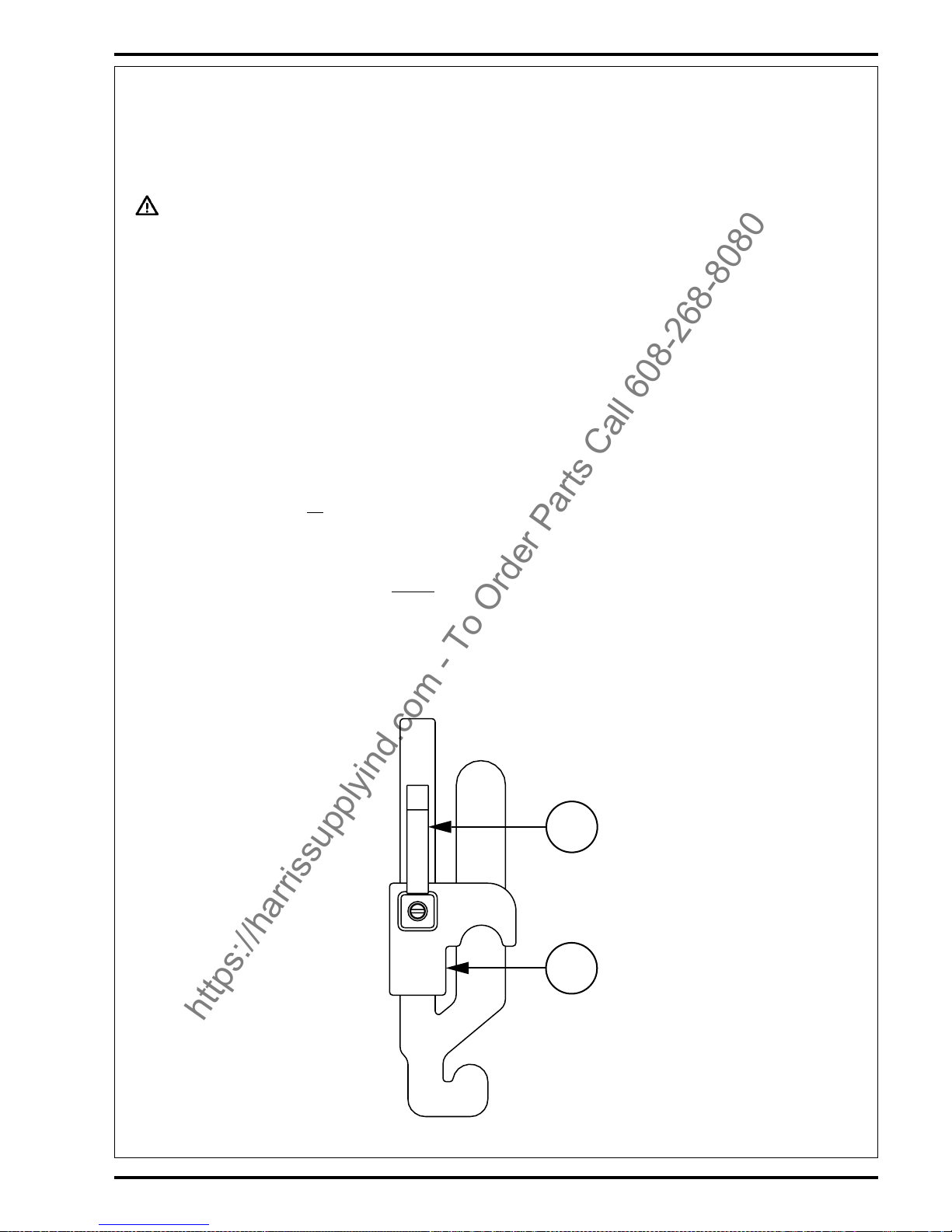
FORM NO. 56041432 / 2060 - 29
A
B
MANTENIMIENTO DEL CEPILLO PRINCIPAL
Dado que el motor del cepillo principal gira siempre en la misma dirección, las cerdas acaban por curvarse, reduciendo la eficacia del barrido. Para corregir esto
puede retirar el cepillo principal y darle la vuelta. Este procedimiento debe realizarse cada 30 horas de funcionamiento.
El cepillo principal debe cambiarse cuando las cerdas estén gastadas hasta una longitud de 6,35 cm. El tope del cepillo principal debe volver a ajustarse cuando
se cambie el cepillo principal.
NOTA: La máquina debe guardarse con el cepillo principal en posición elevada.
¡ADVERTENCIA!
El motor debe estar apagado cuando se realice este procedimiento.
Para cambiar el cepillo principal o darle la vuelta...
1 Sitúe el interruptor de llave de encendido (52) en posición OFF de apagado.
2 Sitúe la palanca de elevación / descenso (ON / OFF) del cepillo principal (53) en posición DOWN.
3 Abra la puerta de acceso al cepillo principal (15).
4 Retire el perno grande en T del lateral del brazo libre del cepillo. Gire el conjunto del brazo hasta sacarlo del núcleo del cepillo principal.
5 Saque el cepillo principal de su alojamiento y retire las cuerdas o alambres que puedan haber quedado enrollados en él. Examine también los zócalos
de la parte delantera, trasera y laterales del alojamiento del cepillo. Cambie o ajuste los zócalos si están rotos o gastados hasta una altura superior a 6,35
mm del suelo.
6 Dé la vuelta al cepillo y vuelva a colocarlo en su alojamiento. Asegúrese de que las lengüetas del cubo de transmisión del cepillo (lado izquierdo) encajen
en las ranuras del núcleo del cepillo.
7 Introduzca de nuevo el conjunto del brazo en el núcleo del cepillo e instale el perno en T que sujeta el brazo.
8 Cierre bien la puerta de acceso al cepillo principal (15).
Para ajustar la altura del cepillo principal...
1 Lleve la máquina a una zona con el suelo nivelado y eche el freno de estacionamiento.
2 Eche hacia atrás la palanca de elevación / descenso (ON/OFF) del cepillo principal (53) y deslícela hacia la izquierda y hacia arriba para bajar y poner
en marcha el cepillo principal.
NO mueva la máquina.
3 Deje en marcha el cepillo principal durante 1 minuto, barriendo una “banda” del suelo. Al cabo de 1 minuto, levante el cepillo, suelte el freno de
estacionamiento y mueva la máquina para que quede visible la banda barrida.
4 Examine la banda barrida del suelo. Si su anchura es inferior a 5,08 cm o superior a 7,62 cm, será necesario ajustar el cepillo.
5 Para ajustar el cepillo, afloje el mango (A) y deslice la abrazadera de tope (B) hacia arriba o hacia abajo para subir o bajar el cepillo principal. Cuanto
más arriba se desplace la palanca (5) en la ranura, más bajo quedará el cepillo principal. Apriete el mango (A) una vez ajustada la posición de la abrazadera
de tope (B).
6 Repita los pasos 1-5 hasta que la banda barrida presente una anchura de 5,08-7,62 cm.
La anchura de la banda barrida debe ser la misma en ambos extremos del cepillo. Si los extremos son más estrechos, lleve la máquina a una zona distinta
y repita los pasos 1-5. Si la banda barrida sigue presentando una forma desigual, póngase en contacto con su proveedor Nilfisk-Advance.
https://harrissupplyind.com - To Order Parts Call 608-268-8080
Page 29

30 - FORM NO. 56041432 / 2060
HOPPER DUST CONTROL FILTER
The hopper dust control filter must be cleaned regularly to maintain the efficiency
of the vacuum system. Follow the recommended filter service intervals for the
longest filter life.
CAUTION!
Wear safety glasses when cleaning the filter.
Do not puncture the paper filter.
Clean the filter in a well-ventilated area.
To remove the hopper dust control filter...
1 Lift the Hopper Cover (6) on top of the hopper. Make sure that the
Hopper Cover Prop Rod (7) is in place.
2 Inspect the top of the Hopper Dust Control Filter (10) for damage. A
large amount of dust on top of the filter is usually caused by a hole in the
filter or a damaged filter gasket.
3 Turn the two hold-downs to the side (one on each side at the front of the
frame) to release the shaker frame, then swing the Dust Filter Shaker
Assembly (12) up and latch in place with the Shaker Assembly Latch
(11).
4 Lift the Hopper Dust Control Filter (10) out of the machine.
5 Clean the filter using one of the methods below:
Method “A”
Vacuum loose dust from the filter. Then gently tap the filter against a
flat surface (with the dirty side down) to remove loose dust and dirt.
NOTE: Take care not to damage the metal lip which extends past the
gasket.
Method “B”
Vacuum loose dust from the filter. Then blow compressed air (maximum
pressure 100 psi) into the clean side of the filter (in the opposite direction
of the airflow).
Method “C”
Vacuum loose dust from the filter. Then soak the filter in warm water for
15 minutes, then rinse it under a gentle stream of water (maximum
pressure 40 psi). Let the filter dry completely before putting it back into
the machine.
6 Follow the instructions in reverse order to install the filter. If the gasket
on the filter is torn or missing, it must be replaced.
FILTRO DE CONTROL DE POLVO DE LA
TOLVA
El filtro de control de polvo de la tolva debe limpiarse con regularidad para
mantener la eficacia del sistema de aspiración. Respete la frecuencia de
servicio recomendada para conseguir la máxima duración del filtro.
¡PRECAUCIÓN!
Lleve puestas unas gafas protectoras para limpiar el filtro.
No perfore el filtro de papel.
Limpie el filtro en una zona bien ventilada.
Para retirar el filtro de control de polvo de la tolva...
1 Levante la cubierta de la tolva (6) situada en la parte superior de ésta.
Compruebe que la varilla de apoyo de la cubierta de la tolva (7) se
encuentra colocada en su lugar.
2 Examine la parte superior del filtro de control de polvo de la tolva (10)
para comprobar si existe algún deterioro. La acumulación de gran
cantidad de polvo en la parte superior del filtro suele deberse a la
presencia de agujeros en el filtro o a daños en la junta.
3 Retire las dos sujeciones (una a cada lado de la parte delantera de la
estructura) para dejar libre la estructura del agitador, saque el agitador
del filtro de polvo (12) y colóquelo con el pestillo del conjunto del
agitador (11).
4 Saque de la máquina el filtro de control de polvo (10).
5 Limpie el filtro de acuerdo con uno de los siguientes métodos:
Método «A»
Desprenda el polvo del filtro mediante aspiración. A continuación,
golpee suavemente el filtro contra una superficie plana (con el lado
sucio hacia abajo) para eliminar el polvo y la suciedad. NOTA: Procure
no dañar el borde metálico que se extiende más allá de la junta.
Método «B»
Desprenda el polvo del filtro mediante aspiración. A continuación,
aplique aire comprimido (presión máxima: 100 libras por pulgada
cuadrada) al lado limpio del filtro (en dirección contraria a la corriente
de aire).
Método «C»
Desprenda el polvo del filtro mediante aspiración. A continuación,
introduzca el filtro en agua templada durante 15 minutos, aclárelo con
un chorro suave de agua (presión máxima: 40 libras por pulgada
cuadrada). Deje secar completamente el filtro antes de volver a
colocarlo en la máquina.
6 Siga las instrucciones en el orden inverso para instalar el filtro. Si la
junta del filtro está rota o falta, debe instalarse una nueva.
https://harrissupplyind.com - To Order Parts Call 608-268-8080
Page 30

FORM NO. 56041432 / 2060 - 31
A
B
C
D
E
F
PARKING BRAKE LEVER ADJUSTMENT
The Parking Brake Lever (3) should be re-adjusted to where it firmly holds it’s (locked park) setting with out easily being released.
Normal adjustment of the parking brake can be accomplished from the operator compartment. Turn the handle knob on the end of the lever clockwise (CW) to
increase the brake tension. Note: If the knob adjustment is inadequate to firmly hold its brake setting, this indicates the need to inspect the brake shoes and linkage
for wear and the need for service or replacement.
ENGINE OIL
Check the engine oil level (29) before every use. The machine should be parked on a level surface and the engine cool. Change the engine oil after the first 35
hours of operation and every 150 hours after that. The oil filter should be replaced with every oil change. The type of oil used depends on the air temperature where
the machine is used.
TEMPERATURE RANGE OIL WEIGHT
above 60° F (15° C) SAE 10W-30
below 60° F (15° C) SAE 5W-30
ENGINE AIR FILTER
The Engine Air Filter (30) is located in the Circuit Breaker/Battery Compartment. Check the Air Filter Service Indicator (58) before each use of the machine. Do
not service the air filter unless the red flag is visible in the service indicator.
CAUTION!
When servicing the engine air filter elements, use extreme care to prevent loose dust from entering the engine. Dust can severely
damage the engine.
The engine air filter contains a Primary (outer) and a Safety (inner) filter element. The Primary Element may be cleaned twice before being replaced. The Safety
Element should be replaced every third time that the Primary Filter Element is replaced.
Never attempt to clean the Inner Safety Element.
To clean the Primary Filter Element, unsnap the 2 clips at the end of the air filter and remove the end housing. Pull the primary element out. Clean the element
with compressed air (maximum pressure 100 psi) or wash it with water (maximum pressure 40 psi). DO NOT put the element back into the canister until it is
completely dry.
CIRCUIT BREAKER LOCATION (G, P, DU)
A Horn C.B. (F6 / 10A)
B Head Lights / Tail Lights C.B. (F4 / 20A)
C Ignition Circuit C.B. (F2 / 15A)
D Shaker Motor C.B. (F5 / 8A)
E Accessory Circuit C.B. (F3 / 15A)
F Main C.B. (F1 / 40A)
CIRCUIT BREAKER LOCATION (D)
A Horn C.B. (F6 / 10A)
B Head Lights / Tail Lights C.B. (F4 / 20A)
C Accessory Circuit C.B. (F2 / 10A)
D Shaker Motor C.B. (F5 / 8A)
E Accessory Circuit C.B. (F3 / 15A)
F Main C.B. (F1 / 40A)
A
B
C
D
E
F
https://harrissupplyind.com - To Order Parts Call 608-268-8080
Page 31

32 - FORM NO. 56041432 / 2060
A
B
C
D
E
F
AJUSTE DE LA PALANCA DEL FRENO DE ESTACIONAMIENTO
La palanca del freno de estacionamiento (3) ha de reajustarse en su posición (de estacionamiento) sin que se suelte con facilidad.
El ajuste normal del freno de estacionamiento puede realizarse desde el compartimento del operador. Gire el mando situado en el extremo de la palanca en el
sentido de las agujas del reloj para aumentar la tensión del freno. Nota: Si el ajuste del mando es inadecuado para mantener sujeto el freno en su posición, será
necesario examinar el desgaste de las zapatas del freno y las conexiones, y revisarlas o cambiarlas.
ACEITE DEL MOTOR
Compruebe el nivel del aceite del motor (29) antes de cada utilización. La máquina debe estacionarse en una superficie nivelada, dejando enfriar el motor. Cambie
el aceite del motor al cabo de las primeras 35 horas de funcionamiento y, con posterioridad, cada 150 horas. El filtro del aceite debe cambiarse cada vez que
se cambie el aceite. El tipo de aceite utilizado depende de la temperatura del aire en el lugar de utilización de la máquina.
TEMPERATURA PESO DEL ACEITE
por encima de 15° C SAE 10W-30
por debajo de 15° C SAE 5W-30
FILTRO DEL AIRE DEL MOTOR
El filtro del aire del motor (30) está situado en el compartimento de los disyuntores/batería. Compruebe el indicador de servicio del filtro del aire (58) cada vez
antes de la utilización de la máquina. No realice operaciones de servicio en el filtro del aire si no aparece la bandera roja en el indicador de servicio.
¡PRECAUCIÓN!
Cuando realice operaciones de servicio en los elementos del filtro del aire, extreme las precauciones para impedir que el polvo suelto
penetre en el motor, ya que podría dañarlo gravemente.
El filtro del aire del motor contiene un elemento de filtro principal (externo) y un elemento de filtro de seguridad (interno). El elemento principal puede limpiarse
dos veces antes ser sustituido. El elemento de seguridad debe cambiarse una vez por cada tres veces que se cambie el elemento de filtro principal. No intente
nunca limpiar el elemento interno de seguridad.
Para limpiar el elemento de filtro principal, retire las 2 pinzas del extremo del filtro del aire y retire el alojamiento del extremo. Saque el elemento principal y límpielo
con aire comprimido (presión máxima: 100 libras por pulgada cuadrada) o lávelo con agua (presión máxima: 40 libras por pulgada cuadrada). NO vuelva a colocar
el elemento en el cartucho hasta que esté completamente seco.
UBICACIÓN DE LOS DISYUNTORES (G, P, DU)
A Disyuntor del claxon (F6 / 10A)
B Disyuntor de los faros delanteros / traseros (F4 / 20A)
C Disyuntor del circuito de encendido (F2 / 15A)
D Disyuntor del motor del agitador (F5 / 8A)
E Disyuntor del circuito accesorio (F3 / 15A)
F Disyuntor principal (F1 / 40A)
UBICACIÓN DE LOS DISYUNTORES (D)
A Disyuntor del claxon (F6 / 10A)
B Disyuntor de los faros delanteros / traseros (F4 / 20A)
C Disyuntor del circuito accesorio (F2 / 10A)
D Disyuntor del motor del agitador (F5 / 8A)
E Disyuntor del circuito accesorio (F3 / 15A)
F Disyuntor principal (F1 / 40A)
A
B
C
D
E
F
https://harrissupplyind.com - To Order Parts Call 608-268-8080
Page 32

FORM NO. 56041432 / 2060 - 33
TROUBLESHOOTING
If the possible causes listed below are not the source of trouble, it is a symptom
of something more serious. Contact your Nilfisk-Advance Service Center
immediately for service.
TRIPPING THE CIRCUIT BREAKERS
The circuit breakers are located on the Circuit Breaker Panel (33), they protect
electrical circuits and motors from damage due to overload conditions. If a circuit
breaker trips, try to determine the cause.
Shaker Motor Circuit Breaker (8 Amp) Possible causes may be:
1 Electrical short circuit (have your Nilfisk-Advance Service Center or
qualified electrician check the machine)
2 Overloaded or jammed shaker motor (check shaker motor)
Accessory Circuit 1 Circuit Breaker (15 Amp) Possible cause may be:
1 Electrical short circuit (have your Nilfisk-Advance Service Center or
qualified electrician check the machine)
Ignition Circuit Circuit Breaker (15 Amp) Possible cause may be:
1 Electrical short circuit (have your Nilfisk-Advance Service Center or
qualified electrician check the machine)
Horn Circuit Breaker (10 Amp) Possible cause may be:
1 Electrical short circuit (have your Nilfisk-Advance Service Center or
qualified electrician check the machine)
Headlight / Tail Light Circuit Breaker (20 Amp) Possible cause may be:
1 Electrical short circuit (have your Nilfisk-Advance Service Center or
qualified electrician check the machine)
Main Circuit Breaker (40 Amp) Possible cause may be:
1 Electrical short circuit (have your Nilfisk-Advance Service Center or
qualified electrician check the machine)
Once the problem has been corrected, push the button in to reset the circuit
breaker. If the button does not stay in, wait 5 minutes and try again. If the circuit
breaker trips repeatedly, call your Nilfisk-Advance Service Center for service.
LOCALIZACIÓN DE AVERÍAS
Si las posibles causas indicadas a continuación no son el origen del problema,
éste es un síntoma de algo más grave. Póngase en contacto inmediatamente
con su Centro de Servicio Nilfisk-Advance.
DESCONEXIÓN DE LOS DISYUNTORES
Los disyuntores están situados en el panel de disyuntores (33) y protegen los
circuitos eléctricos y los motores de los daños provocados por condiciones de
sobrecarga. Si se produce la desconexión de algún disyuntor, intente averiguar
la causa.
Posibles causas de desconexión del disyuntor del motor del agitador (8 A):
1 Cortocircuito eléctrico (revise la máquina en un Centro de Servicio
Nilfisk-Advance o consulte a un electricista cualificado)
2 Sobrecarga o atascamiento del motor del agitador (revise el motor del
agitador)
Posibles causas de desconexión del disyuntor del circuito accesorio (15 A):
1 Cortocircuito eléctrico (revise la máquina en un Centro de Servicio
Nilfisk-Advance o consulte a un electricista cualificado)
Posibles causas de desconexión del disyuntor del circuito de encendido (15 A):
1 Cortocircuito eléctrico (revise la máquina en un Centro de Servicio
Nilfisk-Advance o consulte a un electricista cualificado)
Posibles causas de desconexión del disyuntor del claxon (10 A):
1 Cortocircuito eléctrico (revise la máquina en un Centro de Servicio
Nilfisk-Advance o consulte a un electricista cualificado)
Posibles causas de desconexión del disyuntor de los faros delanteros / traseros
(20 A):
1 Cortocircuito eléctrico (revise la máquina en un Centro de Servicio
Nilfisk-Advance o consulte a un electricista cualificado)
Posibles causas de desconexión del disyuntor principal (40 A):
1 Cortocircuito eléctrico (revise la máquina en un Centro de Servicio
Nilfisk-Advance o consulte a un electricista cualificado)
Una vez corregido el problema, pulse el botón para volver a conectar el
disyuntor. Si el botón no queda pulsado, espere 5 minutos e inténtelo de nuevo.
Si el disyuntor se desconecta una y otra vez, póngase en contacto con su Centro
de Servicio Nilfisk-Advance.
https://harrissupplyind.com - To Order Parts Call 608-268-8080
Page 33

34 - FORM NO. 56041432 / 2060
TROUBLESHOOTING
If the possible causes listed below are not the source of trouble, it is a symptom
of something more serious. Contact your Nilfisk-Advance Service Center
immediately for service.
MACHINE WILL NOT MOVE
Possible causes may be:
1 Parking Brake (3) set (release parking brake)
2 Towing Valve in wrong position (set correctly)
3 Tripped circuit breaker(s) (reset any tripped circuit breakers)
MAIN BROOM WILL NOT RUN
Possible causes may be:
1 Hopper door is not open (open hopper door)
2 Debris wrapped around the broom drive (remove debris)
3 Hopper is not completely down (lower hopper completely)
4 Tripped circuit breaker(s) (reset any tripped circuit breakers)
SIDE BROOM WILL NOT RUN
Possible causes may be:
1 Hopper door is not open (open hopper door)
2 Debris wrapped around the broom drive (remove debris)
3 Hopper is not completely down (lower hopper completely)
4 Tripped circuit breaker(s) (reset any tripped circuit breakers)
HOPPER WILL NOT RAISE
Possible causes may be:
1 Tripped circuit breaker(s) (reset any tripped circuit breakers)
HOPPER DUMP DOOR WILL NOT OPEN
Possible causes may be:
1 Dump door jammed by debris (remove debris and clean edges of dirt
chamber)
2 Tripped circuit breaker(s) (reset any tripped circuit breakers)
SHAKER MOTOR WILL NOT RUN
Possible causes may be:
1 Tripped circuit breaker(s) (reset any tripped circuit breakers)
DUST CONTROL SYSTEM (IMPELLER) WILL
NOT RUN
Possible causes may be:
1 Tripped circuit breaker(s) (reset any tripped circuit breakers)
LOCALIZACIÓN DE AVERÍAS
Si las posibles causas indicadas a continuación no son el origen del problema,
éste es un síntoma de algo más grave. Póngase en contacto inmediatamente
con su Centro de Servicio Nilfisk-Advance.
LA MÁQUINA NO SE MUEVE
Posibles causas:
1 Freno de estacionamiento (3) echado (suelte el freno de
estacionamiento)
2 Válvula de remolque en posición incorrecta (colóquela en posición
correcta)
3 Desconexión de algún disyuntor (conecte de nuevo los disyuntores
desconectados)
EL CEPILLO PRINCIPAL NO FUNCIONA
Posibles causas:
1 La puerta de la tolva no está abierta (abra la puerta de la tolva)
2 Residuos atascados en la transmisión del cepillo (retire los residuos)
3 La tolva no está bajada del todo (baje del todo la tolva)
4 Desconexión de algún disyuntor (conecte de nuevo los disyuntores
desconectados)
EL CEPILLO LATERAL NO FUNCIONA
Posibles causas:
1 La puerta de la tolva no está abierta (abra la puerta de la tolva)
2 Residuos atascados en la transmisión del cepillo (retire los residuos)
3 La tolva no está bajada del todo (baje del todo la tolva)
4 Desconexión de algún disyuntor (conecte de nuevo los disyuntores
desconectados)
LA TOLVA NO SE ELEVA
Posibles causas:
1 Desconexión de algún disyuntor (conecte de nuevo los disyuntores
desconectados)
LA PUERTA DE DESCARGA DE LA TOLVA NO
SE ABRE
Posibles causas:
1 Atascamiento de la puerta de descarga por la presencia de residuos
(retire los residuos y limpie los bordes de la cámara sucia)
2 Desconexión de algún disyuntor (conecte de nuevo los disyuntores
desconectados)
EL MOTOR DEL AGITADOR NO FUNCIONA
Posibles causas:
1 Desconexión de algún disyuntor (conecte de nuevo los disyuntores
desconectados)
EL SISTEMA DE CONTROL DE POLVO
(PROPULSOR) NO FUNCIONA
Posibles causas:
1 Desconexión de algún disyuntor (conecte de nuevo los disyuntores
desconectados)
https://harrissupplyind.com - To Order Parts Call 608-268-8080
Page 34

FORM NO. 56041432 / 2060 - 35
TECHNICAL SPECIFICATIONS (as installed and tested on the unit)
Model 2060DU 2060G 2060P 2060D
Model No. 56418002 56418001 56418000 56418003
Sound Power Level (ISO 3744) dB(A)/20µPa 85 85 85 85
Total Weight lbs/kg 4,201 / 1,905 4,201 / 1,905 4,201 / 1,905 4,201 / 1,905
Vibrations at the Hand Controls m/s
2
<2.5 m/s
2
<2.5 m/s
2
<2.5 m/s
2
<2.5 m/s
2
Vibrations at the Seat m/s
2
<0.5 m/s
2
<0.5 m/s
2
<0.5 m/s
2
<0.5 m/s
2
Gradeability 26.8% (150) 26.8% (150) 26.8% (150) 26.8% (150)
ESPECIFICACIONES TÉCNICAS (según la instalación y comprobaciones de la unidad)
Modelo 2060DU 2060G 2060P 2060D
Nº Modelo 56418002 56418001 56418000 56418003
Nivel de ruido (ISO 3744) dB(A)/20µPa 85 85 85 85
Peso total kg 4,201 / 1,905 4,201 / 1,905 4,201 / 1,905 4,201 / 1,905
Vibración en los controles manuales m/s
2
<2,5 m/s
2
<2,5 m/s
2
<2,5 m/s
2
<2,5 m/s
2
Vibración en el asiento m/s
2
<0,5 m/s
2
<0,5 m/s
2
<0,5 m/s
2
<0,5 m/s
2
Capacidad ascendente 26,8% (150) 26,8% (150) 26,8% (150) 26,8% (150)
revised 5/00
https://harrissupplyind.com - To Order Parts Call 608-268-8080
Page 35

Nilfisk-Advance, Inc.
14600 21st Avenue North
Plymouth, M N, 55447-3408
www.nilfisk -advance.com
Phone: 800-989-2235
Fax: 800-989-6566
©2000 Nilfisk-Advance, Inc.,
Plymouth, M N 5 5447-3408
Printed in the U.S.A.
https://harrissupplyind.com - To Order Parts Call 608-268-8080
 Loading...