

Nilfisk-Advance FM810 ST 56105614, FM810 XP 56105616, FM810 ST, FM810 XP, 56105614 Instruction Manual
...Page 1

FM810 ST, FM810 XP
https://harrissupplyind.com - To Order Parts Call 608-268-8080
Instructions For Use - Original Instructions
Instrucciones de uso
Mode d’ emploi
Models: 56105614 (ST), 56105616 (XP)
A-English
B-Español
C-Français
2/2015 FORM NO. 56091150 REV A
Page 2

https://harrissupplyind.com - To Order Parts Call 608-268-8080
Page 3

INSTRUCTIONS FOR USEA - ENGLISH
https://harrissupplyind.com - To Order Parts Call 608-268-8080
TABLE OF CONTENTS
Page
Introduction .........................................................................................A-2
Parts and Service ...............................................................................A-2
Nameplate ..........................................................................................A-2
Unpacking the Machine ......................................................................A-2
Cautions and Warnings ......................................................................A-3
Grounding Instructions .......................................................................A-4
Know Y our Machine ............................................................................A-5
Transporting the Machine ...................................................................A-6
Machine Setup ....................................................................................A-7
Operating the Machine
Operating Instructions – Floor Finish Recoat Prep .............................A-8
Operating Instructions - Scrubbing .....................................................A-9
Troubleshooting ................................................................................A-10
Technical Specifi cations ...................................................................A-10
INTRODUCTION
This manual will help you get the most from your Advance fl oor machine. Read it thoroughly before operating the machine.
Note: Bold numbers in parentheses indicate an item illustrated on page A-5 unless otherwise noted.
This product is intended for commercial use only.
P ARTS AND SERVICE
Repairs, when required, should be performed by your Authorized Advance Service Center, who employs factory trained service personnel, and maintains an
inventory of Advance original replacement parts and accessories.
Call Advance for repair parts or service. Please specify the Model and Serial Number when discussing your machine.
If your dealer is unable to assist you, please call Advance at 800-989-2235
.
MODIFICATIONS
Modifi cations and additions to the cleaning machine which affect capacity and safe operation shall not be performed by the customer or user without prior written
approval from Nilfi sk-Advance Inc. Unapproved modifi cations will void the machine warranty and make the customer liable for any resulting accidents.
NAMEPLATE
The Model and Serial Number of your machine are shown on the Nameplate in the battery compartment. This information is needed when ordering repair parts
for the machine. Use the space below to note the Model and Serial Number of your machine for future reference.
Model ______________________________________________
Serial Number ________________________________________
UNPACKING THE MACHINE
When the machine is delivered, carefully inspect the shipping packaging and the machine for damage. If damage is evident, save the shipping carton (if
applicable) so that it can be inspected. Contact the Advance Customer Service Department immediately to fi le a freight damage claim.
WARNING!
The Products sold with this Manual contain or may contain chemicals that are known to certain governments (such as the State of California, as
identifi ed in its Proposition 65 Regulatory Warning Law) to cause cancer, birth defects or other reproductive harm. In certain locations (including
the State of California) purchasers of these Products that place them in service at an employment job site or a publicly accessible space are
required by regulation to make certain notices, warnings or disclosures regarding the chemicals that are or may be contained in the Products at or
about such work sites. It is the purchaser’s responsibility to know the content of, and to comply with, any laws and regulations relating to the use
of these Products in such environments. The Manufacturer disclaims any responsibility to advise purchasers of any specifi c requirements that
may be applicable to the use of the Products in such environments.
A-2 FM810 ST, FM810 XP - 56091150 2/2015
Page 4

ENGLISH - AINSTRUCTIONS FOR USE
https://harrissupplyind.com - To Order Parts Call 608-268-8080
CAUTIONS AND WARNINGS
SYMBOLS
Advance uses the symbols below to signal potentially dangerous conditions. Read this information carefully and take the necessary
steps to protect personnel and property.
DANGER!
Is used to warn of immediate hazards that will cause severe personal injury or death.
WARNING!
Is used to call attention to a situation that could cause severe personal injury.
CAUTION!
Is used to call attention to a situation that could cause minor personal injury or damage to the machine or other property.
Read all instructions before using.
GENERAL SAFETY INSTRUCTIONS
Specifi c Cautions and Warnings are included to warn you of potential danger of machine damage or bodily harm.
DANGER!
* Failure to read the Owner’s Manual prior to operating or servicing your Advance machine could result in injury to you or to other personnel;
damage to the machine or to other property could occur as well. You must have training in the operation of this machine before using it. If
you or your operator(s) cannot read English, have this manual explained fully before attempting to operate this machine.
* Sanding/fi nishing wood fl oors can create an explosive or combustible environment. Do not operate this machine around solvents, thinners,
alcohol, fuels, fl oor fi nishes, wood dust or any other fl ammable materials. Cigarette lighters, pilot lights, electrical sparks and all other
sources of ignition should be extinguished or avoided. Keep work area well ventilated.
* Dust generated from sanding wood fl oors can spontaneously ignite or explode. Promptly dispose of any sanding dust in a metal container
clear of any combustibles. Do not dispose in a fi re.
* Electrocution could occur if the machine is being serviced while the machine is connected to a power source. Disconnect the power supply
before servicing.
* Electrocution or fi re could occur if the machine is being operated with a damaged power cord. Keep the power cord clear of the pad. Always
lift the cord over the machine. Do not move the machine by the power cord.
* Shock hazard. Do not use the machine if it has been rained on or sprayed with water.
* To avoid injury keep hands, feet, and loose clothing away from all moving parts on the machine. Disconnect the power cord before replacing
the pad, changing the abrasive, or when servicing. Do not operate the machine unless all guards are in place. Never leave the machine
unattended while connected to a power source.
WARNING!
* Injury can occur if protective clothing or equipment is not used while sanding. Always wear safety goggles, protective clothing, and dust mask
while sanding.
* This sander is not to be used on pressure treated wood. Some pressure treated woods contain arsenic and sanding pressure treated wood
produces hazardous dust. Inhaling hazardous dust from pressure treated wood can cause serious injury or death. Sanding pressure treated
wood decks or uneven surfaces can damage the sander which is not covered under warranty or damage waiver.
* Any alterations or modifi cations of this machine could result in damage to the machine or injury to the operator or other bystanders.
Alterations or modifi cations not authorized by the manufacturer voids any and all warranties and liabilities.
2/2015 A-3 56091150 - FM810 ST, FM810 XP
SAVE THESE INSTRUCTIONS
Page 5

INSTRUCTIONS FOR USEA - ENGLISH
https://harrissupplyind.com - To Order Parts Call 608-268-8080
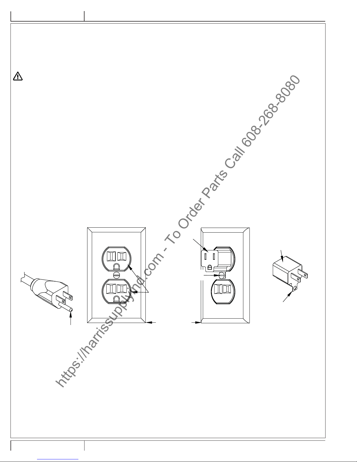
120VAC GROUNDING INSTRUCTIONS
This appliance must be grounded. If it should electrically malfunction, grounding provides a path of least resistance for electric current to reduce
the risk of electric shock. This appliance is equipped with a cord having an equipment-grounding conductor and grounding plug. The plug must be
plugged into an appropriate outlet that is properly installed and grounded in accordance with all local codes and ordinances.
DANGER!
Improper connection of the equipment-grounding conductor can result in a risk of electric shock. Check with a qualifi ed electrician or
service person if you are in doubt as to whether the outlet is properly grounded. Do not modify the plug provided with the appliance.
If it will not fi t the outlet, have a proper outlet installed by a qualifi ed electrician.
This appliance is for use on a nominal 120-volt circuit, and has a grounding plug that looks like the plug illustrated in Figure 1 below. A temporary
adapter illustrated in Figures 2 and 3 may be used to connect this plug to a 2-pole receptacle as shown in Figure 2 if a properly grounded outlet is
not available. The temporary adapter should be used only until a properly grounded outlet (Figure 1) can be installed by a qualifi ed electrician. The
green-colored rigid ear, tab, or the like extending from the adapter must be connected to a permanent ground such as a properly grounded outlet
box cover. Whenever the adapter is used, it must be held in place by a metal screw. Grounding adapters are not approved for use in Canada.
Replace the plug if the grounding pin is damaged or broken.
The Green (or Green/Yellow) wire in the cord is the grounding wire. When replacing a plug, this wire must be attached to the grounding pin only.
Extension cords connected to this machine should be 12 gauge minimum wire size, three-wire cords with three-prong plugs and outlets. DO NOT
use extension cords more than 50 feet (15 m) long.
PLEASE NOTE: FOR NORTH AMERICA ONLY
Grounding Pin
FIGURE 1
Adapter
Metal Screw
Grounded Outlet
Grounded Outlet Box
FIGURE 2
Adapter
Tab for Grounding Screw
FIGURE 3
A-4 FM810 ST, FM810 XP - 56091150 2/2015
Page 6

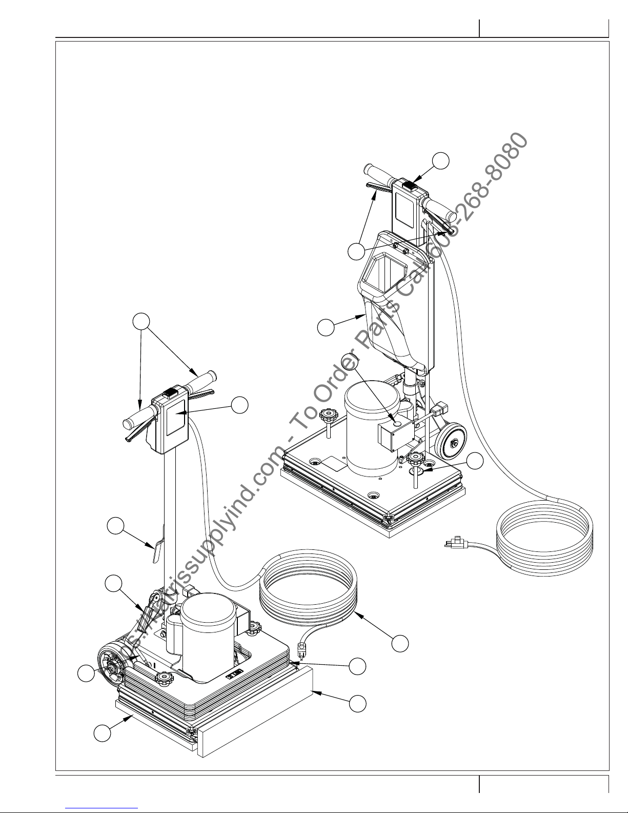
KNOW YOUR MACHINE
https://harrissupplyind.com - To Order Parts Call 608-268-8080
1 Operator Handle Grips
2 Switch Lever Safety Lock Button
3 Switch Levers - Squeeze - ON / Release - OFF
4 Handle Release Compression Lever
5 Power Cord
6 Operator Handle
7 Cord Hook
8 Wheel Raise Lock Lever (XP only)
9 Optional Solution Tank Connection
10 Pad
11 Baseboard Kit (Std. on XP, optional on ST)
12 Weights
13 Optional Solution Tank
14 Thermal Breaker
ENGLISH - AINSTRUCTIONS FOR USE
2
3
1
13
14
6
9
7
4
8
10
2/2015 A-5 56091150 - FM810 ST, FM810 XP
5
12
11
Page 7

INSTRUCTIONS FOR USEA - ENGLISH
https://harrissupplyind.com - To Order Parts Call 608-268-8080
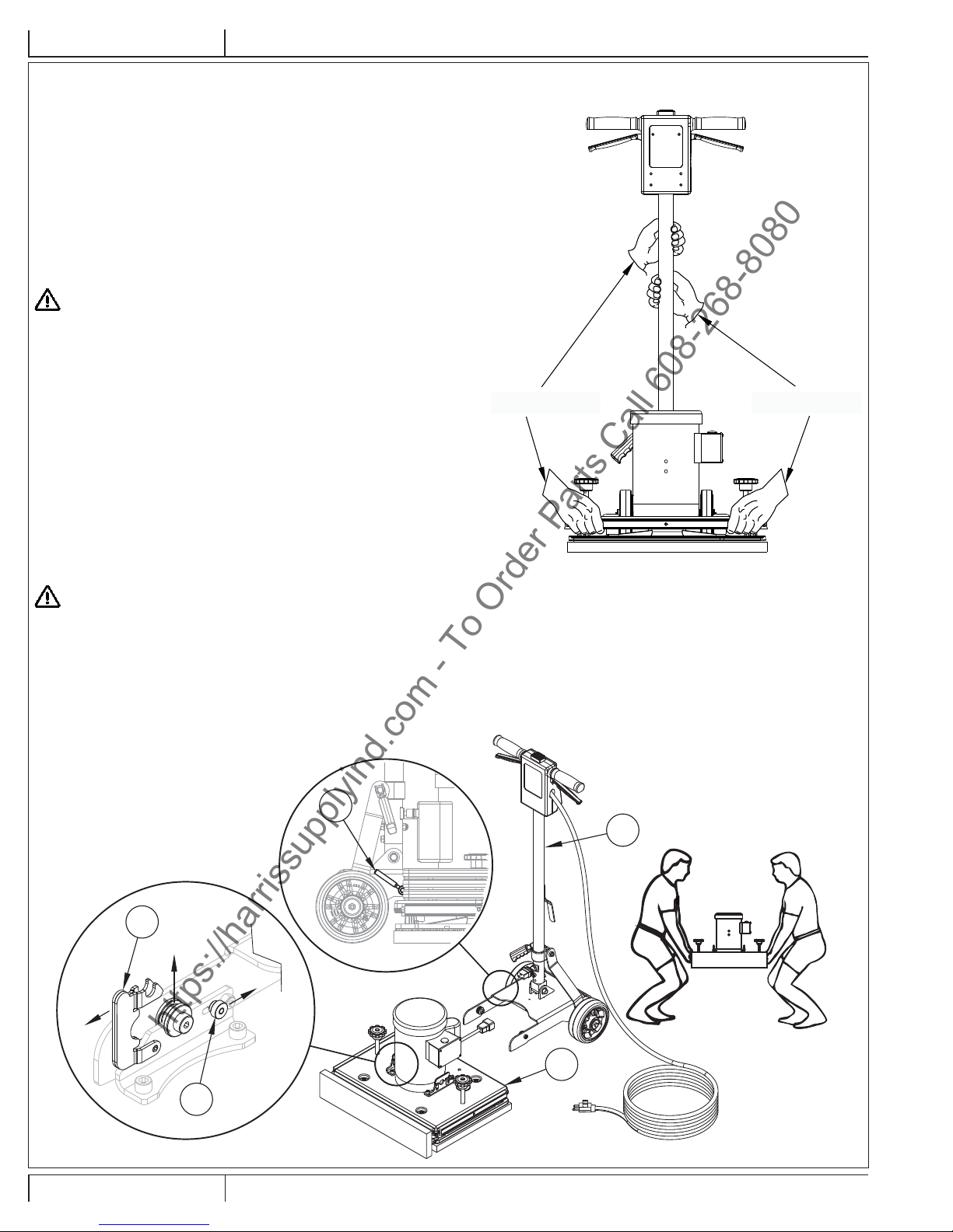
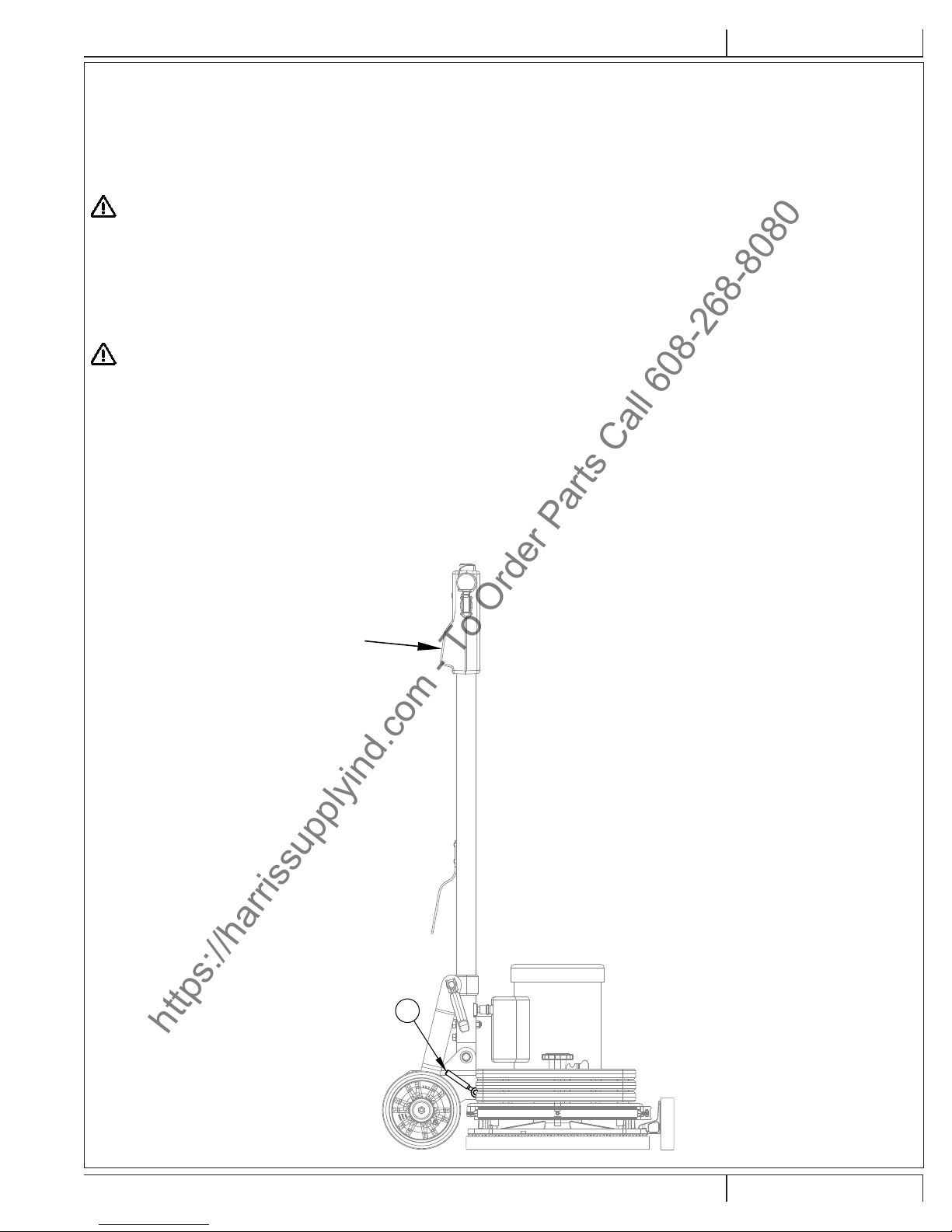
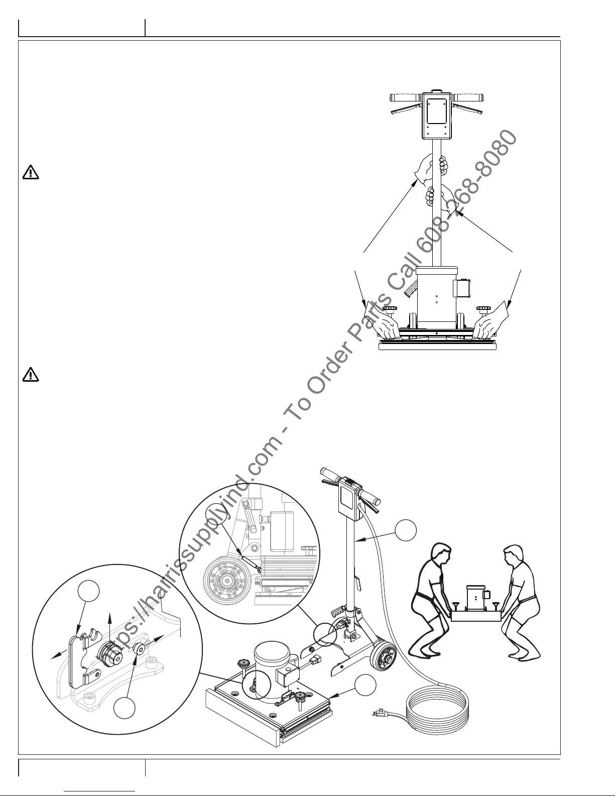
TRANSPORTING THE MACHINE
To transport the machine, follow this procedure:
1 Unplug the machine from the wall outlet and wrap the Power Cord (5)
around the Cord Hook (7) and the Operator Handle Grips (1).
2 Raise and lock the handle in the upright position. To lock the handle,
push down on the Handle Release Compression Lever (4).
3 Remove all three weights (12) and place in cargo area.
FM810 ST
4 Pick the machine up by grabbing the handle tube and the base and place
in cargo area.
WARNING!
The machine is heavy (97.5 lbs./44.2 kg). To avoid injury or damage to the
machine use a fi rm grip and proper lifting technique. Use two people, one
person on each side of the machine as shown in Figure 1.
5 Secure machine to prevent movement in cargo area.
FM810 XP
4 Remove the handle assembly from the base as shown in Figure 2.
A. Unplug the motor from the handle.
B. With the Wheel Lock Lever (8) in the up position (wheels down
position), Slide Knob (A) back and fl ip Latch (B) up as shown.
NOTE: There are two of these latches, one on each side of the
motor.
C. Tilt the Handle Assembly (C) back slightly and roll it away from the
Base Assembly (D).
5 Pick the base assembly up and place in cargo area.
PERSON #2
FIGURE 1
PERSON #1
WARNING!
The base is heavy (about 78 lbs./35.4 kg). To avoid injury or damage to the
machine use a fi rm grip and proper lifting technique. Use two people, one
person on each side of the base as shown in Figure 2.
6 Carefully lift the handle assembly up and place in cargo area.
7 Secure machine to prevent movement in cargo area.
FIGURE 2
8
B
C
D
A
A-6 FM810 ST, FM810 XP - 56091150 2/2015
Page 8

ENGLISH - AINSTRUCTIONS FOR USE
https://harrissupplyind.com - To Order Parts Call 608-268-8080
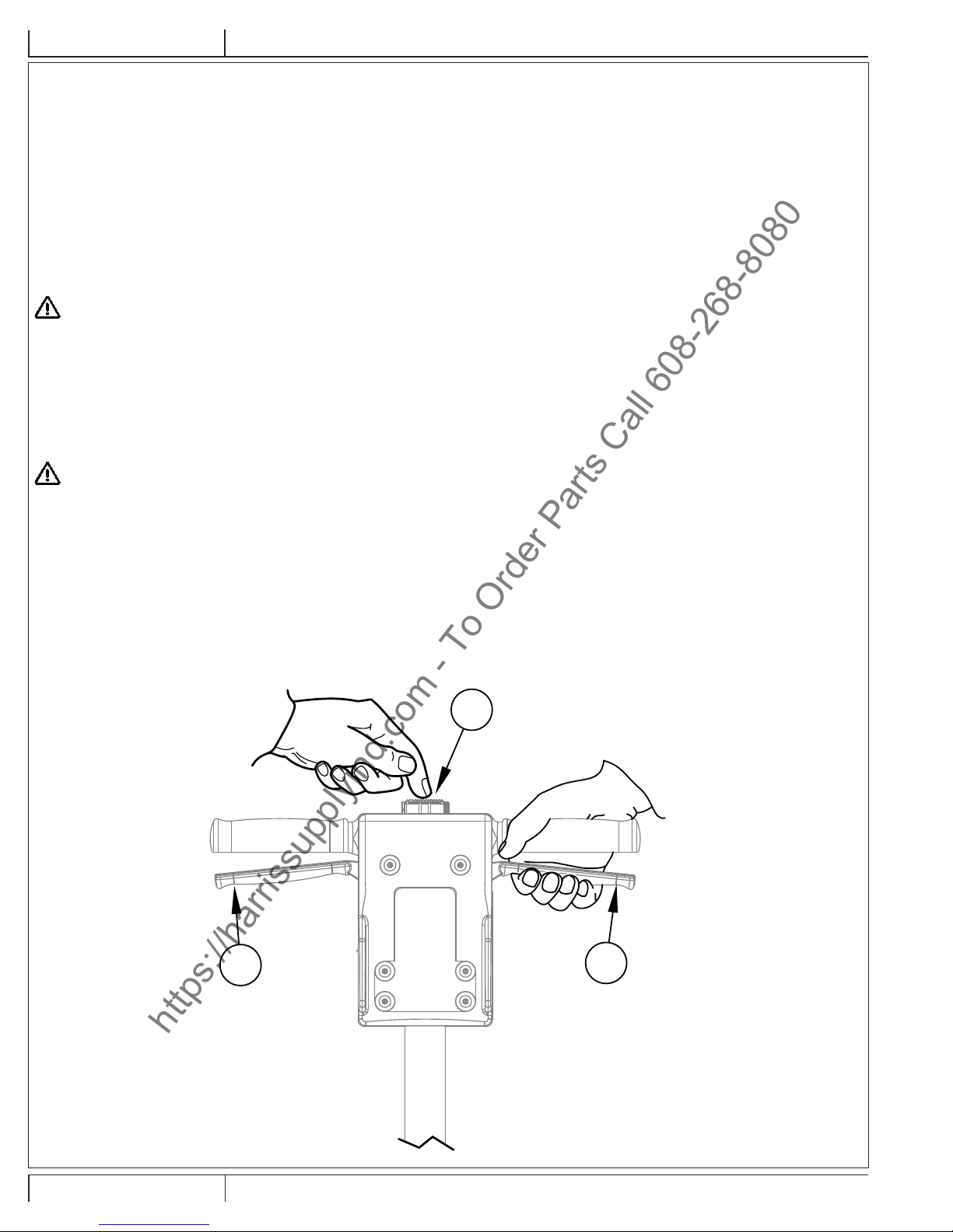
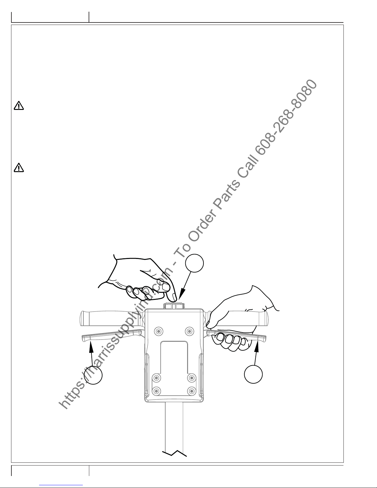
MACHINE SETUP
To prepare the machine for use follow this procedure:
1 Familiarize yourself with the machine. Read all danger, warning, and caution statements and the Operation and Parts Manual before
operating the machine.
2 Install or replace the Pad (10). The pad should be replaced if it has become matted down to a thickness of 3/8” (9.5mm) or less. To install or
replace the pad, follow these instructions:
a.) Lock the Operator Handle (6) in the upright position.
b.) Tilt the machine back until it fully rests on the Handle (6).
c.) Standing over the machine, remove existing pad then center new pad over grip face.
d.) Press Pad (10) against grip face until the hooks in the driver have set in the pad. See Figure 3.
e.) Return machine to the upright position.
CAUTION!
Damage to the grip face will occur if the machine is operated without a pad or with a pad that is 3/8” (9.5 mm) or thinner.
WARNING!
Never put yourself or let others be in a position to get injured if the machine should tip or fall, while replacing the pad or changing abrasive. Injury
can occur if the machine is connected to a power source while installing the pad or abrasive. Disconnect the machine before installing the pad or
abrasive.
FIGURE 3
10
2/2015 A-7 56091150 - FM810 ST, FM810 XP
Page 9

INSTRUCTIONS FOR USEA - ENGLISH
https://harrissupplyind.com - To Order Parts Call 608-268-8080
OPERATING INSTRUCTIONS – FLOOR FINISH RECOAT PREP
To operate the machine with an abrasive, follow this procedure:
1 Move machine to work location. Decide the best approach to abrading the desired area. When operating the machine, work so that you are
moving away from the power supply. This will help to avoid entanglement with the power cord and reduce the need to move the power cord
as frequently.
2 Install the abrasive. Use the same procedure outlined in MACHINE SETUP for installing the pad. To install the abrasive, peel the fi lm off the
back of the abrasive; center the abrasive over the pad and press it against the pad. The adhesive on the abrasive will hold it to the pad.
NOTE: When using screen or pad abrasive, set the screen on the fl oor then move the machine over the screen. Lower the machine until the
pad comes to rest on the screen. Make sure the screen is centered on the pad.
WARNING!
Injury can occur if the machine is connected to a power source while installing the pad or abrasive. Disconnect the machine before installing the
pad or abrasive.
3 Connect the machine to an appropriately fused and grounded circuit.
4 Machine may be operated with the handle in the vertical position or lowered. Release the handle by pulling up on the Handle Release
Compression Lever (4). Bring the handle to a comfortable position, and lock the handle.
5 See Figure 4. Push the Switch Lever Safety Lock Button (2), and apply pressure to the Switch Levers (3). To stop the machine, release the
Switch Levers (3).
CAUTION!
To prevent damage to the fl ooring and to reduce swirling, keep the machine in motion while the motor is running.
FM810 XP – SWITCH BETWEEN WHEELS-UP AND WHEELS-DOWN OPERATION
This model may be operated with the rear wheels up so that the pad deck is fl oating. Or it may be operated with the wheels down and in contact
with the fl oor. In the down position, the machine moves forward and backward much like a lawn mower and is more controllable and less
fatiguing. To switch between wheels up or wheels down position, activate the Lever (8) as shown in Figure 5 while applying pressure on the
handle to lift the wheels.
3
FIGURE 4
2
3
A-8 FM810 ST, FM810 XP - 56091150 2/2015
Page 10

ENGLISH - AINSTRUCTIONS FOR USE
https://harrissupplyind.com - To Order Parts Call 608-268-8080
OPERATING INSTRUCTIONS - SCRUBBING
To operate the machine as a scrubber, follow this procedure:
1 Move machine to work location. Decide the best approach to scrubbing the desired area. When scrubbing the area, work so that you are
moving away from the power supply. This will help to avoid entanglement with the power cord and reduce the need to move the power cord
as frequently.
2 Follow the procedure outlined in MACHINE SETUP for installing the pad.
WARNING!
Injury can occur if the machine is connected to a power source while installing the pad. Disconnect the machine before installing the pad.
3 Connect the machine to an appropriately fused and grounded circuit.
4 Release the handle by pulling up on the Handle Release Compression Lever (4). Bring the handle to a comfortable position, and lock the
handle.
5 See Figure 4. Push the Switch Lever Safety Lock Button (2), and apply pressure to the Switch Levers (3). To stop the machine, release the
Switch Levers (3).
CAUTION!
To prevent damage to the fl ooring and to reduce swirling, keep the machine in motion while the motor is running.
FM810 XP – SWITCH BETWEEN WHEELS-UP AND WHEELS-DOWN OPERATION
This model may be operated with the rear wheels up so that the pad deck is fl oating. Or it may be operated with the wheels down and in contact
with the fl oor. In the down position, the machine moves forward and backward much like a lawn mower and is more controllable and less
fatiguing. To switch between wheels up or wheels down position, activate the Lever (8) as shown in Figure 5 while applying pressure on the
handle to lift the wheels.
FIGURE 5
Apply Forward Pressure
When Engaging Switch (8)
8
2/2015 A-9 56091150 - FM810 ST, FM810 XP
Page 11

INSTRUCTIONS FOR USEA - ENGLISH
https://harrissupplyind.com - To Order Parts Call 608-268-8080
TROUBLESHOOTING
Problem Cause Action
Motor will not start. No power.
Check power supply and connection
Switch Lever Safety Lock Button (2) not
depressed
Defective switch / Faulty connection
Motor fails to start / runs sluggish. Low voltage from excessive length or
undersized extension cord.
Defective start capacitor.
Defective start switch.
Defective start/run capacitor
Defective motor low voltage
Fuse / Circuit Breaker repeatedly trips. Low voltage.
Bad connection.
Defective motor.
Depress Switch Lever Safety Lock Button (2)
before activating Switch Levers (3).
Contact an authorized Advance Dealer.
Use a 12 Ga extension cord, not to exceed
50’ length.
Contact an authorized Advance Dealer.
Contact an authorized Advance Dealer.
Contact an authorized Advance Dealer.
Contact an authorized Advance Dealer.
Eliminate extension cord. Locate power
source closer to work site. Have voltage
checked by a qualifi ed electrician.
Contact an authorized Advance Dealer.
Contact an authorized Advance Dealer.
TECHNICAL SPECIFICATIONS (as installed and tested on the unit)
Model FM810 ST FM810 XP
Model Number 56105614 56105616
Electrical 1.5HP - 115V/60Hz 1.5HP - 115V/60Hz
Pad/Brush Speed 3540 rpm 3540 rpm
Pad/Brush Size 14” x 20” (355mm x 508mm) 14” x 20” (355mm x 508mm)
Total Weight (w/cord) 160.5 lbs. (72.8 kg) 171 lbs. (77.5 kg)
Sound Pressure Level (ISO 11201) 69dBA 69dBA
Protection Grade IPX0 IPX0
Protection Class
Material Composition and Recyclability
Type % of machine weight % recyclable
Aluminum 1% 100%
Electrical / motors / engines - misc 38% 70%
Ferrous metals 52% 100%
Harnesses / cables 6% 67%
Liquids 0% 0%
Plastic - non-recyclable 2% 0%
Plastic - recyclable 1% 100%
Polyethylene 0% 0%
Rubber 1% 100%
A-10 FM810 ST, FM810 XP - 56091150 2/2015
Page 12

https://harrissupplyind.com - To Order Parts Call 608-268-8080
Page 13

INSTRUCCIONES DE USOB - ESPAÑOL
https://harrissupplyind.com - To Order Parts Call 608-268-8080
ÍNDICE
Página
Introducción ........................................................................................A-2
Componentes y Servicio .....................................................................A-2
Placa de identifi cación ........................................................................A-2
Desembalaje de la máquina ...............................................................A-2
Precauciones y advertencias ..............................................................A-3
Instrucciones de conexión a tierra ......................................................A-4
Conozca su máquina ..........................................................................A-5
Transporte de la máquina ...................................................................A-6
Instalación de la máquina ...................................................................A-7
Manejo de la máquina
Instrucciones de funcionamiento – Preparación
para el recubrimiento de acabado para pisos ....................................A-8
Instrucciones de funcionamiento - Fregado .......................................A-9
Resolución de problemas .................................................................A-10
Especifi caciones técnicas .................................................................A-10
INTRODUCCIÓN
Este manual lo ayudará a aprovechar al máximo su máquina para pisos Advance. Léalo con atención antes de utilizar la máquina.
Nota: Los números que aparecen en negrita entre paréntesis indican elementos ilustrados en la página A-5, a menos que se indique lo contrario.
Este producto está destinado exclusivamente a uso comercial.
COMPONENTES Y SERVICIO
Las reparaciones, cuando sean necesarias, deben ser realizadas por su Centro Autorizado de Servicio Advance, que utiliza personal de servicio formado en
fábrica y lleva un inventario de las piezas de repuesto y accesorios Advance originales.
Llame a Advance para lo referente a piezas de repuesto o servicio. Por favor, especifi que el modelo y el número de serie cuando hable de su máquina.
Si su distribuidor no puede ayudarlo, por favor llame a Advance al 800-989-2235.
MODIFICACIONES
Las modifi caciones y los agregados a la máquina de limpieza que afecten su capacidad y su funcionamiento seguro no serán realizados por el cliente o el usuario
sin la autorización previa y por escrito de Nilfi sk-Advance Inc. Las modifi caciones que no cuenten con la aprobación correspondiente anularán la garantía de la
máquina y harán que el cliente sea responsable de cualquier accidente resultante.
PLACA DE IDENTIFICACIÓN
El Número de Modelo y de Serie de la máquina se indican en la placa de identifi cación instalada en el compartimento de las baterías. Esta información es
necesaria a la hora de solicitar repuestos para la máquina. Utilice el siguiente espacio para anotar el Modelo y el Número de Serie de su máquina para futuras
consultas.
Modelo _____________________________________________
Número de serie ______________________________________
DESEMBALAJE DE LA MÁQUINA
Cuando reciba la máquina, examine con atención la caja del embalaje y la máquina, con el fi n de comprobar si existe algún daño. Si observa algún daño, guarde
la caja de embalaje (si procede) para que se pueda inspeccionar. Póngase en contacto inmediatamente con el Departamento de Servicio al Cliente de Advance
para presentar una reclamación por daños en transporte.
¡ADVERTENCIA!
Los Productos a la venta en este Manual contienen, o pueden contener, productos químicos reconocidos por algunos gobiernos (como el Estado
de California, según lo indica en su Proposición 65, Ley de Advertencia Regulatoria) como causantes de cáncer, defectos de nacimiento u
otros daños reproductivos. En algunas jurisdicciones (incluido el Estado de California), los compradores de estos Productos que los coloquen
en servicio en un emplazamiento laboral o en un espacio de acceso público tienen la obligación regulatoria de realizar determinados avisos,
advertencias o divulgaciones respecto de los productos químicos contenidos o posiblemente contenidos en los Productos utilizados en tal lugar.
Es la responsabilidad del comprador conocer y cumplir con todas las leyes y reglamentaciones relacionadas con el uso de estos Productos en
tales entornos. El Fabricante niega toda responsabilidad de informar a los compradores sobre requisitos específi cos que pueden regir el uso de
los Productos en tales entornos.
B-2 FM810 ST, FM810 XP - 56091150 2/2015
Page 14

ESPAÑOL - BINSTRUCCIONES DE USO
https://harrissupplyind.com - To Order Parts Call 608-268-8080
PRECAUCIONES Y ADVERTENCIAS
SÍMBOLOS
Advance utiliza los símbolos que se indican más abajo para señalar situaciones potencialmente peligrosas. Lea cuidadosamente
esta información y emprenda las acciones que resulten necesarias para proteger a personas y objetos.
¡PELIGRO!
Se utiliza para advertir de riesgos inmediatos que producirán lesiones personales graves o incluso fatales.
¡ADVERTENCIA!
Se utiliza para llamar la atención sobre una situación que podría producir lesiones personales graves.
¡PRECAUCIÓN!
Se utiliza para llamar la atención sobre una situación que podría provocar lesiones personales leves o daños en la máquina u otros
objetos.
Lea todas las instrucciones antes de utilizar la máquina.
INSTRUCCIONES GENERALES DE SEGURIDAD
Se incluyen precauciones y advertencias específi cas que advierten de los peligros potenciales de daños a la máquina o lesiones
personales.
¡PELIGRO!
* Si no lee el manual del operador antes de utilizar o realizar el mantenimiento de la máquina Advance, el resultado puede ser que usted u
otro empleado sufra lesiones. Asimismo, pueden producirse daños a la máquina o a otras propiedades. Antes de utilizar la máquina, es
necesario recibir la capacitación adecuada en el funcionamiento de la misma. Si usted o el/los operador(es) no saben leer en inglés,
pida a otra persona que les explique exhaustivamente este manual antes de intentar utilizar la máquina.
* El lijado/acabado de pisos de madera puede crear un entorno explosivo o combustible. No utilice la máquina cerca de solventes, diluyentes,
alcohol, combustibles, acabados de pisos, polvo de madera u otros materiales infl amables. Los encendedores, las lámparas indicadoras,
las chispas eléctricas y cualquier otra fuente de ignición deben extinguirse o evitarse. Mantenga el área de trabajo bien ventilada.
* El polvo que se genera de pulir pisos de madera puede encenderse o explotar espontáneamente. Elimine rápidamente el polvo de lijado en
un recipiente de metal que no contenga ningún combustible. No arroje el polvo al fuego.
* Puede producirse electrocución si se repara o se realiza el mantenimiento de la máquina mientras se encuentra conectada a una fuente de
alimentación. Desconecte la fuente de alimentación antes de realizar tareas de mantenimiento y reparación.
* Si la máquina se utiliza con un cable de alimentación dañado podría producirse electrocución o un incendio. Mantenga el cable de
alimentación separado de la almohadilla. Pase siempre el cable por encima de la máquina. No utilice el cable de alimentación para mover
la máquina.
* Riesgo de descarga eléctrica . No utilice la máquina si ha estado expuesta a la lluvia o ha sido rociada con agua.
* Mantenga las manos, los pies y la vestimenta suelta alejados de todas las partes móviles de la máquina para evitar lesiones. Desconecte
el cable de alimentación antes de reemplazar la almohadilla, cambiar el abrasivo o realizar mantenimiento o reparaciones. No utilice la
máquina a no ser que todas sus protecciones estén en su lugar. Nunca deje la máquina sin vigilancia mientras está conectada a una fuente
de alimentación.
¡ADVERTENCIA!
* Si no se utilizan la vestimenta o el equipo de protección mientras se realizan tareas de lijado, pueden producirse lesiones. Use anteojos de
seguridad, vestimenta de protección y máscara antipolvo siempre que esté realizando tareas de lijado.
* Esta lijadora no debe utilizarse sobre madera tratada a presión. Algunas maderas tratadas a presión contienen arsénico y el pulido de
madera tratada a presión produce un polvo nocivo. La inhalación de polvo nocivo de madera tratada a presión puede causar lesiones serias
o la muerte. El lijado de plataformas de madera tratada a presión o superfi cies irregulares puede dañar la lijadora lo cual no está cubierto
por la garantía o la exención de responsabilidad por daños.
* Todas las alteraciones o modifi caciones realizadas sobre esta máquina pueden dañarla o lesionar al operador o a otras personas que se
encuentren en el lugar. Las alteraciones o modifi caciones no autorizadas por el fabricante anulan todas las garantías y responsabilidades.
GUARDE ESTAS INSTRUCCIONES
2/2015 B-3 56091150 - FM810 ST, FM810 XP
Page 15
INSTRUCCIONES DE USOB - ESPAÑOL
https://harrissupplyind.com - To Order Parts Call 608-268-8080
INSTRUCCIONES DE CONEXIÓN A TIERRA 120VAC
Este artefacto debe conectarse a tierra. En caso de que se produzca algún fallo eléctrico, la conexión a tierra ofrece una vía de resistencia menor
para la corriente eléctrica, reduciendo el riesgo de descarga eléctrica. Este aparato está equipado con un cable con conductor de conexión a
tierra del equipo y enchufe de conexión a tierra. El enchufe debe conectarse a una toma de corriente debidamente instalada y conectada a tierra
de acuerdo con todas las normas y ordenanzas locales.
¡PELIGRO!
La conexión incorrecta del conductor de conexión a tierra del equipo puede suponer un riesgo de descarga eléctrica. Consulte a un
electricista cualifi cado o al personal de servicio en caso de duda acerca de la correcta conexión a tierra de la toma de corriente. No
modifi que el enchufe suministrado junto con el aparato. En caso de que este enchufe no sirva para la toma de corriente, pida a un
electricista cualifi cado que instale una toma de corriente adecuada.
Este aparato se usa con un circuito de 120 voltios nominales, y tiene un enchufe con toma a tierra tal como se muestra en la Figura 1, a
continuación. Se puede usar un adaptador provisorio tal como se ve en las Figuras 2 y 3 en caso de disponerse de un receptáculo sin toma a
tierra como en la Figura 2. Dicho adaptador provisorio se usará solamente hasta que un electricista cualifi cado instale un receptáculo con la toma
a tierra correspondiente (Figura 1). La lengüeta de conexión de color verde que sale del adaptador deberá ser conectada a una toma a tierra
permanente como, por ejemplo, la caja del receptáculo con toma a tierra. La lengüeta de conexión de color verde que sale del adaptador deberá
ser conectada a una toma a tierra permanente como, por ejemplo, la caja del receptáculo con toma a tierra. El uso de adaptadores de conexión a
tierra no está aprobado en Canadá.
Sustituya el enchufe si la patilla de tierra está dañada o rota.
El hilo Verde (o Verde/Amarillo) del cordón es el hilo de tierra. Cuando sustituya el enchufe, este hilo sólo debe ir conectado a la patilla de tierra.
Los cables alargadores conectados a esta máquina deben ser de un calibre mínimo de 12, trifi lares, con tres patillas y tomas de pared
adecuadas. NO utilice cables alargadores de más de 15 m.
ATENCIÓN: PARA AMÉRICA DEL NORTE SOLAMENTE
Conexión a Tierra
FIGURA 1
Adaptador
Tornillo de Metal
Receptáculo con
Toma a Tierra
Caja del
Receptáculo con
Toma a Tierra
FIGURA 2
Adaptador
Lengüeta Para el Tornillo
de Toma a Tierra
FIGURA 3
B-4 FM810 ST, FM810 XP - 56091150 2/2015
Page 16
CONOZCA SU MÁQUINA
https://harrissupplyind.com - To Order Parts Call 608-268-8080
1 Manillar del operario
2 Botón de bloqueo de seguridad de las palancas de encendido
3 Palancas de encendido - Apretar: ENCENDIDO / Soltar: APAGADO
4 Palanca de compresión para soltar la manija
5 Cable de alimentación
6 Mango del operario
7 Gancho de sujeción del cable
8 Palanca de bloqueo de elevación de la rueda (únicamente en XP)
9 Conexión opcional del depósito de solución
10 Almohadilla
11 Juego de zócalo (Estándar en XP, opcional en ST)
12 Peso
13 Depósito de solución opcional
14 Disyuntor térmico
ESPAÑOL - BINSTRUCCIONES DE USO
2
3
1
13
14
6
9
7
4
8
10
2/2015 B-5 56091150 - FM810 ST, FM810 XP
5
12
11
Page 17
INSTRUCCIONES DE USOB - ESPAÑOL
https://harrissupplyind.com - To Order Parts Call 608-268-8080
TRANSPORTE DE LA MÁQUINA
Para mover la máquina siga este procedimiento:
1 Desenchufe la máquina del tomacorriente de pared y enrolle el cable de
alimentación (5) al rededor del gancho de sujeción del cable (7) y de los
manillares del operario (1).
2 Eleve y bloquee la manija en posición vertical. Para bloquear la manija,
empuje hacia abajo la palanca de compresión para afl ojar la manija (4).
3 Extraiga las tres pesas (12) y colóquelas en el área de carga.
FM810 ST
4 Recoja la máquina sosteniendo el mango de compresión y la base y ubíquela
en el área de carga.
¡ADVERTENCIA!
La máquina es pesada (97,5 libras/44,2 kg). Para evitar lesiones al operador o
daños a la máquina utilice una técnica adecuada de sujeción y elevación. Utilice
dos personas, una de cada lado, como lo muestra la Figura 1.
5 Asegure la máquina para evitar movimientos en el área de carga.
FM810 XP
4 Retire el ensamblaje del mango de la base, como lo muestra la Figura 2.
A. Desconecte el motor del mango.
B. Con la palanca de bloqueo de la rueda (8) elevada (ruedas hacia abajo),
la perilla (A) deslizada hacia atrás y la traba (B) para arriba como se
muestra en la ilustración. NOTA: Hay dos trabas, una de cada lado del
motor.
C. Incline ligeramente hacia atrás el conjunto de la manija (C) y desplácela
lejos del conjunto básico (D).
5 Levante el conjunto básico y colóquelo en el área de carga.
PERSON #2
PERSONA #2
FIGURA 1
PERSONA #1
PERSON #1
¡ADVERTENCIA!
La base es pesada (cerca de 78 libras/35,4 kg). Para evitar lesiones al operador o
daños a la máquina utilice una técnica adecuada de sujeción y elevación. Utilice
dos personas, una de cada lado de la base, como lo muestra la Figura 2.
6 Levante cuidadosamente el conjunto de la manija y colóquelo en el área de
carga.
7 Asegure la máquina para evitar movimientos en el área de carga.
FIGURA 2
8
B
C
D
A
B-6 FM810 ST, FM810 XP - 56091150 2/2015
Page 18
ESPAÑOL - BINSTRUCCIONES DE USO
https://harrissupplyind.com - To Order Parts Call 608-268-8080
INSTALACIÓN DE LA MÁQUINA
Si desea preparar la máquina para su uso, siga este procedimiento:
1 Familiarícese con la máquina. Lea todas las indicaciones de peligro, advertencia y precaución, así como el manual de instrucciones y
piezas, antes de utilizar la máquina.
2 Instale o reemplace la almohadilla (10). Si la almohadilla se ha desgastado a un espesor de 3/8” (9.5mm) o menos, debe ser reemplazada.
Para instalar o remplazar la almohadilla, siga estas instrucciones:
a.) Trabe la palanca del operario (6) en posición vertical.
b.) Incline la máquina hacia atrás hasta que esté completamente apoyada en la manija (6).
c.) Situándose sobre la máquina, retire la almohadilla existente y luego, centre la nueva almohadilla sobre la superfi cie de sujeción.
d.) Presione la almohadilla (10) contra la superfi cie de sujeción hasta que los ganchos del impulsor se fi jen en la almohadilla.
Consulte la fi gura 3.
e.) Vuelva a situar la máquina en posición vertical.
¡PRECAUCIÓN!
La superfi cie de sujeción se daña si la máquina se opera sin una almohadilla o con una almohadilla cuyo grosor sea de 3/8” (9.5 mm) o menos.
¡ADVERTENCIA!
Mientras sustituye la almohadilla o cambia el abrasivo, nunca se sitúe usted mismo (ni deje que otras personas lo hagan) en una posición en la
que pueda lesionarse si la máquina se inclina o cae. Puede producirse una lesión si se instalan la almohadilla o el abrasivo mientras la máquina
se encuentra conectada a una fuente de alimentación. Desconecte la máquina antes de instalar la almohadilla o el abrasivo.
FIGURA 3
10
2/2015 B-7 56091150 - FM810 ST, FM810 XP
Page 19
INSTRUCCIONES DE USOB - ESPAÑOL
https://harrissupplyind.com - To Order Parts Call 608-268-8080
MANUAL DE INSTRUCCIONES – PREPARACIÓN PARA EL RECUBRIMIENTO DE ACABADO PARA
PISOS
Para operar la máquina con un abrasivo, siga este procedimiento:
1 Desplace la máquina al lugar de trabajo. Seleccione el mejor método para abrasión del área deseada. Mientras utiliza la máquina, trabaje
de manera tal que usted se aleje de la fuente de alimentación. Esto ayudará a evitar que el cable de alimentación se enrede y reduce la
necesidad de mover dicho cable con tanta frecuencia.
2 Instale el abrasivo. Para instalar la almohadilla, utilice el mismo procedimiento descrito en INSTALACIÓN DE LA MÁQUINA. Para instalar el
abrasivo, retire la película de la parte posterior del abrasivo, centre el mismo sobre la almohadilla y presiónelo contra ésta. El adhesivo del
abrasivo lo sostendrá en la almohadilla.
NOTA: Si utiliza abrasivo de tela metálica, sitúe la tela metálica sobre el suelo y a continuación desplace la máquina sobre la misma. Baje la
máquina hasta que la almohadilla se apoye sobre la tela metálica. Asegúrese de que la tela metálica esté centrada en la almohadilla.
¡ADVERTENCIA!
Puede producirse una lesión si se instalan la almohadilla o el abrasivo mientras la máquina se encuentra conectada a una fuente de alimentación.
Desconecte la máquina antes de instalar la almohadilla o el abrasivo.
3 Conecte la máquina a un circuito adecuadamente provisto de fusibles y conectado a tierra.
4 La máquina debe ser utilizada con el mango en posición vertical o más abajo. Libere la palanca tirando de la palanca de compresión para
afl ojar la manija (4). Coloque la palanca en una posición cómoda, y bloquéela.
5 Consulte la fi gura 4. Pulse botón de bloqueo de seguridad de las palancas de encendido (2), y aplique presión sobre las palancas (3). Para
detener la máquina, suelte las palancas de encendido (3).
¡PRECAUCIÓN!
Para evitar dañar el suelo y reducir los remolinos, mantenga la máquina en movimiento mientras el motor esté en funcionamiento.
FM810 XP – ALTERNAR ENTRE OPERACIÓN DE RUEDAS ARRIBA Y RUEDAS ABAJO
Este modelo puede ser usado con las ruedas traseras hacia arriba de manera que la plataforma de la almohadilla quede fl otando. O puede
usarse con las ruedas hacia abajo y en contacto con el suelo. En la posición hacia abajo, la máquina se mueve hacia adelante y hacia atrás
similar a una cortadora de césped y es más controlable y menos cansadora. Para alternar entre las posiciones de ruedas hacia arriba y ruedas
hacia abajo, active la palanca (8) como lo muestra la fi gura 5 mientras ejerce presión en la manija para liberar las ruedas.
FIGURA 4
2
3
3
B-8 FM810 ST, FM810 XP - 56091150 2/2015
Page 20
ESPAÑOL - BINSTRUCCIONES DE USO
https://harrissupplyind.com - To Order Parts Call 608-268-8080
INSTRUCCIONES DE FUNCIONAMIENTO - FREGADO
Para operar la máquina como una fregadora, siga este procedimiento:
1 Desplace la máquina al lugar de trabajo. Seleccione el mejor método para fregar el área deseada. Mientras limpia dicha área, trabaje
de manera tal que usted se aleje de la fuente de alimentación. Esto ayudará a evitar que el cable de alimentación se enrede y reduce la
necesidad de mover dicho cable con tanta frecuencia.
2 Para instalar la almohadilla, utilice el procedimiento descrito en INSTALACIÓN DE LA MÁQUINA.
¡ADVERTENCIA!
Puede producirse una lesión si se instala la almohadilla mientras la máquina se encuentra conectada a una fuente de alimentación. Desconecte
la máquina antes de instalar la almohadilla.
3 Conecte la máquina a un circuito adecuadamente provisto de fusibles y conectado a tierra.
4 Libere la palanca tirando de la palanca de compresión para afl ojar la manija (4). Coloque la palanca en una posición cómoda, y bloquéela.
5 Consulte la fi gura 4. Pulse botón de bloqueo de seguridad de las palancas de encendido (2), y aplique presión sobre las palancas (3). Para
detener la máquina, suelte las palancas de encendido (3).
¡PRECAUCIÓN!
Para evitar dañar el suelo y reducir los remolinos, mantenga la máquina en movimiento mientras el motor esté en funcionamiento.
FM810 XP – ALTERNAR ENTRE OPERACIÓN DE RUEDAS ARRIBA Y RUEDAS ABAJO
Este modelo debe ser operado con las ruedas traseras arriba de manera que la plataforma de la almohadilla quede fl otando. O puede usarse con
las ruedas hacia abajo y en contacto con el suelo. En la posición hacia abajo, la máquina se mueve hacia adelante y hacia atrás similar a una
cortadora de césped y es más controlable y menos cansadora. Para alternar entre las posiciones de ruedas hacia arriba y ruedas hacia abajo,
active la palanca (8) como lo muestra la fi gura 5 mientras ejerce presión en la manija para liberar las ruedas.
Aplique presión hacia adelante
al activar el interruptor (8)
FIGURA 5
2/2015 B-9 56091150 - FM810 ST, FM810 XP
8
Page 21
INSTRUCCIONES DE USOB - ESPAÑOL
https://harrissupplyind.com - To Order Parts Call 608-268-8080
RESOLUCIÓN DE PROBLEMAS
Problema Causa Acción
El motor no arranca. No hay potencia.
Inspeccione la fuente de alimentación y la conexión
El botón de bloqueo de seguridad de las palancas
de encendido (2) no está presionado
Interruptor defectuoso / mala conexión
El motor no arranca / funciona lento. Baja tensión debido a demasiada longitud o
alargador corto.
El capacitor de arranque es defectuoso.
El interruptor de arranque es defectuoso.
Capacitor de arranque/funcionamiento defectuoso
Baja tensión del motor defectuosa
El fusible / disyuntor se desconecta
constantemente.
Baja tensión.
Conexión defectuosa.
Presione el botón de bloqueo de seguridad de las
palancas de encendido (2) antes de activar las
palancas de encendido (3).
Póngase en contacto con un distribuidor autorizado
de Advance.
Use un alargador de calibre 12, que no supere 50’
de longitud.
Póngase en contacto con un distribuidor autorizado
de Advance.
Póngase en contacto con un distribuidor autorizado
de Advance.
Póngase en contacto con un distribuidor autorizado
de Advance.
Póngase en contacto con un distribuidor autorizado
de Advance.
Elimine el alargador. Localice la fuente eléctrica
más cercana al lugar de trabajo. Haga que la
tensión sea inspeccionada por un electricista
califi cado.
Póngase en contacto con un distribuidor autorizado
de Advance.
El motor está defectuoso.
Póngase en contacto con un distribuidor autorizado
de Advance.
ESPECIFICACIONES TÉCNICAS (SEGÚN LA INSTALACIÓN DE LA UNIDAD Y LAS PRUEBAS A
LAS QUE SE HA SOMETIDO)
Modelo FM810 ST FM810 XP
Número de modelo 56105614 56105616
Eléctricas 1.5HP - 115V/60Hz 1.5HP - 115V/60Hz
Velocidad del cepillo/bayeta 3540 rpm 3540 rpm
Tamaño del disco/ cepillo 14” x 20” (355mm x 508mm) 14” x 20” (355mm x 508mm)
Peso total (con el cable) 160,5 lbs. (72,8 kg) 171 lbs. (77,5 kg)
Nivel de presión sonora (ISO 11201) 69dBA 69dBA
Grado de protección IPX0 IPX0
Tipo de protección
Composición del Material y Reciclabilidad
Tipo
Aluminio 1% 100%
Eléctricas/ motores/máquinas - otros 38% 70%
Metales ferrosos 52% 100%
Arnés (de seguridad)/ cables 6% 67%
Líquidos 0% 0%
Plástico no reciclable 2% 0%
Plástico reciclable 1% 100%
Polietileno 0% 0%
Goma 1% 100%
% de peso de la máquina % reciclable
B-10 FM810 ST, FM810 XP - 56091150 2/2015
Page 22

https://harrissupplyind.com - To Order Parts Call 608-268-8080
Page 23
MODE D‘ EMPLOIC - FRANÇAIS
https://harrissupplyind.com - To Order Parts Call 608-268-8080
TABLE DES MATIÈRES
Page
Introduction .........................................................................................................A-2
Pièces et service après-vente ............................................................................A-2
Plaque d’identifi cation .........................................................................................A-2
Déballage de la machine ....................................................................................A-2
Avertissements ...................................................................................................A-3
Instructions de mise à la terre ............................................................................A-4
Apprenez à connaître votre machine ..................................................................A-5
Transport de la machine .....................................................................................A-6
Préparation de la machine ..................................................................................A-7
Fonctionnement de la machine
Instructions d’utilisation – Préparation de la reprise de la couche de fi nition .....A-8
Instructions d’utilisation – Nettoyage ..................................................................A-9
Dépannage .......................................................................................................A-10
Caractéristiques techniques .............................................................................A-10
INTRODUCTION
Ce manuel vous permettra d’exploiter au maximum les fonctionnalités de votre machine Advance. Lisez-le soigneusement avant d’effectuer l’entretien de
l’appareil.
Remarque : les chiffres en gras et entre parenthèses indiquent un élément illustré à la page A-5, sauf indication contraire.
Ce produit est uniquement destiné à un usage commercial.
PIÈCES ET SERVICE
Les réparations, lorsque requises, devrait être effectuées par votre Centre de service autorisé Advance, qui emploie du personnel de service formé en usine, et
qui conserve un inventaire de pièces de remplacement et d’accessoires d’origine Advance.
Communiquez avec Advance pour des pièces de rechange ou du service. Veiller spécifi er le modèle et le numéro de série quand vous parlez de votre machine.
Si votre revendeur ne peut pas vous aider, veuillez appeler Advance au 800-989-2235
.
MODIFICATIONS
Le client ou l’utilisateur ne doit en aucun cas apporter de modifi cations ou d’ajouts à la machine de nettoyage susceptibles de modifi er sa capacité et son
fonctionnement en toute sécurité sans l’accord préalable écrit de Nilfi sk-Advance Inc. Toute modifi cation n’ayant pas fait l’objet d’un accord annuleront la garantie
de l’appareil et rendront le client responsable des accidents.
PLAQUE D’IDENTIFICATION
Le modèle et le numéro de série de votre machine fi gurent sur la plaque d’identifi cation située dans le compartiment de la batterie. Ces renseignements sont
nécessaires au moment de passer une commande de pièce de réparation pour l’appareil. Utiliser l’espace ci-dessous pour inscrire le modèle et le numéro de
série de votre machine pour référence ultérieure.
Modèle _____________________________________________
Numéro de série ______________________________________
DÉBALLAGE DE LA MACHINE
Lors de la livraison de la machine, veuillez inspecter soigneusement l’emballage et la machine afi n de déceler tout dommage éventuel. En cas de dommage
manifeste, conservez le carton de conditionnement (au besoin) afi n d’en permettre l’inspection. Le cas échéant, prenez immédiatement contact avec le service
clientèle d’Advance afi n de faire une déclaration de dommage de fret.
A VERTISSEMENT !
Les appareils vendus avec ce manuel contiennent ou peuvent contenir des produits chimiques reconnus par certains gouvernements (comme
l’État de Californie, dans sa proposition 65) comme pouvant causer le cancer, des malformations congénitales ou d’autres anomalies de la
reproduction. Dans certains endroits (y compris l’État de Californie), les acheteurs de ces appareils qui les mettent en service sur un chantier ou
un espace accessible au public sont requis par la réglementation d’émettre certains avis, avertissements ou divulgations concernant les produits
chimiques qui sont ou peuvent être contenus dans les appareils sur ces sites. L’acheteur est responsable de connaître toutes les lois et tous
les règlements relatifs à l’utilisation de ces appareils dans de tels environnements et de s’y conformer. Le fabricant décline toute responsabilité
d’aviser les acheteurs des exigences particulières qui pourraient être requises pour l’utilisation des appareils dans de tels environnements.
C-2 FM810 ST, FM810 XP - 56091150 2/2015
Page 24
FRANÇAIS - CMODE D‘ EMPLOI
https://harrissupplyind.com - To Order Parts Call 608-268-8080
PRÉCAUTIONS ET AVERTISSEMENTS
SYMBOLES
Advance utilise les symboles ci-dessous pour indiquer des conditions potentiellement dangereuses. Lisez ces renseignements et
prenez les mesures nécessaires pour protéger les gens et les objets.
DANGER !
Est utilisé pour avertir de dangers immédiats qui causeront de graves blessures personnelles ou la mort.
AVERTISSEMENT !
Est utilisé pour attirer l’attention sur une situation qui pourrait causer de graves blessures personnelles.
ATTENTION !
Est utilisé pour attirer l’attention sur une situation qui pourrait de blessures personnelles mineures ou endommager l’appareil ou les
autres objets.
Lisez toutes les directives avant l’utilisation.
DIRECTIVES DE SÉCURITÉ GÉNÉRALES
Des précautions et des avertissements particuliers sont inclus afi n de vous avertir des dangers potentiels de dommages pouvant
survenir à l’appareil ou des dangers potentiels de blessure corporelle.
DANGER !
* Si vous ne lisez pas le manuel d’utilisation avant d’utiliser ou d’entretenir votre machine Advance, vous risquez de vous blesser mais également de blesser
d’autres personnes, d’endommager la machine et de provoquer des dégâts matériels. Vous devez avoir été formé à l’utilisation d’une telle machine avant de
l’utiliser. Si vous ou votre (vos) opérateur(s) ne pouvez pas lire le français, faites-vous expliquer entièrement ce manuel avant de commencer toute
utilisation de cette machine.
* Le ponçage/la fi nition des planchers peut générer un environnement explosif ou combustible. N’utilisez pas cette machine prés de solvants, diluants,
alcools, carburants, vernis à parquets, poussière de bois ou autres substances infl ammables. Les briquets, les témoins, les étincelles électriques et toutes
autres sources d’allumage doivent être éteints ou évités. La zone de travail doit être bien aérée.
* La poussière générée par le ponçage des parquets peut s’enfl ammer ou exploser soudainement. Jetez rapidement toute la poussière de ponçage dans un
récipient métallique ne contenant aucun combustible. Ne jetez pas la poussière dans un feu.
* Une électrocution peut survenir si la machine est en cours d’entretien alors qu’elle est raccordée à une source d’alimentation électrique. Débranchez
l’alimentation électrique avant un entretien quelconque.
* Une électrocution ou un incendie peuvent survenir si la machine est utilisée avec un cordon électrique endommagé. Le cordon d’alimentation doit rester à
bonne distance du patin de ponçage. Le cordon doit toujours être soulevé au-dessus de la machine. Ne déplacez pas la machine en la tirant par le cordon.
* Risque d’électrocution. N’utilisez pas la machine si elle a été exposée à la pluie ou arrosée avec de l’eau.
* Pour éviter toute blessure, les mains, les pieds et les vêtements amples doivent rester à bonne distance des pièces mobiles de la machine. Débranchez
le cordon électrique avant de remplacer le patin de ponçage ou le papier abrasif, ou avant une tâche d’entretien. N’utilisez pas la machine si toutes les
protections ne sont pas en place. Ne laissez jamais la machine sans surveillance quand elle est branchée à une prise électrique.
AVERTISSEMENT !
* Des blessures peuvent survenir si une tenue de protection n’est pas portée ou si un équipement de protection n’est pas utilisé pendant le ponçage. Portez
toujours des lunettes de sécurité, des vêtements de protection et un masque anti poussières pendant le ponçage.
* Cette ponceuse ne doit pas être utilisée sur du bois traité sous pression. Certains bois traités sous pression contiennent de l’arsenic, et le ponçage du
bois traité sous pression produit des poussières dangereuses. L’inhalation de poussières dangereuses générée par du bois traité sous pression risque
d’entraîner des blessures graves, voire un décès. Le ponçage du bois traité sous pression ou de surfaces irrégulières risque d’endommager la ponceuse, ce
qui n’est pas couvert par la garantie ou l’exonération de responsabilité.
* Toute modifi cation ou changement apportés à cette machine peut l’endommager ou blesser l’opérateur ou d’autres personnes se trouvant à proximité. Les
modifi cations et changements qui n’ont pas été expressément autorisés par le fabricant annulent toute garantie. La responsabilité du fabricant se trouve de
ce fait entièrement dégagée.
CONSERVER CES INSTRUCTIONS
2/2015 C-3 56091150 - FM810 ST, FM810 XP
Page 25

MODE D‘ EMPLOIC - FRANÇAIS
https://harrissupplyind.com - To Order Parts Call 608-268-8080
CONSIGNES DE MISE À LA TERRE 120 V CA
Il faut mettre cette machine à la terre. En cas de défectuosité électrique, la mise à la terre offre un chemin de moindre résistance au courant
pour réduire le risque de décharge électrique. Cet appareil est équipé d’un cordon avec un conducteur de mise à la terre de l’équipement et une
fi che mise à la terre. Il faut brancher cette fi che dans une prise appropriée correctement installée et mise à la terre selon tous les codes et les
règlements locaux.
DANGER !
Une mauvaise connexion de la prise de terre de l’équipement peut causer un risque de décharge électrique. Vérifi er avec un
électricien qualifi é ou un technicien si vous avez des doutes relativement à la mise à la terre de la prise. Ne pas modifi er la fi che
fournie avec l’appareil. Si vous ne pouvez pas la brancher dans la prise, faire installer une prise adéquate par un électricien qualifi é.
Il faut utiliser cet appareil sur un circuit 120 volts nominal; il dispose d’une prise mise à la terre semblable à celle illustrée dans la Figure 1 cidessous. Vous pouvez utiliser un adaptateur temporaire illustré aux Figures 2 et 3 pour connecter cette fi che à une prise à 2 pôles comme le
montre la Figure 2 si une prise correctement mise à la terre n’est pas disponible. Il faut utiliser l’adaptateur temporaire uniquement jusqu’au
moment où une prise correctement mise à la terre (Figure 1) est installée par un électricien qualifi é. Il faut connecter la patte rigide de couleur
verte, la languette, ou autre sortant de l’adaptateur à une prise de terre permanente comme un couvercle de prise correctement mis à la terre.
Chaque fois que l’adaptateur est utilisé, une vis métallique doit le tenir en place. Les adaptateurs de mise à la terre ne sont pas autorisés au
Canada.
Remplacer la fi che si la broche de mise à la terre est endommagée ou brisée.
Le fi l de mise à la terre du cordon est le fi l vert (ou vert/jaune). Lors du remplacement de la fi che, ce fi l ne doit être connecté qu’à la broche de
mise à la terre.
En cas d’utilisation de rallonges, celles-ci doivent être au minimum de section 12 et comporter trois fi ls raccordés à des fi ches et des prises à trois
broches. NE PAS utiliser de cordons prolongateurs de plus de 15 m (50 pi) de longueur.
VEUILLEZ NOTER : UNIQUEMENT EN AMÉRIQUE DU NORD
Borne de Terre
FIGURE 1
Adaptateur
Vis Metallique
Prise de Terre
Socle de Prise
de Terre
FIGURE 2
Adaptateur
Patte Pour Vis de
Mise a la Terre
FIGURE 3
C-4 FM810 ST, FM810 XP - 56091150 2/2015
Page 26

CONNAÎTRE SA MACHINE
https://harrissupplyind.com - To Order Parts Call 608-268-8080
1 Poignées de l’opérateur
2 Bouton de verrouillage de sécurité du levier de commande
3 Leviers de commutation - Serrer - MARCHE / Relâcher – ARRÊT
4 Levier de blocage par compression du manche
5 Cordon d’alimentation
6 Manche de l’opérateur
7 Crochet du cordon
8 Levier de blocage des roues en position relevée (sur les modèles XP uniquement)
9 Branchement optionnel du réservoir de solution
10 Patin
11 Kit plinthe (en standard sur le modèle XP, en option sur le modèle ST)
12 Poids
13 Réservoir de solution (en option)
14 Disjoncteur thermique
3
FRANÇAIS - CMODE D‘ EMPLOI
2
1
13
14
6
9
7
4
8
10
2/2015 C-5 56091150 - FM810 ST, FM810 XP
5
12
11
Page 27
MODE D‘ EMPLOIC - FRANÇAIS
https://harrissupplyind.com - To Order Parts Call 608-268-8080
TRANSPORT DE LA MACHINE
Pour transporter la machine, procédez de la manière suivante :
1 Débranchez la machine de la prise murale et enroulez le cordon électrique (5)
autour du crochet du cordon (7) et les poignées de l’opérateur (1).
2 Relevez et bloquez le manche en position verticale. Pour bloquer le manche,
appuyez sur le levier de blocage par compression du manche (4).
3 Retirez les trois poids (12) et placez la machine dans la zone de cargaison.
FM810 ST
4 Saisissez la machine en attrapant le tube de la poignée et la base, et placez-la
dans la zone de cargaison.
AVERTISSEMENT !
La machine est lourde (44,2 kg). Pour éviter toute blessure corporel ou
dégât matériel, assurez-vous d’avoir une prise solide et d’utiliser une bonne
technique de levage. Procédez à deux ; une personne de chaque côté de la
machine comme illustré à la Figure 1.
5 Attachez la machine pour éviter qu’elle ne bouge dans la zone de cargaison.
FM810 XP
4 Séparez la poignée de la base de la machine en procédant comme illustré
Figure 2.
A. Débranchez le moteur de la poignée.
B. Après avoir mis le levier de verrouillage des roues (8) en position relevée
(les roues sont en position basse), amenez le bouton (A) vers l’arrière et
relevez le loquet (B) comme illustré. REMARQUE : Il y a deux loquets, un
de chaque côté du moteur.
C. Basculez la poignée (C) légèrement vers l’arrière et dégagez l’ensemble
de la base de la machine (D).
5 Prenez la base de la machine et placez-la dans la zone de cargaison.
PERSONNE #2
PERSON #2
FIGURE 1
PERSON #1
PERSONNE #1
AVERTISSEMENT !
La base de la machine est lourde (35,4 kg). Pour éviter toute blessure
corporel ou dégât matériel, assurez-vous d’avoir une prise solide et d’utiliser
une bonne technique de levage. Procédez à deux, une personne de chaque
côté de la partie à soulever comme illustré à la Figure 2.
6 Soulevez doucement la poignée et placez-la dans la zone de cargaison.
7 Attachez la machine pour éviter qu’elle ne bouge dans la zone de cargaison.
FIGURE 2
8
B
C
D
A
C-6 FM810 ST, FM810 XP - 56091150 2/2015
Page 28

FRANÇAIS - CMODE D‘ EMPLOI
https://harrissupplyind.com - To Order Parts Call 608-268-8080
PRÉPARATION DE LA MACHINE
Pour préparer la machine, procédez de la manière suivante :
1 Familiarisez-vous avec la machine. Avant toute utilisation de la machine, lisez tous les avertissements, instructions sur les dangers et consignes de
prudence, ainsi que le manuel d’utilisation et des pièces.
2 Installez ou remplacez le patin (10). Il doit être remplacé s’il est usé jusqu’à une épaisseur égale ou inférieure à 9,5 mm. Pour installer ou remplacer le
patin, procédez comme suit :
a.) Verrouillez le manche de l’opérateur (6) en position verticale.
b.) Inclinez la machine vers l’arrière jusqu’à ce qu’elle repose complètement sur le manche (6).
c.) En vous tenant au-dessus de la machine, retirez le vieux patin et centrez le patin neuf sur la surface auto-agrippante.
d.) Appuyez le patin (10) contre la face agrippante jusqu’à ce que les crochets aient accroché le patin. Voir Figure 3.
e.) Redressez la machine en position verticale.
ATTENTION !
La surface agrippante sera endommagée si la machine est utilisée sans patin ou avec un patin d’une épaisseur égale ou inférieure à 9,5 mm.
AVERTISSEMENT !
Ne vous placez jamais, et ne laissez jamais d’autres personnes se placer, dans une position qui pourrait entraîner des blessures si la machine
venait à basculer ou à tomber pendant le remplacement du patin ou du papier abrasif. Des blessures peuvent survenir si la machine est branchée
à une source d’alimentation pendant l’installation du patin ou du papier abrasif. Débranchez la machine avant d’installer le patin ou le papier
abrasif.
FIGURE 3
10
2/2015 C-7 56091150 - FM810 ST, FM810 XP
Page 29
MODE D‘ EMPLOIC - FRANÇAIS
https://harrissupplyind.com - To Order Parts Call 608-268-8080
INSTRUCTIONS D’UTILISATION – PRÉPARATION DE LA REPRISE DE LA COUCHE DE FINITION
Pour utiliser la machine avec un abrasif, procédez comme suit :
1 Déplacez la machine jusqu’à la zone de travail. Choisissez la meilleure approche pour poncer la zone désirée. Lorsque vous utilisez la machine, veillez à
toujours travailler en vous éloignant de la prise électrique. Vous diminuerez ainsi les risques d’emmêler le cordon électrique et vous n’aurez pas à déplacer
aussi souvent le cordon.
2 Installez le papier abrasif. Utilisez la même procédure d’installation du patin que celle décrite dans la section PRÉPARATION DE LA MACHINE. Pour
installer le papier abrasif, décollez la pellicule à l’arrière du papier abrasif; centrez le papier sur le patin et comprimez-le sur le patin. L’adhésif se trouvant
sur le papier suffi t pour le retenir sur le patin.
REMARQUE : Lorsque vous utilisez un tampon abrasif ou un abrasif métallique, posez la partie grillagée sur le sol, puis placez la machine sur celle-ci.
Abaissez la machine jusqu’à ce que le patin repose sur le grillage. Assurez-vous que le grillage est centré sur le patin.
AVERTISSEMENT !
Des blessures peuvent survenir si la machine est branchée à une source d’alimentation pendant l’installation du patin ou du papier abrasif.
Débranchez la machine avant d’installer le patin ou le papier abrasif.
3 Branchez la machine à un circuit électrique correctement mis à la terre et protégé par un fusible.
4 La machine peut être utilisée avec la poignée en position verticale ou abaissée. Débloquez le manche en relevant le levier de blocage par compression du
manche (4). Placez la poignée dans la position qui vous convient et bloquez-la dans cette position.
5 Voir Figure 4. Poussez le bouton de verrouillage (2) et appliquez une pression sur les leviers de commutation (3). Pour arrêter la machine, relâchez les
leviers de commutation (3).
ATTENTION !
Pour éviter d’endommager les parquets et réduire le tourbillonnement, gardez la machine en mouvement lorsque le moteur fonctionne.
FM810 XP – CHANGEMENT DE POSITION DES ROUES : POSITION RELEVÉE / POSITION BASSE
Cette machine peut être utilisée avec les roués arrière en position relevée de façon à laisser le tampon fl ottant. Ou avec les roues en position
abaissée, en contact avec le sol. En position abaissée, la machine se déplace vers l’avant et vers l’arrière exactement comme une tondeuse à
gazon. Elle est donc plus facile à contrôler et exige moins d’efforts. Pour passer d’une position à l’autre, actionnez le levier (8) comme illustré
Figure 5 tout en exerçant une pression sur la poignée pour relever les roues.
3
FIGURE 4
2
3
C-8 FM810 ST, FM810 XP - 56091150 2/2015
Page 30

FRANÇAIS - CMODE D‘ EMPLOI
https://harrissupplyind.com - To Order Parts Call 608-268-8080
INSTRUCTIONS D’UTILISATION – NETTOYAGE
Pour nettoyer avec la machine, procédez comme suit :
1 Déplacez la machine jusqu’à la zone de travail. Choisissez la meilleure approche pour nettoyer la zone désirée. Lorsque vous nettoyez la zone, travaillez
en vous éloignant de la prise électrique. Vous diminuerez ainsi les risques d’emmêler le cordon électrique et vous n’aurez pas à déplacer aussi souvent le
cordon.
2 Utilisez la procédure d’installation du patin décrite dans la section PRÉPARATION DE LA MACHINE.
AVERTISSEMENT !
Des blessures peuvent survenir si la machine est branchée à une source d’alimentation pendant l’installation du patin. Débranchez la machine
avant d’installer le patin.
3 Branchez la machine à un circuit électrique correctement mis à la terre et protégé par un fusible.
4 Débloquez le manche en relevant le levier de blocage par compression du manche (4). Placez la poignée dans la position qui vous convient et bloquez-la
dans cette position.
5 Voir Figure 4. Poussez le bouton de verrouillage (2) et appliquez une pression sur les leviers de commutation (3). Pour arrêter la machine, relâchez les
leviers de commutation (3).
ATTENTION !
Pour éviter d’endommager les parquets et réduire le tourbillonnement, gardez la machine en mouvement lorsque le moteur fonctionne.
FM810 XP – CHANGEMENT DE POSITION DES ROUES : POSITION RELEVÉE / POSITION BASSE
Cette machine peut être utilisée avec les roues arrière en position relevée de façon à laisser le tampon fl ottant. Ou avec les roues en position
abaissée, en contact avec le sol. En position abaissée, la machine se déplace vers l’avant et vers l’arrière exactement comme une tondeuse à
gazon. Elle est donc plus facile à contrôler et exige moins d’efforts. Pour passer d’une position à l’autre, actionnez le levier (8) comme illustré
Figure 5 tout en exerçant une pression sur la poignée pour relever les roues.
Exercez une pression vers l’avant
Lorsque vous actionnez le commutateur (8)
FIGURE 5
2/2015 C-9 56091150 - FM810 ST, FM810 XP
8
Page 31
MODE D‘ EMPLOIC - FRANÇAIS
https://harrissupplyind.com - To Order Parts Call 608-268-8080
DÉPANNAGE
Problème Cause Action
Le moteur ne démarre pas. Aucune alimentation électrique.
Vérifi er l’alimentation électrique et les
connexions
Enfoncer le bouton de verrouillage (2) avant
d’activer les leviers de commutation (3).
Contacter un revendeur agréé Advance.
Utiliser une rallonge de taille 12 avec une
longueur maximale de 15 m.
Contacter un revendeur agréé Advance.
Contacter un revendeur agréé Advance.
Contacter un revendeur agréé Advance.
Contacter un revendeur agréé Advance.
Éliminer la rallonge électrique. Trouver une
prise électrique plus proche du site de travail.
Faire vérifi er la tension par un électricien
compétent.
Contacter un revendeur agréé Advance.
Contacter un revendeur agréé Advance.
Le moteur ne démarre pas ou marche trop
lentement.
Le fusible / disjoncteur se déclenche très
souvent.
Le bouton de verrouillage de sécurité (2) n’est
pas enfoncé
Interrupteur défectueux / mauvaise connexion
Basse tension à cause d’une rallonge trop
longue ou trop fi ne.
Condensateur de démarrage défectueux.
Interrupteur de démarrage défectueux.
Condensateur de démarrage / de
fonctionnement défectueux.
Basse tension dans le moteur
Tension basse.
Mauvaise connexion.
Moteur défectueux.
SPÉCIFICATIONS TECHNIQUES (TEL QU’INSTALLÉ ET TESTÉ EN USINE)
Modèle FM810 ST FM810 XP
Référence 56105614 56105616
Électricité 1,5 HP – 115 V/60 Hz 1,5 HP – 115 V/60 Hz
Vitesse de tampon/brosse 3540 tr/min 3540 tr/min
Dimension des tampons/brosses 355 mm x 508 mm (14» x 20») 355 mm x 508 mm (14» x 20»)
Poids total (avec cordon) 160.5 lbs. (72,8 kg) 171 lbs. (77,5 kg)
Niveau de pression acoustique (ISO 11201) 69dBA 69dBA
Niveau de protection IPX0 IPX0
Classe de protection
Composition des matériaux et recyclabilité
Type % du poids de la machine % Recyclable
Aluminium 1% 100%
Système électrique / moteurs électriques / moteurs – divers 38% 70%
Métaux ferreux 52% 100%
Harnais / câbles 6% 67%
Liquides 0% 0%
Plastique - non-recyclable 2% 0%
Plastique - recyclable 1% 100%
Polyéthylène 0% 0%
Caoutchouc 1% 100%
C-10 FM810 ST, FM810 XP - 56091150 2/2015
Page 32

https://harrissupplyind.com - To Order Parts Call 608-268-8080
Page 33

https://harrissupplyind.com - To Order Parts Call 608-268-8080
Page 34

https://harrissupplyind.com - To Order Parts Call 608-268-8080
Page 35

https://harrissupplyind.com - To Order Parts Call 608-268-8080
Page 36

https://harrissupplyind.com - To Order Parts Call 608-268-8080
Page 37

https://harrissupplyind.com - To Order Parts Call 608-268-8080
Page 38

https://harrissupplyind.com - To Order Parts Call 608-268-8080
Page 39

https://harrissupplyind.com - To Order Parts Call 608-268-8080
Page 40

Nilfi sk-Advance Equipamentos de Limpeza Ltda.
https://harrissupplyind.com - To Order Parts Call 608-268-8080
Av. Dep. Emílio Carlos, 2.499 - Bairro do Limão - 02721-200
São Paulo - SP - Brasil
www.nilfi sk-advance.ind.br
www.plataforma.ind.br
Tel.: (11) 3959-0300
Fax: (11) 3959-0306
©2015 Nilfi sk-Advance, Inc.
A Nilfi sk-Advance Brand
14600 21st Avenue North
Plymouth, MN 55447-3408
www.advance-us.com
Phone: 800-989-2235
Fax: 800-989-6566
©2015 Nilfi sk-Advance, Inc.
 Loading...