

Page 1

SC500
Service Manual
Advance SC500, 9087361020, 9087353020
Nilsk SC500, 9087350020 - 9087351020
English
05/2015 (2) Form No. 9099984000
Page 2

Table of Contents
General Information . . . . . . . . . . . . . . . . . . . . . . . . . . . . . . . . . . . . . 4
Machine General Description . . . . . . . . . . . . . . . . . . . . . . . . . . . . . . . . . 4
Service Manual Purpose and Field of Application . . . . . . . . . . . . . . . . . . . . . . 4
Other Reference Manuals . . . . . . . . . . . . . . . . . . . . . . . . . . . . . . . . . . . 4
Conventions. . . . . . . . . . . . . . . . . . . . . . . . . . . . . . . . . . . . . . . . . . . 5
Service and Spare Parts . . . . . . . . . . . . . . . . . . . . . . . . . . . . . . . . . . . . 5
Serial Number Label . . . . . . . . . . . . . . . . . . . . . . . . . . . . . . . . . . . . . . 5
Safety . . . . . . . . . . . . . . . . . . . . . . . . . . . . . . . . . . . . . . . . . . . . . . 6
Visible Symbols on the Machine . . . . . . . . . . . . . . . . . . . . . . . . . . . . . . . . 6
Symbols . . . . . . . . . . . . . . . . . . . . . . . . . . . . . . . . . . . . . . . . . . . . . 6
General Instructions . . . . . . . . . . . . . . . . . . . . . . . . . . . . . . . . . . . . . . 7
Machine Lifting. . . . . . . . . . . . . . . . . . . . . . . . . . . . . . . . . . . . . . . . . 9
Machine Transportation . . . . . . . . . . . . . . . . . . . . . . . . . . . . . . . . . . . . 9
Machine Nomenclature (know your machine) . . . . . . . . . . . . . . . . . . . . . . . . 10
Control panel (Disc deck) . . . . . . . . . . . . . . . . . . . . . . . . . . . . . . . . . . . 12
Service and Diagnostic Equipment . . . . . . . . . . . . . . . . . . . . . . . . . . . . . . 13
Technical Data . . . . . . . . . . . . . . . . . . . . . . . . . . . . . . . . . . . . . . . . . 14
Dimensions . . . . . . . . . . . . . . . . . . . . . . . . . . . . . . . . . . . . . . . . . . .15
Nilsk SC500 Disc . . . . . . . . . . . . . . . . . . . . . . . . . . . . . . . . . . . .15
Advance SC500 REV. . . . . . . . . . . . . . . . . . . . . . . . . . . . . . . . . . .16
Maintenance . . . . . . . . . . . . . . . . . . . . . . . . . . . . . . . . . . . . . . . . . . 17
Scheduled Maintenance Table . . . . . . . . . . . . . . . . . . . . . . . . . . . . . . . . .17
Table of Contents iService Manual – SC500
Chassis System . . . . . . . . . . . . . . . . . . . . . . . . . . . . . . . . . . . . . . . 18
Chassis (main parts) . . . . . . . . . . . . . . . . . . . . . . . . . . . . . . . . . . . . . .18
Control System . . . . . . . . . . . . . . . . . . . . . . . . . . . . . . . . . . . . . . . 19
Functional Description . . . . . . . . . . . . . . . . . . . . . . . . . . . . . . . . . . . . .19
Wiring Diagram . . . . . . . . . . . . . . . . . . . . . . . . . . . . . . . . . . . . . . . .19
Component Locations . . . . . . . . . . . . . . . . . . . . . . . . . . . . . . . . . . . . . 20
Maintenance and Adjustments . . . . . . . . . . . . . . . . . . . . . . . . . . . . . . . . 21
Function Board (EB1) Alarm Codes. . . . . . . . . . . . . . . . . . . . . . . . . . .21
Black-box: Recording of Alarms, Parameters (see pages 29-30), Partial Operating Time
Counter. . . . . . . . . . . . . . . . . . . . . . . . . . . . . . . . . . . . . . . . .26
Display, Main Screen . . . . . . . . . . . . . . . . . . . . . . . . . . . . . . . . . .26
Display, Alarms Log Screen . . . . . . . . . . . . . . . . . . . . . . . . . . . . . . .27
Display, Machine Settings Screen . . . . . . . . . . . . . . . . . . . . . . . . . . .28
System for Flow Rate Regulation as Function of Speed . . . . . . . . . . . . . . . . 30
Display, Operating Time Counter Screen. . . . . . . . . . . . . . . . . . . . . . . .31
Removal and Installation . . . . . . . . . . . . . . . . . . . . . . . . . . . . . . . . . . . 32
Function Board (EB1) Removal/Replacement . . . . . . . . . . . . . . . . . . . . . 32
Display Board (EB2) and Dashboard Instrument Board (EB3) Removal/Replacement 34
Specications . . . . . . . . . . . . . . . . . . . . . . . . . . . . . . . . . . . . . . . . . .36
Function Board (EB1) Connectors . . . . . . . . . . . . . . . . . . . . . . . . . . . 36
Display board (EB2) Connectors . . . . . . . . . . . . . . . . . . . . . . . . . . . .42
Shop Measurements . . . . . . . . . . . . . . . . . . . . . . . . . . . . . . . . . . . . . .44
Shop Measurements - Function Board (EB1) . . . . . . . . . . . . . . . . . . . . . 44
Shop Measurements - Display Board (EB2) . . . . . . . . . . . . . . . . . . . . . . 54
Electrical System . . . . . . . . . . . . . . . . . . . . . . . . . . . . . . . . . . . . . . 58
Page 3

Table of Contents iiService Manual – SC500
Functional Description . . . . . . . . . . . . . . . . . . . . . . . . . . . . . . . . . . . . .58
Wiring Diagram . . . . . . . . . . . . . . . . . . . . . . . . . . . . . . . . . . . . . . . .58
Component Locations . . . . . . . . . . . . . . . . . . . . . . . . . . . . . . . . . . . . . 59
Maintenance and Adjustments . . . . . . . . . . . . . . . . . . . . . . . . . . . . . . . . 60
Setting the Installed Battery Type . . . . . . . . . . . . . . . . . . . . . . . . . . .60
Battery installation . . . . . . . . . . . . . . . . . . . . . . . . . . . . . . . . . . . 61
Battery Charging . . . . . . . . . . . . . . . . . . . . . . . . . . . . . . . . . . . . 61
Battery Charge State Display . . . . . . . . . . . . . . . . . . . . . . . . . . . . .63
Checking/Replacing Fuses. . . . . . . . . . . . . . . . . . . . . . . . . . . . . . . .63
Troubleshooting . . . . . . . . . . . . . . . . . . . . . . . . . . . . . . . . . . . . . . . . 64
Specications . . . . . . . . . . . . . . . . . . . . . . . . . . . . . . . . . . . . . . . . . .65
General Wiring Diagram. . . . . . . . . . . . . . . . . . . . . . . . . . . . . . . . . . . .66
Recovery System . . . . . . . . . . . . . . . . . . . . . . . . . . . . . . . . . . . . . . 67
Functional Description . . . . . . . . . . . . . . . . . . . . . . . . . . . . . . . . . . . . .67
Wiring Diagram . . . . . . . . . . . . . . . . . . . . . . . . . . . . . . . . . . . . . . . .67
Component Locations . . . . . . . . . . . . . . . . . . . . . . . . . . . . . . . . . . . . . 68
Recovery Tank Cleaning. . . . . . . . . . . . . . . . . . . . . . . . . . . . . . . . .69
Troubleshooting . . . . . . . . . . . . . . . . . . . . . . . . . . . . . . . . . . . . . . . . 70
Removal and Installation . . . . . . . . . . . . . . . . . . . . . . . . . . . . . . . . . . . 71
Vacuum Motor Current Draw Test . . . . . . . . . . . . . . . . . . . . . . . . . . . 71
Vacuum Motor Unit Disassembly/Assembly . . . . . . . . . . . . . . . . . . . . . . 72
Container and Vacuum Motor Disassembly/Assembly. . . . . . . . . . . . . . . . .73
Specications . . . . . . . . . . . . . . . . . . . . . . . . . . . . . . . . . . . . . . . . . .76
Scrub System, Disc . . . . . . . . . . . . . . . . . . . . . . . . . . . . . . . . . . . . . 77
Functional Description . . . . . . . . . . . . . . . . . . . . . . . . . . . . . . . . . . . . .77
Brush Release System . . . . . . . . . . . . . . . . . . . . . . . . . . . . . . . . . .77
Wiring Diagram . . . . . . . . . . . . . . . . . . . . . . . . . . . . . . . . . . . . . . . .77
Brush Deck Actuator System . . . . . . . . . . . . . . . . . . . . . . . . . . . . . . . . .78
Component Locations . . . . . . . . . . . . . . . . . . . . . . . . . . . . . . . . . . . . . 79
Brush Installation/Removal . . . . . . . . . . . . . . . . . . . . . . . . . . . . . . .81
Troubleshooting . . . . . . . . . . . . . . . . . . . . . . . . . . . . . . . . . . . . . . . . 82
Removal and Installation . . . . . . . . . . . . . . . . . . . . . . . . . . . . . . . . . . . 83
Brush Motor Current Draw Test . . . . . . . . . . . . . . . . . . . . . . . . . . . .83
Brush Deck Disassembly/Assembly . . . . . . . . . . . . . . . . . . . . . . . . . . .84
Checking/Replacing Brush Motor Carbon Brushes . . . . . . . . . . . . . . . . . .86
Brush Motor Disassembly/Assembly . . . . . . . . . . . . . . . . . . . . . . . . . . 87
Brush Deck Actuator Disassembly/Assembly . . . . . . . . . . . . . . . . . . . . .88
Specications . . . . . . . . . . . . . . . . . . . . . . . . . . . . . . . . . . . . . . . . . .89
Scrub System, REV . . . . . . . . . . . . . . . . . . . . . . . . . . . . . . . . . . . . . 90
Functional Description . . . . . . . . . . . . . . . . . . . . . . . . . . . . . . . . . . . . .90
Wiring Diagram . . . . . . . . . . . . . . . . . . . . . . . . . . . . . . . . . . . . . . . .90
Brush Deck Actuator System . . . . . . . . . . . . . . . . . . . . . . . . . . . . . . . . .91
Component Locations . . . . . . . . . . . . . . . . . . . . . . . . . . . . . . . . . . . . . 92
Maintenance and Adjustments . . . . . . . . . . . . . . . . . . . . . . . . . . . . . . . . 94
Brush or Pad Installation/Removal . . . . . . . . . . . . . . . . . . . . . . . . . . .94
Troubleshooting . . . . . . . . . . . . . . . . . . . . . . . . . . . . . . . . . . . . . . . . 95
Removal and Installation . . . . . . . . . . . . . . . . . . . . . . . . . . . . . . . . . . . 96
REV Motor Current Draw Test . . . . . . . . . . . . . . . . . . . . . . . . . . . . . 96
REV Deck Disassembly/Assembly . . . . . . . . . . . . . . . . . . . . . . . . . . .97
Checking/Replacing REV Motor Carbon Brushes . . . . . . . . . . . . . . . . . . .99
REV Deck Actuator Disassembly/Assembly . . . . . . . . . . . . . . . . . . . . . 102
Specications . . . . . . . . . . . . . . . . . . . . . . . . . . . . . . . . . . . . . . . . .103
Solution System . . . . . . . . . . . . . . . . . . . . . . . . . . . . . . . . . . . . . . .104
Page 4

Table of Contents iiiService Manual – SC500
Functional Description . . . . . . . . . . . . . . . . . . . . . . . . . . . . . . . . . . . . 104
Wiring Diagram . . . . . . . . . . . . . . . . . . . . . . . . . . . . . . . . . . . . . . . 104
Component Locations . . . . . . . . . . . . . . . . . . . . . . . . . . . . . . . . . . . . 105
Maintenance and Adjustments . . . . . . . . . . . . . . . . . . . . . . . . . . . . . . . 107
Cleaning the Detergent Solution Tank and Filter . . . . . . . . . . . . . . . . . . 107
Cleaning the EcoFlex Detergent Tank . . . . . . . . . . . . . . . . . . . . . . . . 108
Draining the EcoFlex System . . . . . . . . . . . . . . . . . . . . . . . . . . . . . 109
Troubleshooting . . . . . . . . . . . . . . . . . . . . . . . . . . . . . . . . . . . . . . . 110
Removal and Installation . . . . . . . . . . . . . . . . . . . . . . . . . . . . . . . . . . 112
Solenoid Valve Disassembly/Assembly . . . . . . . . . . . . . . . . . . . . . . . . 112
Detergent Pump Disassembly/Assembly . . . . . . . . . . . . . . . . . . . . . . . 113
Water Level Sensor Operation . . . . . . . . . . . . . . . . . . . . . . . . . . . . 114
Checking the Water Level Sensor Operation . . . . . . . . . . . . . . . . . . . . . 114
Water Level Sensor Disassembly/Assembly . . . . . . . . . . . . . . . . . . . . . 115
Specications . . . . . . . . . . . . . . . . . . . . . . . . . . . . . . . . . . . . . . . . .116
Squeegee System . . . . . . . . . . . . . . . . . . . . . . . . . . . . . . . . . . . . . . 117
Functional Description . . . . . . . . . . . . . . . . . . . . . . . . . . . . . . . . . . . . 117
Component Locations . . . . . . . . . . . . . . . . . . . . . . . . . . . . . . . . . . . . 118
Maintenance and Adjustments . . . . . . . . . . . . . . . . . . . . . . . . . . . . . . . 119
Squeegee cleaning . . . . . . . . . . . . . . . . . . . . . . . . . . . . . . . . . . . 119
Checking/Replacing the Squeegee Blades . . . . . . . . . . . . . . . . . . . . . . 120
Troubleshooting . . . . . . . . . . . . . . . . . . . . . . . . . . . . . . . . . . . . . . . 121
Removal and Installation . . . . . . . . . . . . . . . . . . . . . . . . . . . . . . . . . . 122
Disassembly/Assembly of the Gas Spring on the Squeegee Support . . . . . . . . 122
Specications . . . . . . . . . . . . . . . . . . . . . . . . . . . . . . . . . . . . . . . . .123
Wheel System, Traction . . . . . . . . . . . . . . . . . . . . . . . . . . . . . . . . . . 124
Functional Description . . . . . . . . . . . . . . . . . . . . . . . . . . . . . . . . . . . . 124
Wiring Diagram . . . . . . . . . . . . . . . . . . . . . . . . . . . . . . . . . . . . . . . 124
Component Locations . . . . . . . . . . . . . . . . . . . . . . . . . . . . . . . . . . . . 125
Troubleshooting . . . . . . . . . . . . . . . . . . . . . . . . . . . . . . . . . . . . . . . 126
Maintenance and Adjustments . . . . . . . . . . . . . . . . . . . . . . . . . . . .127
Speed Potentiometer Removal/Replacement . . . . . . . . . . . . . . . . . . . . . 127
Drive System Gear Motor Current Draw Test . . . . . . . . . . . . . . . . . . . . 128
Specications . . . . . . . . . . . . . . . . . . . . . . . . . . . . . . . . . . . . . . . . .129
Page 5

Service Manual – SC500
General Information
General Information
Machine General Description
The SC500 is a “man-down” industrial machine designed to wash and dry oors in one pass. The machine is
powered by on-board batteries, models can be equipped with EcoFlex system. The machine features variable
oor pressure disc brush or REV system, controlled detergent solution dosing and a rear squeegee with rubber
blades that vacuums and dries the oor.
Service Manual Purpose and Field of Application
The Service Manual is a technical resource intended to help service technicians when carrying out maintenance and repairs on the SC500, to guarantee the best cleaning performance and a long working life for the
machine.
Please read this manual carefully before performing any maintenance and repair procedure on the machine.
4
Other Reference Manuals
Model Product code Instruction for use Spare Parts List
Nilsk SC500 53 B FULL PKG 9087350020
Nilsk SC500 53 B 9087351020
Advance SC500 20 B 9087352020
Advance SC500 20R B 9087353020
Assembly Instructions Instruction Code Machines concerned
EcoFlex Kit 9100000923 SC500 Nilsk
Battery charger kit 9100000924 SC500 Nilsk
Vacuum system motor kit 9100000753 All SC500
These manuals are available at:
Local Advance or Nilsk retailer
Advance website: www.advance-us.com
Nilsk website: www.nilsk.com
9099974000 9099975000
9099980000 9099981000
Page 6
Service Manual – SC500
General Information
Conventions
Forward, backward, front, rear, left or right are intended with reference to the operator when seated in the
driving position.
Service and Spare Parts
Service and repairs must be performed only by authorised personnel or Nilsk or Advance Service Centers.
The authorised personnel is trained directly at the manufacturer’s premises and has original spare parts and
accessories.
Contact Nilsk or Advance Retailer indicated below for service or to order spare parts and accessories, specifying the machine model and serial number.
(Apply Retailer label here)
5
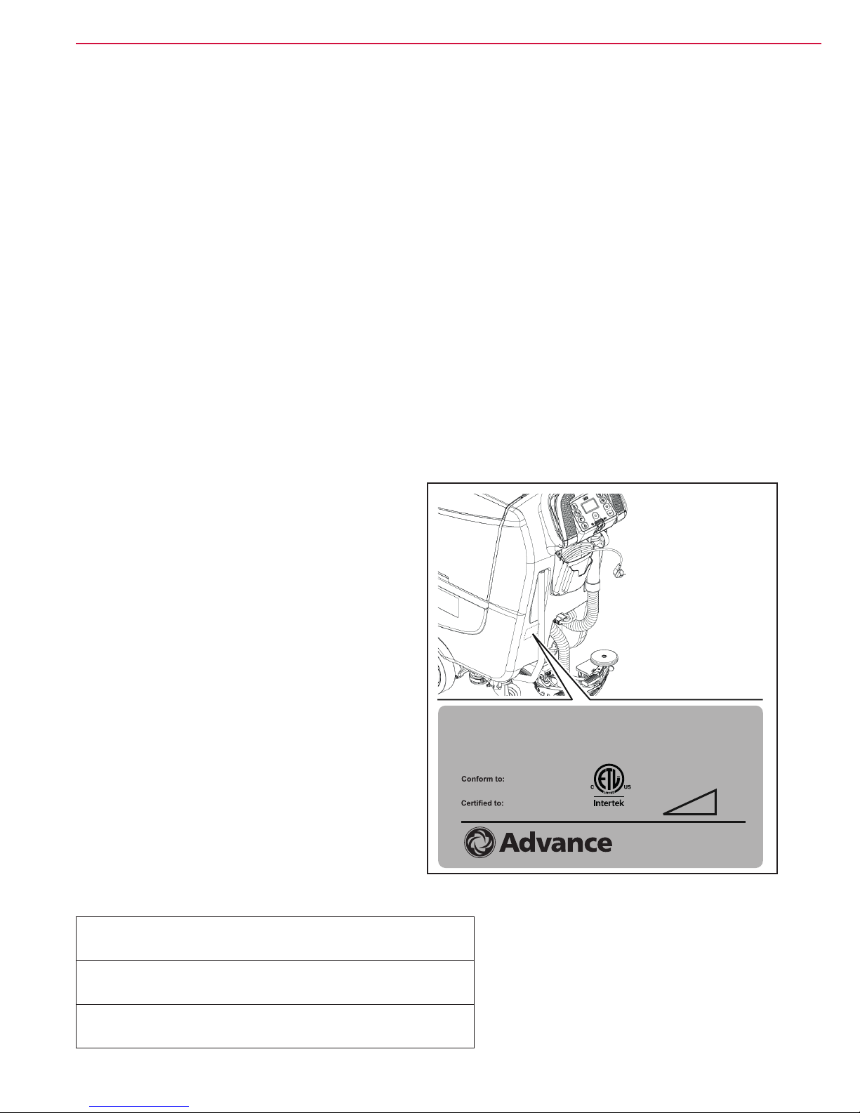
Serial Number Label
Reference to Figure 1
The machine serial number and model name are
marked on the plate (see the example to the side).
Product code and year of production are marked on
the same plate.
This information is useful when requiring machine
spare parts. Use the following table to write down
the machine identication data.
Model: Scrubber-Dryer SC500 20 B
Prod. Nr: 9087352020
GVW: 207 kg/456 lb
21 A Charg.100-240Va c 50-60 Hz
Type E Scrubber Dryer
UL 583
CSA C22.2 N.68-92
A Nilfisk-Advance Brand
IPX4
3084826
Serial No: ..................
Date code: .......
LpA = 63 dB(A)
Battery 24 Vdc
2%
“Made in Hungary”
Nilfisk-Advance, Inc.
Plymouth, MN, USA
www.advance-us.com
MACHINE model .............................................................................................
PRODUCT code ..............................................................................................
MACHINE serial number .................................................................................
Figure 1
Page 7
Service Manual – SC500
General Information
Safety
The following symbols indicate potentially dangerous situations. Always read this information carefully and
take all necessary precautions to safeguard people and property.
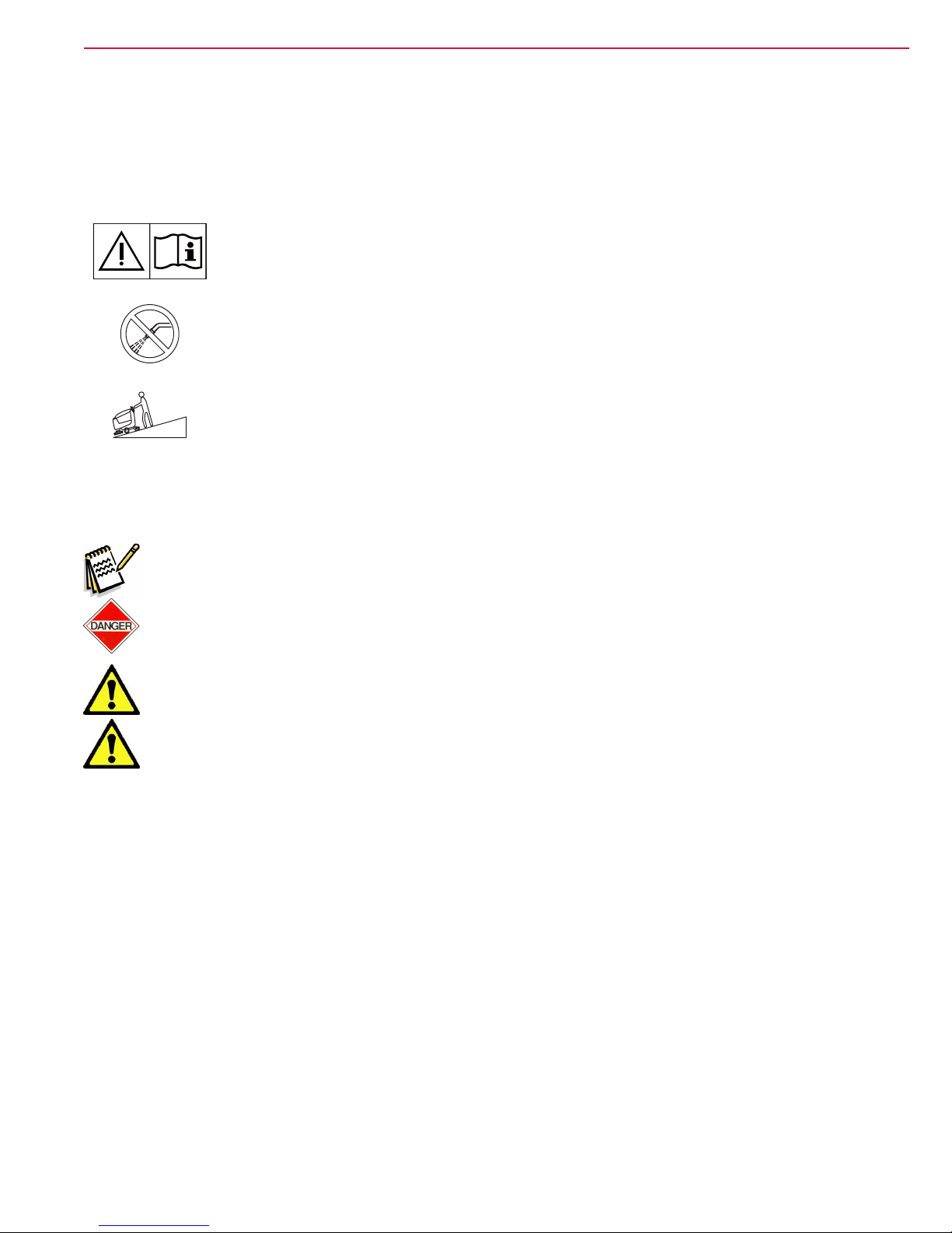
Visible Symbols on the Machine
Warning! Carefully read all the instructions before performing any operation on the
machine.
Warning! Do not wash the machine with direct or pressurized water jets.
Warning! Do not use the machine on slopes with a gradient exceeding the
max.2%
specications.
6
Symbols
Note: It indicates a remark related to important or useful functions.
Danger! It indicates a dangerous situation with risk of death for the operator.
Warning! It indicates a potential risk of injury for people or damage to objects.
Caution! It indicates a caution related to important or useful functions.
Page 8

Service Manual – SC500
General Information
General Instructions
Specic warnings and cautions to inform about potential damages to people and machine are shown below.
Warning! Make sure to follow the safety precautions to avoid situations that may lead to
serious injuries.
• Before performing any maintenance, repair, cleaning or replacement procedure, remove the ignition key
and disconnect the battery connector.
• This machine must be used by properly trained operators only.
• Do not wear jewels when working near electrical components.
• Do not work under the lifted machine without supporting it with safety stands.
• Do not operate the machine near toxic, dangerous, ammable and/or explosive powders, liquids or vapors:
This machine is not suitable for collecting dangerous powders.
• When using lead (WET) batteries, keep sparks, ames and smoking materials away from the batteries.
During the normal operation explosive gases are released.
• When using lead (WET) batteries, battery charging produces highly explosive hydrogen gas. During battery charging, lift the recovery tank and perform this procedure in well-ventilated areas and away from
naked ames.
Caution! Make sure to follow the safety precautions to avoid situations that may lead to
serious injuries, damages to materials or equipments.
7
• Carefully read all the instructions before performing any maintenance/repair procedure.
• The machine ignition key has a built-in magnet. Do not place objects having magnetic bands (such as
credit cards, electronic keys, phone cards) near the key. The built-in magnet can damage or erase the data
stored on the magnetic bands.
• Before using the battery charger, ensure that frequency and voltage values, indicated on the machine serial number plate, match the electrical mains voltage.
• Do not pull or carry the machine by the battery charger cable and never use the battery charger cable as
a handle. Do not close a door on the battery charger cable, or pull the battery charger cable around sharp
edges or corners. Do not run the machine on the battery charger cable.
• Keep the battery charger cable away from heated surfaces.
• Do not charge the batteries if the battery charger cable or the plug are damaged.
• To reduce the risk of re, electric shock, or injury, do not leave the machine unattended when it is
plugged in. Before performing any maintenance procedure, disconnect the battery charger cable from the
electrical mains.
• Do not smoke while charging the batteries.
• To avoid any unauthorized use of the machine, remove the ignition key.
• Do not leave the machine unattended without being sure that it cannot move independently.
• Always protect the machine against the sun, rain and bad weather, both under operation and inactivity
condition. Store the machine indoors, in a dry place: This machine must be used in dry conditions, it must
not be used or kept outdoors in wet conditions.
• Before using the machine, close all doors and/or covers as shown in the User Manual.
• This machine is not intended for use by persons (including children) with reduced physical, sensory or
mental capabilities, or lack of experience and knowledge, unless they have been given supervision or
instruction concerning use of the machine by a person responsible for they safety.
• Children should be supervised to ensure that they do not play with the machine.
• Close attention is necessary when used near children. Use only as shown in this Manual. Use only Nilsk
or Advance recommended accessories.
• Check the machine carefully before each use, always check that all the components have been properly
assembled before use. If the machine is not perfectly assembled it can cause damages to people and properties.
• Take all necessary precautions to prevent hair, jewels and loose clothes from being caught by the machine
moving parts.
• Do not use the machine on incline.
• Do not tilt the machine more than the angle indicated on the machine itself, in order to prevent instabil-
ity.
Page 9

Service Manual – SC500
General Information
• Do not use the machine in particularly dusty areas.
• Use the machine only where a proper lighting is provided.
• While using this machine, take care not to cause damage to people or objects.
• Do not bump into shelves or scaffoldings, especially where there is a risk of falling objects.
• Do not lean liquid containers on the machine, use the relevant can holder.
• The machine operating temperature must be between 32°F and 104°F (0°C and +40°C).
• The machine storage temperature must be between 32°F and 104°F (0°C and +40°C).
• The humidity must be between 30% and 95%.
• When using oor cleaning detergents, follow the instructions on the labels of the detergent bottles.
• To handle oor cleaning detergents, wear suitable gloves and protections.
• Do not use the machine as a means of transport.
• Do not allow the brush/pad to operate while the machine is stationary to avoid damaging the oor.
• In case of re, use a powder re extinguisher, not a water one.
• Do not tamper with the machine safety guards and follow the ordinary maintenance instructions scrupu-
lously.
• Do not allow any object to enter into the openings. Do not use the machine if the openings are clogged.
Always keep the openings free from dust, hairs and any other foreign material which could reduce the air
ow.
• Do not remove or modify the plates afxed to the machine.
• When the machine is to be pushed for service reasons (missing or discharged batteries, etc.), the speed
must not exceed 2.5 mi/h (4 km/h).
• This machine cannot be used on roads or public streets.
• Pay attention during machine transportation when temperature is below freezing point. The water in the
recovery tank or in the hoses could freeze and seriously damage the machine.
• Use brushes and pads supplied with the machine or those specied in the User Manual. Using other
brushes or pads could reduce safety.
• In case of machine malfunctions, ensure that these are not due to lack of maintenance. If necessary, request assistance from the authorised personnel or from an authorised Service Center.
• If parts must be replaced, require ORIGINAL spare parts from an Authorised Dealer or Retailer.
• To ensure machine proper and safe operation, the scheduled maintenance shown in the relevant chapter
of this Manual, must be performed by the authorised personnel or by an authorised Service Center.
• Do not wash the machine with direct or pressurised water jets, or with corrosive substances.
• The machine must be disposed of properly, because of the presence of toxic-harmful materials (batteries,
etc.), which are subject to standards that require disposal in special centres (see Scrapping chapter).
8
Page 10

Service Manual – SC500
Machine Lifting
Warning! Do not work under the lifted machine without supporting it with safety stands.
Machine Transportation
Warning! Before transporting the machine, make sure that:
All covers are closed.
The recovery tank and the detergent tank are empty.
The batteries are disconnected.
The ignition key is removed.
General Information
9
The machine is securely fastened to the means of transport.
Page 11

Service Manual – SC500
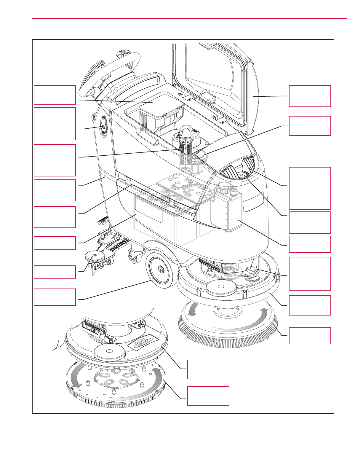
Machine Nomenclature (know your machine)
General Information
10
Can holder
Recovery tank
cover
Battery charger
Tank lifting
handle
Solution drain
and level check
hose
Serial number
plate/technical
data/conformity
certication
Solution lter
Solution tap
Drive handlebar
Forward/reverse
gear and activation
paddle
Control panel
Battery charger
cable
Battery charger
cable housing and
document holder
Recovery water
drain hose
Battery connector
(red)
Squeegee vacuum
hose
Squeegee lifting/
lowering pedal
Rear pivoting wheels
Figure 2
Squeegee adjusting
knob
Squeegee mounting
handwheels
Page 12
Service Manual – SC500
Machine Nomenclature (Continues)
General Information
11
Debris
collection tank
Detergent
solution tank
side ller cap
Vacuum grid
with automatic
shut-off oat
Solution tank
Recovery tank
Batteries
Recovery tank
cover
Vacuum system
motor
Detergent
solution tank
front ller
Water
removable ller
hose
EcoFlex
detergent tank
Squeegee
Front driving
wheels
Figure 3
Machine
straight forward
movement
adjusting knob
Disc brush deck
Brush
REV deck
REV brush
Page 13

Service Manual – SC500
Control panel (Disc deck)
Multifunction display and
operating information
General Information
12
EcoFlex system push-
button
Vacuum system
adjustment/deactivation
push-button
Detergent ow adjustment
push-button
Detergent percentage
adjustment push-button
Machine start/stop push-
button
Figure 4
Control panel (REV deck)
Multifunction display and
operating information
max.2%
1s
One-Touch Scrub ON/OFF
push-button
Brush release push-button
Machine speed adjustment
push-buttons
Machine ignition key
Operator key (grey)
Super user key (yellow)
EcoFlex system push-
button
Vacuum system
adjustment/deactivation
push-button
Detergent ow adjustment
push-button
Detergent percentage
adjustment push-button
Machine start/stop push-
button
Figure 5
max.2%
1s
One-Touch Scrub ON/OFF
push-button
REV function push-button
Machine speed adjustment
push-buttons
Machine ignition key
Operator key (grey)
Super user key (yellow)
Page 14
Service Manual – SC500
General Information
Service and Diagnostic Equipment
Besides a complete set of standard meters, the following instruments are necessary to perform fast checks and
repairs on Nilsk-Advance machines:
• Laptop computer charged with the current version of EzParts, Adobe Reader and (if possible) Internet
connection
• Digital Volt Meter (DVM)
• Amp clamp with possibility of making DC measurements
• Hydrometer
• Battery charge tester to check 12V batteries
• Static control wrist strap
• Dynamometric wrench set
• A copy of the User Manual and Spare Parts List of the machine to be serviced (provided with the machine
or available at www.advance-us.com or other Nilsk-Advance websites).
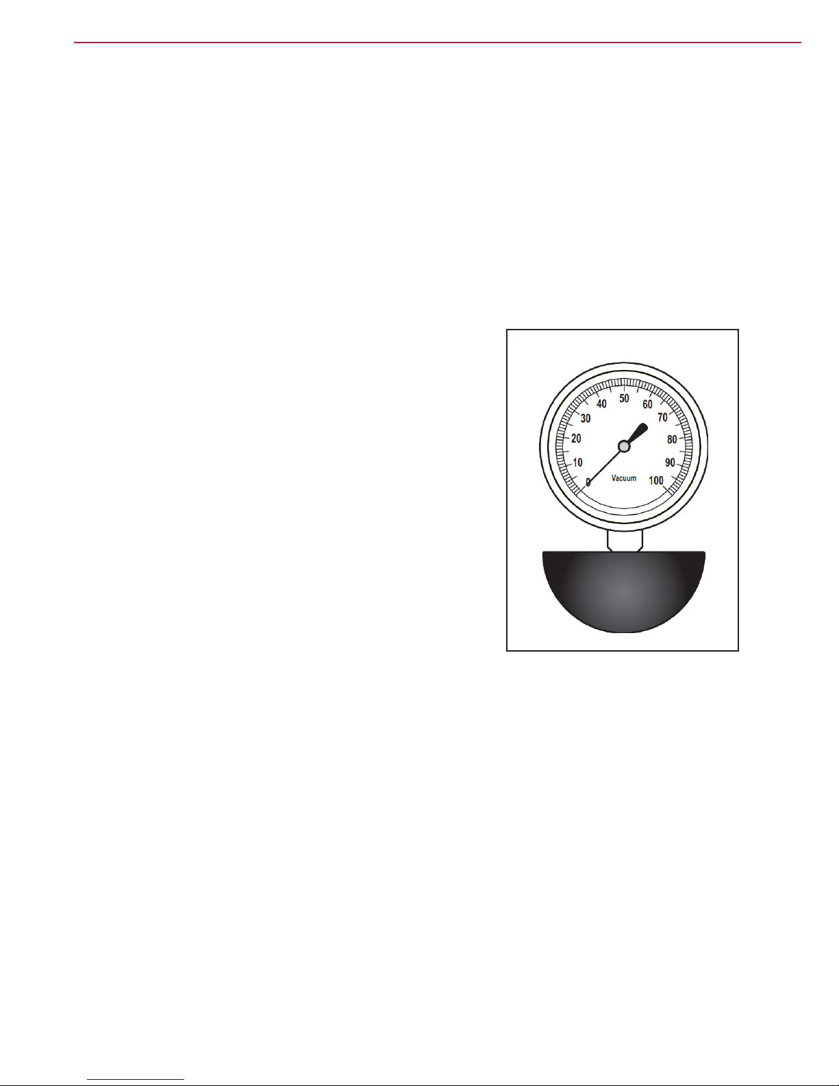
The following equipment is also available at Nilsk-Advance Centers:
• Vacuum water lift gauge, P/N 56205281
13
Figure 6
Page 15

Service Manual – SC500
Technical Data
General Information
14
Description / Model
Solution tank capacity 12 US gal (45 liters)
Recovery tank capacity 12 US gal (45 liters)
Machine length 50.3 in (1277 mm) 51.2 in (1302 mm)
Machine width with squeegee 28.3 in (720 mm)
Machine width without squeegee 21 in (532 mm) 21.2 in (538 mm)
Machine height 41.8 in (1063 mm)
Cleaning width 20 in (530 mm)
Driving wheel diameter 7.8 in (200 mm)
Driving wheel specic pressure on the oor (*) 101 psi (0.7 N/mm2)
Rear wheel diameter 3.1 in (80 mm)
Rear wheel specic pressure on the oor (*) 304 psi (2.1 N/mm2)
Brush/pad diameter 20 in (530/508 mm)
Brush pressure with extra-pressure function turned off 33 lb (15 kg) 49 lb (22 kg)
Brush pressure with extra-pressure function turned on 66 lb (30 kg) 66 lb (30 kg)
Solution ow values
EcoFlex system detergent percentage Ratio 1:500 ÷ 1:33 (0.25% ÷ 3%)
Sound pressure level at workstation (ISO 11201, ISO 4871, EN 60335-2-72) (LpA) 63 ± 3 dB(A) 65 ± 3 dB(A)
Sound pressure level at workstation in silent mode (LpA) 60 ± 3 dB(A) 61 ± 3 dB(A)
Machine sound power level (ISO 3744, ISO 4871, EN 60335-2-72) (LwA) 81 dB(A) 83 dB(A)
Vibration level at the operator’s arms (ISO 5349-1, EN 60335-2-72) < 98.4 in/s2 (< 2.5 m/s2)
Maximum gradient when working 2%
Drive system motor power 0.27 hp (200 W)
Drive speed (variable) 0 - 3.1 mi/h (0 - 5 km/h)
Vacuum system motor power 0.37 hp (280 W)
Vacuum system circuit capacity 29.9 in H2O (760 mm H2O)
Brush motor power 0.6 hp (450 W) 0.9 HP (670 W)
Brush rotation speed 155 rpm -
Total power draw (EN 60335-2-72) 0.7 hp (500 W)
IP protection class X4
Protection class (electric) III (I for the battery charger)
Battery compartment size 13.7x13.7x10.2 in (350x350x260 mm)
System voltage 24V
Standard batteries (2) 12V 105 AhC5
Battery charger 24V 13A
Operating time (standard batteries) (EN 60335-2-72) 3.5 hour
Weight without batteries and with empty tanks 187 lb (85 kg) 194 lb (88 kg)
Gross vehicle weight (GVW) 456 lb (207 kg) 463 lb (210 kg)
Shipping weight 256 lb (116 kg) 262 lb (119 kg)
Advance / Nilsk
SC500 20 B
0.75 cl/m / 1.5 cl/m
3.0 cl/m / 2.8 l/min
Advance
SC500 20R B
0.38 cl/m / 0.75 cl/m
1.5 cl/m / 2.8 l/min
(*) Machines have been tested under the following conditions:
◦ Battery maximum size
◦ Maximum brush and squeegee size
◦ Full detergent tank
◦ Optional equipment installed
◦ Wheel weight checked
◦ Print on the oor checked on cement for each single wheel
◦ Result expressed as maximum value for both front and rear wheels
Page 16

Service Manual – SC500
Dimensions
Nilsk SC500 Disc
41.8 in (1063 mm)
General Information
15
Figure 7
28.3 in (720 mm)
50.3 in (1277 mm)
21 in (532 mm)
Page 17

Service Manual – SC500
Dimensions (Continues)
Advance SC500 REV
41.8 in (1063 mm)
General Information
16
Figure 8
28.3 in (720 mm)
51.2 in (1302 mm)
21.2 in (538 mm)
Page 18

Service Manual – SC500
General Information
Maintenance
The lifespan of the machine and its maximum operating safety are ensured by correct and regular maintenance.
Warning! Read carefully the instructions in the Safety chapter before performing any
maintenance procedure.
The following tables provides the scheduled maintenance. The intervals shown may vary according to particular
working conditions, which are to be dened by the person in charge of the maintenance.
For instructions on maintenance procedures, see the following paragraphs.
Scheduled Maintenance Table
17
Procedure
Battery Charging
Squeegee Cleaning
Brush/pad cleaning
Recovery tank and debris tray cleaning, and cover
gasket check
EcoFlex system cleaning and draining
Squeegee blade check
Solution Filter Cleaning
Battery (WET) uid level check
Squeegee blade replacement
Brush motor carbon brush check or replacement
Drive system motor carbon brush check or replacement
Brush deck vibration-damper replacement (only for REV
version)
Daily, after using
the machine
Weekly
Every six
months
Yearly
Page 19

Chassis System 18Service Manual – SC500
Chassis System
Chassis (main parts)
The chassis function is primarily performed by the solution tank, the support housings for the wheels and working
mechanisms are integrated in the gear motor unit and the rear frame.
Reference to Figure 1
• Deck raising levers (see also Brush System, Disc and Brush System, REV)
• Frame integrated in the drive motor (see also Wheels System, Drive)
• Rear pivoting wheels support frame with squeegee raising/lowering system (see also Squeegee System)
Brush deck raising levers
Drive gear motor with
integrated frame
Rear pivoting wheels support frame with squeegee
Figure 1
raising/lowering system
Page 20
Control System
Functional Description
Control System 19Service Manual – SC500
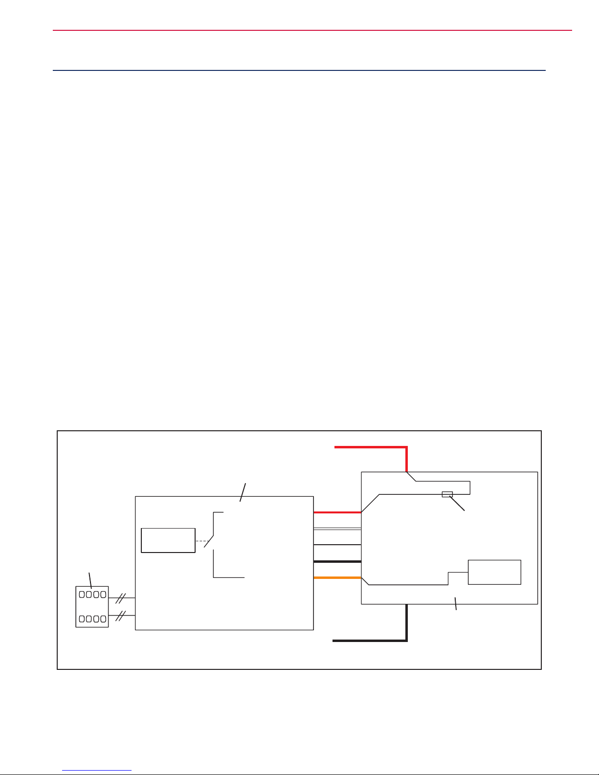
The architecture of the electronic control system for
the machine’s electrical components is composed of
a Function Board (EB1) and a Display Board (EB2),
in turn connected to a Dashboard Instrument Board
(EB3) which represents the main user interface.
The function board (EB1) manages all components
and drives the following components directly:
- Drive system motor (M3)
- Vacuum system motor (M2)
- Deck actuator (M5)
- Brush motor (M6)
- Solution ow solenoid valve (EV1)
- Detergent pump (M4)
The Display Board (EB2) serves mainly as an aggregator for all input signals (buttons) and outputs
(LEDs) from the Dashboard Instrument Board (EB3),
which it is connected to via 2 at cables.
Mounted on the Display Board (EB2) is also the LCD
display and the 2 sensors which detect the presence
and type of magnetic key inserted in the dashboard.
The display electronic board (EB2) sends all the input
and output signals of these components to the function electronic board (EB1) using 2-wire 2-way serial
communications protocol.
The system is completed by the on-board battery
charger which also uses a proprietary serial protocol
to communicate with the Function Board (EB1), in order to display its operating status (charging phase) to
the operator on the LCD display.
Wiring Diagram
DASHBOARD
INSTRUMENT
BOARD (EB3)
J3
J2
Figure 1
SCHEDA DISPLAY (EB2)
Dashboard power supply +
Dashboard serial +
Microprocessor
FCI DUFLEX (2.54 pitch) 8-way, male pins
FCI DUFLEX (2.54 pitch) 9-way, male pins
Dashboard serial -
Dashboard power supply -
Return from key
BATT +
J1.1
J1.2
J1.3
J1.4
J1.5
BATT -
B+
J3.1
Dashboard power supply +
J3.2
Dashboard serial +
J3.3
Dashboard serial -
J3.4
Dashboard power supply -
J3.5
Return from key
B-
SIGNAL CIRCUITS
FUSE (F2)
Microprocessor
FUNCTION ELECTRONIC
BOARD (EB1)
Page 21

Component Locations
• Function electronic board (EB1)
• Display board (EB2)
• Dashboard instrument board (EB3)
Control System 20Service Manual – SC500
Function electronic
board (EB1)
Figure 2
Dashboard instrument
board (EB3)
Display board (EB2)
Figure 3
Page 22

Control System 21Service Manual – SC500
Maintenance and Adjustments
Function Board (EB1) Alarm Codes
The function electronic board indicates a series of alarms in case of malfunction of one or more systems, and
in case of abnormal conditions detected in the input signals.
The alarms are shown on the display in the following format: ALARM <XX> <DESCRIPTION> (Figure 4).
Figure 4
In case the display is malfunctioning, the alarms are also repeated by the yellow and red diagnostic LEDs
(Figure 5) on the function board (EB1), as indicated in the following tables.
Figure 5
General alarms
Alarm on Function Board - FLASHING YELLOW + RED LEDS
Alarm code
-------------------------Description
G2
-----------------------
EEPROM
ERROR
No.
Flashes
Meaning Condition Effect
2 EEPROM error EEPROM error Function block
+ Default setting
reset
Service Suggestions
If the machine continues to function after
G2 has been displayed, this may have
been caused by a signicant external
electromagnetic disturbance.
1. Check that the settings and parameters
(see pages 29 - 30) are correct (they
may have returned to their defaults). If
the error persists, the board must be
replaced.
Page 23

Function Board (EB1) Alarm Codes (Continues)
General alarms
Alarm on Function Board - FLASHING YELLOW + RED LEDS
Alarm code
-------------------------Description
G3
-----------------------
MAIN FUSE
FAILURE
G4
----------------------BATTERY LOW
VOLTAGE
G5
-----------------------
BATTERY
OVERVOLTAGE
No.
Flashes
Meaning Condition Effect
3 Blown F2 fuse. Blown F2 fuse. Function block.
4 Undervoltage. The battery voltage
5 Excessive
battery voltage.
remains below 18.4V
for over 10 seconds (for
WET CELL batteries,
19.6V for GEL-AGM
batteries).
Battery voltage over 32V. Function block.
Function block.
Control System 22Service Manual – SC500
Service Suggestions
F2 is a safety fuse primarily included to
prevent a short circuit or serious damage
to the board causing currents such as to
melt cables and/or cause smoke or re. If
F2 has blown, this is usually indicative of
serious damage to the board.
1. Removing the cover should allow
you to understand the extent of the
damage, but the solution in any case
should be to replace the board.
2. Try replacing fuse F2 only if there is no
clear damage to the board and wiring.
3. Ensure you tighten the fuse contacts
correctly.
1. Check the battery voltage under
no-load conditions and under load.
Replace the faulty battery/batteries if
necessary.
2. Recharge the batteries by performing a
complete charging cycle.
Check the voltage of the installed batteries
and that the terminals are correctly
tightened.
G6
----------------------HARDWARE
FAILURE
G7
----------------------HARDWARE
FAILURE
6 Serial
communication
error with
dashboard
instrument board.
7 General relay
fault.
No signal or error
in communications
decoding between the
Function Board (EB1)
and the Display Board
(EB2).
Relay closes or closed at
start-up.
No block.
Function block.
1. Check the 5 cables from the 6-way
dashboard instrument board connector
to connector J3 pins 1, 2, 3, 4.
2. If there is continuity, the dashboard
instrument board must be replaced.
Replace the board.
Page 24

Function Board (EB1) Alarm Codes (Continues)
Function electronic board alarms
Alarm on Function Board - FLASHING RED LED
Alarm code
-------------------------Description
F2
----------------------BRUSH MOTOR
OVERLOAD
F3
-----------------------
VACUUM
MOTOR
OVERLOAD
F4
-----------------------
DECK
ACTUATOR
FAILURE
F5
----------------------HARDWARE
FAILURE
F6
-----------------------
PRESSURE
GAUGE
FAILURE
F7
----------------------OVERHEATING
F8
----------------------BRUSH MOTOR
FAILURE
F9
-----------------------
VACUUM
MOTOR
FAILURE
No.
ashes
board
Meaning Condition Effect
on
2 BRUSH motor
amperometric
protection.
3 VACUUM
SYSTEM
amperometric
protection.
4 DECK
ACTUATOR
overcurrent.
5 Short circuit on
the vacuum or
brush motor drive
MOSFET.
6 PRESSURE
GAUGE
FAILURE
(Not used)
7 Motor drive
section thermal
cut-out.
8 Brush motor
output short
circuit.
9 Vacuum
motor output
overcurrent.
The motor current is
greater than the value of
the parameter (see page
29 - 30) VS1
The current draw of the
vacuum motor is greater
than 30A for over 10
seconds.
Current greater than 4A
detected for more than 1
second.
MOSFET short circuit. Function block.
- -
The heatsink on the
board has reached a
temperature of 194°F
(90°C).
I > 150A for 20µsec. Function block.
I > 150A for 20µsec. Function block.
Brush motor
output stop.
Vacuum system
block.
Brush function
block.
Function block.
Control System 23Service Manual – SC500
Service Suggestions
Check the current draw of the brush motor.
It should remain below the value set in the
parameter “VS1” during operation.
1. Check for any debris in the vacuum
motor.
2. Check that the motor rotor turns freely.
3. Replace the vacuum motor if
necessary.
1. Check that there is no friction on
the brush deck linkage; lubricate if
necessary.
2. Check that the actuator and deck
travel is not blocked by mechanical
obstructions.
3. If the problem persists, replace the
actuator.
1. Check that there are no short circuits in
the motor wiring.
2. Replace the board.
-
Check the vacuum and brush motor power
draw and that the openings of the electrical compartment are not blocked.
Check for short circuits in the wiring or
motor.
Check for short circuits in the wiring or
motor.
Page 25

Function Board (EB1) Alarm Codes (Continues)
Drive system alarms
Alarm on Function Board - FLASHING YELLOW LED
Alarm code
-------------------------Description
T2
-----------------------
DRIVE MOTOR
OVERLOAD
T3
----------------------RELEASE THE
PADDLE !
T4
----------------------PADDLE INPUT
FAILURE
T5
----------------------HARDWARE
FAILURE
No.
ashes
board
Meaning Condition
on
2 Amperometric
protection
intervention.
3 Paddle not in rest
position when
board is turned
on.
4 Incorrect voltage
measured at
the paddle
potentiometer
input.
5 Drive system
power section
damage
Drive motor current
draw greater than the
parameter (see page 29 -
30) “INOM” for more than
the parameter (see page
29 - 30) “TMAX”.
Voltage on J1.2 of board
EB2 out of range 1.29V
- 1.49V with respect to
- BAT.
Voltage on J1.2 of board
EB2 above 3V.
MOSFET short circuit.
Control System 24Service Manual – SC500
Effect
Drive blocked. Check the current draw of the drive motor
Drive blocked. Check that the paddle moves correctly,
Drive blocked. 1. Check the connection of the
Drive blocked. 1. Check that the cables of the gear
Service Suggestions
(this should be around 6-8amps without
load and remain below 10-12amps during
operation).
lubricating if necessary; check the linkage
and potentiometer.
potentiometer to the board.
2. Replace the potentiometer.
3. Replace the display board.
motor are not short circuited (try
disconnecting the connectors from
contacts M1 and M2) and try starting
the machine and pressing the pedal
again
2. If the alarm persists, replace the board
T6
-----------------------
DRIVE MOTOR
FAILURE
T7
----------------------OVERHEATING
6 Overcurrent
(motor D.C.)
7 Drive motor drive
section thermal
cut-out.
Drive motor current
draw greater than 1.5
times the value of the
parameter (see page 29 -
30) “IMAX”.
The heatsink on the
board has reached a
temperature of 194°F
(90°C).
Drive blocked. 1. Check that the gear motor cables are
not short circuited
2. Check that the motor of the gear
motor unit is not short circuited (the
impedance of the motor should be
around 0.6 – 0.8 Ohm)
3. If necessary, replace the gear motor
unit motor
Drive blocked. 1. Check the drive motor power draw
and that the openings of the electrical
compartment are not blocked.
2. If everything is within normal
parameters, this may simply have been
caused by extreme working conditions
such as: Ambient temperature over
86°F (>30°C), sloping working sections.
Simply leave the system to cool and
turn the machine back on.
All alarms of the drive system operate by cutting the power supply to the gear motor unit motor until the KEY input is reset
(with the exception of alarm T3 which is reset as soon as the input voltage of the paddle potentiometer returns within the val-
ues corresponding to “machine stopped”). In case of simultaneous errors, the one with greater priority is shown rst (priority
order is opposite to the number of ashes).
Page 26

Function Board (EB1) Alarm Codes (Continues)
On-board Battery Charger Alarms
Alarm code
-------------------------Description
C1
----------------------CHARGER
COMMUNICATION
C2
-----------------------
BATTERY
OVERVOLTAGE
C4
----------------------CHARGING
TIME I EXPIRED
C5
----------------------CHARGING
TIME II
EXPIRED
C6
----------------------CHARGER
FAULT
Meaning Condition
Communication
problem between
the battery
charger and
function board.
Battery
overvoltage.
Charging phase I
expired.
Charging phase
II expired.
Battery charger
internal short
circuit.
No signal from battery
charger via gate J4.4 for
over 3 seconds.
Battery voltage over 32V.
Battery excessively
discharged or at end of
life cycle.
Battery excessively
discharged or at end of
life cycle.
Battery charger internal
short circuit.
Effect
The battery charger
is performing the
standard recharging
cycle for generic
GEL/AGM batteries.
Battery charger
block.
Battery charger
block.
Battery charger
block.
Battery charger
block.
Control System 25Service Manual – SC500
Service Suggestions
Check the wiring between the battery charger
and function board.
1. Check the connections of the batteries and
the voltage of the installed batteries.
2. Disconnect and reconnect the battery
charger.
If the problem persists, replace the batteries.
If the problem persists, replace the batteries.
Replace the battery charger.
Page 27
Control System 26Service Manual – SC500
Black-box: Recording of Alarms, Parameters (see pages 29-30), Partial Operating Time
Counter
The alarms activated during normal machine operation are stored and can be read in the corresponding log
(Alarm Log Screen).
Display, Main Screen
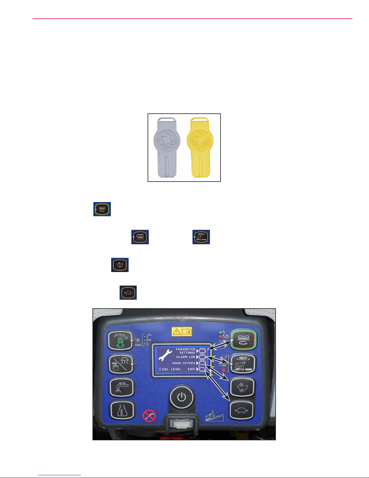
1. Insert the Super User (yellow) key in place of the operator (grey) key (Figure 6) to access the main
screen (Figure 7) of the multifunction display.
Figure 6
2. Press One-Touch push-button to change the machine settings (see Machine Settings Screen
section).
3. Press the brush release button or REV button to check for any stored machine alarms (see
Alarms Log Screen section).
4. Press the “hare” button to check the machine’s hours of operation (see Operating Time Counter
Screen section).
5. Press the “tortoise” button to exit service mode and return to operator mode.
Figure 7
Page 28

Control System 27Service Manual – SC500
Display, Alarms Log Screen
The alarms log screen (Figure 8) function allows you to check any alarms stored on the machine.
To return to the main screen (Figure 6), press the One-Touch button repeatedly.
Figure 8
Each alarm (See table of alarms in the Function Board Alarm Codes section) is stored along with the working
hour (machine operating time counter) at which it occurred and all alarms are recorded in the order in which
they occurred, from the most recent to the oldest.
The memory holds up to 20 alarm records, after which the oldest are overwritten when new alarms occur.
Improper uses of the batteries or battery charger are also recorded, as in the following table:
On-board Battery Charger Alarms
Alarm code
-------------------------Description
GB-N
-----------------------
CONTINUOUS
LOW BATTERY
VOLTAGE
GC
----------------------CHARGER
DISCONN
BEFORE END
CYCLE
GD-N
----------------------CHARGING
TIME LESS
THAN 4 HOURS
Meaning Condition
Time of
continuous use
with discharged
batteries
Charging cycle
interrupted
before
completion
Charging phase
duration
“N” is the number of hours from key on to off
when the battery level is below 20.4V for WET
CELL (21.6 for AGM) batteries. This event is not
recorded if the usage time is below 10 minutes.
Disconnection of battery charger before stage IV
= battery symbol with 3 segments lit steadily.
N = Number of hours from battery charger
connection to completion of PHASE II (red LED
on) if < 4
Effect
Incorrect use by customer. Risk of reduced
battery life.
Incorrect use by customer. Risk of reduced
battery life.
Incorrect use by customer. Risk of reduced
battery life.
Page 29

Control System 28Service Manual – SC500
Display, Machine Settings Screen
The machine settings screen (Figure 9) functions allow you to customise some parameters described in the
following table of modiable parameters.
1. Press the “hare” button to increase the value of the current parameter.
2. Press the “tortoise” button to decrease the value of the current parameter.
3. Press the One-Touch button to move to the next parameter.
4. To return to the main screen (Figure 6), press the brush release button .
Figure 9
MODIFIABLE PARAMETERS
Code Description Min. Value Factory Setting Max. Value
CHM1 Detergent concentration level 1
CHM2 Detergent concentration level 2 1:500 (0.25 %) 1:125 (0.80 %) 1:33 (3 %)
P1/P3
P2/P3
P3 Level 3 solution ow rate
P4 Level 4 solution ow enable OFF OFF ON
SPT EcoFlex function timer 0 (disabled) 60 sec. 300 sec.
XPRES Brush deck extra pressure enable OFF ON ON
FVMIN Minimum forward speed 0 % 25 % 100 %
FVMAX Maximum forward speed 10 % 100 % 100 %
RVMAX Maximum reverse speed 10 % 30 % 50 %
BAT Installed battery type 0 1 5
TOFF Automatic shut-off time 0 (disabled) 300 sec. 600 sec.
BRGH Display contrast 5 20 50
VRID Vacuum power in silent mode 1 1 5
RPM (*) Reduced brush rpm activation threshold 5 9 20
RESET Restore factory settings for all parameters OFF OFF ON
Level 1 solution ow rate in relation to level 3
(see section “System for Flow Rate Regulation as Function of
Speed”)
Level 2 solution ow rate in relation to level 3
(see section “System for Flow Rate Regulation as Function of
Speed”)
DISC 1.0 cl/m 3.0 cl/m 5.0 cl/m
REV 1.0 cl/m 1.5 cl/m 5.0 cl/m
1:500 (0.25 %) 1:500 (0.25 %) 1:33 (3 %)
0 % 25 % 100 %
0 % 50 % 100 %
(*) Increase the value of this parameter to reduce the brush motor speed in a wider range of applications and
vice versa
Page 30

Control System 29Service Manual – SC500
Display, Machine Settings Screen (Continues)
The following parameters are displayed only when, on reaching the last parameter RESET, the One-Touch
button is pressed together with the EcoFlex and vacuum buttons.
If the One-Touch button is not pressed, the system will return to the rst parameter CHM1.
HIDDEN PARAMETERS
Code Description
TSERV Service advisory timer
AR Maximum acceleration ramp (sec.) 0.5 sec. 1.5 sec. 5 sec.
DR
IR
VS1 Brush 1 motor protection threshold 20A 30A 50A
VS2 Brush 2 motor protection threshold 20A 40A 50A
VDEAD Paddle potentiometer dead zone 0.0V 0.1V 1.0V
INOM Nominal drive current 10A 15A 15A
IMAX Maximum drive current 10A 45A 45A
TMAX Protection trip time for IMAX 0 sec. 12 sec. 60 sec.
Maximum deceleration
ramp (sec.)
Maximum deceleration ramp in
reverse (sec.)
DISC 0.5 sec. 1.5 sec. 8 sec.
REV 0.5 sec. 2.5 sec. 8 sec.
Min.
Value
0.5 sec. 0.5 sec. 5 sec.
Factory Setting
0 0 1000
Max.
Value
Meaning
Set to a value X greater than 0 if you wish the
“Service Advisory” icon to be displayed every
X hours of machine running time (according
to the main operating time counter). To
reset the hour counter for the icon display
countdown (until the next service advisory),
press the BURST and vacuum buttons for 10
seconds with the display on the “SERVICE
MENU” page.
Increase to obtain a less abrupt response
when accelerating, and vice versa.
Increase to obtain a less abrupt response
when decelerating, and vice versa.
WARNING: increasing this value increases
the braking distance.
This is the maximum current which can be
supplied to the disc brush deck.
WARNING: increasing this value increases
the risk of the motors overheating.
This is the maximum current which can be
supplied to the disc brush deck.
WARNING: increasing this value increases
the risk of the motors overheating.
This is the maximum current which can be
supplied to the cylindrical brush deck.
WARNING: increasing this value increases
the risk of the motors overheating.
Increase if the alarm T3 appears in the rest
position and it is not possible to adjust the
system’s mechanics. (Speed regulation will,
however, be more difcult to modulate)
This is the maximum continuous current
which can be supplied to the electric wheel
drive unit.
WARNING: increasing this value increases
the risk of the motor overheating.
This is the maximum instantaneous current
which can be supplied to the electric wheel
drive unit.
WARNING: increasing this value increases
the risk of the motor overheating.
This is the reaction time of the electric wheel
drive unit protection device when overloaded:
this parameter is used in conjunction
with IMAX to obtain the most appropriate
response curve for the overload protection
motor actuation system.
WARNING: increasing this value increases
the risk of the motor overheating.
Page 31

Control System 30Service Manual – SC500
System for Flow Rate Regulation as Function of Speed
Solution ow levels 1, 2 and 3 regulate the ow of detergent solution on the basis of the machine speed so as
to keep the quantity of solution dispensed per square metre of oor treated constant.
The reference ow level is level 3: based on the setting of the corresponding parameter P3, the opening time
of the solenoid valve (and of the detergent pump when tted) is regulated so that the quantity of solution in
centiliters per metre travelled by the machine is constant and equal to the value set in the parameter.
For example, for P3 = 3.0, the machine will dispense 3 centiliters of solution per metre travelled, which equates
(for the standard deck width of 530 mm) to 5.7 centiliters per square metre of oor treated.
Levels 1 and 2 are dened via the corresponding parameters P1 and P2 as a % of level 3.
For example, for P1 = 25 and P2 = 50, P1 and P2 are respectively ¼ (25%) and ½ (50%) of the reference ow
rate P3.
The default values (the same as in the example above) are summarized in the table, with the corresponding
ow rate values in liters per minute, dependent on machine speed, given as a reference.
Delta12 DISC detergent ow (as a function of speed) (standard setting)
Level 1 Level 2 Level 3
Liters/minute @ 1 km/h 0.2 0.3 0.5
Liters/minute @ 3 km/h 0.4 0.8 1.5
Liters/minute @ 5 km/h 0.6 1.3 2.5
Centiliters per metre cleaned (constant) 0.75 1.5 3
Centiliters per meter2 cleaned (Ø530 deck) 1.4 2.8 5.7
Level 4 (when enabled) is independent of any parameter and supplies the maximum possible quantity of solution as it keeps the solenoid valve of the supply system constantly open (with the brush rotating).
Delta12 DISC detergent ow rate
Level 4
Liters/minute - Tank full 3.5
Liters/minute - Average 2.5
Page 32

Control System 31Service Manual – SC500
Display, Operating Time Counter Screen
The operating time counter screen (Figure 10) function allows you to check the total accumulated hours of
work for each machine subsystem:
• (A) TOTAL counter (machine running time)
• (B) DRIVE counter (drive system usage time)
• (C) BRUSH counter (brush rotation system usage time)
• (D) VACUUM counter (vacuum system usage time)
To return to the main screen (Figure 6), press the One-Touch button.
A
B
C
D
Figure 10
Page 33

Removal and Installation
Function Board (EB1) Removal/Replacement
1. Drive the machine on a level oor.
2. Remove the operator key.
3. Disconnect the red battery connector.
4. Lift the recovery tank.
5. Remove the 7 screws and remove the electronic component compartment cover.
6. Disconnect the following connections sequentially (Figure 11):
◦ (A) and (B) Board power supply connection (B+) and (B-).
◦ (C) and D) Brush motor connection (BR+) and (BR-).
Control System 32Service Manual – SC500
D
B
B
A
Figure 11
C
A
7. Disconnect the following connections sequentially (Figure 12):
◦ (E) and (F) Drive system motor connection (M1) and (M2).
◦ (G) and (H) Vacuum motor connection (VA+) and (VA-).
E
F
G
E
H
D
C
G
Figure 12
F
H
Page 34

Function Board (EB1) Removal/Replacement (Continues)
8. Disconnect the following connections sequentially (Figure 13):
◦ (I) Deck actuator and detergent pump connection (J1).
◦ (J) Solenoid valve connection (J2).
◦ (K) Display board connection (J3).
◦ (L) Battery charger connection (J4).
◦ (M) Detergent level sensor connection (J5).
◦ (N) Connection (J6).
Control System 33Service Manual – SC500
I
K
L
N
M
J
Figure 13
9. Unscrew the 4 retaining screws (O) and carefully remove the function board (Figure 14).
OO
I
K
L
N
M
J
Figure 14
10. Assemble the components in the reverse order of disassembly.
OO
Page 35

Control System 34Service Manual – SC500
Display Board (EB2) and Dashboard Instrument Board (EB3) Removal/Replacement
Display board
1. Drive the machine on a level oor.
2. Remove the operator key.
3. Disconnect the red battery connector.
4. Unscrew the 2 screws (A) (Figure 15).
5. Release the retaining tab (B), then lift up and
remove the dashboard cover (C).
A
A
6. Disconnect the following connections
sequentially (Figure 16):
◦ (A) Speed potentiometer connection (J4).
◦ (B) Display board power supply connection
(J1).
◦ (C) Flat connection (J3).
◦ (D) Flat connection (J4).
7. Unscrew the 4 screws (E), then remove the
display board (F).
D
A
B
C
Figure 15
C
B
Figure 16
E
E
F
E
E
Page 36

Control System 35Service Manual – SC500
Display Board (EB2) and Dashboard Instrument Board (EB3) Removal/Replacement
(Continues)
Dashboard Instrument Board
8. Perform points 1 to 5 for removal of the display board.
9. Disconnect the following connections sequentially (Figure 17):
◦ (A) Flat connection (J3).
◦ (B) Flat connection (J4).
10. Carefully raise the dashboard instrument board (C), detaching it from the cover (D).
Assembly
11. Assemble the components in the reverse order of disassembly and note the following:
◦ Before fastening the dashboard instrument board (C), ensure that the at connections (A) and (B) are
correctly run through the slots in the cover (D), then glue the board to the cover itself.
Figure 17
B
CD
A
Page 37

Specications
Function Board (EB1) Connectors
(Figure 18) Power connections (Ø6mm male RADSOK terminals - AMPHENOL SK 200800532 101 or equivalent)
Ref. Description
B+ Electronic board power supply + in 24V 125A BAT+
B- Electronic board power supply - in 24V 125A BAT-
Electronic board
in/out
V ref. I max. Connected to
Control System 36Service Manual – SC500
Figure 18
(Figure 19) Drive connections (Ø3.6mm male RADSOK terminals - AMPHENOL P/N N01 036 6501 001 or equivalent)
Ref. Description
BR+ Brush motor + out 24V 50A M1+
BR- Brush motor - out 24V 50A M1-
Electronic board
in/out
V ref. I max. Connected to
Figure 19
Page 38

Function Board (EB1) Connectors (Continues)
(Figure 20) Drive connections (2-way male faston T-connectors, 6.3x0.8 – spacing 7.4mm)
Ref. Description
M1 Drive system motor + out 0-24V 45A M3+
M2 Drive system motor - out 0-24V 45A M3-
Electronic board
in/out
V ref. I max. Connected to
Control System 37Service Manual – SC500
Figure 20
(Figure 21) Vacuum connections (2-way male parallel faston connectors, 6.3x0.8 – spacing 6.5mm)
Ref. Description
VA+ Vacuum system power supply + out 10-24V 30A M2+
VA- Vacuum system power supply - out 0V 30A M2-
Electronic board
in/out
V ref. I max. Connected to
Figure 21
Page 39

Function Board (EB1) Connectors (Continues)
(Figure 22) J1: MOLEX MINIFIT type, 8-ways vertical
PIN Description Electronic board
in/out
1 Detergent pump power supply + out 24V <1A M4
2 Detergent pump power supply - out 0V <1A M4
3 Deck actuator power supply +/- out 0/24V 8A M5
4 Deck actuator power supply -/+ out 0/24V 8A M5
5 Power supply for ADV versions congurator out 0V <1A J1.6
6 ADV versions congurator return in 0V <1A J1.5
7 Power supply for deck congurator out 0V <1A J1.8
8 Deck congurator return in 0V <1A J1.7
V ref. I max. Connected to
Control System 38Service Manual – SC500
Figure 22
(Figure 23) J2: MOLEX MINIFIT type, 2-ways vertical
PIN Description Electronic board
in/out
1 Solenoid valve power supply + out 24V 1A EV1
2 Solenoid valve power supply - out 0V 1A EV1
V ref. I max. Connected to
Figure 23
Page 40

Function Board (EB1) Connectors (Continues)
(Figure 24) J3: MOLEX MINIFIT type, 6-ways vertical
PIN Description Electronic board
in/out
1 Dashboard power supply + out 24V <1A EB2.1
2 Dashboard serial + in/out 5V <1A EB2.2
3 Dashboard serial - in/out 0V <1A EB2.3
4 Dashboard power supply - out 0V <1A EB2.4
5 Return from key in 24V <1A EB2.5
6 Return from key (repetition) out 24V <1A -
V ref. I max. Connected to
Control System 39Service Manual – SC500
Figure 24
(Figure 25) J4: MOLEX MINIFIT type, 4-ways vertical
PIN Description Electronic board
Enabling from battery charger in 24V <1A CH.1
1
Power supply from battery charger in 24V <1A CH.2
2
Battery charger enabling power supply out 24V <1A CH.3
3
Battery charger data communication In/out 5V <1A CH.4
4
in/out
V ref. I max. Connected to
Figure 25
Page 41

Function Board (EB1) Connectors (Continues)
(Figure 26) J5: JST VHR-3N vertical 3-way
PIN Description Electronic board
in/out
1 Power supply for water level sensor + out 24V <1A S1.1
2 Water level sensor return in 0V <1A S1.2
3 Power supply for water level sensor - out 0V <1A S1.3
V ref. I max. Connected to
Control System 40Service Manual – SC500
Figure 26
Figure 27
(Figure 27) J6: JUMPER, 2-ways vertical
Page 42

Function Board (EB1) Connectors (Continues)
(Figure 28) J7: TYCO MODU II vertical 6-way
PIN Description Electronic board
1 +24V power supply out 24V <1A TRK.RD
2 +5V power supply out 5V <1A -
3 iButton input (CAN H channel) In (Out) 0V (0-5V) <1A TRK.YE
4 Ext. operating time counter enable (CAN
L channel)
5 Power supply - out 0V <1A TRK.BU
6 Machine on signal out 24V <1A TRK.BN
in/out
(In) Out 0V (0-24V) <1A TRK.WH
V ref. I max. Connected to
Control System 41Service Manual – SC500
Figure 28
Page 43

Display board (EB2) Connectors
(Figure 29) J1: MOLEX MINIFIT type, 6-ways vertical
Ref. Description
1 Power supply + in/out 24V <1A CFD12.J3.1
2 Dashboard serial + in/out 5V <1A CFD12.J3.2
3 Dashboard serial - in 0V <1A CFD12.J3.3
4 Power supply - out 0V <1A CFD12.J3.4
5 Key signal return (KEY0) out 24V <1A CFD12.J3.5
6 Key signal return (KEY0)
Electronic board
in/out
in
V ref. I max. Connected to
24V <1A -
Control System 42Service Manual – SC500
Figure 29
(Figure 30) J2: FCI DUFLEX (2.54 pitch) 9-way, male pins
Ref. Description
1 Power supply - common out 0V <1A
2 ON/OFF button (P0) in 0V <1A
3 DETERGENT MIX button (P4) in 0V <1A
4 EDS button (P3) in 0V <1A
5 VACUUM button (P2) in 0V <1A
6 VACUUM function LED (LD2)
7 SPOT function LED (LD1)
8 SPOT button (P1)
9 DS versions congurator
Electronic board
in/out
out
out
in
in
V ref. I max.
5V <1A
5V <1A
0V <1A
0V <1A
Figure 30
Page 44

Display board (EB2) Connectors (Continues)
(Figure 31) J3: FCI DUFLEX (2.54 pitch) 8-way, male pins
Ref. Description
1 Power supply - common out 0V <1A
2 SP / EXTRAPR function LED (red)(LD3R) out 5V <1A
3 SP / EXTRAPR function LED (green)(LD3V) out 5V <1A
4 BRUSH RELEASE function LED (LD4) out 5V <1A
5 BRUSH RELEASE switch (P6) in 0V <1A
6 INCREASE SPEED button (P7)
7 DECREASE SPEED button (P8)
8 ONETOUCH / EXTRAPR. button (P5)
Electronic board
in/out
in
in
in
V ref. I max.
0V <1A
0V <1A
0V <1A
Control System 43Service Manual – SC500
Figure 31
(Figure 32) J4: JST VH vertical, 3-way (B 3P-VH)
PIN Description
1 VR1 potentiometer power supply + Out 3V <1A VR1.1
2 VR1 potentiometer return In 0-3V <1A VR1.2
3 VR1 potentiometer power supply - out 0V <1A VR1.3
Electronic board
in/out
V ref. I max. Connected to
Figure 32
Page 45

Control System 44Service Manual – SC500
Shop Measurements
The following tables contain some “real world” shop voltage measurements to help you recognize what “normal” looks like. All voltage values were measured with the black (Negative) voltmeter lead connected to the
main battery negative unless otherwise specied.
Shop Measurements - Function Board (EB1)
Battery volts at battery, key on = 25.03V
Power Supply
Figure 33
PIN Color Description Measured Comments
B+ Red Electronic board power supply + 24.5v Vacuum on
B- Black Electronic board power supply - 0.035vV Vacuum on
Page 46

Shop Measurements - Function Board (EB1) (continues)
Brush Motor
Figure 34
Control System 45Service Manual – SC500
PIN Color Description Measured Comments
BR+ Red Brush motor + 24.4V (off),
24.2V (on)
BR- Blue Brush motor - 24.4V (off),
0.15v (on without RPM control activated)
5.8v (on with RPM Control Active – set at 20)
Drive System Motor
Constant Positive
PWM Battery
Negative
Figure 35
PIN Color Circuit Description Measured
M1 Red Drive system motor + 5.62v 12.7v 10.9v 21.8v 8.7v
M2 Gray Drive system motor - 5.61 1.95 16.00 8.9v 13.5v
M1 to
M2
Neutral Fwd -
Initial
0.001v 6.1v -2.5v 22.6 -7.4
Reverse Initial
FWD Max REV Max
Page 47

Shop Measurements - Function Board (EB1) (continues)
Vacuum Motor
Figure 36
Control System 46Service Manual – SC500
PIN Color Description Measured Comments
VA+ Red Vacuum system power supply + 24.8v (off)
24.4v (on)
VA- Blue Vacuum system power supply - 24.56 (off)
1.36v (on High)
9.69v (on Quiet mode VRID parameter = 1)
Constant Positive
1.02 Running, 9.56
Quiet Mode
Page 48

Shop Measurements - Function Board (EB1) (continues)
J1
Figure 37
Control System 47Service Manual – SC500
PIN Color Circuit Description Measured Comments
1 Red Detergent pump power supply + 24.9v (off) No change seen on
2 Gray Detergent pump power supply - 24.9v (off)
3 White Deck actuator power supply +/- 24.8v (Stationary)
4 Blue Deck actuator power supply -/+ 24.8v (stationary)
5 Green Power supply for ADV versions
congurator
6 Green ADV versions congurator return 0.001 (Loop not cut)
7 Red Power supply for deck congurator 0.001
8 Red Deck congurator return 0.001 (Loop not cut)
Momentary drop to 0 when on.
0.18v (going up)
12v (going up near top)
24.8v (going down to scrub or Ex press)
12.6v (Reset Up)
Stationary: 0v
Transport to Scrub: 24.8v
Scurb to Ex Press: 24.8v then 12v near end
of travel.
Ex Press to Scrub: -24.8v
Scrub to Transport: -24.8v then -12v near
end of travel
Reset to transport:-12.5v entire range
0.03v (Transport to scrub)
Scrub to EX Press – Initial 0.03v then 12v
near bottom
24.8v( Ex press to scrub)
Scrub to Transport – 24.8v
0.001
4.98v (Open loop)
4.98v (Open loop)
voltmeter when the
pump pulsed.
Voltmeter reading
momentarily jumped.
Too fast to settle into
a range and value.
Reference to J1.3
Loop not cut
Loop not cut
Page 49

Shop Measurements - Function Board (EB1) (continues)
J2
Figure 38
Control System 48Service Manual – SC500
PIN Color Circuit Description Measured Comments
1 Yellow Solenoid valve power supply + 24.4 (Off and On)
2 Purple Solenoid valve power supply - 24.4 (off)
Momentary drop (on)
Momentarily drops to
0v when on but it is
too fast for a DVOM
to read. The value
just momentarily
changes.
Page 50

Shop Measurements - Function Board (EB1) (continues)
J3
Figure 39
Control System 49Service Manual – SC500
PIN Color Circuit Description Measured Comments
1 Red Dashboard power supply + 24.9v On or Off
2 White Dashboard serial + 4.62v key on
3 Blk/Wh Dashboard serial - 4.13v key on
4 Black Dashboard power supply - 0.001v key on
5 Orange Return from key 24.3v key inserted and power “on” Either the yellow or
6 Empty
0v key off
0v key off
gray key has the
same result. Note:
if no key, jumping
+24v here turns the
machine on.
Page 51

Shop Measurements - Function Board (EB1) (continues)
J4
Figure 40
Control System 50Service Manual – SC500
PIN Color Circuit Description Measured Comments
1 White Enabling from battery charger 24.8v Not Charging May see residual
2 Yellow Power supply from battery charger 0.136v Not charging
3 Brown Battery charger enabling power
supply
4 Green Battery charger data communication 4.98v when charger is rst plugged in. Then
26.1v Charging
24.8v key on or off Constant power
dropped to 4.6
voltage back-feeding
from the main board
here when charging.
whether charging or
not. Key on or off.
Page 52

Shop Measurements - Function Board (EB1) (continues)
J5
Figure 41
Control System 51Service Manual – SC500
PIN Color Circuit Description Measured Comments
1 Brown Power supply for water level sensor + 24.7v Key on
2 Black Water level sensor return 4.98
0.03v
3 Blue Power supply for water level sensor - 0.001
Tank < ½ full
Tank > ½ full
Page 53

Shop Measurements - Function Board (EB1) (continues)
J6
Figure 42
Control System 52Service Manual – SC500
Two way vertical jumper.
• What is this for? The J6 Jumper is used to congure the function board for the EcoFlex option.
• What does it mean if it is jumped? The function board is set for no EcoFlex
• What does it mean if it is open? The function board is set for EcoFlex
• Is there a measurable voltage on either of the pins when not jumped? Yes. 4.98v on pin near the LEDS on
the board.
Page 54

Control System 53Service Manual – SC500
Shop Measurements - Function Board (EB1) (continues)
J7
Measured machine did not have a wiring connector. Measurements were taken at each pin on the board.
Figure 43
PIN Color Circuit Description Measured Comments
1 +24V power supply 24.6
2 +5V power supply 5.00
3 iButton input (CAN H channel) 4.98
4 Ext. operating time counter enable
(CAN L channel)
5 Power supply - 0.001
6 Machine on signal 23.68
24.6
Page 55

Control System 54Service Manual – SC500
Shop Measurements - Display Board (EB2)
Measure and record the voltage at each of the function board pins. Always use battery negative as your reference point for your black voltmeter lead.
J1
Figure 44
PIN Color Circuit Description Measured Comments
1 Red Power supply + 24.6
2 White Dashboard serial + 4.62
3 Blk/Wh Dashboard serial - 4.12
4 Black Power supply - 0.003
5 Orange Key signal return (KEY0) 24.23
6
Page 56

Shop Measurements - Display Board (EB2) (continues)
J2 9 way ribbon connector
PIN 1 PIN 9
Figure 45
PIN Color Circuit Description Measured Comments
1 Power supply - common 0.003v .
2 ON/OFF button (P0) 24.2v Key off or key on
3 DETERGENT MIX button (P4) 3.14v Not pressed
4 EDS button (P3) (Solution Button) 3.14v Not pressed
5 VACUUM button (P2) 3.14v not pressed
6 VACUUM function LED (LD2) 0.007v LED off
7 SPOT function LED (LD1) 0.007v LED off
8 SPOT button (P1) (EcoFlex – Burst
of power)
9 DS versions congurator 3.14v
0.02v pressed
0.02v pressed
0.05v pressed
3.14v Not pressed
0.02v pressed
Control System 55Service Manual – SC500
.
Page 57

Shop Measurements - Display Board (EB2) (continues)
J3 8 way ribbon connector
PIN 1 PIN 8
Figure 46
PIN Color Circuit Description Measured Comments
1 Power supply - common 0.003v
2 SP / EXTRAPR function LED (red)
(LD3R)
3 SP / EXTRAPR function LED (green)
(LD3V)
4 BRUSH RELEASE function LED
(LD4)
5 BRUSH RELEASE switch (P6) 3.14v not pressed
6 INCREASE SPEED button (P7) 3.14v not pressed
7 DECREASE SPEED button (P8) 3.14v not pressed
8 ONETOUCH / EXTRAPR. button
(P5)
1.78v Red LED on
0.032v Red LED off
1.95v Grn LED on
0.032v Grn LED off
0.07v LED off
Pulsing when ashing
0.03v pressed
0.02v pressed
0.02v pressed
3.16v not pressed
0.04v pressed
Control System 56Service Manual – SC500
Page 58

Shop Measurements - Display Board (EB2) (continues)
J4 Potentiometer Connector
Figure 47
Control System 57Service Manual – SC500
PIN Color Circuit Description Measured Comments
1 Red VR1 potentiometer power supply + 2.675
2 White VR1 potentiometer return 1.45 (Neutral) 2.48 (Full Fwd Pin 2),
3 Black VR1 potentiometer power supply - 0.41 (Ground)
0.44 (Full Rev Pin 2)
Page 59

Electrical System
Functional Description
Electrical System 58Service Manual – SC500
The batteries (2 x 12V) are connected together in series by the cables.
The battery charger (CH) is connected to the machine
by two connectors (C) (power connection to the batteries) and C3 (4-way signal connection).
The grey and white cables (1 and 2 of connector C3) are
short circuited inside the battery charger CH when
this is not connected to the mains. If this connection is
not made, all machine functions are disabled.
If the optional battery charger has not been installed,
the relevant bridge must be used on connector C3.
Wiring Diagram
C1+
MAIN
BATTERY
CONNECTOR
C2.A
24V BATTERIES
(BAT)
24V
BATTERY CONNECTOR
The green cable (terminal 4 of connector C3) is the
data cable between board (EB1) and battery charger
(CH).
This connection allows the battery charger charging
curve to the be set directly from the machine dashboard and to view the operational state of the battery
charger during charging directly on the dashboard
display.
B+
J4.1
Enabling from battery charger
J4.1
SIGNAL CIRCUITS
FUSE (F2)
J4.2
Power supply from battery charger
J4.3
Battery charger enabling power supply
J4.4
Battery charger data communication
(**)
J4.3
(*)
BATTERY CHARGER (CH)
BATTERY CONNECTOR
C1-
Figure 1
(*) Optional for BASIC version
(**) Version without on-board battery charger
FUNCTION BOARD
FUSE (F1)
B-
FUNCTION
ELECTRONIC
BOARD (EB1)
Page 60

Component Locations
Electrical System 58Service Manual – SC500
• Function electronic board (EB1)
• Signal circuits fuse (F2)
• Function board fuse (F1)
• Battery charger (CH)
Function electronic
board (EB1)
Function board
fuse (F1)
• Battery connections
• Batteries (BAT)
• Battery connector (C1)
Battery charger (CH)
Signal circuits fuse
(F2)
Figure 2
Battery connections
Batteries (BAT)
Battery connector (C1)
Figure 3
Page 61

Electrical System 58Service Manual – SC500
Maintenance and Adjustments
Setting the Installed Battery Type
Set the machine and the on-board battery charger (where tted) on the basis of the type of battery to be installed by modifying the BAT parameter as indicated.
1. Insert the Super User (yellow) key in place of the operator (grey) key to access the main screen (Figure
4) of the multifunction display.
2. Press the One-Touch button to continue to the machine settings screen (Figure 5).
Figure 4
Figure 5
3. Press the One-Touch button until you reach the BAT parameter.
MODIFIABLE PARAMETERS
Code Description Min. Value Factory Setting Max. Value
BAT Installed battery type 0 1 5
4. Press the “hare” or “tortoise” button to modify the value of the BAT parameter as per the
following table:
Code BAT
Value Installed battery type
0 WET Wet cell batteries
1 GEL / AGM Generic GEL or AGM batteries
2 GEL EXIDE EXIDE®/SONNENSHINE brand GEL batteries
3 GEL OPTIMA OPTIMA brand GEL batteries
4 GEL DISCOVER DISCOVER® brand GEL batteries
5 GEL FULLRIVER FULLRIVER® brand GEL batteries
5. Press the brush release button to conrm the chosen parameter and return to the main screen
(Figure 4).
Page 62

Electrical System 58Service Manual – SC500
Battery installation
1. Remove the operator key.
2. Disconnect the red battery connector.
3. Lift the recovery tank cover and check that it is empty; if not, empty it using the drain hose.
4. Grasp the handle and carefully lift the recovery tank.
5. The machine is supplied with cables suitable to install 2 12V batteries.
6. Carefully lift the batteries until the relevant compartment, then place them properly.
7. Route and install the battery cable as shown in the diagram (Figure 6), then carefully tighten the nut on
each battery terminal.
8. Place the protection cap on each terminal, then connect the red battery connector.
9. Perform a complete battery charging cycle.
Battery Charging
Note: Chargethebatterieswhenthereisonlyoneashingsegmentdisplayedinthebattery
Caution! When the batteries are discharged, charge them as soon as possible, as that
12 V
12 V
Figure 6
symbol, or at the end of each shift. Keeping the batteries charged make their life last
longer.
condition makes their life shorter. Check for battery charge at least once a week.
Caution! If the machine is not equipped with on-board battery charger, choose an external
battery charger suitable for the type of batteries installed.
Page 63

Battery Charging (Continues)
Warning! When using lead (WET) batteries, battery charging produces highly explosive
hydrogen gas. Charge the batteries in well-ventilated areas and away from naked
ames. Do not smoke while charging the batteries. Keep the recovery tank raised
until the battery charging cycle is over.
Warning! Pay close attention when charging WET CELL batteries, as there may be battery uid
leakages. The battery uid is corrosive. If it comes in contact with skin or eyes, rinse
thoroughly with water and consult a physician.
Electrical System 58Service Manual – SC500
1. (For WET CELL batteries only) Check the level
of electrolyte inside the batteries. If necessary,
unscrew the caps and top up.
2. When the correct level is restored, close the caps
and clean the tops of the batteries.
Charging the Batteries with an External Battery
Charger
3. Check that the external battery charger is
suitable by referring to the relevant Manual.
The battery charger voltage rating must be 24V.
4. Disconnect the red battery connector and
connect it to the external battery charger.
5. Connect the battery charger to the electrical
mains.
6. After charging, disconnect the battery charger
from the electrical mains and from the battery
red connector.
7. Connect the battery connector to the machine.
8. Carefully lower the recovery tank.
10. When the rst or second segment from the left in
the battery symbol is ashing, this means that
the battery charger is charging the batteries.
11. When the third segment from the left in the
battery symbol is ashing, this means that the
battery charger is nishing the battery charging
cycle.
12. When all segments of the battery symbol
are steadily lit, the battery charging cycle is
complete.
13. Disconnect the battery charger plug from the
mains and place it in its holder.
14. Carefully lower the recovery tank.
Note: For further information about
the operation of the battery
charger, see the relevant
Manual.
Battery charging with battery charger installed on
the machine
9. Plug the battery charger into the mains
electricity supply (the mains voltage and
frequency must be compatible with the battery
charger values shown on the machine serial
number plate).
Note: When the battery charger is
connected to the electrical
mains, all machine functions
are automatically cut off.
Page 64

Battery Charge State Display
(Signicant levels for machine operation)
INDICATION
1 22V 22.2V Little remaining run time, no block.
2 20.4V 21.6V Brush OFF
3 19.4V 20.6V Vacuum system OFF
4 18.4V 19.6V Drive system OFF
TRANSITION THRESHOLD (VOLT)
WET GEL
CONSEQUENCE
Checking/Replacing Fuses
1. Drive the machine on a level oor.
2. Remove the operator key.
Electrical System 58Service Manual – SC500
3. Disconnect the red battery connector.
4. Lift the recovery tank.
5. Remove the 7 screws and remove the electronic component compartment cover.
6. Check/replace the following fuses (Figure 7):
◦ (F1) 100A midi fuse - function board (A).
◦ (F2) 3A blade fuse - Signal circuits (B).
7. Place the function electronic board assembly in its housing, tighten the mounting screws and install the
electronic component compartment cover.
B
A
A
B
Figure 7
Page 65

Electrical System 58Service Manual – SC500
Troubleshooting
See the other chapters for previously provided instructions for other electrical system components.
Trouble Possible Causes Remedy
The machine is not working Batteries (BAT) at or connections faulty Charge the batteries or clean the
The batteries (BAT) are broken Check the battery no-load voltage
The battery charger (CH) is broken Replace
The wiring harness is cut or pressed or short circuited Repair
Note: A damage to the battery charger or its connections can prevent the machine from
operating properly.
connections
Page 66

Specications
Battery compartment size (length x width x height) 13.7x13.7x10.2 in (350x350x260 mm)
Standard batteries (2) 12V 105 AhC5
Standard battery run time (capacity) 3.5 h
Model 24V 13A
Input voltage 85Vac÷264Vac, 50Hz÷60Hz
Battery charger
Charging procedure by microprocessor
Efciency > 85%
Environmental protection class IP30
Electrical System 58Service Manual – SC500
Page 67

Electrical System 66
Service Manual – SC500
General Wiring Diagram
SOLENOID VALVE
(EV1)
BRUSH DECK
ACTUATOR MOTOR
(M5)
DETERGENT PUMP
(M4)
DRIVE SYSTEM
MOTOR
(M3)
VACUUM SYSTEM
MOTOR
(M2)
BRUSH MOTOR
(M1)
M5
M4
M3
M2
M1
+
-
OUT
J5.3
J5.2
J5.1
J2.2
J2.1
J1.8
J1.7
J1.6
J1.5
J1.4
J1.3
J1.2
J1.1
J1.5
J1.4
J1.3
J1.2
J1.1
J3
J2
24V
J4.1
J4.2
J4.3
VR1 potentiometer power supply +
VR1 potentiometer return
VR1 potentiometer power supply -
M2
M1
VA-
VA+
BR-
BR+
Brush motor -
Brush motor +
Vacuum system power supply -
Vacuum system power supply +
Drive system motor -
Detergent pump power supply +
Detergent pump power supply -
Deck actuator power supply +/-
Deck actuator power supply -/+
Power supply for ADV versions configurator
ADV versions configurator return
Power supply for deck configurator
Deck configurator return
Solenoid valve power supply +
Solenoid valve power supply -
Power supply for water level sensor +
Water level sensor return
Power supply for water level sensor -
Drive system motor +
J3.1
J3.2
J3.3
J3.4
J3.5
J4.1
J4.2
J4.3
J4.1
J4.3
J4.4
J7.1
J7.4
J7.3
J7.5
J7.6
+24V power supply
External operating time counter enable (CAN L channel)
iButton input (CAN H channel)
Power supply -
Machine on signal
B-
B+
C1+
C1-
C2.A
24V BATTERIES
(BAT)
FUNCTION
ELECTRONIC
BOARD (EB1)
FUNCTION BOARD
FUSE (F1)
SIGNAL CIRCUITS
FUSE (F2)
WATER LEVEL
SENSOR (SW1)
DISPLAY BOARD (EB2)
DASHBOARD
INSTRUMENT
BOARD (EB3)
BATTERY CONNECTOR
MAIN
BATTERY
CONNECTOR
BATTERY CONNECTOR
TRACKUNIT (EB4)
BATTERY CHARGER (CH)
(**)
(*)
Dashboard power supply +
Electronic board power supply +
Electronic board power supply -
Dashboard serial +
Dashboard serial -
Dashboard power supply -
Return from key
FCI DUFLEX (2.54 pitch) 8-way, male pins
FCI DUFLEX (2.54 pitch) 9-way, male pins
Dashboard power supply +
Dashboard serial +
Dashboard serial -
Dashboard power supply -
Return from key
SPEED
POTENTIOMETER
(RV1)
Enabling from battery charger
Power supply from battery charger
Battery charger enabling power supply
Battery charger data communication
Figure 8
(*) Optional for BASIC version
(**) Version without on-board battery charger
Page 68

Recovery System
Functional Description
Recovery System 67Service Manual – SC500
The recovery system removes the dirty water from
the oor and pipes it to a recovery tank. When the
machine is running, the dirty water on the oor is col-
lected by the squeegee blades and collected through
the slots in the same, piped through the vacuum hose
and into the tank by the airow created by vacuum
motor (M2). The dirty water is piped into the recovery
tank, while the airow continues to the vacuum fan.
A tank with a grid collects the largest debris going
through the recovery tank hose.
The automatic oat in the vacuum grid stops vacuum
system motor (M2) from collecting any liquids.
When the automatic oat closes and shuts down the
vacuum system, the vacuum system motor noise will
increase and the oor will not be dried.
The vacuum system is activated automatically with the
One-Touch button . It can then be managed inde-
pendently via the vacuum button . The vacuum
system is activated in full power or silent mode depending on the last mode in use before the machine was
switched off. This mode can be changed by repeatedly
pressing the vacuum button . The various vacuum
modes are also displayed on the multifunction display.
When the recovery tank is full it can be emptied
through the drain hose.
Wiring Diagram
FUNCTION
ELECTRONIC
BOARD (EB1)
Figure 1
B+
Vacuum system power supply +
Vacuum system power supply -
B-
VA+
VA-
VACUUM
SYSTEM
MOTOR (M2)
M2
Page 69

Component Locations
• Recovery tank
• Recovery tank cover
• Cover gasket
• Vacuum motor lter
• Recovery water drain hose
Recovery System 68Service Manual – SC500
• Squeegee vacuum hose
• Vacuum motor (M2)
• Container with debris collection grid
• Vacuum grid with automatic shut-off oat
Container with debris
collection grid
Vacuum grid with
automatic shut-off oat
Figure 2
Cover gasket
Recovery tank cover
Recovery tank
Figure 3
Motor protection case
Vacuum motor (M2)
Squeegee
vacuum hose
Recovery water drain
hose
Page 70

Maintenance and Adjustments
A
C
B
A
F
E
E
G
D
H
H
Recovery Tank Cleaning
1. Drive the machine to the appointed disposal
area.
2. Drain the water from the tank using the drain
hose.
Recovery System 69Service Manual – SC500
Note: The gasket (E) creates the
vacuum in the tank that is
necessary to vacuum up the
recovery water.
3. Lift the recovery tank cover.
4. Clean the vacuum grid (B) (Figure 4), release
the fasteners (A), open the grid (B) and recover
the oat (C), then clean carefully and reinstall.
5. Remove the debris collection tank (D) and open
its cover, then clean it carefully.
6. Reinstall it on the vacuum hose.
7. Reinstall the debris collection tank on the rigid
tube in the tank.
8. Check the condition of the tank cover gasket (E).
9. If necessary, replace the gasket (E) by removing
it from its housing (F). When tting the new
gasket, position the joint (G) in the area shown
in the gure.
10. Check that the seating surface (H) of the gasket
(E) is in good condition, clean and suitable to
form a seal with the gasket itself.
11. Close the cover.
Figure 4
Page 71

Troubleshooting
Trouble Possible Causes Remedy
Recovery System 70Service Manual – SC500
The vacuum motor will not turn on Wiring between Function Board (EB1) and vacuum motor
Suction of dirty water is insufcient or
non-existent
(M2) damaged
Dashboard instrument board (EB3) faulty Replace
Vacuum motor faulty Check the amperage
Activation of automatic oat shut-off Drain the recovery tank
Debris collection lter dirty Clean
Vacuum grid with automatic oat shut-off dirty Clean
Tank cover not correctly positioned Adjust
Tank cover seal damaged or not working correctly Clean or replace
Vacuum motor container dirty Clean
Vacuum seals damaged or not working correctly Repair or replace
Repair
Page 72

Recovery System 71Service Manual – SC500
Removal and Installation
Vacuum Motor Current Draw Test
Warning! This procedure must be performed by qualied personnel only.
1. Apply the amperometric clamp (A) to a cable (B) of the batteries (Figure 5).
2. Insert the operator key in its slot on the control panel.
3. Activate the vacuum by pressing the vacuum button .
4. Activate the vacuum and check that the current draw of the vacuum motor is between 13 and 17A at
24V.
Stop the vacuum.
Remove the amp clamp (A).
If the amperage is higher, perform the following procedures to detect and correct the abnormal
amperage:
◦ Remove the vacuum system motor (see the procedure in the Vacuum System Motor Disassembly/As-
sembly paragraph), and check the condition of all its components.
If the above-mentioned procedures do not produce the correct readings for the vacuum system motor
amperage, the motor must be replaced (see the procedure in the Vacuum System Motor Disassembly/
Assembly paragraph).
B
A
Figure 5
Page 73

Vacuum Motor Unit Disassembly/Assembly
Disassembly
1. Remove the operator key.
2. Disconnect the red battery connector.
3. If present, drain the recovery tank, then lift it.
4. Remove the cover (A) (Figure 6), then disconnect the connector (B).
B
A
Recovery System 72Service Manual – SC500
Figure 6
5. Unscrew the 4 screws (C) (Figure 7) and remove the case (D).
6. Unscrew the screw (E) holding the vacuum motor wiring.
7. Unscrew the 4 screws (F) and remove the vacuum motor unit (G).
F
D
C
C
Figure 7
E
C
C
F
F
F
G
Assembly
8. Assemble the components in the reverse order of disassembly.
Page 74

Container and Vacuum Motor Disassembly/Assembly
Disassembly
1. Remove the operator key.
2. Disconnect the red battery connector.
3. If present, drain the recovery tank, then lift it.
4. Unscrew the 4 screws (A) (Figure 8) and remove the case (B).
5. Unscrew the screw (C) holding the vacuum motor wiring.
6. Unscrew the 4 screws (D) and remove the vacuum motor unit (E).
Recovery System 73Service Manual – SC500
A
A
Figure 8
D
B
A
A
C
D
E
D
D
Page 75

Recovery System 74Service Manual – SC500
Container and Vacuum Motor Disassembly/Assembly (Continues)
7. Unscrew the 4 screws (F) and cut the retaining strap (G) (Figure 9).
8. Remove the external soundproong support (H) from the internal soundproong support (I).
9. Clean any dirt from the space between the two containers.
10. Remove the seal (J) and the internal support (K).
11. Clean any dirt from the space between the container and the motor.
H
F
F
G
F
F
I
Figure 9
12. Cut the strap (L) and disconnect the power supply (M) (Figure 10).
13. Remove the motor (N).
N
H
J
K
M
Figure 10
L
Page 76

Container and Vacuum Motor Disassembly/Assembly (Continues)
14. Clean and check the condition of all seals (O) (Figure 11); replace them if necessary.
O
Recovery System 75Service Manual – SC500
O
O
Figure 11
Assembly
15. Check that all components are reassembled with the correct polarity and orientation.
16. Assemble the components in the reverse order of disassembly.
Page 77

Specications
Recovery System 76Service Manual – SC500
Description / Model
Recovery tank capacity 12 US gal (45 L)
Vacuum motor technical data
Vacuum circuit capacity 29.9 in H2O (760 mm H2O)
Advance / Nilsk
SC500 20 B
0.37 hp (280 W)
20.8A VDC 24V
Advance
SC500 20R B
Page 78

Scrub System, Disc
Functional Description
Scrub System, Disc 77Service Manual – SC500
The disc brush system can be started by the operator.
The disc brush turn counter-clockwise.
The rotating brush system cleans the surface of the
oor. The main component of the brush system is the
deck where the brush or the pad holder with pad suitable for the type of surface to be cleaned is installed.
The brush deck is installed on a frame to which the
electrical actuator and the four levers for connection
to the frame integrated with the brush motor is coupled.
The electrical actuator (M5) lifts and lowers the deck.
The operating and washing pressure depends on the
weight of the deck. The actuator also permits the extra pressure function. Extra pressure is selected via
the button on the dashboard.
Brush rotation occurs only when the brush motor
(M1) is driven by the Function Board following activation of the paddle.
The brush system uses the solution to wash the oor.
In case of brush motor overload, a safety system stops
the brush to prevent continuous overload.
If the overload takes place when the extra pressure
function is on, the system automatically turns the extra pressure function off. If the overload persists, the
brush stops.
The overload is detected by monitoring the current
ow on the brush motor. If the motor current reaches
the value stored in the parameter “VS1” and the overload persists, the brush motor will stop following a
delay which varies on the basis of the extent of the
overload.
To start scrubbing again after a brush stop due to
overload, turn the machine off. Then restart the machine by inserting the ignition key.
To work properly, the brush motor (M1) needs the following:
• Brush function on
• Forward paddle pressed
• Battery level not in critical condition with ash-
ing segments.
Brush Release System
In order to release the brush from its hub, the brush
motor starts up and then stops rapidly. The brush’s
inertia thus causes it to disengage from the hub.
Wiring Diagram
FUNCTION
ELECTRONIC
BOARD (EB1)
Figure 1
Electronic board power supply +
B+
Brush motor +
Brush motor -
Deck actuator power supply +/-
Deck actuator power supply -/+
Electronic board power supply -
B-
BR+
BR-
J1.3
J1.4
M1
M5
BRUSH
MOTOR (M1)
BRUSH DECK
ACTUATOR
MOTOR (M5)
Page 79

Scrub System, Disc 77Service Manual – SC500
Brush Deck Actuator System
The brush deck actuator of SC500 is a new generation actuator developed by SIR and ITALSEA and it is controlled directly by the main board without electromechanical limit switches. ITALSEA patented the system
to control the actuator. Basically the system uses deeply measurements of the current ow in the actuator to
know its position in real time.
The actuator is mechanically proof of the end of stroke because of it reaches the end of stroke with limited voltage applied and so with a limited speed and force.
The actuator moves and stops in 3 dened positions:
1. RETRACTED: fully retracted end of stroke (deck lifted)
2. WORK: intermediate position (deck on the oor, normal work condition)
3. EXTRAPRESSURE: fully extended end of stroke (deck on the oor with extrapressure given pressing
the actuator integrated spring)
The actuator is powered at 50% PWM (about 12Vdc) near the end of strokes or during the machine switch-on
reset feature, otherwise at 100% PWM (24Vdc)
The machine switch-on reset feature moves the actuator from the position where it was the last time the machine was switched off to the RETRACTED position.
The quotes of the actuator strokes, with a tolerance of ±2mm are: stroke RETRACTED-WORK = 3.3 in (85
mm), stroke RETRACTED-EXTRAPRESSURE (end to end) = 4.7 in (120 mm).
There are time out limits and amperometric limits related to the different phases of the movement as follow:
Movement from: To: PWM AMP limit Alarm if AMP limit reached Timeout
Extrapressure Work 100% (=24Vdc) 4A per Time>1sec. Yes 7.5 sec.
Work Retracted –
Retracted –
0.4 in (10 mm)
Reset (during machine switch on) 50%(=12Vdc) 2A per Time>1sec. Not (board assumes the
0.4 in (10 mm)
Retracted 50%(=12Vdc) 2A per Time>1sec. Not (board assumes the
100%(=24Vdc) 4A per Time>1sec. Ye s 15 sec.
actuator reaches the end of
stroke)
25 sec.
actuator reaches the end of
stroke)
Page 80

Component Locations
Scrub System, Disc 77Service Manual – SC500
• Brush motor (M1)
• Machine straight forward movement adjusting
knob
• Disc brush deck
• Deck raising levers
Brush motor (M1)
Machine straight
forward movement
adjusting knob
• Brush deck support
• Brush
• Brush deck lifting/lowering actuator (M5)
• Drive hub
Deck raising levers
Brush deck support
Disc brush deck
Figure 2
Drive hub
Brush
Brush deck lifting/
lowering actuator (M5)
Figure 3
Page 81

Component Locations (Continues)
• Function electronic board (EB1)
• Actuator system wiring connection
Scrub System, Disc 77Service Manual – SC500
Actuator system
wiring connection
Function electronic
board (EB1)
Figure 4
Page 82

Maintenance and Adjustments
Brush Installation/Removal
Scrub System, Disc 77Service Manual – SC500
1. According to the kind of cleaning to be
performed, the machine can be equipped either
with the brush (A) (Figure 5) or the pad-holder
(B) with pad (C) together with the appropriate
deck.
2. Insert the operator key in its slot on the control
panel to switch the machine on.
3. Bring the machine speed to minimum by
pressing the tortoise machine speed
adjustment button.
4. With the brush deck raised, position the brush
(A) or pad-holder (B) under the deck.
5. Press the One-Touch button to lower the
deck onto the brush.
6. To engage the brush, press the paddle (2), then
release it. If necessary, repeat the procedure
until the brush is engaged.
Caution! Turn the machine speed to idle
and slightly press the paddle,
otherwise the machine starts
to move.
7. To remove the brush, the deck must be lifted
by pressing the One-Touch button , then
press the brush release button . When
the display shows the icon, wait until the
brush is lowered onto the oor.
Figure 5
A
B
C
Page 83

Troubleshooting
Trouble Possible Causes Remedy
The brush does not clean properly The brush is excessively worn Replace
Scrub System, Disc 77Service Manual – SC500
One brush does not turn See the chapter Control System,
Brush motor carbon brushes worn Replace
Presence of bulky debris or string around the brush or
between the brush and attachment ange
Faulty brush motor Repair or replace
Wiring damaged Repair
It is not possible to raise/lower the brush See the chapter Control System,
Deck raising/lowering actuator (M5) broken Replace
Break in actuator wiring Check the connections according
Function Board (EB1) damaged Replace
The brush disengagement system does
not work
Function Board (EB1) faulty Replace
Function Board (EB1) Error Codes
Remove the brush and clean it
Function Board (EB1) Error Codes
to the instructions in the Electrical
System chapter, Troubleshooting
paragraph
Page 84

Scrub System, Disc 77Service Manual – SC500
Removal and Installation
Brush Motor Current Draw Test
Warning! This procedure must be performed by qualied personnel only.
1. Drive the machine on a level oor.
2. Remove the brush.
3. Disconnect the drive system connector (A) (Figure 6) on the function board (B) to disable machine
movement.
4. Insert the operator key in its slot on the control panel to switch the machine on.
5. Press the One-Touch button to lower the brush deck.
6. Apply the amperometric clamp (C) to an electrical cable (D) of the brush motor.
7. Activate the brush by pressing the paddle, then check that the brush motor current draw is between 3
and 4A at 20V(*).
8. Deactivate the brush by releasing the paddle and raise the brush deck by pressing the One-Touch button
.
9. Remove the Amp clamp (C).
10. If the amperage is higher, perform the following procedures to detect and correct the abnormal
amperage:
◦ Check the brush motor carbon brushes.
◦ Remove the brush motor then check the condition of its components.
11. If the above-mentioned procedures do not lead to a correct amperage, it is necessary to replace the brush
motor.
B
A
C
D
Figure 6
(*) Voltage value supplied by the electronic board to the brush gear motor when the gear motor current draw
is less than the value of the RPM parameter.
Page 85

Scrub System, Disc 77Service Manual – SC500
Brush Deck Disassembly/Assembly
Disassembly
1. Drive the machine on a level oor or on a hoisting system to facilitate the disassembly procedures.
2. Remove the brush.
3. Insert the operator key in its slot on the control panel to switch the machine on.
4. Lower the brush deck by pressing the One-Touch button .
5. Switch off the machine and disconnect the battery connector.
6. Undo the screw (A) (Figure 7) on the pin of the actuator (B); retain the bushing.
7. Unscrew and disconnect the connection (C) on the solenoid valve (D).
8. Disconnect the detergent supply hose (E) from the solenoid valve.
A
Figure 7
B
D
C
E
9. Remove the cover (F) (Figure 8), then disconnect the hose (G) from the detergent pump (H).
H
Figure 8
GF
Page 86

Scrub System, Disc 77Service Manual – SC500
Brush Deck Disassembly/Assembly (Continues)
10. Remove the 4 screws (I) (Figure 9) fastening the deck raising levers (J), retaining the bushings and
washers.
11. Unscrew the 2 retaining nuts (K) and disconnect the brush motor power supply cables (L).
J
Figure 9
I
I
I
I
J
K
L
12. Extract the brush deck (M) (Figure 10) from beneath the solution tank.
M
Figure 10
Assembly
13. Assemble the components in the opposite order they were removed in, ensuring the brush motor power
supply cable polarities are correct.
Page 87

Checking/Replacing Brush Motor Carbon Brushes
Check
1. Remove the brush deck.
2. Remove any dust and dirt from around the brush motor carbon brushes.
3. Remove the four protective covers (A) (Figure 11) by disconnecting the clips.
4. Remove the carbon brush nuts (B) with the lead-in wires.
5. Disengage the tabs (C) and remove the carbon brushes (D).
6. Check the carbon brushes (D) for wear. The carbon brushes are worn out when:
◦ They do not make sufcient contact with the armature of the brush motor due to their wear
◦ When their contact surface is not intact
◦ When the residual stroke is below 0.12 in (3 mm)
◦ When the thrust spring etc. is broken
7. Replace the carbon brushes as an assembly.
Reassembly
Scrub System, Disc 77Service Manual – SC500
8. Assemble the components in the reverse order of disassembly.
A
A
B
Figure 11
D
C
C
Page 88

Brush Motor Disassembly/Assembly
Disassembly
1. Remove the brush deck.
2. Working at the bench, remove the screw (A) (Figure 12) of the brush motor.
3. Use a puller to remove the brush hub (B).
4. Remove the screws (C).
5. Remove the brush motor (D).
6. Recover the key (E).
Assembly
7. Assemble the components in the reverse order of disassembly.
Note: For further information on deck components see the Spare Parts List.
Scrub System, Disc 77Service Manual – SC500
D
E
C
B
Figure 12
A
Page 89

Brush Deck Actuator Disassembly/Assembly
Disassembly
1. Lower the brush deck.
2. Switch off the machine and disconnect the battery connector.
3. Remove the cover and disconnect the actuator connector (A) (Figure 13).
4. Unscrew the screw (B) of the lower pin, retaining the bushings.
5. Remove the screws (C), retaining the plates (D).
6. Remove the actuator (E).
Assembly
7. Assemble the components in the reverse order of disassembly.
Scrub System, Disc 77Service Manual – SC500
A
B
D
C
D
C
C
E
C
Figure 13
Page 90

Specications
Scrub System, Disc 77Service Manual – SC500
Description / Model
Cleaning width 20 in (530 mm)
Brush/pad diameter 20 in (530/508 mm)
Brush pressure with extra-pressure function turned off 33 lb (15 kg)
Brush pressure with extra-pressure function turned on 66 lb (30 kg)
Brush deck right/left offset 65 / 15 mm (2.5 / 0.6 in)
Brush distance from the oor (when lifted) 1.6 in (40 mm)
Brush motor power 0.6 hp (450 W)
Brush rotation speed 155 rpm
Protection class IP 20
Insulation class F
Strength
Maximum load
Regulated travel
Total travel
Maximum speed
Actuator technical data
Voltage
Advance / Nilsk
SC500 20 B
300 N
600 N
3.3 in (85 mm)
4.7 in (120 mm)
16 mm/s
24V
Protection class
Insulation class
No-load current draw
Full-load current draw
IP 44
B
0.5A
3A
Page 91

Scrub System, REV
Functional Description
Scrub System, REV 90Service Manual – SC500
The REV brush system can be operated by the operator.
The REV brush has a movement with distinctive orbital movements and anticlockwise rotation.
The REV allows the surface concerned to be washed/
cleaned by the movement of the brush. The main component of the system is the deck where the brush or
the pad suitable for the type of surface to be cleaned
is installed.
The brush deck is xed to the machine with a support
to which the electrical actuator and two anchor levers
are applied.
The electrical actuator (M5) lifts and lowers the deck.
The operating and washing pressure depends on the
weight of the deck. The actuator also permits the extra pressure function. Extra pressure is selected via
the button on the dashboard.
Brush rotation occurs only when the REV motor (M1)
is driven by the Function Board following activation
of the paddle.
Transmission of motion from the gear motor to the
brush occurs via an eccentric system which provides
the orbital movement.
The system, once activated, uses the solution coming
form the solution system, to wash the oor.
In case of REV motor overload, a safety system stops
the brush to prevent continuous overload.
If the overload takes place when the extra pressure
function is on, the system automatically turns the extra pressure function off. If the overload persists, the
brush stops.
The overload is detected by monitoring the current
ow sum on the REV motor. If the motor current
reaches the value stored in the parameter “VS1” and
if the overload persists, the REV motor will stop following a delay which varies on the basis of the extent
of the overload.
To start scrubbing again after a brush stop due to
overload, turn the machine off. Then restart the machine by inserting the ignition key.
In summary, operation of the REV motor (M1) requires the following conditions/inputs:
• Brush function on
• Forward paddle pressed
• Battery level not in critical condition with ash-
ing segments.
Wiring Diagram
FUNCTION
ELECTRONIC
BOARD (EB1)
Figure 1
Electronic board power supply +
B+
Brush motor +
Brush motor -
Deck actuator power supply +/-
Deck actuator power supply -/+
Electronic board power supply -
B-
BR+
BR-
J1.3
J1.4
M1
M5
BRUSH
MOTOR (M1)
BRUSH DECK
ACTUATOR
MOTOR (M5)
Page 92

Scrub System, REV 91Service Manual – SC500
Brush Deck Actuator System
The brush deck actuator of SC500 is a new generation actuator developed by SIR and ITALSEA and it is controlled directly by the main board without electromechanical limit switches. ITALSEA patented the system
to control the actuator. Basically the system uses deeply measurements of the current ow in the actuator to
know its position in real time.
The actuator is mechanically proof of the end of stroke because of it reaches the end of stroke with limited voltage applied and so with a limited speed and force.
The actuator moves and stops in 3 dened positions:
1. RETRACTED: fully retracted end of stroke (deck lifted)
2. WORK: intermediate position (deck on the oor, normal work condition)
3. EXTRAPRESSURE: fully extended end of stroke (deck on the oor with extrapressure given pressing
the actuator integrated spring)
The actuator is powered at 50% PWM (about 12Vdc) near the end of strokes or during the machine switch-on
reset feature, otherwise at 100% PWM (24Vdc)
The machine switch-on reset feature moves the actuator from the position where it was the last time the machine was switched off to the RETRACTED position.
The quotes of the actuator strokes, with a tolerance of ±2mm are: stroke RETRACTED-WORK = 2.5 in (63
mm), stroke RETRACTED-EXTRAPRESSURE (end to end) = 3.8 in (98 mm).
There are time out limits and amperometric limits related to the different phases of the movement as follow:
Movement from: To: PWM AMP limit Alarm if AMP limit reached Timeout
Extrapressure Work 100% (=24Vdc) 4A per Time>1sec. Yes 7.5 sec.
Work Retracted –
Retracted –
0.4 in (10 mm)
Reset (during machine switch on) 50%(=12Vdc) 2A per Time>1sec. Not (board assumes the
0.4 in (10 mm)
Retracted 50%(=12Vdc) 2A per Time>1sec. Not (board assumes the
100%(=24Vdc) 4A per Time>1sec. Ye s 15 sec.
actuator reaches the end of
stroke)
25 sec.
actuator reaches the end of
stroke)
Page 93

Component Locations
Scrub System, REV 92Service Manual – SC500
• REV Motor (M1)
• REV brush deck
• Deck raising levers
• Brush deck support
REV Motor (M1)
Brush deck
REV
• REV pad
• Brush deck lifting/lowering actuator (M5)
• Drive disc
Deck raising levers
Brush deck support
REV pad
Figure 2
Brush deck lifting/
lowering actuator (M5)
Drive disc
Figure 3
Page 94

Component Locations (Continues)
• Function electronic board (EB1)
• Actuator system wiring connection
Scrub System, REV 93Service Manual – SC500
Actuator system
wiring connection
Figure 4
Function electronic
board (EB1)
Page 95

Scrub System, REV 94Service Manual – SC500
Maintenance and Adjustments
Brush or Pad Installation/Removal
Caution! Ensure that the machine is off with the operator key removed before installing or
removing the REV system brush.
1. With the REV deck raised, install the pad (A) (Figure 5) or the brush (C), depending on the type of
treatment to be performed:
◦ Place the pad (A) under the deck and press it until it is fastened with the Velcro of the drive disc (B).
◦ Place the brush (C, optional) under the deck, and then match the centering pins (D) to the respective
holes of the drive disc (B), and then engage the brush with the mounting screws (E).
2. To remove the pad or brush, proceed in the reverse order.
Figure 5
B
A
C
D
E
E
E
Page 96

Troubleshooting
Trouble Possible Causes Remedy
The brush does not clean properly The brush is excessively worn Replace
Scrub System, REV 95Service Manual – SC500
One brush does not turn See the chapter Control System,
REV motor carbon brushes worn Replace
Faulty REV motor Repair or replace
Wiring damaged Repair
It is not possible to raise/lower the brush See the chapter Control System,
Deck raising/lowering actuator (M5) broken Replace
Break in actuator wiring Check the connections according
Function Board (EB1) damaged Replace
The deck is transmitting too much
vibration to the machine
Deck vibration dampers worn. Replace.
Function Board (EB1) Error Codes
Function Board (EB1) Error Codes
to the instructions in the Electrical
System chapter, Troubleshooting
paragraph
Page 97

Scrub System, REV 96Service Manual – SC500
Removal and Installation
REV Motor Current Draw Test
Warning! This procedure must be performed by qualied personnel only.
1. Drive the machine on a level oor.
2. Remove the brush.
3. Lift the machine so that the deck no longer touches the oor once lowered.
4. Disconnect the drive system connector (A) (Figure 6) on the function board (B) to disable machine
movement.
5. Insert the operator key in its slot on the control panel to switch the machine on.
6. Press the One-Touch button to lower the brush deck.
7. Apply the amperometric clamps (C) to an electrical wire (D) of the motor.
8. Activate the brush by pressing the paddle, then check that the REV motor current draw is between 3
and 4A at 24V.
9. Deactivate the brush by releasing the paddle and raise the brush deck by pressing the One-Touch button
.
10. Remove the Amp clamp (C).
11. If the amperage is higher, perform the following procedures to detect and correct the abnormal
amperage:
◦ Check the REV motor carbon brushes.
◦ Remove the REV motor then check the condition of its components.
12. If the above-mentioned procedures do not lead to a correct amperage, it is necessary to replace the
motor.
B
A
D
Figure 6
C
Page 98

Scrub System, REV 97Service Manual – SC500
REV Deck Disassembly/Assembly
Disassembly
1. Drive the machine on a level oor or on a hoisting system to facilitate the disassembly procedures.
2. Insert the operator key in its slot on the control panel to switch the machine on.
3. Lower the brush deck by pressing the One-Touch button .
4. Switch off the machine and disconnect the battery connector.
5. Undo the screw (A) (Figure 7) on the pin of the actuator (B); retain the bushing.
6. Unscrew and disconnect the connection (C) on the solenoid valve (D).
7. Disconnect the detergent supply hose (E) from the solenoid valve.
A
Figure 7
B
D
C
E
8. Remove the cover (F) (Figure 8), then disconnect the hose (G) from the detergent pump (H).
H
Figure 8
GF
Page 99

Scrub System, REV 98Service Manual – SC500
REV Deck Disassembly/Assembly (Continues)
9. Remove the 2 screws (I) (Figure 9) fastening the deck raising levers (J), retaining the bushings and
washers.
10. Disconnect the REV motor power supply connections (K).
J
I
Figure 9
I
11. Extract the REV deck (L) (Figure 10) from beneath the solution tank.
L
K
Figure 10
Assembly
12. Assemble the components in the opposite order they were removed in, ensuring the REV motor power
supply cable polarities are correct.
Page 100

Checking/Replacing REV Motor Carbon Brushes
1. Remove the REV deck.
2. Place the deck on a workbench.
Note: The motor cannot be removed with the REVdeckttedtothemachine.
3. Remove the connector holder.
4. Remove the wire mounting nut and the rubber gasket.
Remove the wire
mounting nut and the
rubber gasket.
Scrub System, REV 99Service Manual – SC500
Figure 11
5. Remove both nuts.
Figure 12
Remove both
nuts.
 Loading...