

Page 1
SC3000
Service Manual
Nilsk BR 652, 9087260020 - 9087261020
Nilsk BR 752, 9087262020 - 9087263020
Nilsk BR 752C, 9087264020 - 9087265020
Advance SC3000, 9087267020
English
2010-06 - Revised 2014-09
(6) Form No. 9098686000
Page 2

Table of contents
General Information . . . . . . . . . . . . . . . . . . . . . . . . . . . . . . . . . . . . . 4
Machine General Description . . . . . . . . . . . . . . . . . . . . . . . . . . . . . . . . . 4
Service Manual Purpose and Field of Application . . . . . . . . . . . . . . . . . . . . . . 4
Other Reference Manuals . . . . . . . . . . . . . . . . . . . . . . . . . . . . . . . . . . . 4
Conventions. . . . . . . . . . . . . . . . . . . . . . . . . . . . . . . . . . . . . . . . . . . 5
Service and Spare Parts . . . . . . . . . . . . . . . . . . . . . . . . . . . . . . . . . . . . 5
Serial Number Decal . . . . . . . . . . . . . . . . . . . . . . . . . . . . . . . . . . . . . . 5
Safety . . . . . . . . . . . . . . . . . . . . . . . . . . . . . . . . . . . . . . . . . . . . . . 6
Symbols . . . . . . . . . . . . . . . . . . . . . . . . . . . . . . . . . . . . . . . . . . . . . 6
General Instructions . . . . . . . . . . . . . . . . . . . . . . . . . . . . . . . . . . . . . . 6
Machine Lifting. . . . . . . . . . . . . . . . . . . . . . . . . . . . . . . . . . . . . . . . . 9
Machine Transportation . . . . . . . . . . . . . . . . . . . . . . . . . . . . . . . . . . . . 9
Machine Nomenclature (know your machine) . . . . . . . . . . . . . . . . . . . . . . . . 10
Control Panel . . . . . . . . . . . . . . . . . . . . . . . . . . . . . . . . . . . . . . . . . .12
Service and Diagnostic Equipment . . . . . . . . . . . . . . . . . . . . . . . . . . . . . . 13
Technical Data . . . . . . . . . . . . . . . . . . . . . . . . . . . . . . . . . . . . . . . . . 14
Dimensions . . . . . . . . . . . . . . . . . . . . . . . . . . . . . . . . . . . . . . . . . . .16
Maintenance . . . . . . . . . . . . . . . . . . . . . . . . . . . . . . . . . . . . . . . . . . 18
Scheduled Maintenance Table . . . . . . . . . . . . . . . . . . . . . . . . . . . . . . . . .18
Table of contents 2Service Manual – SC3000
Chassis System . . . . . . . . . . . . . . . . . . . . . . . . . . . . . . . . . . . . . . . 19
Frame (main parts). . . . . . . . . . . . . . . . . . . . . . . . . . . . . . . . . . . . . . .19
Control System . . . . . . . . . . . . . . . . . . . . . . . . . . . . . . . . . . . . . . . 20
Functional Description . . . . . . . . . . . . . . . . . . . . . . . . . . . . . . . . . . . . .20
Wiring Diagram . . . . . . . . . . . . . . . . . . . . . . . . . . . . . . . . . . . . . . . . 20
Component Location . . . . . . . . . . . . . . . . . . . . . . . . . . . . . . . . . . . . . . 21
Function Electronic Board Alarm Codes . . . . . . . . . . . . . . . . . . . . . . . . . . . 22
Display of Current Values of Signicant Variables, Hour Counters and Stored Alarms . .28
Display and Change of Parameters Which can be Set by the Technician . . . . . . . . . . 30
Function Electronic Board Parameters . . . . . . . . . . . . . . . . . . . . . . . . . . . .31
Removal and Installation . . . . . . . . . . . . . . . . . . . . . . . . . . . . . . . . . . . 33
Specications . . . . . . . . . . . . . . . . . . . . . . . . . . . . . . . . . . . . . . . . . .37
Electrical System . . . . . . . . . . . . . . . . . . . . . . . . . . . . . . . . . . . . . . 42
Functional Description . . . . . . . . . . . . . . . . . . . . . . . . . . . . . . . . . . . . .42
Battery charger. . . . . . . . . . . . . . . . . . . . . . . . . . . . . . . . . . . . . . . . .42
Wiring Diagram (SPE charger) . . . . . . . . . . . . . . . . . . . . . . . . . . . . . . . . 43
Wiring Diagram (Delta-Q charger) . . . . . . . . . . . . . . . . . . . . . . . . . . . . . .43
Component Location . . . . . . . . . . . . . . . . . . . . . . . . . . . . . . . . . . . . . . 44
Maintenance and Adjustments . . . . . . . . . . . . . . . . . . . . . . . . . . . . . . . . 46
Troubleshooting . . . . . . . . . . . . . . . . . . . . . . . . . . . . . . . . . . . . . . . .50
General Wiring Diagram. . . . . . . . . . . . . . . . . . . . . . . . . . . . . . . . . . . .51
Specications . . . . . . . . . . . . . . . . . . . . . . . . . . . . . . . . . . . . . . . . . .52
Recovery System . . . . . . . . . . . . . . . . . . . . . . . . . . . . . . . . . . . . . . 53
Functional Description . . . . . . . . . . . . . . . . . . . . . . . . . . . . . . . . . . . . .53
Wiring Diagram . . . . . . . . . . . . . . . . . . . . . . . . . . . . . . . . . . . . . . . . 53
Component Location . . . . . . . . . . . . . . . . . . . . . . . . . . . . . . . . . . . . . . 54
Maintenance and Adjustments . . . . . . . . . . . . . . . . . . . . . . . . . . . . . . . . 55
Troubleshooting . . . . . . . . . . . . . . . . . . . . . . . . . . . . . . . . . . . . . . . .56
Removal and Installation . . . . . . . . . . . . . . . . . . . . . . . . . . . . . . . . . . . 57
Specications . . . . . . . . . . . . . . . . . . . . . . . . . . . . . . . . . . . . . . . . . .60
Page 3

Table of contents 3Service Manual – SC3000
Scrub System, Cylindrical . . . . . . . . . . . . . . . . . . . . . . . . . . . . . . . . . 61
Functional Description . . . . . . . . . . . . . . . . . . . . . . . . . . . . . . . . . . . . .61
Wiring Diagram . . . . . . . . . . . . . . . . . . . . . . . . . . . . . . . . . . . . . . . . 62
Component Location . . . . . . . . . . . . . . . . . . . . . . . . . . . . . . . . . . . . . . 63
Maintenance and Adjustments . . . . . . . . . . . . . . . . . . . . . . . . . . . . . . . . 65
Troubleshooting . . . . . . . . . . . . . . . . . . . . . . . . . . . . . . . . . . . . . . . .67
Removal and Installation . . . . . . . . . . . . . . . . . . . . . . . . . . . . . . . . . . . 68
Specications . . . . . . . . . . . . . . . . . . . . . . . . . . . . . . . . . . . . . . . . . .77
Scrub System, Disc . . . . . . . . . . . . . . . . . . . . . . . . . . . . . . . . . . . . . 78
Functional Description . . . . . . . . . . . . . . . . . . . . . . . . . . . . . . . . . . . . .78
Wiring Diagram . . . . . . . . . . . . . . . . . . . . . . . . . . . . . . . . . . . . . . . . 79
Component Location . . . . . . . . . . . . . . . . . . . . . . . . . . . . . . . . . . . . . . 80
Maintenance and Adjustments . . . . . . . . . . . . . . . . . . . . . . . . . . . . . . . . 82
Troubleshooting . . . . . . . . . . . . . . . . . . . . . . . . . . . . . . . . . . . . . . . .83
Removal and Installation . . . . . . . . . . . . . . . . . . . . . . . . . . . . . . . . . . . 84
Specications . . . . . . . . . . . . . . . . . . . . . . . . . . . . . . . . . . . . . . . . . .92
Solution System . . . . . . . . . . . . . . . . . . . . . . . . . . . . . . . . . . . . . . . 93
Functional Description . . . . . . . . . . . . . . . . . . . . . . . . . . . . . . . . . . . . .93
Wiring Diagram . . . . . . . . . . . . . . . . . . . . . . . . . . . . . . . . . . . . . . . . 93
Component Location . . . . . . . . . . . . . . . . . . . . . . . . . . . . . . . . . . . . . . 94
Maintenance and Adjustments . . . . . . . . . . . . . . . . . . . . . . . . . . . . . . . . 95
Troubleshooting . . . . . . . . . . . . . . . . . . . . . . . . . . . . . . . . . . . . . . . .99
Removal and Installation . . . . . . . . . . . . . . . . . . . . . . . . . . . . . . . . . . 101
Specications . . . . . . . . . . . . . . . . . . . . . . . . . . . . . . . . . . . . . . . . .103
Squeegee System . . . . . . . . . . . . . . . . . . . . . . . . . . . . . . . . . . . . . . 104
Functional Description . . . . . . . . . . . . . . . . . . . . . . . . . . . . . . . . . . . . 104
Wiring Diagram . . . . . . . . . . . . . . . . . . . . . . . . . . . . . . . . . . . . . . . 104
Component Location . . . . . . . . . . . . . . . . . . . . . . . . . . . . . . . . . . . . . 105
Maintenance and Adjustments . . . . . . . . . . . . . . . . . . . . . . . . . . . . . . . 106
Troubleshooting . . . . . . . . . . . . . . . . . . . . . . . . . . . . . . . . . . . . . . . 108
Removal and Installation . . . . . . . . . . . . . . . . . . . . . . . . . . . . . . . . . . 109
Specications . . . . . . . . . . . . . . . . . . . . . . . . . . . . . . . . . . . . . . . . .111
Steering System . . . . . . . . . . . . . . . . . . . . . . . . . . . . . . . . . . . . . . .112
Functional Description . . . . . . . . . . . . . . . . . . . . . . . . . . . . . . . . . . . . 112
Component Location . . . . . . . . . . . . . . . . . . . . . . . . . . . . . . . . . . . . . 112
Removal and Installation . . . . . . . . . . . . . . . . . . . . . . . . . . . . . . . . . . 113
Driving Wheel System . . . . . . . . . . . . . . . . . . . . . . . . . . . . . . . . . . . 115
Functional Description . . . . . . . . . . . . . . . . . . . . . . . . . . . . . . . . . . . . 115
Wiring Diagram . . . . . . . . . . . . . . . . . . . . . . . . . . . . . . . . . . . . . . . 116
Component Location . . . . . . . . . . . . . . . . . . . . . . . . . . . . . . . . . . . . . 117
Troubleshooting . . . . . . . . . . . . . . . . . . . . . . . . . . . . . . . . . . . . . . . 118
Removal and Installation . . . . . . . . . . . . . . . . . . . . . . . . . . . . . . . . . . 119
Specications . . . . . . . . . . . . . . . . . . . . . . . . . . . . . . . . . . . . . . . . .129
Page 4

Table of contents 4Service Manual – SC3000
Page 5

Service Manual – SC3000
General Information
General Information
Machine General Description
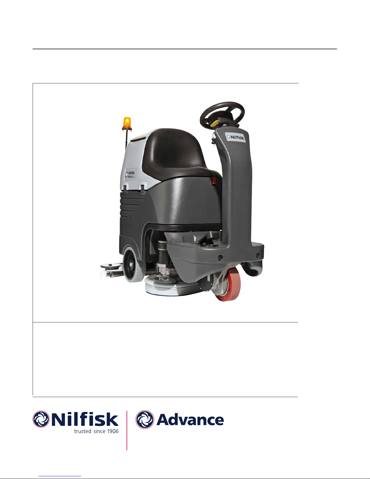
The SC3000 is a “Ride-on” industrial machine designed to wash and dry oors in one pass. The machine is
powered by on-board batteries, models can be equipped with EcoFlex™ system (optional). The machine features variable oor pressure disc or cylindrical brushes, controlled detergent solution dosing and a rear squeegee with rubber blades that vacuums and dries the oor.
Service Manual Purpose and Field of Application
The Service Manual is a technical resource intended to help service technicians when carrying out maintenance and repairs on the SC3000, to guarantee the best cleaning performance and a long working life for the
machine.
Please read this manual carefully before performing any maintenance and repair procedure on the machine.
Other Reference Manuals
5
Model Product Code User Manual Spare Parts List
Nilsk BR 652 9087260020
Nilsk BR 652 - Car 9087261020
Nilsk BR 752 9087262020
Nilsk BR 752 - Car 9087263020
Nilsk BR 752C 9087264020
Nilsk BR 752C - Car 9087265020
Advance SC3000 9087267020 9098827000 9098828000
Assembly Instructions Instruction Code Machines concerned
24V 670W vacuum system motor kit 9098456000 Nilsk BR 652 - BR 752 - BR 752C
EcoFlex™ Kit 9098219000 Advance SC3000
Battery charger kit 9098215000 Nilsk BR 652 - BR 752 - BR 752C
Reverse gear buzzer kit 9098773000 Nilsk BR 652 - BR 752 - BR 752C
9098684000 9098685000
These manuals are available at:
• Local Advance or Nilsk Retailer
• Advance website: www.advance-us.com
• Nilsk website: www.nilsk.com
Page 6

Service Manual – SC3000
General Information
Conventions
Forward, backward, front, rear, left or right are intended with reference to the operator’s position, that is to
say in driving position.
Service and Spare Parts
Service and repairs must be performed only by authorised personnel or Nilsk Service Centers. The authorised
personnel is trained directly at the manufacturer's premises and has original spare parts and accessories.
Contact Nilsk Retailer indicated below for service or to order spare parts and accessories, specifying the machine model and serial number.
(Apply Retailer label here)
6
Serial Number Decal
The machine model and serial number are marked
on the plate (see the example to the side).
Product code and year of production are marked on
the same plate.
This information is useful when requiring machine
spare parts. Use the following table to write down
the machine identication data.
Model: Scrubber-Dryer SC3000 26D EcoFlex
Prod. Nr: 9087267020
GVW: 453 kg/999 lb
63 A
Type E Floor cleaning machine
UL STD 583
CSA STD C22.2 N.68-92
A Nilfisk-Advance Brand
IPX4
Charg.100-240Vac 50-60Hz
Control Nr:
3084826
Serial No: ..................
Date code: .......
LpA = 65 dB(A)
Battery 24 Vdc
2%
“Made in Hungary”
Nilfisk-Advance, Inc.
Plymouth, MN, USA
www.advance-us.com
P100544
MACHINE model .............................................................................................
PRODUCT code ..............................................................................................
MACHINE serial number .................................................................................
Page 7

Service Manual – SC3000
General Information
Safety
The following symbols indicate potentially dangerous situations. Always read this information carefully and
take all necessary precautions to safeguard people and property.
Symbols
Danger! It indicates a dangerous situation with risk of death for the operator.
Warning! It indicates a potential risk of injury for people or damage to objects.
Caution! It indicates a caution related to important or useful functions.
Note: It indicates a remark related to important or useful functions.
7
General Instructions
Specic warnings and cautions to inform about potential damages to people and machine are shown below.
Warning! Make sure to follow the safety precautions to avoid situations that may lead to
serious injuries.
− Before performing any maintenance, repair, cleaning or replacement procedure disconnect the
battery connector and remove the ignition key.
− This machine must be used by properly trained operators only.
− Keep the batteries away from sparks, ames and incandescent material. During the normal op-
eration explosive gases are released.
− Do not wear jewelry when working near electrical components.
− Do not work under the lifted machine without supporting it with safety stands.
− Do not operate the machine near toxic, dangerous, ammable and/or explosive powders, liquids
or vapors: This machine is not suitable for collecting dangerous powders.
− Battery charging produces highly explosive hydrogen gas. Keep the tank assembly open during battery charging and perform this procedure in well-ventilated areas and away from naked
ames.
Page 8

Service Manual – SC3000
Caution! Make sure to follow the safety precautions to avoid situations that may lead to
serious injuries, damages to materials or equipments.
− Carefully read all the instructions before performing any maintenance/repair procedure.
− Before using the battery charger, ensure that frequency and voltage values, indicated on the
machine serial number plate, match the electrical mains voltage.
− Do not pull or carry the machine by the battery charger cable and never use the battery charger
cable as a handle. Do not close a door on the battery charger cable, or pull the battery charger
cable around sharp edges or corners. Do not run the machine on the battery charger cable.
− Keep the battery charger cable away from heated surfaces.
− Do not use the machine if the battery charger cable or plug is damaged. If the machine is not
working as it should, has been damaged, left outdoors or dropped into water, return it to the
Service Center.
− To reduce the risk of re, electric shock, or injury, do not leave the machine unattended when
it is plugged in. Before performing any maintenance procedure, disconnect the battery charger
cable from the electrical mains.
− Do not smoke while charging the batteries.
− To avoid any unauthorized use of the machine, remove the ignition key.
− Do not leave the machine unattended without being sure that it cannot move independently.
− Always protect the machine against the sun, rain and bad weather, both under operation and
inactivity condition. Store the machine indoors, in a dry place: This machine must be used in dry
conditions, it must not be used or kept outdoors in wet conditions.
− Before using the machine, close all doors and/or covers as shown in the User Manual.
− This machine is not intended for use by persons (including children) with reduced physical,
sensory or mental capabilities, or lack of experience and knowledge, unless they have been given
supervision or instruction concerning use of the machine by a person responsible for they safety.
Children should be supervised to ensure that they do not play with the machine.
− Close attention is necessary when the machine is used near children.
− Use only as shown in this Manual. Use only Nilsk’s recommended accessories.
− Take all necessary precautions to prevent hair, jewelry and loose clothes from being caught by
the machine moving parts.
− Do not use the machine on slopes with a gradient exceeding the specications.
− Do not use the machine in particularly dusty areas.
− Use the machine only where a proper lighting is provided.
− If the machine is to be used where there are other people besides the operator, it is necessary to
install the pivoting light and the reverse gear buzzer (optional).
− While using this machine, take care not to cause damage to people or objects.
− Do not bump into shelves or scaffoldings, especially where there is a risk of falling objects.
− Do not put any can containing uids on the machine.
General Information
8
Page 9

Service Manual – SC3000
− The machine working temperature must be between 0 °C and +40 °C.
− The machine storage temperature must be between 0 °C and +40 °C.
− The humidity must be between 30% and 95%.
− When using oor cleaning detergents, follow the instructions on the labels of the detergent
bottles.
− To handle oor cleaning detergents, wear suitable gloves and protections.
− Do not use the machine as a means of transport.
− Do not allow the brushes to operate while the machine is stationary to avoid damaging the oor.
− In case of re, use a powder re extinguisher, not a water one.
− Do not tamper with the machine safety guards and follow the ordinary maintenance instructions
scrupulously.
− Do not allow any object to enter into the openings. Do not use the machine if the openings are
clogged. Always keep the openings free from dust, hairs and any other foreign material which
could reduce the air ow.
− Do not remove or modify the plates afxed to the machine.
− To manually move the machine, the electromagnetic brake must be disengaged. After moving the
machine manually, engage the electromagnetic brake again. Do not use the machine when the
electromagnetic brake handwheel is screwed down.
− When the machine is to be pushed for service reasons (missing or discharged batteries, etc.), the
speed must not exceed 4 km/h.
− This machine cannot be used on roads or public streets.
− Pay attention during machine transportation when temperature is below freezing point. The
water in the recovery tank or in the hoses could freeze and seriously damage the machine.
− Use brushes and pads supplied with the machine and those specied in the User Manual. Using
other brushes or pads could reduce safety.
− In case of machine malfunctions, ensure that these are not due to lack of maintenance. Otherwise, request assistance from the authorised personnel or from an authorised Service Center.
− If parts must be replaced, require ORIGINAL spare parts from an Authorised Dealer or Retailer.
− To ensure machine proper and safe operation, the scheduled maintenance shown in the relevant
chapter of this Manual, must be performed by the authorised personnel or by an authorised Service Center.
− Do not wash the machine with direct or pressurised water jets, or with corrosive substances.
− When WET batteries are installed on the machine, do not tilt the machine for more than 30°
from the horizontal plane to prevent the highly corrosive acid from leaking out of the batteries. If
the machine must be tilted to perform any maintenance procedure, remove the batteries.
− The machine must be disposed of properly, because of the presence of toxic-harmful materials (batteries, etc.), which are subject to standards that require disposal in special centres (see
Scrapping chapter).
General Information
9
Page 10

Service Manual – SC3000
Machine Lifting
Warning! Do not work under the lifted machine without supporting it with safety stands.
Machine Transportation
Warning! Before transporting the machine, make sure that:
All covers are closed.
The ignition key is removed.
The machine is securely fastened to the means of transport.
General Information
10
Page 11

Service Manual – SC3000
Machine Nomenclature (know your machine)
Squeegee hook
Seat
Battery connector
Emergency push-button
Recovery
tank cover
Dumping recovery
tank assembly
General Information
Steering wheel with
control panel
Steering wheel
height control lever
Ignition key
11
Battery
charger
Solution/clean
water tank
opening/closing
valve
Squeegee
blades assembly
Solenoid valve
Solution filter
Brush/pad-holder deck
Bumper wheel
height adjustment
Heel support
Electromagnetic
brake unlocking lever
Drive pedal
Front steering,
driving and
braking wheel
P100370
Page 12

Service Manual – SC3000
Detergent tank
Machine Nomenclature (continued)
Vacuum grid with
automatic shut-off float
Container with
Rating plate
debris collection grid
Battery charger cable
Electronic component
compartment cover
Lifted tank assembly
and driver's seat
Tank assembly stand
Vacuum system motor filter
Vacuum system motor
General Information
Battery connection
diagram
12
Cylindrical brush
deck side skirt
Cylindrical
brush deck
Solution/clean
water draining valve
Squeegee balance
adjusting handwheel
Recovery water drain hose
Solution/clean
water draining adapter
Solution/clean water
tank filler plug with removable filler hose
Solution/clean water tank
Squeegee vacuum hose
Squeegee bumper wheels
Squeegee mounting handwheels
Squeegee support wheels
Squeegee
24V
Front
Batteries
Battery caps
P100359
Page 13
Service Manual – SC3000
Battery lights
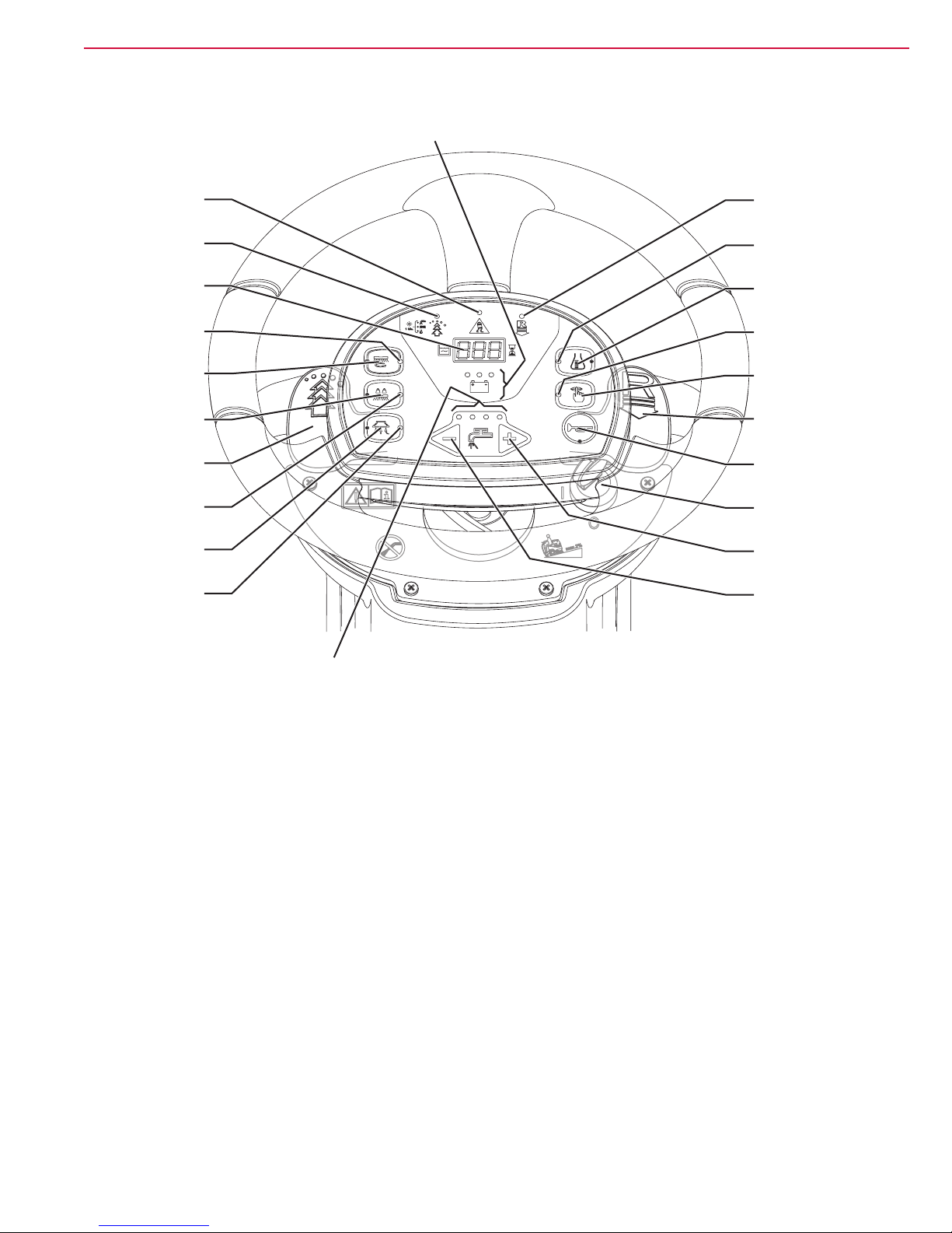
Control Panel
General Information
13
Anti-skid control
activation
led indicator
EcoFlex™ system
led indicator
Hour counter and
solution level display
Scrub On/Off
led indicator
Scrub On/Off
push button
Extra pressure
push button
EcoFlex™
lever
Extra pressure
led indicator
Vacuum system
push button
Vacuum system
led indicator
Reverse gear
led indicator
Washing detergent
flow control
led indicator
Detergent flow
control push button
Mute function
led indicator
Mute function
push button
Reverse gear
lever
Horn push button
Ignition key
Solution flow
increase
push button
Solution flow
decrease
push button
Solution flow indicator
P100372
Page 14
Service Manual – SC3000
General Information
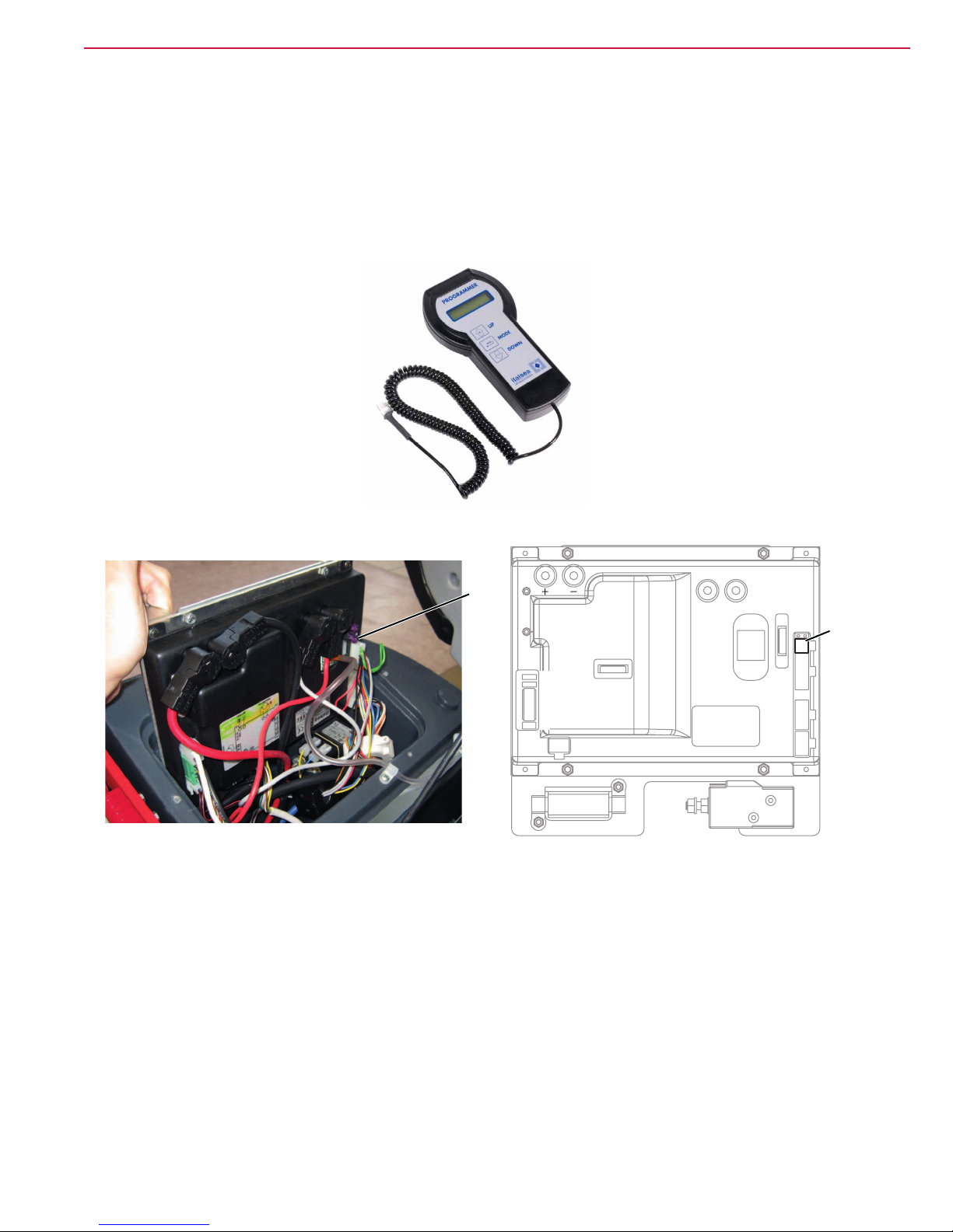
Service and Diagnostic Equipment
Besides a complete set of standard meters, the following instruments are necessary to perform fast checks and
repairs on Nilsk-Advance machines:
• Laptop computer charged with the current version of EzParts, Adobe Reader and (if possible) Internet
connection
• Digital Volt Meter (DVM)
• Amperometric pliers with possibility of making DC measurements
• Hydrometer
• Battery charge tester to check 12V batteries
• Static control wrist strap
• Dynamometric wrench set
• A copy of the User Manual and Spare Parts List of the machine to be serviced (provided with the machine
or available at www.advance-us.com or other Nilsk-Advance websites).
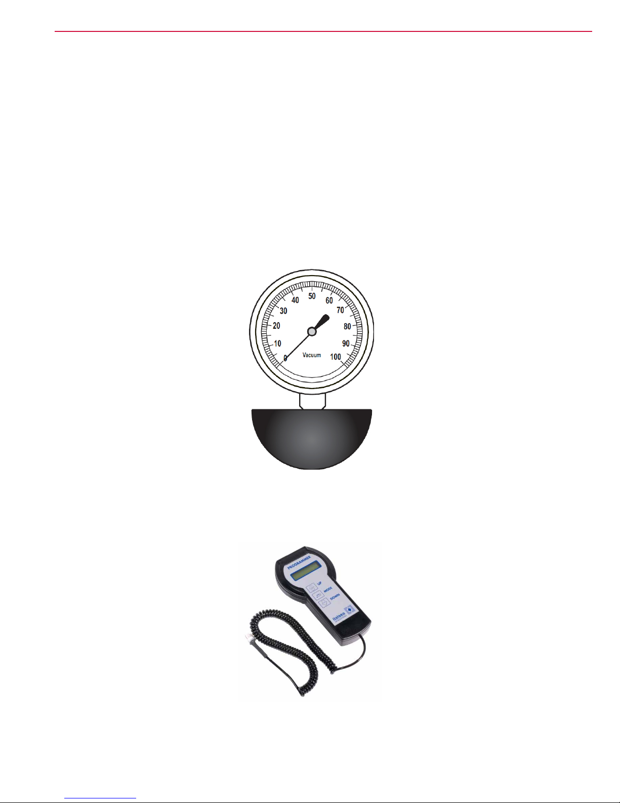
The following equipment is also available at Nilsk-Advance Centers:
• Vacuum water lift gauge, P/N 56205281
14
• Italsea universal programmer, P/N 9097297000
Page 15

Service Manual – SC3000
General Information
Technical Data
General technical data
Description
Cleaning width 26 in (660 mm) 30 in (710 mm) 30 in (710 mm)
Squeegee width 35 in (890 mm)
Solution/clean water tank capacity 21 US gal (80 L)
Solution ow 0.26 ÷ 0.8 US gal/min. (1 ÷ 3 L/min.)
Recovery tank capacity 21 US gal (80 L)
Minimum/maximum solution ow (with and without EcoFlex™
system)
EcoFlex™ kit tank capacity 1.3 US gal (5 L)
EcoFlex™ kit detergent ow setting Ratio 1:400 ÷ 1:33 (0.25% ÷ 3%)
Rear wheel diameter 9.8 in (250 mm)
Front wheel specic pressure on the oor (*) 72 psi (0.5 N/mm2)
Rear wheel specic pressure on the oor (*) 130 psi (0.9 N/mm2)
Front steering, driving and braking wheel diameter 8.8 in (225 mm)
Vacuum system motor power 0.56 hp (420 W)
Drive system motor power 0.4 hp (300 W)
Maximum speed 3.7 mi/h (6 km/h)
Maximum gradient when working 2% (1.14°)
Sound pressure level at workstation
(ISO 11201, ISO 4871, EN 60335-2-72) (LpA)
Machine sound pressure level
(ISO 3744, ISO 4871, EN 60335-2-72) (LwA)
Vibration level at the operator's arms
(ISO 5349-1, EN 60335-2-72)
Vibration level at the operator's body
(ISO 2631-1, EN 60335-2-72)
Battery compartment size (length x width x height) 14.9 x 21.2 x 11.8 in (380 x 540 x 300 mm)
Battery type
Standard batteries autonomy 2.5 - 3.5 hours
Total electrical input 60 A
Machine height 46.8 in (1,190 mm)
Machine maximum length 53.5 in (1,360 mm)
Machine width without squeegee 26.4 in (670 mm) 29.4 in (748 mm) 31.9 in (810 mm)
Vacuum performance 0.0098 MPa (1,000 mmH2O)
Nilsk BR 652
Advance SC3000
4 6V batteries, 180 Ah C5 (GEL/AGM)
Nilsk BR 752 Nilsk BR 752C
0 ÷ 0.8 US gal/min. (0 ÷ 3 L/min.)
65 dB(A) ± 3 dB(A)
82 dB(A)
< 98.4 in/s2 (< 2.5 m/s2)
3.1 in/s2 (0.8 m/s2)
4 6V batteries, 180 Ah C5 (WET)
15
(*) Machines have been tested under the following conditions:
◦ With operator on board (165.3 lb - 75 kg)
◦ Maximum battery size
◦ Maximum brush and squeegee size
◦ Full clean water tank
◦ Optional components installed
◦ Weight on wheels checked
◦ Print on the oor checked on cement for each single wheel
◦ Result expressed as maximum value for front and rear wheels
Page 16

Service Manual – SC3000
General Information
Technical Data (continued)
Technical data for machines with disc deck
Description
Brush/pad diameter 13 in (330 mm) 355 mm
Weight without batteries and with empty tanks 385.8 lb (175 kg) 177 kg
Maximum weight with batteries, full tanks and operator
(GVW)
Hourly efciency (4 km/h) ~ 24,488 ft2 (~ 2,275 m2) ~ 2,500 m
Deck right/left offset (variable)
Brush distance from the oor (when lifted) 1.9 in (48 mm) 48 mm
Brush/pad-holder motor power 2 x 0.53 hp (2 x 400 W)
Brush/pad-holder speed 230 rpm
Brush/pad-holder pressure with extra-pressure function
turned off
Brush/pad-holder pressure with extra-pressure function
turned on
Technical data for machines with cylindrical brush deck
Description Nilsk BR 752C
Cylindrical brush size (diameter x length) 5.7 x 27.2 in (145 x 690 mm)
Weight without batteries and with empty tanks 396.8 lb (180 kg)
Maximum weight with batteries, full tanks and operator
(GVW)
Hourly efciency (4 km/h) ~ 26910 ft2 (~ 2,500 m2)
Deck right/left offset 3.5 / 3.5 in (90 / 90 mm)
Cylindrical brush deck distance from the oor (when
lifted)
Cylindrical brush motor power 2 x 0.8 hp (2 x 600 W)
Cylindrical brush speed 720 rpm
Cylindrical brush pressure 77.1 lb (35 kg)
Nilsk BR 652
Advance SC3000
983.2 lb (446 kg) 448 kg
0 ÷ 3.9 in / 1 ÷ 0 in
(0 ÷ 100 mm / 25 ÷ 0 mm)
66.1 lb (30 kg) 32 kg
105.8 lb (48 kg) 50 kg
994.3 lb (451 kg)
0.8 in (22 mm)
15 / 150 mm - 105 / 0 mm
Nilsk BR 752
16
2
Page 17

Service Manual – SC3000
Dimensions
Nilsk BR 652 - Advance SC3000
General Information
1190 mm (46.85 in)
890 mm (35 in)1360 mm (53.5 in)
17
Nilsk BR 752
P100367
1190 mm (46.85 in)
890 mm (35 in)1360 mm (53.5 in)
P100368
Page 18

Service Manual – SC3000
Dimensions (continued)
Nilsk BR 752C
General Information
1190 mm (46.85 in)
890 mm (35 in)1360 mm (53.5 in)
18
P100369
Page 19
Service Manual – SC3000
General Information
Maintenance
The lifespan of the machine and its maximum operating safety are ensured by correct and regular maintenance.
Warning! Read carefully the instructions in the Safety chapter before performing any
maintenance procedure.
The following tables provides the scheduled maintenance. The intervals shown may vary according to particular working conditions, which are to be dened by the person in charge of the maintenance.
For instructions on maintenance procedures, see the following paragraphs.
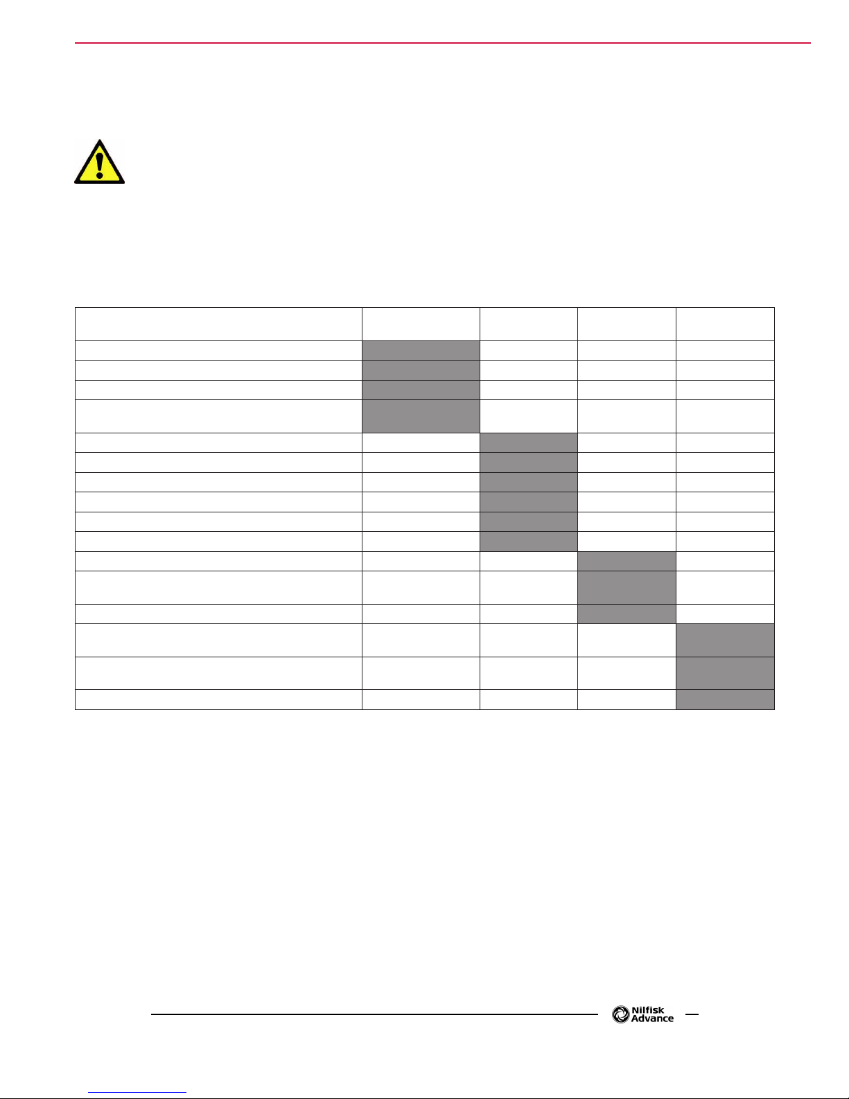
Scheduled Maintenance Table
Procedure
Battery charging
Squeegee cleaning
Brush/cylindrical brush cleaning
Tank, debris collection grid and vacuum grid with oat
cleaning, and cover gasket check
EcoFlex™ system cleaning and draining (optional)
Squeegee blade check and replacement
Side skirt check (only for BR 752C)
Solution lter cleaning
Vacuum system motor lter cleaning
Battery (WET) uid level check
Screw and nut tightening check (1)
Check and adjustment of driving belts between motors
and cylindrical brushes (only for BR 752C)
Electromagnetic brake efciency check
Brush/pad-holder motor carbon brush check or
replacement
Vacuum system motor carbon brush check or
replacement
Drive system motor carbon brush check or replacement
Daily, after using
the machine
Weekly
Every six
months
Yearly
19
(1) And after the rst 8 working hours.
Page 20
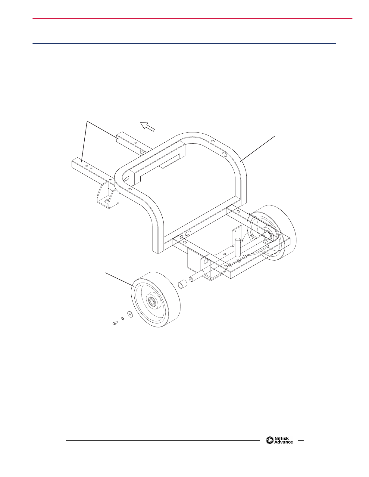
Chassis System
Front
1
Frame (main parts)
1. Steering assembly plate holder
2. Tanks and driver's seat holder
3. Rear wheels on xed axle
Chassis System 20Service Manual – SC3000
2
3
P100545
Page 21
Control System 21Service Manual – SC3000
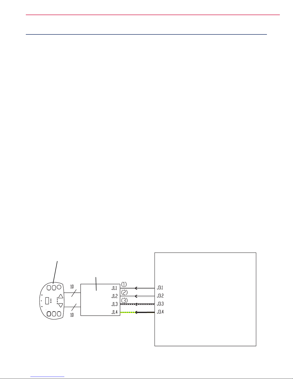
Control System
Functional Description
The architecture of the electronic system controlling the electrical machine utilities consists of a main electronic board (EB1), and a display electronic board (EB2) which is connected to the dashboard (EB3) - the main
user interface.
The main electronic board (EB1) manages all the utilities.
It drives directly the following accessories:
− Drive system motor with electromagnetic parking brake
− Vacuum system motor
− Deck actuator
− Squeegee actuator
− Solution ow solenoid valve
− Detergent pump
− Buzzer
It drives the brush deck motors by means of the electromagnetic switch.
The display electronic board (EB2) manages all the input signals (push-buttons) and the output signals (LED)
from keyboard (EB3) to which it is connected by 2 at cables.
There is also a 3-gure display on the display electronic board (EB2), which is mainly used to display the hour
counter, the solution tank level, and for any alarms (see below). There are also 2 microswitches activated by
the levers under the steering wheel.
The display electronic board (EB2) sends all the input and output signals of these components to the main
electronic board (EB1) using 2-wire 2-way serial communications protocol.
The system also has an on-board battery charger which also communicates with the main electronic board
(EB1) using propriety serial protocol, so the operator can see the operating state (charging phase) on the same
user interface of the dashboard (EB3).
Wiring Diagram
Dashboard instrument electronic board (EB3)
Function electronic board (EB1)
Display electronic board (EB2)
Dashboard power supply +
Dashboard serial +
Dashboard serial -
Dashboard power supply -
P100546
Page 22

Component Location
• Function electronic board (EB1)
• Control panel electronic board (EB2)
• Dashboard (EB3)
Control System 22Service Manual – SC3000
Function electronic
1
board (EB1)
Control panel elec-
2
tronic board (EB2)
Dashboard (EB3)
3
P100547
P100548
Page 23

Control System 23Service Manual – SC3000
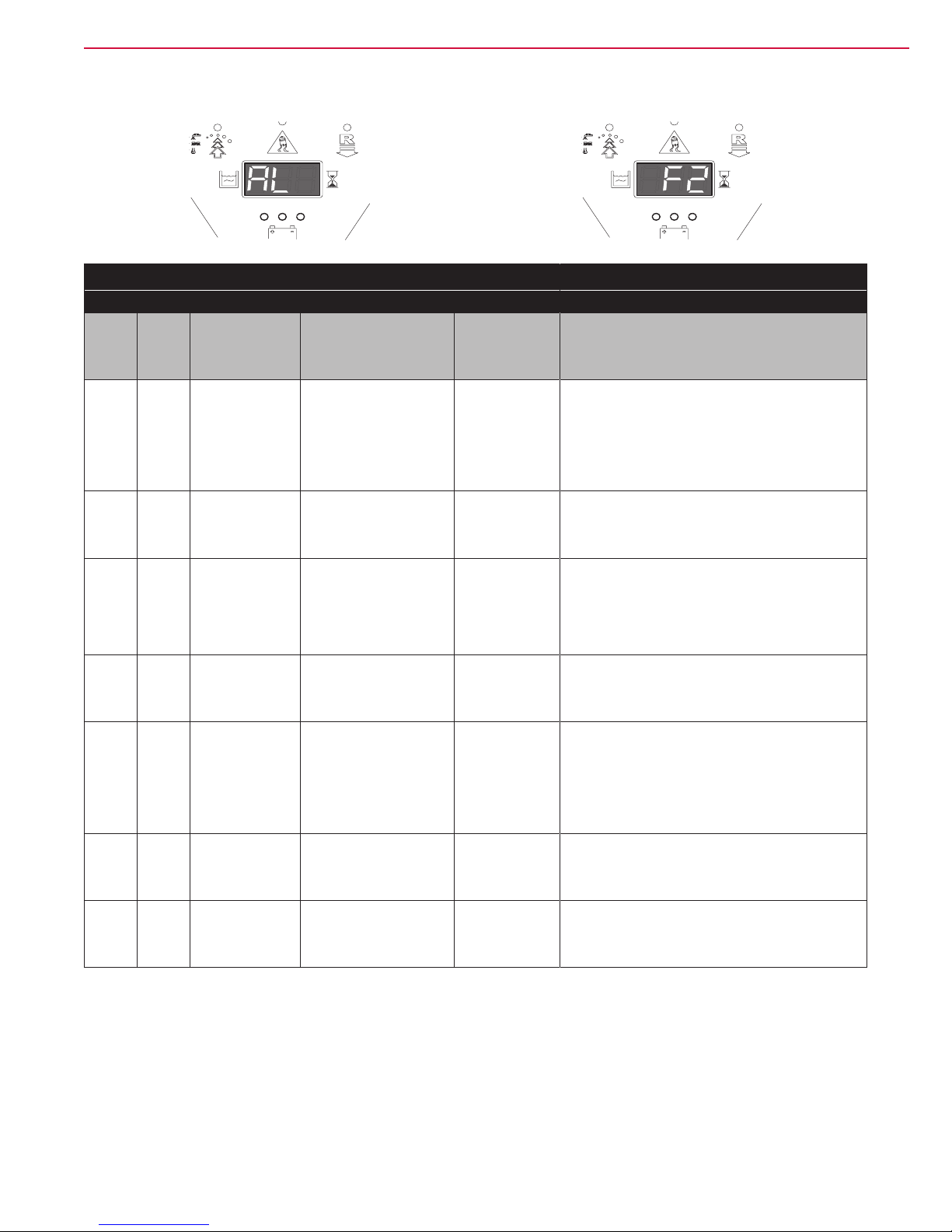
Function Electronic Board Alarm Codes
The function electronic board indicates a series of alarms in case of malfunction of one or more systems, and
in case of abnormal conditions detected in the input signals.
The alarms are shown on the display (except “F6”) by 2 signs following each other:
“AL” and “G2”, where G2 is one of the alarm codes (see the descriptions in the following tables).
P100549 P100550
Also, the alarms are repeated (in case of display malfunction) by the diagnostic LEDs (yellow and red) on the
electronic board, as described in the following tables.
General alarms
Alarm on the function electronic board - YELLOW LED + RED LED FLASHING
Alarm
Code
on the
display
No. of
ashes
on the
board
G2 2 EEPROM error. EEPROM error. Function block
G3 3 General thermal
Meaning Condition Effect
+ Default setting
reset.
protection.
The heatsink of the board
reached a temperature
up to 194 °F (90 °C).
Function block.
A
P100401A
Troubleshooting action
If the machine is normally working after the G2 message appearing, it could be caused by an electromagnetic spike from the environment that didn’t damage
the system.
1. Check all the parameter (see page 32 - 33)
settings (battery type, parameters etc.) because
of they could be restored to default.
1. Check the current ow in the drive motor (it has
to be 6-8amps without load and it has to remain
below 20 amps during operations).
2. Check the current ow in the vacuum motor (it
has to be less than 20 amps).
3. Verify the correct thermal dissipation of the board:
the correct installation on the metal bracket,
obstacles to the air ow from the bottom (deck
area) to the extraction hole on the top cover of the
electric box.
4. If all is ok, it could be generated by extreme
working conditions like room temperature >30°C,
slopes in the working path. The machine has
to be maintained off in order to restore the right
temperature into the board and then it could be
used.
Page 24

General alarms
Alarm on the function electronic board - YELLOW LED + RED LED FLASHING
Alarm
Code
on the
display
No. of
ashes
on the
board
G4 4 Blown F2 fuse. Blown F2 fuse. Function block.
G5 5 Wrong KEY
G6 6 No signal from
G7 7 Undervoltage. The battery voltage
G8 8 Serial
G9 9 Battery voltage
Meaning Condition Effect
sequence.
BATTERY
CHARGER
communication
error with
dashboard
electronic board.
drop.
Voltage dip (of the order
of 100ms or less) of the
key input.
No signal from battery
charger on the
communication yellow
wire to pin 11 of J1
connector
stay for more than 10
senconds lower than
18,4 Volt (for WET
batteries, 19,6 Volt for
GEL-AGM batteries).
No signal or
decoding error in the
communication between
the function Electronic
board (EB1) and the
display board (EB2).
Battery voltage drop
bigger than 3 Volt in less
than 1 sencond.
Function block.
The charging
battery phase is
not shown
Function block.
No block.
Drive system +
electromagnetic
brake block.
Control System 24Service Manual – SC3000
Troubleshooting action
F2 fuse is a power safety fuse (100 amps rated)
and its primary function is to avoid that a short drive
so much current to generate smoke or re into the
board. The F2 opening is normally due to a severe
damage of the board.
1. Open the board plastic cover to verify the
condition of the board.
2. If everythink seems ok try to substitute F2 fuse
otherwise substitute the board.
3. Take care to properly tight the fuse .
1. Check any bad contact in the key switch.
2. Check for any bad contact in the wires from the
key switch to the pin 5 and 6 of J3 connector on
the board.
3. If necessary substitute the key switch.
1. Check the continuity of the yellow wire from the 3
way charger connector to pin 11 of J1 connector.
2. If ok, it is necessary to substitute the charger or
the board.
1. Check the battery voltage without and with load. If
necessary substitute the bad batteries.
2. Charge the batteries with a complete charging
cycle.
1. Check the 4 wires from the 4 ways connector on
the dashboard to the pin 1,2,3,4 of J3.
2. If ok substitute the dashboard.
G9 tipically shows that the red safety button under
the seat (that mechanically open the ANDERSON
CONNECTOR) was pressed during the machine
operation.
If this is not the case, check the power wirings from
the batteries to the ANDERSON connector: it could
be a bad contact in one of these power connections.
Otherwise it could be caused by one or more batteries damaged or to be replaced.
Page 25
Function Electronic Board Alarm Codes (continued)
P100549 P100551
Function electronic board alarms
Alarm on the function electronic board - RED LED FLASHING
Alarm
Code
on the
display
No. of
ashes
on the
board
F2 2 BRUSH motor
F3 3 VACUUM
F4 4 DECK
F5 5 VACUUM
F6 6 PRESSURE
F7 7 VACUUM
F8 8 Function general
Meaning Condition Effect
amperometric
protection.
SYSTEM
amperometric
protection
ACTUATOR
position
irregularity.
SYSTEM power
section damage.
SWITCH signal
fault.
SYSTEM output
short circuit.
relay fault.
The voltage drop
measured on the F1
fuse is higher than the
value of the parameter
(see page 32 - 33) VS1
(for disc deck, VS2 for
cylindrical deck).
The current draw in the
vacuum motor is higher
than 30 Amp for more
than 10 senconds.
End-of-stroke
microswitch conguration
not plausible or endof-stroke microswitch
not reached within 10
senconds.
Internal board mosfet
short circuit.
Pressure switch input
higher than 4.0 Volt.
The inrush current draw
in the vacuum motor is
higher than 100 amps.
The main relays inside
the board is stuck
(always closed or always
open).
Brush
electromagnetic
switch output
block.
Vacuum system
block
Deck actuator
block.
Vacuum system
block.
Water level
visualization
missing +
water ow and
% detergent
management
fault.
Vacuum system
block.
Function block.
Troubleshooting action
1. Check the current ow in the brush motors (the
sum of the 2 motors has to be under 50 amps on
disc decks, under 70 amps on cylindric decks).
2. If the current is ok check the correct tight of the
F1 fuse nuts (F1 fuse is on the bracket under the
function board).
1. Check for any debris into the vacuum motor
2. Check that the vacuum motor fan is free to rotate
(bearing stuck ?).
3. If necessary substitute the vacuum motor.
1. Check the deck actuator wire and its connection
to the 6 way J4 connector on the board.
2. Check for any obstacle or excessive friction that
don’t allow the actuator to move.
3. If necessary substitute the actuator.
1. Check any short in the vacuum motor wiring.
2. Check the vacuum motor operation (try to power
it directly).
3. Substitute the board.
1. Check for the correct positioning of the pressure
gauge module into the board: take care of the 2
side connectors that have to be tted in properly.
2. If the connection is ok, substitute ALL THE
pressure gauge KIT.
1. Check any short in the vacuum motor wiring.
2. Check the vacuum motor operation (try to power
it directly).
3. Substitute the vacuum motor.
Substitute the board.
Control System 25Service Manual – SC3000
All “general” and “function” alarms, and their relevant effects remain until reset from KEY input. In case of
simultaneous errors, the one with greater priority is shown rst (priority order is opposite to the number of
ashes).
Page 26
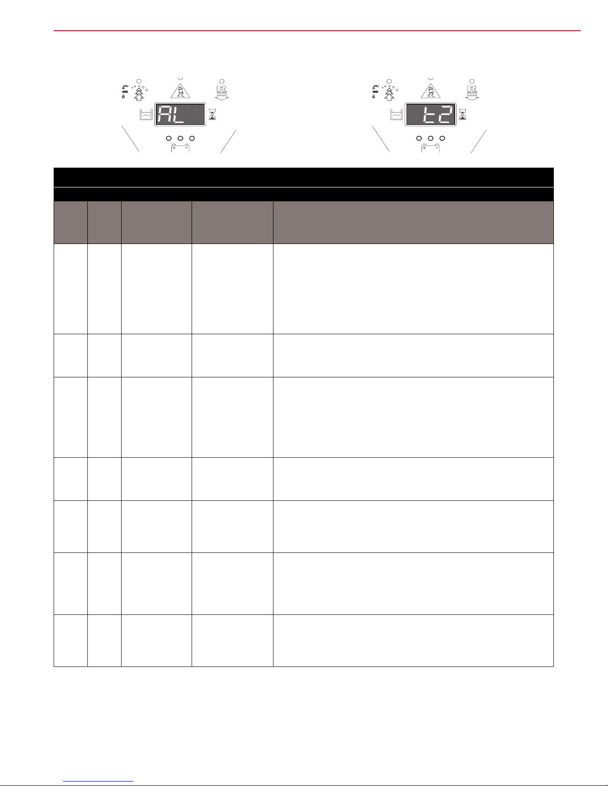
Function Electronic Board Alarm Codes (continued)
P100549 P100552
Drive system alarms
Alarm on the function electronic board - YELLOW LED FLASHING
Alarm
Code
on the
display
No. of
ashes
on the
board
t2 2 Amperometric
t3 3 Electromagnetic
t4 4 Pedal input
t5 5 Drive system
t6 6 Pedal input not
t7 7 Overcurrent
t8 8 Drive system
Meaning Condition
protection
intervention.
brake not present
activated by
ignition.
power section
damage.
admitted.
(motor D.C.).
relay fault.
Current draw in
to the drive motor
higher than the
parameter (see
page 32 - 33)
“INOM“ for more
than parameter
(see page 32 - 33)
“TMAX“ time.
Open circuit
between J5.1 and
J5.2
Pedal output on
J3.8 higher than
the parameter
(see page 32 - 33)
“DEADL” when
the machine was
switched on by the
key.
Internal board
mosfet short circuit.
Open circuit
between J3.7 and
J3.9 or pedal output
on J3.8 higher than
5 Volt.
Drive motor current
higher than 1.5
times the value
of the parameter
(see page 32 - 33)
“IMAX”.
The Drive system
relays inside the
board is stuck
(always closed or
always open).
Troubleshooting action
Check the drive motor current draw: it has to be 6-8 amps without load and it
has to remain under 20 amps during operation.
1. Check the continuity of the 2 wires of the electrobrake of the motorwheel
up to the 2 way connector J5 on the board.
2. Check for the electrobrake impedance: has to be about 40 Ohms.
3. If necessary substitute the electrobrake.
1. Check that the pedal returns into its released position when not pressed.
2. If necessary substitute the pedal.
1. Check any short in the main motorwheel wires.
2. Try to disconnect the 2 Ø6 mm fast connectors M1 and M2 from the
board, switch on the machine and press the pedal.
3. If the alarm still appears, substitute the board.
Check the wiring from the pedal and the J3 connector pins 7, 8, 9.
From the battery – you have to measure:
- About 5 Volt on pin 7.
- From 0.7 to 4.5 Volt on pin 8 (it has to change moving the pedal).
- About 0 – 0.7 Volt on pin 9.
1. Check any short in the main motorwheel wires.
2. Check the impedance of the motorwheel motor: it has to be about 0.6 –
0.8 Ohms.
3. If necessary substitute the motorwheel motor.
Substitute the board.
Control System 26Service Manual – SC3000
All the drive system alarms activates to cut off the power supply to the driving wheel motor (not to the ELECTROMAGNETIC BRAKE), until reset from KEY input [except alarm t4 which is reset as soon as J3.8 voltage
(drive pedal output) became less then the value of the parameter “DEADL” (see table “Function electronic
board parameters” page 32 - 33). In case of simultaneous errors, the one with greater priority is shown rst
(priority order is opposite to the number of ashes).
Page 27

Function Electronic Board Alarm Codes (continued)
Other alarm indications on the display
Alarm Code
on the
display
“---” Water level signal missing or not as specied. Pressure switch module output higher than 4.0 Volt.
Meaning Condition
Control System 27Service Manual – SC3000
“888”
Off Dashboard electronic board power supply missing. Voltage between J1.1 and J1.4 less than 12 Volt.
Serial communication problem between dashboard electronic
board and function electronic board.
Signal missing or errors.
Black-box: Record of Alarms, Battery Management Parameters (see page 32
- 33), Partial Hour Counter
The data indicated in the following table (ALARMS, BATTERY MANAGEMENT DATA) are stored in the nonvolatile memory of the electronic board and can be recalled and displayed by the external programmer (ITALSEA UNIVERSAL PROGRAMMER, NILFISK P/N 9097297000) connect to port J9. For each stored datum
(event) the value HOURS.MINUTES of the TOTAL hour counter is associated when the alarm occurred. The
last 20 events are stored. When the total number of events is used up, the next events overwrite the older ones.
The data are shown on the programmer display, listed by decreasing order (starting from the latest) as: DATUM - HOUR (1 per page). The UP and DOWN buttons are used to select 1 page at a time. All the stored paged
can be scrolled. The “info” button shows the DATUM - EVENT DESCRIPTION for the selected line.
DATUM EVENT DESCRIPTION Condition
G2 EEPROM error See alarm code description
G3 General thermal protection See alarm code description
G4 Blown F2 fuse See alarm code description
G5 Wrong KEY sequence See alarm code description
G6 No signal from BATTERY CHARGER See alarm code description
G7 Battery undervoltage See alarm code description
G8
G9 Battery voltage drop See alarm code description
F2 Brush motor protection intervention See alarm code description
F3 VACUUM SYSTEM overcurrent See alarm code description
F4 DECK ACTUATOR position irregularity See alarm code description
F5 VACUUM SYSTEM power section damage See alarm code description
F6 PRESSURE SWITCH signal fault See alarm code description
F7 VACUUM SYSTEM output short circuit See alarm code description
F8 Function general relay fault See alarm code description
t2 Drive system amperometric protection intervention See alarm code description
t3 Electromagnetic brake not present See alarm code description
t5 Drive system power section damage See alarm code description
t6 Pedal input not admitted See alarm code description
t7 Drive system overcurrent See alarm code description
t8 Drive system relay fault See alarm code description
GB-N Time of continuous use with discharged batteries
GC Charging cycle interrupted before completion
GD-N Charging phase duration
Serial communication error with dashboard electronic
board
See alarm code description
“N” is the number of hours from the key switching ON and OFF
during the battery level is under 18,4 Volt for WET, 19,6 for
AGM. This event is not recorded if the above time is less than 10
minutes.
Battery charger disconnection before PHASE IV (= with red or
yellow LED on)
N = Number of hours from battery charger connection to
completion of PHASE II (red LED on) if < 4
Page 28

Control System 28Service Manual – SC3000
Last stored event
Machine working hours
Black-box: Record of Alarms, Battery Management Parameters (see page 32
- 33), Partial Hour Counter (continued)
Example 1:
Last stored alarm: alarm G8 occurred when the machine working hours were 24h and 19m, next to last stored
alarm: alarm F4 occurred when the machine working hours were 22h and 5m.
PROGRAMMER
Logged alarm-1:
ALL_G8: 24h,19m
Example 2:
Charging cycle interrupted before completion when the machine working hours were 15h and 45m (last stored
event).
PROGRAMMERPROGRAMMER
Logged alarm-2:
ALL_F4: 22h,55m
P100399
PROGRAMMER
GC (-1) 15h,45m
21hours, 31 min
Charging cycle time when interrupted
P100400
Page 29
Control System 29Service Manual – SC3000
Display of Current Values of Signicant Variables, Hour Counters and
Stored Alarms
1. Turn the ignition switch to “0”.
2. Open the electrical component compartment.
3. Connect the ITALSEA programmer, NILFISK P/N 9097297000 to the function electronic board
connector J9 (A).
A
M2
M1
VAVA+
J6
J5
J4
4. Turn the ignition switch to “I”.
5. Scroll with the UP and DOWN buttons the pages in the order shown in the table below.
J7A
J7B
J8
J9
J1
J3
J2
A
P100401
Page 30

Control System 30Service Manual – SC3000
Display of Current Values of Signicant Variables, Hour Counters and
Stored Alarms (continued)
Variable description Value meaning
Software Release Software version loaded on the electronic board
Supply Voltage Battery voltage (V)
Ref. Voltage Drive pedal input voltage (V)
Drive Motor Voltage Drive system motor output voltage (V)
Drive Motor Current Drive system motor current (A)
Brushes Current Brush deck motor current (mV) (*)
Vacuum Current Vacuum system motor current (A)
Heatsink Temp. Temperature detected on the electronic board heatsink (°C)
Hour counter: total TOTAL HOUR COUNTER (h.min)
Hour counter: drive system DRIVE SYSTEM HOUR COUNTER (h.min)
Hour counter: brushes BRUSH HOUR COUNTER (h.min)
Hour counter: vacuum VACUUM SYSTEM HOUR COUNTER (h.min)
Logged Alarm-N ALARM STORAGE (possible) (**)
(*) The value is the same as the voltage drop on the F1 fuse, which is proportional to the current but does not
have the same value in Amp.
(**) See BLACK-BOX paragraph
Page 31

Control System 31Service Manual – SC3000
Display and Change of Parameters Which can be Set by the Technician
The stored value of each parameter shown in the following table could be modied by the Service Operator
from its Default value to another in the range dened from “Min. value” to “Max. value”.
The default value should be ok for most of the applications, however it could be useful to change a parameter
value in order to:
– Customize the machine behavior to particular customer needing (like Maximum speed in forward
(FVM), max speed in reverse (RVM), maximum and minimum pre-set working speeds (WSMIN and
SWMAX if present), reaction time to the pedal pressure variation (AR and DR), time of the ECOFLEX
temporary function (SPT), etc..
– Adapt the board tolerance to partcular devices that are a little bit out of their normal tolerances (ex.
voltage of the pedal output when released (DEADL), voltage when the pedal is fully pressed (DEADH).
– Adapt the board output power limits to protect the motors in particular heavy duty applications (like
Max. current in the deck motors (VS1 for disc, VS2 for cylindrical), max continous current in the drive
motorwheel (INOM) etc.)
1. Turn the ignition switch to “0”.
2. Open the electrical component compartment.
3. Connect the programmer to the function electronic board connector J9 (see gure).
4. Turn the ignition switch to “I”.
5. Press the MODE button.
6. Scroll the parameters with the UP and DOWN buttons to nd the one to be changed.
7. Press the MODE button to enter the “change” mode (the parameter starts to ash).
8. Change the value with the UP and DOWN buttons.
9. Store the new set value by pressing the MODE button.
Page 32

Function Electronic Board Parameters
Parameters which can be set through programming port J9
Code Description
VRID
VS1
VS2
DT
SPT SPOT function timer (s) 5 60 300
DEADL Drive pedal bottom dead area (V) 0.0 0.9 1.5
DEADH Drive pedal top dead area (V) 0.0 2.2 2.5
FVM0 Maximum forward speed (%) 10 100 100
Vacuum system partial supply
voltage (V)
Brush motor protection threshold 1
(mV)
Brush motor protection threshold 2
(mV)
Deck actuator m1 microswitch delay
(ms)
Min.
values
10 16 20
30 50 90
30 60 90
0 0 10
Default
values *
Max.
values
Control System 32Service Manual – SC3000
Meaning
It is the voltage supplied to the vacuum motor when
the SILENCE MODE is active: it could be reduced
to reduce further the noise or increased to increase
the vacuum performances.
It is the max current that is possible to supply to the
disc brush deck.
PAY ATTENTION: increasing this value you will
take more overheating risk on the motors.
It is the max current that is possible to supply to the
cylindrical brush deck.
PAY ATTENTION: increasing this value you will
take more overheating risk on the motors.
Engineering parameter to bias the deck actuator
normal working position.
– Do not modify.
Time of the ECOFLEX temporary function
(ECOFLEX lever / button) after that the normal
settings will be restored.
Pedal output voltage when the pedal is in its
released position.
Pedal output voltage when the pedal is fully
pressed.
Max forward speed.
RVM0 Maximum reverse speed (%) 10 70 100
AR Maximum acceleration ramp (s) 0.5 3.0 5.0
DR Maximum deceleration ramp (s) 0.5 1.0 5.0
Maximum deceleration ramp on
IR
BRK
INOM
reversal (s)
Electromagnetic brake activation
delay (s)
Drive system rated current (A)
Up to machine SN: 3510133204430
Drive system rated current (A)
Starting m. SN: 3510133204431
0.5 0.5 5.0
0.5 1.0 5.0
10 20 30
10 25 30
Max reverse speed.
Time to reach the max forward speed from the
stopped position. Increase to have a slower
reactive drive behavior, decrease to have a more
reactive drive behavior.
Time to reach the machine stopped from the max
speed. Increase to have a slower reactive drive
behavior, decrease to have a more reactive drive
behavior.
PAY ATTENTION: increasing this value would
make the braking spaces longer.
Time to reach the machine stopped from the max
speed, when the gear is reversed. Increase to have
a slower reactive drive behavior, decrease to have
a more reactive drive behavior.
PAY ATTENTION: increasing this value would
make the braking spaces longer.
Delay to the parking brake activation after the
machine is stopped. Decrease to allow the machine
parking in a slope
NOTE: that this machine is not designed to
operate on slopes, so in any case advise the
customer about that.
It is the max continous current that is possible to
supply to the drive motorwheel.
PAY ATTENTION: increasing this value you will
take more overheating risk on the motor.
Page 33

Parameters which can be set through programming port J9
Code Description
IMAX Drive system maximum current (A) 10 80 100
Protection intervention time for IMAX
(s)
TMAX
AMAX Maximum lateral acceleration (g/100) 1 15 100
KG Lateral acceleration control constant 1.0 1.6 2.0
WSMIN (Not used) - -
Up to machine SN: 3510133204430
Protection intervention time for IMAX
(s)
Starting m. SN: 3510133204431
Min.
values
0 15 60
0 20 60
Default
values *
Max.
values
Control System 33Service Manual – SC3000
Meaning
It is the max istantaneous current that is possible to
supply to the drive motorwheel.
PAY ATTENTION: increasing this value you will
take more overheating risk on the motor
It is the time reaction of the drive motorwheel
overloading protection: this parameter is used in
combination with IMAX to have the right response
time curve of the drive motor overloading protection
system.
PAY ATTENTION: increasing this value you will
take more overheating risk on the motor
It is the max side acceleration allowed to the
machine. Over this value the drive system will cut
the power to the motorwheel in order to mantain the
machine stability.
PAY ATTENTION: increasing this value you will
take more tipping risks
Engineering parameter related to AMAX.
- Do not modify.
(available only on other models).
WSMAX (Not used) - -
(available only on other models).
(*) The default value is stored in the electronic board by the manufacturer.
Page 34

Control System 34Service Manual – SC3000
Removal and Installation
Display Electronic Board and Dashboard Electronic Board Replacement
Display Electronic Board Disassembly
1. Drive the machine on a level oor.
2. Turn the ignition key to “0” and disconnect the batteries.
3. Remove the steering wheel height control lever and disconnect the wiring harness connection (A).
4. At the workbench, remove the screws (B), the cover (C) and recover the gasket (D).
5. Disconnect the at connections (E) and (F) from the display electronic board.
6. Remove the screws (I), remove the display electronic board (G) and recover the springs (J) of the
microswitches (K).
C
J
K
I
K
J
A
B
D
E
F
I
G
B
P100398
Page 35

Control System 35Service Manual – SC3000
Display Electronic Board and Dashboard Electronic Board Replacement (continued)
Dashboard Electronic Board Disassembly
7. Perform steps 1 to 5 of the Display Electronic Board Disassembly.
8. Carefully lift and remove the dashboard electronic board (H) from the cover (C).
Assembly
9. Assemble the components in the reverse order of disassembly and note the following:
◦ Install the display electronic board (G) and check the proper operation of springs (J), microswitches
(K) and levers (L and M).
◦ Install the dashboard electronic board (H) by carefully attaching it to the cover and paying attention
to the routing of the at connections (E) and (F) in the cover slots (C).
C
J
K
I
K
J
A
B
D
E
F
I
G
B
P100398
Page 36

Control System 36Service Manual – SC3000
C
DCBA
Function Electronic Board Lay-Out and Disassembly/Assembly
Disassembly
1. Drive the machine on a level oor.
2. Turn the ignition key to “0” and disconnect the batteries.
3. Lift the recovery tank assembly.
4. Remove the 6 screws and remove the electronic component compartment cover.
5. Remove the 2 mounting screws of the function electronic board assembly and carefully remove it from
the housing.
6. Disconnect the following connections sequentially:
◦ (A) and (B) Power supply connection (+) and (-) .
◦ (C and D) Driving wheel connection (M1) and (M2).
◦ (E) Pressure switch module connection (J7A and J7B).
D
B
A
E
VAVA+
J6
J5
J4
M2
M1
J7B
J8
J9
J1
J3
J2
J7A
E
P100553A
Warning! Do not try to remove the pressure switch module by pulling the transparent hose:
the connection between the hose and sensor can be irretrievably damaged. Remove
the module by forcing on the PCB as shown in the gure.
OK NO
P100553B
Page 37

Function Electronic Board Lay-Out and Disassembly/Assembly (continued)
F
F
M M
◦ (F) Electrical component wiring harness connection (J1).
◦ (G) Foot board wiring harness connection (J3).
◦ (H) Frame wiring harness connection (J2).
◦ (I) Vacuum system wiring harness connection (VA+ and VA-).
Control System 37Service Manual – SC3000
G
I
H
VAVA+
J6
J5
J4
I
◦ (J) Recovery tank wiring harness connection (J6).
◦ (K) Electromagnetic brake wiring harness connection (J5).
◦ (L) Brush deck actuator wiring harness connection (J4).
7. Remove the function electronic board mounting screws (M) from the plate.
M
M2
M1
J7B
J8
J9
J1
J7A
F
J3
J2
G
H
P100553C
J
J
K
K
L
M
Assembly
8. Assemble the components in the reverse order of disassembly.
L
VAVA+
J6
J5
J4
M M
M2
M1
J7B
J8
J9
J1
J3
J2
P100553D
J7A
Page 38

Specications
Connectors on the function electronic board
M2 M1
J7A
VAVA+
J6
J5
J4
Power connections (male RADSOK terminals Ø6mm (AMPHENOL P/N N01 060 0001 1 or equivalent))
Ref. Description
Electronic board
in/out
B+ Electronic board power supply + in 24V 120A BAT+
B- Electronic board power supply - in 24V 120A B AT-
M1 Drive system motor + out 24V 100A M3+
M2 Drive system motor - out 24V 100A M3-
J8
J9
J7B
J1
J3
J2
V ref. I max. Connected to
Control System 38Service Manual – SC3000
M2 M1
J7B
J8
J9
J1
J3
J2
VAVA+
J7A
J6
J5
J4
Vacuum system connections (2-ways male faston 6.3x0.8 – pitch 6.5mm)
Ref. Description
Electronic board
in/out
V ref. I max. Connected to
VA+ Vacuum system power supply + out 0V 30A M2+
VA- Vacuum system power supply - out 10-24V 30A M2-
Page 39

Connectors (continued)
M2 M1
J7A
VAVA+
J6
J5
J4
J1: MOLEX MINIFIT type, 12-ways vertical
PIN Description
1
2
Brush electromagnetic switch power
supply +
Brush electromagnetic switch power
supply -
Electronic board
in/out
out 24V <1A ES1
out 0V <1A ES1
3 Brush fuse voltage drop reading + in 0V <1A F1
4 Brush fuse voltage drop reading - in 0V <1A F1
5 Power supply for N/A version congurator out 0V <1A J1.6
6 N/A version congurator return in 0V <1A J1.5
7 Power supply for deck congurator out 0V <1A J1.8
8 Deck congurator return in 0V <1A J1.7
9 Consent for battery charger out 24V <1A CH.1
10 Enabling from battery charger in 24V <1A CH.2
11 Battery charger data communication slot in/out 5V <1A CH.3
12 Auxiliary power supply + (under key) out 24V <1A -
J8
J9
J7B
J1
J3
J2
V ref. I max. Connected to
Control System 39Service Manual – SC3000
M2 M1
J7B
J8
J9
J1
J3
J2
VAVA+
J7A
J6
J5
J4
J2: MOLEX MINIFIT type, 8-ways vertical
PIN Description
Electronic board
in/out
V ref. I max. Connected to
1 Solenoid valve power supply + out 24V 1A EV1
2 Solenoid valve power supply - out 0V 1A EV1
3 Detergent pump power supply + out 24V <1A M4
4 Detergent pump power supply - out 0V <1A M4
5 Buzzer power supply + out 24V <1A BZ1.+ / PR1+
6 Buzzer power supply - out 0V <1A BZ1.cont
7 Auxiliary power supply + (under key) out 24V <1A -
Page 40

8 Auxiliary power supply - out 0V <1A -
Connectors (continued)
M2 M1
J7A
VAVA+
J6
J5
J4
J3: MOLEX MINIFIT type, 10-ways vertical
PIN Description
Electronic board
in/out
1 Dashboard power supply + out 24V <1A EB2.1
2 Dashboard serial + in/out 5V <1A EB2.2
3 Dashboard serial - in/out 0V <1A EB2.3
4 Dashboard power supply - out 0V <1A EB2.4
5 Power supply for key circuit out 24V <1A K1
6 Return from key in 24V <1A K1
7 Pedal potentiometer power supply + out 5V <1A RV1.F
8 Pedal potentiometer return - In 0-5V <1A RV1.E
9 Pedal potentiometer power supply - out 0V <1A RV1.D
10 -
J8
J9
J7B
J1
J3
J2
V ref. I max. Connected to
Control System 40Service Manual – SC3000
M2 M1
J7B
J8
J9
J1
J3
J2
VAVA+
J7A
J6
J5
J4
J4: MOLEX MINIFIT type, 6-ways vertical
PIN Description
Electronic board
in/out
V ref. I max. Connected to
1 Actuator power supply - microswitch out 0V <1A M5.m0,1,2
2 Return from microswitch actuator m0 in 0V <1A M5.m0
3 Return from microswitch actuator m1 in 0V <1A M5.m1
4 Return from microswitch actuator m2 in 0V <1A M5.m2
5 Deck actuator power supply +/- out 0/24V 8A M5
6 Deck actuator power supply -/+ out 0/24V 8A M5
Page 41

Connectors (continued)
M2 M1
J7A
VAVA+
J6
J5
J4
J5: MOLEX MINIFIT type, 2-ways vertical
PIN Description
Electronic board
in/out
1 Driving wheel brake power supply + out 24V 1A BRK
2 Driving wheel brake power supply - out 0V 1A BRK
J8
J9
J7B
J1
J3
J2
V ref. I max. Connected to
Control System 41Service Manual – SC3000
M2 M1
J7B
J8
J9
J1
J3
J2
VAVA+
J7A
J6
J5
J4
J6: TYCO MODU1 type, 6-ways vertical
PIN Description
Electronic board
in/out
V ref. I max. Connected to
1 Squeegee actuator power supply +/- out 0/24V 8A M6
2 Squeegee actuator power supply -/+ out 0/24V 8A M6
3 Flashing light power supply + out 24V <1A BE
4
Lamp / seat microswitch / oat power
supply -
out 0V <1A BE / SW1,2
5 Return from driver's seat microswitch in 0V <1A SW1
6 Return from oat in 0V <1A SW2
Page 42

Connectors (continued)
M2 M1
J7B
J8
J9
J1
J3
J2
J7A
VAVA+
J6
J5
J4
J7: PRESSURE SWITCH connector, Berger type, 3+3-ways vertical ( )
A1 Pressure switch power supply + out 5V <1A Press.A1
A2 Pressure switch power supply - out 0V <1A Press.A2
A3 - - - - Press.A3
B1 - - - - Press.B1
B2 Pressure switch signal + in 0-5V <1A Press.B2
B3 Pressure switch signal - in 0V <1A Press.B3
Control System 42Service Manual – SC3000
M2 M1
J7A
VAVA+
J6
J5
J4
J8: JUMPER, 2-ways vertical
M2 M1
J7A
VAVA+
J6
J5
J4
J9: MOLEX MINIFIT type, 4-ways vertical
Connector for parameter programming
J7B
J7B
J8
J9
J1
J3
J2
J8
J9
J1
J3
J2
Page 43

Electrical System 43Service Manual – SC3000
Electrical System
Functional Description
The batteries (two 12V or four 6V) are connected in series by bridge cables.
(For Nilsk scrubbers version only) One of the bridge cables has a safety fuse (F0).
If the voltage at battery connector (C1) = 0V, check the continuity of the cable with the fuse (F0) (for Nilsk
scrubbers version only). In case of a break in continuity, replace the cable.
The battery charger (CH) is connected to the machine by two connectors (C) (power connection to the batteries)
and C3 (3-way signal connection).
(Only for SPE Charger) The grey cables (terminals
1 and 2 of connector C3) are short-circuited in battery
charger (CH) when it is not connected to the electrical mains. If this connection is not made, all machine
functions are disabled.
The yellow cable (terminal 3 of connector C3) is the
data cable between board (EB1) and battery charger
(CH). This connection is used to set battery charger
charging curves directly on the machine dashboard
and displays the state of the battery charger when
charging, on the 3 battery dashboard LEDS:
Red LED lit = main charging phase
Yellow LED lit = equalization phase (charge comple-
tion)
Green LED lit = charging phase successfully complet-
ed
If the optional battery charger has not been installed, the relevant bridge must be used on connector C3.
(Only for Delta-Q Charger) The terminal 2 of connector C3 is shorted to the battery + (B+) internally
to the charger when it is not connected to the electrical mains. If this connection is not made, all machine
functions are disabled.
Battery charger
The SC3000 may be equipped with an optional onboard battery charger. Depending on the market area and
when the machine was manufactured, the charger may be an SPE charger or a Delta-Q charger.
SPE charger Delta-Q charger
SPE DQ
Page 44

Wiring Diagram (SPE charger)
24 V battery
box (BAT)
Battery fuse
(F0) (**)
B+
Battery
charger (CH)
B-
MP
(*)
Function
electronic
board (EB1)
Consent for battery charger
Enabling from battery charger
Battery charger data communication
Signal circuit
fuse (F3)
Power supply for key circuit
Main electronic
board fuse (F2)
Return from key
Electrical System 44Service Manual – SC3000
Ignition
switch (K1)
(*) Versions without on-board battery charger
(**) For Nilsk scrubbers version only
Wiring Diagram (Delta-Q charger)
24 V battery
box (BAT)
Signal circuit
fuse (F3)
B+
Battery
charger (CH)
B-
(*)
Enabling from battery charger
Main electronic
(***)
Power supply for key circuit
board fuse (F2)
Return from key
Function
electronic
board (EB1)
P100554SPE
Ignition
switch (K1)
(*) Versions without on-board battery charger
(***) F3 on the Function electronic board is not used. Its function is performed by the F3 fuse on the wire
P100554DQ
Page 45

Component Location
1
• Batteries (BAT)
• Battery connections
• SPE charger (CH)
• (for Nilsk scrubbers version only) Battery fuse (F0)
• Battery connector (C1)
• Delta-Q charger (CH)
Electrical System 45Service Manual – SC3000
SPE charger (CH)
Battery connector
(C1)
3
6
Batteries (BAT)
1
Battery fuse (F0)
5
(for Nilsk scrubbers
version only)
Battery connections
2
P100555
Delta-Q charger (CH)
P100555B
Page 46

Component Location (continues)
• Electrical panel
• Function electronic board (EB1)
Electrical System 46Service Manual – SC3000
Electrical panel
4 4
Function electronic
board (EB1)
P100556
Page 47

Electrical System 47Service Manual – SC3000
Maintenance and Adjustments
Charge condition display (SPE charger only)
Set the electronic board of the machine and the on board battery charger according to the type of batteries
installed (WET or GEL/AGM) as shown below:
1. Turn the ignition key to “I” and, in the very rst seconds of machine operation, detect the current setting
by counting the number of ashes of the battery warning lights, as shown in the following table:
SETTING DISPLAY BATTERY WARNING LIGHT INDICATION BATTERY TYPE CHARGING CURRENT
1 4 ashes of the red warning light WET
STANDARD2 4 ashes of the green warning light GEL-AGM
3 4 ashes of the yellow warning light GEL EXIDE® type
4 2 ashes of the red warning light WET
5 2 ashes of the green warning light GEL-AGM
6 2 ashes of the yellow warning light GEL EXIDE® type
REDUCED (see note)
2. If the setting is to be changed, perform the following procedure.
3. Turn off the machine by turning the ignition key to “0”.
4. Press and hold the scrub On/Off push button and the vacuum system push button at the
same time, then turn the ignition key to “I”.
5. Release the scrub On/Off push button and the vacuum system push button at least 5
seconds after starting the machine.
6. Within 3 seconds, shortly press the scrub On/Off push button to go to the next setting (1 to 6 in
cyclic sequence).
Note: When performing steps 5 and 6, the settings are shown on the display too, by the code in
the table.
Note: When using batteries with a capacity lower than 160Ah@5h (in case of doubt, refer to
the battery documents), to avoid battery overheating during charging procedure, use the
REDUCED charging current with setting 4, 5 or 6 shown in the table, according to the
type of batteries installed.
Note: The on board battery charger must be set according to the type of batteries.
Page 48

Electrical System 48Service Manual – SC3000
Delta-Q IC 650 Charge Prole Selection
Set the DELTA-Q on-board charger according to the type of batteries installed as shown below:
7. Disconnect AC input (A) from the charger, or from the wall outlet. Wait 30 seconds for the input relay to
open.
8. While reconnecting AC input (B), press and hold the
Select Charge Prole Button (C). Hold the button until
Error Indicator (D) is on and Amber in color and Battery
Charging Indicator (E) starts ashing Green.
Note: You will have to hold the button for 15-
20 seconds for this to occur.
9. Press and release the Select Charge Prole Button (C) to
advance through charging proles loaded on the charger.
The selected charging prole will be displayed (F) up to
three times (e.g. “P-0-1-1” for Prole 11).
Note: See the BATTERY CHARGER PROFILE
SELECTION CHART in the next page
for the relevant prole. Process will time
out and prole will remain unchanged if
there is 15 seconds of inactivity, a prole
number is allowed to display three times,
or if AC power is cycled.
10. Once desired charging prole is displayed, press and hold
button (C) for 10 seconds to conrm selection and exit
Prole Selection Mode.
Note: Make sure both the Error Indicator and
the Battery Charging Indicator are no
longer illuminated before releasing the
button.
11. Press the Select Charge Prole Button (C) to check that
the desired prole is selected.
A
B
D
E
FC
P100396
Page 49

Electrical System 49Service Manual – SC3000
Delta-Q IC 650 Charge Prole Selection (continues)
Available charging proles are as follows:
BATTERY CHARGER PROFILE SELECTION CHART FOR USE WITH DELTA-Q ON-BOARD CHARGER (N-A P/N 56383856)
Battery
Manufacturer
DISCOVER EV12A-A 1 56380239 2 140 P-0-4-2
DISCOVER EV185A- A 56393912 12 234 P-0-4-3
DISCOVER EV185A-A 41023A 12 234 P-0-4-3
DISCOVER EV250A-AGM 40953A 6 260 P-0-4-3
DISCOVER EV305A-A 56112546 6 312 P-0-4-3
DISCOVER EV305A-A 56315959 6 312 P-0-4-3
DISCOVER EV305A-AGM 40964A 6 312 P-0-4-3
DISCOVER EVGT6A 56315772 6 255 P-0-4-3
DISCOVER EVGT6A 56112545 6 255 P-0-4-3
DISCOVER EVL 16A-A 56388582 6 390 P-0-4-3
EAST PENN MFG. CO. 8G27MM/T876 56206988 12 86.4 P-0-2-6
EAST PENN MFG. CO. 8GGC 2/T881 (GEL CELL) 56206987 6 180 P-0-2-6
FULL RIVER DC 250-6 56112545 6 250 P-1-5-1
FULL RIVER DC 335-6 56112546 6 335 P-1-4-1
TROJAN J-250-2992-41 56026200 6 250 P-0-0-3
TROJAN J -305G 56391391 6 285 P-0-0-7
TROJAN J185-2292-42 56206078 12 195 P-0-0-3
TROJAN L16-5592-41 56388582 6 395 NOT RECOMMENDED
TROJAN T-125LPT 56206079 6 235 P-0-0-3
TROJAN T-605LPT 56206117 6 195 P-0-0-3
US BATTERY L16 40602A 6 375 P-0-7-3
US BATTERY L16 40704A 6 375 P-0-7-3
US BATTERY L16HC 56388582 6 415 P-0-7-3
US BATTERY UB27 40070A 12 86 P-0-0-6
US BATTERY US-125 331318 6 235 P-0-1-1
US BATTERY US-125 881317 6 235 P-0-1-1
US BATTERY US-125 56206079 6 235 P-0-1-1
US BATTERY US-125 40136A 6 235 P-0-1-1
US BATTERY US-125 40136B 6 235 P-0-1-1
US BATTERY US-14 5XC 56317154 6 251 P-0-7-2
US BATTERY US1800 56206117 6 201 P-0-1-1
US BATTERY US-185 871334 12 195 P-0-1-1
US BATTERY US-185 871335 12 195 P-0-1-1
US BATTERY US-185 56206078 12 195 P-0-1-1
US BATTERY US250HC 56026200 6 275 P-0-1-1
US BATTERY US-305 891384 6 305 P-0-7-2
US BATTERY US-305 891385 6 305 P-0-7-2
US BATTERY US-305 56391391 6 305 P-0-7-2
US BATTERY US-31TMX 40605A 12 130 P-0-7-1
US BATTERY US-31TMX 40606A 12 130 P-0-7-1
Battery
Model #
N-A P/N Voltage
20 Hour
Rating
56383856 Charge Prole to use
Page 50

Charge condition display
Electrical System 50Service Manual – SC3000
INDICATION
1 GREEN LED: xed - YELLOW LED: xed 22 V 22.2 V -
2 YELLOW LED: xed - RED LED: ashing 20.4 V 21.6 V Brushes OFF
3 Safety threshold 19.4 V 20.6 V Vacuum system OFF
4 Drive threshold 18.4 V 19.6 V Drive system OFF
TRANSITION THRESHOLD (VOLT)
WET GEL
CONSEQUENCE
Fuse and Electromagnetic Switch Check/Replacement
1. Drive the machine on a level oor.
2. Turn the ignition key to “0” and disconnect the batteries.
3. Remove the screws and remove the electronic component compartment cover.
4. Remove the mounting screws of the function electronic board assembly and remove it from the housing.
5. Check/replace the following fuses:
◦ (F1) 50A fuse - Brush motors.
◦ (F2) 100A MIDI fuse - Function electronic board (drive and vacuum system).
◦ (F3) 3A blade fuse - Signal circuit.
◦ (F4) 15A blade fuse - Deck and squeegee lifting actuator.
6. Further move the function electronic board assembly to remove the electromagnetic switch (ES1).
7. Place the function electronic board assembly in its housing, tighten the mounting screws and install the
electronic component compartment cover.
F2
F3
F4
ES1
F1
P100396
Page 51

Troubleshooting
See the other chapters related to the use of the electrical system.
Trouble Possible Causes Remedy
The machine is not working The batteries (BAT) are discharged or its connections are
not efcient
The batteries (BAT) are broken Check the battery no-load voltage
The battery charger (CH) is broken Replace
The fuses (F0)(*) (F2, F3) are open Replace
The wiring harness is cut or pressed or short circuited Repair
The ignition key (K1) does not work Replace
(*) For Nilsk scrubbers version only
Note: A damage to the battery charger or its connections can prevent the machine from
operating properly.
Charge the batteries or clean the
connections
Electrical System 51Service Manual – SC3000
Page 52

General Wiring Diagram
Battery connector (C1+)
Electrical System 52Service Manual – SC3000
Electromagnetic
brake (BRK)
24 V battery
box (BAT)
Battery fuse
(F0)(***)
Squeegee
actuator motor (M6)
Flashing
light (BE)
Driver's seat
microswitch
(SW1)
Display
electronic
board (EB2)
Dashboard
instrument
electronic
board (EB3)
Battery charger
main connector (C2)
Ignition
switch (K1)
Drive
system
motor (M3)
Drive pedal
potentiometer
(RV1)
Main electronic
board fuse (F2)
Signal circuit
fuse (F3)
Actuator
fuse (F4)
Detergent/clean
water level
pressure switch
(PR1)
Vacuum
system
motor (M2)
m0
m1
m2
(***)
(**)
Brush deck
connector (C4+)
Brush
motor (M1.1,2)
Brush deck
connector (C4-)
Brush deck
actuator motor (M5)
Brush motor
electromagnetic
switch (ES1)
Brush deck fuse
(F1)
Solenoid valve
(EV1)
(*)
Battery charger
sub-connector (C3)
Battery
charger (CH)
Battery charger
main connector (C2)
Battery connector (C1-)
(*) Versions without on-board battery charger
(**) Only for versions with disc brush deck
(***) For Nilsk scrubbers version only
Function
electronic
board (EB1)
Detergent pump
(M4)
Reverse gear
warning buzzer/
horn (BZ1)
P100557
Page 53

Electrical System 53Service Manual – SC3000
Specications
Battery compartment size (length x width x height) 14.9 x 21.2 x 11.8 in (380 x 540 x 300 mm)
Battery type
Standard batteries autonomy (capacity) 2.5 - 3.5 hours
Model 24V 25A
Input voltage 85Vac÷264Vac, 50Hz÷60Hz
Battery charger
Total machine electrical input 60 A
Charging procedure by microprocessor
Efciency > 85%
Environmental protection class IP66
Maximum input current 15Arms
4 6 V batteries, 180 Ah C5 (WET)
4 6 V batteries, 180 Ah C5 (GEL/AGM)
Page 54

Recovery System 54Service Manual – SC3000
Vacuum system motor (M2)
Recovery System
Functional Description
The water recovery system removes the dirty water from the oor and pipes it to a recovery tank. When the
machine is running, the dirty water on the oor is collected by the squeegee blades and collected through the
slots in the same, piped through the vacuum hose and into the tank by the airow created by Vacuum system
motor (M2). The dirty water is piped into the recovery tank, while the airow continues to the vacuum fan.
A tank with a screen collects the largest debris going through the recovery tank hose.
The automatic oat in the vacuum screen stops Vacuum system motor (M2) from collecting any liquids.
When the automatic oat closes and shuts down the vacuum system, the vacuum system motor noise will increase and the oor will not be dried.
When the recovery tank is full it can be emptied through the drain hose.
Wiring Diagram
Function electric board (EB1)
P100558
Page 55

Component Location
• Recovery tank
• Recovery tank cover
• Gasket cover
• Container with debris collection grid
• Float ball and cage
• Vacuum system motor (M2)
Recovery System 55Service Manual – SC3000
• Squeegee vacuum hose
• Recovery water drain hose
• Vacuum system wiring harness connection
• Function electronic board (EB1)
Recovery tank cover
Gasket cover
Container with
debris collection grid
Vacuum system
motor (M2)
6
2
3
Float ball and cage
8
Recovery tank
1
7
P100559
Squeegee vacuum
5
hose
Vacuum system
wiring harness
connection
Recovery water drain
4
hose
Function electronic
board (EB1)
P100560b
P100560
Page 56

Recovery System 56Service Manual – SC3000
Maintenance and Adjustments
Recovery Tank Cleaning
1. Drive the machine to the appointed disposal area.
2. Turn the ignition key to “0”.
3. Open the recovery tank cover.
4. Clean and wash the cover and the recovery tank with clean water.
5. Empty the recovery tank with the drain hose.
6. Clean the vacuum grid, release the fasteners (A), open the grid (B) and recover the oat (C) then clean
carefully and reinstall.
7. Clean the container with debris collection grid (G), remove the container, remove the cover (H), then
clean carefully and reinstall the vacuum hose.
8. Check the tank cover gasket (D) for integrity.
Note: The gasket (D) creates vacuum in the tank that is necessary for vacuuming the recovery
water.
9. If necessary replace the gasket (D) by removing it from its housing (E). When assembling the new
gasket, install the joint (F) in the lower area, as shown in the gure.
10. Check that the seating surface (I) of the gasket (D) is integral, clean and adequate for the gasket itself.
11. Close the recovery tank cover.
H
D
F
I
G
A
A
B
G
C
P100561
Page 57

Troubleshooting
Trouble Possible Causes Remedy
Recovery System 57Service Manual – SC3000
The vacuum system motor does not turn onThe wiring harness between function electronic board
Dirty water vacuuming is insufcient or
there is no vacuuming
(EB1) and vacuum system motor (M2) is damaged
The vacuum system motor carbon brushes are worn Replace
The dashboard instrument electronic board (EB3) is
faulty
The vacuum system motor is faulty Check the electrical input
The vacuum grid with automatic shut-off oat is activated
because the recovery tank is full
The lter is dirty Clean
The vacuum grid with automatic shut-off oat is dirty Clean
The tank cover is not correctly positioned Adjust
The tank cover gasket is not efcient Clean or replace
The vacuum system motor lter is dirty Clean
The vacuum gaskets are damaged or do not match
perfectly
Repair
Replace
Drain the recovery tank
Repair or replace
Page 58

Recovery System 58Service Manual – SC3000
Removal and Installation
Vacuum system motor electrical input check
Warning! Thisproceduremustbeperformedbyqualiedpersonnelonly.
1. Install an Amp clamp (A) on one cable (B) of the batteries.
2. Turn the ignition key to “I”.
3. Turn on the vacuum system by pressing the vacuum system push button and check that the
motor electrical input is 16 - 19 A at 24 V.
4. Turn off the vacuum system motor by pressing the vacuum system push button .
5. Remove the Amp clamp (A).
6. If the amperage exceeds the specications, check the motor carbon brushes (see the procedure in the
relevant paragraph).
7. If necessary, remove the vacuum system motor (see the procedure in the relevant paragraph), and check
the condition of its moving parts.
8. If the above-mentioned procedures do not restore normal current draw, the motor must be replaced (see
the procedure in the relevant paragraph).
B
A
S301553
Page 59

Recovery System 59Service Manual – SC3000
Vacuum System Motor Carbon Brush Check/Replacement
1. Remove the vacuum system motor (see the procedure in the following paragraph).
2. At the workbench, remove the screws and the cover (A) from the vacuum system motor (B).
3. Remove the screws (C).
4. Disconnect the electrical connections (D).
5. Remove the carbon brushes (E).
6. Check the carbon brushes (E) for wear. Replace the carbon brushes when:
◦ The contact with the motor armature is insufcient
◦ The carbon brushes are worn,
◦ The carbon brush contact surface is not integral,
◦ The carbon brush when the stroke residual is less than 0.12 in (3 mm),
◦ The thrust spring is broken, etc.
7. If necessary, replace the carbon brushes. Replace the carbon brushes as an assembly.
8. Assemble the components in the reverse order of disassembly.
S301555
Page 60

Recovery System 60Service Manual – SC3000
Vacuum System Motor Disassembly/Assembly
Disassembly
1. If there is recovery water in the tank, drain it.
2. Turn the ignition key to “0” and disconnect the batteries.
3. Lift the recovery tank assembly.
4. Remove the screws (A) and recover the washers.
5. Remove the motor cover (B).
6. Remove the lter (C) and the gasket (D).
7. Remove the motor (E) or (L), the sound-deadening pipe (F) and the sound-deadening panel (G).
8. Disconnect the connector (H) of the motor (E).
9. Check the efciency of the gasket (I) and, if necessary, replace it.
Assembly
10. Assemble the components in the reverse order of disassembly.
I
G
E
H
F
D
C
B
K
L
L
A
A
J
P100562
Page 61

Specications
Recovery System 61Service Manual – SC3000
Description
Recovery tank capacity 21 US gal (80 L)
Vacuum system motor technical data
Vacuum performance 0.0098 MPa (1,000 mmH2O) (Blocked)
Advance SC3000
Nilsk BR 652
0.0146 MPa (1,448 mmH2O) (Blocked)
-
Nilsk BR 752
0.56 hp (420 W)
20.8A VDC 24V
14900 rpm
26.1 l/sec
-
Nilsk BR 752C
Page 62

Scrub System, Cylindrical 62Service Manual – SC3000
Scrub System, Cylindrical
Functional Description
The cylindrical brush system can be started by the operator.
The cylindrical brushes turn in opposite directions towards the centre of the deck.
The rotating brush system cleans the surface of the oor. The deck, where brushes suitable for cleaning the
particular type of oor are installed, is the main part of the brush system.
The brush deck is mounted on a “magic deck” pantograph system with an electrical actuator. The “magic deck”
system also traverses the deck to the side if it collides with an obstacle.
The electrical actuator, with limit microswitches, lifts and lowers the deck. The operating and washing pressure depends on the weight of the deck. The cylindrical brush system does not have extra pressure function.
The brushes rotate when the brush motors are activated by the function electronic board when the pedal is
pressed.
The cylindrical brushes are driven by a belt and pulley transmission system.
The brush system uses the solution to wash the oor.
The 2 side skirts direct the washing water towards the rear squeegee.
There is also a removable box on the deck where the debris cleaned by the brushes collects.
In case of brush motor overload, a safety system stops the brushes after about one minute of continuous overload. The overload is shown by the three battery warning leds ashing simultaneously.
The overload is detected monitoring the sum of current ow on the motors. The current is measured by a voltage drop verication across the brush system fuse (F1). If the voltage drop become over the value stored in the
“VS2” parameter (default = 70 mV), the 3 battery leds start ashing simultaneously and if the overload persist,
after a variable delay depending on the overload amount, the motors will stop.
To start scrubbing again after a brush stop due to an overload, stop the machine by turning the ignition key to
“0”. Turn on the machine by turning the ignition key to “I”.
In summary, the brush motor running needs the following conditions/inputs:
• Seat microswitch closed
• Brushes function enabled
• Drive pedal pressed
• Battery level not in red light blinking condition.
Page 63

Wiring Diagram
Power supply (B+)
Brush deck
Shown in retracted position
Function electronic
Scrub System, Cylindrical 63Service Manual – SC3000
Function electronic
board (EB1)
Negative ref.
Positive ref.
V
Actuator Wiring Diagram
actuator motor (M5)
J1.2
J1.1
Shunt +
Shunt -
board (EB1)
J4.5
Brush motors
(M1.1 - M1.2)
Brush motor
electromagnetic switch
(ES1)
Brush deck fuse
(F1)
Power supply (B-)
P100563
B+
M
J4.6
B-
B+
Retracted
Work
Extra pressure
J4.2
J4.3
J4.4
J4.1
5V
5V
5V
B-
Voltage
reference
Retracted Work Extrapressure
Actuator position
V1 5V 0V 0V
V2 0V 5V 0V
V3 0V 0V 5V
V1
B-
V2
V3
P100564
Page 64

Component Location
Scrub System, Cylindrical 64Service Manual – SC3000
• Cylindrical brush deck
• Debris container
• Side skirts
• Crankcase belt protection
• Front deck protection
• Motor pulley
Cylindrical brush
Debris container
Side skirts
1
deck
4
2
• Roller belt tensioner
• Driving belt
• Brush pulley
• Support brush
Crankcase belt protection
Front deck protec-
3
tion
Motor pulley
Roller belt tensioner
Driving belt
Brush pulley
10
12
6
11
P100565
Support brush
5
P100566
Page 65

Component Location (continued)
Scrub System, Cylindrical 65Service Manual – SC3000
• Brush deck lifting/lowering actuator
• Brush motor electromagnetic switch (ES1)
• Brush motor (M1.1 - M1.2)
• Function electronic board (EB1)
Brush deck lifting/
lowering actuator
Brush motor elec-
tromagnetic switch
12
13
(ES1)
• Brush deck fuse (F1)
• Actuator system wiring harness connection
Brush motor (M1.1 -
11
M1.2)
P100567
Function electronic
board (EB1)
Brush deck fuse (F1)
(into fuse holder)
Actuator system
wiring harness connection
P100568
Page 66

Scrub System, Cylindrical 66Service Manual – SC3000
Maintenance and Adjustments
Cylindrical brush installation/removal
1. Insert the ignition key and turn it to “I”.
Warning! Before pressing the scrub On/Off push button , always check that, between the
deck and the machine there is no foreign material which may prevent the deck from
lifting.
2. Lift the deck by pressing the scrub On/Off push button .
3. Turn the ignition key to “0” and remove it.
4. On both sides of the machine, loosen the knobs (A) and remove the side skirt assemblies (B).
5. Unscrew the knobs (C) and remove the lids (D) by pushing the knobs downwards.
6. Install the cylindrical brushes (E), or remove them to install new ones.
7. The cylindrical brushes must be installed on either sides.
8. Install the lids (D) and fasten them with the knobs (C).
9. Install the side skirt assemblies (B), fasten them with the knobs (A).
Warning! If the machine is not perfectly assembled it can cause damages to people and
properties. Always check that all components are assembled before starting the
machine. Carefully inspect the machine before using it.
A
F
A
C
C
B
D
E
D
B
Front
E
A
A
P100363
Page 67

Side skirt check and replacement
Scrub System, Cylindrical 67Service Manual – SC3000
Check
1. Drive the machine on a level oor.
2. Turn the ignition key to “0”.
3. On both sides of the machine, loosen the knobs
(A) and remove the side skirt assemblies (B).
4. Wash and clean the skirt.
5. Check that the skirt lower edge (C):
◦ Lays down on the same level, along all its
length;
◦ Is integral and free from cuts and lacerations;
◦ Has the inner corner (D) that is not worn;
6. Otherwise overturn or replace the skirts
according to the following procedure.
Overturning or replacement
7. Remove the wing nuts (E), then remove the
retaining strip (F).
8. Remove the skirt blade (G) and, if possible,
overturn the blade to replace the lower inner
corner (D) with the opposite one. If the other
corner is worn too, replace the blade.
Assembly and height adjustment
9. Assemble the blades (G) and skirt assembly (B)
in the reverse order of disassembly.
10. Start the machine and lower the cylindrical
brush deck, then check that the side skirt blades
(G):
◦ Slightly touch the oor;
◦ Collect the solution.
11. If necessary stop the machine and adjust the
skirt height by loosening the knob (A) and
turning the knobs (H).
12. After adjusting, tighten the knob (A).
A
H
E
F
I
F
E
G
E
B
C
H
A
D
P100369
Page 68

Scrub System, Cylindrical 68Service Manual – SC3000
Troubleshooting
Open circuit
• The Brush deck fuse (F1) determines an open in the supply circuit of the brush deck motors. This system
allows to prevents the wiring from being damaged under overload conditions.
• The open in the fuse can be caused by the following:
◦ Short circuit in the brush motor wiring harness; fault in the motor.
Trouble Possible Causes Remedy
All brushes do not turn The brush motor electromagnetic switch wiring harness
is damaged
The function electronic board (EB1) is faulty Replace
The wiring harness between function electronic board
(EB1) and brush motor electromagnetic switch (ES1) is
damaged
The brush motor electromagnetic switch (ES1) is
damaged
The brush motor fuse (F1) is open Replace
One brush does not rotate The motor carbon brushes are worn Replace
Bulky debris or cords around the brushes or between the
brushes and its ange
The motor is faulty Repair or replace
The wiring harness is damaged Repair
The brush cannot be lifted/lowered See the Electrical System chapter,
The deck lifting/lowering actuator (M5) end-of-stroke
microswitches are broken
The deck lifting/lowering actuator (M5) is broken Replace
Open circuit in the actuator wiring harness Check the connections according
Repair
Repair
Replace
Remove and clean the brushes
function electronic board error
codes
Replace the actuator
to the instructions in the Electrical
System chapter, Troubleshooting
paragraph
The machine does not collect the solution
completely
The actuator fuse (F4) is open Replace
The function electronic board (EB1) is damaged Replace
The side skirts are not properly adjusted Adjust/replace
Page 69

Removal and Installation
Removing and Installing the Brush Deck
Scrub System, Cylindrical 69Service Manual – SC3000
Disassembly
1. Drive the machine on a level oor or on a
hoisting system to facilitate the disassembly
procedures.
2. Remove the side skirt assemblies, the cylindrical
brushes and debris container.
3. Turn the ignition key to “I”, lower the cylindrical
brush deck by pressing the scrub On/Off push
button and then turn the ignition key to
“0”.
4. Disconnect the red connector (A).
5. Disconnect the solution hose union (B).
6. Remove the safety pins (C).
7. Unscrew the mounting nut (D) and recover the
washer.
8. Turn the ignition key to “I”, lift the deck holder
(E) by pressing the scrub On/Off push button
and then turn the ignition key to “0”.
9. Turn the steering wheel all the way to the left to
remove the cylindrical brush deck.
10. With a second operator who helps to keep
the deck holder (E) further lifted, remove the
cylindrical brush deck (F).
Assembly
11. Assemble the components in the reverse order of
disassembly.
A
D
E
B
C
F
P100467
Page 70

Scrub System, Cylindrical 70Service Manual – SC3000
Brush motor electrical input check
Warning! Thisproceduremustbeperformedbyqualiedpersonnelonly.
1. Drive the machine on a level oor.
2. Remove the brushes.
3. Place two wooden shims (A) under the side areas of the cylindrical brush deck (C) as shown in the gure.
Wooden shim thickness must be 25 mm.
4. Use a jumper wire to disable the driver's seat microswitch.
5. Disconnect the driving wheel connector to disable the drive system.
6. Turn the ignition key to “I” and lower the cylindrical brush deck with the scrub On/Off push button
.
7. Install an amp clamp (A) on one cable (B) of the brush motor.
8. Turn on the brushes by pressing the drive pedal, then check that the electrical input of the right (G) or
left motor (I) is 4 to 6 A at 24V.
9. Turn off the brushes by releasing the drive pedal and lift the brush deck by pressing the scrub On/Off
push button .
10. Turn the ignition key to “0”.
11. Remove the amp clamp (A).
12. If the electrical input is higher, perform the following procedures to detect and correct the abnormal
input:
Note: If the electrical input is higher than the maximum allowed value, the 3 battery warning
lights ash simultaneously.
13. Check the tightening of F1 fuse screws.
14. Check if there is dust or dirt (ropes, cables, etc.) on the brush hubs.
15. Check the motor carbon brushes (see the procedure in the following paragraph).
16. Remove the motors (see the procedure in “Brush motor Disassembly/Assembly” paragraph), and check
the condition of all components. If the above-mentioned procedures do not lead to a correct electrical
input, it is necessary to replace the motors.
Page 71

Brush Motor Electrical Input Check (continued)
Reset
17. Connect the driving wheel connector.
18. Remove the jumper wire and enable the driver's seat microswitch.
19. Remove the wooden shims and install the brushes.
Scrub System, Cylindrical 71Service Manual – SC3000
P100469
Page 72

Scrub System, Cylindrical 72Service Manual – SC3000
B
C
B
A
Brush Motor Carbon Brush Check/Replacement
Check
1. Remove the brush motor.
2. At the workbench, remove dust and debris from the motor, especially in the area of the protection clamp
(A).
3. Remove the protection clamp (A).
4. For each carbon brush, move the protection (B) and remove the screws (C).
5. Remove the carbon brushes (D).
6. Check the carbon brushes (D) for wear. Replace the carbon brushes when:
◦ The contact with the motor armature is insufcient,
◦ The carbon brushes are worn,
◦ The carbon brush contact surface is not integral,
◦ The carbon brushes when the stroke residual is less than 0.12 in (3 mm),
◦ The thrust spring is broken, etc.
7. Replace the carbon brushes as an assembly.
Reset
8. Assemble the components in the reverse order of disassembly.
B
C
A
B
D
P100570
Page 73

Scrub System, Cylindrical 73Service Manual – SC3000
Brush Motor Disassembly/Assembly
Disassembly
1. Remove the cylindrical brush deck (see the procedure in “Cylindrical Brush Deck Disassembly/
Assembly” paragraph).
2. On the machine side where the brush motor has to be removed, unscrew the knobs and remove the side
skirt assembly.
3. Remove the screws (A) and remove the case (B).
B
A
P100379
Page 74

Scrub System, Cylindrical 74Service Manual – SC3000
Brush Motor Disassembly/Assembly (continued)
5. Remove the guard (C).
6. Loosen the nut (D) and move the pulley (E) to loosen the belt (F).
7. Remove the belt (F).
8. Remove the screws (G).
9. Remove the motor (H).
Assembly
10. Assemble the components in the reverse order of disassembly, and note the following:
◦ The electrical connections (L) of the motor (H) must be turned to the rear side of the cylindrical brush
deck.
◦ The connection (J) of the carbon brush protection clamps (I) must be positioned as shown in the g-
ure.
◦ Install the belt (F) and tension it properly (see the procedure in the relevant paragraph).
Note: For further information on deck components see the Parts List.
C
D
E
E
H
J
I
L
G
F
P100379
Page 75

Scrub System, Cylindrical 75Service Manual – SC3000
Check/replacement/adjustment of driving belts between motors and cylindrical brushes
Check
1. Drive the machine on a level oor.
2. Lower the brush deck by pressing the scrub On/Off push button .
3. Turn the ignition key to “0” and disconnect the batteries.
4. On both sides of the machine, unscrew the knobs and remove the side skirt assemblies.
5. Remove the screws (A) and remove the covers (B).
6. Visually inspect the driving belt (C) for integrity, cuts, tears or cracks and, if necessary, replace it
according to the following procedure.
7. Check the driving belt tension (C) according to the following procedure.
B
A
C
P100380
Page 76

Scrub System, Cylindrical 76Service Manual – SC3000
Check/replacement/adjustment of driving belts between motors and cylindrical brushes
(continued)
Replacement
8. If the belt (C) is to be replaced, remove the guard (D), loosen the nut (E) and move the pulley (F) to
loosen the belt.
9. Remove or replace the driving belt.
10. Stretch the driving belt (according to the following procedure).
Belt tensioning
11. Check the tension of the driving belt (C) between motor and brush. The tension is correct when the
driving belt bends for 5 mm when pressing the driving belt in its centre with a force of 10 kg (G).
12. If necessary, stretch the driving belt according to the following procedure:
13. Remove the cover (D), loosen the nut (E) and adjust the position of the pulley (F) as necessary. When
tensioning procedure has been performed, tighten the nut (E).
14. Repeat step 11.
Reset
15. Install the guard (D) and perform steps 3, 4 and 5 in the reverse order.
D
F
E
F
5 mm
G
C
P100380
Page 77

Scrub System, Cylindrical 77Service Manual – SC3000
C
Brush Deck Lifting/Lowering Actuator Disassembly/Assembly
Disassembly
1. Lower the brush deck.
2. Remove the cylindrical brush deck (see the procedure in “Cylindrical Brush Deck Disassembly/
Assembly” paragraph).
3. Turn the ignition key to “0” and disconnect the batteries.
4. Disconnect the actuator connector (see the function electronic board).
5. Remove the screw (A) and recover nuts, bushings and washers.
6. Remove the screw (B) and recover the washer.
7. Remove the actuator (C).
Assembly
8. Assemble the components in the reverse order of disassembly.
A
B
P100382
Page 78

Specications
Description
Scrub System, Cylindrical 78Service Manual – SC3000
Nilsk BR 752C
Cleaning width
Cylindrical brush size (diameter x length)
Deck right/left offset
Cylindrical brush deck distance from the oor (when lifted)
Brush electromagnetic switch
Cylindrical brush motor technical data
Maximum load
Maximum speed
Actuator technical data
Voltage
Protection class
Cylindrical brush speed
Cylindrical brush pressure
28 in (710 mm)
5.7 x 27.2 in (145 x 690 mm)
3.5 / 3.5 in (90 / 90 mm)
0.8 in (22 mm)
24V 70A
2 x 0.8 hp (2 x 600 W 24V)
1800 rpm
700 N
16 mm/s
24V
IP 65
720 rpm
77.1 lb (35 kg)
Page 79

Scrub System, Disc 79Service Manual – SC3000
Scrub System, Disc
Functional Description
The disc brush system can be started by the operator.
The disc brushes turn in opposite directions towards the centre of the header.
The rotating brush system cleans the surface of the oor. The deck, where brushes suitable for cleaning the
particular type of oor are installed, is the main part of the brush system.
The brush deck is mounted on a “magic deck” pantograph system with an electrical actuator and gas spring.
The “magic deck” system lets the brush deck traverse sideways and the steering system turn thanks to a rack.
The “magic deck” system also traverses the deck to the side if it collides with an obstacle.
The electrical actuator, with limit microswitches, lifts and lowers the deck. The operating and washing pressure depends on the weight of the deck. The actuator and gas spring provide extra pressure function. The extra
pressure function can be selected with the specic button on the dashboard.
The brushes rotate when the brush motors are activated by the function electronic board when the pedal is
pressed.
The brush system uses the solution to wash the oor.
In case of brush motor overload, a safety system stops the brushes after about one minute of continuous overload. The overload is shown by the three battery warning leds ashing simultaneously.
The overload is detected monitoring the sum of current ow on the motors. The current is measured by a voltage drop verication across the brush system fuse (F1). If the voltage drop become over the value stored in the
“VS2” parameter (default = 70 mV), the 3 battery leds start ashing simultaneously and if the overload persist,
after a variable delay depending on the overload amount, the motors will stop.
If the overload takes place when the extra pressure function is on, the system automatically turns the extra
pressure function off. If the overload persists, the brushes stop.
To start scrubbing again after a brush/pad-holder stop due to overload, stop the machine by turning the ignition key to “0”. Turn on the machine by turning the ignition key to “I”.
In summary, the brush motor running needs the following conditions/inputs:
• Seat microswitch closed
• Brushes function enabled
• Drive pedal pressed
• Battery level not in red light blinking condition.
Page 80

Wiring Diagram
Power supply (B+)
Brush deck
Shown in retracted position
Function electronic
Scrub System, Disc 80Service Manual – SC3000
Function electronic
board (EB1)
Negative ref.
Positive ref.
V
Actuator Wiring Diagram
actuator motor (M5)
J1.2
J1.1
Shunt +
Shunt -
board (EB1)
J4.5
Brush motors
(M1.1 - M1.2)
Brush motor
electromagnetic switch
(ES1)
Brush deck fuse
(F1)
Power supply (B-)
P100563
B+
M
J4.6
B-
B+
Retracted
Work
Extra pressure
J4.2
J4.3
J4.4
J4.1
5V
5V
5V
B-
Voltage
reference
Retracted Work Extrapressure
Actuator position
V1 5V 0V 0V
V2 0V 5V 0V
V3 0V 0V 5V
V1
B-
V2
V3
P100564
Page 81

Component Location
• Disc brush deck
• Brush gearmotor (M1, M2)
• Drive hub
• “Magic deck” system
• Brush deck lifting/lowering actuator (M5)
Scrub System, Disc 81Service Manual – SC3000
• Gas spring for extra pressure
• Brush electromagnetic switch (ES1)
Brush gearmotor
(M1, M2)
Disc brush deck
Brush deck lifting/
lowering actuator
(M5)
2
Magic deck” system
4
Drive hub
3
1
P100571
5
P100572
Brush electromagnetic
switch (ES1)
Gas spring for extra
6
pressure
7
Page 82

Component Location (continued)
• Brush deck fuse (F1)
• Actuator system wiring harness connection
• Function electronic board (EB1)
Function electronic
board (EB1)
Brush deck fuse (F1)
(into fuse holder)
Scrub System, Disc 82Service Manual – SC3000
Actuator system
wiring harness connection
P100568
Page 83

Scrub System, Disc 83Service Manual – SC3000
Maintenance and Adjustments
Brush/pad-holder installation/removal
1. Insert the ignition key and turn it to “I”.
Warning! Before pressing the scrub On/Off push button , always check that, between the
deck and the machine there is no foreign material which may prevent the deck from
lifting.
2. Lift the deck by pressing the scrub On/Off push button .
3. Turn the ignition key to “0”.
4. Install the brushes (A) or pad-holders (B or C) in the drive hub (D) under the deck, then turn them in
the opposite direction to their rotation direction, until they reach the end of stroke (E).
5. To remove the brushes/pad-holders perform steps 1 to 3, then manually release the brush/pad-holder
from the hub by turning it abruptly in its normal rotation direction (F).
Warning! If the machine is not perfectly assembled it can cause damages to people and
properties. Always check that all components are assembled before starting the
machine. Carefully inspect the machine before using it.
D
D
A
A
D
B
D
B
E
F
F
E
Front
C
E
F
Front
E
C
F
P100362
Page 84

Scrub System, Disc 84Service Manual – SC3000
Troubleshooting
Open circuit
• The fuse (F1) determines an open in the supply circuit of the brush deck motors. This system allows to
prevent the circuits from being damaged under overload conditions.
• The open in the fuse can be caused by the following:
◦ Short circuit in the brush motor wiring harness; fault in the motor.
Trouble Possible Causes Remedy
All brushes do not turn The brush motor electromagnetic switch wiring harness
is damaged
The function electronic board (EB1) is faulty Replace
The wiring harness between function electronic board
(EB1) and brush motor electromagnetic switch (ES1) is
damaged
The brush motor electromagnetic switch (ES1) is
damaged
The brush motor fuse (F1) is open Replace
One brush does not rotate The motor carbon brushes are worn (replace). Replace
Bulky debris or cords around the brushes or between the
brushes and its ange
The motor is faulty Repair or replace
The wiring harness is damaged Repair
The brush cannot be lifted/lowered See the Electrical System chapter,
The deck lifting/lowering actuator (M5) end-of-stroke
microswitches are broken
The deck lifting/lowering actuator (M5) is broken Replace
Open circuit in the actuator wiring harness Check the connections according
Repair
Repair
Replace
Remove and clean the brushes
function electronic board error
codes
Replace the actuator
to the instructions in the Electrical
System chapter, Troubleshooting
paragraph
The actuator fuse (F4) is open Replace
The function electronic board (EB1) is damaged Replace
Page 85

Removal and Installation
Removing and Installing the Brush Deck
Scrub System, Disc 85Service Manual – SC3000
Disassembly
1. Drive the machine on a level oor or on a
hoisting system to facilitate the disassembly
procedures.
2. Remove the brushes/pad-holder.
3. Turn the ignition key to “I”.
4. Lower the brush/pad-holder deck by pressing the
scrub On/Off push button .
5. Turn the ignition key to “0”.
6. Disconnect the red connector (A).
7. Disconnect the solution hose union (B).
8. Remove the screw (C) and recover the nut.
9. Remove the safety pins (D).
10. Remove the mounting nut (E) and recover the
washer, then remove the brush/pad-holder deck
(F).
Assembly
11. Assemble the components in the reverse order of
disassembly.
A
B
C
D
F
E
P100574
Page 86

Scrub System, Disc 86Service Manual – SC3000
Brush motor electrical input check
Warning! Thisproceduremustbeperformedbyqualiedpersonnelonly.
1. Drive the machine on a level oor.
2. Remove the brushes.
3. Place two wooden shims (A) under the side areas of the deck (C) as shown in the gure. Wooden shim
thickness must be 25 mm.
Warning! Keep the wooden shims at an appropriate distance from the brush hubs.
4. Use a jumper wire to disable the driver's seat microswitch.
5. Disconnect the driving wheel connector to disable the drive system.
6. Turn the ignition key to “I” and lower the brush/pad-holder deck with the scrub On/Off push button
.
7. Install an amp clamp (A) on one cable (B) of the brush motor.
8. Turn on the brushes by pressing the drive pedal, then check that the electrical input of the right (G) or
left motor (I) is 3 to 4 A at 24V.
9. Turn off the brushes by releasing the drive pedal and lift the brush/pad-holder deck by pressing the
scrub On/Off push button .
10. Turn the ignition key to “0”.
11. Remove the amp clamp (A).
12. If the electrical input is higher, perform the following procedures to detect and correct the abnormal
input:
Note: If the electrical input is higher than the maximum allowed value, the 3 battery warning
lights ash simultaneously.
13. Check the tightening of F1 fuse screws.
14. Check if there is dust or dirt (ropes, cables, etc.) on the brush hubs.
15. Check the motor carbon brushes (see the procedure in the following paragraph).
16. Remove the motors (see the procedure in “Brush motor Disassembly/Assembly” paragraph), and check
the condition of all components. If the above-mentioned procedures do not lead to a correct electrical
input, it is necessary to replace the motors.
Page 87

Brush Motor Electrical Input Check (continued)
Reset
17. Connect the driving wheel connector.
18. Remove the jumper wire and enable the driver's seat microswitch.
19. Remove the wooden shims and install the brushes.
Scrub System, Disc 87Service Manual – SC3000
P100469
Page 88

Scrub System, Disc 88Service Manual – SC3000
Brush Motor Carbon Brush Check/Replacement
Check
1. Remove the brush/pad-holder deck.
2. Remove dust and dirt from the motor carbon brush support area (A).
3. Disengage the fasteners (B) and (C), then remove the four carbon brush supports (A). If necessary,
disconnect the electrical connections (D).
4. Check the carbon brushes (E) for wear. Replace the carbon brushes when:
◦ The contact with the motor armature is insufcient,
◦ The carbon brushes are worn,
◦ The carbon brush contact surface is not integral,
◦ The carbon brushes when the stroke residual is less than 0.12 in (3 mm),
◦ The thrust spring is broken, etc.
5. If necessary, disconnect the connections (F) and remove the carbon brushes with their supports (A) and
replace them.
6. Replace the carbon brushes as an assembly.
Reset
7. Assemble the components in the reverse order of disassembly, and note the following:
◦ When connecting the terminals (F), take care of their insulation from the surrounding parts of the
frame.
S301327
Page 89

Brush Motor Disassembly/Assembly
Scrub System, Disc 89Service Manual – SC3000
Disassembly
1. Remove the brush/pad-holder deck.
2. At the workbench, remove the screw (A) from
the reduction unit which has to be disassembled.
3. Remove the hub assembly (B) with a puller.
4. Remove the screws (C).
5. Remove the gearmotor (D).
6. Recover the key (E).
Note: For further information on deck components see the Parts List.
D
E
Assembly
7. Assemble the components in the reverse order of
disassembly.
D
C
B
A
E
C
B
A
P100378
Page 90

Brush Deck Lifting/Lowering Actuator Disassembly/Assembly
C
Disassembly
1. Lower the brush deck.
2. Remove the deck.
3. Turn the ignition key to “0” and disconnect the batteries.
4. Disconnect the actuator connector (see the function electronic board).
5. Remove the screw (A) and recover nuts, bushings and washers.
6. Remove the screw (B) and recover the washer.
7. Remove the actuator (C).
Assembly
8. Assemble the components in the reverse order of disassembly.
Scrub System, Disc 90Service Manual – SC3000
A
B
P100381
Page 91

Scrub System, Disc 91Service Manual – SC3000
Brush Deck Adjuster Spring Disassembly/Assembly
Disassembly
1. Drive the machine on a level oor.
2. Remove the brush deck.
3. Turn the ignition key to “0” and disconnect the batteries.
4. Remove the front fairing (see the procedure in “Front Fairing Disassembly/Assembly” paragraph,
Steering System section).
5. Place a wooden shim (A) under the deck holder assembly. Wooden shim thickness must be 160 mm.
6. Unscrew the ring nut (B), recover the washer, then carefully remove the spring (C).
7. If necessary, replace the spring taking care to properly place the elastic ends (D) on the frame.
Assembly
8. Assemble the components in the reverse order of disassembly, and note the following:
◦ Tighten the ring nut (B) so that the deck holder assembly can turn freely.
A
D
B
C
P100582
Page 92

Scrub System, Disc 92Service Manual – SC3000
Brush Deck Drive Guide Disassembly/Assembly
Disassembly
1. Drive the machine on a level oor.
2. Remove the brush/pad-holder deck and leave the deck holder assembly lifted.
3. Turn the ignition key to “0” and disconnect the batteries.
4. Turn the steering wheel to accommodate the position of the drive guide (A) to be removed.
5. Under the machine, remove the screws (B) and the drive guide (A).
6. Replace the drive guide if it is too worn.
Assembly
7. Assemble the components in the reverse order of disassembly.
B
A
P100383
Page 93

Specications
Scrub System, Disc 93Service Manual – SC3000
Description
Cleaning width 26 in (660 mm) 28 in (710 mm)
Brush/pad diameter 13 in (330 mm) 14 in (355 mm)
Deck right/left offset (variable)
Brush distance from the oor (when lifted) 1.9 in (48 mm) 1.9 in (48 mm)
Brush/pad-holder motor power 2 x 0.53 hp (2 x 400 W)
Maximum load
Maximum speed
Actuator technical data
Voltage
Protection class
Stroke
Gas spring technical data
Strength
Brush/pad-holder speed 230 rpm
Brush/pad-holder pressure with extra-pressure function turned off 66.1 lb (30 kg) 70.5 lb (32 kg)
Brush/pad-holder pressure with extra-pressure function turned on 105.8 lb (48 kg) 110.2 lb (50 kg)
Nilsk BR 652
Advance SC3000
0 ÷ 3.9 in / 1 ÷ 0 in
(0 ÷ 100 mm / 25 ÷ 0 mm)
700 N
16 mm/s
24V
IP 65
50 mm
180 N
Nilsk BR 752
0.6 ÷ 5.9 in / 4.1÷ 0 in
(15 ÷ 150 mm / 105 ÷ 0 mm)
Page 94

Solution System 94Service Manual – SC3000
Solution System
Functional Description
The solution system supplies water and detergent to the brushes when cleaning the oor. The solution tank
is also the main machine body. There is a manual valve on the right side of the tank to close the water supply whenever maintenance must be performed on the machine. The solution ows from the tank to the tap,
through the lter and solenoid valve (EV1) and then to the brush deck.
The detergent pump (M4) installed only on EcoFlex™ systems, controls the detergent ow from the EcoFlex™
tank and pipes the ow into the main hose after the solenoid valve (EV1).
There is a one-way valve between the EcoFlex™ system pump and the connection with the main hose.
The EcoFlex™ system can be selected with the specic lever under the steering wheel.
The operator sets the amount of detergent with the keys on the serigraphed electronic board installed on the
steering wheel.
There is a manual valve under the tank in a central position, which can be used to drain any liquid in the
battery compartment. There is also a manual valve on the left side, which can be used to drain the detergent
when cleaning the tank.
The solution ow is regulated by different ON/OFF cycling timings depending on:
• Water ow setting (0 ÷ 4)
• Solution tank water level.
Both Solenoid valve and Detergent pump (when EDS system is enabled) follow the same above timings.
The Solenoid valve and the detergent pump are running only when needs the following conditions/inputs:
• Seat microswitch closed
• Brushes function enabled
• Drive pedal pressed
• Battery level not in red light blinking condition.
Wiring Diagram
Solenoid valve
(EV1)
BU
BKWH
Detergent pump
(M4)
J2.1
J2.2
J2.3
J2.4
Function
electronic
board (EB1)
P100575
Page 95

Component Location
2 3 4 7 6
Solution System 95Service Manual – SC3000
• Solution/clean water tank
• Filling cap
• Solution/clean water valve
• Solution lter
• Solenoid valve (EV1)
EcoFlex™ detergent
Battery compartment
uid valve
tank
5
• EcoFlex™ detergent tank
• EcoFlex™ detergent pump (M4)
• One-way valve
• Solution/clean water drain valve
• Battery compartment uid valve
Filling cap
1
Solution/clean water
1
tank
Solution/clean water
drain valve
89
Solution/clean water
valve Solution lter Solenoid valve (EV1) One-way valve
P100576
EcoFlex™ detergent
pump (M4)
P100577
Page 96

Solution System 96Service Manual – SC3000
Maintenance and Adjustments
Solution/clean water tank emptying
1. Drive the machine to the appointed disposal area.
2. Turn the ignition key to “0”.
3. Remove the adapter from its housing inside the battery compartment.
4. Install the adapter (A) on the squeegee vacuum hose (B), then fasten it to the drain valve (C).
5. Turn the ignition key to “I” and turn on the vacuum system with the vacuum system push button
.
6. Open the drain valve (C) to drain the tank.
7. The valve (C) is open when it is in the position (D) and it is closed when it is in the position (E).
8. Then, turn of the vacuum system and drain the recovery tank with the hose.
9. Close the drain valve (C), remove the adapter (A) and install the vacuum hose (B) on the squeegee.
C
DC
A
E
B
P100366
Page 97

Solution System 97Service Manual – SC3000
Solution lter cleaning
1. Drive the machine on a level oor.
2. Turn the ignition key to “0”.
3. Close the solution valve (A) under the machine, behind the right rear wheel. The valve (A) is closed
when it is in the position (B) and it is open when it is in the position (C).
4. Remove the transparent cup (D), recover the gasket (E), then remove the lter strainer (F) under the
machine, in front of the right rear wheel. Clean them with water and install them on the support (G).
Note: Thelterstrainer(F)mustbecorrectlypositionedonthehousingofthesupport(G).
5. Open the valve (A).
B
C
A
G
H
F
E
D
P100578
Page 98

Solution System 98Service Manual – SC3000
EcoFlex™ System Draining
1. Clean the detergent tank according to the procedure shown in the previous paragraph. To remove the
detergent remained in the hoses and in the pump, perform the following procedure.
2. Turn on the machine by turning the ignition key to “I”.
3. Press the detergent ow control push button . Check that the push button LED turns on.
4. Press the detergent ow control push button and the solution ow increase push button at
the same time, until the push button LED starts ashing (after about 5 seconds).
5. Release the switches and wait for the detergent ow control push button LED to stop ashing
and for the vacuum system to turn on.
6. Collect the detergent remained on the oor.
7. Turn the ignition key to “0”.
8. Lift the recovery tank, then check that the detergent tank hose is empty, otherwise perform steps 3 to 7
again.
Note: Thedrainingcyclelastsabout30seconds,thenthevacuumfunctionautomatically
turnson,whichallowstoremovethedetergentremained.Thedrainingcyclecanalsobe
performedwiththedetergenttankfullofwater,thuscleaningthesystemthoroughly.It
isadvisabletoperformthistypeofdrainingtocleantheEcoFlex™systemfromdirtand
depositsifthemachinehasnotbeenused/cleanedforalongtime.Thedrainingcycle
canbeperformedalsotoquicklyllthedetergentsupplyhosewhenthetankisfullbut
thesystemisstillempty.Ifnecessary,thedrainingcyclecanberepeatedlyperformed.
Page 99

Solution System 99Service Manual – SC3000
A
EcoFlex™ system disabling procedure
In order to permanently disable the EcoFlex™ system, proceed as follows:
1. Turn off the machine by turning the ignition key (A) to “0”.
2. Lift the lever (B), then turn the ignition key (A) to “I”.
3. Release the lever (A) at least 8 seconds after turning on the machine.
After this procedure, the EcoFlex™ lever cannot be operated again (LED (C) off) and the detergent concentration level is the one which has been set.
In order to re-enable the system, repeat the steps 1 to 3.
Note: ThepermanentdisablingoftheEcoFlex™systemisstoredintomemoryevenafterthe
machineisturnedoff.
C
B
P100579
Page 100

Troubleshooting
Trouble Possible Causes Remedy
Solution System 100Service Manual – SC3000
Small amount of solution or no solution
reaches the brush
The solution reaches the brush also
when the machine is off
The tank lter (optional) is clogged/dirty Clean the lter
The solution lter is clogged/dirty Clean the lter
The solution valve is closed/semi-closed Replace the valve
The solenoid valve (EV1) is broken or there is an open in
the electrical connection
There is debris in the solution/clean water tank clogging
the output hole
There is debris in the solution/clean water hoses clogging
the ow
The function electronic board (EB1) is faulty Replace
The display electronic board (EB2) is faulty Replace
The dashboard electronic board (EB3) is faulty Replace
There is dirt or calcium deposit on the solenoid valve
gaskets (EV1)
The solenoid valve (EV1) is broken Replace the solenoid valve
Replace the solenoid valve/repair
the electrical connection
Clean the tank
Clean the hoses
Clean the solenoid valve inner
gaskets
 Loading...