

Page 1

SW4000
Service Manual
Advance SW4000 Battery - 9084403010
Nilsk SW4000 Battery - 9084400010
Nilsk SW4000 Petrol - 9084401010
Nilsk SW4000 LPG - 9084402010
Advance (SW4000 BR) - 9084407010 (LPG)
English
2013-04 Form No. 1464811000
Page 2

Table of Contents
Table of Contents . . . . . . . . . . . . . . . . . . . . . . . . . . . . . . . . . . . . . . . 2
General Information . . . . . . . . . . . . . . . . . . . . . . . . . . . . . . . . . . . . . 5
Machine General Description . . . . . . . . . . . . . . . . . . . . . . . . . . . . . . . . . 5
Service Manual Purpose and Field of Application . . . . . . . . . . . . . . . . . . . . . . 5
Other Reference Manuals . . . . . . . . . . . . . . . . . . . . . . . . . . . . . . . . . . . 5
Conventions. . . . . . . . . . . . . . . . . . . . . . . . . . . . . . . . . . . . . . . . . . . 6
Service and Spare Parts . . . . . . . . . . . . . . . . . . . . . . . . . . . . . . . . . . . . 6
Serial Number Label . . . . . . . . . . . . . . . . . . . . . . . . . . . . . . . . . . . . . . 6
Safety . . . . . . . . . . . . . . . . . . . . . . . . . . . . . . . . . . . . . . . . . . . . . . 7
Visible Symbols On The Machine . . . . . . . . . . . . . . . . . . . . . . . . . . . . . . . 7
Symbols . . . . . . . . . . . . . . . . . . . . . . . . . . . . . . . . . . . . . . . . . . . . . 7
General Instructions . . . . . . . . . . . . . . . . . . . . . . . . . . . . . . . . . . . . . . 7
Machine Lifting. . . . . . . . . . . . . . . . . . . . . . . . . . . . . . . . . . . . . . . . .11
Machine Transportation . . . . . . . . . . . . . . . . . . . . . . . . . . . . . . . . . . . . 11
Machine Nomenclature (know your machine) (SW4000 Battery) . . . . . . . . . . . . . .12
Control Panel (SW4000 Battery) . . . . . . . . . . . . . . . . . . . . . . . . . . . . . . . 15
Machine Nomenclature (know your machine) (SW4000 Petrol/LPG) . . . . . . . . . . . .16
Control Panel (SW4000 Petrol/LPG) . . . . . . . . . . . . . . . . . . . . . . . . . . . . . 19
Service and Diagnostic Equipment . . . . . . . . . . . . . . . . . . . . . . . . . . . . . . 20
Technical Data . . . . . . . . . . . . . . . . . . . . . . . . . . . . . . . . . . . . . . . . . 21
Dimensions . . . . . . . . . . . . . . . . . . . . . . . . . . . . . . . . . . . . . . . . . . . 24
Maintenance . . . . . . . . . . . . . . . . . . . . . . . . . . . . . . . . . . . . . . . . . . 25
Scheduled Maintenance Table (SW4000 Battery) . . . . . . . . . . . . . . . . . . . . . .25
Scheduled Maintenance Table (SW4000 Petrol/LPG) . . . . . . . . . . . . . . . . . . . .26
Table of Contents 2Service Manual – SW4000
Chassis System . . . . . . . . . . . . . . . . . . . . . . . . . . . . . . . . . . . . . . . 27
Chassis (main parts) . . . . . . . . . . . . . . . . . . . . . . . . . . . . . . . . . . . . . . 27
Control System . . . . . . . . . . . . . . . . . . . . . . . . . . . . . . . . . . . . . . . 28
Functional Description . . . . . . . . . . . . . . . . . . . . . . . . . . . . . . . . . . . . .28
Dashboard Electronic Board Specications . . . . . . . . . . . . . . . . . . . . . . . . . .29
Wiring Diagram (SW4000 Battery) . . . . . . . . . . . . . . . . . . . . . . . . . . . . . . 31
Wiring Diagram (SW4000 Petrol/LPG) . . . . . . . . . . . . . . . . . . . . . . . . . . . . 33
Component Locations . . . . . . . . . . . . . . . . . . . . . . . . . . . . . . . . . . . . . 35
Troubleshooting . . . . . . . . . . . . . . . . . . . . . . . . . . . . . . . . . . . . . . . . 36
Dashboard Electronic Error Codes . . . . . . . . . . . . . . . . . . . . . . . . . . . . . .37
Removal and Installation . . . . . . . . . . . . . . . . . . . . . . . . . . . . . . . . . . . 42
Dust Control System . . . . . . . . . . . . . . . . . . . . . . . . . . . . . . . . . . . . 43
Functional Description . . . . . . . . . . . . . . . . . . . . . . . . . . . . . . . . . . . . .43
Wiring Diagram . . . . . . . . . . . . . . . . . . . . . . . . . . . . . . . . . . . . . . . .43
Component Locations . . . . . . . . . . . . . . . . . . . . . . . . . . . . . . . . . . . . . 44
Maintenance and Adjustments . . . . . . . . . . . . . . . . . . . . . . . . . . . . . . . . 45
Troubleshooting . . . . . . . . . . . . . . . . . . . . . . . . . . . . . . . . . . . . . . . . 47
Removal and Installation . . . . . . . . . . . . . . . . . . . . . . . . . . . . . . . . . . . 48
Specications . . . . . . . . . . . . . . . . . . . . . . . . . . . . . . . . . . . . . . . . . .53
Dust Guard System . . . . . . . . . . . . . . . . . . . . . . . . . . . . . . . . . . . . . 54
Functional Description . . . . . . . . . . . . . . . . . . . . . . . . . . . . . . . . . . . . .54
Wiring Diagram . . . . . . . . . . . . . . . . . . . . . . . . . . . . . . . . . . . . . . . .54
Component Locations . . . . . . . . . . . . . . . . . . . . . . . . . . . . . . . . . . . . . 55
Maintenance and Adjustments . . . . . . . . . . . . . . . . . . . . . . . . . . . . . . . . 56
Troubleshooting . . . . . . . . . . . . . . . . . . . . . . . . . . . . . . . . . . . . . . . . 58
Removal and Installation . . . . . . . . . . . . . . . . . . . . . . . . . . . . . . . . . . . 59
Specications . . . . . . . . . . . . . . . . . . . . . . . . . . . . . . . . . . . . . . . . . .61
Page 3

Table of Contents 3Service Manual – SW4000
Electrical System . . . . . . . . . . . . . . . . . . . . . . . . . . . . . . . . . . . . . . 62
Functional Description . . . . . . . . . . . . . . . . . . . . . . . . . . . . . . . . . . . . .62
Fuses . . . . . . . . . . . . . . . . . . . . . . . . . . . . . . . . . . . . . . . . . . . . . . 63
Relay/Electromagnetic Switch/Diodes . . . . . . . . . . . . . . . . . . . . . . . . . . . . .64
Wiring Diagram (SW4000 Battery) . . . . . . . . . . . . . . . . . . . . . . . . . . . . . . 65
Wiring Diagram (SW4000 Petrol/LPG) . . . . . . . . . . . . . . . . . . . . . . . . . . . . 66
Component Locations (SW4000 Battery) . . . . . . . . . . . . . . . . . . . . . . . . . . . 67
Component Locations (SW4000 Petrol/LPG) . . . . . . . . . . . . . . . . . . . . . . . . . 68
Maintenance and Adjustments . . . . . . . . . . . . . . . . . . . . . . . . . . . . . . . . 70
Fuse Check/Replacement (SW4000 Battery) . . . . . . . . . . . . . . . . . . . . . . . . .75
Troubleshooting . . . . . . . . . . . . . . . . . . . . . . . . . . . . . . . . . . . . . . . . 77
Removal and Installation . . . . . . . . . . . . . . . . . . . . . . . . . . . . . . . . . . . 78
General Wiring Diagram (SW4000 Battery) . . . . . . . . . . . . . . . . . . . . . . . . .83
General Wiring Diagram (SW4000 Petrol - LPG). . . . . . . . . . . . . . . . . . . . . . .86
Specications . . . . . . . . . . . . . . . . . . . . . . . . . . . . . . . . . . . . . . . . . .89
Engine System - Petrol . . . . . . . . . . . . . . . . . . . . . . . . . . . . . . . . . . . 90
Functional Description . . . . . . . . . . . . . . . . . . . . . . . . . . . . . . . . . . . . .90
Wiring Diagram . . . . . . . . . . . . . . . . . . . . . . . . . . . . . . . . . . . . . . . .90
Component Locations . . . . . . . . . . . . . . . . . . . . . . . . . . . . . . . . . . . . . 91
Maintenance and Adjustments . . . . . . . . . . . . . . . . . . . . . . . . . . . . . . . . 92
Troubleshooting . . . . . . . . . . . . . . . . . . . . . . . . . . . . . . . . . . . . . . . . 99
Removal and Installation . . . . . . . . . . . . . . . . . . . . . . . . . . . . . . . . . . 100
Specications . . . . . . . . . . . . . . . . . . . . . . . . . . . . . . . . . . . . . . . . .103
Engine System - LPG . . . . . . . . . . . . . . . . . . . . . . . . . . . . . . . . . . . .104
Functional Description . . . . . . . . . . . . . . . . . . . . . . . . . . . . . . . . . . . . 104
Wiring Diagram . . . . . . . . . . . . . . . . . . . . . . . . . . . . . . . . . . . . . . . 104
Component Locations . . . . . . . . . . . . . . . . . . . . . . . . . . . . . . . . . . . . 105
Maintenance and Adjustments . . . . . . . . . . . . . . . . . . . . . . . . . . . . . . . 107
Troubleshooting . . . . . . . . . . . . . . . . . . . . . . . . . . . . . . . . . . . . . . . 120
Removal and Installation . . . . . . . . . . . . . . . . . . . . . . . . . . . . . . . . . . 121
Specications . . . . . . . . . . . . . . . . . . . . . . . . . . . . . . . . . . . . . . . . .132
Hopper System . . . . . . . . . . . . . . . . . . . . . . . . . . . . . . . . . . . . . . . 133
Functional Description . . . . . . . . . . . . . . . . . . . . . . . . . . . . . . . . . . . . 133
Wiring Diagram . . . . . . . . . . . . . . . . . . . . . . . . . . . . . . . . . . . . . . . 134
Hydraulic diagram . . . . . . . . . . . . . . . . . . . . . . . . . . . . . . . . . . . . . . 135
Component Locations . . . . . . . . . . . . . . . . . . . . . . . . . . . . . . . . . . . . 136
Maintenance and Adjustments . . . . . . . . . . . . . . . . . . . . . . . . . . . . . . . 138
Troubleshooting . . . . . . . . . . . . . . . . . . . . . . . . . . . . . . . . . . . . . . . 139
Removal and Installation . . . . . . . . . . . . . . . . . . . . . . . . . . . . . . . . . . 140
Specications . . . . . . . . . . . . . . . . . . . . . . . . . . . . . . . . . . . . . . . . .151
Optional and Accessories . . . . . . . . . . . . . . . . . . . . . . . . . . . . . . . . . 152
Steering System . . . . . . . . . . . . . . . . . . . . . . . . . . . . . . . . . . . . . . .154
Functional Description . . . . . . . . . . . . . . . . . . . . . . . . . . . . . . . . . . . . 154
Component Locations . . . . . . . . . . . . . . . . . . . . . . . . . . . . . . . . . . . . 155
Removal and Installation . . . . . . . . . . . . . . . . . . . . . . . . . . . . . . . . . . 156
Main Broom System . . . . . . . . . . . . . . . . . . . . . . . . . . . . . . . . . . . . 159
Functional Description . . . . . . . . . . . . . . . . . . . . . . . . . . . . . . . . . . . . 159
Wiring Diagram . . . . . . . . . . . . . . . . . . . . . . . . . . . . . . . . . . . . . . . 159
Component Locations . . . . . . . . . . . . . . . . . . . . . . . . . . . . . . . . . . . . 160
Maintenance and Adjustments . . . . . . . . . . . . . . . . . . . . . . . . . . . . . . . 162
Troubleshooting . . . . . . . . . . . . . . . . . . . . . . . . . . . . . . . . . . . . . . . 168
Removal and Installation . . . . . . . . . . . . . . . . . . . . . . . . . . . . . . . . . . 169
Page 4

Table of Contents 4Service Manual – SW4000
Side Broom System . . . . . . . . . . . . . . . . . . . . . . . . . . . . . . . . . . . . .187
Functional Description . . . . . . . . . . . . . . . . . . . . . . . . . . . . . . . . . . . . 187
Wiring Diagram . . . . . . . . . . . . . . . . . . . . . . . . . . . . . . . . . . . . . . . 187
Component Locations . . . . . . . . . . . . . . . . . . . . . . . . . . . . . . . . . . . . 188
Maintenance and Adjustments . . . . . . . . . . . . . . . . . . . . . . . . . . . . . . . 189
Troubleshooting . . . . . . . . . . . . . . . . . . . . . . . . . . . . . . . . . . . . . . . 190
Removal and Installation . . . . . . . . . . . . . . . . . . . . . . . . . . . . . . . . . . 191
Specications . . . . . . . . . . . . . . . . . . . . . . . . . . . . . . . . . . . . . . . . .199
Wheel System, Non-Traction . . . . . . . . . . . . . . . . . . . . . . . . . . . . . . . 200
Component Locations . . . . . . . . . . . . . . . . . . . . . . . . . . . . . . . . . . . . 200
Wheel System, Traction . . . . . . . . . . . . . . . . . . . . . . . . . . . . . . . . . . 202
Functional Description . . . . . . . . . . . . . . . . . . . . . . . . . . . . . . . . . . . . 202
Component Locations . . . . . . . . . . . . . . . . . . . . . . . . . . . . . . . . . . . . 204
Troubleshooting . . . . . . . . . . . . . . . . . . . . . . . . . . . . . . . . . . . . . . . 206
Drive System Electronic Board Error Codes Table . . . . . . . . . . . . . . . . . . . . .207
Drive System Electronic Board Parameter Table. . . . . . . . . . . . . . . . . . . . . . 208
Removal and Installation . . . . . . . . . . . . . . . . . . . . . . . . . . . . . . . . . . 212
Specications . . . . . . . . . . . . . . . . . . . . . . . . . . . . . . . . . . . . . . . . .232
Page 5

Service Manual – SW4000
General Information
General Information
Machine General Description
The SW4000 is a “ride-on” industrial machine designed to clean/sweep oors, in civil or industrial environments, in one pass. The machine can be supplied in one of the following version:
• with a rechargeable battery, installed on the machine (SW4000 Battery)
• with a battery charged by a petrol engine, both installed on the machine (SW4000 Petrol)
• with a battery charged by a LPG gas engine (SW4000 LPG)
The machine is equipped with one main cylindrical broom, and one or two side disc brooms.
The rear hopper and a vacuum system allow for dust and dirt collection.
The hopper is equipped with a lifting system to discharge the collected debris.
Service Manual Purpose and Field of Application
The Service Manual is a technical resource intended to help service technicians when carrying out mainte-
nance and repairs on the SW4000, to guarantee the best cleaning performance and a long working life for the
machine.
Please read this manual carefully before performing any maintenance and repair procedure on the machine.
5
Other Reference Manuals
Model Product Code User Manual Spare Parts List
SW4000 Battery - Nilsk 9084400010 1464809000 1464810000
SW4000 Petrol - Nilsk 9084401010 1464815000 1464816000
SW4000 LPG - Nilsk 9084402010
SW4000 Battery - Advance 9084403010 1464818000 1464819000
Assembly Instructions Instruction Code Machines concerned
MTR/250 NON-MARKING MOTOR RING 1465241000
WORKING LIGHT KIT 1465245000
ROOF COVER KIT 1465247000
LEFT BROOM KIT 1465242000
PIVOTING LIGHT KIT 1465248000
NON-MARKING SKIRT KIT 1465241000
LEFT ARMREST KIT 1465249000
PROTECTION ROOF KIT 1465246000
24V DUST GUARD SYSTEM KIT 1465244000
SAFETY BELT KIT 1465248000
RIGHT SIDE BROOM SHIELD KIT 1465243000
LEFT SIDE BROOM SHIELD KIT 1465243000
MTR/250 NON-MARKING MOTOR RING 1465241000
WORKING LIGHT KIT 1465245000
These manuals are available at:
- Local Nilsk-Advance Retailer
- Nilsk-Advance website: www.nilsk.com - www.advance-us.com
SW4000 Battery Advance – SW4000 Battery/Petrol/LPG
Nilsk
Page 6

Service Manual – SW4000
General Information
Conventions
Forward, backward, front, rear, left or right are intended with reference to the operator’s position when driving.
Service and Spare Parts
Service and repairs must be performed only by authorised personnel or Nilsk Service Centers. The authorised
personnel is trained directly at the manufacturer’s premises and has original spare parts and accessories.
Contact Nilsk Retailer indicated below for service or to order spare parts and accessories, specifying the ma-
chine model and serial number.
(Apply Retailer label here)
6
Serial Number Label
The machine model name and serial number are
marked on the plate (see the example to the side).
Product number and year of production are marked
on the same plate.
This information is useful when requiring machine
spare parts.
Use the following table to write down the machine
identication data.
MACHINE model .............................................................................................
PRODUCT code ..............................................................................................
P200082
MACHINE serial number .................................................................................
ENGINE model ................................................................................................
ENGINE serial number ....................................................................................
Page 7

Service Manual – SW4000
General Information
Safety
The following symbols indicate potentially dangerous situations. Always read this information carefully and
take all necessary precautions to safeguard people and property.
Visible Symbols On The Machine
7
X %
Symbols
Danger! It indicates a dangerous situation with risk of death for the operator.
WARNING!
Carefully read all the instructions before
performing any operation on the machine.
DANGER!
Internal combustion engine.
Do not inhale exhaust gas fumes.
Carbon monoxide (CO) can cause brain
damage or death.
WARNING!
Do not wash the machine with direct or
pressurized water jets.
WARNING!
Do not use the machine on slopes with a
gradient exceeding the specications.
WARNING!
Hot parts, danger of burns.
WARNING!
Moving parts.
WARNING!
Moving parts. Danger of crushing.
WARNING!
Parts under voltage. Presence of corrosive
uids.
Warning! It indicates a potential risk of injury for people or damage to objects.
Caution! It indicates a caution related to important or useful functions.
Note: It indicates a remark related to important or useful functions.
General Instructions
Specic warnings and cautions to inform about potential damages to people and machine are shown below.
Warning! Make sure to follow the safety precautions to avoid situations that may lead to
serious injuries.
(For SW4000 Battery/Petrol/LPG)
– Before performing any maintenance, repair, cleaning or replacement procedure remove the igni-
tion key, engage the parking brake and disconnect the battery (For SW4000 Petrol/LPG - Discon-
nect the battery connector).
– This machine must be used by properly trained operators only.
Page 8

Service Manual – SW4000
– Sharp turns must be made at slowest possible speed. Avoid: abrupt turns on incline, turns when
the hopper is lifted.
– Do not lift the hopper when the machine is on incline. The machine loses stability on incline or
when the hopper is full.
– Keep the batteries away from sparks, ames and incandescent material. During the normal op-
eration explosive gases are released.
– Do not wear jewels when working near electrical components.
– Do not work under the lifted machine without supporting it with safety stands.
– When working under the open hood, ensure that it cannot be closed by accident.
– Do not operate the machine near toxic, dangerous, ammable and/or explosive powders, liquids
or vapors: This machine is not suitable for collecting dangerous powders.
– (For WET batteries only). Keep the battery away from sparks, ames and incandescent material.
During the normal operation explosive gases are released.
(For SW4000 Petrol/LPG)
– Carbon monoxide (CO) can cause brain damage or death.
– The internal combustion engine of this machine can emit carbon monoxide.
– Do not inhale exhaust gas fumes.
– Only use indoors when adequate ventilation is provided, and with the help of an assistant.
General Information
8
(For SW4000 Petrol/LPG)
– Be careful: fuel is highly ammable.
– Do not smoke or bring naked ames in the area where the machine is refuelled or where the fuel
is stored.
– Refuel outdoors or in a well-ventilated area, with the engine off.
– Turn off the engine and let it cool down for a few minutes, then remove the fuel tank plug.
– Leave at least a space of 4 cm in the ller to allow the fuel to expand.
– After refuelling, check that the fuel tank cap is rmly closed.
– If any fuel is spilled while refuelling, clean the tank area and allow the vapors to evaporate be-
fore starting the engine.
– Do not let fuel come into contact with the skin; do not breathe fuel vapors. Keep out of reach of
children.
– Do not tilt the engine too much to avoid fuel spillage.
– When moving the machine, the fuel tank must not be full and the fuel valve must be closed.
– Do not lay any object on the engine.
– Stop the engine before performing any procedure on it. To avoid any incidental start, disconnect
the spark plug cap or disconnect the battery negative terminal.
– See also the SAFETY RULES in the Engine Manual, which is to be considered an integral part of
this Manual.
– (For LPG version). Do not use the machine in case of gas leaks. Disconnect the fuel hose and
replace the LPG tank. If the gas leak persists, disconnect the fuel hose and contact the Nilsk-
Advance Service Center.
Page 9

Service Manual – SW4000
(For SW4000 Battery)
– (For WET batteries only). Battery charging produces highly explosive hydrogen gas. Keep the
battery cover open during battery charging and perform this procedure in well-ventilated areas
and away from naked ames.
Warning! Make sure to follow the safety precautions to avoid situations that may lead to
serious injuries, damages to materials or equipments.
(For SW4000 Battery/Petrol/LPG)
– Carefully read all the instructions before performing any maintenance/repair procedure.
– When working near the hydraulic system, always wear protective clothes and safety glasses.
– Pay attention to hot parts when working near the engine, the mufer, the manifold and the
cooler.
– This machine is not intended for use by persons (including children) with reduced physical,
sensory or mental capabilities, or lack of experience and knowledge, unless they have been given
supervision or instruction concerning use of the machine by a person responsible for they safety.
Children should be supervised to ensure that they do not play with the machine.
– Close attention is necessary when used near children.
– Use only as shown in this Manual. Only Nilsk-Advance recommended accessories must be used.
– Check the machine carefully before each use, always check that all the components have been as-
sembled before use. If the machine is not perfectly assembled it can cause damages to people and
properties.
– Take all necessary precautions to prevent hair, jewels and loose clothes from being caught by the
machine moving parts.
– To avoid any unauthorized use of the machine, remove the ignition key.
– Do not leave the machine unattended without being sure that it cannot move independently.
– Do not use the machine on slopes with a gradient exceeding the specications.
– Do not tilt the machine more than the angle indicated on the machine itself, in order to prevent
instability.
– Use only brooms supplied with the machine or those specied in the User Manual. Using other
brooms could reduce safety.
– Before using the machine, close all doors and/or covers as shown in the User Manual.
– Do not wash the machine with direct or pressurised water jets, or with corrosive substances.
– Use the machine only where a proper lighting is provided.
– Working lights have to be used only to enhance visibility on the oor to be cleaned, but they do
not authorize anyone to use the sweeper in dark environments.
– If the machine is to be used where there are other people besides the operator, it is necessary to
install the pivoting light.
– While using this machine, take care not to cause damage to people or objects.
– Do not bump into shelves or scaffoldings, especially where there is a risk of falling objects.
– Do not lean liquid containers on the machine, use the relevant can holder.
– The storage temperature must be between 0°C and +40°C.
– The machine working temperature must be between 0°C and +40°C.
– The humidity must be between 30% and 95%.
– Always protect the machine against the sun, rain and bad weather, both under operation and
inactivity condition. Store the machine indoors, in a dry place. This machine must be used in dry
conditions, it must not be used or kept outdoors in wet conditions.
– Do not use the machine as a means of transport, or for pushing/towing.
General Information
9
Page 10

Service Manual – SW4000
– The machine maximum capacity, operator’s weight not included, is 100 kg (the weight of waste).
– In case of re, use a powder re extinguisher, not a water one.
– Adjust the operation speed to suit the oor conditions.
– Avoid sudden stops when the machine is going downhill. Avoid sharp turns. Drive at slow speed
when going downhill.
– This machine cannot be used on roads or public streets.
– Do not tamper with the machine safety guards.
– Follow the routine maintenance procedures scrupulously.
– Do not allow any object to enter into the openings. Do not use the machine if the openings are
clogged. Always keep the openings free from dust, hairs and any other foreign material which
could reduce the air ow.
– (Only for versions equipped with DustGuard™ system). Pay attention during machine trans-
portation when temperature is below freezing point. The water in the tank or in the hoses could
freeze and seriously damage the machine.
– Do not remove or modify the plates afxed to the machine.
– When the machine is to be pushed for service reasons (lack of fuel, engine break-down, etc.), the
speed must not exceed 4 km/h.
– In case of machine malfunctions, ensure that these are not due to lack of maintenance. If neces-
sary, request assistance from the authorised personnel or from an authorised Service Center.
– If parts must be replaced, require ORIGINAL spare parts from an Authorised Dealer or Retailer.
– To ensure machine proper and safe operation, the scheduled maintenance shown in the relevant
chapter of this Manual, must be performed by the authorised personnel or by an authorised Ser-
vice Center.
– (For WET batteries only). When lead batteries (WET) are installed on this machine, do not tilt
the machine more than 30° from its horizontal position to prevent the highly corrosive acid to
leak out of the batteries. If the machine must be tilted to perform any maintenance procedure,
remove the batteries.
– The machine must be disposed of properly, because of the presence of toxic-harmful materials
(batteries, oils, etc.), which are subject to standards that require disposal in special centres (see
the User Manual).
General Information
10
(For SW4000 Petrol/LPG)
– While the engine is running, the silencer warms up; do not touch the silencer when it is hot to
avoid burns or res.
– Running the engine with an insufcient quantity of oil can seriously damage the engine. Check
the oil level with the engine off and the machine on a level surface.
– Never run the engine if the air lter is not installed, because the engine could be damaged.
– Technical service procedures on the engine must be performed by an authorised Dealer.
– Only use original spare parts or parts of matching quality for the engine. Using spare parts of
lower quality can seriously damage the engine.
– See also the SAFETY RULES in the Engine Manual, which is to be considered an integral part of
this Manual.
(For SW4000 Battery)
– Before using the battery charger, ensure that frequency and voltage values, shown on the ma-
chine serial number plate, match the electrical mains voltage.
– Do not pull or carry the machine by the battery charger cable and never use the battery charger
cable as a handle. Do not close a door on the battery charger cable, or pull the battery charger
cable around sharp edges or corners. Do not run the machine on the battery charger cable.
– Keep the battery charger cable away from heated surfaces.
Page 11

Service Manual – SW4000
– Do not use the machine if the battery charger cable or plug is damaged. If the machine is not
working as it should, has been damaged, left outdoors or dropped into water, return it to the
Service Center.
– Before performing any maintenance procedure, disconnect the battery charger cable from the
electrical mains to avoid any risk of re, electric shock or injuries.
– Do not smoke while charging the batteries.
Guide lines to bacteria control and other dangers coming from the presence of microbes in the DustGuard™ system.
To prevent the operators and other people from developing infections caused by microbes and Legionella that
may ourish in the dust guard system, take the following precautions:
– If possible, ll the tank with cold water (< 20°C).
– DO NOT use stagnant water to ll the tank.
– DO NOT use recycled water, undrinkable water or water that has been in contact with the soil.
– Adjust and turn the nozzles towards the oor only, from preventing possible inhaling.
– Do not store the machine outdoors or near sources of heat.
– Do not over-ll the tank. Fill the tank sufciently so that it can be emptied by using the system.
– Empty the tank every 10 hours or once a week, according to the use.
– If the machine is not used for more than one week, empty the tank completely, and let it dry.
– If the tank cannot be cleaned regularly, consider using a biocide that can kill or exert a control-
ling effect on Legionella bacteria. Biocide must be chosen according to the local regulations and
must be used according to the relevant instructions and cautions, to avoid that the personnel
gets affected by dangerous chemical substances.
– If chemical products have to be used in the water tank, it is mandatory to apply the relevant
information and caution labels of the product.
General Information
11
Machine Lifting
Warning! Donotworkundertheliftedmachine,ifitisnotsecurelyxed.
Machine Transportation
Warning! Before transporting the machine, make sure that:
All covers are closed.
The tanks are empty.
The battery connector is disconnected.
The machine is securely fastened to the means of transport.
Page 12
Service Manual – SW4000
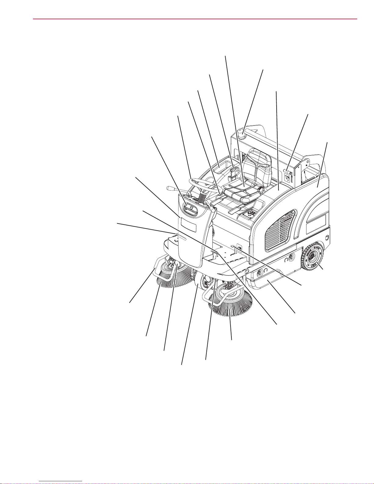
Driver's seat with safety microswitch
Machine Nomenclature (know your machine) (SW4000 Battery)
General Information
12
Seat position adjusting lever
Dust guard system
water filler neck plug
Front column / Dust guard
system water tank
Parking brake lever
Forward/reverse gear pedal
Safety belts
Can holder
Steering wheel
Flashing light
Battery compartment
hood
Hopper release
and discharge lever
Left
side
cover
Side broom guards
Right side broom
Working lights
Front driving and steering wheel
Rear
wheels
Front skirt
lifting pedal
Left door
Service brake pedal
Left side broom
Dust guard system nozzles
P200083
Page 13

Service Manual – SW4000
Serial number plate/technical
Machine Nomenclature (SW4000 Battery) (Continues)
data/conformity certification
Electronic
battery charger
Hopper manual
returning handle
Rear hood with
vacuum system
Dust filter
container
General Information
Drive pedal
Anchoring slots
for transport
(not for lifting)
13
Panel filter with
filter-shaker
Hopper
Anchoring slots for transport (not for lifting)
Right side cover
Right door
Main broom
Rear wheels
P200084
Page 14
Service Manual – SW4000
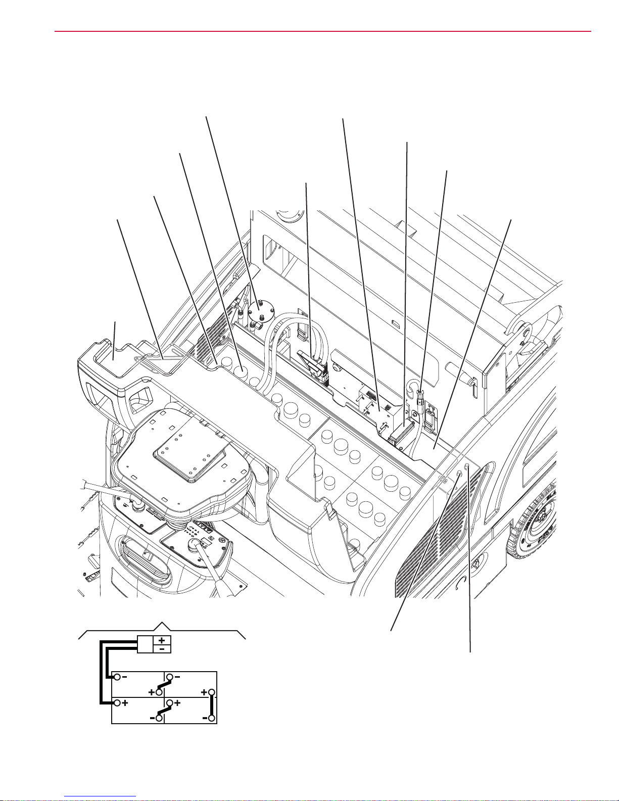
Hopper hydraulic
Machine Nomenclature (SW4000 Battery) (Continues)
lifting system
Battery caps
(for WET batteries only)
Lead batteries
(WET) or optional
gel batteries (GEL)
Open hood
safety rod
Battery
compartment
hood opening
handle
control unit
Battery
connector
Drive system electronic board
Fuseholder box
General Information
Vacuum system
motor connector
Electrical
component
box
14
Battery connection diagram
BATTERY
PLUG
6V
6V
6V
6V
Left side broom motor
circuit breaker
Right side broom
motor circuit breaker
P200085
Page 15
Service Manual – SW4000
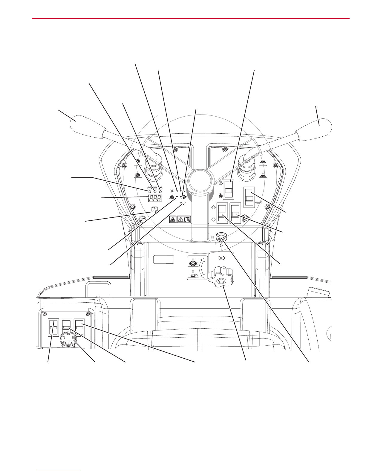
Switch for:
Vacuum system
Control Panel (SW4000 Battery)
General Information
15
Semi-discharged battery
warning light (yellow)
Main broom
lifting/lowering lever
Discharged
battery warning
light (red)
Display
Button:
• Working hours
• Battery voltage (V)
warning light
(green)
Charged
battery warning
light (green)
Dust guard system
warning light
(green)
• Vacuum system activation (upper part)
• Filter shaker activation (lower part)
Filter shaker switch
Hopper lifting
system warning
light (yellow)
Side broom
lifting/lowering lever
Horn switch
Hopper movement
enabling switch
Main broom overpressure
warning light (red)
Drive system malfunction
warning light (red)
Dust guard
system switch
Emergency
push-button
Hopper
lifting/lowering
switch
Working light
switch
Forward/reverse
gear switch
Main broom
height adjusting knob
Ignition key
P200086
Page 16
Service Manual – SW4000
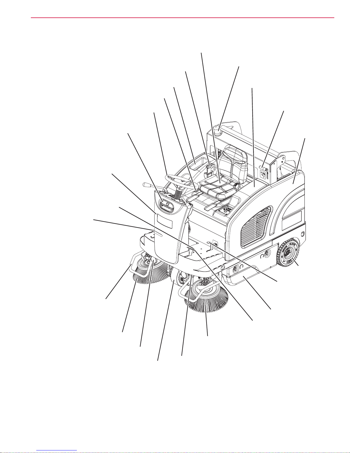
Driver's seat with safety microswitch
General Information
Machine Nomenclature (know your machine) (SW4000 Petrol/LPG)
Flashing light
Safety belts
16
Seat position adjusting lever
Dust guard system
water filler neck plug
Front column / Dust guard
system water tank
Parking brake lever
Drive pedal
Can holder
Steering wheel
Engine compartment
hood
Hopper release
and discharge
lever
Left
side
cover
Side broom guards
Right side broom
Working lights
Front driving and steering wheel
Rear
wheels
Front skirt
lifting pedal
Left door
Service brake pedal
Left side broom
Dust guard system nozzles
P200087
Page 17

Service Manual – SW4000
Serial number plate/technical data/
Machine Nomenclature (SW4000 Petrol/LPG) (Continues)
conformity certification
Filler plug
(SW4000 Petrol)
Hopper manual
returning handle
Rear hood with
vacuum system
Dust filter
container
Fuel tank
(SW4000 Petrol)
General Information
Drive pedal
Anchoring slots
for transport
(not for lifting)
17
Panel filter
with filter-shaker
Fuel opening/closing
valve (SW4000 Petrol)
Hopper
Right side cover
Right door
Main broom
Rear wheels
Anchoring slots for transport
(not for lifting)
P200088
Page 18

Service Manual – SW4000
Machine Nomenclature (SW4000 Petrol/LPG) (Continues)
Hopper hydraulic
lifting system control unit
Drive system electronic board
General Information
18
Open hood
safety rod
Engine
compartment
hood lifting
handle
Right side cover
Dynamotor
Engine
Batteries
Fuseholder box
Vacuum system
motor connector
Electrical
component
box
Choke lever
Engine serial number and model plate
LPG tank (SW4000 LPG)
LPG adjuster solenoid valve (SW4000 LPG)
LPG tank fastening band (SW4000 LPG)
Right side broom motor
circuit breaker
Left side broom motor
circuit breaker
Battery connection diagram
12V
12V
P200089
Page 19

Service Manual – SW4000
Switch for:
Vacuum
Control Panel (SW4000 Petrol/LPG)
General Information
19
Main broom
lifting/lowering
lever
Fuel reserve
warning light (yellow)
Display
Button:
• Working hours
• Battery voltage (V)
Main broom overpressure
warning light (red)
Drive system
malfunction warning
light (red)
system warning
light (green)
Dust guard
system warning
light (green)
Hopper lifting
system warning
light (yellow)
• Vacuum system activation (upper part)
• Filter shaker activation (lower part)
Filter shaker/vacuum system switch
Side broom
lifting/lowering lever
Horn switch
Hopper movement
enabling switch
Forward/reverse
gear switch
Dust guard
system switch
Emergency
push-button
Hopper lifting/lowering
switch
Working light
switch
Main broom height
adjusting knob
Ignition
key
P200090
Page 20

Service Manual – SW4000
General Information
Service and Diagnostic Equipment
Besides a complete set of standard meters, the following instruments are necessary to perform fast checks and
repairs on Nilsk-Advance machines:
Laptop computer charged with the current version of EzParts, Adobe Reader and (if possible) Internet con-
nection
• Digital Volt Meter (DVM)
• Amp clamp with possibility of making DC measurements
• Hydrometer
• Battery charge tester to check 12V batteries
• Static control wrist strap
• Dynamometric wrench set
• A copy of the User Manual and Spare Parts List of the machine to be serviced (provided with the machine
or available at www.advance-us.com or other Nilsk-Advance websites).
The following equipment is also available at Nilsk-Advance Centers:
• Italsea universal programmer, P/N 9097297000
20
P200091
Page 21

Service Manual – SW4000
General Information
Technical Data
Model SW4000 B SW4000 P SW4000 LP
Cleaning width with one side broom 38.3 in (975 mm)
with two side brooms 49.2 in (1,250 mm)
Main broom size (length x diameter) 27.6 x 13.4 in (700 x 340 mm)
Side broom diameter 17.7 in (450 mm)
Theoretical working capacity main broom 52,743 ft
with two side brooms 73,463 ft
with two side brooms 94,184 ft
Hopper capacity 19.8 US gal (75 liters)
maximum liftable weight 220 lb (100 kg)
maximum lifting height 62.6 in (1,590 mm)
Filter cleaning system Electrical lter shaker
area 75 ft
ltering capacity 4 µm
Power source 24 Volt batteries Power - 4,1 kW (5,5 CV) @ 3.600 giri/min
Engine model (*) - Honda GX-200
Tank capacity - 2 US gal
LPG Tank capacity - - 33 lb (15 Kg)
Main broom motor power 0.8 hp (600 W)
speed 550 rpm
Side broom motor power 0.12 hp (90 W)
speed 110 rpm
Vacuum motor power 0.35 hp (260 W)
Drive type Electric drive on front wheel
gearmotor power 1.35 hp (1,000 W)
forward speed 4.3 mi/h (7 km/h)
reverse speed 2.8 mi/h (4.5 km/h)
Maximum gradient when working 20 %
Hopper hydraulic control unit 0.33 hp (250 W)
Filter shaker motor 0.12 hp (90 W)
Total absorbed power 2.7 hp (2.0 kW)
Working autonomy 4,5 h 13 h 25 h
Dimensions
(length x width x height)
machine body 64.5 x 40.7 x 52.3 in (1,640 x 1,035 x 1,330 mm)
machine with side brooms 64.5 x 41.3 x 52.3 in (1,640 x 1,050 x 1,330 mm)
machine with ashing light 64.5 x 41.3 x 57.7 in (1,640 x 1,035 x 1,390 mm)
machine with FOPS protective roof (optional) 64.5 x 40.7 x 78.3 in (1,640 x 1,035 x 1,990 mm)
battery compartment 14.5 x 32 x 15.3
in (370x812x390
mm)
LPG tank maximum size (length x diameter) - - 28.3 x 11.8 in
2
/h (4,900 m2/h)
2
/h (6,825 m2/h)
2
/h (8,750 m2/h)
2
(7 m2)
(7,8 litres)
14.2 x 15 x 8.7 in
(360 x 380 x 220 mm)
-
(720 x 300 mm)
21
Page 22

Service Manual – SW4000
General Information
Technical Data (Continues)
Model SW4000 B SW4000 P SW4000 LP
Weight kerb weight without batteries 954 lb (433 Kg) - -
kerb weight - 1,126 lb (511 Kg) 1,135 lb (515 Kg)
total kerb weight (*) 1,816 lb (824 Kg) 1,309 lb (594 Kg) 1,371 lb (622 Kg)
front axle kerb weight (*) 696 lb (316 Kg) 553 lb (251 Kg) 560 lb (254 Kg)
rear axle kerb weight (*) 1,120 lb (508 Kg) 756 lb (343 Kg) 811 lb (368 Kg)
gross vehicle weight (GVW) 2,215 lb (1,005
Kg)
Wheel specic pressure on the oor (front - rear wheels, in running conditions) (**) 130 - 58 lbf/in
(0.9 - 0.4 N/mm2)
Sound pressure level at workstation (ISO 11201, ISO 4871, EN 60335-2-72) (LpA) 65 ±3 dB(A) 75 ±3 dB(A)
Machine sound pressure level (ISO 3744, ISO 4871, EN 60335-2-72) (LwA) 86 dB(A) 94 dB(A)
IP protection class X3
Dust guard system water tank (optional) capacity 5.3 US gal (20 liters)
U-turn space (right - left) 75.6 - 74.4 in (1,920 - 1,890 mm)
Vibration level at the operator’s arms (ISO 5349-1) < 98 in/s
Vibration level at the operator’s body (ISO 2631-1) < 19.6 in/s
(< 0.5 m/s2)
1,708 lb (775 Kg) 1,770 lb (803 Kg)
2
2
116 - 29 lbf/in
(0.8 - 0.2 N/mm2)
2
(< 2.5 m/s2)
< 35.4 in/s
(< 0.9 m/s2)
2
2
22
(*) With operator on board, without batteries and with hopper empty.
(**) Machines have been tested under the following conditions:
• With operator on board (165.3 lb - 75 kg)
• Battery of maximum size
• Brooms of maximum size
• Full Tanks
• Optional components installed
• Weight on wheels checked
• Print on the oor checked on cement for each single wheel
Result expressed as maximum value for both front and rear wheels
Machine material composition and recyclability
Type
Aluminium 100 % 0.0 % 0,0 % 0,0 %
Electric motors - various 29 % 10.8 % 21,1 % 21,1 %
Ferrous materials 100 % 53.5 % 48,3 % 48,8 %
Wiring harnesses 80 % 1.2 % 0,8 % 0,8 %
Liquids 100 % 0.4 % 0,5 % 0,5 %
Plastic - non-recyclable material 0 % 1.0 % 0,9 % 0,8 %
Plastic - recyclable material 100 % 9.8 % 8,6 % 8,4 %
Polyethylene 92 % 7.0 % 6,0 % 5,9 %
Rubber 20 % 4.1 % 3,5 % 3,5 %
Cardboard - paper - wood 100 % 12.2 % 10,3 % 10,2 %
Recyclable
percentage
SW4000 B
weight
percentage
SW4000 P
weight
percentage
SW4000 LP
weight
percentage
Page 23

Service Manual – SW4000
Technical Data (Continues)
Caution! If the machine is to be used at ambient temperatures below +10°C, the oil should be
changed with equivalent oil having a viscosity of 32 cSt. For temperatures below 0°C,
use an oil with lower viscosity.
Hydraulic oil technical data
AGIP ARNICA 46 32
Viscosity at 104 °F (40 °C) in
Viscosity at 212 °F (100 °C) in
Viscosity index / 150 157
Flash point COC °F (°C) 419 (215) 396 (202)
Pour point °F (°C) -32.8 (-36) -32.8 (-36)
Density at 15 °C (59 °F) lb/gal (kg/l) 1.9 (0.87) 1.9 (0.865)
2
/s (mm2/s) 0.07 (45) 0.05 (32)
2
/s (mm2/s) 0.012 (7.97) 0.009 (6.40)
General Information
23
Page 24

Service Manual – SW4000
Dimensions
General Information
24
1330 mm (52.4 in)
1065 mm (42 in)1640 mm (64.6 in)
P200092
Page 25

Service Manual – SW4000
General Information
Maintenance
The lifespan of the machine and its maximum operating safety are ensured by correct and regular maintenance.
Warning! Read carefully the instructions in the Safety chapter before performing any
maintenance procedure.
The following tables provides the scheduled maintenance. The intervals shown may vary according to particu-
lar working conditions, which are to be dened by the person in charge of the maintenance.
For instructions on maintenance procedures, see the following paragraphs.
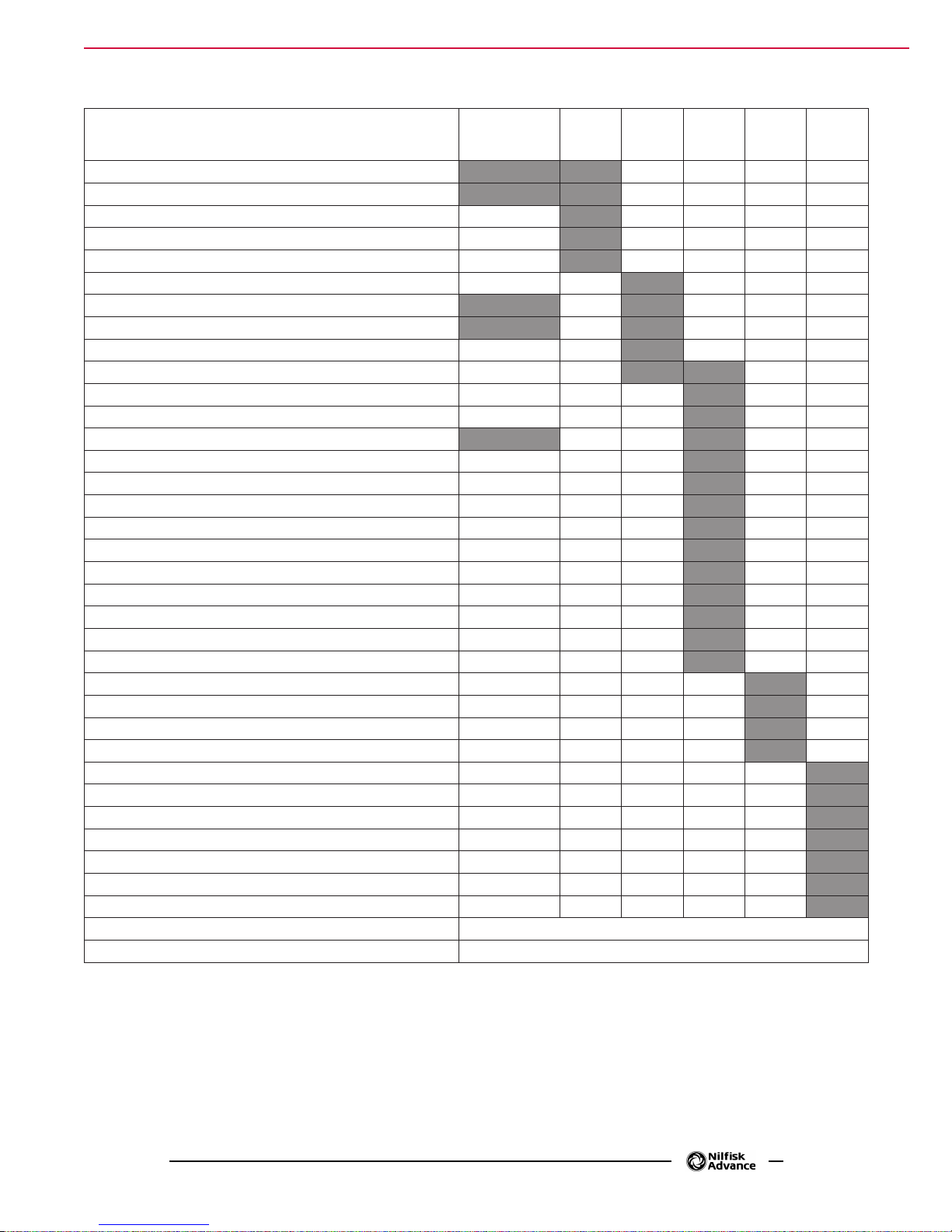
Scheduled Maintenance Table (SW4000 Battery)
Procedure
Battery charging (1)
Battery (WET) uid level check (2)
Side and main broom height check
Service brake cable adjustment (3)
Hopper dust lter check and cleaning (“A” method) (4)
Hopper hydraulic lifting system oil level check (2)
Skirt height and operation check
Dust guard system water lter check and cleaning
Hopper dust lter check and cleaning (“B” method) (4)
Filter shaker operation check
Main broom driving belt check
Brake adjustment
Nut and screw tightening check (5)
Steering chain cleaning
Safety system operation check (2)
Brake pad check/adjustment/replacement (3)
Hopper dust lter check and cleaning (“C” method) (4)
Main broom driving belt replacement
Hopper gasket integrity check
Lifted hopper sensor operation check/adjustment
Motor carbon brush check and replacement
Hydraulic system oil change (6)
Upon
delivery
Every
10
hours
Every
50
hours
Every
100
hours
Every
200
hours
Every
year
25
(1) Daily or after using the machine.
(2) Or before start-up.
(3) Or more frequently if the machine is used on slopes.
(4) Or more often in dusty areas.
(5) And after the rst 8 running-in hours.
(6) Change the hydraulic system oil for the rst time after 500 hours, then every 2,000 hours or every year.
Page 26
Service Manual – SW4000
General Information
Scheduled Maintenance Table (SW4000 Petrol/LPG)
Procedure
Engine oil level check (1)
Battery uid level check (2)
Side and main broom height check
Engine air lter check (1)
Service brake cable adjustment (3)
Hopper dust lter check and cleaning (“A” method) (4)
Hopper hydraulic lifting system oil level check (2)
Skirt height and operation check
Dust guard system water lter check and cleaning
Engine air lter cleaning (4) (4)
Hopper dust lter check and cleaning (“B” method) (4)
Filter shaker operation check
Main broom driving belt visual inspection
Brake replacement
Engine oil change (5) (6)
Spark plug check/cleaning
Nut and screw tightening check (6)
Steering chain cleaning (*)
Safety system operation check (2)
Engine lter trap cleaning
Engine bafe plate cleaning
Fuel lter cleaning (7)
Brake pad check/adjustment/replacement (3)
Hopper dust lter check and cleaning (“C” method) (4)
Main broom driving belt replacement
Hopper gasket integrity check
Lifted hopper sensor operation check/adjustment
Fuel valve lter cleaning (Petrol)
Engine paper air lter replacement
Spark plug replacement
Engine idle speed check/adjustment
Valve clearance check/adjustment (7)
Hydraulic system oil change (8)
Supply hose replacement (LPG)
Engine combustion chamber check Every 500 hours (7)
Fuel hose check/replacement (Petrol) Every 2 years (7)
Upon
delivery
Every
10
hours
Every
50
hours
Every
100
hours
Every
200
hours
26
Every
year
(1) Daily or after using the machine.
(2) Or before start-up.
(3) Or more frequently if the machine is used on slopes.
(4) Or more often in dusty areas.
(5) Or every 6 months.
(6) And after the rst 20 running-in hours.
(7) Maintenance procedures to be performed by an authorised Honda dealer.
(8) Change the hydraulic system oil for the rst time after 500 hours, then every 2,000 hours or every year.
Page 27
Service Manual – SW4000
4
Chassis System
Chassis System
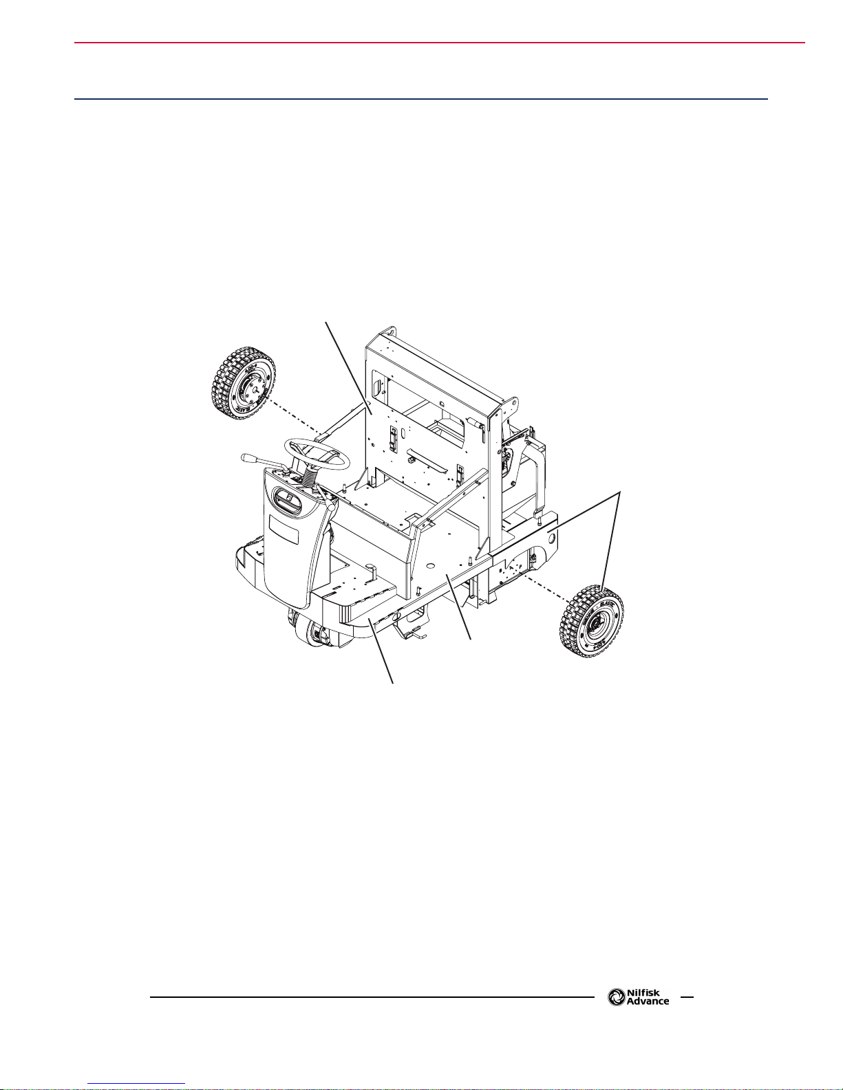
Chassis (main parts)
1. Front side supporting the steering assembly and side brooms.
2. Center side supporting batteries/engine with dynamotor and main broom.
3. Rear side supporting the hopper and rear wheels on hubs.
4. Central holder for separating wall between engine compartment/vacuum system compartment, and for
supporting the hopper lifting linkages.
27
3
2
1
P200093
Page 28

Control System 28Service Manual – SW4000
Control System
Functional Description
The machine is started by the ignition key (SW1), located on the steering column.
The key starts the machine when turned to II, thus powering the relay (K4). The relay (K4) stays on even when
the key returns to I. All the accessories (except the buzzer) are on only when the relay (K4) is on too.
Ahead of the ignition key (SW1) there is the emergency push-button (SW0). The key circuit is protected by the
relevant fuse (F4).
The machine different functions are mainly controlled by the switches located on the main dashboard (on the
steering column) and on the secondary dashboard (beside the driver’s seat) and by the 2 broom levers.
For functions not requiring an electronic management, the switches operate directly or by means of relays,
on the relevant drives. For functions requiring timers or electronic controls, the commands generated when
operating the switches are read by the dashboard electronic board (EB2) which drives the outputs directly or
by means of external relays.
The electric drive system control is made by the forward/reverse gear switch (SW2) and the gear pedal (R1)
which provide signals to the drive system electronic board (EB1).
For all the details concerning the described functions, see the relevant chapters.
Page 29

Control System 29Service Manual – SW4000
DashboardElectronicBoardSpecications
The dashboard electronic board performs the following:
a. HOUR COUNTER: By default, the 3-digit display (A) shows the number of hours stored in the hour
counter. The hour counter proceeds with counting, only when the main broom turns. When the hour
counter reaches 999, the next numbers are shown by the 3 more meaningful digits by adding a (low)
dot for separating thousands (i.e.: 1234 will be shown as 1.23).
b. BATTERY VOLTAGE DISPLAY: by pressing the push-button (B) (with the machine running)
the display will switch from the 3-digit hour counter (A) to the battery voltage. The display will
automatically return to the hour counter 5” after the last pressing of the push-button (B).
c. MAIN BROOM MOTOR PROTECTION: By reading the voltage drop on main broom fuse (FA), the
main broom motor amperage (M4) is monitored. If the voltage drop is higher than 40mV, the warning
light (C) starts ashing. If this condition persists, after a time inversely proportional to the value of
voltage drop detected, the broom motor is stopped (the warning light continues to ash). To reset,
turn the ignition key on and off (SW1).
A
B
C
P200219
Page 30

Control System 30Service Manual – SW4000
EF
d. BATTERY PROTECTION: Battery charge status is shown by the 3 LEDs depending on the type of
battery (WET/GEL) according to the following diagram:
WET GEL
1 Green LED on (xed) V>22.0 V>22.2
2 Yellow LED on (xed) 22.0>V>20.4 22.2>V>21.6
3 Red LED ashing V>20.4 V>21.6
When the red LED starts ashing, broom function is automatically deactivated.
e. BATTERY TYPE DISPLAY (WET/GEL): Each time the machine is turned on with the ignition
key, the 3 battery charge LED indicators show the battery type as follows:
Battery Type Flashing pattern
WET 4 ashes of the RED warning light
GEL 4 ashes of the GREEN warning light
f. PROCEDURE FOR BATTERY SETTING (WET/GEL): Hold the push-button (B) down while
you turn the key on and hold it for 5 sec. The 3 LEDs will then show again the current setting with
the continuous ashing of the corresponding LED (see the previous step), while further pressing
the push-button (B) will change the current setting. The last setting will be stored when (B) is not
pressed for more than 5 sec.
g. TIMED FUNCTION ACTIVATION: BROOM, VACUUM and FILTER SHAKER are turned on and
off by pressing the relevant controls and according to the conditions of the relevant sensors as shown
in their respective chapters
OTHER INDICATIONS WITH DEDICATED WARNING LIGHTS: fuel reserve warning light
(D), vacuum system warning light (E), dust guard system warning light (F), hopper lifting warning
light (G), main broom overpressure warning light (C), drive system diagnostic warning light (I).
G
D
B
C
I
P200220
Page 31

Wiring Diagram (SW4000 Battery)
Control System 31Service Manual – SW4000
HOPPER
TEMPERATURE
REVERSE GEAR
BUZZER (BZ1)
FILTER SHAKER/
VACUUM SYSTEM
SWITCH (SW3)
HORN SWITCH (SW6)
SENSOR (S4)
HORN (HN)
VACUUM SYSTEM
FILTER SHAKER
RELAY (K1)
DISPLAY
ELECTRONIC
BOARD FUSE (F3)
J1.1 - Electronic board power supply +
J1.14 - Electronic board congurator return
J1.13 - Key return
J1.11 - Vacuum system relay power supply
J1.12 - Filter-shaker relay power supply
J2.4 - Control panel switch power supply (-)
J1.15 - Fire alarm signal
J2.2 - Vacuum system activation signal
CONTROL PANEL ELECTRONIC BOARD (EB2)
J1.17 - Water pump activation signal
J2.3 - Filter-shaker activation signal
J2.1 - Control panel switch power supply (+)
J1.4 - Broom fuse voltage drop reading +
J1.5 - Broom fuse voltage drop reading -
J1.2 - Broom activation lever signal
J1.10 - Broom electromagnetic switch power supply
J1.8 - Lifted hopper signal
J1.7 - Drive system electronic board diagnostic signal
J1.18 - Machine moving signal
J1.9 - Electronic board power supply -
POSITIVE SIGNAL
(FROM MACHINE ON “K4”)
BATTERY NEGATIVE TERMINAL
RELAY (K2)
HOPPER LIFTING
SENSOR (S1)
HOPPER LOWERING
RELAY (K3B)
MAIN BROOM
LEVER SENSOR (S2)
A
HOPPER LIFTING
RELAY (K3A)
HOPPER ENABLING
SWITCH (SW4)
HOPPER LIFTING/LOWERING
SWITCH (SW5)
DUSTGUARD™
SWITCH (SW8)
DUSTGUARD™
PUMP RELAY (K6)
SIDE BROOM
LEVER SENSOR (S3)
SIDE BROOM
RELAY (K5)
MAIN BROOM
ELECTROMAGNETIC
SWITCH (ES1)
B
C
D
E
P200094A
Page 32

Wiring Diagram (SW4000 Battery)
Control System 32Service Manual – SW4000
POSITIVE SIGNAL
(FROM MACHINE ON “K4”)
BATTERY NEGATIVE TERMINAL
A
LINE ELECTROMAGNETIC
SWITCH (ES0)
KEY CIRCUIT FUSE (F4)
IGNITION KEY (SW1)
MACHINE ON
RELAY (K4)
EMERGENCY
PUSH-BUTTON (SW0)
B
C
D
E
DRIVE SYSTEM
ELECTRONIC BOARD (EB1)
J2.15 - Key input
J2.11 - Lifted hopper input
J2.10 - Diagnostic warning light output
J2.7 - Machine moving signal
WORKING
LIGHT SWITCH
(SW9)
WORKING
LIGHT (L1)
WORKING
LIGHT (L2)
MACHINE ON
RELAY (K4)
P200094B
Page 33

Wiring Diagram (SW4000 Petrol/LPG)
Control System 33Service Manual – SW4000
FUEL RESERVE
SENSOR (S4)
REVERSE GEAR
BUZZER (BZ1)
FILTER SHAKER/
VACUUM SYSTEM
SWITCH (SW3)
HORN SWITCH (SW6)
HORN (HN)
DISPLAY ELECTRONIC
BOARD FUSE (F3)
J1.14 - Electronic board congurator return
J1.13 - Key return
J1.6 - Fuel reserve signal
J1.15 - Fire alarm signal
J2.2 - Vacuum system activation signal
CONTROL PANEL ELECTRONIC BOARD (EB2)
J2.3 - Filter-shaker activation signal
J2.1 - Control panel switch power supply (+)
J1.4 - Broom fuse voltage drop reading +
J1.5 - Broom fuse voltage drop reading -
VACUUM SYSTEM
RELAY (K1)
J1.1 - Electronic board power supply +
J1.11 - Vacuum system relay power supply
J1.12 - Filter-shaker relay power supply
J2.4 - Control panel switch power supply (-)
J1.17 - Water pump activation signal
J1.2 - Broom activation lever signal
J1.10 - Broom electromagnetic switch power supply
J1.8 - Lifted hopper signal
J1.7 - Drive system electronic board diagnostic signal
J1.18 - Machine moving signal
J1.9 - Electronic board power supply -
POSITIVE SIGNAL
(FROM MACHINE ON “K4”)
BATTERY NEGATIVE TERMINAL
FILTER SHAKER
RELAY (K2)
MAIN BROOM
LEVER SENSOR (S2)
HOPPER LIFTING
SENSOR (S1)
HOPPER LOWERING
RELAY (K3B)
HOPPER LIFTING
RELAY (K3A)
HOPPER ENABLING
SWITCH (SW4)
HOPPER LIFTING/LOWERING
SWITCH (SW5)
DUSTGUARD™
SWITCH (SW8)
DUSTGUARD™
PUMP RELAY (K6)
SIDE BROOM LEVER
SENSOR (S3)
SIDE BROOM
RELAY (K5)
MAIN BROOM
ELECTROMAGNETIC
SWITCH (ES1)
A
B
C
D
E
P200095A
Page 34

Wiring Diagram (SW4000 Petrol/LPG)
Control System 34Service Manual – SW4000
POSITIVE SIGNAL
(FROM MACHINE ON “K4”)
BATTERY NEGATIVE TERMINAL
A
LINE
ELECTROMAGNETIC
SWITCH (ES0)
KEY CIRCUIT FUSE (F4)
EMERGENCY PUSH-BUTTON (SW0)
IGNITION
KEY (SW1)
ENGINE SPARK
PLUG (SPK)
FRAME (FR)
DRIVE SYSTEM ELECTRONIC
BOARD (EB1)
WORKING LIGHT
SWITCH (SW9)
J2.15 - Key input
WORKING
LIGHT (L1)
WORKING
B
C
D
E
J2.11 - Lifted hopper input
J2.10 - Diagnostic warning light output
J2.7 - Machine moving signal
LIGHT (L2)
LPG SAFETY TIMER
RELAY (KT1)
LPG SAFETY
SOLENOID VALVE (EV1)
Only for LPG version
MACHINE ON
RELAY (K4)
DIODE
(D3)
ENGINE START
ELECTROMAGNETIC
SWITCH (ES2)
P200095B
Page 35

Component Locations
• Dashboard
• Dashboard electronic board (EB2)
• Ignition key (SW1)
Dashboard
electronic
board (EB2)
Control System 35Service Manual – SW4000
Dashboard
Ignition key
(SW1)
P200096
Page 36

Troubleshooting
Trouble Possible Cause Remedy
(For SW4000 Battery)
When turning the ignition key to “II”, the
display does not turn on and the machine
does not operate.
(For SW4000 Petrol/LPG)
“L O U” (A) (Low Voltage) display indication
(For SW4000 Petrol/LPG)
“H I U” (A) (High Voltage) ashing display
indication
Control System 36Service Manual – SW4000
The battery connector is disconnected. Connect the battery connector.
The fuse (F3) and/or (F0) is open. Check/replace the fuses.
The emergency push-button has been
pressed.
Battery voltage lower than 24.0 V.
Battery voltage higher than 32.4V.
Check and release the emergency pushbutton.
Decrease the main broom pressure on the
oor.
“L O U” (A) (Low Voltage) display indication
If the problem persists, it may be necessary
to calibrate the engine rpm (see Petrol
Engine – LPG Engine chapter).
Turn off the engine each time the machine is
stopped.
If the problem persists, it may be necessary
to calibrate the engine rpm (see Petrol
Engine chapter).
A
P200247
Page 37

Control System 37Service Manual – SW4000
Dashboard Electronic Error Codes
The drive system warning light (A) on the dashboard electronic board (EB2) shows the error codes of the drive
system electronic board (EB1). For the details, see the Wheel System, Drive chapter.
A
P200097
Page 38

Connectors on the dashboard electronic board
J1: MOLEX MINIFIT type, 18-ways vertical (A)
101112131415161718
123456789
Control System 38Service Manual – SW4000
A
P200221
PIN Description Electronic
board in/out
1 Electronic board power supply + in 24V 3A F10
2 Broom activation lever signal in 24V (when the description is ON) <1A S2
3 Engine on signal in 24V (when the description is ON) <1A K4.30
4* Broom fuse voltage drop reading + in 0V (when the description is OFF) <1A FA +
5* Broom fuse voltage drop reading - in 0V (when the description is OFF) <1A FA-
6 Fuel reserve signal in 0V (when the description is OFF) <1A S5
7 Drive system electronic board diagnostic signal in (24V) <1A EB1.J2.10
8 Lifted hopper signal in 24V (when the description is ON) <1A S1
9 Electronic board power supply - in 0V (when the description is OFF) 3A -B
10 Broom electromagnetic switch power supply out 0V (when the description is OFF) 1A ES1, K5
11 Vacuum system relay power supply out 0V (when the description is OFF) 1A K1.85
12 Filter shaker relay power supply out 0V (when the description is OFF) 1A K2.85
13 Return from key in 24V (when the description is ON) <1A K4.30/SW1
14** Electronic board congurator return (Battery) in 24V (when the description is ON) <1A K4.30
15 Fire alarm signal in 0V (when the description is OFF) <1A S4
16 Hopper lifting control out 0V (when the description is OFF) 1A K3A.85
V ref. I max. Connected to
17 Water pump activation signal in 24V (when the description is ON) <1A SW8.2
18 Machine moving signal in 0V (when the description is OFF) <1A EB1.7
Page 39

Control System 39Service Manual – SW4000
CBA
J1: MOLEX MINIFIT type, 18-ways vertical (A) (continues)
Further notes about dashboard electronic board (PIN - J1.14)
The dashboard electronic board (EB2) recognises if it has been assembled on a Battery or Petrol/LPG machine
version depending on the PIN J1.14 status:
• PIN J1.14 - connected to +24V = Battery version,
• PIN J1.14 - NOT connected = Petrol/LPG version .
Battery version (PIN - J1.14 at +24V)
SAFETY BATTERY FUNCTION: The battery loading status is displayed by means of 3 LEDs
(A) Green, (B) Yellow, (C) Red, up to the battery type installed (WET/GEL) as shown below:
Threshold values Threshold values of change
1 LED (A) Green xed <=> LED (B) Yellow xed 22,0 22,2
2 LED (B) Yellow xed <=> LED (C) Red ashing 1Hz 20,4 21,6
status (V, toll.±0,1)
WET GEL
The change status is ltered with a 3 sec. delay as regards to the battery tension reading.
When threshold value 2 is reached, the J1.10 output is automaticaly shutted off with 5 sec. delay.
Without any regards to the battery tension reading value the change values status 2 is xed. The only way to
reset the status is the machine switching off by using the ignition key (SW1).
P200247b
Page 40

Control System 40Service Manual – SW4000
J1: MOLEX MINIFIT type, 18-ways vertical (A) (continues)
Petrol/LPG version (PIN - J1.14 not connected)
The RPM value of the Petrol/LPG engine is xed to 2.750 rpm ± 50 rpm
The xed RPM value of the Petrol/LPG engine should be in any case as follows
• with the loaded batteries, engine On, all functions Off => the battery tension is between 27,0V and
31,0V
• with the loaded batteries, engine On, all functions On => the battery tension is higher than 24,0V
The dashboard electronic board (EB2) displays 2 alarms, shown by the display (A) and the LED (B) ashed, if
are not matched for more than 5 consecutive minutes the following conditions:
Shown on display Battery conditions Solution Alternative actions in case the
L O U V < 24,0V (Low Voltage) Avoid using the machine for long
H I U V > 32,4V (High
Voltage)
periods at maximum power or on
slopes: leave the engine running with
all features turned off for at least ten
minutes after each usage.
Turn the engine off when you are not
working: do not leave the machine
for long periods without using any
functions.
solution does not solve the problem
Recharge the battery with a suitable
charger and then adjust the engine RPM
(increase the engine RPM till reach
again the recommended tension ranges).
Adjust the RPM engine (reduce the
engine RPM till reach again the
recommended tension ranges).
AB AB
P200247a
Page 41

J2: MOLEX MINIFIT type, 4-ways vertical (B)
B
34
12
Control System 41Service Manual – SW4000
P200098
PIN Description Electronic
board in/out
1 Dashboard switch power supply (+) out 24V <1A SW3, SW8
2 Vacuum system activation signal in 24V (when the description is ON) <1A SW3.1
3 Filter-shaker activation signal in 24V (when the description is ON) <1A SW3.3
4 Dashboard switch power supply (-) out 0V <1A SW4
V ref. I max. Connected to
Page 42

Removal and Installation
Dashboard Electronic Board Disassembly/Assembly
Control System 42Service Manual – SW4000
Disassembly
1. Drive the machine on a level oor.
2. Turn the ignition key to “0” and engage the
parking brake.
3. Open the battery/engine compartment hood.
Disconnect the battery connector (SW4000
Battery) - Disconnect the batteries (SW4000
Petrol/LPG).
4. Remove the fastening screws (A) of the fairing
(B) from the steering column.
5. Slightly lift the steering column (B) by
disengaging it from the lower fastener (C).
6. Disconnect the dust guard system quick coupling
(D).
A
A
A
7. Retrieve the fairing (B).
8. Under the left side of the control panel,
disconnect the connectors (E) of the dashboard
electronic board (F).
9. Disengage the four nuts (G) and remove the
dashboard electronic board (F).
Assembly
10. Assemble the components in the reverse order of
disassembly, and note the following:
• Set the type of batteries installed on the ma-
chine (see Electrical System chapter).
B
C
B
A
G
E
F
G
D
P200101
Page 43

Dust Control System 43Service Manual – SW4000
Dust Control System
Functional Description
The dust raised in the compartment of the main broom, is collected in the rear cargo area by a ow of air generated by the dust control system.
The lter located between the vacuum system and the hopper, retains dirt which is then conveyed through a
feedbox into the hopper itself.
The operation of the system depends on the activation of the main broom.
By deactivating the main broom, the dust control system turns off automatically.
There is a vacuum system motor (M1) which is powered by the relay (K1) and protected by the fuse (F1).
The relay (K1) is directly controlled by the dashboard electronic board (EB2) according to the information re-
ceived by the vacuum system/lter shaker switch (SW3), by the sensor on the broom activation lever (S2), by
the machine moving signal received by the drive system electronic board(EB1) and by the lifted hopper sensor
(S1).
Normally the vacuum function is turned on when the main broom is lowered with the lever; it can, however,
be turned on or off independently with the push-button SW3, it turns off when the machine is stopped, when
the hopper is lifted and during activation the electric lter shaker.
There is an electric lter shaker motor (M2) which is powered by the relay (K2) and protected by the fuse (F2).
The relay (K2) is directly controlled by the dashboard electronic board (EB2) according to the information re-
ceived by the vacuum system/lter shaker switch (SW3): When the button is activated for a cycle of 20 seconds
during which it is driven 0.5 sec ON and 0.5 sec. OFF for continuously modulating the number of revolutions
and the resulting vibration frequencies of the lter.
The vibrating motor shakes the lter allowing dirt trapped in the folds of the same to fall by gravity into the
hopper.
This reduces lter maintenance and helps to maintain proper airow through the lter.
Wiring Diagram
VACUUM
SYSTEM FUSE (F1)
FILTER SHAKER
FUSE (F2)
FILTER SHAKER/VACUUM
SYSTEM SWITCH (SW3)
FILTER SHAKER RELAY (K2)
VACUUM SYSTEM RELAY (K1)
M2M1
FILTER SHAKER MOTOR
VACUUM SYSTEM MOTOR
DISPLAY ELECTRONIC
BOARD FUSE (F3)
J2.2 - Vacuum system activation signal
CONTROL PANEL ELECTRONIC
BOARD (EB2)
J2.3 - Filter-shaker activation signal
J2.1 - Control panel switch power supply (+)
VACUUM
SYSTEM RELAY (K1)
J1.1 - Electronic board power supply +
J1.11 - Vacuum system relay power supply
J1.12 - Filter-shaker relay power supply
J1.2 - Broom activation lever signal
J1.8 - Lifted hopper signal
J1.9 - Electronic board power supply -
J1.18 - Machine moving signal
FILTER SHAKER RELAY (K2)
MAIN BROOM
LEVER SENSOR (S2)
HOPPER LIFTING
SENSOR (S1)
POSITIVE SIGNAL
(FROM MACHINE ON “K4”)
BATTERY NEGATIVE TERMINAL
DRIVE SYSTEM
ELECTRONIC BOARD (EB1)
J2.11 - Lifted hopper input
J2.7 - Machine moving signal
P200102
Page 44

Component Locations
• Filter shaker/vacuum system switch (SW3)
• Vacuum system motor (M1)
• Gasket
• Filter shaker motor (M2)
Dust Control System 44Service Manual – SW4000
• Panel lter
• Vacuum system motor fuse (25 A - Battery) (30 A
Petrol/LPG) (F1)
• Filter shaker motor fuse (25 A - Battery) (30 A
Petrol/LPG) (F2)
Filter
shaker/vacuum
system switch (SW3)
Gasket
Filter shaker
motor (M2)
Filter shaker
motor fuse
(25 A - Battery)
(30 A Petrol/LPG) (F2)
Vacuum system
motor (M1)
Panellter
Vacuum system
motor fuse
(25 A - Battery)
(30 A Petrol/LPG) (F1)
P200103
Page 45

Dust Control System 45Service Manual – SW4000
CBB
Maintenance and Adjustments
Panel Dust Filter Cleaning and Integrity Check
Caution! Thedustltermustberegularlycleanedtomaintaintheefciencyofthevacuum
system.Followtherecommendedlterserviceintervalsforthelongestlterlife.
Warning! -Wearsafetyglasseswhencleaningthelter.
-Donotpuncturethelter.
-Cleanthelterinawell-ventilatedarea.
- Wear appropriate dust mask to avoid breathing in dust.
1. Drive the machine on a level oor, engage the parking brake and turn the ignition key to “0”.
2. Open the battery/engine compartment hood with the handle and fasten it with the support rod.
3. Disconnect the battery connector (SW4000 Battery) - Disconnect the batteries (SW4000 Petrol/LPG).
4. Disconnect the vacuum system motor connector (A).
5. Disengage the retainers (B) and remove the vacuum system hood (C).
B
B
A
P200223
Page 46

G
Panel Dust Filter Cleaning and Integrity Check (Continues)
Dust Control System 46Service Manual – SW4000
6. (Only for LPG SW4000). Disconnect the lter
shaker connector (K).
7. Loosen the knobs (D) and (E), then remove the
lter shaker assembly (F), by sliding it forward,
disengaging it by the knobs (D) and then by the
knobs (E).
8. (Only for SW4000 Battery and Petrol). Fasten
the lter shaker assembly (F) to the holder (G).
9. (Only for LPG SW4000). Remove the lter
shaker assembly (F).
10. Lift the dust lter (H) and remove it from the
machine.
11. Clean the dust lter using one of the methods
below:
Method “A”
Vacuum loose dust from the lter. Gently tap the lter against a at surface (with the dirty side down) to
remove dust and dirt.
Caution! Take care not to damage the
metallipwhichextendspast
the gasket.
12. Assemble the dust lter in the reverse order of
disassembly and note the following:
• Clean the lter housing.
• If the lter gasket is damaged or missing, it
must be replaced.
• Install the lter with the strainer facing up-
wards (arrow (I) upwards).
E
F
K
E
Method “B”
Vacuum loose dust from the lter. Blow compressed
air (maximum pressure 6 Bar) into the clean side of
the lter (in the opposite direction of the airow).
Method “C”
Vacuum loose dust from the lter. Then soak the lter
in warm water for 15 minutes, then rinse it under a
gentle stream of water (maximum pressure 2.5 Bar).
Let the lter dry completely before installing it back
into the machine.
For a better cleaning, it is allowed to wash the lter
with water and non-lathering detergents.
This provides better quality cleaning but reduces the
life of the lter, which will have to be replaced more
frequently. The use of inadequate detergents can
damage the lter.
Caution! Forpaperlter:Donotuse
water or detergents to clean it,
otherwise it can be damaged.
DHID
P200104
Page 47

Troubleshooting
Trouble Possible causes Remedy
Dust Control System 47Service Manual – SW4000
Dust/debris vacuuming is insufcient The lter is clogged Clean the dust lter by using the lter shaker
The vacuum system compartment gasket is
damaged
No vacuuming The fuse (F1) is open. Replace the fuse.
The switch (SW3) is not efcient Replace
The relay (K1) is not efcient Replace
The vacuum system is broken Repair/replace
The lter shaker does not operate. The fuse (F2) is open. Replace the fuse.
The lter shaker is disconnected. Connect the lter shaker connector.
The switch (SW3) is not efcient Replace
The relay (K2) is not efcient Replace
The lter shaker is broken Repair/replace
or by disassembling it.
Repair/replace
Page 48

Dust Control System 48Service Manual – SW4000
Removal and Installation
Filter Shaker Motor Disassembly/Assembly
Disassembly
1. Drive the machine on a level oor, engage the parking brake and turn the ignition key to “0”.
2. Open the battery/engine compartment hood with the handle and fasten it with the support rod.
3. Disconnect the battery connector (SW4000 Battery) - Disconnect the batteries (SW4000 Petrol/LPG).
4. Disconnect the vacuum system motor connector (A).
5. Disengage the retainers (B) and remove the vacuum system hood (C).
A
P200105
Page 49

Dust Control System 49Service Manual – SW4000
CBB
Filter Shaker Motor Disassembly/Assembly (Continues)
6. Release the fastening clamp and disconnect the lter shaker connector (K).
7. Loosen the knobs (D) and (E), then remove the lter shaker assembly (F), by sliding it forward,
disengaging it by the knobs (D) and then by the knobs (E).
8. At the workbench, remove the nuts (G) and remove the fastening clamps (H) of the lter shaker motor
(I). Retrieve the washers (J).
9. Remove the lter shaker motor (H), by disengaging the dowel (L) from its seat.
Assembly
10. Assemble the components in the reverse order of disassembly.
B
B
I
L
E
H
F
K
E
DD
J
G
P200106
Page 50

Dust Control System 50Service Manual – SW4000
Electric Vacuum Fan Motor Amperage Check
Warning! Thisproceduremustbeperformedbyqualiedpersonnelonly.
1. Clean the dust lter.
2. Open the battery/engine compartment hood with the handle and fasten it with the support rod.
3. Apply the amp clamps (A) on one cable (B) of the electric vacuum fan (C).
4. Turn the ignition key to “I”.
5. With the help of an assistant, carefully press on the driver’s seat to activate the microswitch, then turn
on the vacuum system and check that the electric fan motor amperage is within 7 and 9 A at 24 V.
Stop the vacuum system.
Turn the ignition key to “0”.
Remove the amp clamps (A).
If the amperage is higher, perform the following procedures to detect and correct it:
• Check that the F1 fuse is properly tightened
• Remove the electric fan motor (see the procedure in the next paragraph), and check the condition of
all its components.
If the above-mentioned procedures do not produce the correct readings for the electric fan motor
amperage, the motor must be replaced (see the procedure in the relevant paragraph).
Reassembly
6. Close the battery/engine compartment hood.
C
B
A
P200107
Page 51

Dust Control System 51Service Manual – SW4000
CBB
Electric Fan Disassembly/Assembly
Disassembly
1. Drive the machine on a level oor, engage the parking brake and turn the ignition key to “0”.
2. Open the battery/engine compartment hood with the handle and fasten it with the support rod.
3. Disconnect the battery connector (SW4000 Battery) - Disconnect the batteries (SW4000 Petrol/LPG).
4. Disconnect the vacuum system motor connector (A).
5. Disengage the retainers (B) and remove the vacuum system hood (C).
A
B
B
P200108
Page 52

Dust Control System 52Service Manual – SW4000
Electric Fan Disassembly/Assembly (Continues)
6. At the workbench, disconnect the connector (D) from the electrical cable (E), by disengaging its pins.
7. Unscrew the bulkhead cap (F).
8. Remove the external screws (G) and remove the electric fan assembly (H) with its wiring harness (E).
9. If necessary, remove the electric vacuum fan (I) from the assembly (H) as shown below.
• Unscrew the three nuts (J) and remove the screws (K).
• Remove the plate (L) and the electric fan (I).
Assembly
10. Assemble the components in the reverse order of disassembly.
G D
E
F
J
L
G
H
I
J
J
K
J
H
P200109
Page 53

Specications
Dust Control System 53Service Manual – SW4000
Dust Control System
SW4000 Battery SW4000 Petrol SW4000 LPG
Vacuum system motor 0.35 hp (260 W) - 3,000 rpm
Filter shaker motor 0.12 hp (90 W) - 6,000 rpm
BIA C polyester dust lter 75 ft
Paper dust lter 75 ft
Main broom compartment vacuum 0.6 in H
Values
2
(7 m2)
2
(7 m2)
O (14 mm H2O)
2
Page 54

Dust Guard System 54Service Manual – SW4000
Dust Guard System
Functional Description
The dust guard system sprays a thin lm of water in front of each side broom, thus minimizing the dust raised
by the broom itself.
The water used by the dust guard system is in a tank to be found inside the front column.
The water tank is connected to the machine hose system by means of a quick coupling equipped with an inte-
grated valve, which allows to disconnect the tank without causing any water leaks.
The system has a pump motor (M8) which is powered by the relay (K6) and protected by the fuse (F5).
The relay (K6) is directly activated by the dust guard system switch (SW8) which powers also the warning
light (A) which signals the function activation on the dashboard electronic board (EB2).
By turning on the switch in the panel besides the operator, the pump, which is under the machine bed, collects
water from the tank inside the front column; through the hoses, the water reaches the nozzles which spray it
on the side brooms.
The relay (K6), and then the system, turns only when the main broom is turning.
When the main broom is off, the water pump turns off automatically.
Wiring Diagram
DUSTGUARD™
PUMP FUSE (F5)
A
DISPLAY ELECTRONIC
BOARD FUSE (F3)
J1.1 - Electronic board power supply +
J1.17 - Water pump activation signal
DUSTGUARD™
SWITCH (SW8)
P200224
DUSTGUARD™
PUMP RELAY (K6)
M8
DUSTGUARD™
PUMP MOTOR
CONTROL PANEL ELECTRONIC BOARD (EB2)
J1.10 - Broom electromagnetic switch power supply
J1.9 - Electronic board power supply -
DUSTGUARD™
PUMP RELAY (K6)
POSITIVE SIGNAL
(FROM MACHINE ON “K4”)
BATTERY NEGATIVE TERMINAL
P200110
Page 55

Component Locations
Dust Guard System 55Service Manual – SW4000
• Dust guard system switch (SW8)
• Water tank
• Tank ller
• Water pump (M8)
Tankller
Water tank
Water pump (M8)
• Water lter
• Spraying nozzle
• Dust guard system fuse (5 A) (F5)
Dust guard
system switch
(SW8)
Waterlter
Dust guard
system fuse
(5 A) (F5)
Spraying
nozzle
P200111
Page 56

Dust Guard System 56Service Manual – SW4000
Maintenance and Adjustments
Dust guard System Water Filter Cleaning
Note: Topreventwaterfromowingoutwhencleaningthelter,turnonthedustguard
systemandemptythesystemtank.
1. Drive the machine on a level oor.
2. Turn the ignition key to “0” and engage the parking brake.
3. Operating in the area (A) of the machine, reach the water lter assembly (B) of the dust guard system.
4. Unscrew and remove the transparent cover (C) with the gasket (D), then remove the lter strainer (E).
5. Clean and install them on the holder (F).
Note: Installthegasket(D)andthelterstrainer(E)properlyonthetransparentcover(C)
andontheholder(F).
B
D
E
C
F
A
P200112
Page 57

Dust Guard System 57Service Manual – SW4000
Nozzle and Filter Cleaning
1. Drive the machine on a level oor.
2. Turn the ignition key to “0” and engage the parking brake.
3. On the front side of the side brooms, remove the ring nuts (A) (bayonet joint).
4. Remove and clean the nozzles (B), the gaskets (D) and the lters (C) with compressed air. Remove any
calcium deposit. If necessary, replace the lters (C).
5. Reinstall the lters, gaskets and the nozzles, then fasten them with the ring nuts.
A
A
C
D
B
P200113
Page 58

Troubleshooting
Electrical components Electrical components Values
Dust Guard System 58Service Manual – SW4000
Little water comes out from
the spray nozzles
No water to the nozzles
The lter and/or nozzle is clogged Clean/replace
The water lter is clogged Clean/replace
The pump is not working Repair/replace
The water lter is clogged Clean/replace
The fuse (F5) is open Replace
The relay (K6) is not efcient Replace
Page 59

Dust Guard System 59Service Manual – SW4000
Removal and Installation
Dust guard System Water Pump Disassembly/Assembly
Disassembly
1. If possible, place the machine on a hoisting system.
2. Turn the ignition key to “0” and engage the parking brake.
3. Open the battery/engine compartment hood with the handle and fasten it with the support rod.
Disconnect the battery connector (SW4000 Battery) - Disconnect the batteries (SW4000 Petrol/LPG).
4. Lift and disassemble the right side bulkhead.
5. On the right front upper side of the machine bed, remove the fastening screws (A) and (B) of the dust
guard system water pump support plate.
(For SW4000 Battery) If the screws (B) are hidden under the battery, the battery has to be removed
(see the procedure in the Electrical System chapter).
B
A
P200114
Page 60

Dust Guard System 60Service Manual – SW4000
Dust guard System Water Pump Disassembly/Assembly (Continues)
6. On the right front upper side of the machine bed, disconnect the hose (C) of the water pump (D);
disconnect the lter assembly input hose (E).
7. Disconnect the connector (F) of the water pump (D).
8. Remove the holder assembly with pump and lter (G).
9. If necessary, at the workbench, unscrew the four screws (H), disconnect the hose (I), then remove the
water pump (D) from the holder.
Assembly
10. Assemble the components in the reverse order of disassembly.
E
G
I
H
F
C
D
P200115
Page 61

Specications
Dust Guard System 61Service Manual – SW4000
Dust Guard System
SW4000 Battery SW4000 Petrol SW4000 LPG
Water tank capacity 5.3 US gal (20 liters)
Pump 3A - 24V - 1.5 gpm US - 49 psi (3A - 24V - 5.7 l/min - 3.4 bar)
Values
Page 62

Electrical System 62Service Manual – SW4000
Electrical System
Functional Description
(SW4000 Battery)
The electrical system is basically an electromechanical system at 24Vdc rated voltage in which the main part
of the accessories are powered by relays controlled by switches. The timing control of certain accessories and
battery charging, as well as the display of the warning lights, takes place by dashboard electronic board (EB2).
The drive system consists of a driving wheel (M0) driven by the drive system electronic board (EB1).
The battery is connected to the system by means of the ANDERSON POWER connector (C1). Downstream of
the connector, there is a safety fuse (F0). The fuse is sized to activate only in case the power side of the wiring
harness becomes seriously damaged.
The on board battery charger (CH) is directly connected on the battery pins for the power side, to connector
(C2) for the inhibition signal. When the battery charger is not connected to the electrical mains, the relay inside the battery charger closes the contact between the 2 wires connected to (C2), this contact opens when the
battery charger is connected to the electrical mains. When the battery charger is not installed, the connector
(C2) is closed by a jump connection. The connector contacts (C2) are upstream of the ignition key (SW1) and
cut off the power supply to all control section of the electrical system.
For further details, see the descriptions of individual sub-systems.
(SW4000 Petrol/LPG)
The electrical system of Petrol/LPG versions is substantially equal to that of the battery versions, the difference is that the 24V battery pack is replaced by one with lower capacity (2 12Vdc starter batteries) kept
charged by a dynamo and a power diode. The system guarantees a correct charging and battery management
on the condition that the rpm of the engine are as constant as possible and that the use of the machine is as
regular as possible, avoiding long stops (not more than 5 minutes) with the engine switched on and the accessories off, and long periods (not more than 10% utilization of the machine) with all accessories turned on to
their maximum load.
When the above conditions are not met, if the batteries are under abnormal voltages, a protection system
warns the operator by means of the dashboard electronic board display (EB2) (see Control System chapter).
The dynamotor (M5) also acts as an electric starter for the engine, when powered by the electromagnetic
switch (ES2), which is activated when the ignition switch (SW1) is turned to position II (Ignition).
Page 63

Electrical System 63Service Manual – SW4000
GPL / LORTEP 0004WSYRETTAB 0004WS
Fuses
All circuits and components are protected by fuses, located inside or outside the electrical component box. To
protect motors from overloads when using the machine, there are manually resettable fuses (side brooms) or
fuses interlocked to electronic protection systems (main broom, see Main Broom Motor Protection in Dashboard Electronic Board Specications chapter).
All the circuits are protected by non-resettable fuses.
Battery Versions Petrol and LPG Versions
Pos. Type
F0 Not resettable 150 GENERAL 150 GENERAL
FA Not resettable 50 MAIN BROOM 50 MAIN BROOM
FC Not resettable - - 80 BATTERY/DYNAMOTOR RECHARGE
FR1 Resettable 15 RIGHT SIDE BROOM 15 RIGHT SIDE BROOM
FR2 Resettable 15 LEFT SIDE BROOM 15 LEFT SIDE BROOM
F1 Not resettable 25 VACUUM SYSTEM 30 VACUUM SYSTEM
F2 Not resettable 25 FILTER SHAKER 30 FILTER SHAKER
F3 Not resettable 3 KEY CIRCUIT 3 KEY CIRCUIT - EV LPG
Nominal
Size
Protected Function
Nominal
Size
Protected Function
F4 Not resettable 10 HORN - PIVOTING LIGHT - HEADLIGHT 10 HORN - PIVOTING LIGHT - HEADLIGHT
F5 Not resettable 5 WATER PUMP 5 WATER PUMP
F6 Not resettable 25 HOPPER PUMP 30 HOPPER PUMP
F7 Not resettable 25 SPARE 30 SPARE
F8 Not resettable 10 SPARE 10 SPARE
F8
F7
F6
F5
F4
F3
F2
F1
F0 FA
FR1
FR2
F8
F7
F6
F5
F4
F3
F2
F1
F0 FAFC
FR1
FR2
P200116
Page 64

Electrical System 64Service Manual – SW4000
GPL / LORTEP 0004WSYRETTAB 0004WS
Relay/Electromagnetic Switch/Diodes
Battery Versions Petrol and LPG Versions
Pos.
Nominal
Size
K1 40A VACUUM SYSTEM RELAY 40A VACUUM SYSTEM RELAY
K2 40A FILTER SHAKER RELAY 40A FILTER SHAKER RELAY
K3A 30/40A HOPPER LIFTING 30/40A HOPPER LIFTING RELAY
K3B 30/40A HOPPER LOWERING 30/40A HOPPER LOWERING RELAY
K4 30/40A MACHINE ON RELAY 30/40A MACHINE ON RELAY
K5 30/40A SIDE BROOM RELAY 30/40A SIDE BROOM RELAY
K6 30/40A DUSTGUARD™ PUMP RELAY 30/40A DUSTGUARD™ PUMP RELAY
KT1 - - 5A LPG SAFETY RELAY (only for LPG)
ES0 120A LINE ELECTROMAGNETIC SWITCH 120A LINE ELECTROMAGNETIC SWITCH
ES1 70A MAIN BROOM ELECTROMAGNETIC SWITCH 70A MAIN BROOM ELECTROMAGNETIC SWITCH
ES2 - - 70A ENGINE START ELECTROMAGNETIC SWITCH
D1 - - - DIODE ELECTRONIC BOARD
Protected Function
Nominal
Size
Protected Function
K1ES0 K2 K4 K5 K6
ES1
K3B
K3A
D1
KT1
ES1
ES2
K3B
K3A
K1ES0 K2 K4 K5 K6
P200117
Page 65

Wiring Diagram (SW4000 Battery)
KEY CIRCUIT
FUSE (F4)
Electrical System 65Service Manual – SW4000
WITHOUT ON BOARD BATTERY CHARGER
IGNITION KEY
(SW1)
MACHINE ON
RELAY (K4)
POSITIVE SIGNAL
(FROM MACHINE ON “K4”)
BATTERY NEGATIVE TERMINAL
EMERGENCY
PUSH-BUTTON (SW0)
MACHINE ON
RELAY (K4)
MAIN FUSE (F0)
CONNECTOR + (C1)
24V BATTERY (BAT)
BATTERY CHARGER
(CH)
CONNECTOR - (C1)
FLASHING
LIGHT
(BE)
P200118
Page 66

Wiring Diagram (SW4000 Petrol/LPG)
Electrical System 66Service Manual – SW4000
KEY CIRCUIT FUSE (F4)
MAIN
FUSE (F0)
CHARGE FUSE (FC)
ENGINE START
ELECTROMAGNETIC
SWITCH (ES2)
DIODE (D1)
ENGINE
SPARK PLUG (SPK)
ENGINE
OIL
ALERT
FRAME (FR)
EMERGENCY
PUSH-BUTTON (SW0)
IGNITION
KEY (SW1)
MACHINE ON
RELAY (K4)
24V BATTERY (BAT)
G
DYNAMOTOR (M5)
ENGINE ON RELAY (K4)
POSITIVE SIGNAL
(FROM MACHINE ON “K4”)
BATTERY NEGATIVE TERMINAL
LPG SAFETY
SOLENOID VALVE (EV1)
FLASHING
LIGHT (BE)
Only for LPG version
LPG SAFETY
TIMER RELAY (KT1)
DIODE
(D3)
ENGINE START
ELECTROMAGNETIC
SWITCH (ES2)
P200119
Page 67

Component Locations (SW4000 Battery)
Electrical System 67Service Manual – SW4000
• Emergency push-button (SW0)
• Battery charger (CH)
• Flashing light (BE)
• Batteries (BAT)
Battery charger (CH)
Flashing
light (BE)
• Wiring harnesses
• Electrical component box
• Battery connector (C1)
Emergency
push-button (SW0)
Battery
connector (C1)
Batteries (BAT)
Wiring harnesses
Electrical component
box
P200120
Page 68

Component Locations (SW4000 Petrol/LPG)
Electrical System 68Service Manual – SW4000
• Emergency push-button (SW0)
• Wiring harnesses
• Flashing light (BE)
• Electrical component box
• Batteries (BAT)
• Dynamotor (M5)
Flashing
light (BE)
• 8-way fuse holder
• Main broom motor fuse (50 A) (FA)
• Main fuse (150 A) (F0)
• Right side broom motor fuse (15 A) (FR1)
• Left side broom motor fuse (15 A) (FR2)
• (SW4000 P/LPG) Battery charge fuse (80 A) (FC)
Emergency
push-button (SW0)
Dynamotor (M5)
Batteries (BAT)
8-way fuse
holder
(SW4000 P/LPG)
Battery charge fuse
(80 A) (FC)
Wiring harnesses
Electrical component
box
Right side broom
motor fuse (15 A)
(FR1)
Left side broom
motor fuse (15 A)
(FR2)
Main fuse
(150 A) (F0)
Main broom
motor fuse (50 A)
(FA)
P200121
Page 69

Component Locations (Continues)
Electrical System 69Service Manual – SW4000
• Hopper lifting fuse (25 A - Battery) (30 A Petrol/
LPG) (F6)
• Dust guard system fuse (5 A) (F5)
• Main fuse (key circuit) (10 A) (F4)
• Display electronic board fuse (3 A) (F3)
SW4000 Battery
Hopper lifting
fuse (25 A) (F6)
Main fuse
(key circuit)
(10 A) (F4)
Filter shaker motor
fuse (25 A) (F2)
• Filter shaker motor fuse (25 A - Battery) (30 A
Petrol/LPG) (F2)
• Vacuum system motor fuse (25 A - Battery) (30 A
Petrol/LPG) (F1)
Dust guard system
fuse (5 A) (F5)
Display electronic
board fuse (3 A) (F3)
Vacuum system
motor fuse
(25 A) (F1)
Hopper lifting fuse
(30 A) (F6)
Main fuse
(key circuit)
(10 A) (F4)
Filter shaker
motor fuse
(30 A) (F2)
SW4000 Petrol / LPG
Dust guard system
fuse (5 A) (F5)
Display electronic
board fuse (3 A) (F3)
Vacuum system
motor fuse
(30 A) (F1)
P200096-2
Page 70

Electrical System 70Service Manual – SW4000
Maintenance and Adjustments
Battery Voltage Display (SW4000 Battery)
By pressing the push-button (A) (with the machine running) the display will switch from the 3-digit hour
counter (B) to the battery voltage. The display will automatically return to the hour counter 5” after the last
pressing of the push-button (A).
Battery Charge Status Display (SW4000 Battery)
Battery charge status is shown by the 3 LEDs depending on the type of battery (WET or GEL/AGM) according
to the following diagram:
WET GEL-AGM
1 Green LED on (xed) V>22.0 V>22.2
2 Yellow LED on (xed) 22.0>V>20.4 22.2>V>21.6
3 Red LED ashing V>20.4 V>21.6
(*) When the red LED starts ashing, broom function is automatically deactivated.
Battery Type Display (WET or GEL-AGM) (SW4000 Battery)
Each time the machine is turned on with the ignition key, the 3 battery charge LED indicators show the battery type as follows:
Battery Type Flashing pattern
WET 4 ashes of the RED warning light
GEL-AGM 4 ashes of the GREEN warning light
On Board Battery Charger Setting (SW4000 Battery)
EXTERNAL
SWITCH (C)
WET OFF ON/OFF ON/OFF ON/OFF OFF OFF OFF ON IUIa Pb-Acid Wet (SPE specications)
GEL-AGM OFF ON ON ON OFF OFF OFF ON IUUa Gel-AGM generic (SPE specications) (DEFAULT)
GEL-AGM OFF ON ON OFF OFF OFF OFF ON IUIa EXIDE approved
GEL-AGM OFF OFF ON OFF OFF OFF OFF ON IUUo OPTIMA approved
GEL-AGM OFF ON OFF OFF OFF OFF OFF ON IUIa AGM DISCOVER approved
GEL-AGM OFF OFF OFF OFF OFF OFF OFF ON IUIa AGM FULLRIVER approved
DIP1 DIP2 DIP3 DIP4 DIP5 DIP6 DIP7 DIP8
B
INTERNAL DIPSWITCHES (D) (*)
CHARGING CURVES
D
A
(*) Located under the label, in the dotted area
C
P200225
Page 71

Electrical System 71Service Manual – SW4000
D
Battery Removal/Installation and Battery Type Setting (WET or GEL/AGM)
(SW4000 Battery)
Warning! Do not tilt the lead batteries (WET) to prevent the highly corrosive acid from leaking
out of the batteries. Do not connect, not even accidentally, the battery positive and
negative terminals by using tools, keys, etc. This could cause dangerous shortcircuits.
Battery Installation
For approved battery types, see the Technical Data paragraph.
The batteries must be installed as shown in the diagram (A).
According to the battery dimensions, check if it is possible to place them inside the relevant plastic container,
supplied with the machine.
If the batteries are larger than the container, use the square guides, supplied with the machine, to ensure the
stability inside the battery compartment.
Warning! Non-sealed WET batteries always need an appropriate container to prevent the acid
form leaking. Do not install the WET batteries without an appropriate container.
1. Engage the parking brake.
2. Check that the ignition key has been removed.
3. Open the battery compartment hood (A) with the handle (B) and fasten it with the support rod (C).
4. Disconnect the battery connector (D).
5. With the help of an assistant and an appropriate hoisting system, install the batteries (E) and connect
them as shown in the diagram (F).
6. Connect the batteries according to the diagram (F).
7. Connect the battery connector (D).
8. Set the battery type (WET or GEL-AGM), according to the following procedure.
C
B
E
BATTERY
PLUG
6V
6V
6V
6V
F
A
P200226
Page 72

Electrical System 72Service Manual – SW4000
Battery Removal/Installation and Battery Type Setting (WET or GEL/AGM)
(SW4000 Battery) (Continues)
Battery Setting (WET or GEL-AGM)
9. Remove the support rod and close the battery compartment hood with the handle.
10. Turn the ignition key to “I” by pressing the push-button (G) and by holding it (for about 5”) until the
warning light corresponding to the current setting ashes:
• Red warning light (H): WET batteries
• Green warning light (I): GEL-AGM batteries
11. Release and press again the push-button (G) within 5 seconds to change setting.
12. Wait until the warning light corresponding to the new setting stops ashing (5 seconds approx.).
13. The new setting is properly stored.
14. Set the type of batteries (WET or GEL-AGM) on the battery charger (K) (if equipped) too by activating
the relevant selector (L).
G
H
I
K
L
P200124
Page 73

Electrical System 73Service Manual – SW4000
D
Battery Removal/Installation and Battery Type Setting (WET or GEL/AGM)
(SW4000 Battery) (Continues)
Battery Removal
1. Engage the parking brake.
2. Remove the ignition key.
3. Open the battery compartment hood (A) with the handle (B) and fasten it with the support rod (C).
4. Disconnect the battery connector (D).
5. Disconnect the battery wiring harnesses (E).
6. Remove any square guide or bracket fastening the batteries (E).
7. Check that WET battery caps (J) are closed, to prevent the highly corrosive acid from leaking out of the
batteries.
8. With the help of an assistant and an appropriate hoisting system, remove the batteries (E).
B
J
C
E
A
P200227
Page 74

Electrical System 74Service Manual – SW4000
Battery Voltage Check (SW4000 Petrol)
1. Drive the machine on a level oor.
2. Turn on the machine and engage the parking brake.
3. Open the engine compartment hood with the handle and fasten it with the support rod.
4. Check the voltage at the battery pins.
5. With the accessories turned off and the engine running, the voltage must be between 27 V and 31 V.
6. If the voltage is lower, check the diode electronic board (EBD) and battery operation. If necessary,
charge the batteries with a battery charger suitable for cars (slow charging).
Page 75

Fuse Check/Replacement (SW4000 Battery)
Electrical System 75Service Manual – SW4000
7. Drive the machine on a level oor.
8. Turn the ignition key to “0” and engage the
parking brake.
9. Open the battery/engine compartment hood with
the handle and fasten it with the support rod.
Disconnect the battery connector.
Lamellar Fuse Check/Replacement
10. On the electrical component box, remove the
fuse box cover (A).
11. Check/replace the relevant fuse among the
following:
• (B): F1 vacuum system motor fuse (25 A).
• (C): F2 lter shaker motor fuse (25 A).
• (D): F3 display electronic board fuse (3 A).
• (E): F4 main fuse (key circuit) (10 A).
• (F): F5 dust guard system fuse (5 A).
• (G): F6 hopper lifting fuse (25 A).
12. Reinstall the fuse box cover (A).
13. Remove the screws (H), then remove the
electrical component box cover (I).
14. Check/replace the following fuses:
• (J): FA main broom motor fuse (50 A).
• (K): F0 main fuse (150 A).
15. Place the cover (I) and tighten screws.
Fuse Check
16. Check one of the following fuses for deactivation:
• (L): FR1 right side broom motor fuse (15 A)
• (M): FR2 left side broom motor fuse (15 A)
Reset any deactivated fuse, when the component
that caused deactivation has fully cooled down.
Reassembly
17. Connect the batteries.
18. Remove the support rod and close the battery/
engine hood.
25A
5A
10A
3A
25A
25A
A H K LMJ I H
G
F
E
D
C
B
P200222
Page 76

Fuse Check/Replacement (SW4000 Petrol/LPG)
Electrical System 76Service Manual – SW4000
1. Drive the machine on a level oor.
2. Turn the ignition key to “0” and engage the
parking brake.
3. Open the battery/engine compartment hood with
the handle and fasten it with the support rod.
Disconnect the batteries.
Lamellar Fuse Check/Replacement
4. On the electrical component box, remove the
fuse box cover (A).
5. Check/replace the relevant fuse among the
following:
• (B): F1 vacuum system motor fuse (30 A).
• (C): F2 lter shaker motor fuse (30 A).
• (D): F3 display electronic board fuse (3 A).
• (E): F4 main fuse (key circuit) (10 A).
• (F): F5 dust guard system fuse (5 A).
• (G): F6 hopper lifting fuse (30 A).
6. Reinstall the fuse box cover (A).
7. Remove the screws (H), then remove the
electrical component box cover (I).
8. Check/replace the following fuses:
• (J): FA main broom motor fuse (50 A).
• (K): F0 main fuse (150 A).
• (L): FC battery fuse (80 A)
9. Place the cover (I) and tighten screws.
Fuse Check
10. Check one of the following fuses for deactivation:
• (M): FR1 right side broom motor fuse (15 A)
• (N): FR2 left side broom motor fuse (15 A)
Reset any deactivated fuse, when the component
that caused deactivation has fully cooled down.
Reassembly
11. Connect the batteries.
12. Remove the support rod and close the battery/
engine hood.
30A
5A
10A
3A
30A
30A
A H L K J I N M H
G
F
E
D
C
B
P200100
Page 77

Troubleshooting
Trouble Possible causes Remedy
Electrical System 77Service Manual – SW4000
The machine is not working The batteries are discharged or its connections are not
efcient
The batteries are broken Check the battery no-load voltage
(SW4000 Battery)
The battery charger is broken
(SW4000 Petrol/LPG)
The dynamotor is broken
The fuses are open Replace
The wiring harness is cut or pressed or short circuited Repair
The ignition key is not working Replace
Charge the batteries or clean/repair the
connections
Replace
Repair
Page 78

Electrical System 78Service Manual – SW4000
Removal and Installation
Battery Charger Disassembly/Assembly (SW4000 Battery)
Disassembly
1. Drive the machine on a level oor.
2. Turn the ignition key to “0” and engage the parking brake.
3. Open the battery compartment hood with the handle and fasten it with the support rod. Disconnect the
battery connector.
4. Remove the screws (A) and the battery charger connector (B).
5. Remove the screws (C) on the rear side of the bulkhead, then remove the battery charger protection (D).
6. Remove the screws with the nut (E) and remove the battery charger (F) with the wiring harness (G).
Assembly
7. Assemble the components in the reverse order of disassembly, and note the following:
• The selector (H) must be turned to WET or GEL, according to the type of batteries (WET or GEL)
installed on the machine.
C
B
A
C
E
D
E
F
H
E
P200125
Page 79

Electrical System 79Service Manual – SW4000
Dynamotor Carbon Brush Check/Replacement (SW4000 Petrol)
Disassembly
1. Drive the machine on a level oor.
2. Turn the ignition key to “0” and engage the parking brake.
3. Open the engine compartment hood with the handle and fasten it with the support rod. Disconnect the
batteries.
4. Remove the machine right side bulkhead, by lifting it to disengage it from the fasteners.
5. Remove the two screws (A) and remove the case (B).
6. If necessary, clean the external side of the dynamotor (C) in the area of the protection band (D).
7. Disengage the cam lever (E) and remove the protection band (D) of the dynamotor (C).
A
B
D
C
P200122
Page 80

Electrical System 80Service Manual – SW4000
Dynamotor Carbon Brush Check/Replacement (SW4000 Petrol) (Continues)
8. Remove the fastening screws (G) of the electrical connections of the four carbon brushes (H).
9. Remove the four carbon brushes (H) from their housings, by disengaging them from the retaining
springs (I).
10. Check the four carbon brushes (H) for wear. The carbon brushes are worn when:
• The contact with the motor armature is insufcient
• The contact surface is not integral
• The stroke is less than 0.12 in (3 mm)
• The spring is broken
In this cases, replace all all dynamotor carbon brushes.
Assembly
11. Assemble the components in the reverse order of disassembly.
H
G
I
P200123
Page 81

Electrical System 81Service Manual – SW4000
H
Dynamotor Disassembly/Assembly (SW4000 Petrol)
Disassembly
1. Remove the engine-dynamotor (see the procedure at the relevant paragraphs in Engine System, Petrol
or Engine System, LPG).
2. Remove the dynamotor carbon brushes (refer to the procedure “Dynamotor Carbon Brushes Check/
Replacement”).
3. Hold the crankshaft by operating the outer pulley in the area (B), loosen the lock nut (A) until it is ush
with the end of the shaft.
4. Remove the two screws (C) with nuts (D) fastening the dynamotor (M) to the holder (E). Retrieve the
washers.
5. Remove the four screws (F) with nuts (G) fastening the dynamotor to the engine. Retrieve the washers.
6. Remove the screw in the area (N), then remove the bafe plate (H).
N
G
F
M
F
B
G
A
D
E
C
P200228
Page 82

Electrical System 82Service Manual – SW4000
Dynamotor Disassembly/Assembly (SW4000 Petrol) (Continues)
7. Place a lever between the ange (I) of the dynamotor and the ange (J), then by means of the lever itself
push the dynamotor in the direction of the arrow (K); in this condition, give a rm blow on the nut (A) in
the direction of the arrow (L) with a plastic mallet, thereby disengaging the conical connection of union
between dynamotor and the engine.
8. Loosen the nut (A) completely and remove the dynamotor (M) (Dynamotor weight: 17 kg approx).
Assembly
9. Assemble the components in the reverse order of disassembly, and note the following:
• The self-locking nut (A) must be fully screwed down, without tightening it.
M
L
A
K
J
I
P200126
Page 83

General Wiring Diagram (SW4000 Battery)
VACUUM SYSTEM
POSITIVE SIGNAL
(FROM MACHINE ON “K4”)
Electrical System 83Service Manual – SW4000
BATTERY NEGATIVE TERMINAL
VACUUM SYSTEM
FUSE (F1)
FILTER SHAKER
FUSE (F2)
HOPPER
PUMP FUSE (F6)
SIDE BROOM
RELAY (K5)
RIGHT SIDE BROOM
RESET FUSE (FR1)
DUSTGUARD™
PUMP FUSE (F5)
LEFT SIDE BROOM
RESET FUSE (FR2)
MAIN BROOM
ELECTROMAGNETIC
SWITCH (ES1)
A
DUSTGUARD™
PUMP RELAY (K6)
VACUUM SYSTEM RELAY (K1)
FILTER SHAKER RELAY (K2)
HOPPER LOWERING
RELAY (K3B)
M1 M2 M3 M6 M7 M8 M4
HOPPER LIFTING RELAY (K3A)
FILTER SHAKER
MOTOR
MOTOR
RIGHT SIDE
BROOM MOTOR
HOPPER
PUMP MOTOR
LEFT SIDE
BROOM MOTOR
DUSTGUARD™
MAIN BROOM
MOTOR
PUMP MOTOR
MAIN BROOM
FUSE (FA)
B
C
F
P200127A
Page 84

General Wiring Diagram (SW4000 Battery)
POSITIVE SIGNAL
(FROM MACHINE ON “K4”)
Electrical System 84Service Manual – SW4000
BATTERY NEGATIVE TERMINAL
A
DISPLAY
ELECTRONIC
BOARD FUSE (F3)
FILTER SHAKER/VACUUM
SYSTEM SWITCH (SW3)
HOPPER TEMPERATURE
SENSOR (S4)
FILTER SHAKER
RELAY (K2)
VACUUM SYSTEM
RELAY (K1)
HOPPER LIFTING
HOPPER LOWERING
RELAY (K3B)
RELAY (K3A)
HOPPER
LIFTING/LOWERING
SWITCH (SW5)
DUSTGUARD™
A
B
SWITCH (SW8)
HOPPER
ENABLING
SWITCH (SW4)
CONTROL PANEL ELECTRONIC BOARD (EB2)
DUSTGUARD™
PUMP RELAY (K6)
MAIN BROOM
ELECTROMAGNETIC
SWITCH (ES1)
HORN SWITCH (SW6)
B
C
F
HORN (HN)
HOPPER LIFTING
SENSOR (S1)
SIDE BROOM
RELAY (K5)
MAIN BROOM LEVER
SENSOR (S2)
C
D
E
F
SIDE BROOM
LEVER SENSOR (S3)
P200127B
Page 85

General Wiring Diagram (SW4000 Battery)
WITHOUT ON BOARD BATTERY CHARGER
POSITIVE SIGNAL
(FROM MACHINE ON “K4”)
Electrical System 85Service Manual – SW4000
REVERSE GEAR
BUZZER (BZ1)
A
B
BATTERY NEGATIVE TERMINAL
LINE ELECTROMAGNETIC
SWITCH (ES0)
DRIVER’S SEAT
SAFETY
MICROSWITCH
(SW7)
KEY CIRCUIT
FUSE (F4)
IGNITION KEY
(SW1)
LINE ELECTR.
SWITCH (ES0)
MACHINE ON
RELAY (K4)
FORWARD/REVERSE
GEAR SWITCH (SW2)
EMERGENCY
PUSH-BUTTON (SW0)
FUSE (F0)
MAIN
CONNECTOR + (C1)
24V BATTERY (BAT)
BATTERY CHARGER
(CH)
WORKING LIGHT
SWITCH (SW9)
ACCELERATOR
PEDAL (R1)
DRIVE SYSTEM ELECTRONIC BOARD (EB1)
M0
DRIVING
C
D
E
F
WHEEL
WORKING LIGHT (L1)
WORKING LIGHT (L2)
MACHINE ON
RELAY (K4)
FLASHING
LIGHT (BE)
CONNECTOR - (C1)
P200127C
Page 86

General Wiring Diagram (SW4000 Petrol - LPG)
POSITIVE SIGNAL
(FROM MACHINE ON “K4”)
BATTERY NEGATIVE TERMINAL
CHARGE FUSE (FC)
Electrical System 86Service Manual – SW4000
A
MAIN
FUSE (F0)
24V BATTERY (BAT)
ENGINE START
ELECTROMAGNETIC
SWITCH (ES2)
DIODE (D1)
VACUUM SYSTEM
FUSE (F1)
VACUUM SYSTEM RELAY (K1)
FILTER SHAKER
FUSE (F2)
HOPPER
PUMP FUSE (F6)
FILTER SHAKER RELAY (K2)
SIDE BROOM
RELAY (K5)
RIGHT SIDE BROOM
RESET FUSE (FR1)
HOPPER
LOWERING
RELAY (K3B)
DUSTGUARD™
PUMP FUSE (F5)
LEFT SIDE BROOM
RESET FUSE (FR2)
DUSTGUARD™
PUMP RELAY (K6)
MAIN BROOM
ELECTROMAGNETIC
SWITCH (ES1)
M1GM2 M3 M6 M7 M8 M4
DYNAMOTOR (M5)
ENGINE ON RELAY (K4)
VACUUM
SYSTEM MOTOR
HOPPER LIFTING RELAY (K3A)
FILTER SHAKER
MOTOR
RIGHT SIDE
BROOM MOTOR
HOPPER
PUMP MOTOR
LEFT SIDE
BROOM MOTOR
DUSTGUARD™
MAIN BROOM
MOTOR
PUMP MOTOR
MAIN BROOM FUSE (FA)
B
C
F
P2001272A
Page 87

General Wiring Diagram (SW4000 Petrol - LPG)
POSITIVE SIGNAL
(FROM MACHINE ON “K4”)
Electrical System 87Service Manual – SW4000
BATTERY NEGATIVE TERMINAL
A
DISPLAY
ELECTRONIC
BOARD FUSE (F3)
FILTER SHAKER/VACUUM
SYSTEM SWITCH (SW3)
HOPPER TEMPERATURE
SENSOR (S4)
FILTER SHAKER
RELAY (K2)
VACUUM SYSTEM
RELAY (K1)
HOPPER LOWERING
RELAY (K3B)
HOPPER LIFTING
RELAY (K3A)
HOPPER LIFTING/
LOWERING
SWITCH (SW5)
DUSTGUARD™
SWITCH (SW8)
A
B
HOPPER
ENABLING
SWITCH (SW4)
CONTROL PANEL ELECTRONIC BOARD (EB2)
DUSTGUARD™
PUMP RELAY (K6)
MAIN BROOM
ELECTROMAGNETIC
SWITCH (ES1)
HORN SWITCH (SW6)
B
C
F
HORN (HN)
HOPPER LIFTING
SENSOR (S1)
SIDE BROOM
RELAY (K5)
MAIN BROOM LEVER
SENSOR (S2)
SIDE BROOM LEVER
SENSOR (S3)
C
D
E
F
P2001272B
Page 88

General Wiring Diagram (SW4000 Petrol - LPG)
POSITIVE SIGNAL
(FROM MACHINE ON “K4”)
Electrical System 88Service Manual – SW4000
A
B
REVERSE GEAR
BUZZER (BZ1)
DIODE (D2)
BATTERY NEGATIVE TERMINAL
LINE ELECTROMAGNETIC
SWITCH (ES0)
DRIVER'S SEAT
SAFETY
MICROSWITCH
(SW7)
LINE ELECTR.
FORWARD/REVERSE GEAR
SWITCH (ES0)
SWITCH (SW2)
ENGINE
SPARK PLUG (SPK)
ENGINE
OIL
ALERT
FRAME (FR)
KEY CIRCUIT FUSE (F4)
EMERGENCY
PUSH-BUTTON (SW0)
IGNITION
KEY (SW1)
MACHINE ON
RELAY (K4)
WORKING LIGHT
SWITCH (SW9)
DIODE
ACCELERATOR
PEDAL (R1)
DRIVE SYSTEM ELECTRONIC BOARD (EB1)
(D3)
M0
LPG SAFETY
TIMER RELAY (KT1)
DRIVING
C
D
E
F
WHEEL
WORKING LIGHT (L1)
WORKING LIGHT (L2)
LPG SAFETY
SOLENOID VALVE (EV1)
Only for LPG version
ENGINE START
ELECTROMAGNETIC
SWITCH (ES2)
P2001272C
Page 89

Specications
Electrical System 89Service Manual – SW4000
Electrical components
SW4000 Battery SW4000 Petrol SW4000 LPG
Total absorbed power 2.7 hp (2.0 kW)
Batteries
Battery pack 1 12 x 2V x 360A 6 EPzS 360 (WET)
Battery pack 2 12 x 2V x 360A 6 EPzV 330 (GEL-AGM)
Size (length x width x height) 32.0 x 14.8 x 15.4 in (812 x 375 x 390 mm)
Battery pack 3 12 x 2V x 330A 12-55L-13 330 (WET)
Battery pack 4 4 x 6V x 255A FF 06 255 (WET)
Battery pack 5 4 x 6V x 180A (GEL-AGM) DF 06V 180A
Size (length x width x height) 16.6 x 24.8 x 5.9 in (420 x 630 x 150 mm)
Battery compartment maximum size (width x length x height) 32.0 x 14.8 x 14.6 in (812 x 375 x 370 mm)
Battery charger
Input 230V ± 15% 50/60Hz (Imax:15A)
Values
Values
SW4000 Battery
Values
SW4000 Battery
Output 24V 30A
Efciency >90%
Min. Vbatt 2V
Casing protection IP30
Batteries
SW4000 Petrol SW4000 LPG
Battery pack 2 x 12V 77Ah
Size (length x width x height) 15.0 x 14.2 x 8.9 in (380 x 360 x 225 mm)
Electrical components
SW4000 Battery SW4000 Petrol SW4000 LPG
Dynamotor - 1,400 W - 24V (70A - 1,600 rpm)
Values
Values
Page 90

Engine System - Petrol
KEY CIRCUIT
Functional Description
The engine system generates electric current for all
machine functions.
The assembly consists of an internal combustion en-
gine and dynamotor, which are both connected to the
main crankshaft.
The engine is a single-cylinder air-cooled petrol type.
The engine start-up is made by the dynamotor to
which it is connected.
The dynamotor acts as a starter, using the battery
only for the time necessary to start the engine.
At a later stage, the running engine supplies the
power to the dynamotor to generate the current and
to power the electrical systems of the machine. The
surplus current is used to charge the batteries.
The engine speed is xed, 2,750 rpm, to grant a constant current to the electrical system.
Engine System - Petrol 90Service Manual – SW4000
The fuel tank is fastened outside the engine, in the
rear side of the machine. The tank has a fuel level in-
dicator with oat, and a valve with integrated lter.
The choke lever on the engine has been extended in
order to be easily activated from the driver’s seat position.
The fuel reserve warning light turns on when the fuel
in the tank is less than 2.2 liters.
The engine is equipped with an oil level sensor (Oil
Alert), which purpose is to avoid damages caused by
an insufcient oil quantity in the oil pan. Before the
oil level goes below the safety limit, the system (Oil
Alert) automatically stops the engine shorting the
spark plug to the chassis..
If the engine stops and do not restart, check the engine oil level before doing any other troubleshooting
procedure.
Wiring Diagram
ENGINE
SPARK PLUG (SPK)
ENGINE
OIL
ALERT
FRAME (FR)
EMERGENCY
PUSH-BUTTON (SW0)
IGNITION
KEY (SW1)
FUSE (F4)
MACHINE ON
RELAY (K4)
ENGINE START
ELECTROMAGNETIC
SWITCH (ES2)
P200128
Page 91

Component Locations
Engine System - Petrol 91Service Manual – SW4000
• Petrol engine
• Filler neck
• Fuel tank
• Fuel opening/closing valve
Petrol engine
Filler neck
• Reserve sensor (S5)
• Diode (S1)
• Oil Alert Sensor
Reserve sensor (S5)
Fuel tank
Diode (S1)
Fuel opening/closing
valve
Oil Alert Sensor
P200129
Page 92

Engine System - Petrol 92Service Manual – SW4000
Maintenance and Adjustments
Engine RPM Check
1. To check the engine speed, use the indicator (A) fastened to the engine pulley, with a rev counter light
(B) which can be seen from the front outer side of the engine compartment.
2. Alternatively use a rev counter (C) to be applied to the spark plug wire (D).
For the engine rpm, see Specications paragraph.
C
D
A
A
B
P200130
Page 93

Engine Air Filter Cleaning Check
Engine System - Petrol 93Service Manual – SW4000
Caution! Running the engine without air
lters,orwithdamagedlters,
can cause a faster engine
wearing.
1. Drive the machine on a level ground and engage
the parking brake.
2. Turn the ignition key to “0”.
3. Open the engine compartment hood with the
handle and fasten it with the support rod.
4. Lift and disassemble the right side bulkhead.
5. Remove the wing nut (A) and remove the cover
(B).
6. Remove the wing nut (C) and disassemble the
lter element.
7. Separate the foam lter (D) from the paper lter
(E).
8. Check both lters and replace them if necessary.
Replace the paper lter (D) when required (see
the scheduled maintenance table).
11. Assemble the foam lter (D) on the paper lter
(E), then assemble the lter element. Ensure
that the gasket (H) is properly placed under the
lter element. Screw down the lter element
wing nut (C).
12. Install the cover (B) and screw down the wing
nut (A).
13. Perform steps 4 and 3 in the reverse order.
A
B
C
E
9. To use again the lters, clean them as shown
below:
• Paper lter (E): Hit the lter several times
against a hard surface to remove the dust, or
blow compressed air (no more than 207 kPa
(2.1 kgf/cm)) from inside the lter. Do not use
a brush, otherwise the bre will be damaged.
• Foam lter (D): Clean with warm water
and soap, rinse and let it dry completely, or
clean with a non-ammable solvent and let it
dry. Soak the lter in clean engine oil, then
squeeze it to remove the surplus oil.
10. Clean with a wet cloth the base (F) and the cover
(B) of the air lter. Pay attention to avoid that
dirt enters the air duct (G) to the carburettor.
H
D
G
F
P200131
Page 94

Engine Oil Level Check
Caution! Running the engine with a
low oil level can damage the
engine itself.
Note: Theoilalertsystemwill
automaticallystoptheengine
beforetheoillevelgoesdown
underthesafetylimit.Toavoid
asuddenenginestop,always
checktheoillevelbeforeeach
start-up.
1. Drive the machine on a level ground and engage
the parking brake.
Engine System - Petrol 94Service Manual – SW4000
A
B
2. Turn the ignition key to “0”.
3. Open the engine compartment hood with the
handle and fasten it with the support rod.
4. Lift and disassemble the right side bulkhead.
5. Remove the oil ller plug/dipstick (A) and clean
it.
6. Insert the oil ller plug/dipstick in the ller neck
(B), but do not tighten it, then remove it to check
the oil level.
7. If the oil level is near or under the lower limit
mark (C) on the dipstick, top up with the
specied oil up to the upper limit mark (D)
(lower edge of the oil lling hose). Do not overll.
8. Install the oil ller plug/dipstick (A).
9. Perform steps 4 and 3 in the reverse order.
A
D
C
P200132
Page 95

Engine Oil Change
F
Caution! The discharged engine oil
must be disposed of properly
according to the Law in force.
Engine System - Petrol 95Service Manual – SW4000
Note: Itisadvisabletochangetheoil
whentheengineisstillhot,to
maketheoildownoweasier.
1. Drive the machine on a level ground and engage
the parking brake.
2. Turn the ignition key to “0”.
3. Open the engine compartment hood with the
handle and fasten it with the support rod.
4. Lift and disassemble the right side bulkhead.
5. Remove the oil ller plug/dipstick (A). Place the
hose (E) in a position that eases the oil drain,
then remove the plug (F).
6. Drain all the engine oil through the hose (E) and
collect it in a proper container.
7. Install the oil drain plug (F) and place the hose
(E) back to the original position.
8. Pour new oil in the ller neck (B) up to the
upper limit mark (D) (lower edge of the oil lling
hose) on the dipstick.
A
B
E
A
D
Note: Fortheengineoiltypeand
quantity,seeSpecications
paragraph.
9. Install the oil ller plug/dipstick (A) and tighten
it.
10. Perform steps 4 and 3 in the reverse order.
P200133
Page 96

Engine System - Petrol 96Service Manual – SW4000
Engine Filter Trap Cleaning
Warning! Thepetrolishighlyammableandexplosive,itcanburnorcauseseriousinjuries.
Turnofftheengine,andkeepitfarfromsparks,amesandothersourcesofheat.
Handle the fuel outdoors only.
Wipe immediately any fuel accidentally spilled out.
1. Drive the machine on a level ground and engage the parking brake.
2. Turn the ignition key to “0”.
3. Open the engine compartment hood with the handle and fasten it with the support rod.
4. Lift and disassemble the right side bulkhead.
5. Move the fuel lever (A) to OFF, then remove the fuel lter cup (B) and the O-ring (C).
6. Wash the fuel lter trap (B) and the O-ring (C) with a non-ammable solvent, then dry them accurately.
7. Place the O-ring (C) and assemble the lter cup (B) by tightening it securely.
8. Move the fuel lever (A) to ON and check for leakages. If any leakage is found, replace the O-ring (C).
9. Perform steps 4 and 3 in the reverse order.
ON
OFF
A
C
B
P200134
Page 97

Engine Spark Plug Check/Replacement
Engine System - Petrol 97Service Manual – SW4000
For the type of spark plug to be used, see Technical
Data chapter.
Warning! A wrong spark plug can
damage the engine.
1. Drive the machine on a level ground and engage
the parking brake.
2. Turn the ignition key to “0”.
3. Open the engine compartment hood with the
handle and fasten it with the support rod.
4. Lift and disassemble the right side bulkhead.
5. Disconnect the spark plug cap and remove dirt
around the spark plug.
6. Remove the spark plug with a proper wrench
(A).
7. Check the spark plug. Replace it if it is
damaged, dirty, if the sealing washer (B) is
damaged or if the electrode is worn.
12. When the original spark plug is reinstalled,
tighten 1/8 - 1/4 turn once the spark plug is in
place to press the washer.
Note: Aloosesparkplugcanoverheat
anddamagetheengine.Do
notovertighten,otherwisethe
threadsinthecylinderhead
canbedamaged.
13. Perform steps 4 and 3 in the reverse order.
A
C
0.70 - 0.80mm
8. Measure the distance between the spark plug
electrodes with a feeler gauge. Correct the
distance by bending carefully the side electrode
(C). The distance between the electrodes must be
of 0.70 - 0.80 mm.
9. Install the spark plug manually with great care,
to avoid tightening it improperly.
10. Once the spark plug is in place, tighten it with a
proper wrench to press the sealing washer.
11. When a new spark plug is installed, tighten 1/2
turn once the spark plug is in place to press the
washer.
B
P200135
Page 98

EngineBafePlateCleaning
Warning! If the engine was running, the
silencer will be very hot. Let it
cool down before operating on
thebafeplate.
1. Drive the machine on a level ground and engage
the parking brake.
2. Turn the ignition key to “0”.
3. Open the engine compartment hood with the
handle and fasten it with the support rod.
4. Lift and disassemble the right side bulkhead.
5. Remove the screws (A) and carefully remove
silencer guard (B).
6. Remove the screws (C) and remove the exhaust
manifold (D).
7. Remove the screws (E) and carefully remove
silencer guard (F).
A
E
Engine System - Petrol 98Service Manual – SW4000
B
A
F
E
D
C
8. Remove the screw (G) and remove the bafe
plate (H) from the silencer.
9. Use a brush to remove the carbon deposits from
the bafe plate shield (I). Take care not to cause
damage to the shield. Replace the bafe plate if
it cracked or perforated.
10. Install the bafe plate (H), the silencer guard (F)
and the exhaust manifold (D).
11. Assemble the components in the reverse order of
disassembly.
G
H
I
P200136
Page 99

Troubleshooting
Trouble Possible causes Remedy
The engine does not start The fuel valve lever is closed Open the fuel lever
The air control is in standard position. Turn the lever to cold start position.
Engine System - Petrol 99Service Manual – SW4000
The engine loses power or
stops during operation.
The display shows the LOU
code.
The oil level is low. The Oil Alert sensor is activated. Top up with the recommended oil to the proper
The spark plug (SPK) is damaged, dirty or the distance
between the electrodes is wrong
The spark plug (SPK) is wetted with fuel Dry the spark plug and reinstall it. Start the
The spark plug (SPK) does not produce a spark. Check or replace the spark plug.
The fuse (F3) and/or (F0) is open. Check/replace the fuses.
The electromagnetic switch (ES2) is faulty Replace
The batteries are discharged. Recharge with a proper battery charger.
The emergency push-button has been pressed. Check and release the emergency push-button.
The lter element or elements are clogged Clean or replace the lter elements
Low quality of the fuel Drain the tank and refuel with fresh petrol
The fuel lter is clogged, the carburettor is broken, the
start system is broken, the valves are locked, etc.
The working conditions are disadvantageous for the
batteries.
level.
Correct the distance between the electrodes and
replace the spark plug
engine with the choke lever turned to MAX
position.
Replace or repair the faulty components as
necessary (take the engine to an authorized
Honda service centre)
Decrease the main broom pressure on the oor.
Avoid driving uphill for long.
Turn off the working lights.
The display shows the HIU
code.
If the problem persist, maybe it is necessary to
calibrate the engine rpm.
The battery charge is excessive. Turn off the engine each time the machine is
stopped.
If the problem persist, maybe it is necessary to
calibrate the engine rpm.
Page 100

Engine System - Petrol 100Service Manual – SW4000
Removal and Installation
Engine-Dynamotor Unit Disassembly/Assembly
Disassembly
1. Drive the machine on a level oor.
2. Turn the ignition key to “0” and engage the parking brake.
3. Open the engine compartment hood with the handle and fasten it with the support rod. Disconnect the
batteries.
4. Remove the machine right side bulkhead (A), by lifting it to disengage it from the fasteners.
5. Close the fuel valve (B).
6. Open the clamp (C) and disconnect the fuel hose (D) from the valve. Close with sealing plugs the
disconnected ttings to prevent foreign materials from entering into the system.
7. Open the clamp (E) fastening the fuel hose (D).
C
A
D
B
E
P200137
 Loading...