

Nilfisk-Advance 56390926(850SC), 56383899 (850S), BR850S SBG, 850SC, 850S Instruction Manual
Page 1
8/09 revised 12/14
FORM NO. 56041813 REV B
A-English
ﺔﻴﺑﺮﻌﻟﺍ-B
Instructions for Use
ﻡﺍﺪﺨﺘﺳﻻﺍ ﺕﺍﺩﺎﺷﺭﺇ
Models: 56390926(850SC), 56383899 (850S)
BR850S SBG SPECIAL
INSTRUCTIONS FOR USE
Page 2

A-2 / ENGLISH
TABLE OF CONTENTS
page
Introduction ........................................................................................... A-2
Cautions and Warnings ........................................................................ A-3
Know Your Machine .............................................................................. A-4
Control Panel ........................................................................................ A-5
Prepare the Machine for Use
Install the Batteries ...............................................................................A-6
Install the Brushes ................................................................................A-7
Install the Squeegee ............................................................................. A-7
Fill the Solution Tank ............................................................................A-7
Operating the Machine ......................................................................... A-8
Scrubbing ............................................................................................. A-8
Wet Vacuuming .................................................................................... A-8
After Use ............................................................................................... A-9
Maintenance Schedule .........................................................................A-9
Lubricating the Machine .......................................................................A-9
Charging the Batteries ........................................................................ A-10
Check the Battery Electrolyte Level .................................................... A-10
Squeegee Maintenance ...................................................................... A-11
Squeegee Adjustment ........................................................................ A-11
Side Skirt Maintenance ............................................................A-12 – A-13
revised 4/2014
Troubleshooting .................................................................................. A-14
Technical Specifi cations ..................................................................... A-15
INTRODUCTION
This manual will help you get the most from your Nilfi sk Rider Scrubber. Read it thoroughly before operating the machine.
Note: Bold numbers in parentheses indicate an item illustrated on pages A-4 – A-5.
This product is intended for commercial use only.
PARTS AND SERVICE
Repairs, when required, should be performed by your Authorized Nilfi sk Service Center, who employs factory trained service personnel, and maintains an
inventory of Nilfi sk original replacement parts and accessories.
Call the NILFISK DEALER named below for repair parts or service. Please specify the Model and Serial Number when discussing your machine.
MODIFICATIONS
Modifi cations and additions to the cleaning machine which affect capacity and safe operation shall not be performed by the customer or user without prior
written approval from Nilfi sk-Advance Inc. Unapproved modifi cations will void the machine warranty and make the customer liable for any resulting accidents.
NAME PLATE
The Model Number and Serial Number of your machine are shown on the Nameplate on the machine. This information is needed when ordering repair parts
for the machine. Use the space below to note the Model Number and Serial Number of your machine for future reference.
MODEL NUMBER _______________________________________________________
SERIAL NUMBER ______________________________________________________
UNCRATE THE MACHINE
When the machine is delivered, carefully inspect the shipping carton and the machine for damage. If damage is evident, save the shipping carton so that it
can be inspected. Contact the Nilfi sk Customer Service Department immediately to fi le a freight damage claim.
After removing the carton, cut the plastic straps and remove the wooden blocks next to the wheels. Use a ramp to roll the machine from the pallet to the fl oor.
A-2 - FORM NO. 56041813 - BR850S SBG SPECIAL
8/2009
Page 3

revised 1/2013
ENGLISH / A-3
CAUTIONS AND WARNINGS
SYMBOLS
Nilfi sk uses the symbols below to signal potentially dangerous conditions. Always read this information carefully and take the
necessary steps to protect personnel and property.
DANGER!
Is used to warn of immediate hazards that will cause severe personal injury or death.
WARNING!
Is used to call attention to a situation that could cause severe personal injury.
CAUTION!
Is used to call attention to a situation that could cause minor personal injury or damage to the machine or other property.
Read all instructions before using.
GENERAL SAFETY INSTRUCTIONS
Specifi c Cautions and Warnings are included to warn you of potential danger of machine damage or bodily harm. This machine is for
commercial use, for example in hotels, schools, hospitals, factories, shops and offi ces other than normal residential housekeeping
purposes.
WARNING!
* This machine shall be used only by properly trained and authorized persons.
* This machine is not intended for use by persons (including children) with reduced physical, sensory or mental capabilities, or lack
of experience and knowledge.
* While on ramps or inclines, avoid sudden stops. Avoid abrupt sharp turns. Use low speed down ramps.
* Keep sparks, fl ame and smoking materials away from batteries. Explosive gases are vented during normal operation.
* Charging the batteries produces highly explosive hydrogen gas. Charge batteries only in well-ventilated areas, away from open
fl ame. Do not smoke while charging the batteries.
* Remove all jewelry when working near electrical components.
* Turn the key switch off (O) and disconnect the batteries before servicing electrical components.
* Never work under a machine without safety blocks or stands to support the machine.
* Do not dispense fl ammable cleaning agents, operate the machine on or near these agents, or operate in areas where fl ammable
liquids exist.
* Do not clean this machine with a pressure washer.
* Only use the brushes provided with the appliance or those specifi ed in the instruction manual. The use of other brushes may
impair safety.
* Observe the Gross Vehicle Weight, GVW, of the machine when loading, driving, lifting or supporting the machine.
CAUTION!
* This machine is not approved for use on public paths or roads.
* This machine is not suitable for picking up hazardous dust.
* Do not use scarifi er discs and grinding stones. Nilfi sk will not be held responsible for any damage to fl oor surfaces caused by
scarifi ers or grinding stones (can also cause damage to the brush drive system).
* When operating this machine, ensure that third parties, particularly children, are not endangered.
* Before performing any service function, carefully read all instructions pertaining to that function.
* Do not leave the machine unattended without fi rst turning the key switch off (O), removing the key and applying the parking brake.
* Turn the key switch off (O) and remove the key, before changing the brushes, and before opening any access panels.
* Take precautions to prevent hair, jewelry, or loose clothing from becoming caught in moving parts.
* Use caution when moving this machine in below freezing temperature conditions. Any water in the solution, recovery or detergent
tanks or in the hose lines could freeze, causing damage to valves and fi ttings. Flush with windshield washer fl uid.
* The batteries must be removed from the machine before the machine is scrapped. The disposal of the batteries should be safely
done in accordance with your local environmental regulations.
* Do not use on surfaces having a gradient exceeding that marked on the machine.
* All doors and covers are to be positioned as indicated in the instruction manual before using the machine.
8/2009
SAVE THESE INSTRUCTIONS
FORM NO. 56041813 - BR850S SBG SPECIAL - A-3
Page 4
A-4 / ENGLISH
1
2
3
4
5
6
7
8
10
11
12
14
15
16
17
18
19
20
21
22
23
24
9
26
26
ON
OFF
13
25
27
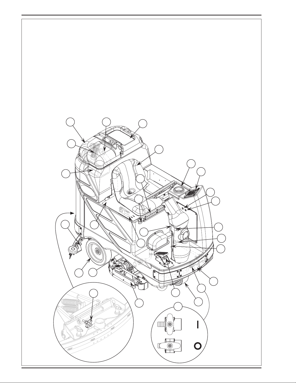
KNOW YOUR MACHINE
As you read this manual, you will occasionally run across a bold number or letter in parentheses - example: (2). These numbers refer to an item shown on
these pages unless otherwise noted. Refer back to these pages whenever necessary to pinpoint the location of an item mentioned in the text. NOTE: Refer
to the service manual for detailed explanations of each item illustrated on the next 2 pages.
1 Recovery Tank Cover
2 Solution Tank Fill Cover
3 Operator’s Seat
4 Solution Tank Drain Hose
5 Steering Wheel Tilt Adjust Knob
6 Brake Pedal / Parking Brake
7 Solution Flow Control Lever
8 Drive Pedal, Directional/Speed
9 Hopper (cylindrical models only)
10 Drive and Steer Wheel
11 Wheel Drive Circuit Breaker
12 Control Circuit Circuit Breaker
13 Emergency Stop Switch / Battery Disconnect
14 Scrub Deck
15 Rear Wheel
16 Battery Compartment (under seat)
17 Recovery Tank Shutoff Float
18 Vacuum Motor Filter Housing
19 Squeegee Assembly
20 Solution Filter
21 Recovery Tank Drain Hose
22 Machine Battery Connector
23 Control Panel
24 Squeegee Tilt Adjust Knob
25 Operator Seat Adjustment Lever
26 ECO Solution™
27 Strainer Basket
A-4 - FORM NO. 56041813 - BR850S SBG SPECIAL
8/2009
Page 5

ENGLISH / A-5
A
B
C
D
E
F
G
H
I
J
K
L
M
N
O
P
Q
R
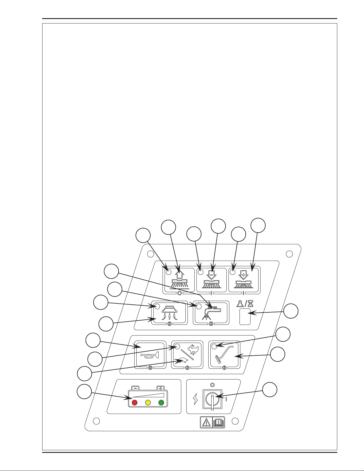
CONTROL PANEL
A Scrub OFF Indicator
B Scrub OFF Switch
C Scrub Pressure Decrease Indicator
D Scrub Pressure Decrease Switch
E Scrub Pressure Increase Indicator
F Scrub Pressure Increase Switch
G Scrub Pressure / Hourmeter Display
H Wand Switch Indicator
I Wand Switch
J Key Switch
K Battery Condition Indicator
L Speed Select Switch
M Speed Select Indicator
N Horn Switch
O Vacuum Switch
P Vacuum System Indicator
Q Solution System Indicator
R Solution Switch
8/2009
FORM NO. 56041813 - BR850S SBG SPECIAL - A-5
Page 6
A-6 / ENGLISH
415 Ah, 20 Hr. Rate
revised 1/2013
DESCRIPTION OF THE BATTERY CONDITION INDICATORS
The battery condition indicator (K) consists of three lights, a green, a yellow, and a red. The voltage indication will change based on the cutoff level (standard
or alternate) selected in the control unit. The battery voltage ranges for the various indications are listed below:
Standard Alternate
Green 34.00+ 34.50+
Green & Yellow 33.00-33.99 34.00-34.49
Yellow 32.00-32.99 33.50-33.99
Yellow & Red 31.50-31.99 33.00-33.49
Red 31.00-31.49 32.50-32.99
Flashing Red/Cutoff <31.00 <32.50
NOTE: Refer to service manual for selection of alternate cut-off level. Once the low voltage cutout level has been reached (fl ashing red indicator) the
batteries must be FULLY recharged to reset the battery condition indicator. The scrub system will not function until the indicator has been reset.
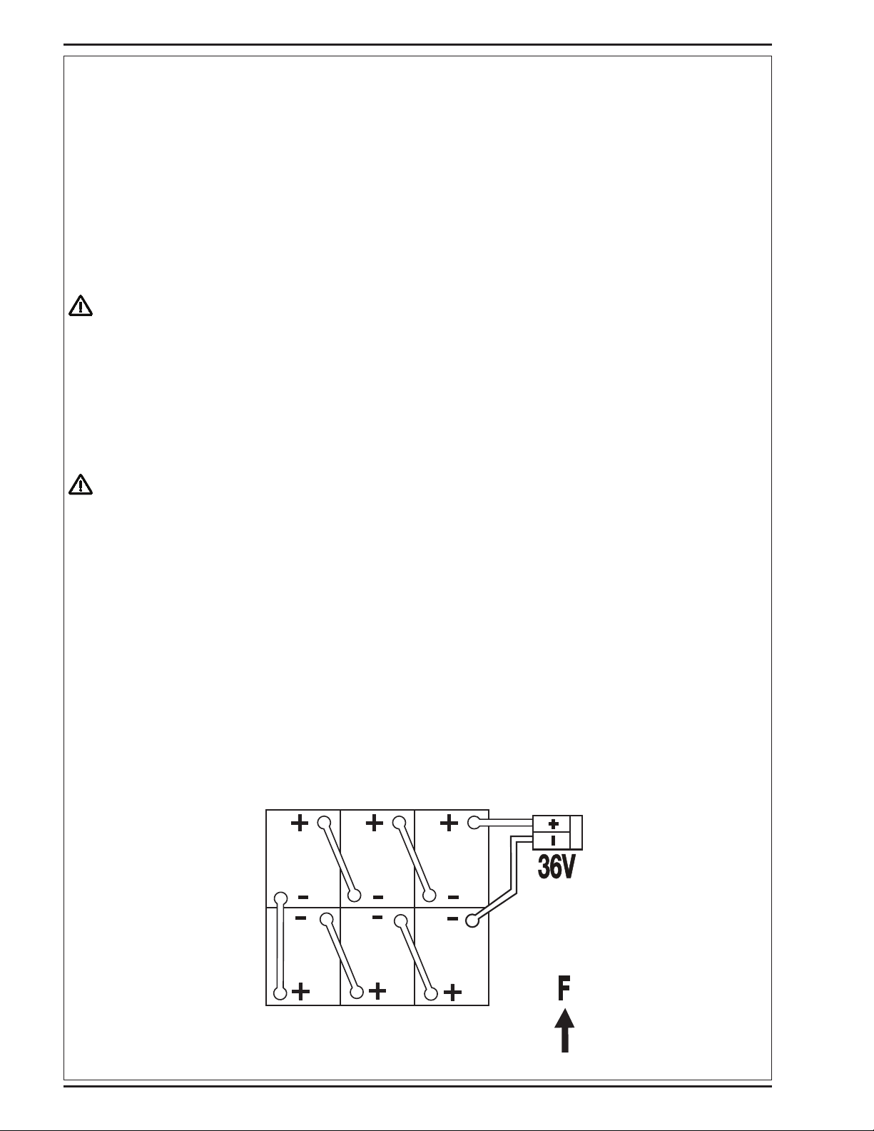
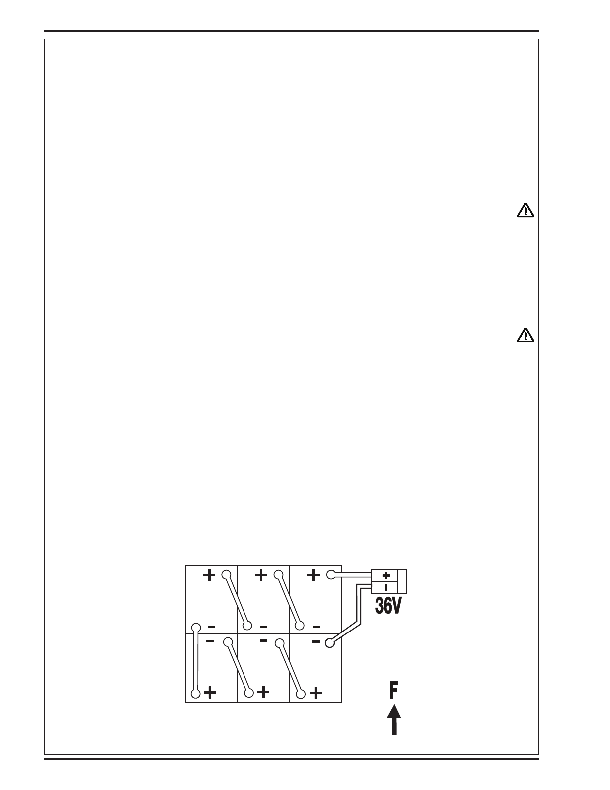
INSTALL THE BATTERIES
WARNING!
Use extreme caution when working with batteries. Sulfuric acid in batteries can cause severe injury if allowed to contact the skin
or eyes. Explosive hydrogen gas is vented from inside the batteries through openings in the battery caps. This gas can be ignited
by any electrical arc, spark or fl ame.
When Servicing Batteries...
* Remove all jewelry.
* Do not smoke.
* Wear safety glasses, a rubber apron and rubber gloves.
* Work in a well-ventilated area.
* Do not allow tools to touch more than one battery terminal at a time.
CAUTION!
Electrical components in this machine can be severely damaged if the batteries are not installed and connected properly.
Batteries should be installed by Nilfi sk or by a qualifi ed electrician.
1 Turn the Key Switch (J) off (O) and remove the key. Then swing open the Battery Compartment Cover (16).
2 Using (2) people and an appropriate lifting strap, carefully lift the batteries into the compartment tray exactly as shown. Refer to decal 56380513 battery
cable layout.
3 See Figure 1. Install battery cables as shown and tighten the nuts on the battery terminals.
4 Install the battery boots and secure tightly to the battery cables with the supplied tie straps.
5 Connect the battery pack connector to the machine connector (22) and close the battery compartment cover.
When changing batteries or the charger, please contact your local authorized service center for correct battery, charger and
machine settings to prevent battery damage.
FIGURE 1
A-6 - FORM NO. 56041813 - BR850S SBG SPECIAL
8/2009
Page 7
revised 4/2014
ENGLISH / A-7
INSTALL THE BRUSHES (DISC SYSTEM)
CAUTION!
Turn the key switch off (O) and remove the key, before changing the brushes, and before opening any access panels.
1 Make sure the Key Switch (J) is off (O). To access the brushes, remove both side skirt assemblies. Note: The skirts are held in place by two large Knobs, loosen these
knobs and slide the skirt assemblies off of the Scrub Deck.
2 To mount the brushes (or pad holders) align the lugs on the brush with the holes on the mounting plate and turn to lock in place (turn outside edge of brush towards front
of machine).
INSTALL THE BRUSHES (CYLINDRICAL SYSTEM)
CAUTION!
Turn the key switch off (O) and remove the key, before changing the brushes, and before opening any access panels.
1 Make sure the Key Switch (J) is off (O). To access the brushes, swing both side skirt assemblies open. Note: The skirts are held in place by a large cotter pin on each
side, remove the pins and swing the skirt assemblies out of the way. Loosen the black knobs (one on each side) on top of the idler assemblies and remove the idler
assemblies. Slide the brush into the housing, lift slightly, push and turn until it seats. Re-install the idler assemblies, close the skirt assemblies and secure with cotter pins.
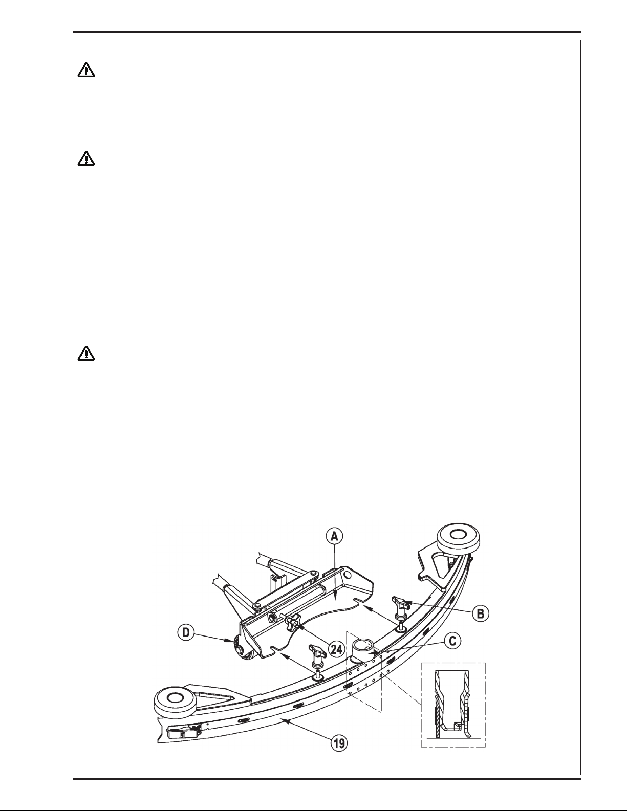
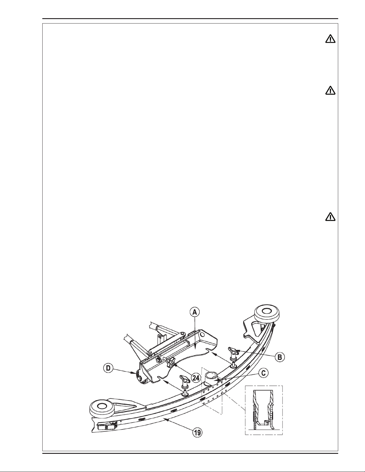
INSTALL THE SQUEEGEE
1 Make sure the Squeegee (19) is up (O) and the Key Switch (J) is off (O). Hold the squeegee tool so that the curved ends point forward, then slide the
squeegee tool onto the Mount (A) (See Figure 2).
2 Hand tighten the Thumb Nuts (B) and then connect the vacuum hose to the Squeegee Tube (C) (vacuum hose should loop to the right).
3 Lower the squeegee, move the machine ahead slightly and adjust the squeegee tilt and height using the Squeegee Tilt Adjust Knob (24) and Squeegee
Height Wheels (D) so that the rear squeegee blade touches the fl oor evenly across its entire width and is bent over slightly as shown in the squeegee
cross section.
FILL THE SOLUTION TANK
Read the cleaning chemical label and fi gure the proper amount of chemical to mix for a tank that holds 40 US gallons (151 liters).
Open the Solution Tank Cover (2), then fi ll the tank 1/3 full of water, add the cleaning chemical, then fi ll the tank to 7.62cm (3 inches) from the top of the tank
opening (fi ll to bottom of the wall in tank opening).
CAUTION!
Use only low-foaming, non-fl ammable liquid detergents intended for automatic scrubber machine applications. Water
temperature should not exceed 130 degrees Fahrenheit (54.4 degrees Celsius).
FIGURE 2
8/2009
FORM NO. 56041813 - BR850S SBG SPECIAL - A-7
Page 8

A-8 / ENGLISH
revised 1/2010
OPERATING THE MACHINE
WARNING!
Be sure you understand the operator controls and their functions.
While on ramps or inclines, avoid sudden stops when loaded. Avoid abrupt sharp turns. Use low speed down hills.
To Scrub...
Follow the instructions in preparing the machine for use section of this manual.
1 While seated on the machine, adjust the seat and steering wheel to a comfortable operating position using the adjustment controls (25) and (5).
2 Turn the Master Key Switch (J) ON (I). This will display the control panel indicator lights, reference the Battery Condition Indicator (K) and Hour Meter
(G).
3 Release the Parking Brake (6). To transport the machine to the work area, apply even pressure with your foot on the front of the Drive Pedal (8) to go
forward or the rear of the pedal for reverse. Vary the pressure on the foot pedal to obtain the desired speed.
4 Adjust the Solution Flow Control Valve Lever (7) to about 1/4 to 1/3 open position.
The fl ow rate can be changed to allow variable solution fl ow for different types of fl oors to be scrubbed. Example: A rough or absorbent fl oor surface
such as unfi nished concrete, will require more solution than a smooth fi nished fl oor.
NOTE: For a consistent reduced fl ow of solution; open the Solution Flow Control Valve Lever (7) all the way and then turn ON the ECO Solution™
Valve (26). When the lever is in the “OFF” position; the machine operates conventionally; solution fl ow is determined by the Solution Flow Control Lever
(7). When the lever is in the “ON” position; solution fl ow is controlled automatically. The Solution Flow Control Lever (7) should not be shut off, but is
otherwise inactive. Make sure that the lever for Valve (26) is all the way ON or all the way OFF, never in between. If more solution is needed, turn OFF
the ECO Solution™ Valve (26) and adjust the solution fl ow with the Solution Flow Control Valve Lever (7).
NOTE: The solution and vacuum systems are automatically activated when the Scrub Pressure Decrease Switch (D) or the Scrub Pressure Increase
Switch (F) is pressed. No further action is required. Any individual system can be turned OFF or back ON by simply pressing its switch at any time
during scrubbing.
5 Press and hold the Solution Switch (R) for 5 seconds to pre-wet the fl oor. NOTE: This must be done prior to pressing the Scrub ON Switch (F).
6 When the Scrub Pressure Decrease Switch (D) or the Scrub Pressure Increase Switch (F) is selected, the brushes and squeegee are automatically
lowered to the fl oor. The machine’s scrub brush rotation, solution system fl ow and vacuum starts when the Drive Pedal (8) is activated. Note: When
operating the machine in reverse, only the brushes will rotate, the solution is automatically shut off to conserve usage.
7 Begin scrubbing by driving the machine forward in a straight line at a normal walking speed and overlap each path by 2-3 inches (50-75 mm). Adjust
when necessary the machine speed and solution fl ow according to the condition of the
fl oor.
CAUTION!
To avoid damaging the fl oor, keep the machine moving while the brushes are turning.
8 When scrubbing, check behind the machine occasionally to see that all of the waste water is being picked up. If there is water trailing the machine, you
may be dispensing too much solution, the recovery tank may be full, or the squeegee tool may require adjustment.
9 For extremely dirty fl oors, a one-pass scrubbing operation may not be satisfactory and a “double-scrub” operation may be required. This operation is
the same as a one-pass scrubbing except on the fi rst pass the squeegee is in the up position (press the Vacuum Switch (O) to raise the squeegee).
This allows the cleaning solution to remain on the fl oor to work longer. The fi nal pass is made over the same area, with the squeegee lowered to pick
up the accumulated solution.
10 The recovery tank has an automatic fl oat shut-off to prevent solution from entering the vacuum system when the recovery tank is full. When the fl oat
shut-off is activated, the control system will shut down the scrub, vacuum and solution systems. The Scrub Pressure / Hourmeter Display (G) will
display “FULL”. To clear the display, press the Scrub OFF Switch (B), Scrub Pressure Decrease Switch (D), Scrub Pressure Increase Switch (F) or the
Vacuum Switch (O). When the fl oat closes, the recovery tank must be emptied. The machine will not pick up water with the fl oat closed. NOTE: If
the control repeatedly gives a full indication when the tank is not full, the automatic shut-off feature can be disabled, have a qualifi ed service technician
refer to the service manual to perform this function.
11 When the operator wants to stop scrubbing or the recovery tank is full, press the Scrub OFF Switch (B) once. This will automatically stop the scrub
brushes and solution fl ow and the scrub deck will raise UP. NOTE: the vacuum/squeegee system will not be turned off when the switch is only pressed
once, this is to allow any remaining water to be picked up without turning the vacuum back on. Press the switch a second time and the squeegee will
raise and the vacuum will stop after a 10 second delay.
12 Drive the machine to a designated waste water “DISPOSAL SITE” and empty the recovery tank. To empty, pull the Drain Hose (21) from its rear
storage area, then remove the plug (hold the end of the hose above the water level in the tank to avoid sudden, uncontrolled fl ow of waste water). Refi ll
the solution tank and continue scrubbing.
WET VACUUMING
Steps to follow in fi tting the machine with optional attachments for wet vacuuming.
1 Disconnect the recovery hose from the squeegee. Connect the coupler and hose from the wand kit to the recovery hose.
2 Attach suitable wet pick-up tools to the hose. (An optional Wand Kit PN56314307 is available from Nilfi sk).
3 Turn the Master Key Switch (J) ON, next press the Wand Switch (I). The vacuum motor and pump will run continuously until the switch is pressed
again to turn them OFF. NOTE: If the control repeatedly gives a full indication when the tank is not full, the automatic shut-off feature can be disabled,
have a qualifi ed service technician perform this function.
A-8 - FORM NO. 56041813 - BR850S SBG SPECIAL
8/2009
Page 9

revised 1/2010
ENGLISH / A-9
AFTER USE
1 When fi nished scrubbing, press the Scrub Off Switch (B) twice, this will automatically raise, retract and stop all the machine systems (brush, squeegee,
vacuum and solution). Then drive the machine to a service area for daily maintenance and review of other needed service up keep.
2 To empty the solution tank, remove the Solution Drain Hose (4) from its storage clamp. Direct the hose to a designated “DISPOSAL SITE” and remove
the plug. Rinse the tank with clean water.
3 To empty the recovery tank, pull the Recovery Tank Drain Hose (21) from its storage area. Direct the hose to a designated “DISPOSAL SITE” and
remove the plug (hold the end of the hose above the water level in the tank to avoid sudden, uncontrolled fl ow of waste water). Rinse the tank with
clean water.
4 Remove the brushes or pad holders. Rinse the brushes or pads in warm water and hang up to dry.
5 Remove the squeegee, rinse it with warm water and re-install on mount.
6 Remove the hopper on cylindrical systems and clean thoroughly. Remove from either side of the machine by opening the skirt and tilting the hopper up
and away from housing, then pull out.
7 Check the maintenance schedule below and perform any required maintenance before storage
MAINTENANCE SCHEDULE
MAINTENANCE ITEM Daily Weekly Monthly Yearly
Charge Batteries X
Check/Clean Tanks & Hoses X
Check/Clean/Rotate the Brushes/Pads X
Check/Clean the Squeegee X
Check/Clean Vacuum Shut-Off Float X
Check/Clean the vacuum motor foam fi lter(s) X
Empty/Clean Strainer Basket in Recovery Tank X
Clean Hopper on Cylindrical System X
Check Each Battery Cell(s) Water Level X
Inspect Scrub Housing Skirts X
Inspect and clean Solution Filter X
Check Foot/ Parking Brake For Wear & Adjustment X
Clean Solution Trough on Cylindrical System X
Lubrication - Grease Fittings X
* Check Carbon Brushes X
* Have Nilfi sk check the vacuum motor carbon motor brushes once a year or after 300 operating hours. The brush and drive motor carbon brushes check
every 500 hours or once a year.
NOTE: Refer to the Service Manual for more detail on maintenance and service repairs.
8 Store the machine indoors in a clean dry place. Keep from freezing. Leave the tanks open to air them out.
9 Turn the Master Key Switch (J) OFF (O) and remove the key.
LUBRICATING THE MACHINE
Once a month, pump a small amount of grease into each grease fi tting on the machine until grease seeps out around the bearings.
Grease fi tting locations are:
• Squeegee Caster Wheel Axle
• Steering Wheel Shaft Universal joint
Once a month, apply light machine oil to lubricate the:
• Steering Chain
• General Pivot Points For the Squeegee, Brush Linkage and Side Skirts
• Squeegee mount angle adjustment knob threads
8/2009
FORM NO. 56041813 - BR850S SBG SPECIAL - A-9
Page 10

A-10 / ENGLISH
CHARGING THE BATTERIES
Charge the batteries each time the machine is used, or whenever the Battery Condition Meter (K) is showing a yellow , red or fl ashing red indicator light(s).
To Charge the Batteries...
1 Depress the Battery Disconnect (13).
2 Open the Battery Compartment Cover (16) to provide proper ventilation.
3 Push the connector from the charger into the Battery Connector (22).
4 Follow the instructions on the battery charger.
5 Check the fl uid level in all battery cells after charging the batteries. Add distilled water, if necessary, to bring the fl uid level up to the bottom of the fi ller
tubes.
WARNING!
Do not fi ll the batteries before charging.
Only charge batteries in a well-ventilated area.
Do not smoke while servicing the batteries.
CAUTION!
To avoid damage to fl oor surfaces, always wipe water and acid from the top of the batteries after charging.
CHECKING THE BATTERY ELECTROLYTE LEVEL
Check the electrolyte level of the batteries at least once a week.
After charging the batteries, remove the vent caps and check the electrolyte level in each battery cell. Use distilled water to fi ll the batteries to the bottom of
the fi ller tube.
Do not over-fi ll the batteries!
CAUTION!
Acid can spill onto the fl oor if the batteries are overfi lled.
Tighten the vent caps. If there is acid on the batteries, wash the tops of the batteries with a solution of baking soda and water (2 tablespoons of baking soda
to 1 quart of water).
A-10 - FORM NO. 56041813 - BR850S SBG SPECIAL
8/2009
Page 11

ENGLISH / A-11
SQUEEGEE MAINTENANCE
If the squeegee leaves narrow streaks or water, the blades may be dirty or damaged. Remove the squeegee, rinse it under warm water and inspect the
blades. Reverse or replace the blades if they are cut, torn, wavy or worn.
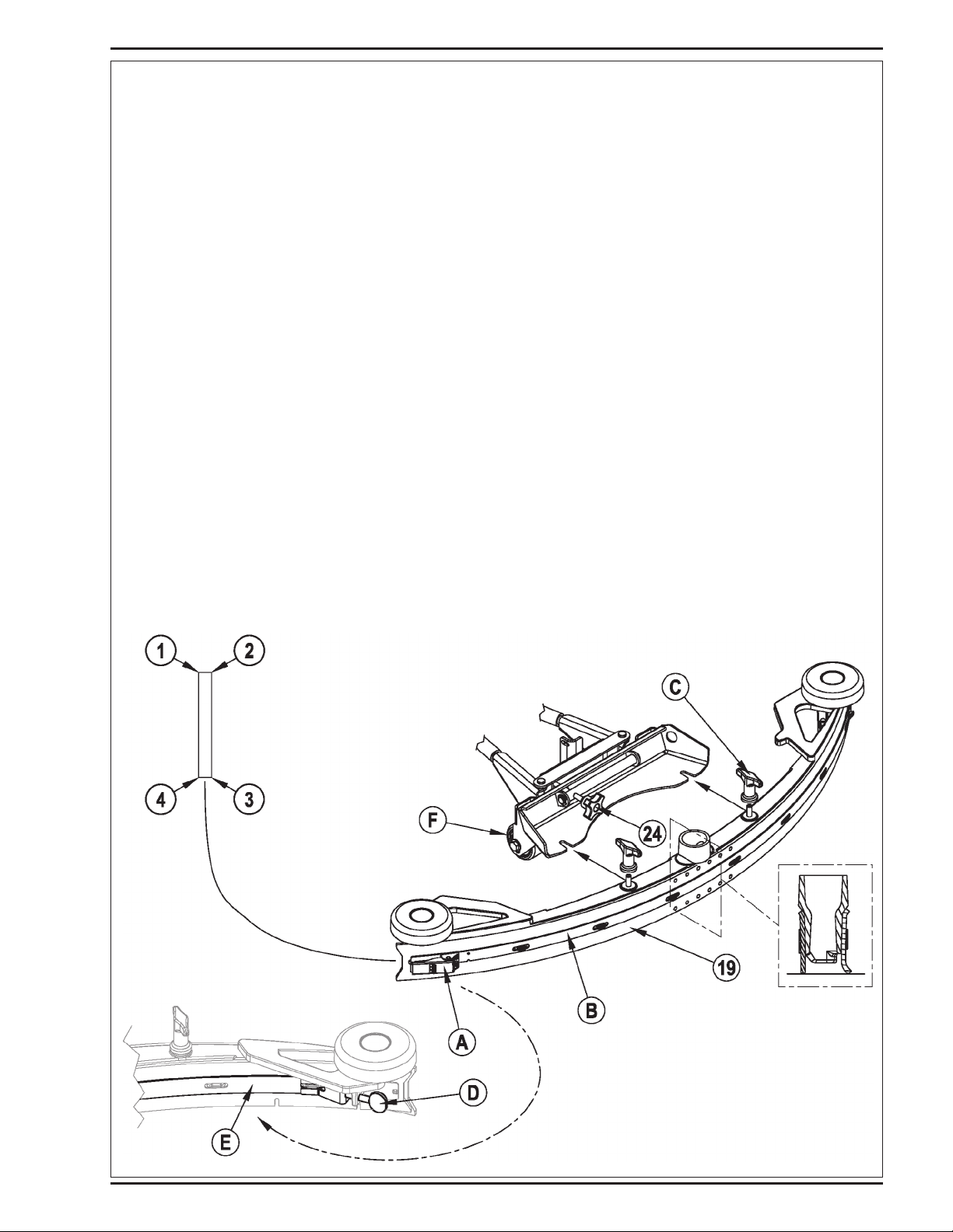
To Reverse or Replace the Rear Squeegee Wiping Blade...
1 See Figure 3. Raise the squeegee tool off the fl oor, then unsnap the Rear Squeegee Blade Removal Latch (A) on the squeegee tool.
2 Remove the Tension Strap (B).
3 Slip the rear blade off the alignment pins.
4 The squeegee blade has 4 working edges. Turn the blade so a clean, undamaged edge points toward the front of the machine. Replace the blade if all
4 edges are nicked, torn or worn to a large radius.
5 Install the blade, following the steps in reverse order and adjust the squeegee tilt.
To Reverse or Replace the Front Squeegee Blade...
1 Raise the squeegee tool off the fl oor, then loosen the (2) Thumb Nuts (C) on top of the squeegee and remove the squeegee tool from the mount.
2 Loosen the Front Squeegee Blade Removal Thumb Nut (D), then remove Tension Strap (E) and blade.
3 The squeegee blade has 4 working edges. Turn the blade so a clean, undamaged edge points toward the front of the machine. Replace the blade if all
4 edges are nicked, torn or worn to a large radius.
4 Install the blade, following the steps in reverse order and adjust the squeegee tilt.
SQUEEGEE ADJUSTMENT
There are two squeegee tool adjustments possible, angle and height.
Adjust the squeegee angle whenever a blade is reversed or replaced, or if the squeegee is not wiping the fl oor dry.
1 Park the machine on a fl at, even surface and lower the squeegee. Then drive the machine forward enough to have the squeegee blades fold over to
the rear.
2 Adjust the squeegee tilt and height using the Squeegee Tilt Adjust Knob (24) and Squeegee Height Wheel (F) so that the rear squeegee blade touches
the fl oor evenly across its entire width and is bent over slightly as shown in the squeegee cross section.
FIGURE 3
8/2009
FORM NO. 56041813 - BR850S SBG SPECIAL - A-11
Page 12

A-12 / ENGLISH
revised 4/2014
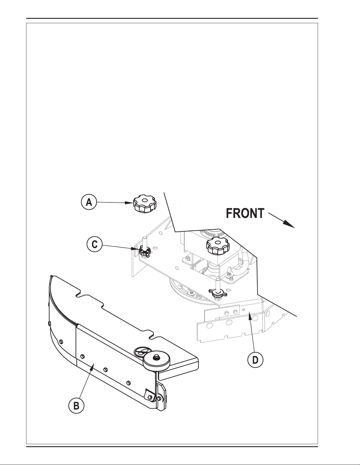
SIDE SKIRT MAINTENANCE (DISC SYSTEM)
The side skirt’s function is to channel the waste water to the squeegee, helping contain the water within the machines cleaning path. During normal use the
blades will wear in time. The operator will notice a small amount of water leaking out underneath the side skirts. A height adjustment can easily be made to
lower the blades so that all the water can be pick-up by the squeegee.
To reverse or replace the scrub system side skirt(s) ...
1 See Figure 4. Loosen the (2) side skirt Retainer Knobs (A) (2 per side) and pull the Skirt Assemblies (B) off from the scrub deck.
2 Remove all the hardware that holds the blades to the skirt housings.
3 Replace the blades as a set if they are nicked, torn or worn beyond their ability to be adjusted.
4 Reinstall the skirt housing assemblies onto the machine and adjust the blade for proper contact to the fl oor when the brush deck is placed in the scrub
position.
SIDE SKIRT HEIGHT ADJUSTMENT (DISC SYSTEM)
1 The side skirt housing knob retainer screw studs have leveling Adjuster Collars (C), that are to be raised or lowered to compensate for blade wear.
2 To adjust, remove the Skirt Assemblies (B) from the Scrub Deck (D) to access the Adjuster Collars (C). Adjustment Tip: The skirts Retainer Knobs (A)
can be loosened with skirts left on and the Adjuster Collars (C) rotated by reaching under the skirt housing.
3 Turn the Adjuster Collars (C) (Up or Down) to where the blades just fold over enough when scrubbing that all the waste water is contained inside the
skirting. Note: Make small adjustments to obtain good blade wiping. Do not lower the blades too much to where they fold over excessively and cause
unneeded blade wear.
FIGURE 4
A-12 - FORM NO. 56041813 - BR850S SBG SPECIAL
8/2009
Page 13

revised 4/2014
ENGLISH / A-13
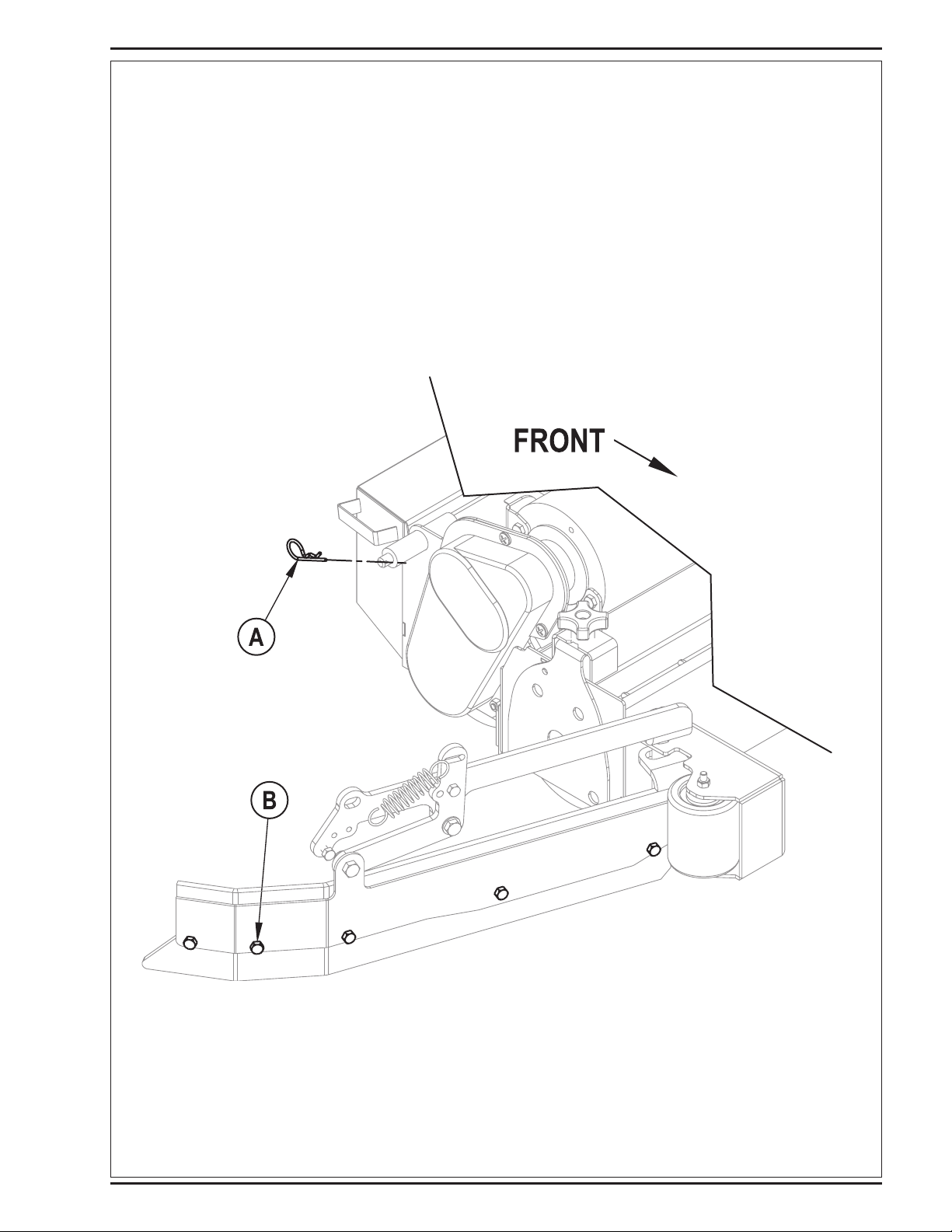
SIDE SKIRT MAINTENANCE (CYLINDRICAL SYSTEM)
The side skirts function is to channel the waste water to the squeegee, helping contain the water within the machines cleaning path. During normal use the
blades will wear in time. The operator will notice a small amount of water leaking out underneath the side skirts. Skirt height adjustment is automatic on this
system. The skirt assemblies should move up and down freely for proper operation.
To replace the scrub system side skirt(s) ...
1 See Figure 5. Remove the (2) (A) Cotter Pins and swing the Skirt Assemblies open. Remove the (B) Screws and Nuts, remove the Skirts and replace.
FIGURE 5
8/2009
FORM NO. 56041813 - BR850S SBG SPECIAL - A-13
Page 14

A-14 / ENGLISH
GENERAL MACHINE TROUBLESHOOTING
Problem Possible Cause Remedy
Poor water pick-up Worn or torn squeegee blades Reverse or replace
Squeegee out of adjustment Adjust so blades touch fl oor evenly
across entire width
Recovery tank full Empty recovery tank
Recovery tank drain hose leak Secure drain hose cap or replace
Recovery tank cover gasket leak Replace gasket / Seat cover properly
Debris caught in squeegee Clean squeegee tool
Vacuum hose clogged Remove debris
Using too much solution Adjust solution control valves
Foam fi lter cover not seated Seat cover properly
Poor scrubbing performance Worn brush or pad Rotate or replace brushes
Wrong brush or pad type Consult Nilfi sk
Wrong cleaning chemical Consult Nilfi sk
Moving machine too fast Slow down
Not using enough solution Adjust solution control valves
Inadequate solution fl ow
or no solution
Machine does not run Emergency stop switch tripped Reconnect battery connectors
No FWD/REV wheel drive Drive system speed contoller Check error fault codes
Vacuum shuts off and display shows
“FULL” when recovery tank is not full
Poor Sweeping Performance
(Cylindrical System)
Solution tank empty Fill solution tank
Solution lines, valves, fi lter or trough
clogged
Solution control valves not open Adjust solution control valves
Solution solenoid valve Clean or replace valve
Operator seat safety switch Check for open circuit and replace
Main system controller Check error fault codes
Tripped 10 Amp circuit breaker Check for electrical short circuit & reset
Tripped 70 Amp circuit breaker
Emergency stop switch tripped Reconnect battery connectors
Plugged squeegee hose Clear debris
Vacuuming large amounts of water
at a high travel speed
Hopper Full Empty and clean hopper
Brushes worn Replace brushes
Bristles have taken a set Rotate brushes
Flush lines, trough and clean solution fi lter
(see service manual)
(see service manual)
Check for drive motor overload
Slow down or disable auto shut-off feature
(see service manual)
A-14 - FORM NO. 56041813 - BR850S SBG SPECIAL
8/2009
Page 15

revised 4/2014
TECHNICAL SPECIFICATIONS (as installed and tested on the unit)
Model BR850S SBG Special
Model No. 56390926 / 56383899
Voltage, Batteries V 36V
Battery Capacity Ah 415
Protection Grade IPX3
Sound Power Level
(IEC 60335-2-72: 2002 Amend. 1:2005, ISO 3744)
Gross Weight lbs / kg 1,732 / 785
Maximum Wheel Floor Loading (center front) psi / N/mm
Maximum Wheel Floor Loading (right rear) psi / N/mm
Maximum Wheel Floor Loading (left rear) psi / N/mm
Vibrations at the Hand Controls (ISO 5349-1) m/s
Vibrations at the Seat (EN 1032) m/s
Gradeability
Transport 20% (11.5o)
Cleaning 8% (4.6o)
dB(A)/20μPa 70
2
2
2
2
2
98 / .68
53 / .36
70 / .48
1.12m/s
0.35m/s
2
2
ENGLISH / A-15
8/2009
FORM NO. 56041813 - BR850S SBG SPECIAL - A-15
Page 16

B-2 / ﺔﻴﺑﺮﻌﻟﺍ
revised 12/2014
ﺕﺎﻳﻮﺘﺤﻤﻟﺍ ﻝﻭﺪﺟ
ﺔﺤﻔﺼﻟﺍ
2-ﺃ .............................................................................................. ﺔﻣﺪﻘﻣ
3-ﺃ ...........................................................................ﺕﺍﺮﻳﺬﺤﺘﻟﺍﻭ ﺕﺎﻬﻴﺒﻨﺘﻟﺍ
4-ﺃ ............................................................................. ﻙﺯﺎﻬﺟ ﻰﻠﻋ ﻑﺮﻌﺗ
5-ﺃ ...................................................................................... ﻢﻜﺤﺘﻟﺍ ﺔﺣﻮﻟ
ﻡﺍﺪﺨﺘﺳﻼﻟ ﺯﺎﻬﺠﻟﺍ ﺩﺍﺪﻋﺇ
6-ﺃ ............................................................................... ﺕﺎﻳﺭﺎﻄﺒﻟﺍ ﺐﻴﻛﺮﺗ
7-ﺃ ....................................................................................ﺵَﺮُﻔﻟﺍ ﺐﻴﻛﺮﺗ
7-ﺃ ..................................................................................ﺔﺣﺎﱠﺴﻤﻟﺍ ﺐﻴﻛﺮﺗ
7-ﺃ ...................................................................ﻒﻴﻈﻨﺘﻟﺍ ﻝﻮﻠﺤﻣ ﻥﺍﺰﺧ ﺔﺌﺒﻌﺗ
8-ﺃ .................................................................................... ﺯﺎﻬﺠﻟﺍ ﻞﻴﻐﺸﺗ
8-ﺃ .............................................................................. ﺔﺤﺴﻤﻤﻟﺎﺑ ﻒﻴﻈﻨﺘﻟﺍ
8-ﺃ ......................................................................ﺔﺴﻨﻜﻤﻟﺎﺑ ﺐﻁﺮﻟﺍ ﻒﻴﻈﻨﺘﻟﺍ
9-ﺃ .................................................................................... ﻡﺍﺪﺨﺘﺳﻻﺍ ﺪﻌﺑ
9-ﺃ ................................................................................... ﺔﻧﺎﻴﺼﻟﺍ ﻝﻭﺪﺟ
9-ﺃ .................................................................................... ﺯﺎﻬﺠﻟﺍ ﻢﻴﺤﺸﺗ
10-ﺃ ............................................................................... ﺕﺎﻳﺭﺎﻄﺒﻟﺍ ﻦﺤﺷ
10-ﺃ .......................................................... ﺔﻳﺭﺎﻄﺒﻟﺎﺑ ﻝﺭﺎﻬﻜﻟﺍ ﻯﻮﺘﺴﻣ ﺺﺤﻓ
11-ﺃ ................................................................................ ﺔﺣﺎﱠﺴﻤﻟﺍ ﺔﻧﺎﻴﺻ
11-ﺃ ................................................................................. ﺔﺣﺎﱠﺴﻤﻟﺍ ﻂﺒﺿ
13-ﺃ – 12-ﺃ ............................................................. ﺔﻴﺒﻧﺎﺠﻟﺍ ﺔﻴﺷﺎﺤﻟﺍ ﺔﻧﺎﻴﺻ
14-ﺃ .............................................................. ﺎﻬﺣﻼﺻﺇﻭ ﻝﺎﻄﻋﻷﺍ ﻑﺎﺸﻜﺘﺳﺍ
15-ﺃ .............................................................................. ﺔﻴﻨﻔﻟﺍ ﺕﺎﻔﺻﺍﻮﻤﻟﺍ
ﺔﻣﺪﻘﻣ
.ﺯﺎﻬﺠﻟﺍ ﻞﻴﻐﺸﺗ ﻞﺒﻗ ﻞﻣﺎﻜﻟﺎﺑ ﻞﻴﻟﺪﻟﺍ ﺓءﺍﺮﻗ ﺐﺠﻳ .ﺔﻴﺿﺭﻷﺍ ﻒﻴﻈﻨﺘﻟ Nilfisk ﺔﺤﺴﻤﻣ ﻦﻣ ﺓﺩﺎﻔﺘﺳﺍ ﻰﻠﻋﺃ ﻖﻴﻘﺤﺗ ﻰﻠﻋ ﻞﻴﻟﺪﻟﺍ ﺍﺬﻫ ﻙﺪﻋﺎﺴﻴﺳ
.5-ﺃ ﻰﻟﺇ 4-ﺃ ﺕﺎﺤﻔﺼﻟﺍ ﻲﻓ ﺩﻮﺟﻮﻤﻟﺍ ﻢﺳﺮﻟﺍ ﻲﻓ ﺔﺤﺿﻮﻤﻟﺍ ﺮﺻﺎﻨﻌﻟﺍ ﺪﺣﺃ ﻰﻟﺇ ﺱﺍﻮﻗﻷﺍ ﻞﺧﺍﺩ ﺾﻳﺮﻋ ﻂﺨﺑ ﺔﺑﻮﺘﻜﻤﻟﺍ ﻡﺎﻗﺭﻷﺍ ﺮﻴﺸﺗ :ﺔﻈﺣﻼﻣ
.ﻂﻘﻓ ﻱﺭﺎﺠﺘﻟﺍ ﻡﺍﺪﺨﺘﺳﻼﻟ ﺺﺼﺨﻣ ﺞﺘﻨﻤﻟﺍ ﺍﺬﻫ
ﺔﻧﺎﻴﺼﻟﺍﻭ ﺭﺎﻴﻐﻟﺍ ﻊﻄﻗ
ﻊﻄﻗ ﻪﻴﻓ ﺮﻓﺍﻮﺘﺗ ﺎﻤﻛ ،ﻊﻨﺼﻤﻟﺍ ﻦﻣ ﻦﻳﺪﻤﺘﻌﻤﻟﺍﻭ ﻦﻴﻠﻫﺆﻤﻟﺍ ﻦﻴﻴﻨﻔﻟﺍ ﻦﻣ ﺔﺒﺨﻧ ﻢﻀﻳ ﻱﺬﻟﺍﻭ ،ﺓﺪﻤﺘﻌﻤﻟﺍ Nilfisk ﺔﻣﺪﺧ ﺰﻛﺍﺮﻣ ﺪﺣﺃ ،ﺓﺭﻭﺮﻀﻟﺍ ﺖﻀﺘﻗﺍ ﺍﺫﺇ ،ﺔﻧﺎﻴﺼﻟﺍﻭ ﺡﻼﺻﻹﺍ ﺕﺎﻴﻠﻤﻌﺑ ﻡﻮﻘﻳ ﻥﺃ ﺐﺠﻳ
.Nilfisk ﺔﻛﺮﺸﺑ ﺔﺻﺎﺨﻟﺍ ﺔﻴﻠﺻﻷﺍ ﺕﺎﻘﺤﻠﻤﻟﺍﻭ ﺭﺎﻴﻐﻟﺍ
ﺪﻨﻋ ﻙﺯﺎﻬﺠﺑ ﺹﺎﺨﻟﺍ ﻞﺴﻠﺴﻤﻟﺍ ﻢﻗﺭﻭ ﻞﻳﺩﻮﻤﻟﺍ ﺪﻳﺪﺤﺗ ﻰﺟﺮﻳ .ﺭﺎﻴﻐﻟﺍ ﻊﻄﻗ ﻭﺃ ﺔﻧﺎﻴﺼﻟﺍ ﻭﺃ ﺡﻼﺻﻹﺍ ﻰﻟﺇ ﺔﺟﺎﺤﻟﺍ ﺔﻟﺎﺣ ﻲﻓ ﻩﺎﻧﺩﺃ ﻪﻤﺳﺍ ﺩﺭﺍﻮﻟﺍ NILFISK DEALER ﻉﺯﻮﻤﺑ ﻝﺎﺼﺗﻻﺎﺑ ﻢﻗ
.ﻝﺎﺼﺗﻻﺍ
ﺕﻼﻳﺪﻌﺘﻟﺍ
ﻰﻠﻋ ﻝﻮﺼﺤﻟﺍ ﻥﻭﺩ ﻞﻴﻐﺸﺘﻟﺍ ﺔﻣﻼﺳﻭ ﺔﻌﺳ ﻰﻠﻋ ﺮﺛﺆﺗ ﻥﺃ ﺎﻬﻧﺄﺷ ﻦﻣ ﻲﺘﻟﺍﻭ ﻒﻴﻈﻨﺘﻟﺍ ﺯﺎﻬﺟ ﻰﻠﻋ ﺕﺎﻓﺎﺿﺇ ﻭﺃ ﺕﻼﻳﺪﻌﺗ ﺔﻳﺃ ءﺍﺮﺟﺈﺑ ﻡﺪﺨﺘﺴﻤﻟﺍ ﻭﺃ ﻞﻴﻤﻌﻟﺍ ﻡﻮﻘﻳ ﻥﺃ ﻝﺍﻮﺣﻷﺍ ﻦﻣ ﻝﺎﺣ ﻱﺄﺑ ﺯﻮﺠﻳ ﻻ
ﺙﺩﺍﻮﺣ ﻱﺃ ﻦﻋ ﺔﻠﻣﺎﻛ ﺔﻴﻟﻭﺆﺴﻤﻟﺍ ﻞﻴﻤﻌﻟﺍ ﻞﻤﺤﺘﻳﻭ ﺯﺎﻬﺠﻟﺍ ﻥﺎﻤﺿ ءﺎﻐﻟﺇ ﻲﻓ ﺐﺒﺴﺘﺘﺳ ﻖﺒﺴﻣ ﺢﻳﺮﺼﺗ ﻥﻭﺪﺑ ﺎﻫﺅﺍﺮﺟﺇ ﻢﺘﻳ ﺕﻼﻳﺪﻌﺗ ﺔﻳﺃﻭ .Nilfisk-Advance Inc.
ﺔﻛﺮﺷ ﻦﻣ ﻖﺒﺴﻣ ﻲﺑﺎﺘﻛ ﻥﺫﺇ
.ﻚﻟﺫ ﻰﻠﻋ ﺐﺗﺮﺘﺗ
ﺔﻴﻤﺴﺘﻟﺍ ﺡﻮﻟ
ﺔﻴﻟﺎﺘﻟﺍ ﺔﻴﻟﺎﺨﻟﺍ ﺔﺣﺎﺴﻤﻟﺍ ﻡﺪﺨﺘﺳﺍ .ﺯﺎﻬﺠﻟﺎﺑ ﺔﺻﺎﺨﻟﺍ ﺭﺎﻴﻐﻟﺍ ﻊﻄﻗ ﺐﻠﻁ ﺪﻨﻋ ﺕﺎﻧﺎﻴﺒﻟﺍ ﻩﺬﻫ ﻢﻳﺪﻘﺗ ﺐﺠﻳ .ﺯﺎﻬﺠﻟﺍ ﻰﻠﻋ ﺖﺒﺜﻤﻟﺍ ﺔﻴﻤﺴﺘﻟﺍ ﺡﻮﻟ ﻰﻠﻋ ﻙﺯﺎﻬﺠﺑ ﺹﺎﺨﻟﺍ ﻞﺴﻠﺴﻤﻟﺍ ﻢﻗﺭﻭ ﻞﻳﺩﻮﻤﻟﺍ ﻢﻗﺭ ﺮﻬﻈﻳ
.ًﻼﺒﻘﺘﺴﻣ ﺎﻬﻴﻟﺇ ﻉﻮﺟﺮﻠﻟ ﺯﺎﻬﺠﻟﺎﺑ ﺹﺎﺨﻟﺍ ﻞﺴﻠﺴﻤﻟﺍ ﻢﻗﺭﻭ ﻞﻳﺩﻮﻤﻟﺍ ﻢﻗﺭ ﺕﺎﻧﺎﻴﺑ ﻞﻴﺠﺴﺘﻟ
_______________________________________________________ ﻞﻳﺩﻮﻤﻟﺍ ﻢﻗﺭ
______________________________________________________ ﻞﺴﻠﺴﻤﻟﺍ ﻢﻗﺭ
ﺯﺎﻬﺠﻟﺍ ﻦﺤﺷ ﺓﻮﺒﻋ ﻚﻓ
ءﻼﻤﻌﻟﺍ ﺔﻣﺪﺧ ﻢﺴﻘﺑ ﻞﺼﺗﺍ .ﺎﻬﺼﺤﻓ ﻦﻜﻤﻳ ﻰﺘﺣ ﻦﺤﺸﻟﺍ ﺓﻮﺒﻌﺑ ﻆﻔﺘﺣﺍ ،ﺎًﺤﺿﺍﻭ ﻒﻠﺘﻟﺍ ﻥﺎﻛ ﺍﺫﺇ .ﺎﻤﻬﺑ ﻒﻠﺗ ﻱﺃ ﺩﻮﺟﻭ ﻡﺪﻋ ﻦﻣ ﺪﻛﺄﺘﻠﻟ ﺯﺎﻬﺠﻟﺍ ﻚﻟﺬﻛﻭ ﺍًﺪﻴﺟ ﻦﺤﺸﻟﺍ ﺓﻮﺒﻋ ﺺﺤﻓﺍ ،ﺯﺎﻬﺠﻟﺍ ﻡﻼﺘﺳﺍ ﺪﻨﻋ
.ﻦﺤﺸﻟﺍ ﺓﻮﺒﻋ ﻒﻠﺗ ﻦﻋ ﻍﻼﺑﻺﻟ ﺭﻮﻔﻟﺍ ﻰﻠﻋ Nilfisk ﺔﻛﺮﺸﺑ
.ﺔﻴﺿﺭﻷﺍ ﻰﻟﺇ ﻦﺤﺸﻟﺍ ﻕﻭﺪﻨﺻ ﺓﺪﻋﺎﻗ ﻦﻣ ﺯﺎﻬﺠﻟﺍ ﻞﻳﺰﻨﺘﻟ ﺔﻠﺋﺎﻣ ﺔﺿﺭﺎﻋ ﻡﺪﺨﺘﺳﺍ .ﺕﻼﺠﻌﻟﺍ ﺭﺍﻮﺠﺑ ﺓﺩﻮﺟﻮﻤﻟﺍ ﺔﻴﺒﺸﺨﻟﺍ ﻢﺋﺍﻮﻘﻟﺍ ﻉﺰﻧﺍﻭ ﺔﻴﻜﻴﺘﺳﻼﺒﻟﺍ ﺕﺎﻣﺎﻋﺪﻟﺍ ﻊﻄﻗﺍ ،ﺔﻴﻧﻮﺗﺮﻜﻟﺍ ﺓﻮﺒﻌﻟﺍ ﺔﻟﺍﺯﺇ ﺪﻌﺑ
B-2 - FORM NO. 56041813 - BR850S SBG SPECIAL
8/2009
Page 17

revised 12/2014
ﺔﻴﺑﺮﻌﻟﺍ / B-3
ﺕﺍﺮﻳﺬﺤﺘﻟﺍﻭ ﺕﺎﻬﻴﺒﻨﺘﻟﺍ
ﺯﻮﻣﺮﻟﺍ
ﺮﻴﺑﺍﺪﺘﻟﺍ ﺫﺎﺨﺗﺍﻭ ﺔﻳﺎﻨﻌﺑ ﺕﺎﻣﻮﻠﻌﻤﻟﺍ ﻩﺬﻫ ﺓءﺍﺮﻗ ﺎًﻤﺋﺍﺩ ﺐﺠﻳ .ﺓﺭﻮﻄﺧ ﻞﺜﻤﺗ ﻥﺃ ﻞﻤﺘﺤﻳ ﻲﺘﻟﺍ ﺕﻻﺎﺤﻟﺍﻭ ﻑﻭﺮﻈﻟﺍ ﺾﻌﺑ ﻰﻟﺇ ﺓﺭﺎﺷﻺﻟ ﺔﻴﻟﺎﺘﻟﺍ ﺯﻮﻣﺮﻟﺍ Nilfisk ﻡﺪﺨﺘﺴﺗ
.ﺕﺎﻜﻠﺘﻤﻤﻟﺍﻭ ﺹﺎﺨﺷﻷﺍ ﺔﻳﺎﻤﺤﻟ ﺔﻣﺯﻼﻟﺍ
!ﺮﻄﺧ
.ﺓﺎﻓﻮﻟﺍ ﺙﻭﺪﺣ ﻭﺃ ﺹﺎﺨﺷﻷﺍ ﻲﻓ ﺔﻐﻟﺎﺑ ﺕﺎﺑﺎﺻﺇ ﻉﻮﻗﻭ ﻰﻟﺇ ﻱﺩﺆﺗ ﺪﻗ ﻲﺘﻟﺍ ﺔﻠﺟﺎﻌﻟﺍ ﺮﻁﺎﺨﻤﻟﺍ ﻦﻣ ﺮﻳﺬﺤﺘﻠﻟ ﻡﺪﺨﺘﺴﻳ
!ﺮﻳﺬﺤﺗ
.ﺹﺎﺨﺷﻷﺍ ﻲﻓ ﺔﻐﻟﺎﺑ ﺔﺑﺎﺻﺇ ﻉﻮﻗﻭ ﻪﻴﻠﻋ ﺐﺗﺮﺘﻳ ﺪﻗ ﺎﻣ ﻒﻗﻮﻣ ﻮﺤﻧ ﻩﺎﺒﺘﻧﻻﺍ ﺏﺬﺠﻟ ﻡﺪﺨﺘﺴﻳ
!ﻪﻴﺒﻨﺗ
.ﺕﺎﻜﻠﺘﻤﻤﻟﺍ ﻦﻣ ﺎﻫﺮﻴﻏ ﻭﺃ ﺯﺎﻬﺠﻟﺍ ﻒﻠﺗ ﻭﺃ ﺹﺎﺨﺷﻷﺍ ﻲﻓ ﺔﻔﻴﻔﻁ ﺕﺎﺑﺎﺻﺇ ﻉﻮﻗﻭ ﻲﻓ ﺐﺒﺴﺘﻳ ﻥﺃ ﻦﻜﻤُﻳ ﺎﻣ ﻒﻗﻮﻣ ﻮﺤﻧ ﻩﺎﺒﺘﻧﻻﺍ ﺏﺬﺠﻟ ﻡﺪﺨﺘﺴﻳ
.ﻡﺍﺪﺨﺘﺳﻻﺍ ﻞﺒﻗ ﺔﻳﺎﻨﻌﺑ ﺕﺎﻤﻴﻠﻌﺘﻟﺍ ﺔﻓﺎﻛ ﺓءﺍﺮﻗ ﺐﺠﻳ
ﺔﻣﺎﻌﻟﺍ ﺔﻣﻼﺴﻟﺍ ﺕﺎﻤﻴﻠﻌﺗ
،ﻱﺭﺎﺠﺘﻟﺍ ﻡﺍﺪﺨﺘﺳﻼﻟ ﺺﺼﺨﻣ ﺯﺎﻬﺠﻟﺍ ﺍﺬﻫ .ﺔﻳﺪﺴﺠﻟﺍ ﺕﺎﺑﺎﺻﻹﺍ ﺾﻌﺑ ﻭﺃ ﺯﺎﻬﺠﻠﻟ ﺔﻠﻤﺘﺤﻤﻟﺍ ﺮﻁﺎﺨﻤﻟﺍ ﺾﻌﺑ ﻦﻣ ﻙﺮﻳﺬﺤﺘﻟ ﺕﺎﻬﻴﺒﻨﺘﻟﺍﻭ ﺕﺍﺮﻳﺬﺤﺘﻟﺍ ﺾﻌﺑ ﻦﻴﻤﻀﺗ ﻢﺘﻳ
.ﻦﻛﺎﺴﻤﻟﺍ ﻞﺧﺍﺩ ﺓﺩﺎﺘﻌﻤﻟﺍ ﻲﻟﺰﻨﻤﻟﺍ ﺮﻴﺑﺪﺘﻟﺍ ﺽﺍﺮﻏﺃ ﻲﻓ ﻪﻣﺍﺪﺨﺘﺳﺍ ﺯﻮﺠﻳ ﻻﻭ ،ﺐﺗﺎﻜﻤﻟﺍﻭ ﺔﻳﺭﺎﺠﺘﻟﺍ ﺕﻼﺤﻤﻟﺍﻭ ﻊﻧﺎﺼﻤﻟﺍﻭ ﺱﺭﺍﺪﻤﻟﺍﻭ ﻕﺩﺎﻨﻔﻟﺍ ﻲﻓ ﻝﺎﺜﻤﻟﺍ ﻞﻴﺒﺳ ﻰﻠﻋ
!ﺮﻳﺬﺤﺗ
.ﻚﻟﺬﻟ ﺍًﺪﻴﺟ ﻦﻴﻠﻫﺆﻣﻭ ﻦﻳﺪﻤﺘﻌﻣ ﺹﺎﺨﺷﺃ ﺔﻄﺳﺍﻮﺑ ﻻﺇ ﺯﺎﻬﺠﻟﺍ ﺍﺬﻫ ﻡﺍﺪﺨﺘﺳﺍ ﺯﻮﺠﻳ ﻻ *
ﺓﺮﺒﺨﻟﺍ ﻰﻟﺇ ﻥﻭﺮﻘﺘﻔﻳ ﻦﻤﻣ ﻭﺃ ﺔﻴﻠﻘﻌﻟﺍ ﻭﺃ ﺔﻴﺴﺤﻟﺍ ﻭﺃ ﺔﻳﺪﺴﺠﻟﺍ ﺔﻗﺎﻋﻹﺍ ﻱﻭﺫ ﻦﻣ (ﻝﺎﻔﻁﻷﺍ ﻚﻟﺫ ﻲﻓ ﺎﻤﺑ) ﺹﺎﺨﺷﻷﺍ ﺔﻄﺳﺍﻮﺑ ﻡﺍﺪﺨﺘﺳﻼﻟ ﺺﺼﺨﻣ ﺮﻴﻏ ﺯﺎﻬﺠﻟﺍ ﺍﺬﻫ *
.ﺔﻴﻓﺎﻜﻟﺍ ﺔﻓﺮﻌﻤﻟﺍﻭ
ﻝﻭﺰﻧ ءﺎﻨﺛﺃ ﺔﺌﻴﻄﺒﻟﺍ ﺔﻋﺮﺴﻟﺍ ﻡﺪﺨﺘﺳﺍ .ﺔﺘﻏﺎﺒﻤﻟﺍ ﺓﺩﺎﺤﻟﺍ ﺕﺎﻧﺍﺭﻭﺪﻟﺍ ﺐﻨﺠﺗ .ﺊﺟﺎﻔﻤﻟﺍ ﻑﻮﻗﻮﻟﺍ ﺐﻨﺠﺘﻓ ،ﺕﺍﺭﺪﺤﻨﻣ ﻭﺃ ﺔﻘﻟﺰﻨﻣ ﺕﺍﺮﻤﻣ ﻕﻮﻓ ﺯﺎﻬﺠﻟﺍ ﻡﺍﺪﺨﺘﺳﺍ ﺪﻨﻋ *
.ﺔﻘﻟﺰﻟﺍ ﺕﺍﺮﻤﻤﻟﺍ
.ﺯﺎﻬﺠﻠﻟ ﻱﺩﺎﻌﻟﺍ ﻞﻴﻐﺸﺘﻟﺍ ءﺎﻨﺛﺃ ﺭﺎﺠﻔﻧﻼﻟ ﺔﻠﺑﺎﻗ ﺓﺮﺨﺑﺃ ﺚﻌﺒﻨﺗ .ﻥﺎﺧﺩ ﻭﺃ ﺭﺮﺷ ﺎﻬﻨﻋ ﺭﺪﺼﻳ ﻲﺘﻟﺍ ﻭﺃ ﺔﻠﻌﺘﺸﻤﻟﺍ ﺩﺍﻮﻤﻟﺍ ﻦﻋ ﺍًﺪﻴﻌﺑ ﺕﺎﻳﺭﺎﻄﺒﻟﺎﺑ ﻆﻔﺘﺣﺍ *
ﺭﺩﺎﺼﻣ ﻦﻋ ﺍًﺪﻴﻌﺑ ،ﺔﻳﻮﻬﺘﻟﺍ ﺓﺪﻴﺟ ﻦﻛﺎﻣﻷﺍ ﻲﻓ ﻻﺇ ﺕﺎﻳﺭﺎﻄﺒﻟﺍ ﻦﺤﺸﺗ ﻻ .ﺭﺎﺠﻔﻧﻼﻟ ﺔﻴﻠﺑﺎﻘﻟﺍ ﺪﻳﺪﺷ ﻦﻴﺟﻭﺭﺪﻴﻬﻟﺍ ﺯﺎﻏ ﺙﺎﻌﺒﻧﺍ ﻲﻓ ﺕﺎﻳﺭﺎﻄﺒﻟﺍ ﻦﺤﺷ ﺔﻴﻠﻤﻋ ﺐﺒﺴﺘﺗ *
.ﺕﺎﻳﺭﺎﻄﺒﻟﺍ ﻦﺤﺷ ءﺎﻨﺛﺃ ﻦﻴﺧﺪﺘﻟﺍ ﻦﻋ ﻊﻨﺘﻣﺍ .ﻑﻮﺸﻜﻤﻟﺍ ﺐﻬﻠﻟﺍ
.ﺔﻴﺋﺎﺑﺮﻬﻜﻟﺍ ﺕﺎﻧﻮﻜﻤﻟﺍ ﻦﻣ ﺏﺮﻘﻟﺎﺑ ﻞﻤﻌﻟﺍ ءﺎﻨﺛﺃ ّﻲﻠُﺤﻟﺍ ﺔﻓﺎﻛ ﻉﺰﻧﺍ *
.ﺔﻴﺋﺎﺑﺮﻬﻜﻟﺍ ﺕﺎﻧﻮﻜﻤﻠﻟ ﺔﻧﺎﻴﺼﻟﺍ ﻝﺎﻤﻋﺃ ءﺍﺮﺟﺇ ﻞﺒﻗ ﺕﺎﻳﺭﺎﻄﺒﻟﺍ ﻞﺼﻓﺍﻭ (O) ﻑﺎﻘﻳﻹﺍ ﻊﺿﻭ ﻰﻟﺇ ﻞﻴﻐﺸﺘﻟﺍ ﺡﺎﺘﻔﻣ ﺭﺩﺃ *
.ﺯﺎﻬﺠﻟﺍ ﻢﻋﺪﻟ ﺔﻣﻼﺴﻟﺍ ﻞﻣﺍﻮﺣ ﻭﺃ ﺰﺟﺍﻮﺣ ﻊﺿﻭ ﻥﻭﺪﺑ ﺯﺎﻬﺠﻟﺍ ﻞﻔﺳﺃ ﻞﻤﻋ ﻱﺄﺑ ﺎًﻘﻠﻄﻣ ﻢﻘﺗ ﻻ *
ﺔﻠﺑﺎﻘﻟﺍ ﻞﺋﺍﻮﺴﻟﺍ ﺎﻬﺑ ﺪﺟﻮﺗ ﻲﺘﻟﺍ ﻖﻁﺎﻨﻤﻟﺍ ﻲﻓ ﺯﺎﻬﺠﻟﺍ ﻞﻴﻐﺸﺗ ﻭﺃ ﻞﺋﺍﻮﺴﻟﺍ ﻚﻠﺗ ﻦﻣ ﺏﺮﻘﻟﺎﺑ ﻭﺃ ﻕﻮﻓ ﺯﺎﻬﺠﻟﺍ ﻞﻴﻐﺸﺗ ﻭﺃ ،ﻝﺎﻌﺘﺷﻼﻟ ﺔﻠﺑﺎﻘﻟﺍ ﻒﻴﻈﻨﺘﻟﺍ ﻞﺋﺍﻮﺳ ﺵﺭ ﺐﻨﺠﺗ *
.ﻝﺎﻌﺘﺷﻼﻟ
.ءﺍﻮﻬﻟﺍ ﻂﻐﻀﺑ ﻞﻤﻌﺗ ﻒﻴﻈﻨﺗ ﺔﻨﻴﻛﺎﻣ ﻡﺍﺪﺨﺘﺳﺎﺑ ﺯﺎﻬﺠﻟﺍ ﺍﺬﻫ ﻒﻴﻈﻨﺗ ﺐﻨﺠﺗ *
ﺙﻭﺪﺣ ﻰﻟﺇ ﺵَﺮُﻔﻟﺍ ﻦﻣ ﻯﺮﺧﺃ ﻉﺍﻮﻧﺃ ﻡﺍﺪﺨﺘﺳﺍ ﻱﺩﺆﻳ ﺪﻘﻓ .ﺕﺎﻤﻴﻠﻌﺘﻟﺍ ﻞﻴﻟﺩ ﻲﻓ ﺓﺩﺪﺤﻤﻟﺍ ﺵﺮُﻔﻟﺍ ﻭﺃ ﺯﺎﻬﺠﻟﺍ ﻊﻣ ﺔﻘﻓﺮﻤﻟﺍ ﺵﺮُﻔﻟﺍ ﻑﻼﺧ ﺓﺎﺷﺮﻓ ﻱﺃ ﻡﺍﺪﺨﺘﺳﺍ ﻡﺪﻋ ﺐﺠﻳ *
.ﺔﻣﻼﺴﻟﺍ ﻲﻓ ﻞﻠﺧ
.ﺯﺎﻬﺠﻟﺍ ﺖﻴﺒﺜﺗ ﻭﺃ ﻊﻓﺭ ﻭﺃ ﺓﺩﺎﻴﻘﻟﺍ ﻭﺃ ﻞﻴﻤﺤﺘﻟﺍ ءﺎﻨﺛﺃ ﻚﻟﺫﻭ ﺯﺎﻬﺠﻟﺍ ﻞﻤﺤﺗ ﻲﺘﻟﺍ ﺔﺑﺮﻌﻠﻟ ﻲﻟﺎﻤﺟﻹﺍ ﻥﺯﻮﻠﻟ ﻪﺒﺘﻧﺍ *
!ﻪﻴﺒﻨﺗ
.ﺔﻣﺎﻌﻟﺍ ﺕﺍﺮﻤﻤﻟﺍ ﻭﺃ ﻕﺮﻄﻟﺍ ﻲﻓ ﻡﺍﺪﺨﺘﺳﻼﻟ ﺪﻤﺘﻌﻣ ﺮﻴﻏ ﺯﺎﻬﺠﻟﺍ ﺍﺬﻫ *
.ﺮﻄﺨﻟﺍ ﺭﺎﺒﻐﻟﺍ ﻂﻔﺷ ﻭﺃ ﻁﺎﻘﺘﻟﻻ ﺐﺳﺎﻨﻣ ﺮﻴﻏ ﺯﺎﻬﺠﻟﺍ ﺍﺬﻫ *
ﺎﻬﻴﻓ ﺐﺒﺴﻟﺍ ﻥﻮﻜﻳ ﺔﻴﺿﺭﻷﺍ ﺢﻄﺳﺃ ﺎﻬﻟ ﺽﺮﻌﺘﺗ ﺕﺎﻴﻔﻠﺗ ﻱﺃ ﻩﺎﺠﺗ ﺔﻴﻟﻭﺆﺴﻣ ﻱﺃ Nilfisk ﻞﻤﺤﺘﺗ ﻻ .ﻦﺤﻄﻟﺍ ﺭﺎﺠﺣﺃ ﻭﺃ ﺔﺷﺩﺎﺨﻟﺍ ﺕﺎﻧﺍﻮﻄﺳﻷﺍ ﻡﺍﺪﺨﺘﺳﺍ ﺐﻨﺠﺗ *
.(ﺓﺎﺷﺮﻔﻟﺍ ﻚﻳﺮﺤﺗ ﻡﺎﻈﻧ ﻲﻓ ﻒﻠﺗ ﺙﻭﺪﺣ ﻰﻟﺇ ﺎًﻀﻳﺃ ﻱﺩﺆﺗ ﺪﻗ ﻲﺘﻟﺍﻭ) ﻦﺤﻄﻟﺍ ﺭﺎﺠﺣﺃ ﻭﺃ ﺔﺷﺩﺎﺨﻟﺍ ﺕﺎﻧﺍﻮﻄﺳﻷﺍ ﻡﺍﺪﺨﺘﺳﺍ
.ﻝﺎﻔﻁﻷﺍ ﺎًﺻﻮﺼﺧﻭ ،ﺮﻄﺨﻠﻟ ﻦﻳﺮﺧﻵﺍ ﺹﺎﺨﺷﻷﺍ ﺽﺮﻌﺗ ﻡﺪﻋ ﻦﻣ ﺪﻛﺄﺘﻟﺍ ﺐﺠﻳ ،ﺯﺎﻬﺠﻟﺍ ﺍﺬﻫ ﻞﻴﻐﺸﺗ ءﺎﻨﺛﺃ *
.ﺔﻳﺎﻨﻌﺑ ﺎﻬﺑ ﺔﻄﺒﺗﺮﻤﻟﺍ ﺕﺎﻤﻴﻠﻌﺘﻟﺍ ﺔﻓﺎﻛ ﺓءﺍﺮﻗ ﺐﺠﻳ ،ﺔﻧﺎﻴﺻ ﻝﺎﻤﻋﺃ ﻱﺃ ءﺍﺮﺟﺇ ﻞﺒﻗ *
.ﺭﺎﻈﺘﻧﻻﺍ ﺢﺑﺎﻜﻣ ﺪﺷﻭ ﺯﺎﻬﺠﻟﺍ ﻦﻣ ﺡﺎﺘﻔﻤﻟﺍ ﻉﺰﻧﻭ (O) ﻑﺎﻘﻳﻹﺍ ﻊﺿﻭ ﻰﻟﺇ ﻞﻴﻐﺸﺘﻟﺍ ﺡﺎﺘﻔﻣ ﺮﻳﻭﺪﺗ ﺪﻌﺑ ﻻﺇ ﻑﺍﺮﺷﺇ ﻥﻭﺪﺑ ﺯﺎﻬﺠﻟﺍ ﻙﺮﺘﺗ ﻻ *
.ﻝﻮﺻﻮﻟﺍ ﺕﺎﺣﻮﻟ ﻦﻣ ﻱﺃ ﺢﺘﻓ ﻞﺒﻗﻭ ﺵَﺮُﻔﻟﺍ ﺮﻴﻴﻐﺗ ﻞﺒﻗ ،ﺡﺎﺘﻔﻤﻟﺍ ﻉﺰﻧﺍﻭ (O) ﻑﺎﻘﻳﻹﺍ ﻊﺿﻭ ﻰﻟﺇ ﻞﻴﻐﺸﺘﻟﺍ ﺡﺎﺘﻔﻣ ﺭﺩﺃ *
.ﺔﻛﺮﺤﺘﻤﻟﺍ ءﺍﺰﺟﻷﺍ ﻲﻓ ﻖﻠﻌﺗ ﻥﺃ ﻦﻣ ﺔﺿﺎﻔﻀﻔﻟﺍ ﺲﺑﻼﻤﻟﺍﻭ ّﻲﻠُﺤﻟﺍﻭ ﺮﻌﺸﻟﺍ ﻊﻨﻤﻟ ﺔﻴﺋﺎﻗﻮﻟﺍ ﺮﻴﺑﺍﺪﺘﻟﺍ ﺔﻓﺎﻛ ﺫﺎﺨﺗﺍ ﺐﺠﻳ *
ﺓﺩﻮﺟﻮﻣ ﻩﺎﻴﻣ ﺔﻳﺃ ﺽﺮﻌﺘﺗ ﺪﻘﻓ .ﺪﻤﺠﺘﻟﺍ ﺔﺟﺭﺩ ﻦﻋ ﺎﻬﻴﻓ ﺓﺭﺍﺮﺤﻟﺍ ﺔﺟﺭﺩ ﺾﻔﺨﻨﺗ ﻲﺘﻟﺍ ﺲﻘﻄﻟﺍ ﻑﻭﺮﻅ ﻲﻓ ﺯﺎﻬﺠﻟﺍ ﺍﺬﻫ ﻡﺍﺪﺨﺘﺳﺍ ﺪﻨﻋ ﺍًﺪﻴﺟ ﺭﺬﺤﻟﺍ ﻲﺧﻮﺗ ﺐﺠﻳ *
ﻒﻠﺗ ﺙﻭﺪﺣ ﻲﻓ ﺐﺒﺴﺘﻳ ﺪﻗ ﺎﻤﻣ ،ﺪﻤﺠﺘﻟﺍ ﻰﻟﺇ ﺎﻬﻨﻣ ﺝﺮﺨﺗ ﻲﺘﻟﺍ ﻢﻴﻁﺍﺮﺨﻟﺍ ﻲﻓ ﻭﺃ ﻒﻈﻨ
.ﺔﻳﺭﺎﺴﻟﺍ ﺔﻴﻠﺤﻤﻟﺍ ﻦﻴﻧﺍﻮﻘﻟﺍﻭ ﺢﺋﺍﻮﻠﻟ ﺎًﻘﻓﻭ ﻦﻣﺁ ﻞﻜﺸﺑ ﺕﺎﻳﺭﺎﻄﺒﻟﺍ ﻦﻣ ﺺﻠﺨﺘﻟﺍ ﺐﺠﻳ .ﻒﻠﺘﻠﻟ ﺽﺮﻌﺘﻳ ﻥﺃ ﻞﺒﻗ ﺯﺎﻬﺠﻟﺍ ﻦﻣ ﺕﺎﻳﺭﺎﻄﺒﻟﺍ ﺔﻟﺍﺯﺇ ﺐﺠﻳ *
.ﺯﺎﻬﺠﻟﺍ ﻰﻠﻋ ﻪﻴﻠﻋ ﺹﻮﺼﻨﻤﻟﺍ ﻯﻮﺘﺴﻤﻟﺍ ﻦﻋ ﺎﻫﺭﺍﺪﺤﻧﺍ ﺔﺟﺭﺩ ﺪﻳﺰﺗ ﻲﺘﻟﺍ ﺢﻄﺳﻷﺍ ﻰﻠﻋ ﺯﺎﻬﺠﻟﺍ ﻡﺍﺪﺨﺘﺳﺍ ﺐﻨﺠﺗ *
.ﺯﺎﻬﺠﻟﺍ ﻡﺍﺪﺨﺘﺳﺍ ﻞﺒﻗ ﺕﺎﻤﻴﻠﻌﺘﻟﺍ ﻞﻴﻟﺩ ﻲﻓ ﺩﺪﺤﻤﻟﺍ ﻊﺿﻮﻟﺍ ﻲﻓ ﺔﻴﻄﻏﻷﺍﻭ ﺏﺍﻮﺑﻷﺍ ﺔﻓﺎﻛ ﺖﻴﺒﺜﺗ ﺐﺠﻳ *
ﻤﻟﺍ ﻥﺍﺰﺧ ﻭﺃ ﺔﺨﺴﺘﻤﻟﺍ ﻩﺎﻴﻤﻟﺍ ﻥﺍﺰﺧ ﻭﺃ ﻒﻴﻈﻨﺘﻟﺍ ﻝﻮﻠﺤﻣ ﻥﺍﺰﺧ ﻞﺧﺍﺪﺑ
ُ
.ﻲﻣﺎﻣﻷﺍ ﺝﺎﺟﺰﻟﺍ ﺔﺣﺎﱠﺴﻣ ﻞﺋﺎﺳ ﻡﺍﺪﺨﺘﺳﺎﺑ ﺎﻬﻜﻴﻠﺴﺘﺑ ﻢﻗ .ﺕﺍﺰﻴﻬﺠﺘﻟﺍﻭ ﺕﺎﻣﺎﻤﺼﻠﻟ
ﺕﺎﻤﻴﻠﻌﺘﻟﺍ ﻩﺬﻬﺑ ﻆﻔﺘﺣﺍ
8/2009
FORM NO. 56041813 - BR850S SBG SPECIAL - B-3
Page 18

B-4 / ﺔﻴﺑﺮﻌﻟﺍ
1
2
3
4
5
6
7
8
10
11
12
14
15
16
17
18
19
20
21
22
23
24
9
26
26
ON
OFF
13
25
27
revised 12/2014
ﻙﺯﺎﻬﺟ ﻰﻠﻋ ﻑﺮﻌﺗ
ﻩﺬﻫ ﻲﻓ ﻪﺿﺮﻋ ﻢﺘﻳ ﺮﺼﻨﻋ ﻱﺃ ﻰﻟﺇ ﻡﺎﻗﺭﻷﺍ ﻩﺬﻫ ﺮﻴﺸﺗ .(2) :ﻝﺎﺜﻤﻟﺍ ﻞﻴﺒﺳ ﻰﻠﻋ - ﺱﺍﻮﻗﺃ ﻞﺧﺍﺩ ﻭﺃ ﺾﻳﺮﻋ ﻂﺨﺑ ﺔﺑﻮﺘﻜﻤﻟﺍ ﻑﻭﺮﺤﻟﺍ ﻭﺃ ﻡﺎﻗﺭﻷﺍ ﺾﻌﺑ ﻰﻠﻋ ﺮﻤﺘﺳ ﻞﻴﻟﺪﻟﺍ ﺍﺬﻬﻟ ﻚﺗءﺍﺮﻗ ءﺎﻨﺛﺃ
ﻞﻜﻟ ﻲﻠﻴﺼﻔﺗ ﺡﺮﺷ ﻰﻠﻋ ﻑﺮﻌﺘﻠﻟ ﺔﻧﺎﻴﺼﻟﺍ ﻞﻴﻟﺩ ﻊﺟﺍﺭ :ﺔﻈﺣﻼﻣ .ﺺﻨﻟﺍ ﻲﻓ ﺭﻮﻛﺬﻣ ﺮﺼﻨﻋ ﻱﺃ ﻊﻗﻮﻣ ﻰﻟﺇ ﻝﻮﺻﻮﻠﻟ ﺓﺭﻭﺮﻀﻟﺍ ﺪﻨﻋ ﺕﺎﺤﻔﺼﻟﺍ ﻩﺬﻫ ﻊﺟﺍﺭ .ﻚﻟﺫ ﻑﻼﺧ ﺮﻛﺬُﻳ ﻢﻟ ﺎﻣ ﺕﺎﺤﻔﺼﻟﺍ
.ﻦﻴﺘﻴﻟﺎﺘﻟﺍ ﻦﻴﺘﺤﻔﺼﻟﺍ ﻲﻓ ﺔﻴﺤﻴﺿﻮﺘﻟﺍ ﺕﺎﻣﻮﺳﺮﻟﺍ ﻲﻓ ﻦﻴﺒﻣ ﺮﺼﻨﻋ
ﺔﺤﺴﻤﻤﻟﺍ ﺓﺪﻋﺎﻗ 14
ﺔﻴﻔﻠﺨﻟﺍ ﺔﻠﺠﻌﻟﺍ 15
(ﺪﻌﻘﻤﻟﺍ ﺖﺤﺗ) ﺔﻳﺭﺎﻄﺒﻟﺍ ﺓﺮﻴﺠﺣ 16
ﺔﺨﺴﺘﻤﻟﺍ ﻩﺎﻴﻤﻟﺍ ﻥﺍﺰﺧ ﻑﺎﻘﻳﺇ ﺔﻣﺍﻮﻋ 17
ﺔﺴﻨﻜﻤﻟﺍ ﻙﺮﺤﻣ ﺢّﺷﺮﻣ ﺔﻳﻭﺎﺣ 18
ﺔﺣﺎﱠﺴﻤﻟﺍ ﺔﻋﻮﻤﺠﻣ 19
ﻒﻴﻈﻨﺘﻟﺍ ﻝﻮﻠﺤﻣ ﺢّﺷﺮﻣ 20
ﺔﺨﺴﺘﻤﻟﺍ ﻩﺎﻴﻤﻟﺍ ﻥﺍﺰﺧ ﻒﻳﺮﺼﺗ ﻡﻮﻁﺮﺧ 21
ﺯﺎﻬﺠﻟﺍ ﺔﻳﺭﺎﻄﺑ ﻞﺻﻮﻣ 22
ﻢﻜﺤﺘﻟﺍ ﺔﺣﻮﻟ 23
ﺔﺣﺎﱠﺴﻤﻟﺍ ﺔﻟﺎﻣﺇ ﻯﻮﺘﺴﻣ ﻂﺒﺿ ﺾﺒﻘﻣ 24
ﻞّﻐﺸُﻤﻟﺍ ﺪﻌﻘﻣ ﻂﺒﺿ ﻉﺍﺭﺫ 25
™ﺔﺌﻴﺒﻟﺍ ﻖﻳﺪﺻ ﻒﻴﻈﻨﺘﻟﺍ ﻝﻮﻠﺤﻣ 26
ﺓﺎﻔﺼﻤﻟﺍ ﺔﻠﺳ 27
ﻪﻴﺟﻮﺘﻟﺍ ﺔﻠﺠﻋ ﺔﻟﺎﻣﺇ ﻯﻮﺘﺴﻣ ﻞﻳﺪﻌﺗ ﺾﺒﻘﻣ 5
(ﻂﻘﻓ ﺔﻧﺍﻮﻄﺳﻷﺍ ﺕﺍﺫ ﺕﻼﻳﺩﻮﻤﻟﺍ) ﺱﻭﺩﺎﻘﻟﺍ 9
ﺔﺨﺴﺘﻤﻟﺍ ﻩﺎﻴﻤﻟﺍ ﻥﺍﺰﺧ ءﺎﻄﻏ 1
ﻒﻴﻈﻨﺘﻟﺍ ﻝﻮﻠﺤﻣ ﻥﺍﺰﺧ ﺔﺌﺒﻌﺗ ءﺎﻄﻏ 2
ﻞّﻐﺸﻤﻟﺍ ﺪﻌﻘﻣ 3
ﻒﻴﻈﻨﺘﻟﺍ ﻝﻮﻠﺤﻣ ﻥﺍﺰﺧ ﻒﻳﺮﺼﺗ ﻡﻮﻁﺮﺧ 4
ﺭﺎﻈﺘﻧﻻﺍ ﺢﺑﺎﻜﻣ / ﻞﻣﺍﺮﻔﻟﺍ ﺔﺳﺍﻭﺩ 6
ﻒﻴﻈﻨﺘﻟﺍ ﻝﻮﻠﺤﻣ ﻖﻓﺪﺗ ﻲﻓ ﻢﻜﺤﺘﻟﺍ ﻉﺍﺭﺫ 7
ﺔﻋﺮﺴﻟﺍ/ﻪﻴﺟﻮﺘﻟﺍ ،ﻚﻳﺮﺤﺘﻟﺍ ﺔﺳﺍﻭﺩ 8
ﻚﻳﺮﺤﺘﻟﺍﻭ ﻪﻴﺟﻮﺘﻟﺍ ﺔﻠﺠﻋ 10
ﻚﻳﺮﺤﺘﻟﺍ ﺔﻠﺠﻋ ﺓﺮﺋﺍﺩ ﻊﻁﺎﻗ 11
ﻢﻜﺤﺘﻟﺍ ﺓﺮﺋﺍﺩ ﺓﺮﺋﺍﺩ ﻊﻁﺎﻗ 12
ﺔﻳﺭﺎﻄﺒﻟﺍ ﻞﺼﻓ / ﺉﺭﺍﻮﻄﻟﺍ ﻑﺎﻘﻳﺇ ﺡﺎﺘﻔﻣ 13
B-4 - FORM NO. 56041813 - BR850S SBG SPECIAL
8/2009
Page 19
A
B
C
D
E
F
G
H
I
J
K
L
M
N
O
P
Q
R
revised 12/2014
ﺔﻳﺭﺎﻄﺒﻟﺍ ﺔﻟﺎﺣ ﺮﺷﺆﻣ K
ﺔﻋﺮﺴﻟﺍ ﺭﺎﻴﺘﺧﺍ ﺡﺎﺘﻔﻣ L
ﺔﻋﺮﺴﻟﺍ ﺭﺎﻴﺘﺧﺍ ﺮﺷﺆﻣ M
(ﻪﻴﺒﻨﺘﻟﺍ ﺯﺎﻬﺟ) ﺮﻴﻔﻨﻟﺍ ﺡﺎﺘﻔﻣ N
ﺔﺴﻨﻜﻤﻟﺍ ﺡﺎﺘﻔﻣ O
ﺔﺴﻨﻜﻤﻟﺍ ﻡﺎﻈﻧ ﺮﺷﺆﻣ P
ﻒﻴﻈﻨﺘﻟﺍ ﻝﻮﻠﺤﻣ ﻡﺎﻈﻧ ﺮﺷﺆﻣ Q
ﻒﻴﻈﻨﺘﻟﺍ ﻝﻮﻠﺤﻣ ﺡﺎﺘﻔﻣ R
ﺔﻴﺑﺮﻌﻟﺍ / B-5
ﻢﻜﺤﺘﻟﺍ ﺔﺣﻮﻟ
ﺔﺤﺴﻤﻤﻟﺍ ﻑﺎﻘﻳﺇ ﺮﺷﺆﻣ A
ﺔﺤﺴﻤﻤﻟﺍ ﻑﺎﻘﻳﺇ ﺡﺎﺘﻔﻣ B
ﺔﺤﺴﻤﻤﻟﺍ ﻂﻐﺿ ﻞﻴﻠﻘﺗ ﺮﺷﺆﻣ C
ﺔﺤﺴﻤﻤﻟﺍ ﻂﻐﺿ ﻞﻴﻠﻘﺗ ﺡﺎﺘﻔﻣ D
ﺔﺤﺴﻤﻤﻟﺍ ﻂﻐﺿ ﺓﺩﺎﻳﺯ ﺮﺷﺆﻣ E
ﺔﺤﺴﻤﻤﻟﺍ ﻂﻐﺿ ﺓﺩﺎﻳﺯ ﺡﺎﺘﻔﻣ F
ﺕﺎﻋﺎﺴﻟﺍ ﺩﺍﺪﻋ / ﺔﺤﺴﻤﻤﻟﺍ ﻂﻐﺿ ﺔﺷﺎﺷ G
ﺎﺼﻌﻟﺍ ﺡﺎﺘﻔﻣ ﺮﺷﺆﻣ H
ﺎﺼﻌﻟﺍ ﺡﺎﺘﻔﻣ I
ﻞﻴﻐﺸﺘﻟﺍ ﺡﺎﺘﻔﻣ J
8/2009
FORM NO. 56041813 - BR850S SBG SPECIAL - B-5
Page 20
B-6 / ﺔﻴﺑﺮﻌﻟﺍ
415 Ah, 20 Hr. Rate
revised 12/2014
ﺔﻳﺭﺎﻄﺒﻟﺍ ﺔﻟﺎﺣ ﺕﺍﺮﺷﺆﻣ ﻒﺻﻭ
ﺎﻤﻴﻓﻭ .ﻢﻜﺤﺘﻟﺍ ﺓﺪﺣﻭ ﻲﻓ ﻪﻄﺒﺿ ﻢﺘﻳ ﻱﺬﻟﺍ (ﻞﻳﺪﺒﻟﺍ ﻭﺃ ﻲﺳﺎﻴﻘﻟﺍ) ﻉﺎﻄﻘﻧﻻﺍ ﻯﻮﺘﺴﻣ ﺮﻴﻐﺘﻟ ﺎًﻌﺒﺗ ﺪﻬﺠﻟﺍ ﺮﺷﺆﻣ ﺮﻴﻐﺘﻳ .ءﺍﺮﻤﺣﻭ ءﺍﺮﻔﺻﻭ ءﺍﺮﻀﺧ ،ﺕﺎﺒﻤﻟ ﺙﻼﺛ ﻦﻣ (K) ﺔﻳﺭﺎﻄﺒﻟﺍ ﺔﻟﺎﺣ ﺮﺷﺆﻣ ﻥﻮﻜﺘﻳ
:ﺔﻔﻠﺘﺨﻤﻟﺍ ﺕﺍﺮﺷﺆﻤﻠﻟ ﺔﻳﺭﺎﻄﺒﻟﺍ ﺪﻬﺟ ﺕﻻﺪﻌﻤﺑ ﻥﺎﻴﺑ ﻲﻠﻳ
ﻞﻳﺪﺑ ﻲﺳﺎﻴﻗ
+34.50 +34.00 ﺮﻀﺧﺃ
34.49-34.00 33.99-33.00 ﺮﻔﺻﺃﻭ ﺮﻀﺧﺃ
33.99-33.50 32.99-32.00 ﺮﻔﺻﺃ
33.49-33.00 31.99-31.50 ﺮﻤﺣﺃﻭ ﺮﻔﺻﺃ
32.99-32.50 31.49-31.00 ﺮﻤﺣﺃ
32.50> 31.00> ﻉﺎﻄﻘﻧﺍ/ ﺮﻤﺣﺃ ﺾﻴﻣﻭ
ﺕﺎﻳﺭﺎﻄﺒﻟﺍ ﻦﺤﺷ ﺓﺩﺎﻋﺇ ﺎﻬﺘﻗﻭ ﺐﺠﻴﻓ ،(ﺮﻤﺣﻷﺍ ﺾﻴﻣﻮﻟﺍ ﺮﺷﺆﻣ) ﺾﻔﺨﻨﻤﻟﺍ ﺪﻬﺠﻠﻟ ﻉﺎﻄﻘﻧﻻﺍ ﻯﻮﺘﺴﻣ ﻰﻟﺇ ﻝﻮﺻﻮﻟﺍ ﺩﺮﺠﻤﺑ .ﻞﻳﺪﺒﻟﺍ ﻉﺎﻄﻘﻧﻻﺍ ﻯﻮﺘﺴﻣ ﺭﺎﻴﺘﺧﻻ ﺔﻧﺎﻴﺼﻟﺍ ﻞﻴﻟﺩ ﻊﺟﺍﺭ :ﺔﻈﺣﻼﻣ
.ﺮﺷﺆﻤﻟﺍ ﻦﻴﻴﻌﺗ ﺓﺩﺎﻋﺇ ﺪﻌﺑ ﻻﺇ ﺔﺤﺴﻤﻤﻟﺍ ﻡﺎﻈﻧ ﻞﻤﻌﻳ ﻦﻟ .ﺔﻳﺭﺎﻄﺒﻟﺍ ﺔﻟﺎﺣ ﺮﺷﺆﻣ ﻦﻴﻴﻌﺗ ﺓﺩﺎﻋﻹ ﻞﻣﺎﻜﻟﺎﺑ
ﺕﺎﻳﺭﺎﻄﺒﻟﺍ ﺐﻴﻛﺮﺗ
!ﺮﻳﺬﺤﺗ
ﺍﺫﺇ ﺓﺮﻴﻄﺧ ﺕﺎﺑﺎﺻﺇ ﺙﻭﺪﺣ ﻲﻓ ﺕﺎﻳﺭﺎﻄﺒﻟﺎﺑ ﺩﻮﺟﻮﻤﻟﺍ ﻚﻴﺘﻳﺮﺒﻜﻟﺍ ﺾﻤﺣ ﺐﺒﺴﺘﻳ ﺪﻘﻓ .ﺕﺎﻳﺭﺎﻄﺒﻟﺍ ﻊﻣ ﻞﻣﺎﻌﺘﻟﺍ ءﺎﻨﺛﺃ ﻞﻣﺎﻜﻟﺍ ﺹﺮﺤﻟﺍﻭ ﺭﺬﺤﻟﺍ ﻲﺧﻮﺗ ﺐﺠﻳ
ﺯﺎﻐﻟﺍ ﺍﺬﻫ ﺽﺮﻌﺘﻳ ﺪﻗﻭ .ﺔﻳﺭﺎﻄﺒﻟﺍ ﺔﻴﻄﻏﺃ ﻲﻓ ﺓﺩﻮﺟﻮﻤﻟﺍ ﺕﺎﺤﺘﻔﻟﺍ ﺮﺒﻋ ﺕﺎﻳﺭﺎﻄﺒﻟﺍ ﻞﺧﺍﺩ ﻦﻣ ﺭﺎﺠﻔﻧﻼﻟ ﻞﺑﺎﻘﻟﺍ ﻦﻴﺟﻭﺭﺪﻴﻬﻟﺍ ﺯﺎﻏ ﺚﻌﺒﻨﻳ .ﻥﻮﻴﻌﻟﺍ ﻭﺃ ﺪﻠﺠﻟﺍ ﺲﻣﻻ
.ﺐﻬﻟ ﻭﺃ ﺓﺭﺍﺮﺷ ﻭﺃ ﻲﺑﺮﻬﻛ ﺱﺎﻣ ﻱﺃ ﺔﻄﺳﺍﻮﺑ ﺔﻟﻮﻬﺴﺑ ﻝﺎﻌﺘﺷﻼﻟ
...ﺕﺎﻳﺭﺎﻄﺒﻟﺍ ﺔﻧﺎﻴﺻ ءﺎﻨﺛﺃ
.ﺕﺍﺮﻫﻮﺠﻤﻟﺍﻭ ّﻲﻠُﺤﻟﺍ ﺔﻓﺎﻛ ﻉﺰﻧﺍ *
.ﻦﻴﺧﺪﺘﻟﺍ ﺐﻨﺠﺗ *
.ﺔﻴﻁﺎﻄﻣ ﺕﺍﺯﺎﻔﻘﻟﺍﻭ ﺔﻠﻳﺮﻤﻟﺍﻭ ﺔﻴﻗﺍﻮﻟﺍ ﺕﺍﺭﺎﻈﻨﻟﺍ ِﺪﺗﺭﺍ *
.ﺔﻳﻮﻬﺘﻟﺍ ﺓﺪﻴﺟ ﺔﺌﻴﺑ ﻲﻓ ﻞﻤﻋﺍ *
.ﺪﺣﺍﻭ ﺖﻗﻭ ﻲﻓ ﺔﻳﺭﺎﻄﺒﻟﺍ ﻑﺍﺮﻁﺃ ﻦﻣ ﻑﺮﻁ ﻦﻣ ﺮﺜﻛﺃ ﺲﻣﻼﺗ ﺕﺍﻭﺩﻷﺍ ﻙﺮﺘﺗ ﻻ *
!ﻪﻴﺒﻨﺗ
ﺐﻴﻛﺮﺘﺑ ﻡﻮﻘﻳ ﻥﺃ ﺐﺠﻳ .ﺢﻴﺤﺻ ﻞﻜﺸﺑ ﺎﻬﻠﻴﺻﻮﺗﻭ ﺕﺎﻳﺭﺎﻄﺒﻟﺍ ﺐﻴﻛﺮﺗ ﻢﺘﻳ ﻢﻟ ﺍﺫﺇ ﻎﻟﺎﺒﻟﺍ ﻒﻠﺘﻠﻟ ﺯﺎﻬﺠﻟﺍ ﺍﺬﻫ ﻲﻓ ﺓﺩﻮﺟﻮﻤﻟﺍ ﺔﻴﺋﺎﺑﺮﻬﻜﻟﺍ ﺕﺎﻧﻮﻜﻤﻟﺍ ﺽﺮﻌﺘﺗ ﻥﺃ ﻦﻜﻤﻳ
.ﻚﻟﺬﻟ ﻞﻫﺆﻣ ﻲﺋﺎﺑﺮﻬﻛ ﻭﺃ Nilfisk ﺔﻛﺮﺷ ﻦﻣ ﺪﻤﺘﻌﻣ ﻲﻨﻓ ﺕﺎﻳﺭﺎﻄﺒﻟﺍ
.(16) ﺔﻳﺭﺎﻄﺒﻟﺍ ﺓﺮﻴﺠﺣ ءﺎﻄﻏ ﺢﺘﻓﺍ ﻢﺛ .ﺡﺎﺘﻔﻤﻟﺍ ﻉﺰﻧﺍﻭ (O) ﻑﺎﻘﻳﻹﺍ ﻊﺿﻭ ﻰﻟﺇ (J) ﻞﻴﻐﺸﺘﻟﺍ ﺡﺎﺘﻔﻣ ﺭﺩﺃ 1
.56380513 ﺔﻳﺭﺎﻄﺒﻟﺍ ﺕﻼﺑﺎﻛ ﻂﻄﺨﻣ ﻊﺟﺍﺭ .ﺎًﻣﺎﻤﺗ ﺢﺿﻮﻣ ﻮﻫ ﺎﻤﻛ ﺓﺮﻴﺠﺤﻟﺍ ﺝﺭﺩ ﻰﻟﺇ ﺹﺮﺤﺑ ﺕﺎﻳﺭﺎﻄﺒﻟﺍ ﻊﻓﺭﺍ ،ﺔﺒﺳﺎﻨﻣ ﻊﻓﺭ ﺓﺍﺩﺃﻭ (2) ﻦﻴﺼﺨﺸﺑ ﺎًﻨﻴﻌﺘﺴﻣ 2
.ﺔﻳﺭﺎﻄﺒﻟﺍ ﻑﺍﺮﻁﺃ ﻰﻠﻋ ﻦﻴﺘﻟﻮﻤﺼﻟﺍ ﻂﺑﺭ ﻢﻜﺣﺃﻭ ،ﻦﻴﺒﻣ ﻮﻫ ﺎﻤﻛ ﺔﻳﺭﺎﻄﺒﻟﺍ ﺕﻼﺑﺎﻛ ﺐﻛﺭ .1 ﻞﻜﺸﻟﺍ ﺮﻈﻧﺍ 3
.ﺔﻘﻓﺮﻤﻟﺍ ﺔﻄﺑﺭﻷﺍ ﻡﺍﺪﺨﺘﺳﺎﺑ ﺔﻳﺭﺎﻄﺒﻟﺍ ﺕﻼﺑﺎﻛ ﻰﻟﺇ ﺎﻬﺘﻴﺒﺜﺗ ﻢﻜﺣﺃﻭ ﺔﻳﺭﺎﻄﺒﻟﺍ ﺪﻋﺍﻮﻗ ﺐﻛﺭ 4
.ﺔﻳﺭﺎﻄﺒﻟﺍ ﺓﺮﻴﺠﺣ ءﺎﻄﻏ ﻖﻠﻏﺃﻭ (22) ﺯﺎﻬﺠﻟﺍ ﻞﺻﻮﻤﺑ ﺔﻳﺭﺎﻄﺒﻟﺍ ﺔﻋﻮﻤﺠﻣ ﻞﺻﻮﻣ ﻞِﺻﻭ 5
ﻞﻜﺸﺑ ﺯﺎﻬﺠﻟﺍ ﺕﺍﺩﺍﺪﻋﺇ ﻂﺒﺿﻭ ﺢﻴﺤﺼﻟﺍ ﻦﺤﺸﻟﺍ ﺯﺎﻬﺟ ﻭﺃ ﺔﺤﻴﺤﺼﻟﺍ ﺔﻳﺭﺎﻄﺒﻟﺍ ﻰﻠﻋ ﻝﻮﺼﺤﻠﻟ ﻚﻳﺪﻟ ﻲﻠﺤﻤﻟﺍ ﺪﻤﺘﻌﻤﻟﺍ ﺔﻧﺎﻴﺼﻟﺍ ﺰﻛﺮﻤﺑ ﻝﺎﺼﺗﻻﺍ ﻰﺟﺮﻳ ،ﻦﺤﺸﻟﺍ ﺯﺎﻬﺟ ﻭﺃ ﺕﺎﻳﺭﺎﻄﺒﻟﺍ ﺮﻴﻴﻐﺗ ﺔﻟﺎﺣ ﻲﻓ
.ﺔﻳﺭﺎﻄﺒﻟﺍ ﻒﻠﺗ ﺐﻨﺠﺘﻟ ﻢﻴﻠﺳ
1 ﻞﻜﺸﻟﺍ
B-6 - FORM NO. 56041813 - BR850S SBG SPECIAL
8/2009
Page 21
revised 12/2014
ﺔﻴﺑﺮﻌﻟﺍ / B-7
(ﺹﺮﻘﻟﺍ ﻡﺎﻈﻧ) ﺵَﺮﻔﻟﺍ ﺐﻴﻛﺮﺗ
!ﻪﻴﺒﻨﺗ
ﻦﻴﻀﺒﻘﻣ ﺔﻄﺳﺍﻮﺑ ﺎﻤﻬﻧﺎﻜﻣ ﻲﻓ ﻦﻴﺘﻴﺒﻧﺎﺠﻟﺍ ﻦﻴﺘﻴﺷﺎﺤﻟﺍ ﺖﻴﺒﺜﺗ ﻢﺘﻳ :ﺔﻈﺣﻼﻣ .ﺎﻤﻬﻴﺘﻠﻛ ﻦﻴﺘﻴﺒﻧﺎﺠﻟﺍ ﻦﻴﺘﻴﺷﺎﺤﻟﺍ ّﻲﺘﻋﻮﻤﺠﻣ ﺔﻟﺍﺯﺈﺑ ﻢﻗ ،ﺵَﺮُﻔﻟﺍ ﻰﻟﺇ ﻝﻮﺻﻮﻠﻟ .(O) ﻑﺎﻘﻳﻹﺍ ﻊﺿﻭ ﻲﻓ (J) ﻞﻴﻐﺸﺘﻟﺍ ﺡﺎﺘﻔﻣ ﺩﻮﺟﻭ ﻦﻣ ﺪﻛﺄﺗ 1
ﺔﻣﺪﻘﻣ ﻮﺤﻧ ﺓﺎﺷﺮﻔﻠﻟ ﺔﻴﺟﺭﺎﺨﻟﺍ ﺔﻓﺎﺤﻟﺍ ﺮﻳﻭﺪﺘﺑ ﻢﻗ) ﺎﻬﻧﺎﻜﻣ ﻲﻓ ﺖﺒﺜﺗ ﻰﺘﺣ ﺎﻫﺮﻳﻭﺪﺘﺑ ﻢﻗﻭ ﺖﻴﺒﺜﺘﻟﺍ ﺔﺣﻮﻟ ﻲﻓ ﺓﺩﻮﺟﻮﻤﻟﺍ ﺕﺎﺤﺘﻔﻟﺍ ﻊﻣ ﺓﺎﺷﺮﻔﻟﺍ ﻦﻣ ﺓﺯﺭﺎﺒﻟﺍ ﺕﺍﻭﺮﻌﻟﺍ ﺓﺍﺫﺎﺤﻤﺑ ﻢﻗ ،(ﺔﺣﺎﱠﺴﻤﻟﺍ ﻞﻣﺎﺣ ﻭﺃ) ﺵَﺮُﻔﻟﺍ ﺐﻴﻛﺮﺘﻟ 2
.ﻝﻮﺻﻮﻟﺍ ﺕﺎﺣﻮﻟ ﻦﻣ ﻱﺃ ﺢﺘﻓ ﻞﺒﻗﻭ ﺵَﺮُﻔﻟﺍ ﺮﻴﻴﻐﺗ ﻞﺒﻗ ،ﺡﺎﺘﻔﻤﻟﺍ ﻉﺰﻧﺍﻭ (O) ﻑﺎﻘﻳﻹﺍ ﻊﺿﻭ ﻰﻟﺇ ﻞﻴﻐﺸﺘﻟﺍ ﺡﺎﺘﻔﻣ ﺭﺩﺃ
.ﺔﺤﺴﻤﻤﻟﺍ ﺓﺪﻋﺎﻗ ﻦﻣ ﺝﺭﺎﺨﻠﻟ ﻦﻴﺘﻴﺷﺎﺤﻟﺍ ّﻲﺘﻋﻮﻤﺠﻣ ﻖﻟﺯﻭ ﻦﻴﻀﺒﻘﻤﻟﺍ ﻦﻳﺬﻫ ﻚﻔﺑ ﻢﻗ ،ﻦﻳﺮﻴﺒﻛ
.(ﺯﺎﻬﺠﻟﺍ
(ﺔﻧﺍﻮﻄﺳﻷﺍ ﻡﺎﻈﻧ) ﺵَﺮﻔﻟﺍ ﺐﻴﻛﺮﺗ
!ﻪﻴﺒﻨﺗ
.ﻝﻮﺻﻮﻟﺍ ﺕﺎﺣﻮﻟ ﻦﻣ ﻱﺃ ﺢﺘﻓ ﻞﺒﻗﻭ ﺵَﺮُﻔﻟﺍ ﺮﻴﻴﻐﺗ ﻞﺒﻗ ،ﺡﺎﺘﻔﻤﻟﺍ ﻉﺰﻧﺍﻭ (O) ﻑﺎﻘﻳﻹﺍ ﻊﺿﻭ ﻰﻟﺇ ﻞﻴﻐﺸﺘﻟﺍ ﺡﺎﺘﻔﻣ ﺭﺩﺃ
ﻡﺍﺪﺨﺘﺳﺎﺑ ﺎﻤﻬﻧﺎﻜﻣ ﻲﻓ ﻦﻴﺘﻴﺷﺎﺤﻟﺍ ﺖﻴﺒﺜﺗ ﻢﺘﻳ :ﺔﻈﺣﻼﻣ .ﺎﻤﻬﻴﺘﻠﻛ ﻦﻴﺘﻴﺒﻧﺎﺠﻟﺍ ﻦﻴﺘﻴﺷﺎﺤﻟﺍ ّﻲﺘﻋﻮﻤﺠﻣ ﺢﺘﻓﺍ ،ﺵَﺮُﻔﻟﺍ ﻰﻟﺇ ﻝﻮﺻﻮﻠﻟ .(O) ﻑﺎﻘﻳﻹﺍ ﻊﺿﻭ ﻲﻓ (J) ﻞﻴﻐﺸﺘﻟﺍ ﺡﺎﺘﻔﻣ ﺩﻮﺟﻭ ﻦﻣ ﺪﻛﺄﺗ 1
ﺔﻠﻣﺎﺨﻟﺍ ﺓﺮﻜﺒﻟﺍ ﻲﺘﻋﻮﻤﺠﻣ ﻰﻠﻋﺃ ﻦﻳﺩﻮﺟﻮﻤﻟﺍ (ﻦﻴﺒﻧﺎﺠﻟﺍ ﻼﻛ ﻰﻠﻋ) ﻦﻳﺩﻮﺳﻷﺍ ﻦﻴﻀﺒﻘﻤﻟﺍ ﻚﻔﺑ ﻢﻗ .ﺝﺭﺎﺨﻠﻟ ﻦﻴﺘﻴﺷﺎﺤﻟﺍ ّﻲﺘﻋﻮﻤﺠﻣ ﻙﺮﺣﻭ ﺲﻴﺑﺎﺑﺪﻟﺍ ﻉﺰﻧﺍ ،ﺐﻧﺎﺟ ﻞﻛ ﻰﻠﻋ ﺮﻴﺒﻛ ﻕﻮﻘﺸﻣ ﺱﻮﺑﺩ
ّﻲﺘﻋﻮﻤﺠﻣ ﻖﻠﻏﺃﻭ ،ﺔﻠﻣﺎﺨﻟﺍ ﺓﺮﻜﺒﻟﺍ ﺔﻋﻮﻤﺠﻣ ﺐﻴﻛﺮﺗ ﺪﻋﺃ .ﺎﻬﻧﺎﻜﻣ ﻲﻓ ﺮﻘﺘﺴﺗ ﻰﺘﺣ ﺎﻫﺭﺩﺃﻭ ﺎﻬﻌﻓﺩﺍ ﻢﺛ ،ًﻼﻴﻠﻗ ﺎﻬﻌﻓﺭﺍﻭ ،ﺔﻳﻭﺎﺤﻟﺍ ﻞﺧﺍﺩ ﻕﻻﺰﻧﻻﺎﺑ ﺓﺎﺷﺮﻔﻟﺍ ﻊﻓﺩﺍ .ﺓﺮﻜﺒﻟﺍ ّﻲﺘﻋﻮﻤﺠﻣ ﻉﺰﻧﺍﻭ
.ﺔﻗﻮﻘﺸﻤﻟﺍ ﺲﻴﺑﺎﺑﺪﻟﺍ ﻡﺍﺪﺨﺘﺳﺎﺑ ﺎﻬﺘﻴﺒﺜﺗ ﻢﻜﺣﺃﻭ ﻦﻴﺘﻴﺷﺎﺤﻟﺍ
ﺔﺣﺎﱠﺴﻤﻟﺍ ﺐﻴﻛﺮﺗ
ﺔﺣﺎﱠﺴﻤﻟﺍ ﺓﺍﺩﺃ ﻊﻓﺩﺍ ﻢﺛ ،ﻡﺎﻣﻷﺍ ﻰﻟﺇ ﺔﻴﻨﺤﻨﻤﻟﺍ ﻑﺍﺮﻁﻷﺍ ﺮﻴﺸﺗ ﺚﻴﺤﺑ ﺔﺣﺎﱠﺴﻤﻟﺍ ﺓﺍﺩﺄﺑ ﻚﺴﻣﺃ .(O) ﻑﺎﻘﻳﻹﺍ ﻊﺿﻭ ﻲﻓ (J) ﻞﻴﻐﺸﺘﻟﺍ ﺡﺎﺘﻔﻣ ﻥﺃﻭ (O) ﻰﻠﻋﻷ ﺔﻬﺟﻮﻣ (19) ﺔﺣﺎﱠﺴﻤﻟﺍ ﻥﺃ ﻦﻣ ﺪﻛﺄﺗ 1
.(2 ﻞﻜﺸﻟﺍ ﺮﻈﻧﺍ) (A) ﻞﻣﺎﺤﻟﺍ ﻞﺧﺍﺩ ﻰﻟﺇ ﻕﻻﺰﻧﻻﺎﺑ
.(ﻦﻴﻤﻴﻟﺍ ﻰﻟﺇ ﺔﺴﻨﻜﻤﻟﺍ ﻡﻮﻁﺮﺧ ﺮﻳﻭﺪﺗ ﺐﺠﻳ) (C) ﺔﺣﺎﱠﺴﻤﻟﺍ ﺏﻮﺒﻧﺄﺑ ﺔﺴﻨﻜﻤﻟﺍ ﻡﻮﻁﺮﺧ ﻞﺻ ﻢﺛ ﻚﻳﺪﻴﺑ (B) ﺮﻳﺪﺘﺴﻤﻟﺍ ﺱﺃﺮﻟﺍ ﺕﺍﺫ ﻦﻴﺘﻟﻮﻤﺼﻟﺍ ﻂﺑﺭﺍ 2
ﻉﺎﻔﺗﺭﺍ ﺕﻼﺠﻋﻭ (24) ﺔﺣﺎﱠﺴﻤﻟﺍ ﺔﻟﺎﻣﺇ ﻯﻮﺘﺴﻣ ﻂﺒﺿ ﺾﺒﻘﻣ ﻡﺍﺪﺨﺘﺳﺎﺑ ﺔﺣﺎﱠﺴﻤﻟﺍ ﺔﻟﺎﻣﺇﻭ ﻉﺎﻔﺗﺭﺍ ﻯﻮﺘﺴﻣ ﻂﺒﺿ ﻲﻓ ﺃﺪﺑﺍ ﻢﺛ ،ًﻼﻴﻠﻗ ﻡﺎﻣﻷﺍ ﻰﻟﺇ ﺯﺎﻬﺠﻟﺍ ﻙﺮﺣﻭ ﻞﻔﺳﻷ ﺔﺣﺎﺴﻤﻟﺍ ﺾﻔﺧﺃ 3
ﻲﺤﻴﺿﻮﺘﻟﺍ ﻢﺳﺮﻟﺍ ﻲﻓ ﺢﺿﻮﻣ ﻮﻫ ﺎﻤﻛ ﺔﻔﻴﻔﻁ ﺔﻴﻨﺛ ﺩﻮﺟﻭ ﻊﻣ ﻞﻣﺎﻜﻟﺎﺑ ﺔﺣﺎﱠﺴﻤﻟﺍ ﺽﺮﻌﺑ ٍﻭﺎﺴﺘﻣ ﻞﻜﺸﺑ ﺔﻴﺿﺭﻷﺍ ﻊﻣ ﺔﻴﻔﻠﺨﻟﺍ ﺔﺣﺎﱠﺴﻤﻟﺍ ﺓﺮﻔﺷ ﻑﺍﺮﻁﺃ ﺲﻣﻼﺘﺗ ﻰﺘﺣ ﻚﻟﺫﻭ (D) ﺔﺣﺎﱠﺴﻤﻟﺍ
.ﺔﺣﺎﱠﺴﻤﻠﻟ
ﻒﻴﻈﻨﺘﻟﺍ ﻝﻮﻠﺤﻣ ﻥﺍﺰﺧ ﺔﺌﺒﻌﺗ
.(ﺮﺘﻟ 151) ﻲﻜﻳﺮﻣﺃ ﻥﻮﻟﺎﺟ 40 ﺔﻴﻤﻜﻟ ﻊﺴﺘﻳ ﻥﺍﺰﺨﻟ ﻂﻠﺨﻠﻟ ﻪﻨﻣ ﺔﺒﺳﺎﻨﻤﻟﺍ ﺔﻴﻤﻜﻟﺍ ﺩﺪﺣﻭ ﻲﺋﺎﻴﻤﻴﻜﻟﺍ ﻒﻈﻨﻤﻟﺍ ﻖﺼﻠﻣ ﻰﻠﻋ ﺓﺩﻮﺟﻮﻤﻟﺍ ﺕﺎﻧﺎﻴﺒﻟﺍ ﺃﺮﻗﺍ
ﻥﺍﺰﺨﻟﺍ ﺔﺤﺘﻓ ﺔﻤﻗ ﻦﻋ (ﺔﺻﻮﺑ 3) ﻢﺳ 7.62 ﺪﻌﺒﻳ ﻯﻮﺘﺴﻣ ﻰﺘﺣ ﻥﺍﺰﺨﻟﺍ ﺔﺌﺒﻌﺗ ﻞﻤﻛﺃ ﻢﺛ ،ﻲﺋﺎﻴﻤﻴﻜﻟﺍ ﻒﻈﻨﻤﻟﺍ ﻒﺿﺃﻭ ﻩﺎﻴﻤﻟﺎﺑ ﻪﺜﻠﺛ ﻰﺘﺣ ﻥﺍﺰﺨﻟﺍ ﻸﻣﺍ ﻢﺛ ،(2) ﻒﻴﻈﻨﺘﻟﺍ ﻝﻮﻠﺤﻣ ﻥﺍﺰﺧ ءﺎﻄﻏ ﺢﺘﻓﺍ
.(ﻥﺍﺰﺨﻟﺍ ﺔﺤﺘﻓ ﻲﻓ ﺭﺍﺪﺠﻟﺍ ﻦﻣ ﻲﻠﻔﺴﻟﺍ ءﺰﺠﻟﺍ ﻰﻟﺇ ﻸﻣﺍ)
!ﻪﻴﺒﻨﺗ
ﻩﺎﻴﻤﻟﺍ ﺓﺭﺍﺮﺣ ﺪﻳﺰﺗ ﻻﺃ ﺐﺠﻳ .ﺔﻴﻟﻵﺍ ﺔﺤﺴﻤﻤﻟﺍ ﺓﺰﻬﺟﺃ ﺕﺎﻘﻴﺒﻄﺗ ﻊﻣ ﻡﺍﺪﺨﺘﺳﻼﻟ ﺔﺼﺼﺨﻤﻟﺍ ﻝﺎﻌﺘﺷﻼﻟ ﺔﻠﺑﺎﻘﻟﺍ ﺮﻴﻏ ﺓﻮﻏﺮﻟﺍ ﺔﻠﻴﻠﻗ ﺔﻠﺋﺎﺴﻟﺍ ﺕﺎﻔﻈﻨﻤﻟﺍ ﻡﺍﺪﺨﺘﺳﺍ ﺐﺠﻳ
.(ﺔﻳﻮﺌﻣ ﺔﺟﺭﺩ 54.4) ﺖﻳﺎﻬﻧﺮﻬﻓ ﺔﺟﺭﺩ 130 ﻦﻋ
2 ﻞﻜﺸﻟﺍ
8/2009
FORM NO. 56041813 - BR850S SBG SPECIAL - B-7
Page 22

B-8 / ﺔﻴﺑﺮﻌﻟﺍ
revised 12/2014
ﺯﺎﻬﺠﻟﺍ ﻞﻴﻐﺸﺗ
!ﺮﻳﺬﺤﺗ
.ﺎًﻣﺎﻤﺗ ﺎﻬﻔﺋﺎﻅﻭﻭ ﻞﻴﻐﺸﺘﻟﺍ ﻲﻓ ﻢﻜﺤﺘﻟﺍ ﺮﺻﺎﻨﻋ ﻢﻬﻓ ﻰﻠﻋ ﺍًﺪﻴﺟ ﺹﺮﺣﺍ
ﺔﻋﺮﺴﻟﺍ ﻡﺪﺨﺘﺳﺍ .ﺔﺘﻏﺎﺒﻤﻟﺍ ﺓﺩﺎﺤﻟﺍ ﺕﺎﻧﺍﺭﻭﺪﻟﺍ ﺐﻨﺠﺗ .ًﻼّﻤﺤُﻣ ﻥﻮﻜﻳ ﺎﻣﺪﻨﻋ ﺊﺟﺎﻔﻤﻟﺍ ﻑﻮﻗﻮﻟﺍ ﺐﻨﺠﺘﻓ ،ﺕﺍﺭﺪﺤﻨﻣ ﻭﺃ ﺔﻘﻟﺰﻨﻣ ﺕﺍﺮﻤﻣ ﻕﻮﻓ ﺯﺎﻬﺠﻟﺍ ﻡﺍﺪﺨﺘﺳﺍ ﺪﻨﻋ
.ﺔﻘﻟﺰﻟﺍ ﺕﺍﺮﻤﻤﻟﺍ ﻝﻭﺰﻧ ءﺎﻨﺛﺃ ﺔﺌﻴﻄﺒﻟﺍ
...ﺔﺤﺴﻤﻤﻟﺍ ﻡﺍﺪﺨﺘﺳﻻ
.ﻞﻴﻟﺪﻟﺍ ﺍﺬﻫ ﻲﻓ ﻡﺍﺪﺨﺘﺳﻼﻟ ﺯﺎﻬﺠﻟﺍ ﺩﺍﺪﻋﺇ ﻢﺴﻘﺑ ﺓﺩﺭﺍﻮﻟﺍ ﺕﺎﻤﻴﻠﻌﺘﻟﺍ ﻊﺒﺗﺍ
.(5)ﻭ (25) ﻂﺒﻀﻟﺍ ﺾﺑﺎﻘﻣ ﻡﺍﺪﺨﺘﺳﺎﺑ ﺔﺤﻳﺮﻣ ﻞﻴﻐﺸﺗ ﺔﻴﻌﺿﻭ ﻰﻟﺇ ﻞﺼﺗ ﻰﺘﺣ ﻪﻴﺟﻮﺘﻟﺍ ﺔﻠﺠﻋﻭ ﺪﻌﻘﻤﻟﺍ ﻊﺿﻭ ﻂﺒﺿﻭ ﻞﻳﺪﻌﺘﺑ ﻢﻗ ،ﺯﺎﻬﺠﻟﺍ ﻰﻠﻋ ﺱﻮﻠﺠﻟﺍ ءﺎﻨﺛﺃ 1
.(G) ﺕﺎﻋﺎﺴﻟﺍ ﺩﺍﺪﻋﻭ (K) ﺔﻳﺭﺎﻄﺒﻟﺍ ﺔﻟﺎﺣ ﺮﺷﺆﻣ ﻊﺟﺍﺭ ،ﻢﻜﺤﺘﻟﺍ ﺔﺣﻮﻟ ﺕﺍﺮﺷﺆﻣ ﺕﺎﺒﻤﻟ ﻞﻴﻐﺸﺗ ﻰﻟﺇ ﻚﻟﺫ ﻱﺩﺆﻴﺳ .(I) ﻞﻴﻐﺸﺘﻟﺍ ﻊﺿﻭ ﻰﻟﺇ (J) ﻲﺴﻴﺋﺮﻟﺍ ﻞﻴﻐﺸﺘﻟﺍ ﺡﺎﺘﻔﻣ ﺭﺩﺃ 2
ﻰﻟﺇ ﻙﺮﺤﺘﻠﻟ ﺔﺳﺍﻭﺪﻟﺍ ﺓﺮﺧﺆﻣ ﻰﻠﻋ ﻭﺃ ﻡﺎﻣﻷﺍ ﻰﻟﺇ ﻙﺮﺤﺘﻠﻟ (8) ﻚﻳﺮﺤﺘﻟﺍ ﺔﺳﺍﻭﺩ ﺔﻣﺪﻘﻣ ﻰﻠﻋ ﻚﻣﺪﻘﺑ ﺎًﻳﻭﺎﺴﺘﻣ ﺎًﻄﻐﺿ ﻂﻐﺿﺍ ،ﻞﻤﻌﻟﺍ ﻊﻗﻮﻣ ﻰﻟﺇ ﺯﺎﻬﺠﻟﺍ ﻞﻘﻨﻟ .(6) ﺭﺎﻈﺘﻧﻻﺍ ﺢﺑﺎﻜﻣ ﺭﺮﺣ 3
.ﺔﺑﻮﻠﻄﻤﻟﺍ ﺔﻋﺮﺴﻟﺍ ﻰﻠﻋ ﻝﻮﺼﺤﻠﻟ ﻡﺪﻘﻟﺍ ﺔﺳﺍﻭﺩ ﻰﻠﻋ ﻂﻐﻀﻟﺍ ﻯﻮﺘﺴﻣ ﻉﱢﻮﻧ .ﻒﻠﺨﻟﺍ
.ﺔﺤﺘﻓ 1/3 ﻰﻟﺇ 1/4 ﻊﺿﻮﻣ ﻰﻠﻋ ﻝﻮﺼﺤﻠﻟ (7) ﻒﻴﻈﻨﺘﻟﺍ ﻝﻮﻠﺤﻣ ﻖﻓﺪﺗ ﻲﻓ ﻢﻜﺤﺘﻟﺍ ﻡﺎﻤﺻ ﻉﺍﺭﺫ ﻂﺒﺿﺍ 4
ﻞﺜﻣ ﺔﺻﺎﻤﻟﺍ ﻭﺃ ﺔﺒﻠﺼﻟﺍ ﻭﺃ ﺔﻨﺸﺨﻟﺍ ﺕﺎﻴﺿﺭﻷﺍ ﺝﺎﺘﺤﺗ :ﻝﺎﺜﻣ .ﺎﻬﺤﺴﻣ ﻢﺘﻳ ﻲﺘﻟﺍ ﺔﻴﺿﺭﻷﺍ ﺕﺎﺟﺎﻴﺘﺣﻻ ﺎًﻌﺒﺗ ﻒﻴﻈﻨﺘﻟﺍ ﻝﻮﻠﺤﻣ ﻦﻣ ﺔﻔﻠﺘﺨﻣ ﺕﺎﻴﻤﻛ ﻡﺍﺪﺨﺘﺳﺍ ﺔﺣﺎﺗﻹ ﻖﻓﺪﺘﻟﺍ ﻝﺪﻌﻣ ﺮﻴﻴﻐﺗ ﻦﻜﻤﻳ
.ﺔﻴﻠﻄﻤﻟﺍ ﺔﻤﻋﺎﻨﻟﺍ ﺕﺎﻴﺿﺭﻷﺍ ﻪﺟﺎﺘﺤﺗ ﻱﺬﻟﺍ ﻦﻋ ﻒﻴﻈﻨﺘﻟﺍ ﻝﻮﻠﺤﻣ ﻦﻣ ﺮﺒﻛﺃ ﺔﻴﻤﻛ ﻰﻟﺇ ،ﺔﻴﻠﻄﻤﻟﺍ ﺮﻴﻏ ﺔﻴﻧﺎﺳﺮﺨﻟﺍ ﺕﺎﻴﺿﺭﻷﺍ
ﺎﻣﺪﻨﻋ .(26) ™ﺔﺌﻴﺒﻟﺍ ﻖﻳﺪﺻ ﻒﻴﻈﻨﺘﻟﺍ ﻝﻮﻠﺤﻣ ﻡﺎﻤﺻ ﺢﺘﻓﺍ ﻢﺛ ﻞﻣﺎﻜﻟﺎﺑ (7) ﻒﻴﻈﻨﺘﻟﺍ ﻝﻮﻠﺤﻣ ﻖﻓﺪﺗ ﻲﻓ ﻢﻜﺤﺘﻟﺍ ﻡﺎﻤﺻ ﻉﺍﺭﺫ ﺢﺘﻓﺍ ،ﺖﺑﺎﺛ ﺾﻔﺨﻨﻣ ﻖﻓﺪﺗ ﻯﻮﺘﺴﻣ ﻰﻠﻋ ﻝﻮﺼﺤﻠﻟ :ﺔﻈﺣﻼﻣ
ﻝﻮﻠﺤﻣ ﻥﻮﻜﻳ ﺎﻣﺪﻨﻋ .(7) ﻒﻴﻈﻨﺘﻟﺍ ﻝﻮﻠﺤﻣ ﻖﻓﺪﺗ ﻲﻓ ﻢﻜﺤﺘﻟﺍ ﻉﺍﺭﺫ ﻝﻼﺧ ﻦﻣ ﻒﻴﻈﻨﺘﻟﺍ ﻝﻮﻠﺤﻣ ﻖﻓﺪﺗ ﻯﻮﺘﺴﻣ ﺩﺪﺤﺘﻳ ﺚﻴﺣ ؛ﻱﺪﻴﻠﻘﺗ ﻞﻜﺸﺑ ﺯﺎﻬﺠﻟﺍ ﻞﻤﻌﻳ ،ﻑﺎﻘﻳﻹﺍ ﻊﺿﻭ ﻲﻓ ﻉﺍﺭﺬﻟﺍ ﻥﻮﻜﻳ
ﻦﻣ ﺪﻛﺄﺘﻟﺍ ﺐﺠﻳ .ﻝﺎﻌﻓ ﺮﻴﻏ ﺢﺒﺻﺃ ﻻﺇﻭ ،ﺎًﻘﻠﻄﻣ ﻪﻗﻼﻏﺇ ﻡﺪﻋ ﺐﺠﻳ (7) ﻒﻴﻈﻨﺘﻟﺍ ﻝﻮﻠﺤﻣ ﻖﻓﺪﺗ ﻲﻓ ﻢﻜﺤﺘﻟﺍ ﻉﺍﺭﺫ .ﺎًﻴﺋﺎﻘﻠﺗ ﻒﻴﻈﻨﺘﻟﺍ ﻝﻮﻠﺤﻣ ﻖﻓﺪﺗ ﻲﻓ ﻢﻜﺤﺘﻟﺍ ﻢﺘﻳ ؛ﻞﻴﻐﺸﺘﻟﺍ ﻊﺿﻭ ﻲﻓ ﻒﻴﻈﻨﺘﻟﺍ
ﻝﻮﻠﺤﻣ ﻦﻣ ﺪﻳﺰﻤﻟﺍ ﺔﺟﺎﺤﻟﺍ ﺖﻀﺘﻗﺍ ﺍﺫﺇ .ﺎًﻘﻠﻄﻣ ﺎﻤﻬﻨﻴﺑ ﻥﻮﻜﻳ ﻻﻭ ،ﻞﻣﺎﻛ ﻞﻜﺸﺑ ﻑﺎﻘﻳﻹﺍ ﻊﺿﻭ ﻰﻠﻋ ﻖﻠﻐﻣ ﻭﺃ ﻞﻣﺎﻛ ﻞﻜﺸﺑ ﻞﻴﻐﺸﺘﻟﺍ ﻊﺿﻭ ﻰﻠﻋ ﺡﻮﺘﻔﻣ ﺎﻣﺇ (26) ﻡﺎﻤﺼﻟﺎﺑ ﺹﺎﺨﻟﺍ ﻉﺍﺭﺬﻟﺍ ﻥﺃ
.(7) ﻒﻴﻈﻨﺘﻟﺍ ﻝﻮﻠﺤﻣ ﻖﻓﺪﺗ ﻲﻓ ﻢﻜﺤﺘﻟﺍ ﻡﺎﻤﺻ ﻉﺍﺭﺫ ﻡﺍﺪﺨﺘﺳﺎﺑ ﻒﻴﻈﻨﺘﻟﺍ ﻝﻮﻠﺤﻣ ﻖﻓﺪﺗ ﻲﻓ ﻢﻜﺤﺗﻭ (26) ﺔﺌﻴﺒﻟﺍ ﻖﻳﺪﺻ ﻒﻴﻈﻨﺘﻟﺍ ™ﻝﻮﻠﺤﻣ ﻡﺎﻤﺻ ﻞﻴﻐﺸﺗ ﻑﺎﻘﻳﺈﺑ ﻢﻗ ،ﻒﻴﻈﻨﺘﻟﺍ
ﻱﺃ ءﺍﺮﺟﺇ ﻰﻟﺇ ﺝﺎﺘﺤﺗ ﻦﻟ . (F) ﺔﺤﺴﻤﻤﻟﺍ ﻂﻐﺿ ﺓﺩﺎﻳﺯ ﺡﺎﺘﻔﻣ ﻭﺃ (D) ﺔﺤﺴﻤﻤﻟﺍ ﻂﻐﺿ ﻞﻴﻠﻘﺗ ﺡﺎﺘﻔﻣ ﻰﻠﻋ ﻂﻐﻀﻟﺍ ﺩﺮﺠﻤﺑ ﺎًﻴﺋﺎﻘﻠﺗ ﺔﺴﻨﻜﻤﻟﺍ ﻡﺎﻈﻧﻭ ﻒﻴﻈﻨﺘﻟﺍ ﻝﻮﻠﺤﻣ ﻡﺎﻈﻧ ﻂﻴﺸﻨﺗ ﻢﺘﻳ :ﺔﻈﺣﻼﻣ
.ﺢﺴﻤﻟﺍﻭ ﻒﻴﻈﻨﺘﻟﺍ ﺔﻴﻠﻤﻋ ءﺎﻨﺛﺃ ﺖﻗﻭ ﻱﺃ ﻲﻓ ﻪﺑ ﺹﺎﺨﻟﺍ ﺡﺎﺘﻔﻤﻟﺍ ﻰﻠﻋ ﻂﻐﻀﻟﺍ ﺩﺮﺠﻤﺑ ﺩﺮﻔﻨﻣ ﻞﻜﺸﺑ ﻪﻠﻴﻐﺸﺗ ﻭﺃ ﻡﺎﻈﻧ ﻱﺃ ﻞﻴﻐﺸﺗ ﻑﺎﻘﻳﺇ ﻦﻜﻤﻳ .ﺔﻴﻓﺎﺿﺇ ﺕﺍءﺍﺮﺟﺇ
.(F) ﺔﺤﺴﻤﻤﻟﺍ ﻞﻴﻐﺸﺗ ﺡﺎﺘﻔﻣ ﻰﻠﻋ ﻂﻐﻀﻟﺍ ﻞﺒﻗ ﻚﻟﺬﺑ ﻡﺎﻴﻘﻟﺍ ﺐﺠﻳ :ﺔﻈﺣﻼﻣ .ﻖﺒﺴﻣ ﻞﻜﺸﺑ ﻞﺋﺎﺴﻟﺎﺑ ﺔﻴﺿﺭﻷﺍ ّﻞﺒﻟ ﻥﺍﻮﺛ ﺲﻤﺧ ﺓﺪﻤﻟ (R) ﻒﻴﻈﻨﺘﻟﺍ ﻝﻮﻠﺤﻣ ﺡﺎﺘﻔﻣ ﻰﻠﻋ ﺭﺍﺮﻤﺘﺳﻻﺍ ﻊﻣ ﻂﻐﺿﺍ 5
ﻖﻓﺪﺘﻳﻭ ﻥﺍﺭﻭﺪﻟﺎﺑ ﺯﺎﻬﺠﻟﺎﺑ ﺔﺤﺴﻤﻤﻟﺍ ﺓﺎﺷﺮﻓ ﺃﺪﺒﺗ .ﺔﻴﺿﺭﻷﺍ ﻰﻟﺇ ﺎًﻴﺋﺎﻘﻠﺗ ﺔﺣﺎﱠﺴﻤﻟﺍﻭ ﺵَﺮُﻔﻟﺍ ﻝﺍﺰﻧﺇ ﻢﺘﻳ (F) ﺔﺤﺴﻤﻤﻟﺍ ﻂﻐﺿ ﺓﺩﺎﻳﺯ ﺡﺎﺘﻔﻣ ﻭﺃ (D) ﺔﺤﺴﻤﻤﻟﺍ ﻂﻐﺿ ﻞﻴﻠﻘﺗ ﺡﺎﺘﻔﻣ ﺭﺎﻴﺘﺧﺍ ﺪﻨﻋ 6
ﻒﻴﻈﻨﺘﻟﺍ ﻝﻮﻠﺤﻣ ﻖﻓﺪﺗ ﻞﻴﻐﺸﺗ ﻑﺎﻘﻳﺇﻭ ﻂﻘﻓ ﺓﺎﺷﺮﻔﻟﺍ ﻞﻴﻐﺸﺗ ﻢﺘﻳ ،ﺎًﻴﺴﻜﻋ ﺯﺎﻬﺠﻟﺍ ﻞﻴﻐﺸﺗ ﺪﻨﻋ :ﺔﻈﺣﻼﻣ .(8) ﻚﻳﺮﺤﺘﻟﺍ ﺔﺳﺍﻭﺩ ﻰﻠﻋ ﻂﻐﻀﻟﺍ ﺩﺮﺠﻤﺑ ﺲﻨﻜﻟﺍ ﺔﻴﻠﻤﻋ ﺃﺪﺒﺗﻭ ﻒﻴﻈﻨﺘﻟﺍ ﻝﻮﻠﺤﻣ ﻡﺎﻈﻧ
.ﻙﻼﻬﺘﺳﻻﺍ ﺮﻴﻓﻮﺘﻟ ﺎًﻴﺋﺎﻘﻠﺗ
ﺔﻋﺮﺳ ﻞﻳﺪﻌﺘﺑ ﻢﻗ .(ﻢﻣ 75-50) ﺔﺻﻮﺑ 3 ﻰﻟﺇ 2 ﺔﻓﺎﺴﻤﺑ ﺭﺎﺴﻣ ﻞﻛ ﻰﻠﻋ ﺓﺩﺎﻋﻹﺍ ﻊﻣ ﺔﻴﻌﻴﺒﻄﻟﺍ ﺮﻴﺴﻟﺍ ﺔﻋﺮﺴﺑ ﻢﻴﻘﺘﺴﻣ ﻂﺧ ﻲﻓ ﻡﺎﻣﻷﺍ ﻰﻟﺇ ﺯﺎﻬﺠﻟﺍ ﻚﻳﺮﺤﺘﺑ ﻒﻴﻈﻨﺘﻟﺍﻭ ﺢﺴﻤﻟﺍ ﺔﻴﻠﻤﻋ ﺃﺪﺑﺍ 7
.ﺓﺭﻭﺮﻀﻟﺍ ﺖﻀﺘﻗﺍ ﺍﺫﺇ ﺔﻴﺿﺭﻷﺍ ﺔﻟﺎﺤﻟ ﺎًﻌﺒﺗ ﻖﻓﺪﺘﻤﻟﺍ ﻒﻴﻈﻨﺘﻟﺍ ﻝﻮﻠﺤﻣ ﺔﻴﻤﻛﻭ ﺯﺎﻬﺠﻟﺍ
!ﻪﻴﺒﻨﺗ
.ﺵَﺮُﻔﻟﺍ ﻥﺍﺭﻭﺩ ءﺎﻨﺛﺃ ﺯﺎﻬﺠﻟﺍ ﻚﻳﺮﺤﺗ ﻲﻓ ﺮﻤﺘﺳﺍ ،ﺔﻴﺿﺭﻷﺍ ﻒﻠﺗ ﺐﻨﺠﺘﻟ
ﻦﻣ ﻡﺯﻼﻟﺍ ﻦﻣ ﺮﺜﻛﺃ ﺔﻴﻤﻛ ﻖﻓﺪﺗ ﺐﺒﺴﺑ ﻚﻟﺫ ﻥﻮﻜﻳ ﺪﻘﻓ ،ﺯﺎﻬﺠﻟﺍ ﻒﻠﺧ ﻩﺎﻴﻣ ﺎﻳﺎﻘﺑ ﻙﺎﻨﻫ ﺖﻧﺎﻛ ﺍﺫﺇ .ﻩﺎﻴﻤﻟﺍ ﺎﻳﺎﻘﺑ ﺔﻓﺎﻛ ﻁﺎﻘﺘﻟﺍ ﻦﻣ ﺪﻛﺄﺘﻠﻟ ﺯﺎﻬﺠﻟﺍ ﻒﻠﺧ ﺮﻈﻨﻟﺎﺑ ﺮﺧﻵﺍﻭ ﻦﻴﺤﻟﺍ ﻦﻴﺑ ﻢﻗ ،ﺢﺴﻤﻟﺍ ءﺎﻨﺛﺃ 8
.ﻂﺒﻀﻟﺍ ﻰﻟﺇ ﺔﺟﺎﺤﺑ ﺔﺣﺎﱠﺴﻤﻟﺍ ﺓﺍﺩﺃ ﻥﻮﻜﺗ ﻥﺃ ﻭﺃ ﺎًﺌﻠﺘﻤﻣ ﺔﺨﺴﺘﻤﻟﺍ ﻩﺎﻴﻤﻟﺍ ﻥﺍﺰﺧ ﻥﻮﻜﻳ ﻥﺃ ﻭﺃ ،ﻝﻮﻠﺤﻤﻟﺍ
ﻩﺬﻫ ﻥﻮﻜﺗﻭ .ﻦﻴﺗﺮﻣ ﺔﻘﻄﻨﻤﻟﺍ ﺲﻔﻧ ﻕﻮﻓ ﺯﺎﻬﺠﻟﺎﺑ ﺭﻭﺮﻤﻟﺍ ﺐﻠﻄﺘﻳ ﺪﻗ ﻱﺬﻟﺍ ﺮﻣﻷﺍ ،ﺎﻬﻔﻴﻈﻨﺘﻟ ﺎًﻴﻓﺎﻛ ﺓﺪﺣﺍﻭ ﺓﺮﻣ ﺔﺤﺴﻤﻤﻟﺎﺑ ﺎﻬﻴﻠﻋ ﺭﻭﺮﻤﻟﺍ ﻥﻮﻜﻳ ﻻ ﺪﻘﻓ ،ﺥﺎﺴﺗﻻﺍ ﺓﺪﻳﺪﺷ ﺕﺎﻴﺿﺭﻸﻟ ﺔﺒﺴﻨﻟﺎﺑ 9
ﻝﻮﻠﺤﻣ ءﺎﻘﺑ ﺢﻴﺘﺗ ﺔﻴﻠﻤﻌﻟﺍ ﻩﺬﻫﻭ .(ﺔﺣﺎﱠﺴﻤﻟﺍ ﻊﻓﺮﻟ (O) ﺔﺴﻨﻜﻤﻟﺍ ﺡﺎﺘﻔﻣ ﻂﻐﺿﺍ) ﺔﻋﻮﻓﺮﻣ ﺔﺣﺎﱠﺴﻤﻟﺍ ﻥﻮﻜﺗ ﻰﻟﻭﻷﺍ ﺓﺮﻤﻟﺍ ﻲﻓ ﻪﻧﺃ ءﺎﻨﺜﺘﺳﺎﺑ ،ﺓﺪﺣﺍﻭ ﺓﺮﻣ ﺭﻭﺮﻤﻟﺎﺑ ﺢﺴﻤﻟﺍ ﺔﻴﻠﻤﻌﻟ ﺔﻠﺛﺎﻤﻣ ﺔﻴﻠﻤﻌﻟﺍ
.ﺔﻤﻛﺍﺮﺘﻤﻟﺍ ﻝﻮﻠﺤﻤﻟﺍ ﺕﺎﻴﻤﻛ ﻁﺎﻘﺘﻟﻻ ﺔﺣﺎﱠﺴﻤﻟﺍ ﻝﺍﺰﻧﺇ ﻊﻣ ﺔﻘﻄﻨﻤﻟﺍ ﺲﻔﻧ ﻕﻮﻓ ﺮﻴﺧﻷﺍ ﺭﻭﺮﻤﻟﺍ ءﺍﺮﺟﺇ ﻢﺘﻳ .ﻝﻮﻁﺃ ﺓﺮﺘﻔﻟ ﺔﻴﺿﺭﻷﺍ ﻰﻠﻋ ﻒﻴﻈﻨﺘﻟﺍ
ﺪﻨﻋ ﻑﺎﻘﻳﻹﺍ ﺔﻣﺍﻮﻋ ﻂﻴﺸﻨﺗ ﻢﺘﻳ ﺎﻣﺪﻨﻋ .ﺔﺨﺴﺘﻤﻟﺍ ﻩﺎﻴﻤﻟﺍ ﻥﺍﺰﺧ ءﻼﺘﻣﺍ ﺔﻟﺎﺣ ﻲﻓ ﺔﺴﻨﻜﻤﻟﺍ ﻡﺎﻈﻧ ﻰﻟﺇ ﻝﻮﺧﺪﻟﺍ ﻦﻣ ﻒﻴﻈﻨﺘﻟﺍ ﻝﻮﻠﺤﻣ ﻊﻨﻤﻟ ﻲﺋﺎﻘﻠﺗ ﻑﺎﻘﻳﺇ ﺔﻣﺍﻮﻋ ﻰﻠﻋ ﺔﺨﺴﺘﻤﻟﺍ ﻩﺎﻴﻤﻟﺍ ﻥﺍﺰﺧ ﻱﻮﺘﺤﻳ 10
ﺢﺴﻤﻟ .(ﺊﻠﺘﻤﻣ) “FULL” ﺔﻤﻠﻛ (G) ﺕﺎﻋﺎﺴﻟﺍ ﺩﺍﺪﻋ / ﺔﺤﺴﻤﻤﻟﺍ ﻂﻐﺿ ﺔﺷﺎﺷ ﻰﻠﻋ ﺮﻬﻈﻳﻭ .ﻒﻴﻈﻨﺘﻟﺍ ﻝﻮﻠﺤﻣﻭ ﺔﺴﻨﻜﻤﻟﺍﻭ ﺔﺤﺴﻤﻤﻟﺍ ﺔﻤﻈﻧﺃ ﻞﻴﻐﺸﺗ ﻑﺎﻘﻳﺈﺑ ﻢﻜﺤﺘﻟﺍ ﻡﺎﻈﻧ ﻡﻮﻘﻳ ،ءﻼﺘﻣﻻﺍ
ﻥﺍﺰﺧ ﻎﻳﺮﻔﺗ ﺐﺠﻳ ،ﺔﻣﺍﻮﻌﻟﺍ ﻕﻼﻏﺇ ﺪﻨﻋ .(O) ﺔﺴﻨﻜﻤﻟﺍ ﺡﺎﺘﻔﻣ ﻭﺃ (F) ﺔﺤﺴﻤﻤﻟﺍ ﻂﻐﺿ ﺓﺩﺎﻳﺯ ﺡﺎﺘﻔﻣ ﻭﺃ (D) ﺔﺤﺴﻤﻤﻟﺍ ﻂﻐﺿ ﻞﻴﻠﻘﺗ ﺡﺎﺘﻔﻣ ﻭﺃ (B) ﺔﺤﺴﻤﻤﻟﺍ ﻑﺎﻘﻳﺇ ﺡﺎﺘﻔﻣ ﻂﻐﺿﺍ ،ﺔﺷﺎﺸﻟﺍ
ﺪﻘﻓ ،ﻥﺍﺰﺨﻟﺍ ءﻼﺘﻣﺍ ﻡﺪﻋ ﻦﻣ ﻢﻏﺮﻟﺎﺑ ﺭﺮﻜﺘﻣ ﻞﻜﺸﺑ ءﻼﺘﻣﺍ ﺓﺭﺎﺷﺇ ﻢﻜﺤﺘﻟﺍ ﺮﺻﺎﻨﻋ ﺕﺮﻬﻅﺃ ﺍﺫﺇ:ﺔﻈﺣﻼﻣ .ﺔﻘﻠﻐﻣ ﺔﻣﺍﻮﻌﻟﺍ ﻥﻮﻜﺗ ﺎﻣﺪﻨﻋ ﺔﺨﺴﺘﻤﻟﺍ ﻩﺎﻴﻤﻟﺍ ﻁﺎﻘﺘﻟﺎﺑ ﺯﺎﻬﺠﻟﺍ ﻡﻮﻘﻳ ﻦﻟ .ﺔﺨﺴﺘﻤﻟﺍ ﻩﺎﻴﻤﻟﺍ
.ﺔﻔﻴﻅﻮﻟﺍ ﻩﺬﻫ ﻞﻴﻌﻔﺘﻟ ﺔﻧﺎﻴﺼﻟﺍ ﻞﻴﻟﺩ ﻊﺟﺍﺭﻭ ﻦﻴﺼﺼﺨﺘﻤﻟﺍ ﻦﻴﻴﻨﻔﻟﺍ ﺪﺣﺄﺑ ﻦﻌﺘﺳﺍ ،ﺔﻠﻄﻌﻣ ﻲﺋﺎﻘﻠﺘﻟﺍ ﻑﺎﻘﻳﻹﺍ ﺔﻴﺻﺎﺧ ﻥﻮﻜﺗ
ﻥﺍﺭﻭﺩ ﻑﺎﻘﻳﺇ ﻰﻟﺇ ﺎًﻴﺋﺎﻘﻠﺗ ءﺍﺮﺟﻹﺍ ﺍﺬﻫ ﻱﺩﺆﻳ .ﺓﺪﺣﺍﻭ ﺓﺮﻣ (B) ﺔﺤﺴﻤﻤﻟﺍ ﻑﺎﻘﻳﺇ ﺡﺎﺘﻔﻣ ﻂﻐﺿﺍ ،ﺔﺨﺴﺘﻤﻟﺍ ﻩﺎﻴﻤﻟﺍ ﻥﺍﺰﺧ ءﻼﺘﻣﺍ ﺔﻟﺎﺣ ﻲﻓ ﻭﺃ ﻒﻴﻈﻨﺘﻟﺍ ﺔﻴﻠﻤﻋ ﻑﺎﻘﻳﺇ ﻲﻓ ﻞّﻐﺸﻤﻟﺍ ﺐﻏﺮﻳ ﺎﻣﺪﻨﻋ 11
ﺎﻳﺎﻘﺑ ﻱﺃ ﻁﺎﻘﺘﻟﺎﺑ ﺢﻤﺴﻳ ﻲﻛ ﺍﺬﻫﻭ ،ﻂﻘﻓ ﺓﺪﺣﺍﻭ ﺓﺮﻣ ﺡﺎﺘﻔﻤﻟﺍ ﻂﻐﺿ ﺪﻨﻋ ﺔﺣﺎﱠﺴﻤﻟﺍ/ﺔﺴﻨﻜﻤﻟﺍ ﻡﺎﻈﻧ ﻑﺎﻘﻳﺇ ﻢﺘﻳ ﻦﻟ:ﺔﻈﺣﻼﻣ .ﻰﻠﻋﺃ ﻰﻟﺇ ﺔﺤﺴﻤﻤﻟﺍ ﺓﺪﻋﺎﻗ ﻉﺎﻔﺗﺭﺍﻭ ﻒﻴﻈﻨﺘﻟﺍ ﻝﻮﻠﺤﻣ ﻖﻓﺪﺗﻭ ﺓﺎﺷﺮﻔﻟﺍ
.ﻥﺍﻮﺛ 10 ﺭﻭﺮﻣ ﺪﻌﺑ ﺔﺴﻨﻜﻤﻟﺍ ﻒﻗﻮﺘﺗﻭ ﺔﺣﺎﱠﺴﻤﻟﺍ ﻊﻓﺭ ﻢﺘﻴﺳﻭ ،ﻯﺮﺧﺃ ﺓﺮﻣ ﺡﺎﺘﻔﻤﻟﺍ ﻂﻐﺿﺍ .ﻯﺮﺧﺃ ﺓﺮﻣ ﺔﺴﻨﻜﻤﻟﺍ ﻞﻴﻐﺸﺗ ﻥﻭﺩ ﻩﺎﻴﻤﻠﻟ
ﺔﻘﻄﻨﻣ ﻦﻣ (21) ﻒﻳﺮﺼﺘﻟﺍ ﻡﻮﻁﺮﺧ ﺐﺤﺳﺍ ،ﻥﺍﺰﺨﻟﺍ ﻎﻳﺮﻔﺘﻟ .ﺔﺨﺴﺘﻤﻟﺍ ﻩﺎﻴﻤﻟﺍ ﻥﺍﺰﺧ ﻎﻳﺮﻔﺘﺑ ﻢﻗﻭ ،«ﺕﺎﻳﺎﻔﻨﻟﺍ ﻦﻣ ﺺﻠﺨﺘﻟﺍ ﻊﻗﻮﻣ» ﺔﺨﺴﺘﻤﻟﺍ ﻩﺎﻴﻤﻠﻟ ﺺﺼﺨﻣ ﻥﺎﻜﻣ ﻰﻟﺇ ﺯﺎﻬﺠﻟﺎﺑ ﻞﻘﺘﻧﺍ 12
ﻩﺎﻴﻤﻠﻟ ﻂﺒﻀﻨﻤﻟﺍ ﺮﻴﻏ ﺊﺟﺎﻔﻤﻟﺍ ﻖﻓﺪﺘﻟﺍ ﺐﻨﺠﺘﻟ ﻚﻟﺫﻭ ﻥﺍﺰﺨﻟﺍ ﻞﺧﺍﺩ ﺓﺩﻮﺟﻮﻤﻟﺍ ﻩﺎﻴﻤﻟﺍ ﻯﻮﺘﺴﻣ ﻦﻣ ﻰﻠﻋﺃ ﻩﺍﻮﺘﺴﻣ ﻥﻮﻜﻳ ﺚﻴﺤﺑ ﻡﻮﻁﺮﺨﻟﺍ ﻑﺮﻄﺑ ﻚﺴﻣﺃ) ﺓﺩﺍﺪﺴﻟﺍ ﻉﺰﻧﺍ ﻢﺛ ،ﺔﻴﻔﻠﺨﻟﺍ ﻪﻨﻳﺰﺨﺗ
.ﻒﻴﻈﻨﺘﻟﺍ ﻲﻓ ﺮﻤﺘﺳﺍﻭ ﻒﻴﻈﻨﺘﻟﺍ ﻝﻮﻠﺤﻣ ﻥﺍﺰﺧ ﺔﺌﺒﻌﺗ ﺪﻋﺃ .(ﺔﺨﺴﺘﻤﻟﺍ
ﺔﺴﻨﻜﻤﻟﺎﺑ ﺐﻁﺮﻟﺍ ﻒﻴﻈﻨﺘﻟﺍ
.ﺔﺴﻨﻜﻤﻟﺎﺑ ﺐﻁﺮﻟﺍ ﻒﻴﻈﻨﺘﻟﺎﺑ ﺔﺻﺎﺨﻟﺍ ﺔﻳﺭﺎﻴﺘﺧﻻﺍ ﺕﺎﻘﺤﻠﻤﻟﺎﺑ ﺯﺎﻬﺠﻟﺍ ﺪﻳﻭﺰﺘﻟ ﺎﻬﻋﺎﺒﺗﺍ ﺐﺟﺍﻮﻟﺍ ﺕﺍﻮﻄﺨﻟﺍ
.ﺔﺨﺴﺘﻤﻟﺍ ﻩﺎﻴﻤﻟﺍ ﻡﻮﻁﺮﺧ ﻰﻟﺇ ﺎﺼﻌﻟﺍ ﺔﻋﻮﻤﺠﻣ ﻦﻣ ﻡﻮﻁﺮﺨﻟﺍﻭ ﻥﺮﻘﻤﻟﺍ ﻞّﺻﻭ .ﺔﺣﺎﱠﺴﻤﻟﺍ ﻦﻣ ﺔﺨﺴﺘﻤﻟﺍ ﻩﺎﻴﻤﻟﺍ ﻡﻮﻁﺮﺧ ﻞﺼﻓﺍ 1
.(PN56314307 ﺔﻳﺭﺎﻴﺘﺧﺍ ﺎﺼﻋ ﺔﻋﻮﻤﺠﻣ Nilfisk ﺔﻛﺮﺷ ﺮﻓﻮﺗ) .ﻡﻮﻁﺮﺨﻟﺍ ﻰﻟﺇ ﺔﺒﺳﺎﻨﻤﻟﺍ ﻞﻠﺒﻟﺍ ﻁﺎﻘﺘﻟﺍ ﺕﺍﻭﺩﺃ ﺐﻴﻛﺮﺘﺑ ﻢﻗ 2
ﺓﺮﻣ ﺡﺎﺘﻔﻤﻟﺍ ﻰﻠﻋ ﻂﻐﻀﻟﺍ ﻢﺘﻳ ﻥﺃ ﻰﻟﺇ ﻞﻤﻌﻟﺍ ﻲﻓ ﺔﺨﻀﻤﻟﺍﻭ ﺔﺴﻨﻜﻤﻟﺍ ﻙﺮﺤﻣ ﻦﻣ ﻞﻛ ﺮﻤﺘﺴﻳ .(I) ﺎﺼﻌﻟﺍ ﺡﺎﺘﻔﻣ ﻰﻠﻋ ﻂﻐﺿﺍ ﻢﺛ ،ﻞﻴﻐﺸﺘﻟﺍ ﻊﺿﻭ ﻰﻟﺇ (J) ﻲﺴﻴﺋﺮﻟﺍ ﻞﻴﻐﺸﺘﻟﺍ ﺡﺎﺘﻔﻣ ﺭﺩﺃ 3
ﻦﻴﻴﻨﻔﻟﺍ ﺪﺣﺄﺑ ﻦﻌﺘﺳﺍ ،ﺔﻠﻄﻌﻣ ﻲﺋﺎﻘﻠﺘﻟﺍ ﻑﺎﻘﻳﻹﺍ ﺓﺰﻴﻣ ﻥﻮﻜﺗ ﺪﻘﻓ ،ﻥﺍﺰﺨﻟﺍ ءﻼﺘﻣﺍ ﻡﺪﻋ ﻦﻣ ﻢﻏﺮﻟﺎﺑ ﺭﺮﻜﺘﻣ ﻞﻜﺸﺑ ءﻼﺘﻣﺍ ﺓﺭﺎﺷﺇ ﻢﻜﺤﺘﻟﺍ ﺮﺻﺎﻨﻋ ﺕﺮﻬﻅﺃ ﺍﺫﺇ:ﺔﻈﺣﻼﻣ .ﺎﻤﻬﻠﻴﻐﺸﺗ ﻑﺎﻘﻳﻹ ﻯﺮﺧﺃ
.ﺔﻔﻴﻅﻮﻟﺍ ﻩﺬﻫ ﻞﻴﻌﻔﺘﻟ ﻦﻴﺼﺼﺨﺘﻤﻟﺍ
B-8 - FORM NO. 56041813 - BR850S SBG SPECIAL
8/2009
Page 23

revised 12/2014
ﺔﻴﺑﺮﻌﻟﺍ / B-9
ﻡﺍﺪﺨﺘﺳﻻﺍ ﺪﻌﺑ
ﻝﻮﻠﺤﻣﻭ ﺔﺴﻨﻜﻤﻟﺍﻭ ﺔﺣﺎﱠﺴﻤﻟﺍﻭ ﺓﺎﺷﺮﻔﻟﺍ) ﺎًﻴﺋﺎﻘﻠﺗ ﺯﺎﻬﺠﻟﺍ ﺔﻤﻈﻧﺃ ﺔﻓﺎﻛ ﻑﺎﻘﻳﺇﻭ ﺐﺤﺳﻭ ﻊﻓﺭ ﻰﻟﺇ ﻚﻟﺫ ﻱﺩﺆﻴﺳﻭ ،ﻦﻴﺗﺮﻣ (B) ﺔﺤﺴﻤﻤﻟﺍ ﻑﺎﻘﻳﺇ ﺡﺎﺘﻔﻣ ﻂﻐﺿﺍ ،ﻒﻴﻈﻨﺘﻟﺍ ﺔﻴﻠﻤﻋ ﻦﻣ ءﺎﻬﺘﻧﻻﺍ ﺪﻌﺑ 1
.ﻯﺮﺧﺃ ﺔﻧﺎﻴﺻ ﺕﺎﺟﺎﻴﺘﺣﺍ ﻱﺃ ﺺﺤﻓﻭ ﺔﻴﻣﻮﻴﻟﺍ ﺔﻧﺎﻴﺼﻟﺍ ﻝﺎﻤﻋﺃ ءﺍﺮﺟﻹ ﺔﻧﺎﻴﺼﻟﺍ ﺔﻘﻄﻨﻣ ﻰﻟﺇ ﺯﺎﻬﺠﻟﺎﺑ ﻞﻘﺘﻧﺍ .(ﻒﻴﻈﻨﺘﻟﺍ
ﻢﺛ ،ﺺﺼﺨﻤﻟﺍ «ﺕﺎﻳﺎﻔﻨﻟﺍ ﻦﻣ ﺺﻠﺨﺘﻟﺍ ﻊﻗﻮﻣ» ﻰﻟﺇ ﻡﻮﻁﺮﺨﻟﺍ ﻪﺟﻭ .ﻪﺑ ﺹﺎﺨﻟﺍ ﻦﻳﺰﺨﺘﻟﺍ ﻚﺒﺸﻣ ﻦﻣ (4) ﻒﻴﻈﻨﺘﻟﺍ ﻝﻮﻠﺤﻣ ﻥﺍﺰﺧ ﻒﻳﺮﺼﺗ ﻡﻮﻁﺮﺧ ﺐﺤﺳﺍ ،ﻒﻴﻈﻨﺘﻟﺍ ﻝﻮﻠﺤﻣ ﻥﺍﺰﺧ ﻎﻳﺮﻔﺘﻟ 2
.ﻒﻴﻈﻧ ءﺎﻤﺑ ﻥﺍﺰﺨﻟﺍ ﻒﻄﺷﺍ .ﺓﺩﺍﺪﺴﻟﺍ ﻉﺰﻧﺍ
ﺺﺼﺨﻤﻟﺍ «ﺕﺎﻳﺎﻔﻨﻟﺍ ﻦﻣ ﺺﻠﺨﺘﻟﺍ ﻊﻗﻮﻣ» ﻰﻟﺇ ﻡﻮﻁﺮﺨﻟﺍ ﻪﺟﻭ .ﻪﺑ ﺔﺻﺎﺨﻟﺍ ﻦﻳﺰﺨﺘﻟﺍ ﺔﻘﻄﻨﻣ ﻦﻣ (21) ﺔﺨﺴﺘﻤﻟﺍ ﻩﺎﻴﻤﻟﺍ ﻥﺍﺰﺧ ﻒﻳﺮﺼﺗ ﻡﻮﻁﺮﺧ ﺐﺤﺳﺍ ،ﺔﺨﺴﺘﻤﻟﺍ ﻩﺎﻴﻤﻟﺍ ﻥﺍﺰﺧ ﻎﻳﺮﻔﺘﻟ 3
ﻒﻄﺷﺍ .(ﺔﺨﺴﺘﻤﻟﺍ ﻩﺎﻴﻤﻠﻟ ﻂﺒﻀﻨﻤﻟﺍ ﺮﻴﻏ ﺊﺟﺎﻔﻤﻟﺍ ﻖﻓﺪﺘﻟﺍ ﺐﻨﺠﺘﻟ ﻚﻟﺫﻭ ﻥﺍﺰﺨﻟﺍ ﻞﺧﺍﺩ ﺓﺩﻮﺟﻮﻤﻟﺍ ﻩﺎﻴﻤﻟﺍ ﻯﻮﺘﺴﻣ ﻦﻣ ﻰﻠﻋﺃ ﻩﺍﻮﺘﺴﻣ ﻥﻮﻜﻳ ﺚﻴﺤﺑ ﻡﻮﻁﺮﺨﻟﺍ ﻑﺮﻄﺑ ﻚﺴﻣﺃ) ﺓﺩﺍﺪﺴﻟﺍ ﻉﺰﻧﺍ ﻢﺛ
.ﻒﻴﻈﻧ ءﺎﻤﺑ ﻥﺍﺰﺨﻟﺍ
.ﻒﺠﺘﻟ ءﺍﻮﻬﻟﺍ ﻲﻓ ﺎﻬﻛﺮﺗﺍﻭ ءﺎﻤﻟﺎﺑ ﺕﺎﺣﺎﱠﺴﻤﻟﺍ ﻭﺃ ﺵَﺮُﻔﻟﺍ ﻒﻄﺷﺍ .ﺕﺎﺣﺎﱠﺴﻤﻟﺍ ﻞﻣﺍﻮﺣ ﻭﺃ ﺵَﺮُﻔﻟﺍ ﻝﺯﺃ 4
.ﻞﻣﺎﺤﻟﺍ ﻲﻓ ﺎﻬﺒﻴﻛﺮﺗ ﺪﻋﺃﻭ ﺊﻓﺍﺪﻟﺍ ءﺎﻤﻟﺎﺑ ﺎﻬﻔﻄﺷﺍﻭ ﺔﺣﺎﱠﺴﻤﻟﺍ ﻝﺯﺃ 5
ﻢﺛ ﺔﻳﻭﺎﺤﻟﺍ ﻦﻋ ﺍًﺪﻴﻌﺑ ﻰﻠﻋﻷ ﺱﻭﺩﺎﻘﻟﺍ ﺔﻟﺎﻣﺇﻭ ﻦﻴﺘﻴﺒﻧﺎﺠﻟﺍ ﻦﻴﺘﻴﺷﺎﺤﻟﺍ ﺢﺘﻔﺑ ﻚﻟﺫﻭ ﺎﻤﻬﻴﻠﻛ ﺯﺎﻬﺠﻟﺍ ّﻲﺒﻧﺎﺟ ﻦﻣ ﻪﺘﻟﺍﺯﺈﺑ ﻢﻗ .ﺔﻳﺎﻨﻌﺑ ﻪﻔﻴﻈﻨﺘﺑ ﻢﻗﻭ ﺔﻧﺍﻮﻄﺳﻷﺍ ﺕﺍﺫ ﺔﻤﻈﻧﻷﺍ ﻲﻓ ﺱﻭﺩﺎﻘﻟﺍ ﺔﻟﺍﺯﺈﺑ ﻢﻗ 6
.ﺝﺭﺎﺨﻟﺍ ﻰﻟﺇ ﻪﺒﺤﺳ
ﻦﻳﺰﺨﺘﻟﺍ ﻞﺒﻗ ﺔﺑﻮﻠﻄﻣ ﺔﻧﺎﻴﺻ ﺕﺍءﺍﺮﺟﺇ ﻱﺃ ﺬﻴﻔﻨﺘﺑ ﻢﻗﻭ ﻩﺎﻧﺩﺃ ﺔﻧﺎﻴﺼﻟﺍ ﻝﻭﺪﺟ ﻊﺟﺍﺭ 7
ﺔﻧﺎﻴﺼﻟﺍ ﻝﻭﺪﺟ
ﺔﻧﺎﻴﺼﻟﺍ ﺮﺼﻨﻋﺎًﻴﻣﻮﻳﺎًﻴﻋﻮﺒﺳﺃﺎًﻳﺮﻬﺷﺎًﻳﻮﻨﺳ
ﺕﺎﻳﺭﺎﻄﺒﻟﺍ ﻦﺤﺷx
ﻢﻴﻁﺍﺮﺨﻟﺍﻭ ﺕﺎﻧﺍﺰﺨﻟﺍ ﻒﻴﻈﻨﺗ / ﺺﺤﻓx
ﺕﺎﺣﺎﱠﺴﻤﻟﺍ/ﺵَﺮُﻔﻟﺍ /ﺮﻳﻭﺪﺗ/ﻒﻴﻈﻨﺗ/ﺺﺤﻓx
ﺔﺣﺎﱠﺴﻤﻟﺍ ﻒﻴﻈﻨﺗ /ﺺﺤﻓx
ﺔﺴﻨﻜﻤﻟﺍ ﻑﺎﻘﻳﺇ ﺔﻣﺍﻮﻋ ﻒﻴﻈﻨﺗ/ﺺﺤﻓx
ﺔﺴﻨﻜﻤﻟﺍ ﻙﺮﺤﻣ ﺓﻮﻏﺭ (ﺕﺎﺤّﺷﺮﻣ) ﺢّﺷﺮﻣ ﻒﻴﻈﻨﺗ/ﺺﺤﻓx
ﺔﺨﺴﺘﻤﻟﺍ ﻩﺎﻴﻤﻟﺍ ﻥﺍﺰﺧ ﻲﻓ ﺓﺎﻔﺼﻤﻟﺍ ﺔﻠﺳ ﻒﻴﻈﻨﺗ /ﻎﻳﺮﻔﺗx
ﻲﻧﺍﻮﻄﺳﻷﺍ ﻡﺎﻈﻨﻟﺍ ﻲﻓ ﺱﻭﺩﺎﻘﻟﺍ ﻒﻴﻈﻨﺗx
ﺔﻳﺭﺎﻄﺒﻟﺍ (ﺎﻳﻼﺧ) ﺔﻴﻠﺧ ﻲﻓ ﻩﺎﻴﻤﻟﺍ ﻯﻮﺘﺴﻣ ﺺﺤﻓx
ﺔﺤﺴﻤﻤﻟﺍ ﺔﻳﻭﺎﺤﻟ ﻦﻴﺘﻴﺒﻧﺎﺠﻟﺍ ﻦﻴﺘﻴﺷﺎﺤﻟﺍ ﺺﺤﻓx
ﻒﻴﻈﻨﺘﻟﺍ ﻝﻮﻠﺤﻣ ﺢّﺷﺮﻣ ﻒﻴﻈﻨﺗﻭ ﺺﺤﻓx
ﻂﺒﻀﻟﺍﻭ ﻞﻛﺂﺘﻟﺍ ﻑﺎﺸﻜﺘﺳﻻ ﺭﺎﻈﺘﻧﻻﺍ ﺢﺑﺎﻜﻣﻭ ﻡﺪﻘﻟﺍ ﻞﻣﺍﺮﻓ ﺺﺤﻓx
ﻲﻧﺍﻮﻄﺳﻷﺍ ﻡﺎﻈﻨﻟﺍ ﻲﻓ ﻒﻴﻈﻨﺘﻟﺍ ﻝﻮﻠﺤﻣ ﻯﺮﺠﻣﻭ ﺽﻮﺣ ﻒﻴﻈﻨﺗx
ﺓﺰﻬﺟﻷﺍ ﻢﻴﺤﺸﺗﻭ ﺖﻴﻳﺰﺗx
ﻥﻮﺑﺮﻜﻟﺍ ﺵَﺮُﻓ ﺺﺤﻓ *x
ﻪﻴﺟﻮﺘﻟﺍ ﻙﺮﺤﻣ ﺵَﺮُﻓﻭ ﺓﺎﺷﺮﻔﻟﺍ ﺺﺤﻓ ﻢﺘﻳ .ﻞﻴﻐﺸﺗ ﺔﻋﺎﺳ 300 ﺪﻌﺑ ﻭﺃ ﻡﺎﻌﻟﺍ ﻲﻓ ﺓﺪﺣﺍﻭ ﺓﺮﻣ ﺔﺴﻨﻜﻤﻟﺍ ﻙﺮﺤﻣ ﻲﻓ ﺔﻴﻧﻮﺑﺮﻜﻟﺍ ﻙﺮﺤﻤﻟﺍ ﺵَﺮُﻓ ﺺﺤﻔﺑ ﻥﺃ ﻚﻳﺪﻟ Nilfisk ﻉﺯﻮﻣ ﻦﻣ ﺐﻠﻁﺍ*
.ﻡﺎﻌﻟﺍ ﻲﻓ ﺓﺪﺣﺍﻭ ﺓﺮﻣ ﻭﺃ ﻞﻴﻐﺸﺗ ﺔﻋﺎﺳ 500 ﻞﻛ ﺪﻌﺑ ﺔﻴﻧﻮﺑﺮﻜﻟﺍ
.ﺡﻼﺻﻹﺍﻭ ﺔﻧﺎﻴﺼﻟﺍ ﻝﻮﺣ ﻞﻴﺻﺎﻔﺘﻟﺍ ﻦﻣ ﺪﻳﺰﻤﻟ ﺔﻧﺎﻴﺼﻟﺍ ﻞﻴﻟﺩ ﻊﺟﺍﺭ :ﺔﻈﺣﻼﻣ
.ﺎﻬﺘﻳﻮﻬﺘﻟ ﺔﺣﻮﺘﻔﻣ ﺕﺎﻧﺍﺰﺨﻟﺍ ﻙﺮﺗﺍ .ﺯﺎﻬﺠﻟﺍ ﺪﻴﻤﺠﺗ ﺐﻨﺠﺗ .ﻑﺎﺟﻭ ﻒﻴﻈﻧ ﻥﺎﻜﻣ ﻲﻓ ﻞﺧﺍﺪﻟﺎﺑ ﺯﺎﻬﺠﻟﺍ ﻥﺰﺧ 8
.ﺡﺎﺘﻔﻤﻟﺍ ﻉﺰﻧﺍﻭ (O) ﻑﺎﻘﻳﻹﺍ ﻊﺿﻭ ﻰﻟﺇ (J) ﻲﺴﻴﺋﺮﻟﺍ ﻞﻴﻐﺸﺘﻟﺍ ﺡﺎﺘﻔﻣ ﺭﺩﺃ 9
ﺯﺎﻬﺠﻟﺍ ﻢﻴﺤﺸﺗ
.ﺎًﻳﺮﻬﺷ ﺓﺪﺣﺍﻭ ﺓﺮﻤﻟ ﻚﻟﺫﻭ ،ﺔﻛﺮﺤﺘﻤﻟﺍ ﻦﻛﺎﻣﻷﺍ ﻝﻮﺣ ﻢﺤﺸﻟﺍ ﺮﺸﺘﻨﻳ ﻰﺘﺣ ﺯﺎﻬﺠﻟﺎﺑ ﺔﺼﺼﺨﻤﻟﺍ ﻢﻴﺤﺸﺘﻟﺍ ﻦﻛﺎﻣﺃ ﻲﻓ ﻢﺤﺸﻟﺍ ﻦﻣ ﺓﺮﻴﻐﺻ ﺔﻴﻤﻛ ﺦﻀﺑ ﻢﻗ
:ﻲﻫ ﻢﻴﺤﺸﺘﻟﺍ ﻦﻛﺎﻣﺃ
ﺔﺣﺎﱠﺴﻤﻟﺍ ﻞﻤﺣ ﺕﻼﺠﻋ ﺭﻮﺤﻣ •
ﻪﻴﺟﻮﺘﻟﺍ ﺔﻠﺠﻋ ﺩﻮﻤﻌﻟ ﺔﻌﻣﺎﺠﻟﺍ ﺔﻠﺻﻮﻟﺍ •
:ﺖﻴﻳﺰﺘﻟ ،ﺎًﻳﺮﻬﺷ ﺓﺪﺣﺍﻭ ﺓﺮﻣ ،ﺔﻨﻴﻛﺎﻤﻟﺍ ﺖﻳﺯ ﻦﻣ ﺔﻠﻴﻠﻗ ﺔﻴﻤﻛ ﻊﺿ
ﻪﻴﺟﻮﺘﻟﺍ ﺮﻳﺰﻨﺟ •
ﻦﻴﺘﻴﺒﻧﺎﺠﻟﺍ ﻦﻴﺘﻴﺷﺎﺤﻟﺍﻭ ﺓﺎﺷﺮﻔﻟﺍ ﺔﻠﺻﻭﻭ ﺔﺣﺎﱠﺴﻤﻟﺍ ﻦﻣ ﻞﻜﻟ ﺔﻣﺎﻌﻟﺍ ﺯﺎﻜﺗﺭﻻﺍ ﻁﺎﻘﻧ •
ﺔﺣﺎﱠﺴﻤﻟﺍ ﻖﻴﻠﻌﺗ ﺔﻳﻭﺍﺯ ﻂﺒﺿ ﺾﺒﻘﻣ ﺔﻄﺑﺭﺃ •
8/2009
FORM NO. 56041813 - BR850S SBG SPECIAL - B-9
Page 24

B-10 / ﺔﻴﺑﺮﻌﻟﺍ
revised 12/2014
ﺕﺎﻳﺭﺎﻄﺒﻟﺍ ﻦﺤﺷ
.ﺮﻤﺣﻷﺍ ءﻮﻀﻟﺎﺑ ﺾﻴﻣﻮﻟﺍ ﻭﺃ ﺮﻤﺣﻷﺍ ﻭﺃ ﺮﻔﺻﻷﺍ ﺮﺷﺆﻤﻟﺍ ﺔﺒﻤﻟ ﺓءﺎﺿﺇ (K) ﺔﻳﺭﺎﻄﺒﻟﺍ ﺔﻟﺎﺣ ﺩﺍﺪﻋ ﺮﻬﻈﻳ ﺎﻣﺪﻨﻋ ﻭﺃ ،ﺯﺎﻬﺠﻟﺍ ﻡﺍﺪﺨﺘﺳﺍ ﺎﻬﻴﻓ ﻢﺘﻳ ﺓﺮﻣ ﻞﻛ ﺪﻌﺑ ﺕﺎﻳﺭﺎﻄﺒﻟﺍ ﻦﺤﺷ ﺓﺩﺎﻋﺇ ﺐﺠﻳ
...ﺕﺎﻳﺭﺎﻄﺒﻟﺍ ﻦﺤﺸﻟ
.(13) ﺔﻳﺭﺎﻄﺒﻟﺍ ﻞﺼﻓ ﺭﺯ ﻰﻠﻋ ﻂﻐﺿﺍ 1
.ﺔﻴﻓﺎﻜﻟﺍ ﺔﻳﻮﻬﺘﻟﺍ ﺮﻴﻓﻮﺘﻟ (16) ﺔﻳﺭﺎﻄﺒﻟﺍ ﺓﺮﻴﺠﺣ ءﺎﻄﻏ ﺢﺘﻓﺍ 2
.(22) ﺔﻳﺭﺎﻄﺒﻟﺍ ﻞﺻﻮﻣ ﻞﺧﺍﺩ ﻰﻟﺇ ﻦﺣﺎﺸﻟﺍ ﻦﻣ ﻞﺻﻮﻤﻟﺍ ﻊﻓﺩﺍ 3
.ﺔﻳﺭﺎﻄﺒﻟﺍ ﻦﺣﺎﺷ ﻰﻠﻋ ﺓﺩﻮﺟﻮﻤﻟﺍ ﺕﺎﻤﻴﻠﻌﺘﻟﺍ ﻊﺒﺗﺍ 4
.ﻮﺸﺤﻟﺍ ﺐﻴﺑﺎﻧﺃ ﻦﻣ ﻲﻠﻔﺴﻟﺍ ءﺰﺠﻟﺍ ﻰﻟﺇ ﻝﻮﺻﻮﻠﻟ ﻞﺋﺎﺴﻟﺍ ﻯﻮﺘﺴﻣ ﻊﻓﺮﻟ ،ﺓﺭﻭﺮﻀﻟﺍ ﺖﻀﺘﻗﺍ ﺍﺫﺇ ،ﺮﻄﻘﻣ ءﺎﻣ ﻒﺿﺃ .ﺔﻳﺭﺎﻄﺒﻟﺍ ﻦﺤﺷ ﺪﻌﺑ ﺔﻳﺭﺎﻄﺒﻟﺍ ﺎﻳﻼﺧ ﻊﻴﻤﺟ ﻲﻓ ﻞﺋﺎﺴﻟﺍ ﻯﻮﺘﺴﻣ ﺺﺤﻓﺍ 5
!ﺮﻳﺬﺤﺗ
.ﻦﺤﺸﻟﺍ ﻞﺒﻗ ﺕﺎﻳﺭﺎﻄﺒﻟﺍ ﻸﻤﺗ ﻻ
.ﺔﻳﻮﻬﺘﻟﺍ ﺓﺪﻴﺟ ﺔﻘﻄﻨﻣ ﻲﻓ ﺕﺎﻳﺭﺎﻄﺒﻟﺍ ﻦﺤﺷ ﺐﺠﻳ
.ﺕﺎﻳﺭﺎﻄﺒﻟﺍ ﺔﻧﺎﻴﺻ ءﺎﻨﺛﺃ ﻦﻴﺧﺪﺘﻟﺍ ﻦﻋ ﻊﻨﺘﻣﺍ
!ﻪﻴﺒﻨﺗ
.ﻦﺤﺸﻟﺍ ﻦﻣ ءﺎﻬﺘﻧﻻﺍ ﺪﻌﺑ ﺔﻳﺭﺎﻄﺒﻟﺍ ﻕﻮﻓ ﻦﻣ ﺾﻣﺎﺤﻟﺍﻭ ءﺎﻤﻟﺍ ﺎﻳﺎﻘﺑ ﺢﺴﻣ ﻰﻠﻋ ﺎًﻤﺋﺍﺩ ﺹﺮﺣﺍ ،ﺕﺎﻴﺿﺭﻷﺍ ﺢﻄﺳﺃ ﻒﻠﺗ ﺐﻨﺠﺘﻟ
ﺔﻳﺭﺎﻄﺒﻟﺎﺑ ﻝﺭﺎﻬﻜﻟﺍ ﻯﻮﺘﺴﻣ ﺺﺤﻓ
.ﻞﻗﻷﺍ ﻰﻠﻋ ﺎًﻴﻋﻮﺒﺳﺃ ﺓﺪﺣﺍﻭ ﺓﺮﻣ ﺔﻳﺭﺎﻄﺒﻟﺎﺑ ﻝﺭﺎﻬﻜﻟﺍ ﻯﻮﺘﺴﻣ ﺺﺤﻓ ﺐﺠﻳ
ﺐﻴﺑﺎﻧﺃ ﻦﻣ ﻲﻠﻔﺴﻟﺍ ءﺰﺠﻟﺍ ﻰﻟﺇ ﺕﺎﻳﺭﺎﻄﺒﻟﺍ ءﻞﻤﻟ ﺍًﺮﻄﻘﻣ ًءﺎﻣ ﻡﺪﺨﺘﺳﺍ .ﺔﻳﺭﺎﻄﺒﻟﺍ ﺎﻳﻼﺧ ﻦﻣ ﺔﻴﻠﺧ ﻞﻛ ﻲﻓ ﻝﺭﺎﻬﻜﻟﺍ ﻯﻮﺘﺴﻣ ﺺﺤﻓﻭ ﺔﻳﻮﻬﺘﻟﺍ ﺔﻴﻄﻏﺃ ﺔﻟﺍﺯﺈﺑ ﻢﻗ ،ﺕﺎﻳﺭﺎﻄﺒﻟﺍ ﻦﺤﺷ ﻦﻣ ءﺎﻬﺘﻧﻻﺍ ﺪﻌﺑ
!ﺪﺋﺍﺯ ﻞﻜﺸﺑ ﺕﺎﻳﺭﺎﻄﺒﻟﺍ ﻸﻤﺗ ﻻ
.ﻮﺸﺤﻟﺍ
!ﻪﻴﺒﻨﺗ
.ﺓﺪﺋﺍﺰﻟﺍ ﺔﺌﺒﻌﺘﻠﻟ ﺕﺎﻳﺭﺎﻄﺒﻟﺍ ﺖﺿﺮﻌﺗ ﺍﺫﺇ ﺔﻴﺿﺭﻷﺍ ﻰﻠﻋ ﺾﻤﺤﻟﺍ ﺐﻜﺴﻨﻳ ﺪﻘﻓ
ﺕﺎﻧﻮﺑﺮﻜﻴﺑ ﻦﻣ ﻦﻴﺗﺮﻴﺒﻛ ﻦﻴﺘﻘﻌﻠﻣ) ءﺎﻤﻟﺍﻭ ﻡﻮﻳﺩﻮﺼﻟﺍ ﺕﺎﻧﻮﺑﺮﻜﻴﺑ ﻡﺍﺪﺨﺘﺳﺎﺑ ﺕﺎﻳﺭﺎﻄﺒﻟﺍ ﻦﻣ ﻱﻮﻠﻌﻟﺍ ءﺰﺠﻟﺍ ﻞﺴﻏﺍ ،ﺕﺎﻳﺭﺎﻄﺒﻟﺍ ﻰﻠﻋ ﺽﺎﻤﺣﺃ ﺎﻳﺎﻘﺑ ﻙﺎﻨﻫ ﺖﻧﺎﻛ ﺍﺫﺇ .ﺔﻳﻮﻬﺘﻟﺍ ﺔﻴﻄﻏﺃ ﻖﻠﻏ ﻢﻜﺣﺃ
.(ءﺎﻤﻟﺍ ﻦﻣ ﻥﻮﻟﺎﺟ ﻊﺑﺭ ﻰﻠﻋ ﻡﻮﻳﺩﻮﺼﻟﺍ
B-10 - FORM NO. 56041813 - BR850S SBG SPECIAL
8/2009
Page 25
revised 12/2014
ﺔﻴﺑﺮﻌﻟﺍ / B-11
ﺔﺣﺎﱠﺴﻤﻟﺍ ﺔﻧﺎﻴﺻ
ﺕﺍﺮﻔﺸﻟﺍ ﻩﺎﺠﺗﺍ ﺲﻜﻋﺍ .ﺕﺍﺮﻔﺸﻟﺍ ﺺﺤﻓﺍﻭ ﺔﺌﻓﺍﺪﻟﺍ ﻩﺎﻴﻤﻟﺍ ﺖﺤﺗ ﺎﻬﻔﻄﺷﺍﻭ ،ﺕﺎﺣﺎﱠﺴﻤﻟﺍ ﺔﻟﺍﺯﺈﺑ ﻢﻗ .ﺔﻔﻟﺎﺗ ﻭﺃ ﺔﺨﺴﺘﻣ ﺔﺣﺎﱠﺴﻤﻟﺍ ﺕﺍﺮﻔﺷ ﻥﻮﻜﺗ ﺪﻘﻓ ،ﻩﺎﻴﻣ ﻭﺃ ﺔﻘﻴﺿ ﺔﻁﺮﺷﺃ ﺭﺎﺛﺁ ﻙﺮﺘﺗ ﺔﺣﺎﱠﺴﻤﻟﺍ ﺖﻧﺎﻛ ﺍﺫﺇ
.ﻞﻛﺂﺘﻟﺍ ﻭﺃ ﺝﻮﻤﺘﻟﺍ ﻭﺃ ﻒﻠﺘﻟﺍ ﻭﺃ ﻊﻄﻘﻠﻟ ﺖﺿﺮﻌﺗ ﺍﺫﺇ ﺎﻫﺮﻴﻴﻐﺘﺑ ﻢﻗ ﻭﺃ
...ﺎﻬﻟﺍﺪﺒﺘﺳﺍ ﻭﺃ ﺔﺣﺎﱠﺴﻤﻟﺍ ﻲﻓ ﺔﻴﻔﻠﺨﻟﺍ ﺢﺴﻤﻟﺍ ﺓﺮﻔﺷ ﻩﺎﺠﺗﺍ ﺮﻴﻴﻐﺘﻟ
.ﺔﺣﺎﱠﺴﻤﻟﺍ ﺓﺍﺩﺃ ﻲﻓ (A) ﺔﻴﻔﻠﺨﻟﺍ ﺔﺣﺎﱠﺴﻤﻟﺍ ﺓﺮﻔﺷ ﺔﻟﺍﺯﺇ ﺝﻻﺰﻣ ﺐﺤﺳﺍ ﻢﺛ ،ﺔﻴﺿﺭﻷﺍ ﻦﻋ ﺍًﺪﻴﻌﺑ ﺔﺣﺎﱠﺴﻤﻟﺍ ﺓﺍﺩﺃ ﻊﻓﺭﺍ .3 ﻞﻜﺸﻟﺍ ﺮﻈﻧﺍ 1
.(B) ّﺪﺸﻟﺍ ﻡﺍﺰﺣ ﻉﺰﻧﺍ 2
.ﺓﺍﺫﺎﺤﻤﻟﺍ ﺲﻴﺑﺎﺑﺩ ﻦﻣ ﺔﻴﻔﻠﺨﻟﺍ ﺓﺮﻔﺸﻟﺍ ﺝﺮﺧﺃ 3
ﻭﺃ ﻕﺰﻤﺘﻟﺍ ﻭﺃ ﻒﻠﺘﻠﻟ ﺔﻠﻣﺎﻌﻟﺍ ﺔﻌﺑﺭﻷﺍ ﻑﺍﻮﺤﻟﺍ ﺖﺿﺮﻌﺗ ﺍﺫﺇ .ﺯﺎﻬﺠﻟﺍ ﺔﻣﺪﻘﻣ ﻮﺤﻧ ﺔﻔﻟﺎﺗ ﺮﻴﻏ ﺔﻔﻴﻈﻧ ﺔﻓﺎﺣ ﻱﺃ ﻪﻴﺟﻮﺗ ﻢﺘﻳ ﻰﺘﺣ ﺓﺮﻔﺸﻟﺍ ﺮﻳﻭﺪﺘﺑ ﻢﻗ .ﺔﻠﻣﺎﻋ ﻑﺍﻮﺣ 4 ﻰﻠﻋ ﺔﺣﺎﱠﺴﻤﻟﺍ ﺓﺮﻔﺷ ﻞﻤﺘﺸﺗ 4
.ﺎﻬﻟﺍﺪﺒﺘﺳﺍ ﺐﺠﻴﻓ ،ﻊﺳﺍﻭ ﻕﺎﻄﻧ ﻰﻠﻋ ﻞﻛﺂﺘﻟﺍ
.ﺔﺣﺎﱠﺴﻤﻟﺍ ﺔﻟﺎﻣﺇ ﻯﻮﺘﺴﻣ ﻂﺒﺿ ﻊﻣ ﺱﻮﻜﻌﻣ ﺐﻴﺗﺮﺗ ﻲﻓ ﺕﺍﻮﻄﺨﻟﺍ ﺲﻔﻧ ﻉﺎﺒﺗﺎﺑ ،ﺓﺮﻔﺸﻟﺍ ﺐﻛﺭ 5
...ﺎﻬﻟﺍﺪﺒﺘﺳﺍ ﻭﺃ ﺔﺣﺎﱠﺴﻤﻟﺍ ﻲﻓ ﺔﻴﻣﺎﻣﻷﺍ ﺓﺮﻔﺸﻟﺍ ﻩﺎﺠﺗﺍ ﺮﻴﻴﻐﺘﻟ
.ﻖﻴﻠﻌﺘﻟﺍ ﻞﻣﺎﺣ ﻦﻣ ﺔﺣﺎﱠﺴﻤﻟﺍ ﺓﺍﺩﺃ ﻉﺰﻧﺍﻭ ﺔﺣﺎﱠﺴﻤﻟﺍ ﻦﻣ ﻱﻮﻠﻌﻟﺍ ءﺰﺠﻟﺍ ﻲﻓ ﻦﻴﺗﺩﻮﺟﻮﻤﻟﺍ (C) ﺮﻳﺪﺘﺴﻤﻟﺍ ﺱﺃﺮﻟﺍ ﺕﺍﺫ ﻦﻴﺘﻟﻮﻤﺼﻟﺍ ﻚﻓ ﻢﺛ ،ﺔﻴﺿﺭﻷﺍ ﻦﻋ ﺍًﺪﻴﻌﺑ ﺔﺣﺎﱠﺴﻤﻟﺍ ﺓﺍﺩﺃ ﻊﻓﺭﺍ 1
.ﺓﺮﻔﺸﻟﺍﻭ (E) ّﺪﺸﻟﺍ ﻡﺍﺰﺣ ﻉﺰﻧﺍ ﻢﺛ ،(D) ﺮﻳﺪﺘﺴﻤﻟﺍ ﺱﺃﺮﻟﺍ ﺕﺍﺫ ﺔﻴﻣﺎﻣﻷﺍ ﺔﺣﺎﱠﺴﻤﻟﺍ ﺓﺮﻔﺷ ﺔﻟﺍﺯﺇ ﺔﻟﻮﻤﺻ ﻚﻓ 2
ﻭﺃ ﻕﺰﻤﺘﻟﺍ ﻭﺃ ﻒﻠﺘﻠﻟ ﺔﻠﻣﺎﻌﻟﺍ ﺔﻌﺑﺭﻷﺍ ﻑﺍﻮﺤﻟﺍ ﺖﺿﺮﻌﺗ ﺍﺫﺇ .ﺯﺎﻬﺠﻟﺍ ﺔﻣﺪﻘﻣ ﻮﺤﻧ ﺔﻔﻟﺎﺗ ﺮﻴﻏ ﺔﻔﻴﻈﻧ ﺔﻓﺎﺣ ﻱﺃ ﻪﻴﺟﻮﺗ ﻢﺘﻳ ﻰﺘﺣ ﺓﺮﻔﺸﻟﺍ ﺮﻳﻭﺪﺘﺑ ﻢﻗ .ﺔﻠﻣﺎﻋ ﻑﺍﻮﺣ 4 ﻰﻠﻋ ﺔﺣﺎﱠﺴﻤﻟﺍ ﺓﺮﻔﺷ ﻞﻤﺘﺸﺗ 3
.ﺎﻬﻟﺍﺪﺒﺘﺳﺍ ﺐﺠﻴﻓ ،ﻊﺳﺍﻭ ﻕﺎﻄﻧ ﻰﻠﻋ ﻞﻛﺂﺘﻟﺍ
.ﺔﺣﺎﱠﺴﻤﻟﺍ ﺔﻟﺎﻣﺇ ﻯﻮﺘﺴﻣ ﻂﺒﺿ ﻊﻣ ﺱﻮﻜﻌﻣ ﺐﻴﺗﺮﺗ ﻲﻓ ﺕﺍﻮﻄﺨﻟﺍ ﺲﻔﻧ ﻉﺎﺒﺗﺎﺑ ،ﺓﺮﻔﺸﻟﺍ ﺐﻛﺭ 4
ﺔﺣﺎﱠﺴﻤﻟﺍ ﻂﺒﺿ
.ﻉﺎﻔﺗﺭﻻﺍﻭ ﺔﻳﻭﺍﺰﻟﺍ ﺎﻤﻫﻭ ،ﺔﺣﺎﱠﺴﻤﻟﺍ ﺓﺍﺩﺃ ﻂﺒﻀﻟ ﻥﺎﺘﻘﻳﺮﻁ ﻙﺎﻨﻫ
.ﺔﻓﺎﺠﻟﺍ ﺔﻴﺿﺭﻷﺍ ﻰﻠﻋ ﺍًﺪﻴﺟ ﺎﻬﺘﻔﻴﻅﻮﺑ ﻡﻮﻘﺗ ﻻ ﺔﺣﺎﱠﺴﻤﻟﺍ ﺖﻧﺎﻛ ﺍﺫﺇ ﻭﺃ ﺓﺮﻔﺸﻟﺍ ﻝﺍﺪﺒﺘﺳﺍ ﻭﺃ ﻊﺿﻭ ﺮﻴﻴﻐﺗ ﺔﻟﺎﺣ ﻲﻓ ﺔﺣﺎﱠﺴﻤﻟﺍ ﺔﻳﻭﺍﺯ ﻂﺒﻀﺑ ﻢﻗ
.ﻒﻠﺨﻟﺍ ﻰﻟﺇ ﺔﺣﺎﱠﺴﻤﻟﺍ ﺕﺍﺮﻔﺷ ﻲﻨﺜﻟ ﻲﻔﻜﻳ ﺎﻤﺑ ﻡﺎﻣﻷﺍ ﻰﻟﺇ ﺯﺎﻬﺠﻟﺍ ﻪﻴﺟﻮﺘﺑ ﻢﻗ ﻢﺛ .ﺔﺣﺎﺴﻤﻟﺍ ﻝﺰﻧﺃﻭ ﺔﻳﻮﺘﺴﻣﻭ ﺔﺤﻄﺴﻣ ﺔﻴﺿﺭﺃ ﻰﻠﻋ ﺯﺎﻬﺠﻟﺍ ﻑﺎﻘﻳﺈﺑ ﻢﻗ 1
ﺔﻴﻔﻠﺨﻟﺍ ﺔﺣﺎﱠﺴﻤﻟﺍ ﺓﺮﻔﺷ ﻑﺍﺮﻁﺃ ﺲﻣﻼﺘﺗ ﻰﺘﺣ ﻚﻟﺫﻭ (F) ﺔﺣﺎﱠﺴﻤﻟﺍ ﻉﺎﻔﺗﺭﺍ ﺕﻼﺠﻋﻭ (24) ﺔﺣﺎﱠﺴﻤﻟﺍ ﺔﻟﺎﻣﺇ ﻯﻮﺘﺴﻣ ﻂﺒﺿ ﺾﺒﻘﻣ ﻡﺍﺪﺨﺘﺳﺎﺑ ﺔﺣﺎﱠﺴﻤﻟﺍ ﺔﻟﺎﻣﺇﻭ ﻉﺎﻔﺗﺭﺍ ﻯﻮﺘﺴﻣ ﻂﺒﺿ ﻲﻓ ﺃﺪﺑﺍ 2
.ﺔﺣﺎﱠﺴﻤﻠﻟ ﻲﺤﻴﺿﻮﺘﻟﺍ ﻢﺳﺮﻟﺍ ﻲﻓ ﺢﺿﻮﻣ ﻮﻫ ﺎﻤﻛ ﺔﻔﻴﻔﻁ ﺔﻴﻨﺛ ﺩﻮﺟﻭ ﻊﻣ ﻞﻣﺎﻜﻟﺎﺑ ﺔﺣﺎﱠﺴﻤﻟﺍ ﺽﺮﻌﺑ ٍﻭﺎﺴﺘﻣ ﻞﻜﺸﺑ ﺔﻴﺿﺭﻷﺍ ﻊﻣ
3 ﻞﻜﺸﻟﺍ
8/2009
FORM NO. 56041813 - BR850S SBG SPECIAL - B-11
Page 26
B-12 / ﺔﻴﺑﺮﻌﻟﺍ
revised 12/2014
(ﺹﺮﻘﻟﺍ ﻡﺎﻈﻧ) ﺔﻴﺒﻧﺎﺠﻟﺍ ﺔﻴﺷﺎﺤﻟﺍ ﺔﻧﺎﻴﺻ
ﺕﺍﺮﻔﺸﻟﺍ ﺽﺮﻌﺘﺗ ﻱﺩﺎﻌﻟﺍ ﻡﺍﺪﺨﺘﺳﻻﺍ ﻑﻭﺮﻅ ﻞﻅ ﻲﻓ .ﺯﺎﻬﺠﻟﺍ ﻒﻴﻈﻨﺗ ﺭﺎﺴﻣ ﻞﺧﺍﺩ ﻩﺎﻴﻤﻟﺎﺑ ﻅﺎﻔﺘﺣﻻﺍ ﻰﻠﻋ ﺪﻋﺎﺴﻳ ﺎﻤﻣ ،ﺔﺣﺎﱠﺴﻤﻟﺍ ﻰﻟﺇ ﺔﺨﺴﺘﻤﻟﺍ ﻩﺎﻴﻤﻟﺍ ﻪﻴﺟﻮﺗ ﻲﻓ ﺔﻴﺒﻧﺎﺠﻟﺍ ﺔﻴﺷﺎﺤﻟﺍ ﺔﻔﻴﻅﻭ ﻞﺜﻤﺘﺗ
ﻦﻜﻤﻳ ﺚﻴﺤﺑ ﺕﺍﺮﻔﺸﻟﺍ ﺾﻴﻔﺨﺘﻟ ﺔﻟﻮﻬﺴﺑ ﻉﺎﻔﺗﺭﻻﺍ ﻯﻮﺘﺴﻣ ﻞﻳﺪﻌﺗ ﻦﻜﻤﻳ .ﻦﻴﺘﻴﺒﻧﺎﺠﻟﺍ ﻦﻴﺘﻴﺷﺎﺤﻟﺍ ﻞﻔﺳﺃ ﺝﺭﺎﺨﻟﺍ ﻰﻟﺇ ﺏﺮﺴﺘﺗ ﻩﺎﻴﻤﻟﺍ ﻦﻣ ﺓﺮﻴﻐﺻ ﺔﻴﻤﻛ ﺯﺎﻬﺠﻟﺍ ﻞّﻐﺸﻣ ﻆﺣﻼﻴﺳ .ﺖﻗﻮﻟﺍ ﺭﻭﺮﻤﺑ ﻞﻛﺂﺘﻠﻟ
.ﺔﺣﺎﱠﺴﻤﻟﺎﺑ ﻩﺎﻴﻤﻟﺍ ﺔﻓﺎﻛ ﻁﺎﻘﺘﻟﺍ
... ﺎﻬﻟﺍﺪﺒﺘﺳﺍ ﻭﺃ ﺔﺤﺴﻤﻤﻟﺍ ﻡﺎﻈﻨﻟ ﺔﻴﺒﻧﺎﺠﻟﺍ ﺔﻴﺷﺎﺤﻟﺍ ﻩﺎﺠﺗﺍ ﺲﻜﻌﻟ
.ﺔﺤﺴﻤﻤﻟﺍ ﺓﺪﻋﺎﻗ ﻦﻋ ﺍًﺪﻴﻌﺑ (B) ﺔﻴﺷﺎﺤﻟﺍ ﻲﺘﻋﻮﻤﺠﻣ ﺐﺤﺳﺍﻭ (ﺐﻧﺎﺟ ﻞﻜﻟ 2) ( A) ﻦﻴﺘﻴﺒﻧﺎﺠﻟﺍ ﻦﻴﺘﻴﺷﺎﺤﻠﻟ ﻂﺑﺮﻟﺍ ﻲﻀﺒﻘﻣ ﻚﻓ .4 ﻞﻜﺸﻟﺍ ﺮﻈﻧﺍ 1
.ﺔﻴﺷﺎﺤﻟﺍ ﺕﺎﻳﻭﺎﺤﺑ ﺕﺍﺮﻔﺸﻟﺍ ﺖﺒﺜﺗ ﻲﺘﻟﺍ ﺕﺍﺰﻴﻬﺠﺘﻟﺍ ﺔﻓﺎﻛ ﻉﺰﻧﺍ 2
.ﺎﻬﻄﺒﺿ ﺎﻬﻌﻣ ﻦﻜﻤﻳ ﻻ ﻲﺘﻟﺍ ﺔﺟﺭﺪﻟﺍ ﻰﻟﺇ ﺔﻴﻟﺎﺑ ﻭﺃ ﺔﻔﻟﺎﺗ ﻭﺃ ﺔﻗﻮﻘﺸﻣ ﺖﻧﺎﻛ ﺍﺫﺇ ﺔﻋﻮﻤﺠﻤﻛ ﺕﺍﺮﻔﺸﻟﺍ ﻝﺪﺒﺘﺳﺍ 3
.ﺢﺴﻤﻟﺍ ﺔﻴﻌﺿﻭ ﻲﻓ ﺓﺎﺷﺮﻔﻟﺍ ﺓﺪﻋﺎﻗ ﻊﺿﻭ ﻢﺘﻳ ﺎﻣﺪﻨﻋ ﻢﻴﻠﺳ ﻞﻜﺸﺑ ﺔﻴﺿﺭﻷﺍ ﺲﻣﻼﺗ ﻰﺘﺣ ﺓﺮﻔﺸﻟﺍ ﻂﺒﺿﺍﻭ ﺯﺎﻬﺠﻟﺍ ﻲﻓ ﺔﻴﺷﺎﺤﻟﺍ ﺔﻳﻭﺎﺣ ﻲﺘﻋﻮﻤﺠﻣ ﺐﻴﻛﺮﺗ ﺪﻋﺃ 4
(ﺹﺮﻘﻟﺍ ﻡﺎﻈﻧ) ﺔﻴﺒﻧﺎﺠﻟﺍ ﺔﻴﺷﺎﺤﻟﺍ ﻉﺎﻔﺗﺭﺍ ﻂﺒﺿ
.ﺓﺮﻔﺸﻟﺍ ﻰﻠﻋ ﺃﺮﻄﻳ ﻱﺬﻟﺍ ﻞﻛﺂﺘﻟﺍ ﺾﻳﻮﻌﺘﻟ ﻞﻔﺳﻷ ﺎﻬﻀﻔﺧ ﻭﺃ ﻰﻠﻋﻷ ﺎﻬﻌﻓﺭ ﻦﻜﻤﻳ ﻲﺘﻟﺍﻭ ،(C) ﻯﻮﺘﺴﻤﻟﺍ ﻂﺒﺿ ﺕﺎﻘﻠﺣ ﻰﻠﻋ ﺔﻴﺒﻧﺎﺠﻟﺍ ﺔﻴﺷﺎﺤﻟﺍ ﻞﻣﺎﺣ ﺾﺒﻘﻣ ﻂﺑﺭ ﺮﻴﻣﺎﺴﻣ ﺱﻭﺅﺭ ﻱﻮﺘﺤﺗ 1
(A) ﻦﻴﺘﻴﺷﺎﺤﻟﺍ ﻂﺑﺭ ﺾﺑﺎﻘﻣ ﻚﻓ ﻦﻜﻤﻳ :ﻂﺒﻀﻠﻟ ﺔﻣﺎﻫ ﺔﻈﺣﻼﻣ .(C) ﻂﺒﻀﻟﺍ ﺕﺎﻘﻠﺣ ﻰﻟﺇ ﻝﻮﺻﻮﻠﻟ (D) ﺔﺤﺴﻤﻤﻟﺍ ﺓﺪﻋﺎﻗ ﻦﻣ (B) ﺔﻴﺷﺎﺤﻟﺍ ﻲﺘﻋﻮﻤﺠﻣ ﺔﻟﺍﺯﺈﺑ ﻢﻗ ،ﻉﺎﻔﺗﺭﻻﺍ ﻯﻮﺘﺴﻣ ﻂﺒﻀﻟ 2
.ﺔﻴﺷﺎﺤﻟﺍ ﺔﻳﻭﺎﺣ ﻞﻔﺳﺃ ﻰﻟﺇ ﻝﻮﺻﻮﻟﺍ ﻝﻼﺧ ﻦﻣ (C) ﻂﺒﻀﻟﺍ ﺕﺎﻘﻠﺣ ﺮﻳﻭﺪﺗﻭ ﻦﻴﺘﻴﺷﺎﺤﻟﺍ ﻙﺮﺗ ﻊﻣ
ﻢﻗ :ﺔﻈﺣﻼﻣ .ﺔﻴﺷﺎﺤﻟﺍ ﻞﺧﺍﺩ ﺔﺨﺴﺘﻤﻟﺍ ﻩﺎﻴﻤﻟﺍ ﺔﻓﺎﻛ ﻊﻴﻤﺠﺗ ﻢﺘﻳ ﺚﻴﺤﺑ ﻒﻴﻈﻨﺘﻟﺍ ءﺎﻨﺛﺃ ًﻼﻴﻠﻗ ﺓﺮﻔﺸﻟﺍ ءﺎﻨﺜﻧﺎﺑ ﻂﻘﻓ ﺢﻤﺴﻳ ﻱﺬﻟﺍ ﻲﻓﺎﻜﻟﺍ ﺭﺪﻘﻟﺎﺑ (ﻞﻔﺳﻷ ﻭﺃ ﻰﻠﻋﻷ) (C) ﻂﺒﻀﻟﺍ ﺕﺎﻘﻠﺣ ﺮﻳﻭﺪﺘﺑ ﻢﻗ 3
.ﻉﺍﺩ ﻥﻭﺪﺑ ﺓﺮﻔﺸﻟﺍ ﻒﻠﺗ ﻲﻓ ﺐﺒﺴﺘﺗﻭ ﺓﻮﻘﺑ ءﺎﻨﺜﻧﻼﻟ ﺽﺮﻌﺘﺗ ﻻ ﻰﺘﺣ ﺪﺋﺍﺯ ﻞﻜﺸﺑ ﺓﺮﻔﺸﻟﺍ ﺾﻔﺨﺗ ﻻ .ﺓﺮﻔﺸﻟﺎﺑ ﺪﻴﺟ ﺢﺴﻣ ﻰﻠﻋ ﻝﻮﺼﺤﻠﻟ ﺔﻄﻴﺴﺒﻟﺍ ﺕﻼﻳﺪﻌﺘﻟﺍ ﺾﻌﺑ ءﺍﺮﺟﺈﺑ
4 ﻞﻜﺸﻟﺍ
B-12 - FORM NO. 56041813 - BR850S SBG SPECIAL
8/2009
Page 27
revised 12/2014
ﺔﻴﺑﺮﻌﻟﺍ / B-13
(ﺔﻧﺍﻮﻄﺳﻷﺍ ﻡﺎﻈﻧ) ﺔﻴﺒﻧﺎﺠﻟﺍ ﺔﻴﺷﺎﺤﻟﺍ ﺔﻧﺎﻴﺻ
ﺕﺍﺮﻔﺸﻟﺍ ﺽﺮﻌﺘﺗ ﻱﺩﺎﻌﻟﺍ ﻡﺍﺪﺨﺘﺳﻻﺍ ﻑﻭﺮﻅ ﻞﻅ ﻲﻓ .ﺯﺎﻬﺠﻟﺍ ﻒﻴﻈﻨﺗ ﺭﺎﺴﻣ ﻞﺧﺍﺩ ﻩﺎﻴﻤﻟﺎﺑ ﻅﺎﻔﺘﺣﻻﺍ ﻰﻠﻋ ﺪﻋﺎﺴﻳ ﺎﻤﻣ ،ﺔﺣﺎﱠﺴﻤﻟﺍ ﻰﻟﺇ ﺔﺨﺴﺘﻤﻟﺍ ﻩﺎﻴﻤﻟﺍ ﻪﻴﺟﻮﺗ ﻲﻓ ﺔﻴﺒﻧﺎﺠﻟﺍ ﺔﻴﺷﺎﺤﻟﺍ ﺔﻔﻴﻅﻭ ﻞﺜﻤﺘﺗ
ﻙﺮﺤﺘﺗ ﻥﺃ ﺐﺠﻳ .ﻡﺎﻈﻨﻟﺍ ﺍﺬﻫ ﻲﻓ ﺎًﻴﺋﺎﻘﻠﺗ ﺔﻴﺷﺎﺤﻟﺍ ﻉﺎﻔﺗﺭﺍ ﻂﺒﺿ ﻢﺘﻳ .ﻦﻴﺘﻴﺒﻧﺎﺠﻟﺍ ﻦﻴﺘﻴﺷﺎﺤﻟﺍ ﻞﻔﺳﺃ ﺝﺭﺎﺨﻟﺍ ﻰﻟﺇ ﺏﺮﺴﺘﺗ ﻩﺎﻴﻤﻟﺍ ﻦﻣ ﺓﺮﻴﻐﺻ ﺔﻴﻤﻛ ﺯﺎﻬﺠﻟﺍ ﻞّﻐﺸﻣ ﻆﺣﻼﻴﺳ .ﺖﻗﻮﻟﺍ ﺭﻭﺮﻤﺑ ﻞﻛﺂﺘﻠﻟ
.ﺢﻴﺤﺼﻟﺍ ﻞﻴﻐﺸﺘﻟﺍ ﻞﺟﺃ ﻦﻣ ﺔﻳﺮﺤﺑ ﻦﻴﺘﻴﺒﻧﺎﺠﻟﺍ ﻦﻴﺘﻴﺷﺎﺤﻟﺍ ﺎﺘﻋﻮﻤﺠﻣ
...ﺔﺤﺴﻤﻤﻟﺍ ﻡﺎﻈﻨﻟ ﺔﻴﺒﻧﺎﺠﻟﺍ ﺔﻴﺷﺎﺤﻟﺍ ﻝﺍﺪﺒﺘﺳﻻ
.ﺎﻤﻬﻟﺪﺒﺘﺳﺍﻭ ﻦﻴﺘﻴﺷﺎﺤﻟﺍ ﻝﺯﺃﻭ (B) ﻞﻴﻣﺍﻮﺼﻟﺍﻭ ﺮﻴﻣﺎﺴﻤﻟﺍ ﻉﺰﻧﺍ .ﻦﻴﺘﻴﺷﺎﺤﻟﺍ ﻲﺘﻋﻮﻤﺠﻣ ﺢﺘﻓﺍﻭ (A) ﻦﻴﻗﻮﻘﺸﻤﻟﺍ ﻦﻴﺳﻮﺑﺪﻟﺍ ﺔﻟﺍﺯﺈﺑ ﻢﻗ .5 ﻞﻜﺸﻟﺍ ﺮﻈﻧﺍ 1
5 ﻞﻜﺸﻟﺍ
8/2009
FORM NO. 56041813 - BR850S SBG SPECIAL - B-13
Page 28

B-14 / ﺔﻴﺑﺮﻌﻟﺍ
revised 12/2014
ﺎﻬﺣﻼﺻﺇﻭ ﺯﺎﻬﺠﻟﺎﺑ ﺔﻣﺎﻌﻟﺍ ﻝﺎﻄﻋﻷﺍ ﻑﺎﺸﻜﺘﺳﺍ
ﺔﻠﻜﺸﻤﻟﺍﻞﻤﺘﺤﻤﻟﺍ ﺐﺒﺴﻟﺍﻞﺤﻟﺍ
ﻩﺎﻴﻤﻠﻟ ﻒﻴﻌﺿ ﻁﺎﻘﺘﻟﺍﺔﻴﻟﺎﺑ ﻭﺃ ﺔﻔﻟﺎﺗ ﺔﺣﺎﺴﻤﻟﺍ ﺕﺍﺮﻔﺷﺎﻬﻟﺍﺪﺒﺘﺳﺎﺑ ﻢﻗ ﻭﺃ ﺎﻬﻫﺎﺠﺗﺍ ﺲﻜﻋﺍ
ﺔﻁﻮﺒﻀﻣ ﺮﻴﻏ ﺔﺣﺎﱠﺴﻤﻟﺍﻱﻭﺎﺴﺘﻟﺎﺑ ﺔﻴﺿﺭﻷﺍ ﺢﻄﺳ ﺲﻣﻼﺗ ﺚﻴﺤﺑ ﺎﻬﻄﺒﻀﺑ ﻢﻗ
ﻞﻣﺎﻜﻟﺎﺑ ﺔﺣﺎﱠﺴﻤﻟﺍ ﺽﺮﻌﺑ
ﺊﻠﺘﻤﻣ ﺔﺨﺴﺘﻤﻟﺍ ﻩﺎﻴﻤﻟﺍ ﻥﺍﺰﺧﺔﺨﺴﺘﻤﻟﺍ ﻩﺎﻴﻤﻟﺍ ﻥﺍﺰﺧ ﻍﺮﻓﺃ
ﺔﺨﺴﺘﻤﻟﺍ ﻩﺎﻴﻤﻟﺍ ﻥﺍﺰﺧ ﻒﻳﺮﺼﺗ ﻡﻮﻁﺮﺧ ﺐﻳﺮﺴﺗﻪﻟﺪﺒﺘﺳﺍ ﻭﺃ ﻒﻳﺮﺼﺘﻟﺍ ﻡﻮﻁﺮﺧ ءﺎﻄﻏ ﻖﻠﻏ ﻢﻜﺣﺃ
ﺔﺨﺴﺘﻤﻟﺍ ﻩﺎﻴﻤﻟﺍ ﻥﺍﺰﺧ ءﺎﻄﻏ ﺔﻴﺸﺣ ﺐﻳﺮﺴﺗﺢﻴﺤﺻ ﻞﻜﺸﺑ ءﺎﻄﻐﻟﺍ ﺖّﺒﺛ / ﺔﻴﺸﺤﻟﺍ ﻝﺪﺒﺘﺳﺍ
ﺔﺣﺎﱠﺴﻤﻟﺍ ﻲﻓ ﺓﺩﻮﺟﻮﻣ ﺎﻳﺎﻘﺑﺔﺣﺎﱠﺴﻤﻟﺍ ﺓﺍﺩﺃ ﻒّﻈﻧ
ﺩﻭﺪﺴﻣ ﺔﺴﻨﻜﻤﻟﺍ ﻡﻮﻁﺮﺧﺎﻳﺎﻘﺒﻟﺍ ﻝﺯﺃ
ﻒﻴﻈﻨﺘﻟﺍ ﻝﻮﻠﺤﻣ ﻦﻣ ﺓﺮﻴﺒﻛ ﺔﻴﻤﻛ ﻡﺍﺪﺨﺘﺳﺍﻒﻴﻈﻨﺘﻟﺍ ﻝﻮﻠﺤﻣ ﻲﻓ ﻢﻜﺤﺘﻟﺍ ﺕﺎﻣﺎﻤﺻ ﻂﺒﺿﺍ
ﺖّﺒﺜﻣ ﺮﻴﻏ ﺓﻮﻏﺮﻟﺍ ﺢّﺷﺮﻣ ءﺎﻄﻏﺍًﺪﻴﺟ ءﺎﻄﻐﻟﺍ ﺖّﺒﺛ
ﺔﺤﺴﻤﻤﻠﻟ ﻒﻴﻌﺿ ءﺍﺩﺃﺔﻴﻟﺎﺑ ﺔﺣﺎﱠﺴﻤﻟﺍ ﻭﺃ ﺓﺎﺷﺮﻔﻟﺍﺎﻬﻟﺍﺪﺒﺘﺳﺍ ﻭﺃ ﺓﺎﺷﺮﻔﻟﺍ ﺮﻳﻭﺪﺘﺑ ﻢﻗ
ﺐﺳﺎﻨﻣ ﺮﻴﻏ ﺔﺣﺎﱠﺴﻤﻟﺍ ﻭﺃ ﺓﺎﺷﺮﻔﻟﺍ ﻉﻮﻧNilfisk ﺮﺸﺘﺳﺍ
ﺐﺳﺎﻨﻣ ﺮﻴﻏ ﻲﺋﺎﻴﻤﻴﻜﻟﺍ ﻒﻈﻨﻤﻟﺍNilfisk ﺮﺸﺘﺳﺍ
ﺍًﺪﺟ ﺔﻌﻳﺮﺳ ﺯﺎﻬﺠﻟﺍ ﺔﻛﺮﺣﺔﻋﺮﺴﻟﺍ ﺊﻄﺑﺃ
ﺔﻴﻓﺎﻛ ﺮﻴﻏ ﻒﻴﻈﻨﺘﻟﺍ ﻝﻮﻠﺤﻣ ﺔﻴﻤﻛﻒﻴﻈﻨﺘﻟﺍ ﻝﻮﻠﺤﻣ ﻲﻓ ﻢﻜﺤﺘﻟﺍ ﺕﺎﻣﺎﻤﺻ ﻂﺒﺿﺍ
ﻝﻮﻠﺤﻣ ﺢّﺷﺮﻣ ﻒﻴﻈﻨﺗﻭ ءﺎﻋﻮﻟﺍﻭ ﺐﻴﺑﺎﻧﻷﺍ ﻚﻴﻠﺴﺘﺑ ﻢﻗ
ﻒﻴﻈﻨﺘﻟﺍ
(ﺔﻧﺎﻴﺼﻟﺍ ﻞﻴﻟﺩ ﻊﺟﺍﺭ)
ﻞﻴﻐﺸﺘﻟﺍ
(ﺔﻧﺎﻴﺼﻟﺍ ﻞﻴﻟﺩ ﻊﺟﺍﺭ)
ﻲﺋﺎﻘﻠﺘﻟﺍ ﻑﺎﻘﻳﻹﺍ ﺔﻔﻴﻅﻭ ﻞﻴﻄﻌﺘﺑ ﻢﻗ ﻭﺃ ﺔﻋﺮﺴﻟﺍ ﺊﻄﺑﺃ
(ﺔﻧﺎﻴﺼﻟﺍ ﻞﻴﻟﺩ ﻊﺟﺍﺭ)
ﻍﺭﺎﻓ ﻒﻴﻈﻨﺘﻟﺍ ﻝﻮﻠﺤﻣ ﻥﺍﺰﺧﻒﻴﻈﻨﺘﻟﺍ ﻝﻮﻠﺤﻣ ﻥﺍﺰﺧ ﻸﻣﺍ
ﻭﺃ ﺢّﺷﺮﻤﻟﺍ ﻭﺃ ﺕﺎﻣﺎﻤﺼﻟﺍ ﻭﺃ ﻒﻴﻈﻨﺘﻟﺍ ﻝﻮﻠﺤﻣ ﺐﻴﺑﺎﻧﺃ
ﺓﺩﻭﺪﺴﻣ ﻯﺮﺠﻤﻟﺍ
ﺔﺣﻮﺘﻔﻣ ﺮﻴﻏ ﻒﻴﻈﻨﺘﻟﺍ ﻝﻮﻠﺤﻣ ﻲﻓ ﻢﻜﺤﺘﻟﺍ ﺕﺎﻣﺎﻤﺻﻒﻴﻈﻨﺘﻟﺍ ﻝﻮﻠﺤﻣ ﻲﻓ ﻢﻜﺤﺘﻟﺍ ﺕﺎﻣﺎﻤﺻ ﻂﺒﺿﺍ
ﻒﻴﻈﻨﺘﻟﺍ ﻝﻮﻠﺤﻤﻟ ﻲﺒﻟﻮﻠﻟﺍ ﻡﺎﻤﺼﻟﺍﻪﻟﺍﺪﺒﺘﺳﺍ ﻭﺃ ﻡﺎﻤﺼﻟﺍ ﻒﻴﻈﻨﺘﺑ ﻢﻗ
ﻞّﻐﺸﻤﻟﺍ ﺪﻌﻘﻣ ﻦﻴﻣﺄﺗ ﺡﺎﺘﻔﻣﺎﻬﻟﺪﺒﺘﺳﺍﻭ ﺔﺣﻮﺘﻔﻣ ﺓﺮﺋﺍﺩ ﺩﻮﺟﻭ ﻦﻣ ﻖﻘﺤﺗ
ﻡﺎﻈﻨﻟﺍ ﻲﻓ ﺔﻴﺴﻴﺋﺮﻟﺍ ﻢﻜﺤﺘﻟﺍ ﺓﺍﺩﺃﻞﻄﻌﻟﺍﻭ ﺄﻄﺨﻟﺍ ﺩﺍﻮﻛﺃ ﺺﺤﻓﺍ
ﺮﻴﺒﻣﺃ 10 ﺓﺪﺸﺑ ﺓﺮﺋﺍﺪﻟﺍ ﻊﻁﺎﻗ ﻲﻓ ﺄﻄﺧ ﺪﻋﺃﻭ ﺔﻴﺑﺮﻬﻛ ﺮﺼﻗ ﺓﺮﺋﺍﺩ ﺩﻮﺟﻭ ﻡﺪﻋ ﻦﻣ ﻖﻘﺤﺗ
ﺮﻴﺒﻣﺃ 70 ﺓﺪﺸﺑ ﺓﺮﺋﺍﺪﻟﺍ ﻊﻁﺎﻗ ﻲﻓ ﺄﻄﺧﻪﻴﺟﻮﺘﻟﺍ ﻙﺮﺤﻣ ﻰﻠﻋ ﺪﺋﺍﺯ ﻞﻤﺣ ﺩﻮﺟﻭ ﻡﺪﻋ ﻦﻣ ﺪﻛﺄﺗ
ﺭﻮﺸﺤﻣ ﺉﺭﺍﻮﻄﻟﺍ ﻑﺎﻘﻳﺇ ﺡﺎﺘﻔﻣﺔﻳﺭﺎﻄﺒﻟﺍ ﺕﻼﺻﻮﻣ ﻞﻴﺻﻮﺗ ﺪﻋﺃ
ﺩﻭﺪﺴﻣ ﺔﺣﺎﱠﺴﻤﻟﺍ ﻡﻮﻁﺮﺧﺎﻳﺎﻘﺒﻟﺍ ﻒﻴﻈﻨﺘﺑ ﻢﻗ
ﻩﺎﻴﻤﻟﺍ ﻦﻣ ﺓﺮﻴﺒﻛ ﺕﺎﻴﻤﻛ ﻁﺎﻘﺘﻟﺍ
ﺓﺮﻴﺒﻛ ﻂﻔﺷ ﺔﻋﺮﺴﺑ
ﺊﻠﺘﻤﻣ ﺱﻭﺩﺎﻘﻟﺍﻪﻔﻴﻈﻨﺗﻭ ﺱﻭﺩﺎﻘﻟﺍ ﻎﻳﺮﻔﺘﺑ ﻢﻗ
ﺔﻠﻛﺂﺘﻣ ﺵَﺮُﻔﻟﺍﺵَﺮُﻔﻟﺍ ﻝﺍﺪﺒﺘﺳﺎﺑ ﻢﻗ
ﻑﺮﺤﻧﺍ ﺓﺎﺷﺮﻔﻟﺍ ﺮﻌﺷﺓﺎﺷﺮﻔﻟﺍ ﺮﻳﻭﺪﺘﺑ ﻢﻗ
ﻑﺎﻛ ﺮﻴﻏ ﻒﻴﻈﻨﺘﻟﺍ ﻝﻮﻠﺤﻣ ﻖﻓﺪﺗ
ِ
ﻒﻴﻈﻨﺗ ﻝﻮﻠﺤﻣ ﻖﻓﺪﺘﻳ ﻻ ﻭﺃ
ﻞﻤﻌﻳ ﻻ ﺯﺎﻬﺠﻟﺍﺭﻮﺸﺤﻣ ﺉﺭﺍﻮﻄﻟﺍ ﻑﺎﻘﻳﺇ ﺡﺎﺘﻔﻣﺔﻳﺭﺎﻄﺒﻟﺍ ﺕﻼﺻﻮﻣ ﻞﻴﺻﻮﺗ ﺪﻋﺃ
ﻒﻠﺨﻟﺍ ﻭﺃ ﻡﺎﻣﻸﻟ ﻙﺮﺤﺘﺗ ﻻ ﺕﻼﺠﻌﻟﺍﻚﻳﺮﺤﺘﻟﺍ ﻡﺎﻈﻧ ﺔﻋﺮﺳ ﻲﻓ ﻢﻜﺤﺘﻟﺍ ﺓﺍﺩﺃﻞﻄﻌﻟﺍﻭ ﺄﻄﺨﻟﺍ ﺩﺍﻮﻛﺃ ﺺﺤﻓﺍ
ﺔﻤﻠﻛ ﺭﻮﻬﻅﻭ ﺔﺴﻨﻜﻤﻟﺍ ﻒﻗﻮﺗ
ﻦﻣ ﻢﻏﺮﻟﺎﺑ ﺔﺷﺎﺸﻟﺍ ﻰﻠﻋ (ﺊﻠﺘﻤﻣ) “FULL”
ﺔﺨﺴﺘﻤﻟﺍ ﻩﺎﻴﻤﻟﺍ ﻥﺍﺰﺧ ءﻼﺘﻣﺍ ﻡﺪﻋ
ﺔﻔﻴﻌﺿ ﺔﺤﺴﻤﻤﻟﺍ ﺓءﺎﻔﻛ
(ﺔﻧﺍﻮﻄﺳﻷﺍ ﻡﺎﻈﻧ)
B-14 - FORM NO. 56041813 - BR850S SBG SPECIAL
8/2009
Page 29

revised 12/2014
BR850S SBG Special
70
68. / 98
36. / 53
48. / 70
2
ﺙ/ﺮﺘﻣ 1.12
2
ﺙ/ﺮﺘﻣ 0.35
o
) 20%
o
) 8%
20/ﻞﺒﺴﻳﺩ
ﻝﺎﻜﺳﺎﺑﻭﺮﻜﻴﻣ
ﺔﺻﻮﺑ ﻞﻜﻟ ﻞﻁﺭ
2
ﻢﻣ/ﻦﺗﻮﻴﻧ /ﺔﻌﺑﺮﻣ
ﺔﺻﻮﺑ ﻞﻜﻟ ﻞﻁﺭ
2
ﻢﻣ/ﻦﺗﻮﻴﻧ /ﺔﻌﺑﺮﻣ
ﺔﺻﻮﺑ ﻞﻜﻟ ﻞﻁﺭ
2
ﻢﻣ/ﻦﺗﻮﻴﻧ /ﺔﻌﺑﺮﻣ
2
ﺙ/ﺮﺘﻣ
2
ﺙ/ﺮﺘﻣ
(ﺓﺪﺣﻮﻟﺍ ﻰﻠﻋ ﺎﻫﺭﺎﺒﺘﺧﺍﻭ ﺎﻬﺒﻴﻛﺮﺘﻟ ﺎًﻌﺒﺗ) ﺔﻴﻨﻔﻟﺍ ﺕﺎﻔﺻﺍﻮﻤﻟﺍ
ﻞﻳﺩﻮﻤﻟﺍ
ﻞﻳﺩﻮﻤﻟﺍ ﻢﻗﺭ56383899 / 56390926
ﺕﺎﻳﺭﺎﻄﺒﻟﺍ ،ﺪﻬﺠﻟﺍﺖﻟﻮﻓﺖﻟﻮﻓ 36
ﺔﻳﺭﺎﻄﺒﻟﺍ ﺔﻌﺳﺱ/ﺮﻴﺒﻣﺃ415
ﺔﻳﺎﻤﺤﻟﺍ ﺔﺟﺭﺩIPX3
(ISO 3744 ،1:2005 .ﻞﻳﺪﻌﺗ IEC 60335-2-72: 2002)
(ﻡﺎﻣﺃ ﻂﺳﻭ) ﺔﻴﺿﺭﻷﺍ ﻰﻠﻋ ﻞﺠﻌﻟﺍ ﻞﻴﻤﺤﺘﻟ ﻰﺼﻗﻷﺍ ﺪﺤﻟﺍ
(ﻒﻠﺧ ﻦﻴﻤﻳ) ﺔﻴﺿﺭﻷﺍ ﻰﻠﻋ ﻞﺠﻌﻟﺍ ﻞﻴﻤﺤﺘﻟ ﻰﺼﻗﻷﺍ ﺪﺤﻟﺍ
(ﻒﻠﺧ ﺭﺎﺴﻳ) ﺔﻴﺿﺭﻷﺍ ﻰﻠﻋ ﻞﺠﻌﻟﺍ ﻞﻴﻤﺤﺘﻟ ﻰﺼﻗﻷﺍ ﺪﺤﻟﺍ
(ISO 5349-1) ﺪﻴﻟﺎﺑ ﻢﻜﺤﺘﻟﺍ ﺮﺻﺎﻨﻋ ﻲﻓ ﺕﺍﺯﺍﺰﺘﻫﻻﺍ
ﺕﻮﺼﻟﺍ ﺓﺪﺷ ﻯﻮﺘﺴﻣ
ﻲﻟﺎﻤﺟﻹﺍ ﻥﺯﻮﻟﺍﻢﺠﻛ / ﻞﻁﺭ785 / 1,732
(EN 1032) ﺪﻌﻘﻤﻟﺍ ﻲﻓ ﺯﺍﺰﺘﻫﻻﺍ
ﺮﻳﻮﻄﺘﻟﺍ ﺔﻴﻧﺎﻜﻣﺇ
ﻞﻘﻨﻟﺍ (11.5
ﻒﻴﻈﻨﺘﻟﺍ (4.6
ﺔﻴﺑﺮﻌﻟﺍ / B-15
8/2009
FORM NO. 56041813 - BR850S SBG SPECIAL - B-15
Page 30

Page 31

Page 32

Nilfi sk-Advance A/S
Sognevej 25 • DK-2605 Brøndby • Denmark
Tel: +45 43 23 81 00 • Fax: +45 43 43 77 00
www.nilfi sk-advance.com
 Loading...