

Page 1
1/00 revised 7/02 Form Number 56043056
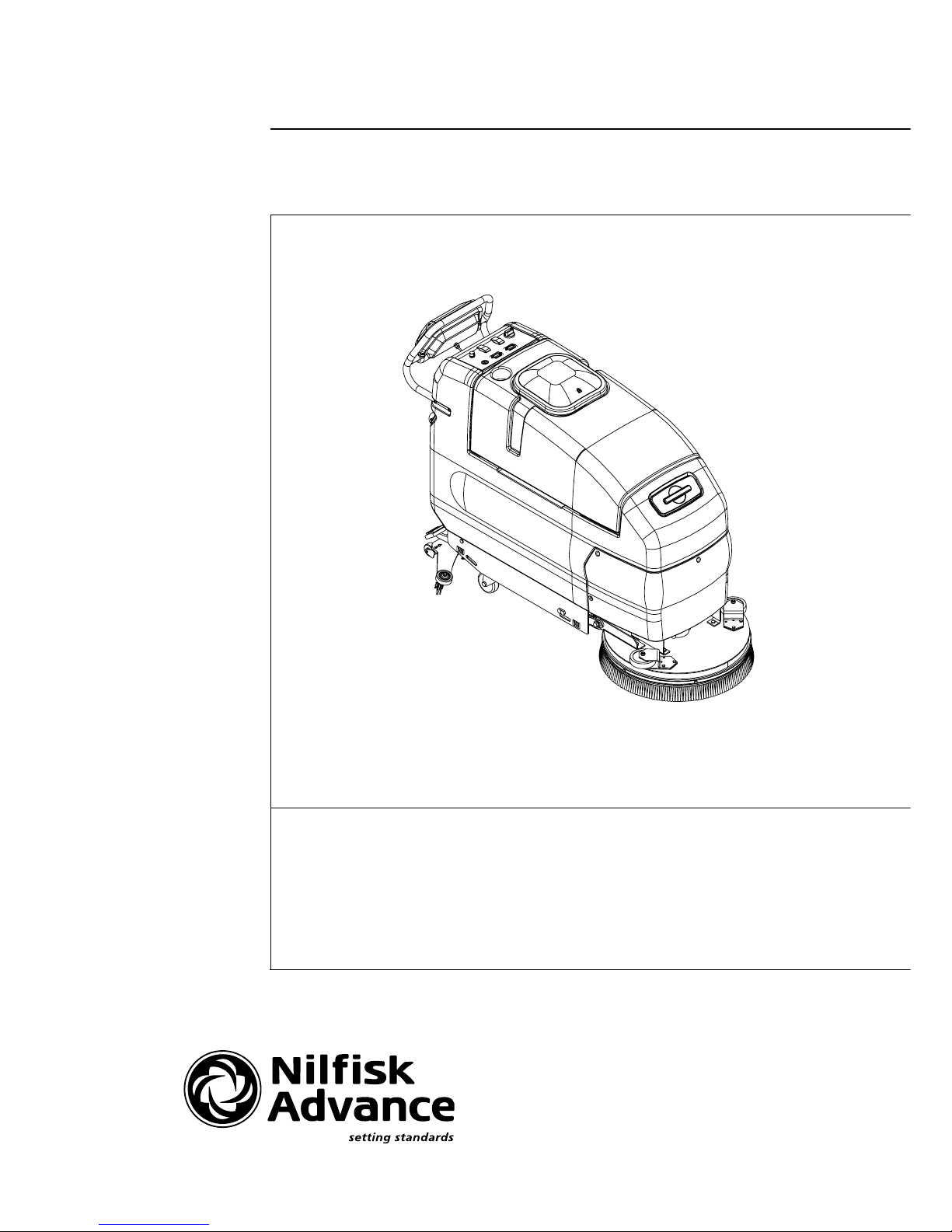
ConvertaMAX™ 20/26
BA 550/650
SERVICE MANUAL
Advance MODELS 56397010, 56397011
56397580, 56397581
Nilfisk MODELS 56397012, 56397013
56397582, 56397583
Page 2

FORM NO. 56043056 / ConvertaMAX™ 20/26 / BA 550/650 - 1
GENERAL INFORMATION ..................................................................................................................................................2
SAFETY INSTRUCTIONS....................................................................................................................................................3
SPECIFICATIONS & MAINTENANCE ............................................................................................................................. 4-6
PM CHECKLIST .................................................................................................................................................................7
KNOW YOUR MACHINE ............................................................................................................................................... 9-13
SOLUTION SYSTEM ................................................................................................................................................... 14-19
FUNCTIONAL OVERVIEW ..............................................................................................................................................14
SOLUTION SYSTEM TROUBLESHOOTING ............................................................................................................ 15-17
SOLUTION SOLENOID VALVE AND STRAINER REMOVAL.........................................................................................18
SOLUTION SOLENOID VALVE DISASSEMBLY AND CLEANING.................................................................................19
SOLUTION FLOW CONTROL VALVE REMOVAL ..........................................................................................................19
SCRUB BRUSH SYSTEM............................................................................................................................................ 20-27
FUNCTIONAL OVERVIEW ..............................................................................................................................................20
TROUBLESHOOTING GUIDE ................................................................................................................................... 21-24
SCRUB BRUSH DECK REMOVAL 20/550 ......................................................................................................................25
SCRUB BRUSH MOTOR/GEARBOX REMOVAL 20/550................................................................................................25
SCRUB BRUSH DECK REMOVAL 26/650 ................................................................................................................ 26-27
SCRUB BRUSH MOTOR/GEARBOX REMOVAL 26/650................................................................................................26
SCRUB BRUSH HEAD SWITCH ADJUSTMENT (machines built before March 2001) ..................................................28
SCRUB BRUSH HEAD SWITCH ADJUSTMENT (machines built after February 2001) .................................................29
RECOVERY SYSTEM.................................................................................................................................................. 30-35
FUNCTIONAL OVERVIEW ..............................................................................................................................................30
VACUUM/RECOVERY SYSTEM MAINTENANCE CHECKLIST.....................................................................................31
TROUBLESHOOTING GUIDE ................................................................................................................................... 31-33
MAINTENANCE OF FLOAT CAGE AND FLOAT DUCT .................................................................................................34
VACUUM MOTOR REMOVAL .........................................................................................................................................35
RECOVERY TANK REMOVAL ........................................................................................................................................35
VACUUM SWITCH REPLACEMENT AND ADJUSTMENT .............................................................................................35
SQUEEGEE SYSTEM.................................................................................................................................................. 36-37
SQUEEGEE TOOL BLADE REPLACEMENT ..................................................................................................................36
SQUEEGEE TOOL ANGLE ADJUSTMENT ....................................................................................................................36
WHEEL DRIVE SYSTEM ............................................................................................................................................. 38-45
FUNCTIONAL OVERVIEW ..............................................................................................................................................38
TROUBLESHOOTING GUIDE ................................................................................................................................... 39-41
CHAIN MAINTENANCE ...................................................................................................................................................42
CHAIN REMOVAL AND ADJUSTMENT ..........................................................................................................................42
WHEEL DRIVE MOTOR REMOVAL ................................................................................................................................42
DRIVE WHEEL REMOVAL ..............................................................................................................................................42
POTENTIOMETER (5K) TESTING AND REMOVAL (for machines built before December 1, 2000)..............................44
POTENTIOMETER INSTALLATION AND ADJUSTMENT (machines before December 1, 2000)..................................45
POTENTIOMETER (5K) TESTING AND REMOVAL (for machines built after December 1, 2000).................................46
POTENTIOMETER INSTALLATION AND ADJUSTMENT (machines after December 1, 2000)............................... 46-47
POTENTIOMETER (25K) TESTING ................................................................................................................................47
ELECTRICAL SYSTEM................................................................................................................................................ 48-53
BATTERIES / CHARGERS SPECIFICATIONS ...............................................................................................................48
INSTALL THE BATTERIES ..............................................................................................................................................48
DESCRIPTION OF THE BATTERY LOW VOLTAGE CUTOUT FEATURE .................................................................... 49
CHARGING BATTERIES .................................................................................................................................................50
BATTERY MAINTENANCE AND BATTERY TESTING ...................................................................................................50
ELECTRICAL COMPONENT LOCATION........................................................................................................................51
WIRING SCHEMATIC ......................................................................................................................................................52
WIRING DIAGRAM .......................................................................................................................................................... 53
Note: All references to right, left, front, or rear in this manual are as seen from the operator’s stand-point.
TABLE OF CONTENTS
revised 7/02
Page 3

2 - FORM NO. 56043056 / ConvertaMAX™ 20/26 / BA 550/650
INTRODUCTION
This manual will help you get the most from your ConvertaMAX™ 20/26 / BA 550/650. Read it thoroughly before servicing the machine.
Note: Bold numbers in parentheses indicate an item illustrated on pages 9-10.
This product is intended for commercial use only.
PARTS AND SERVICE
Repairs, when required, should be performed by your Authorized Nilfisk-Advance Service Center, who employs factory trained service personnel,
and maintains an inventory of Nilfisk-Advance original replacement parts and accessories.
Call the NILFISK-ADVANCE DEALER named below for repair parts or service. Please specify the Model and Serial Number when discussing
your machine.
(Dealer, affix service sticker here.)
NAME PLATE
The Model Number and Serial Number of your machine are shown on the Nameplate on the machine. This information is needed when ordering
repair parts for the machine. Use the space below to note the Model Number and Serial Number of your machine for future reference.
MODEL NUMBER
SERIAL NUMBER
TRANSPORTING THE MACHINE
CAUTION!
Before transporting the machine on an open truck or trailer, make sure that . . .
• The machine is tied down securely - see tie-down locations (26).
• All access doors and covers are secured (tape and strap as needed).
TOWING
CAUTION!
If the machine must be towed or pushed, make sure the Key Switch (Main Power) (18) is in the OFF position, disconnect wheel drive
motor wiring harness and do not move the machine faster than a normal walking pace (2-3 mph, 3-5kph) and for short distances only.
OTHER MANUALS AVAILABLE FOR YOUR MACHINE
The following manuals are available from the Nilfisk-Advance Literature Service Department (order according to model name, model number and machine’s serial
number):
• A Parts List and Operation Manual are available for each machine.
• The three Operation Manuals available for the BA 550/650 are multi-language: (Danish, Norwegian, Swedish, Finnish), (English, German, French,
Netherlands) or (Spanish, Portuguese, Italian, Greek)
GENERAL INFORMATION
revised 7/02
Page 4

FORM NO. 56043056 / ConvertaMAX™ 20/26 / BA 550/650 - 3
SYMBOLS
Nilfisk-Advance uses the symbols below to signal potentially dangerous conditions. Always read this information carefully and take
the necessary steps to protect personnel and property.
DANGER!
Is used to warn of immediate hazards that will cause severe personal injury or death.
WARNING!
Is used to call attention to a situation that could cause severe personal injury.
CAUTION!
Is used to call attention to a situation that could cause minor personal injury or damage to the machine or other property.
GENERAL SAFETY INSTRUCTIONS
Specific Cautions and Warnings are included to warn you of potential exposure to machine damage or bodily harm.
WARNING!
• This machine should only be used by properly trained and authorized persons.
• Keep sparks, flame and smoking materials away from batteries. Explosive gases are vented during normal operation.
• Charging the batteries produces highly explosive hydrogen gas. Charge batteries only in well-ventilated areas, away from open
flame. Do not smoke while charging the batteries.
• Remove all jewelry when working near electrical components.
• Turn the key switch off (O) and disconnect the batteries before servicing electrical components.
• Never work under a machine without safety blocks or stands to support the machine.
• Do not dispense flammable cleaning agents, operate the machine on or near these agents, or operate in areas where flammable
liquids exist.
• Do not clean this machine with a pressure washer.
• Do not operate this machine on ramps or inclines of more than a 2 percent gradient.
CAUTION!
• This machine is not approved for use on public paths or roads.
• This machine is not suitable for picking up hazardous dust.
• Use care when using scarifier discs and grinding stones. Advance will not be held responsible for any damage to floor surfaces
caused by scarifiers or grinding stones.
• When operating this machine, ensure that third parties, particularly children, are not endangered.
• Before performing any service function, carefully read all instructions pertaining to that function.
• Do not leave the machine unattended without first turning the key switch off (O), removing the key and securing the machine.
• Turn the key switch off (O) before changing the brush(es), and before opening any access panels.
• Take precautions to prevent hair, jewelry, or loose clothing from becoming caught in moving parts.
• Use caution when moving this machine in below freezing temperature conditions. Any water in the solution or recovery tanks
or in the hose lines could freeze.
SAVE THESE INSTRUCTIONS
CAUTIONS AND WARNINGS
Page 5

4 - FORM NO. 56043056 / ConvertaMAX™ 20/26 / BA 550/650
General Specifications English (Metric)
Machine Length
20” Models 64 in. (162cm)
26” Models 59 in. (149cm)
Machine Width with Squeegee
20” Models 30.5 in. (77cm)
26” Models 36.25 in. (92cm)
Machine Height 42.5 in. 108cm)
Machine Net Weight*
20” Models 362 lbs. (164kg)
26” Models 384 lbs. (174kg)
Machine Gross Weight**
20” Models 626 lbs. (284kg)
26” Models 648 lbs. (297kg)
Cleaning Width (scrubbing path)
20” Models 20 inches (51cm)
26” Models 26 inches (66cm)
Coverage Rate Per Hour (theory)
20” Models 28,000 sq. ft. (2600m2)
26” Models 34,500 sq. ft. (3205m2)
Coverage Rate Per Hour (average)
20” Models 9,000 sq. ft. (836 m2)
26” Models 11,300 sq. ft. (1050 m2)
Brush Diameter 20” Models (qty of 1) 20 inches (50.8cm)
Brush Diameter 26” Models (qty of 2) 13 inches (36cm)
Brush Speed (20”) 200 RPM
Brush Speed (2 x 13”) 220 RPM
Brush Pressure
20” Models Low - 45 lbs. (20kg) High – 80 lbs. (36kg)
26” Models Low – 70 lbs. (32kg) High – 110 lbs. (50kg)
Solution Tank Capacity 20 gal. (76l.)
Recovery Tank Capacity 20 gal. (76l.)
Vacuum Water Lift 63 inches (sealed)
14 inches (open hole adapter 1”)
Ramp Climbing Ability (gradeability) 2% grade
Sound power level as per ISO 3744 (at operator) 70 dB(A)/20µPa
Transport Speed (Maximum) 3.3 mph (5.3KPH)
Scrubbing Speed (Maximum) 3 mph (4.8KPH)
Power Source 24VDC Battery Pack (4) 6V/238 AH batteries
Battery Weight (each) 66lbs. (29.9kg)
Battery Compartment Size
Height 13.25 inches (33.6cm)
Width 15.5 inches (39.3cm)
Length 20.5 inches (52cm)
Battery Chargers Automatic 24V – 20A DC / 115V 60Hz AC
Wheel Drive Motor .5 hp, 373 watt
Brush Drive Motor (20” Models) (1) 1 hp, 746 watt
Brush Drive Motor (26” Models) (2) .75 hp, 560 watt
Vacuum Motor .75 hp, 570 watt
Machine Current (Average) 20” Models: 40 Amps 26” Models: 50 Amps
*Net Weight: Standard machine without options, empty solution and recovery tanks, without removable scrub brushes and no battery installed.
**Gross Weight: Standard machine without options, empty solution tank and empty recovery tank, with removable scrub brushes and 238 AH batteries.
SPECIFICATIONS
revised 9/00
Page 6
FORM NO. 56043056 / ConvertaMAX™ 20/26 / BA 550/650 - 5
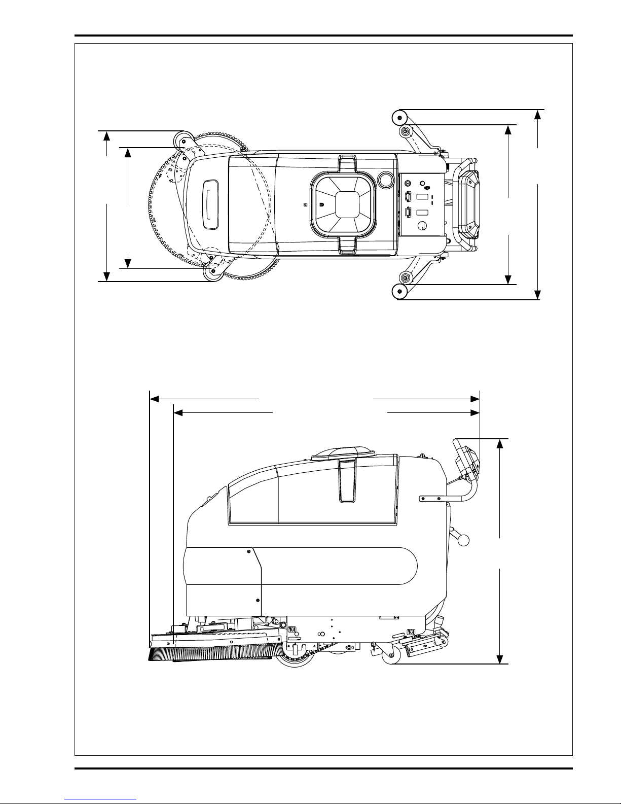
SPECIFICATIONS
TOP VIEW
SIDE VIEW
30.5 in.
(77cm)
20" Models
64 in. (162cm) 20" Models
59 in. (149cm) 26" Models
42.5 in.
(108cm)
26.5 in.
(67.3cm)
20"
Models
28.5 in.
(72.4cm)
26"
Models
36.25 in.
(92cm)
26" Models
Page 7

6 - FORM NO. 56043056 / ConvertaMAX™ 20/26 / BA 550/650
MAINTENANCE
MAINTENANCE SCHEDULE
Maintenance intervals given are for average operating conditions. Machines used in severe operational environments may require
service more often.
MAINTENANCE ITEM Daily Weekly Monthly Yearly
Charge Batteries •
Drain/Clean and Check Tanks & Hoses •
Check/Clean/Rotate the Brushes/Pads •
Check/Clean/Adjust the Squeegee ••
Check/Clean Vacuum Shut-Off Float •
Check Each Battery Cell(s) Water Level •
Inspect and Clean Solution Filter •
Lubrication – Grease Fittings •
*Check Motor Carbon Brushes •
Note: See the individual machine system sections for maintenance information.
* Have Nilfisk-Advance:
IMPORTANT!
Motor damage resulting from failure to service the carbon brushes is not covered under warranty. See the Limited Warranty
Statement.
Check vacuum motor carbon brushes (Qty 2) once a year or after 300 operating hours.
Note if the vacuum or brush motor carbon brushes are 9.5mm (3/8 inches) or shorter, replace them.
Check brush motor carbon brushes (Qty 4) once a year or after 500 operating hours.
Check wheel drive motor carbon brushes every 500 operating hours. The original length of each brush is 20mm (25/32 inches).
Replace when shorter than 9.5 mm (3/8 inches) to obtain the same motor efficiency as a new brush.
WARNING!
Turn the key switch off and disconnect the battery before servicing the machine.
BATTERIES AND CHARGERS
Attention: See the electrical system manual section for battery installation and charger system requirements.
LUBRICATING THE MACHINE
Once a month, pump a small amount of grease into each grease fitting on the machine until grease seeps out around the bearings.
Grease fitting locations are:
• Rear Caster Wheel Axle & Swivel (2) per Assembly
Once a month, apply light machine oil to lubricate the:
•Drive Chain
• Squeegee Height Adjustment Caster Hardware
•Pivot Points For the Squeegee & Scrub Brush Linkage
Page 8

FORM NO. 56043056 / ConvertaMAX™ 20/26 / BA 550/650 - 7
revised 7/02
Copyright 2001 Nilfisk-Advance. 8/09/01
Advance ConvertaMAX 20/26 Models 56397010, 56397011, 56397580, 56397581
Nilfisk BA 550/650 Models 56397012, 56397013, 56397582, 56397583
PM Checklist
Defect Codes
Customer
A needs adjustment
B binding
Address
C dirty or contaminated
D damaged, bent or torn
City
St Zip L leaks
M missing
Model
Serial Hours W worn out
Ref
OPERATIONAL INSPECTION ITEMS
OK
Defect Codes
(circle)
Does
Not
Work
1Drive Paddle Operation (check for Fwd/Rev Drive & any neutral creep) A B D
2Drive System Performance (Speed Changes Min/Max) noisy sluggish
3 Scrub System (Raise/Lower, Brush Motor On/Off, Brush install & Remove Feature) A B D
4 Scrub Brush (pressure settings Normal & Heavy) A B
5 Squeegee System (Raise/Lower & Squeegee Tool pickup Performance) A B D
6Vacuum Performance (Sealed water lift 63" and 1- inch open hole adapter 14 inches) C L W
7 Solution Control (On/Off Manual /Auto and Flow Volume Min/Max) A B L
8Battery Charger (Auto turn ON & OFF) D
Ref
VISUAL INSPECTION ITEMS
Comments OK
Defect Codes
(circle)
Does
Not
Work
9 Scrub Brushes, check for wear and rotate D M W
10 Scrub Brush Motor(s), check for carbon brush wear 500 Hours B C W
11 Scrub Brush Motor(s), check gearboxes B D L
12 Brush Drive Plate Retainer Clips & flex couplers C D M
13 Scrub Deck Skirts and Side Wheels D M W
14 Solution Solenoid Valve C D L W
15 Solution Flow Control Valve and Linkage A B D W
16 Solution Tank, Delivery Hoses & Filter Clean filter screen C L
17 Vacuum Motor Carbon Brushes (wear limit 3/8”) 300 Hours B C W
18 Vacuum Motor Gaskets and Filters C D L
19 Vacuum Float Ball & Cage Assembly Clean float C D M
20 Recovery Tank Cover Gasket L M W
21 Recovery Tank Drain Hose & Cap C D L
22 Squeegee Pick-Up Hose Back flush C D L
23 Squeegee Tool & Blades (clean & rotate) A D W
24 Squeegee Tool Wheels (lubricate) Two side and two
floor
A D W
25 Battery Condition (load test, clean & water) C W
26 Front Drive Wheel Motor Check Carbon Brushes 500 Hours B C W
27 Front Drive Tire tread wear W
28 Drive wheel Motor Chain (Lubricate and tension) A B C W
29 Rear chassis Caster Wheels (Lubricate) tread wear W
NOTE: For additional service information see service manual form number 56043056 and
operators manual form numbers 56041459, 56041460, 56041461.
WORK COMPLETED BY: ACKNOWLEDGED BY:
Service Technician Signature Date Customer Signature Date
Page 9

8 - FORM NO. 56043056 / ConvertaMAX™ 20/26 / BA 550/650
BLANK PAGE
revised 9/01
Page 10
FORM NO. 56043056 / ConvertaMAX™ 20/26 / BA 550/650 - 9
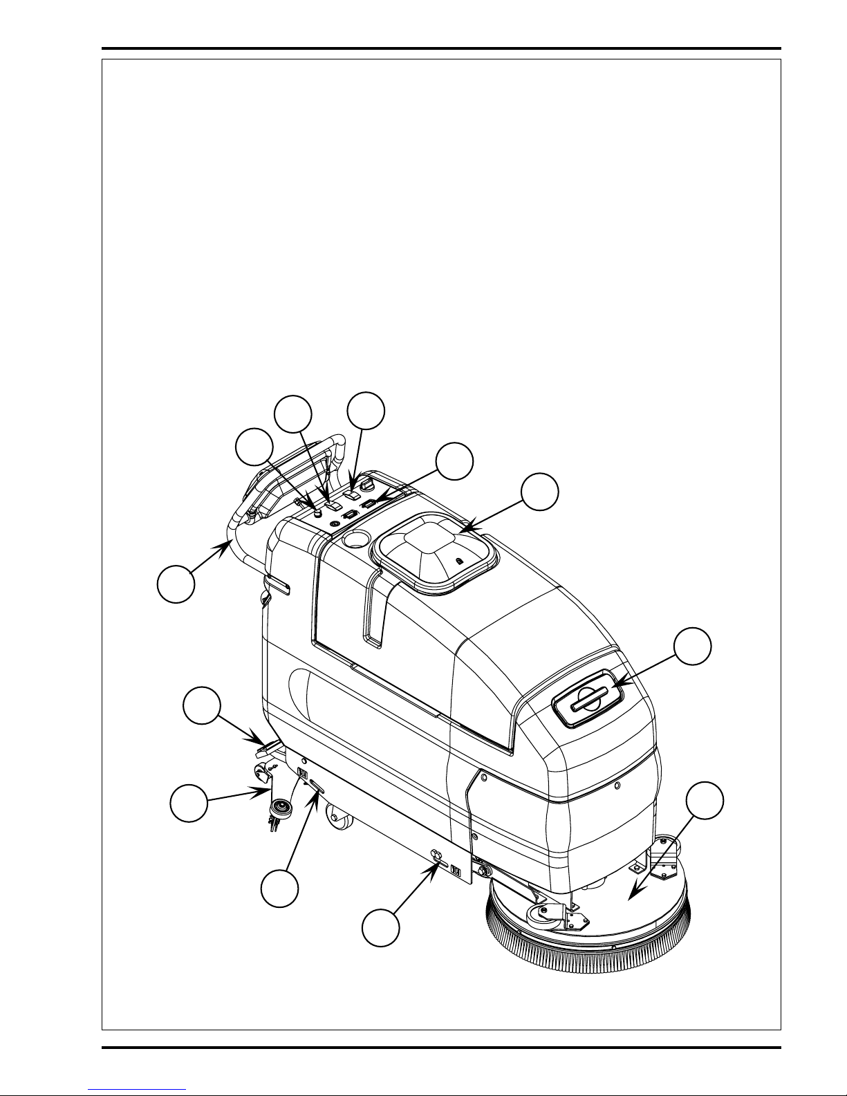
1 Solution Tank Fill Openings (2)
2 Recovery Tank Cover
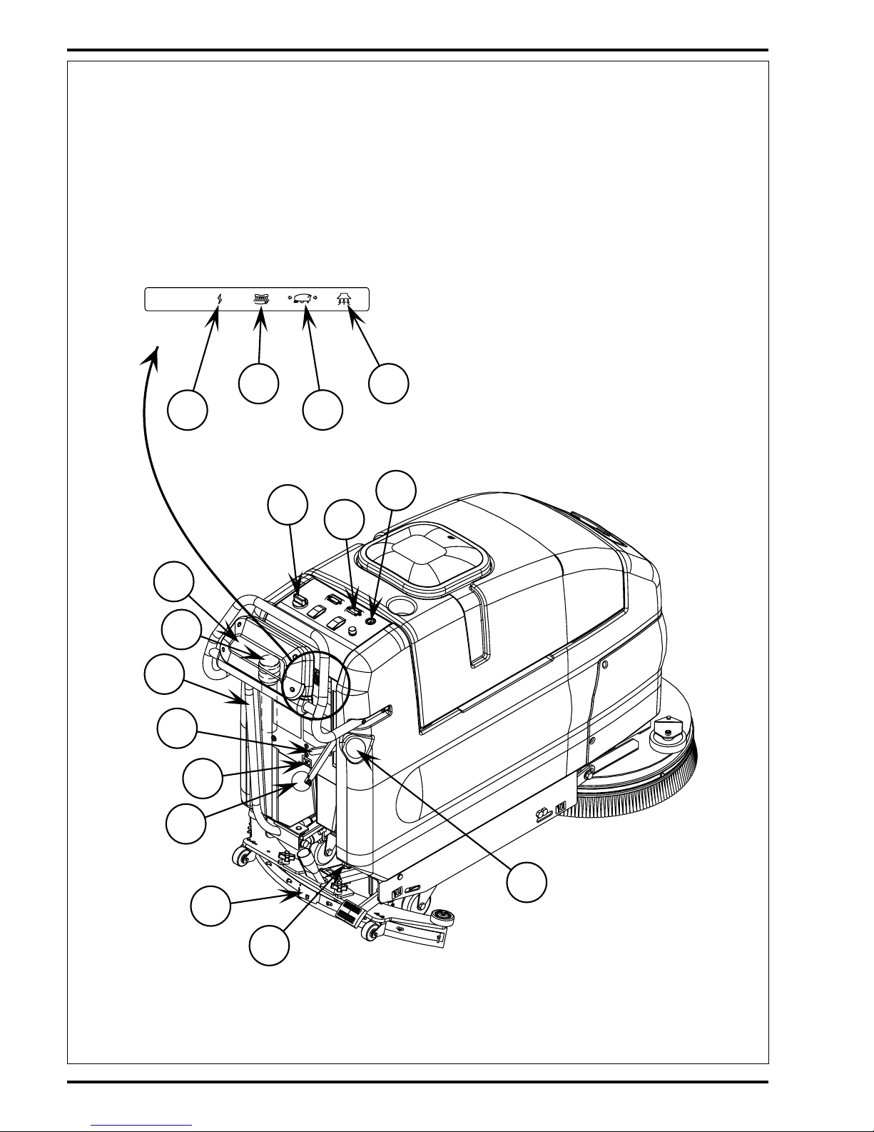
3 Vacuum / Squeegee Lever
4 Brush Raise / Lower Pedal
5 Drive Paddle
6 Solution Drain Hose / Level Indicator
7 Recovery Drain Hose
8 Squeegee Adjustment Knob
9 Squeegee Blade Latch
10 Squeegee
11 Battery Charger Connector
12 Battery Fuel Gauge
13 Hour Meter
14 Solution Switch, ON-Momentarily ON-OFF
15 Brush Remove Switch
16 Solution Flow Control Knob
17 Speed Limit Control Knob
18 Master Key Switch
19 Auxiliary Circuit Breaker
20 Vacuum Motor Circuit Breaker
21 Brush Motor Circuit Breaker
22 Wheel Drive Circuit Breaker
23 Scrub Pressure Lever
24 Brush Deck
25 Operator Control Handle
26 Tie Downs
1
2
10
4
12
14
15
17
24
25
26
26
KNOW YOUR MACHINE
revised 9/01
Page 11
10 - FORM NO. 56043056 / ConvertaMAX™ 20/26 / BA 550/650
3
5
6
8
9
11
13
16
18
19
20
22
21
23
7
1
KNOW YOUR MACHINE
revised 9/01
Page 12

FORM NO. 56043056 / ConvertaMAX™ 20/26 / BA 550/650 - 11
FUNCTIONAL DESCRIPTION OF CONTROL BUTTONS:
Solution Tank Fill (1) – Open to fill the solution tank, use non-foaming chemicals only (capacity 20 gal. / 75 liters)
Recovery Tank Cover (2) – Point of entry for waste water into tank. Also houses float ball which shuts off vacuum port to vac motor
when tank is full.
Squeegee Lever (3) – This lever controls both the squeegee and the vacuum motor. There are three positions: OFF, vacuum ON
and vacuum ON with the squeegee on the floor.
*Off
* Vacuum ON
This position lifts the squeegee slightly while leaving the vacuum turned on. This can be used for backing up during scrubbing,
or supplies vacuum for cleaning remote areas using an attachment.
* Vacuum ON with the squeegee on the floor
This position is for picking up solution while scrubbing.
Brush Raise / Lower Pedal (4) – Located at the right rear corner near the floor, this pedal is used to raise or lower the brush head.
Drive Paddle (5) – Located on top at the rear of the machine, the operator can make the machine go forward by pushing forward
on it, or reverse by pulling backward on it. The speed is variable depending on how far forward or backward the paddle is moved.
When the brush head is in the “DOWN” position, the brushes and solution will operate when the drive is engaged in either direction,
but will stop after the machine is stationary for 1 second.
Solution Drain Hose / Level Indicator (6) – Used to empty the solution tank and show current level of solution in tank, graduations
are marked on the side of the solution tank next to the hose.
Recovery Drain Hose (7) – Used to empty the recovery tank.
Squeegee Adjustment Knob (8) – Used to adjust the tilt of the squeegee. Turn knob clockwise to tilt the squeegee backwards and
counter-clockwise to tilt it forward.
Squeegee Blade Latch (9) – Holds rear squeegee blade and straps in place, release to replace rear blade.
Squeegee (10) – Picks up solution after scrubbing.
Battery Charger Connector (11) – Plug battery charger into this port to charge batteries.
Battery Fuel Gauge (12) – Shows current state of charge of batteries.
Hour Meter (13) – Displays number of hours machine has been used.
Solution Switch (14) – This switch is used to select the mode of operation for the solution system. There are 3 modes of operation
for this system. The modes are OFF, ON, MOMENTARY ON. Following is a description of each mode and how they are selected.
OFF: In this mode the solution flow is turned off.
ON: In this mode the solution flow will be turned on whenever the Drive Paddle (5) is in forward or reverse mode and the brush head
is down. The solution flow will be turned off otherwise.
MOMENTARY ON: – Solution can be dispensed by pressing and holding the solution button. Solution will be dispensed for as long
as the button is held. This is for pre-wetting the floor prior to scrubbing.
KNOW YOUR MACHINE
revised 9/01
Page 13

12 - FORM NO. 56043056 / ConvertaMAX™ 20/26 / BA 550/650
Brush Remove Switch (15) – To remove the brush(es) from the machine, have the machine stationary and the Brush Deck (24) in
the “RAISED” position. Press the switch to the “REMOVE” position and release. The switch will snap to the OFF position, and the
brush(es) will drop to the floor.
Solution Flow Control Knob (16) – Turn this dial to the right to increase solution flow to the floor. Turn to the left, to decrease the
amount of solution flow to the floor. When the Drive Paddle (5) is released from either forward or reverse travel, the solution flow will
stop automatically, and resume when the drive is engaged.
Speed Limit Control Knob (17) – The Speed Limit Control Knob is used to adjust the maximum speed in both forward and reverse.
Master Key Switch (18) – The master power switch.
Auxiliary Circuit Breaker (19) – Provides overload protection. If it trips, it will pop out. To reset, wait one minute and press the button
back in. If any breaker trips repeatedly, have the machine serviced.
Vacuum Motor Circuit Breaker (20) – Provides overload protection to machine’s vacuum motor. If it trips, it will pop out. To reset,
wait one minute and press the button back in. If any breaker trips repeatedly, have the machine serviced.
Brush Motor Circuit Breaker (21) – Provides overload protection to machine’s brush motor(s). If it trips, it will pop out. To reset,
wait one minute and press the button back in. If any breaker trips repeatedly, have the machine serviced.
Wheel Drive Circuit Breaker (22) – Provides overload protection to machine’s wheel drive motor. If it trips, it will pop out. To reset,
wait one minute and press the button back in. If any breaker trips repeatedly, have the machine serviced.
Scrub Pressure Lever (23) – Two position lever provides two different scrubbing pressures.
TOP POSITION: – In this position the full weight of the scrub deck rests on the floor.
BOTTOM POSITION: – In this position the scrub pressure is approximately 30 pounds less.
Brush Deck (24) – Contains brush drive motor(s) and brush(es).
Operator Control Handle (25) – Operator holds onto this to control the machine.
KNOW YOUR MACHINE
revised 9/01
Page 14

FORM NO. 56043056 / ConvertaMAX™ 20/26 / BA 550/650 - 13
CONTROL MODULE DESCRIPTION
The ConvertaMAX™ 20/26 / BA 550/650 scrubbers have an electronic module that controls the activation of the scrub brush motors
for scrubbing and removal of the brushes/pads and the low voltage cutout function.
For normal scrubbing the brush motor(s) will activate only if the brushes are down and the Drive Paddle (5) (throttle) is in the forward
or reverse position.
For removal of the brushes/pads the scrub deck must be in the up position. To remove the brushes/pads simply depress the Brush
Remove Switch (15). The module will momentarily run the brush motor and then stop it quickly.
The low voltage cutout is adjustable for two different thresholds. The normal setting cuts out at 1.75 volts per cell and the alternate
setting cuts out at 1.83 volts per cell. The cutout level is selected by momentarily depressing the pushbutton switch located on the
module circuit board.
*Important Note: See the Low Voltage Cutout Level Selection manual section in the Electrical System and follow the instructions
for setting the low voltage cutout threshold.
DESCRIPTION OF THE BATTERY FUEL GAUGE
The Battery Fuel Gauge (12) uses a 10 bar LED display that indicates the state of the batteries charge, successively, bar by bar, from
full to empty. At 70% depth of discharge a single flashing light signals an energy reserve alert. At 80% of discharge, a double flashing
light signals an empty alarm. The battery gauge will retain the last state-of-charge condition even when the machine has been turned
off. The battery fuel gauge state-of-charge display indication is automatically reset to full charge when the battery pack is recharged.
KNOW YOUR MACHINE
revised 9/01
Page 15
14 - FORM NO. 56043056 ConvertaMAX™ 20/26 / BA 550/650
SOLUTION SYSTEM
FRONT
Solution
Solenoid Valve
(L1)
Solution Filter
Main Solution
Valve
To Brush(es)
Solution Flow
Control Knob
From Solution
Tank
FRONT
A
B
C
Drain Hose
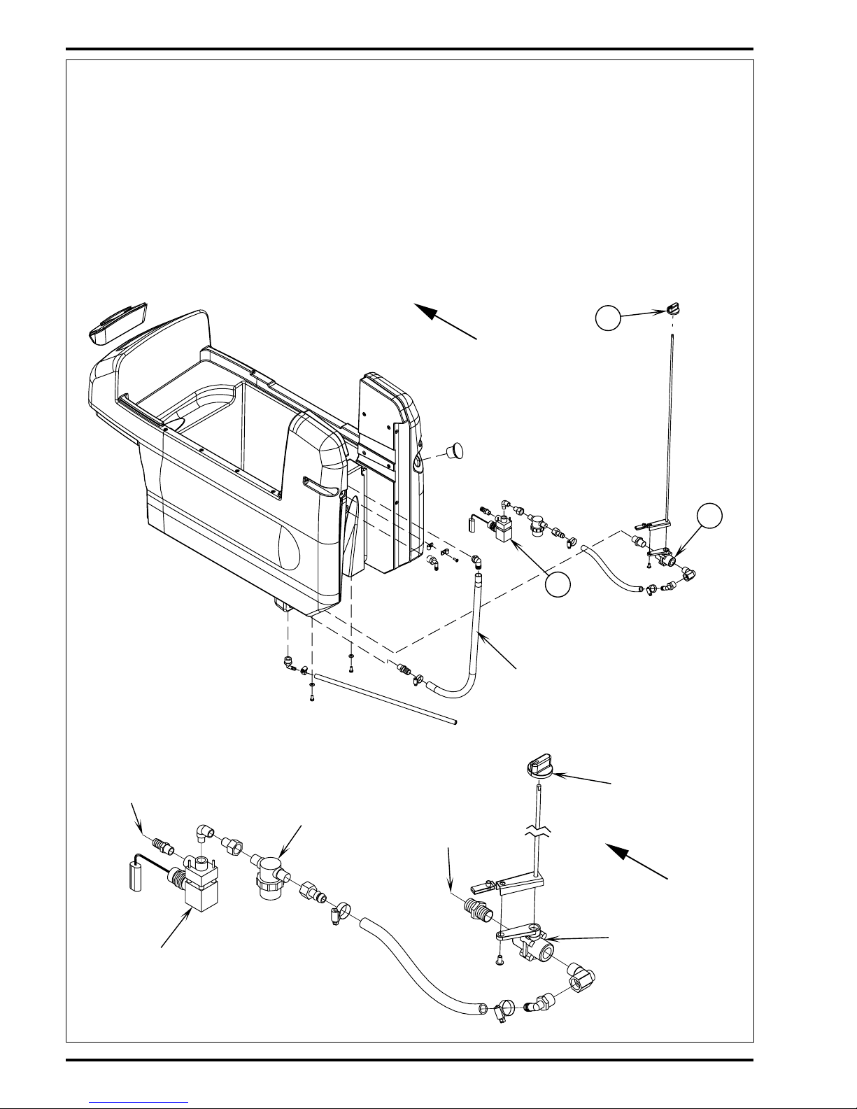
FUNCTIONAL OVERVIEW
The 20-gallon (76 l.) capacity solution tank uses two fill openings one located in the front and another in the rear, which offers ease of filling. Plumbed
onto the tank outlet is a serviceable solution filter, to keep debris from entering the solenoid valve. Also fitted to the tank is flexible hose used to
indicate the solution level and to drain the tank for system maintenance.
See Figure 1. The solution system uses (2) valves to regulate the amount of solution dispensed onto the floor. The Knob (A) located on the control
panel operates the Main Solution Valve (B) that controls the needed flow volume demanded by the scrub brushes. The electrical solenoid valve
(L1) (C) and control panel mounted solution switch (S2) start and stop the solution flow (See Electrical Diagram).
During normal machine operation the (S2) solution switch when turned ON works in conjunction with the wheel drive controller components and
brush motor solenoid output to energize the (L1) solenoid valve. The solution will flow to the scrub brushes when the main flow control valve is
open, the scrub deck is lowered and the handle drive paddle (box) is pushed or pulled into Fwd or Rev. Note: When the solution On/Off switch
(S2) is turned Off, no flow can occur regardless of the main valve being On and the drive control paddle being activated.
FIGURE 1
FIGURE 2
revised 9/01
Page 16
FORM NO. 56043056 ConvertaMAX™ 20/26 / BA 550/650 - 15
SOLUTION SYSTEM
-
+
1
2
3
4
5
6
5124
3
10
61
11
987
2
S6
D2
L1
R1
R2
S2
K1
F2
A2
Voltage Cutout
Button
LIQ
.
GEL
.
A1
F3
P1
B-B+
P2
+24V -24V
S1
YEL/BLK
YEL/WHT
VIO/BLK
BLK/YEL
VIO
BLK
ORN/BLK
WHT/RED
#12
VIO/BLK
#10
BLK
VIO
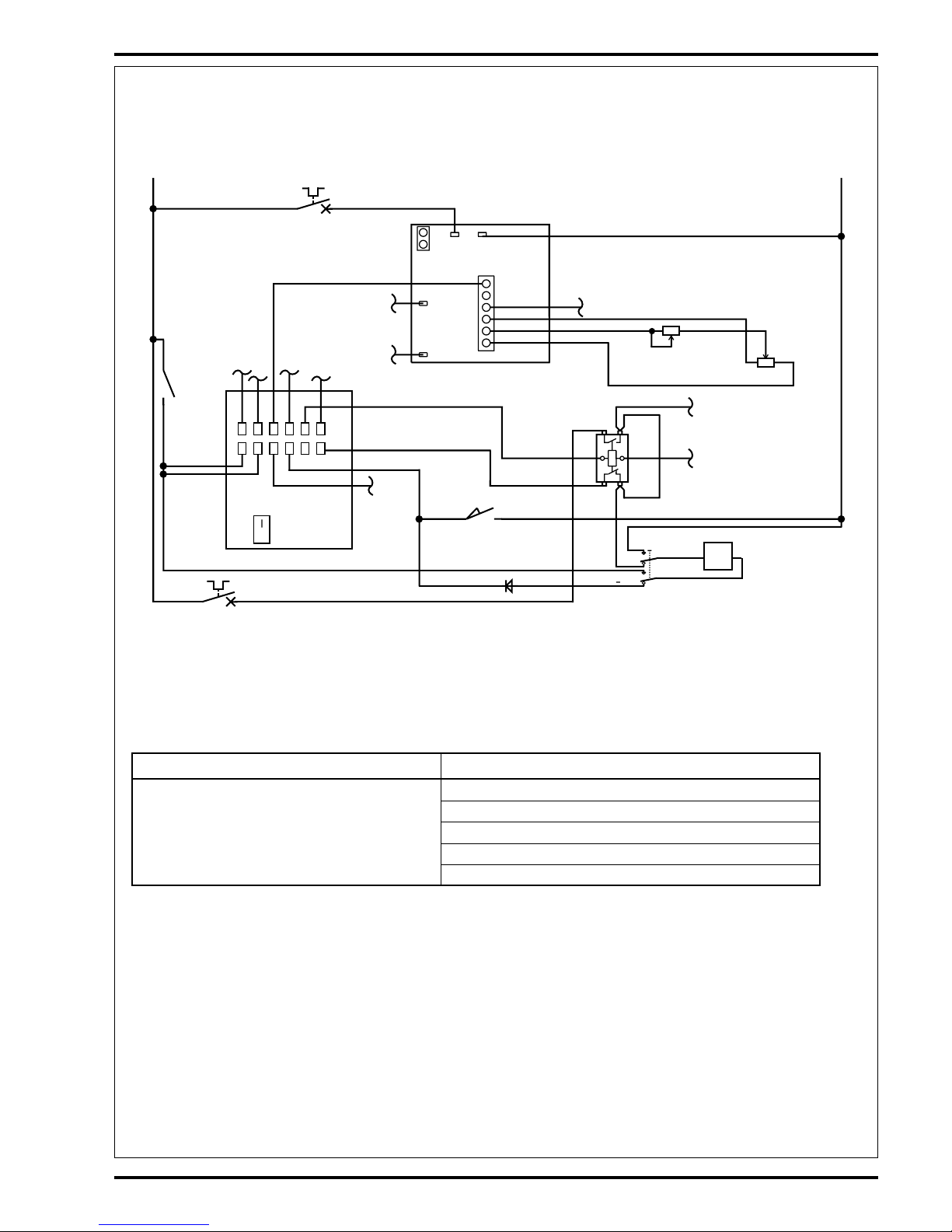
Electrical Diagram (Solution Switch Closed in the Full ON Position)
*For complete description of all callouts see Electrical System Wiring Diagram.
TROUBLESHOOTING GUIDE
Problem Possible Cause
Inadequate or no solution flow No solution in the tank
Main solution flow control valve knob is in the off position
Clogged solution filter, valves and hoses
Defective solution solenoid valve (L1)*
Defective control panel solution switch (S2)**
*See Solenoid Troubleshooting flow chart Symptom One for electrical system diagnostics.
**See Troubleshooting flow chart Symptom Two.
FIGURE 3
revised 9/01
Page 17
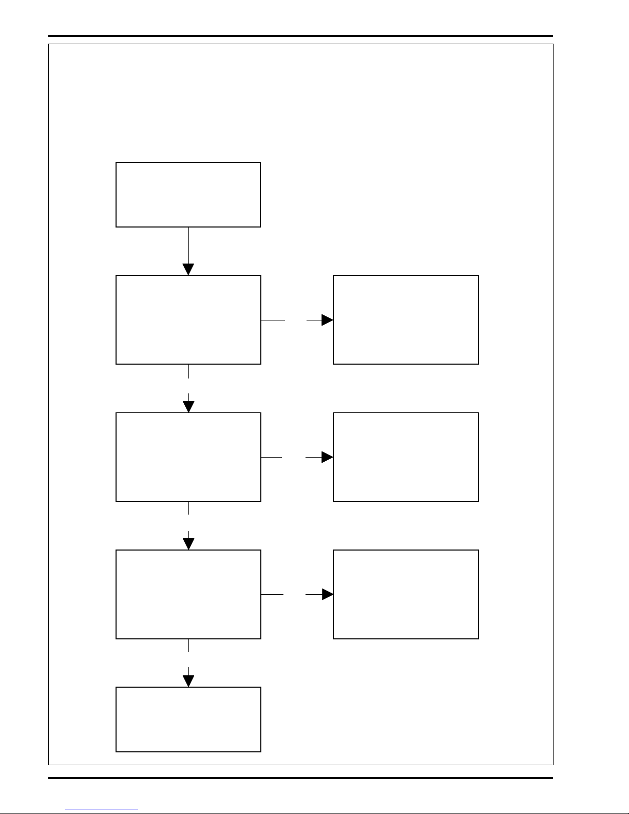
16 - FORM NO. 56043056 ConvertaMAX™ 20/26 / BA 550/650
SOLUTION SYSTEM
No
Yes
Yes
No
Yes
No No
Yes
Yes
No No
Yes
No
Yes
Solenoid will
not open, no
solution flow
(See Figure 3).
Verify scrub
brush(es) are
turning
See Brush System
Troubleshooting
Symptom 2 (part
A&B).
Separate the wiring
harness connector
that feeds the L1
solenoid (2 wires
Yel/Wht & Yel/Blk).
Test for 24V
Test the resis-
tance of the L1
solenoid coil. If it
reads infinity coil
is open or if it
reads 40 ohms or
less it is shorted
(a good coil
should read 63
ohms ±10%).
Check for 24V
(Pos.) from the
Yel/Wht L1 harness
feed wire to a
(Neg.) battery
standoff
Replace the L1
solenoid coil if
testing shows it
shorted or open.
Check for 24V
(Pos.) at the
Blk/Yel input wire
on the S2 solution
switch
Test continuity of
the Blk/Yel & #12
wires from the K1
solenoid to the S2
solution switch.
Repair or replace
Replace the S2
solution switch
Check for 24V
(Neg.) from the
Yel/Blk L1 harness
feed wire to a (Pos.)
battery standoff
Check for 24V
(Neg.) at the
Vio/Blk input wire
on the S2 solution
switch
Replace the S2
solution switch
Check diode D2
for continuity in
one direction only
If diode checks
open replace the
D2 diode
Replace the L1
solenoid valve
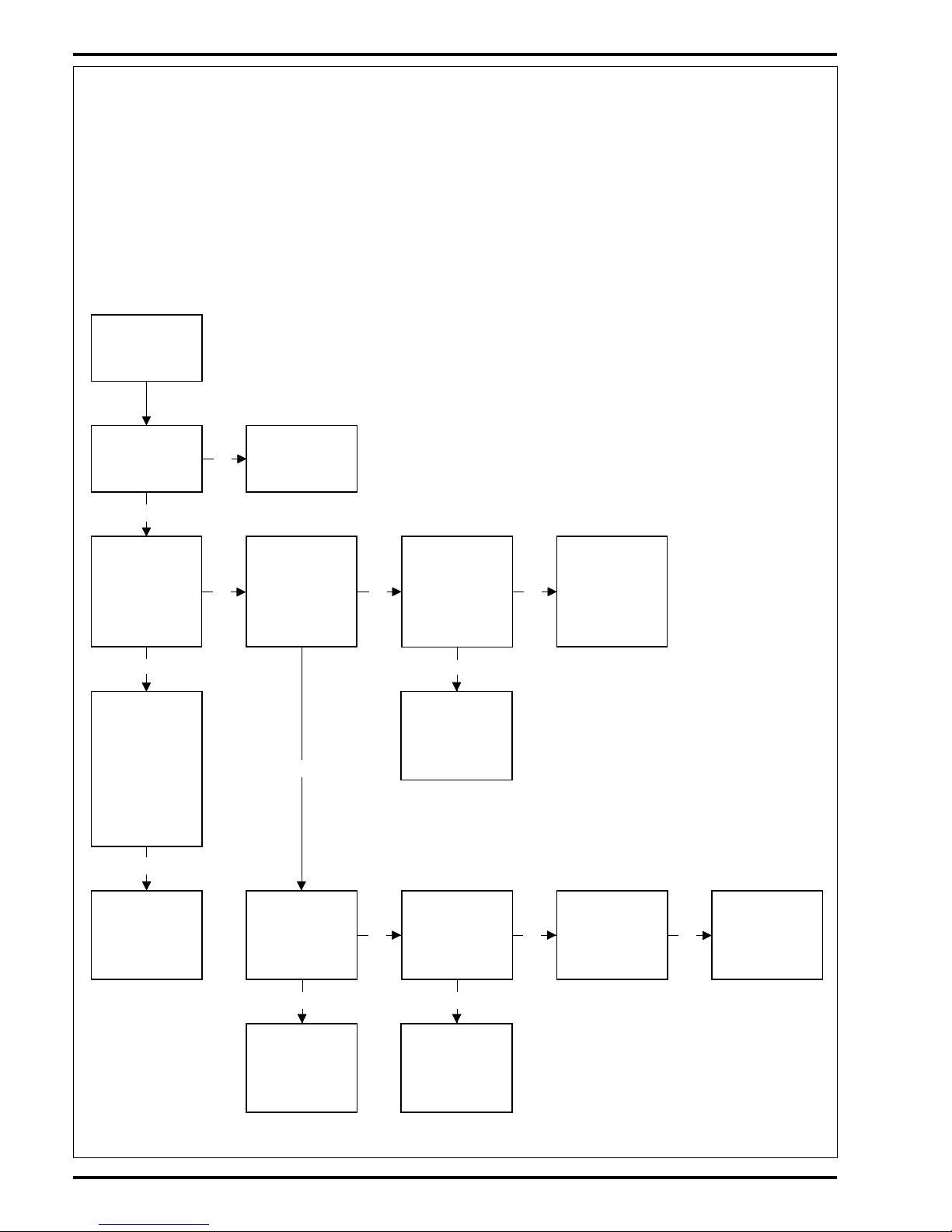
TROUBLESHOOTING GUIDE ELECTRICAL
Possible Symptoms
1 Solution solenoid valve will not open when the solution switch is in the full on position.
2 Solution solenoid valve will not open when the solution switch is in the momentary on position.
SYMPTOM ONE
Note: Do all testing with the key switch on, brush switch closed (scrub deck lowered) and the drive paddle activated
(pushed Fwd or pulled into Rev).
revised 9/01
Page 18

FORM NO. 56043056 ConvertaMAX™ 20/26 / BA 550/650 - 17
SOLUTION SYSTEM
SYMPTOM TWO
Note: Test with the key switch on and the solution switch held in the momentary on position.
TROUBLESHOOTING GUIDE ELECTRICAL (CONTINUED)
No
Yes
No
No
Yes
L1 solenoid will not
open when the S2
switch is in the
momentary on
position, no solution
flow (See Figure 3).
Check for the 24V
input at the S2 solu-
tion switch, Vio &
Blk wires
Check for 24V (Pos.)
from the Vio S2
switch wire to a
(Neg.) battery
standoff.
Replace the S2
solution switch
Check for 24V (Neg.)
from the Blk S2
switch wire to a
(Pos.) battery
standoff.
Repair or replace
the Blk wire
Repair or replace
the Vio wire
revised 9/01
Page 19
18 - FORM NO. 56043056 ConvertaMAX™ 20/26 / BA 550/650
SOLUTION SYSTEM
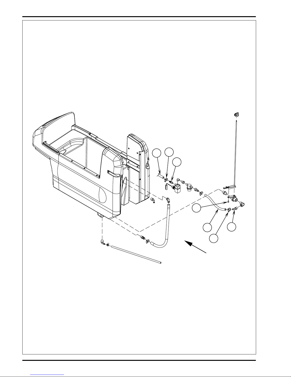
SOLUTION SOLENOID VALVE AND STRAINER REMOVAL
1 Drain the solution tank using the tank drain hose.
2 See Figure 4. Loosen (D) Hose Clamp and pry the Hose (E) from the Elbow Fitting (F) as shown.
3 Loosen the (G) Hose Clamp and remove the (H) solution feed hose from the (I) solenoid valve barb.
4 Loosen the solenoid valve mount anchor connector, and then disconnect the valves’ wiring harness connector.
5 Pull out from underneath the machine the combined valve and strainer assembly. Make service repairs as required and re-install in reverse order.
FRONT
H
I
F
E
M
D
G
FIGURE 4
revised 9/01
Page 20

FORM NO. 56043056 ConvertaMAX™ 20/26 / BA 550/650 - 19
SOLUTION SYSTEM
SOLENOID VALVE DISASSEMBLY AND CLEANING
1 Remove the solenoid valve. See the Solution Solenoid Valve And Strainer Removal section for instructions.
2 See Figure 5. Remove the (2) (J) Screws and nuts and disassemble the valve (be careful not to lose any internal parts).
3 Thoroughly wash dirt from block (K) and diaphragm (L).
4 After reassembling, test the solenoid valve for proper operation.
Note: Solenoid valve replacement seal kit (Viton) part number 56324247.
SOLUTION FLOW CONTROL VALVE REMOVAL
1 Drain the solution tank and also remove the squeegee tool from the machine (this allows the needed room to work on the valve).
2 See Figure 4. Loosen the Hose Clamp (D) and pull the Hose (E) off the valve elbow fitting (F).
3 Remove the Screw (M) that holds together both the water valve shaft arm and the solution valve arm.
4 Separate the control arms and work the shaft up and off the valve to allow the clearance for removal.
5 Turn the valve out of the solution tank connection and remove it from the machine. Note it is not necessary to remove the tank drain hose, just compress
the hose to allow needed clearance to remove the valve.
revised 9/01
J
FRONT
K
L
J
FIGURE 5
Page 21

20 - FORM NO. 56043056 ConvertaMAX™ 20/26 / BA 550/650
SCRUB BRUSH SYSTEM
+
1
2
3
4
5
6
5
12
4
3
10
61
11
987
2
-
+
S6
D2
L1
R1
R2
S2
K1
F2
A2
Battery Switch
LIQ.
GEL
.
A1
F3
P1
B-B+
P2
+24V -24V
S1
M
M
M3
M4
S3
BLKVIO/BLK
#10#14
BLK
#12
#16
BRN
ORN/BLK
WHT/RED
#8
BRN/WHT
GRA
VIO
GENERAL BRUSH SYSTEM FUNCTIONAL OVERVIEW
The ConvertaMAX™ 20 / BA 550 models use (1) scrub brush (20 inch Dia.) driven by a single 1HP 24VDC-combination motor/gear unit. The
ConvertaMAX™ 26 / BA 650 models use (2) scrub brushes (two 13 inch Dia.) driven by two 3/4HP 24VDC combination motor/gear units. The
scrub deck is raised and lowered manually by a rear mounted foot pedal.
Control Module Scrub System Functions
The ConvertaMAX™ 20/26 / BA 550/650 scrubbers have an electronic timer module (A2) that controls the activation of the scrub brush motors,
special scrub brush removal feature and a low voltage cutout function.
Scrub Brush Removal Function
For removal of the scrub brush(es) automatically the scrub deck must be in the up position and the drive system in neutral. To remove the scrub
brush(es) simply depress the control panel remove switch (S3). The timer module will momentarily run the brush motor and then stop it quickly,
where the brush inertia causes the brush to easily spin it’s self off of the scrub brush motor drive cap.
Low Voltage Cut-Out Function
The purpose of the special low battery voltage cutout function is to help prolong battery life. The brush motor(s) and solution solenoid valve will
turn off automatically and cease to function when the batteries discharge to 1.75 volts per cell or 1.83 volts per cell on alternate setting. Note: See
the battery system section for instructions for selecting (setting) the two different thresholds (wet cell, lead acid or gel, maintenance free). Special
Service Note: On all the 24V and 36V machines a minimum recharge voltage of 2.09 volts per cell must be reached to allow the scrub brush and
solution systems (to reset) function again. A 24V-battery pack must increase to a 25.1-volt minimum and a 36V battery pack to 37.6 volts.
Scrub Brush Motor Function
See Figure 1. To turn ON (energize) the K1 brush motor solenoid the operator must lower the brush deck to close the S6 brush switch and move
the drive paddle (Fwd or Rev) to activate the wheel drive.
These two operator functions described above deliver the required control circuit inputs, one positive and two negative, to start and stop the scrub
brush motor(s). The Pos. control circuit-input starts with the S1 key switch closed and a Pos. voltage input to the pin 11 on the A2 timer module.
The pin #11 is connected directly to pin #3 inside the module. The BRN wire from pin #3 sends the required Pos. control circuit input to the K1
coil terminal. One of the two Neg. circuit inputs is triggered when the machine is put in motion. The A1 speed control’s P1 connection sends a
Neg. input signal to the timer module pin #4. The second Neg. input is initiated when the S6 brush switch is closed sending a Neg. voltage signal
to the timer pin #9. With the two Neg. inputs completed the timer circuit closes an internal relay that sends from pin #2 (ORG/BLK wire) the needed
Neg. control circuit voltage to the K1 coil terminal. This then completes the K1 coil circuit (Pos. & Neg.) and pulls in the load contact making the
brush motor(s) run.
Electrical Diagram
*For complete description of all callouts see Electrical System Wiring Diagram.
FIGURE 1
revised 7/02
Page 22

FORM NO. 56043056 ConvertaMAX™ 20/26 / BA 550/650 - 21
SCRUB BRUSH SYSTEM
TROUBLESHOOTING GUIDE ELECTRICAL
Possible Symptoms
1 Scrub brush motor(s) and solution solenoid valve do not work
2 Scrub brush motor(s) do not work
3 Scrub brush auto remove function does not work
SYMPTOM ONE
*Reference the Description of the Battery Low Voltage Cutout Feature in the Electrical System of this manual.
revised 9/01
Yes
No
No
Yes
Check the battery
meter, is it double
flashing?
Recharge battery
pack (the low voltage
cutout is functioning*)
Test the machine's
battery pack voltage
under load. Is it less
than 22 volts?
Voltage test reading
is above 22 volts.
See the scrub brush
system troubleshoot-
ing Symptom Two,
parts A & B.
Part A: The machine's low
voltage cutout is
functioning(*). Check to
see that the correct voltage
cutout threshold setting
has been selected (battery
type wet or gel).
Scrub brush
motor(s) & solu-
tion solenoid
valve do not work
(see Figure 1)
Part B: Also test each bat-
tery for any possible dead
cells. See Electrical Sys-
tem Battery Maintenance
& Battery Testing sections
and follow instructions.
Page 23
22 - FORM NO. 56043056 ConvertaMAX™ 20/26 / BA 550/650
SCRUB BRUSH SYSTEM
No
Yes
Yes
Yes
No
No
Scrub brush motor(s)
don't turn (See Figure 1).
Check continuity on the
F2 brush motor circuit
breaker.
Reset or replace the F2
circuit breaker (40A used
on C-20/550 models or
60A used on the C-26/650
models).
Check for 24V at the
wires #12 & #16 on the
K1 brush motor output
terminal
Check for 24V at brush
motor(s) M3 and M4 (the
model C-26 uses two
motors).
Repair or replace the
brush motor(s)
See part B scrub brush
control circuit
troubleshooting.
Check continuity on both
the #8 (neg.) & #16 (pos.)
wires to the M3 & M4
brush motor(s). Repair or
replace wiring.
SYMPTOM TWO
Brush Motor(s) Don’t Turn
Note: Do all testing with the key switch on, brush switch closed (scrub deck lowered) and the drive paddle activated (pushed Fwd or pulled into
Rev).
Part A: Scrub Brush Motor Load Circuit Troubleshooting Guide
TROUBLESHOOTING GUIDE (CONTINUED)
revised 9/01
Page 24
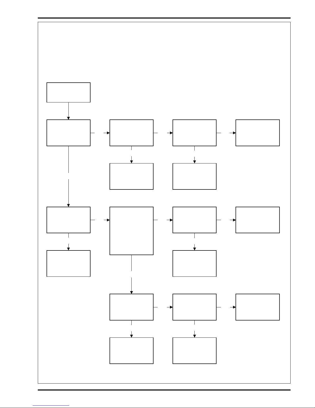
FORM NO. 56043056 ConvertaMAX™ 20/26 / BA 550/650 - 23
SCRUB BRUSH SYSTEM
Scrub brush(es)
don't turn (See
Figure 1).
Check for 24V at
the Neg. K1
Org/Blk coil wire
to a Pos. battery
standoff
Check for 24V at
the Pos. K1 Brn
coil wire to a Neg.
battery standoff
Check for a Pos.
24V at pin #11
(input) on the A2
Module.
Repair or replace
the pin #11 (Vio)
input wire.
Check for 24V (Neg.)
at the pin #4 input on
the A2 timer module.
Note: The control
handle drive paddle
must be activated
(Fwd or Rev) for the
speed control to
close the P1 output
circuit.
Replace the A2
timer module
Check for a Pos.
24V at pin #3
(output) on the A2
Module.
Check for a Neg.
24V at pin #9 on
the A2 timer
module
Yes
Yes
Yes
NoNoNo
Replace the K1
brush motor
solenoid
Repair or
replace the Brn
K1 coil wire
Yes
No
No
Yes
Yes
No No
Yes
Yes
No
Check for a Neg.
24V at the Gra P1
wire on the A1
speed controller
Replace the A1
speed controller
Repair or replace
the P1 controller
(output) wire.
Replace the A2
timer module
assembly
Check for 24V at
the Blk wire on
the S6 brush
switch to a Pos.
battery standoff.
Replace the S6
brush switch
Repair or replace
the Blk S6 brush
switch wire.
SYMPTOM TWO
Brush Motor(s) Don’t Turn
Note: Do all testing with key switch on, brush switch closed (scrub deck lowered) and drive paddle activated (pushed Fwd or pulled into Rev).
Part B: Scrub Brush Motor Control Circuit Troubleshooting Guide
TROUBLESHOOTING GUIDE (CONTINUED)
revised 9/01
Page 25

24 - FORM NO. 56043056 ConvertaMAX™ 20/26 / BA 550/650
SCRUB BRUSH SYSTEM
SYMPTOM THREE
Scrub Brush Auto Removal Function Does Not Work
Note: Do all testing with the key switch ON, scrub deck raised (S6 brush switch open*), drive system in neutral. To remove the scrub brush(es)
simply depress the control panel remove switch S3.
Circuit sequence detail: The S3 switch is closed and the pin# 10 input causes a brief negative output at pin#2 that energizes the K1 solenoid
and the brush motor(s) turn(s) momentarily. Next the A2 timer module de-energizes the solenoid and a negative output from pin #7 passes through
the bottom contacts of the brush solenoid to short the motors to ground.
TROUBLESHOOTING GUIDE (CONTINUED)
*Special Service Note: Before following all the troubleshooting steps shown above test the S6 brush switch with an Ohm meter to confirm an open
circuit. Also check the switch for proper adjustment (raised open/lowered closed).
**Special Service Note: This will be a brief pulse not a continuous voltage.
Yes
No
Yes
No
Yes
No
Scrub brush auto
removal function
does not work (See
Figure 1).
Check for 24V (Neg.)
at pin #10 found on the
A2 timer module. Note:
The S3 Switch must
be activated (closed).
Check for 24V
(Neg.)** at the
Wht/Red wire on the
K1 brush solenoid
(note the S3 switch
must be activated).
Check for 24V
(Neg.) at the Blk
wire on the S3 brush
remove switch
Replace the S3
brush remove
switch
Replace the A2
timer module
Check for a 24V
(Neg.)** at the K1
solenoid wires 12 &
16. This is the circuit
sequence that is
needed to short the
brush motor(s), stop
the motors quickly.
Check solenoid wiring and continuity of
the bottom contacts.
If contacts are open
when the S3 switch
is activated replace
the K1 solenoid.
revised 9/01
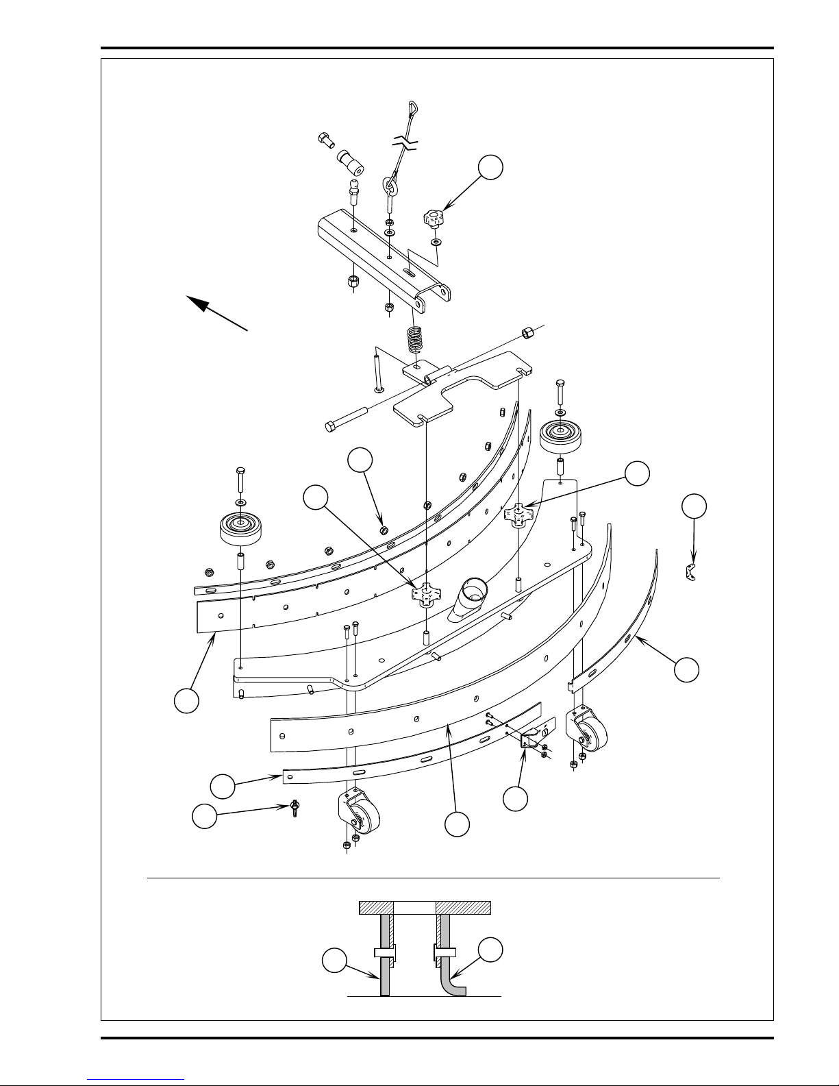
Page 26

FORM NO. 56043056 ConvertaMAX™ 20/26 / BA 550/650 - 25
SCRUB BRUSH SYSTEM
A
FRONT
C
B
E
D
A
E
B
D
C
F
G
H
K
J
I
Solution
Delivery Tube
MODEL CONVERTAMAX™ 20/BA 550 SCRUB DECK REMOVAL
1 Disconnect battery connector assembly in the battery compartment.
2 Remove the brush head cover (held in place by 5 screws).
3 Lower the brush deck to the floor with a brush installed.
4 See Figure 2. Remove the solution delivery hose at the scrub deck solution tube.
5 Remove the hardware items (A,B,C,D & E) from the brush head brackets and lift linkage arms. Note: Do not loose the removable lift arm bushings.
6 Remove (Qty 2) item (F) Hairpins and the (2) (G) Mount Pins from the (upper) scrub head lift linkage.
7 Pull the scrub head forward 12 inches (30 cm) to access the motor wiring terminal block.
8 Remove the motor wiring at the terminal block and then pull the brush head assembly completely from the machine. Note: See Figure 4 for the correct wiring
for the single scrub brush motor.
FIGURE 2
SCRUB BRUSH MOTOR/GEARBOX REMOVAL CONVERTAMAX™ 20/BA 550
1 Follow steps 1-8 of the Scrub Deck Removal section
above.
2 Turn the brush deck over, top of motor down.
3 See Figure 2. Remove the Hex Hd Screw (H) from the
motor output shaft and then pull the Clutch Plate (I) and
drive plate lug assembly (K) off from the shaft. Note: Do
not loose the shaft key.
4 Mark the location of the motor to the brush deck for proper
re-assembly.
5 Remove the (4) (J) Hex Hd Screws securing the motor to
the brush deck and separate.
revised 9/01
Page 27

26 - FORM NO. 56043056 ConvertaMAX™ 20/26 / BA 550/650
SCRUB BRUSH SYSTEM
FRONT
T
S
X
U
Z
W
Y
L
CC
N
O
M
AA
BB
O
M
Q
P
R
V
FRONT
MODEL CONVERTAMAX™ 26/BA 650 SCRUB DECK REMOVAL
1 Follow steps 1-3 in the Scrub Deck Removal section for the ConvertaMAX™ 20.
2 See Figure 3. Remove the Solution Delivery Tube (L) at the solution solenoid valve.
3 Remove the hardware items (M, N, O, P, & Q) from the brush head Support Brackets (R) and lift linkage arms.
4 Remove (Qty 1) item (S) Hairpin and the Mount Pin (T) from the (upper) scrub head lift linkage.
5 Pull the scrub head forward 12 inches (30 cm) to access the motor wiring terminal block.
6 Remove the motor wiring at the terminal block and then pull the brush head assembly completely from the machine. Note: See Figure 4 for the correct
wiring for both the left and right scrub brush motors.
MODEL CONVERTAMAX™ 26/BA 650
SCRUB BRUSH MOTOR/GEARBOX
REMOVAL
1 Follow steps 1-6 in the Model ConvertaMAX™ 26/BA
650 Scrub Deck Removal section.
2 Turn the brush deck over, top of the motors down.
3 Remove the scrub brushes from the brush holders then
mark the location of the motor to the brush deck for proper
re-assembly.
4 See Figure 3. Remove the (3) (U) Hex Screws and (3) (V)
Nuts from each Flexible Coupler (W).
5 Next remove the (3) Hex Lock Screws (X) that connect
the coupler to the Drive Hubs (Y) and remove the brush
holder(s) (Z).
6 Remove the hardware items (AA & BB) that secure the
Hub (Y) to the output shaft on each gearbox. Then pull
the hub from the shaft and save the key.
7 Remove the (4) (CC) Screws and separate the motor/
gearbox assembly from the scrub deck that needs replacement.
8 Re-assemble in reverse order and test for proper opera-
tion. Note: Apply a small amount of grease or a product
called “Never Seize” to the gearbox output shaft when
reinstalling the Drive Hub(s) (Y).
FIGURE 3
revised 9/01
Page 28

FORM NO. 56043056 ConvertaMAX™ 20/26 / BA 550/650 - 27
SCRUB BRUSH SYSTEM
-
+
+
-
+
-
-
+
-
+
-
+
Ri ght*
Brush
Mot o r
Left*
Brush
Mot o r
Brush
Mot o r
Neg. Standoff
Neg. Standoff
To K1 Sol enoid
To K1
Sol enoid
26" Models
20" Models
Neg. Standoff
To K1
Sol enoid
Ri ght *
Brush
Mot o r
Left*
Brush
Mot o r
Wi t hout Jumper Plates With Jumper Plates
-
+
+
-
Jumper Plat es
-
+-+
CW rotation
from shaft end
CCW rotation
from shaft end
CW rotation
from shaft end
CCW rotation
from shaft end
Negative lead from right motor
Negati ve lead from left motor
Posi ti ve lead from ri ght motor
Negative lead from right motor
Nega ti ve lead from left motor
Pos. lead from rt motor
*Right and left are identified as seen from the rear of the machine.
FIGURE 4
revised 10/01
Page 29

28 - FORM NO. 56043056 ConvertaMAX™ 20/26 / BA 550/650
SCRUB BRUSH SYSTEM
11/32"
(8.7 mm) *
A
B
C
7/32"
(5.5 mm) *
A - Brush OFF (Raised Storage Position)
B - Brush ON (Brush Install Position)
C - Brush ON (Normal Scrub Position)
Stri ker Plate
Switch Mount
Bracket
BRUSH HEAD SWITCH ADJUSTMENT (MACHINES BUILT BEFORE MARCH 2001)
WARNING!
Have the master key switch OFF when servicing the brush switch.
1 To access the brush switch remove the (5) screws securing the brush motor shroud then put the scrub brush deck in it’s UP stored position.
2 See Figure 5(A, B & C) below. These illustrations show the correct switch operational positions for the (A) raised storage position, (B) brush install position
and (C) normal scrub position.
3 With the key OFF, scrub deck raised, place scrub brush(es) underneath the drive disc(s) and lower deck for the automatic brush installation.
4 With the brush switch mounted loosely position the switch on the corner of the switch striker plate as shown in figure B. Note: The switch is mounted with
the roller not compressed and is in its normally closed position.
5 Turn the key ON, engage the drive paddle and install the brushes onto the drive disc(s) automatically. Note: The brush motor(s) will run.
6 Raise and lower the brush-head to test the switch for proper switch functions. Up the brush(es) should not run and down the brush should run.
FIGURE 5
*Note: Measurements given are approximate and intended only as a starting point for adjustment.
revised 9/01
Page 30

FORM NO. 56043056 ConvertaMAX™ 20/26 / BA 550/650 - 29
SCRUB BRUSH SYSTEM
FRONT
Front ViewSide View
Scrub deck in
raised position
Scrub deck in
lowered position
FIGURE 6
BRUSH HEAD SWITCH ADJUSTMENT (MACHINES BUILT AFTER FEBRUARY 2001)
WARNING!
Have the master key switch OFF when servicing the brush switch.
1 To access the brush switch remove the (5) screws securing the brush motor shroud then put the scrub brush deck in it’s UP stored position.
2 See Figure 6. Position the switch arm roller on the corner of the striker bracket as shown.
3 Push the switch and roller down to compress the switch (you will hear a click) then tighten the mounting screws to secure the switch adjustment. Note the
switch is now properly adjusted for an open circuit brush motors Off function.
4 Install scrub brush(es), lower the scrub deck, turn the key switch on and then engage the drive paddle to test that the brush motors run. Also cycle raise
and lower the brush deck to check the proper On and Off brush and drive paddle operations.
revised 9/01
Page 31

30 - FORM NO. 56043056 ConvertaMAX™ 20/26 / BA 550/650
RECOVERY SYSTEM
FUNCTIONAL OVERVIEW
Vacuum / Recovery System General
Dirt and water are lifted off the floor into the recovery tank by airflow, created by a 3-Stage 24V vacuum motor. The wastewater and air enter the
vacuum system at the squeegee tool, through small openings (notches) located in the front squeegee blade. The small openings are the entrance
points for the water and air, and help speed up the airflow producing the suction to lift the wastewater off of the floor. The air and wastewater move
through the squeegee hose at high speed until it reaches the recovery tank. There the air slows down because of the increased volume (large
size) of tank. With the decreased air speed the heavier water falls to the bottom of the recovery tank. Then at the same time the airflow continues
through the tank, shutoff float, vacuum hose, vacuum motor and is exhausted out of the vacuum motor housing. No wastewater ever actually moves
through the vacuum motor, just clean air.
The vacuum system uses a shutoff float to prevent the tank from being overfilled and stops any water from being sucked into the vacuum motor.
Vacuum Motor Function
See Figure 2. The K2 vacuum motor solenoid is energized (turned on) when lowering the squeegee raise/lower lever. With the squeegee lever
lowered the S4 vacuum switch is closed and completes the control circuit that energizes K2 solenoid. With the load side of the K2 solenoid output
voltage complete the M1 vacuum motor will run.
Drain Hose
Squeegee
Vacuum Exhaust
Hose
Vacuum Motor
Cover Gasket
Recovery
Tank Cover
Recovery Tank
Squeegee Hose
Float Cage & Ball
Float Duct
FIGURE 1
revised 9/01
Page 32

FORM NO. 56043056 ConvertaMAX™ 20/26 / BA 550/650 - 31
RECOVERY SYSTEM
Electrical Diagram
*For complete description of all callouts see Electrical System Wiring Diagram.
VACUUM / RECOVERY SYSTEM SERVICE MAINTENANCE CHECKLIST
Whenever there is a vacuum problem, it’s best to check over the entire system. Use the checklist below as a guide, to thoroughly check the vacuum
system.
Clean built-up dirt from the inside of the squeegee tool.
Replace the squeegee blades if they are nicked or torn.
Inspect the hose between the squeegee tool and the recovery tank, rinse any built-up dirt from the hose. Replace the hose if it is kinked
or damaged.
Inspect and make sure the gasket on the recovery tank cover is sealing and not damaged.
Inspect and clean the vacuum motor float cage.
Make sure that the recovery tank drain valve seals airtight.
TROUBLESHOOTING GUIDE
If water flows around the ends of the squeegee tool, instead of being pulled into the tool, the vacuum system is not working properly. When a vacuum
system performs poorly, it is usually because of one of the following problems:
Vacuum Leak(s) – Air flowing into the vacuum system past a bad gasket or leaky hose, damaged tank, or a leaky drain valve. A vacuum leak
below the water line will create turbulence in the recovery tank, causing water to enter the vacuum motor.
Restriction(s) – Anything that blocks the flow of air through the system. Restrictions may also be caused by built-up debris in the squeegee tool,
vacuum hoses, float cage or wherever the airflow is forced to make a sharp turn.
Both leaks and restrictions decrease the quantity of air flowing through the squeegee tool. The air that does go through the squeegee tool moves
slower, so it has less pick-up power.
FIGURE 2
F4
+24V -24V
RED/GRNRED
BLK
M
M1
BLU
K2
D1
K2
BLK
RED/WHT
S4
VIO
RED
S5
F1
S1
revised 9/01
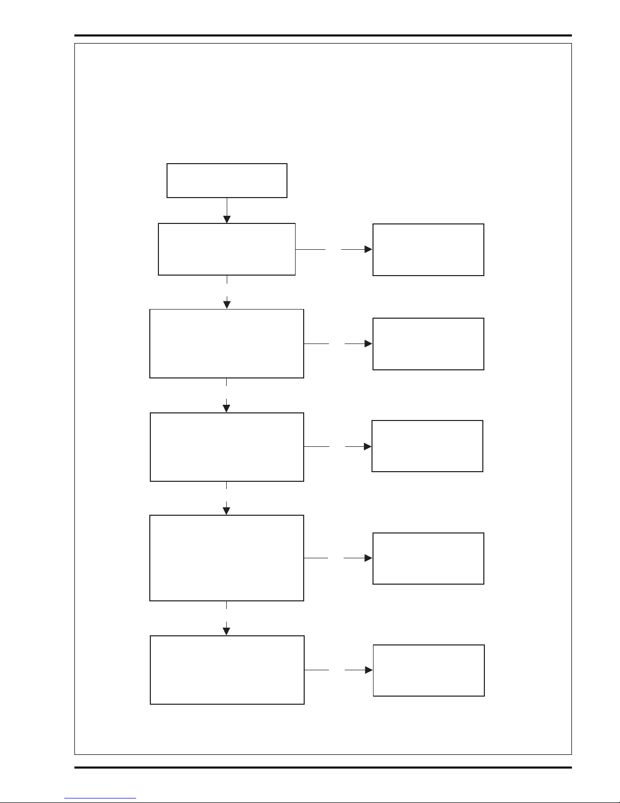
Page 33

32 - FORM NO. 56043056 ConvertaMAX™ 20/26 / BA 550/650
RECOVERY SYSTEM
No
Yes
Yes
Yes
No
No
Vacuum motor will not
run (See Figure 2).
1. Try re-setting the
circuit breaker first.
2. Check continuity on
the F4 (30A) vac
motor circuit breaker
Replace the F4 (30A)
vac motor circuit breaker
Check for 24V at the
blue wire (output
terminal) on the K2 vac
motor solenoid to a Neg.
battery standoff.
Check for 24V at the
M1 vac motor
Repair or replace
the M1 vac motor
See part B vac motor
control circuit
troubleshooting guide.
Repair or replace
wiring to vac motor
TROUBLESHOOTING GUIDE ELECTRICAL
Possible Symptom
1 Vacuum motor will not run
SYMPTOM ONE
Note: Do all testing with the master key switch ON, vac switch S4 ON (squeegee lowered).
Part A: Vacuum Motor Load Circuit Troubleshooting Guide
revised 9/01
Page 34

FORM NO. 56043056 ConvertaMAX™ 20/26 / BA 550/650 - 33
RECOVERY SYSTEM
SYMPTOM ONE
Note: Do all testing with the master key switch ON, vac switch S4 ON (squeegee lowered).
Part B: Vacuum Motor Control Circuit Troubleshooting Guide
TROUBLESHOOTING GUIDE ELECTRICAL (CONTINUED)
No
Yes
Yes
No
No
Yes
No
Vacuum motor
will not run (see
Figure 2).
Check for 24V at
the Red/Wht and
Blk wires on the K2
vac motor solenoid
(small terminals).
Check for 24V at
the (Pos.) K2
Red/Wht solenoid
coil wire to a Neg.
battery standoff
Replace the
K2 vac motor
solenoid
Check for 24V at
the (Neg.) K2 Blk
solenoid coil wire
to a Pos. battery
standoff
Check for 24V at
Vio wire on the
S4 vac switch to a
Neg. battery
standoff
Repair or replace
the Blk wire back
to the Neg. battery
standoff
Replace the S4
vac motor switch
Repair or replace
the Vio wire back
to the S1 key
switch
revised 9/01
Page 35

34 - FORM NO. 56043056 ConvertaMAX™ 20/26 / BA 550/650
RECOVERY SYSTEM
FRONT
A
B
E
C
D
F
G
L
J
H
I
K
M
MAINTENANCE OF FLOAT CAGE AND FLOAT DUCT
1 Open the recovery tank dome lid and lay it to the side, remove the two (A) Screws and pull the Float Duct (B) and float cage assembly (C) from vac motor
spacer (D).
2 Snap apart the two float cage halves (C) and flush clean the float ball and cage pieces.
3 Inspect the Gasket (E) and clean any debris from the inside of the float duct housing. Then re-install all parts in reverse order.
FIGURE 3
revised 9/01
Page 36

FORM NO. 56043056 ConvertaMAX™ 20/26 / BA 550/650 - 35
RECOVERY SYSTEM
12 3
FRONT
Q
O
P
N
1
2
3
R
VACUUM MOTOR REMOVAL
1 Drain the recovery tank using the drain hose.
2 Swing open the recovery tank, secure with prop rod and disconnect the vacuum motor harness connector.
3 See Fig 3. Remove the vacuum motor Duct Cover (F) secured to the bottom of recovery tank bottom (qty 4 screws).
4 Loosen the exhaust hose clamp and remove Hose (M) from the vac motor discharge tube and completely remove the motor from its mount cavity.
5 Inspect the condition of the vac motor Gasket (G) inside the vac motor mount cavity.
6 Make service repairs to the vac motor and re-install by following steps in reverse order.
RECOVERY TANK REMOVAL
1 Follow steps 1-4 in the Vacuum Motor Removal section.
2 See Figure 3. Remove the Nut (H) and release the Tank Support Bar (I) and allow the tank to swing down to the side of the battery compartment box.
3 Loosen the hose clamp for the tank drain hose (J) and pull the hose free.
4 Remove the Tank End Panel (K) (3 screws) and remove the Squeegee Hose (L) from the tank connection.
5 Support the tank and remove the (4) screws from the hinge that attaches the tank to the top of the solution tank edge and pull the tank free from the machine.
VACUUM SWITCH REPLACEMENT AND ADJUSTMENT
1 With the key switch OFF remove the back Electrical Panel (N) secured with (6) screws to access the Vacuum Switch (O) as shown in Figure 4.
2 Remove the (2) Switch Mount Screws (P), Nut Plate (Q) then separate the wiring connector and remove the switch from the machine.
3 With the squeegee Lift Lever (R) in the Up storage position (1) install the vacuum switch loosely to its mount bracket and reconnect the wiring.
4 See Figure 4. Move (push) the switch actuator arm roller against the squeegee lever to where it clicks then tighten the mounting screws.
5 Test with the key switch ON, the vacuum switch is in the open position (off) and the vac motor will not run. Move the squeegee lever to the next notch (2)
and the switch will click to its closed position (on) and the vac motor will run.
FIGURE 4
revised 9/01
Page 37

36 - FORM NO. 56043056 ConvertaMAX™ 20/26 / BA 550/650
SQUEEGEE SYSTEM
SQUEEGEE TOOL BLADE(S) REPLACEMENT
If the squeegee leaves narrow streaks or water, the blades may be dirty or damaged. Remove the squeegee, rinse it under warm water and inspect
the blades. Reverse or replace the blades if they are cut, torn, wavy or worn.
To Reverse or Replace the Rear Squeegee Wiping Blade...
1 See Figure 1*. Raise the squeegee tool off the floor, then unsnap the Center Latch (A) on the squeegee tool.
2 Remove the Wing Nut (B) from each end of the squeegee, then remove the Tension Straps (C).
3 Slip the Rear Blade (D) off the alignment pins.
4 The squeegee blade has 4 working edges. Turn the blade so a clean, undamaged edge points toward the front of the machine. Replace the blade if all
4 edges are nicked, torn or worn to a large radius.
5 Install the blade, following the steps in reverse order and adjust the squeegee.
To Reverse or Replace the Front Squeegee Blade...
1 Raise the squeegee tool off the floor, then loosen the (2) Thumb Nuts (E) on top of the squeegee and remove the squeegee tool from the mount.
2 Remove all the Hex Nuts (F) that hold the Front Blade (G) in place, then remove tension strap and blade.
3 The squeegee blade has 4 working edges. Turn the blade so a clean, undamaged edge points toward the front of the machine. Replace the blade if all
4 edges are nicked, torn or worn to a large radius.
4 Install the blade, following the steps in reverse order and adjust the squeegee.
SQUEEGEE ADJUSTMENT
Adjusting the Squeegee Angle
Adjust the squeegee angle whenever a blade is reversed or replaced, or if the squeegee is not wiping the floor dry.
1 Park the machine on a flat, even surface and lower the squeegee. Push the machine forward enough to have the squeegee wiping blade fold over to the
rear as shown in figure 2.
2 See Figure 1. Turn the Adjustment Knob (H) to tilt the tool forward (CCW) or backwards (CW), until the rear squeegee wiping blade touches the floor evenly
across its entire width.
revised 9/01
Page 38
FORM NO. 56043056 ConvertaMAX™ 20/26 / BA 550/650 - 37
SQUEEGEE SYSTEM
FRONT
H
F
B
C
C
E
A
B
E
D
G
FIGURE 1
FIGURE 2
G
D
*Note the 20” squeegee tool is shown, the 26” squeegee tool is similar in adjustment and blade replacement.
revised 9/01
Page 39

38 - FORM NO. 56043056 ConvertaMAX™ 20/26 / BA 550/650
WHEEL DRIVE SYSTEM
-
+
1
2
3
4
5
6
R1
R2
A1
F3
P1
B-B+
P2
BLK
M
WHT/YEL
RED/BLU
M2
+24V
VIO
RED
S5
F1
S1
RED BRN/BLK
RED/BLKBRN/RED
-24V
VIO
ORN
GRN
YEL
(T1)
(T2)
(T3)
(T4)
M1
M2
GENERAL FUNCTIONAL OVERVIEW
A 1/2 horsepower permanent magnet 24V DC motor drives the ConvertaMAX™ models 20/26 & BA 550/650. See Figure 3. The motor output
is delivered to a single front mounted drive wheel driven by a chain. See Figure 1. The speed of the motor is regulated by a solid-state speed
control (A1), located in the rear handle electrical compartment. The potentiometer (R2), mounted in the drive paddle, regulates both machine
direction and variable speed demands. A second pot (R1) is mounted in the control panel and its knob can be adjusted to control the machines
maximum transport speed.
Drive Motor System Function
See Figure 1. With the key switch S1 closed the violet wire inputs 24V to the A1 speed controller to make it operational (power it up). The F3 (30
Amp) circuit breaker supplies the (Pos.) 24V power input to the T1 or B+ controller terminal (Brn/Blk wire). The black wire from the battery Negative
standoff supplies the (Neg.) 24V power input to the T2 or B- controller terminal. Moving the 5K Ohm R2 speed pot off its centered balanced neutral
setting activates the operator input to the speed control. Forward or reverse movement of the drive paddle rotates the pot shaft and its variable
resistance changes causing internal voltage input signal changes within the controller. These pot voltage related signals then energize the Fwd
and Rev directional relays that selects the motor polarity and final voltage level outputs at the M1 & M2 terminals.
FIGURE 1
Electrical Diagram
*For complete description of all callouts see Electrical System Wiring Diagram.
-
+
1
2
3
4
5
6
WHT
R1
R2
A1
(Partial)
VIO
ORN
GRN
YEL
BRN*
YEL
WHT*
GRN*
ORN
GRN
P1
Key Switch
25K Ohms
5K Ohms
FIGURE 2
This drawing shows additional controller input circuit detail. The R1 pot is shown at the Max speed limiting setting and the R2 pot in neutral.
*Handle wiring harness changed. Machines built after December 1, 2000 have different wire colors at R2 pot. Green wire changed to GRN/YEL,
brown wire changed to BLK #2 (wire with the number 2 printed on it) and white wire changed to BLK #1.
revised 7/02
Page 40

FORM NO. 56043056 ConvertaMAX™ 20/26 / BA 550/650 - 39
WHEEL DRIVE SYSTEM
FRONT
Chain
Drive Wheel
Drive Wheel Motor
R1 Potentiometer
(25,000 Ohms)
R2 Potentiometer
(5,000 Ohms)
WHEEL DRIVE TROUBLESHOOTING GUIDE
Problem Possible Cause
• No forward or reverse wheel drive. See Electrical Troubleshooting Flowcharts A & B.
• No wheel drive in one direction, Controller can’t change electrical polarity to wheel motor.
loss of either forward or reverse. Replace the (A1) speed control.
• Machine creeps (moves) in forward or • Check movement of the drive paddle spring centering device
reverse with only the key switch ON. (auto dead-man return to neutral components). Repair or replace
needed parts.
• The R2 drive pot is out of adjustment. Reset to neutral the 5000
Ohm drive paddle potentiometer (*).
• During normal machine transporting with the 5K The R1 (25,000 Ohm) speed limiting pot wiper is either open
drive paddle pot activated the operator also adjusts where the machine runs at minimum speed or the pot wiper
the control panel maximum speed limiting R1 pot and is shorted and runs at maximum speed. Replace the R1 pot (**).
does not affect the desired maximum machine speed
output.
* See Potentiometer Installation and Adjustment instructions in this manual section and reset the (5K) pot to neutral.
** See 25K Wheel Drive Speed Limit Potentiometer Testing instructions in this manual section.
FIGURE 3
revised 9/01
Page 41

40 - FORM NO. 56043056 ConvertaMAX™ 20/26 / BA 550/650
WHEEL DRIVE SYSTEM
TROUBLESHOOTING GUIDE ELECTRICAL
Possible Symptom
1 No forward or reverse wheel drive
SYMPTOM ONE
Note: Do all testing with control panel R1 speed limiting pot in the maximum position, the drive wheel jacked up off the floor, key switch ON, and
the drive paddle activated (pushed Fwd or pulled into Rev.)
Part A: Wheel drive system motor load circuit troubleshooting guide
Note A: The drive wheel motor harness disconnect is located in the lower rear of the machine frame between the caster wheels.
No Fwd or Rev
wheel drive
(see Figure 1).
1. Try resetting the F3
drive motor circuit
breaker (30 Amp).
2. Still no drive check
the F3 breakers
continuity
Replace the F3
(30 Amp) wheel
drive circuit
breaker
No
Check for 24V at the
A1 speed controllers
Battery Pos. (+) &
Battery Neg. (-)
terminals.
Repair or replace the
battery input wiring to
the A1 speed controller
Separate the motor
wiring harness (see
note A) & check for
controller output volt-
age by activating the
drive paddle. Should
have 24V Fwd & 15V
in Rev.
Repair or replace
the M2 wheel drive
motor
Yes
See part B wheel
drive control circuit
troubleshooting
guide.
No
Yes
No
Yes
revised 9/01
Page 42
FORM NO. 56043056 ConvertaMAX™ 20/26 / BA 550/650 - 41
WHEEL DRIVE SYSTEM
SYMPTOM ONE
Note: Do all testing with control panel R1 speed limiting pot in the maximum position, the drive wheel jacked up off the floor, key switch ON, and
the drive paddle activated (pushed Fwd or pulled into Rev.)
Part B: Wheel drive system motor control circuit troubleshooting guide
Note A: Follow the potentiometer test instructions shown in the wheel drive system section.
Note B: The drive wheel motor harness disconnect is located in the lower rear of the machine frame between the caster wheels.
TROUBLESHOOTING GUIDE ELECTRICAL (CONTINUED)
No Fwd or Rev wheel
drive (see Figure 1).
At the A1 speed controller
check for 24V input, Vio wire
to Negative battery standoff
Repair or replace the
Vio control circuit
input wire.
Check the total resistance of the
drive paddle R2 pot. Remove
wires and measure across the two
outside terminals, should read
4500-5500 Ohms.
Test shows an open
(infinity) replace the R2
potentiometer with P.N.
56397029
Check the total resistance of
the speed limit R1 pot. Remove
wires and measure across the
two outside terminals, should
read approximately 25000
Ohms.
Separate the motor wiring harness
disconnect (see Note B) & check
for controller output voltage by
activating the drive paddle. Should
have 24V in Fwd & 15V in Rev.
Test shows an open
(infinity) replace the R1
potentiometer with P.N.
56397123
Replace the A1
speed controller
Check the functional operation of
the wiper resistance circuits (see
Note A) for both the 5K(R2) pot &
the 25K(R1) pot.
Test measurements should show a
variable resistance within spec. for
each individual pot when the pot
shaft is turned in both directions.
Replace the specified
pot(s) that's measure-
ments show an open
circuit.
Yes
Yes
Yes
Yes
No
No
No
No
No
revised 7/02
Page 43

42 - FORM NO. 56043056 ConvertaMAX™ 20/26 / BA 550/650
WHEEL DRIVE SYSTEM
CHAIN MAINTENANCE
• Every two months check the chain tension, 1/2 inch (13mm) deflection at mid point.
• Once a month check chain for binding and dryness, apply oil to lube the chain links.
• Yearly remove chain, clean and re-oil.
CHAIN REMOVAL AND ADJUSTMENT
Chain Removal:
WARNING!
Disconnect a battery cable at the battery pack before servicing.
1 See Figure 4. Loosen the Lock Nut (A) and back out Bolt (B) several turns to loosen the drive chain tension.
2 Remove the retainer clip from the chain’s master link, separate and remove the chain from the sprockets.
3 To re-install chain loosen the (3) (C) drive motor mount screws and push the drive motor all the way forward. Note: The reason for this step is to shorten
the distance between the sprockets to make it easier to reconnect the master link.
4 Install a new chain and reconnect the master link and tension chain. Service Tip: Attach a cable tie strap to the end of the chain to help guide it between
the sprockets.
Adjustment:
1 Loosen the (3) motor mount Bolts (C) and the adjustment Lock Nut (A) to adjust chain tension.
2 Turn the Adjustment Bolt (B) in (CW) to obtain a 1/2 inch (13mm) chain deflection between the sprockets when moderate pressure is applied to the chain.
3 Tighten the adjustment bolt lock nut, the (3) motor mount bolts and test the drive system for proper operation.
WHEEL DRIVE MOTOR REMOVAL
1 Drain both the recovery and solution tanks, disconnect and remove the batteries and squeegee.
2 Remove the scrub brush head (follow steps in the Scrub Brush System section) from the machine. Then tip the machine on its right side.
3 Disconnect the drive motor wiring connector.
4 See Figure 4. Loosen the Lock Nut (A) and back out Bolt (B) several turns to loosen the drive chain tension.
5 Remove the retainer clip from the chains master link, separate and remove the chain from the sprockets.
6 Remove both the Setscrews (D) from the Drive Motor Sprocket (E) then remove the sprocket from the motor shaft.
7 Support the Drive Motor (F) then remove the (3) motor mount Bolts (C) and remove the motor and Chain Tension Bracket (G) from the machine.
8 Follow steps 1-7 in reverse order to reassemble, then refer to the Chain Adjustment section to retension the chain.
DRIVE WHEEL REMOVAL
1 Remove the scrub brush(es) and squeegee tool from the machine.
2 Press the brush head raise/lower foot pedal all the way forward and also to the left to place the brush head in its maximum service height position.
WARNING!
Never work under machine without safety stands or blocking to support the machine.
3 Block caster wheels and jack front of machine too where the drive wheel is 1-1/2 inches (38mm) off the floor. Service Tip: Place a small automotive type
scissors or bottle jack underneath the scrub brush deck in the middle being careful not to damage solution fittings.
4 Remove the drive chain (follow instructions in the Chain Removal manual section).
5 See Figure 4. Use a 10mm socket and wrench to remove the Hex Screws (H) and Nuts (I) that secure the Axle Retainer Bar (J) to the machine frame. Then
slide the axle bar off the end of the Axle (K) to remove.
6 Pull the drive wheel assembly forward to remove the left side axle end from its side frame-mounting hole. Then maneuver the wheel assembly out from
underneath the machine.
7 Follow steps 1-6 in reverse order to reassemble, then refer to the Chain Adjustment section to retension the chain.
8 Test-drive the machine for proper operation.
revised 9/01
Page 44

FORM NO. 56043056 ConvertaMAX™ 20/26 / BA 550/650 - 43
WHEEL DRIVE SYSTEM
J
I
K
E
D
C
B
A
G
F
FRONT
H
FIGURE 4
revised 9/01
Page 45
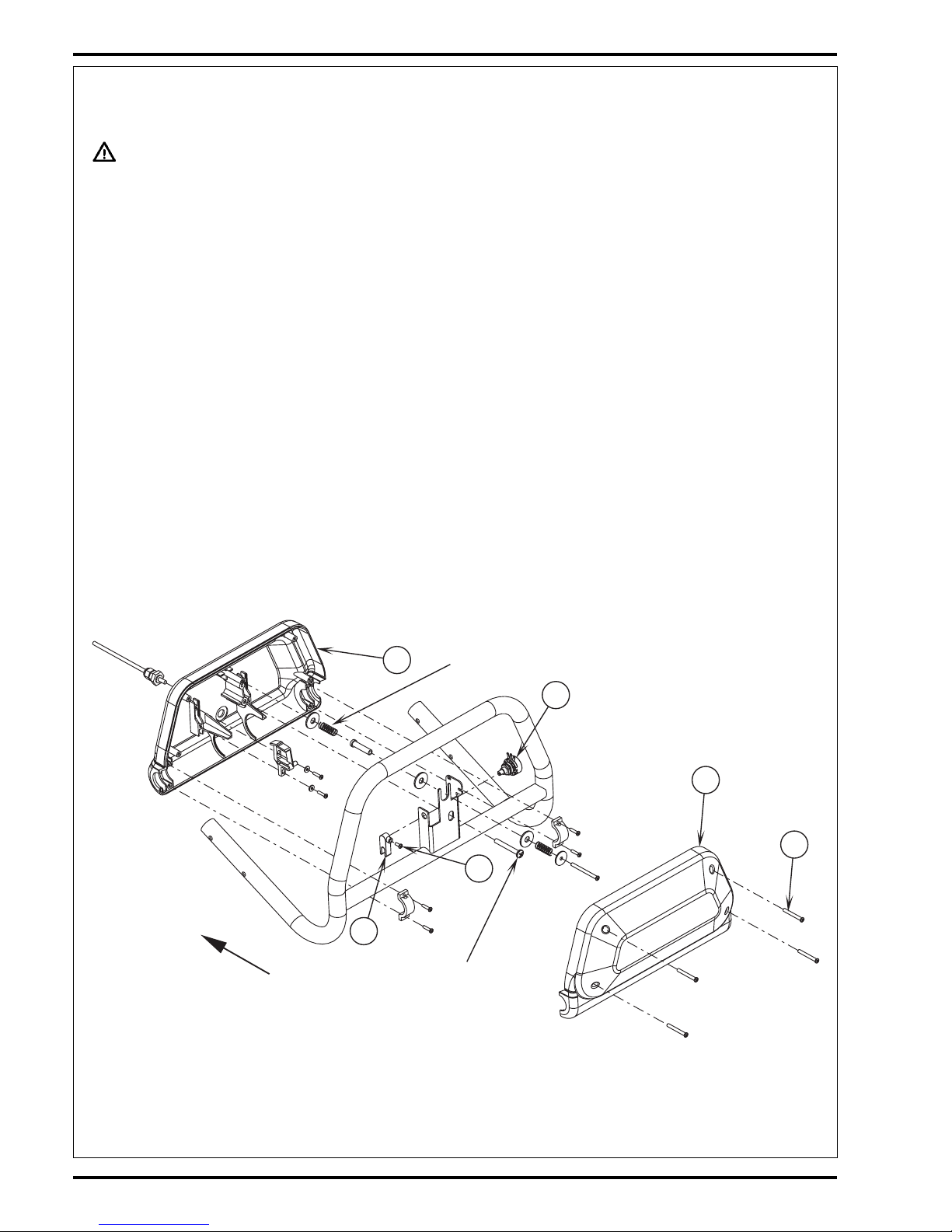
44 - FORM NO. 56043056 ConvertaMAX™ 20/26 / BA 550/650
WHEEL DRIVE SYSTEM
5K POTENTIOMETER TESTING AND REMOVAL (FOR MACHINES BUILT BEFORE DEC. 1, 2000)
WARNING!
Disconnect a battery cable at the battery pack before servicing.
Testing the 5K Potentiometer
Note: The potentiometer (pot) doesn’t have to be removed from its housing mount to test.
1 See Figure 5. Remove the front drive paddle Cover (L) from the rear (back) (M) held together with (4) item (N) Screws.
2 See Figure 6. Observe the 3 wires connected to the pot and disconnect. Note the proper wire numbers and/or colors and their terminal connections for
re-assembly.
3 Test the Pot (O) using an ohmmeter, the potentiometer specification is 5K Ohms. Connect the meter leads to each of the outside connections (1 high &
3 low) on the pot, it should read approximately 5000 ohms (range 4500-5500 ohms).
4 Next, take the 1 high pot connection test lead and connect to the middle connection (2 wiper), then push and pull the rear cover to turn the shaft in both
directions. The readings should be approximately half the total resistance (2500 ohms) towards 5000 ohms and 2500 ohms towards 0 ohms. Example
“A” total resistance of pot 4840 ohms (1 high/3 low) test connections. Example “B” test middle connection (2 wiper) and outside rear (3 low) Fwd reading
2420 ohms to 4700 ohms, Rev 2420 ohms to 230 ohms.
5 Testing Summary: The above tests are to show the increase and decrease of the pot through its working range. If you do not get similar readings replace
the Potentiometer (O).
Potentiometer Removal
6 See Figure 7. Loosen the pot shaft anchor nut and unthread it to the end of the shaft.
7 Back out the Screw (P) from the pot Fork (Q).
8 Maneuver the pot out from its mounting bracket hole and separate the Fork (Q) from the shaft end.
9 Finish unthreading the anchor nut from the end of the pot and then remove the pot completely from the handle mount.
10 To reinstall a potentiometer see the Potentiometer Installation and Adjustment section in this manual system.
revised 7/02
FRONT
M
O
L
N
P
Q
Paddle forward
stop screw
Cent ering springs
(return to neutral)
FIGURE 5
Page 46
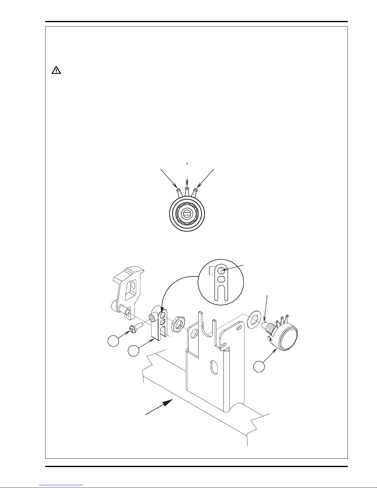
FORM NO. 56043056 ConvertaMAX™ 20/26 / BA 550/650 - 45
WHEEL DRIVE SYSTEM
GRN
WHT
BRN
1
Hi gh
3
Low
2
Wi per
POTENTIOMETER INSTALLATION AND ADJUSTMENT (FOR MACHINES BUILT BEFORE DEC. 1,
2000)
WARNING!
The adjustment of the potentiometer is to set the drive paddle for a neutral drive motor operation. If the potentiometer is not adjusted
properly, the machine could move either FWD or REV with no operator control.
1 See Figure 7. Install the pot into the handle mount hole, then place the washer and anchor nut just threaded a few turns onto the shaft end.
2 Using an ohmmeter connect leads to the middle terminal (2 wiper) and the (3 low pot) outside terminal. Then pre-set, turn the shaft to approximately 2300
ohms.
3 Observe the molded rib inside the Fork (Q) position it to align with the slot on the end of the pot shaft, then assemble together and tighten the (P) Screw.
4 Then without turning the pot shaft thread the anchor nut to seat the pot to its mount bracket.
5 Reconnect the ohmmeter test leads to the pot wiper and low terminal connections and adjust (turn the pot) to obtain half of pots total resistance. This will
accurately set the true neutral drive paddle operator position.
6 Tighten the anchor nut secure. Note: Do not turn the potentiometer shaft when tightening. Reconnect the battery cable and turn the key switch on and
test the drive system for proper FWD and REV operations. Note: The dash panel maximum speed control knob should be turned to the full speed position
for testing.
revised 7/02
FIGURE 6
P
FRONT
Q
O
Rib
Slot
FIGURE 7
Page 47
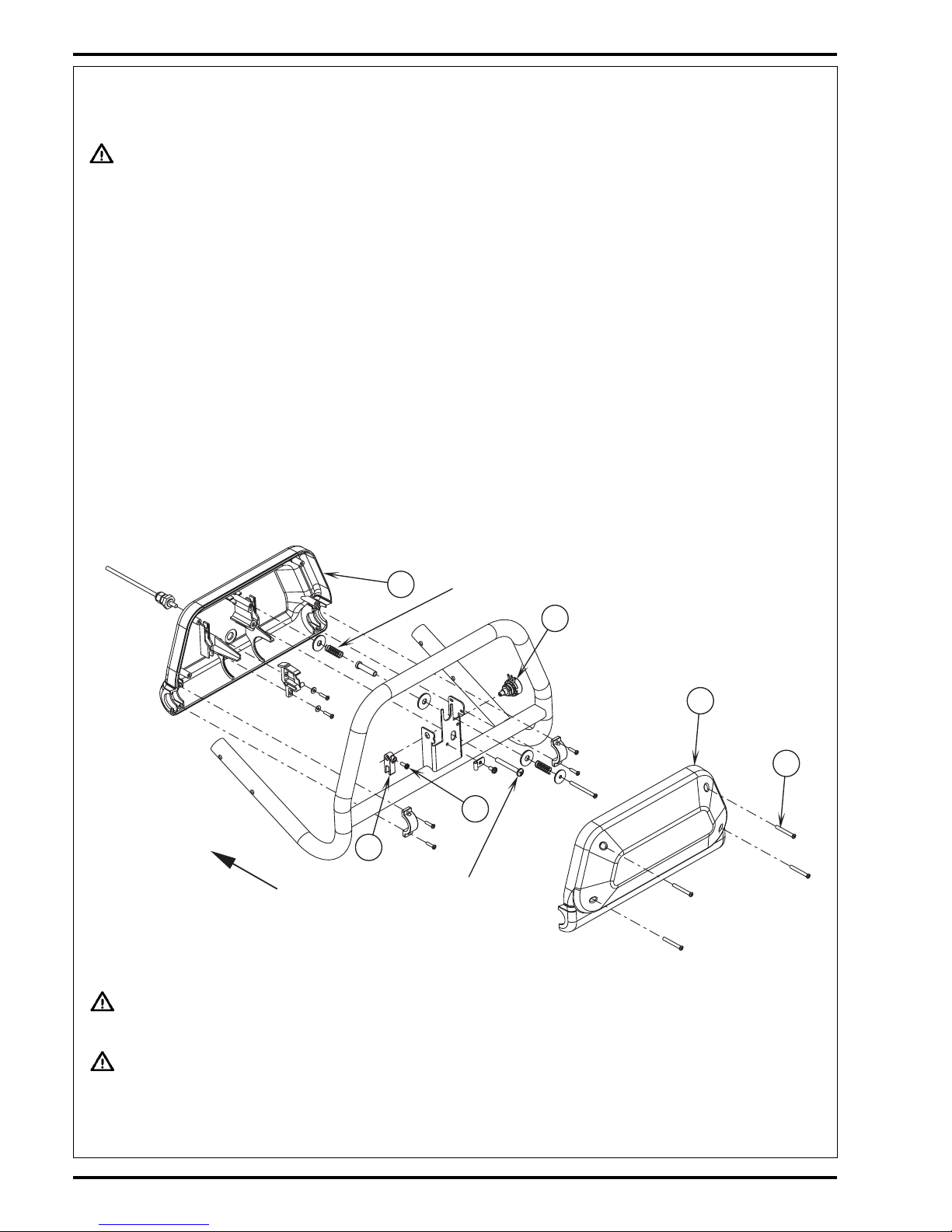
46 - FORM NO. 56043056 ConvertaMAX™ 20/26 / BA 550/650
WHEEL DRIVE SYSTEM
FRONT
M
O
L
N
P
Q
Paddle forward
stop screw
Cent ering springs
(return to neutral)
5K POTENTIOMETER TESTING AND REMOVAL (FOR MACHINES BUILT AFTER DEC. 1, 2000)
WARNING!
Disconnect a battery cable at the battery pack before servicing.
Testing the 5K Potentiometer
Note: The potentiometer (pot) doesn’t have to be removed from its housing mount to test.
1 See Figure 8. Remove the front drive paddle Cover (L) from the rear (back) (M) held together with (4) item (N) Screws.
2 See Figure 9. Observe the 3 wires connected to the pot and disconnect. Note the proper wire numbers and/or colors and their terminal connections for
re-assembly.
3 Test the Pot (O) using an ohmmeter, the potentiometer specification is 5K Ohms. Connect the meter leads to each of the outside connections (1 high &
3 low) on the pot, it should read approximately 5000 ohms (range 4500-5500 ohms).
4 Next, take the 1 high pot connection test lead and connect to the middle connection (2 wiper), then push and pull the rear cover to turn the shaft in both
directions. The readings should be approximately half the total resistance (2500 ohms) towards 5000 ohms and 2500 ohms towards 0 ohms. Example
“A” total resistance of pot 4840 ohms (1 high/3 low) test connections. Example “B” test middle connection (2 wiper) and outside rear (3 low) Fwd reading
2420 ohms to 4700 ohms, Rev 2420 ohms to 230 ohms.
5 Testing Summary: The above tests are to show the increase and decrease of the pot through its working range. If you do not get similar readings replace
the Potentiometer (O).
Potentiometer Removal
6 See Figure 10. Loosen the pot shaft anchor nut and unthread it to the end of the shaft.
7 Back out the Screw (P) from the pot Fork (Q).
8 Maneuver the pot out from its mounting bracket hole and separate the Fork (Q) from the shaft end.
9 Finish unthreading the anchor nut from the end of the pot and then remove the pot completely from the handle mount.
10 To reinstall a potentiometer see the Potentiometer Installation and Adjustment section in this manual system.
FIGURE 8
POTENTIOMETER INSTALLATION AND ADJUSTMENT (MACHINES BUILT AFTER DEC. 1, 2000)
WARNING!
Disconnect a battery cable at the battery pack before servicing.
WARNING!
The adjustment of the potentiometer is to set the drive paddle for a neutral drive motor operation. If the potentiometer is not adjusted
properly, the machine could move in either forward or reverse without any operator input.
1 See Figure 10. Install the pot and washer into the handle mount hole, then tighten the anchor nut.
2 Install the Fork (Q) on the end of the pot shaft and paddle bracket drive pin as shown. Note: Do not tighten the fork/shaft Set Screw (P) at this time.
revised 7/02
Page 48
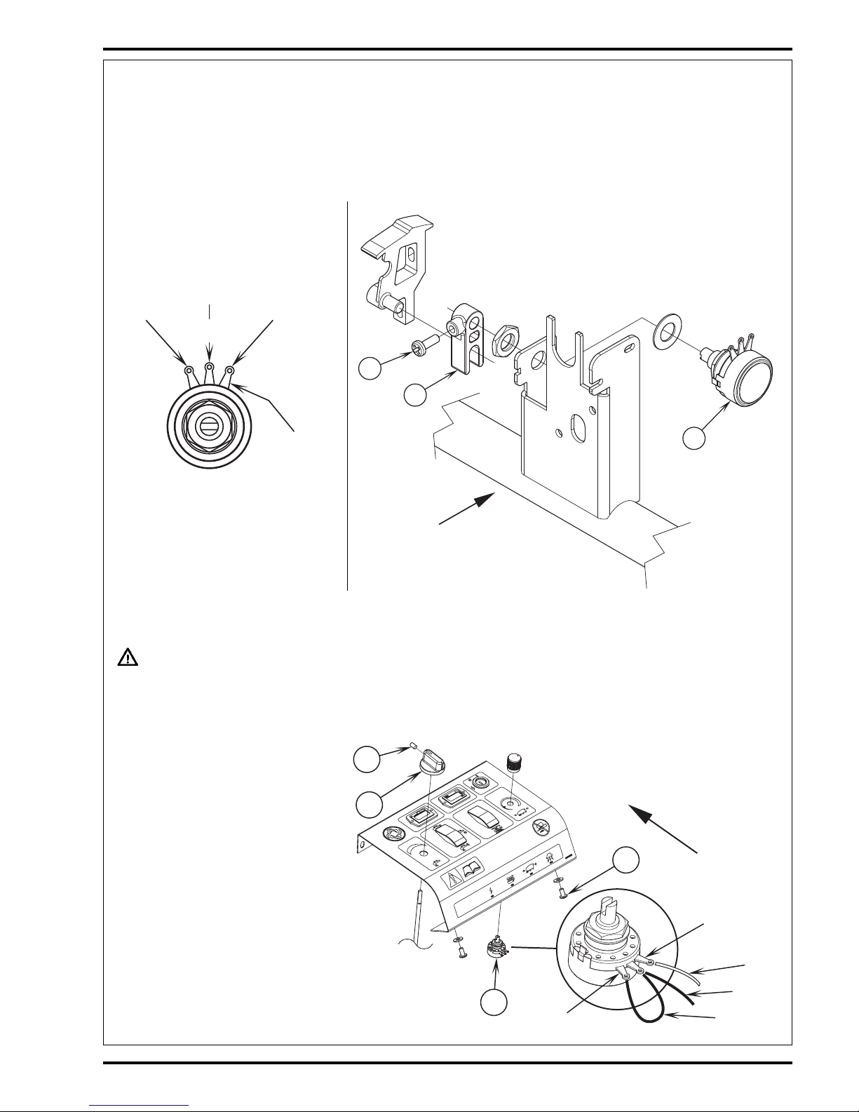
FORM NO. 56043056 ConvertaMAX™ 20/26 / BA 550/650 - 47
WHEEL DRIVE SYSTEM
T
FRONT
U
S
R
High
Low
GRN
GRN
WHT
P
FRONT
Q
O
FIGURE 9
3 Using an ohmmeter connect test leads to the pot wiper (terminal #2) and pot low (terminal #3). Then adjust (turn) pot shaft to obtain half of the R1’s total
resistance. Service Tip: Use a small screwdriver inserted into the end of the fork housing to easily turn the slotted shaft end.
4 Next tighten the (P) Set Screw, being careful not to turn the shaft. Then install the (3) pot wires as shown (Figure 9).
5 Reconnect the battery cable and turn the key switch on and test the drive system for proper Neutral, Forward and Reverse operations. Note: The dash
mounted speed control knob should be turned to its Maximum speed setting.
POTENTIOMETER INSTALLATION AND ADJUSTMENT (AFTER DEC. 1, 2000) (CONTINUED)
25K WHEEL DRIVE SPEED LIMIT POTENTIOMETER TESTING (ALL MODELS)
WARNING!
Disconnect a battery cable at the battery pack before servicing.
Testing the 25K Potentiometer
Note: The potentiometer (pot) doesn’t have to be removed from the instrument panel to test.
FIGURE 11
1 See Figure 11. Remove the Setscrew (R) if
used, from the Solution Control Knob (S) then
pull the knob off from the water valve shaft.
2 Remove the instrument panel, to access the
speed adjustment pot (T), secured with (4) item
(U) Screws as shown.
3 Observe the wires connected to the pot and
disconnect all three. Note the proper wire colors
and their correct terminal connections to reassemble.
4 Test the potentiometer (T) using an ohmmeter,
the specification is 25000 ohms. Connect the
meter leads to each of the outside connections
on the potentiometer, should read approximately
25000 ohms. Next, take one of the test leads and
connect to the middle terminal, then turn the
stem both directions. The resistance value will
change (vary) increasing and decreasing through
its full range of 0-25000 ohms and 25000-0 ohms
approximately. If you do not get similar readings
replace the potentiometer.
revised 7/02
FIGURE 10
GRN/ YEL
wire #1
wire #2
Hi gh
Low
Wi per
123
Terminal #‘s
from stem end
Page 49

48 - FORM NO. 56043056 ConvertaMAX™ 20/26 / BA 550/650
ELECTRICAL SYSTEM
BATTERY SPECIFICATIONS
Use a combination of multiple 2-volt cell units to construct a 24 Volt DC battery pack system.
Nilfisk-Advance recommended battery pack capacity is a 238 AH @ 20 Hour Rate deep cycle battery system. Note: The battery pack must fit the
battery compartment size listed below.
Battery compartment size
Height 13-1/4 inches (33.6 cm)
Width 15.5 inches (39.3 cm)
Length 20-1/2 inches (52 cm)
Maximum battery pack weight 308 lbs. (139 kg)
BATTERY CHARGER SPECIFICATIONS
Use a 24 Volt DC output charger matching the AC input line voltage supply to be used.
Always when selecting a battery charger follow the recommendation of the battery supplier to match the proper charger DC output amperage to
the amp/hour rating batteries being installed. This will prevent the battery pack from being over or under charged.
The recommended 238 AH battery should be matched to a 24V, 20 Amp output charger.
INSTALL THE BATTERIES
WARNING!
Use extreme caution when working with batteries. Sulfuric acid in batteries can cause severe injury if allowed to contact the skin or
eyes. Explosive hydrogen gas is vented from inside the batteries through openings in the battery caps. This gas can be ignited by
any electrical arc, spark or flame.
When Servicing Batteries...
• Remove all jewelry.
• Do not smoke.
• Wear chemical goggles, rubber gloves and a protective apron.
• Work in a well-ventilated area.
• Do not allow tools to touch more than one battery terminal at a time.
CAUTION!
Electrical components in this machine can be severely damaged if the
batteries are not installed and connected properly. Batteries should be
installed by Nilfisk-Advance or by a qualified electrician.
1 Remove the batteries from their shipping crate and carefully inspect them for
cracks or other damage. If damage is evident, contact the carrier that delivered
them or the battery manufacturer to file a damage claim.
2 Turn the Master Key Switch (18) OFF and remove the key.
3 Tip the recovery tank to the side, locked position. Remove the battery cables
from inside the battery compartment.
4 Your machine comes from the factory with enough battery cables to install four
6 volt batteries. Carefully lift the batteries into the battery compartment and
arrange them exactly as shown. Secure the batteries as close to the back of the
machine as possible.
5 The terminals on the battery cables are marked “+” for positive and “-“ for
negative. Install the battery cables as shown, with the terminals marked “+” on
the positive battery terminals and the terminals marked “-“ on the negative
terminals. Position the cables so the battery caps can be easily removed for
battery service.
6 Carefully tighten the nut in each battery terminal until the terminal will not turn on
the battery post. Then tighten the nut one additional turn. Do not over-tighten
the terminals, or they will be very difficult to remove for future service.
7 Coat the terminals and posts with spray-on battery terminal coating (available at
most auto parts stores).
8 Put one of the black rubber boots over each of the terminals.
FIGURE 1
56016653
revised 7/02
Page 50

FORM NO. 56043056 ConvertaMAX™ 20/26 / BA 550/650 - 49
ELECTRICAL SYSTEM
FRONT
TOP OF
MACHINE
LED Indicator Light
Pushbutton
Switch
A1 Timer Module
Assembly
DESCRIPTION OF THE BATTERY LOW VOLTAGE CUTOUT FEATURE
The ConvertaMAX™ 20 & 26 / BA 550 & 650 are equipped with a low voltage cutout feature to prevent over-discharging of the batteries. When
a machines battery pack voltage falls below specifically defined thresholds (voltage settings) the scrub system is automatically shut down. The
cutout level is adjustable. The standard lead acid battery (wet cell) setting is 21 volts (1.75V per cell) and alternate maintenance free battery (gel
cell) setting is 22 volts (1.83V per cell). The standard setting is factory selected and should be used unless the battery manufacturer specifies the
higher cutout voltage. Special Service Note: On all the 24V and 36V machines a minimum recharge voltage of 2.09 volts per cell must be reached
to allow the scrub brush and solution systems (to reset) function again. A 24V-battery pack must increase to a 25.1-volt minimum and a 36V battery
pack to 37.6 volts.
LOW VOLTAGE CUTOUT LEVEL SELECTION
See Figure 2. Have a qualified service technician perform this selection. The cutout level is selected by momentarily depressing the pushbutton
switch located on the module circuit board. Observe the LED indicator light on the circuit board(*), which gives the following indications:
Light OFF No battery power, key is off, or module not functioning
Light ON Slow Flash Alternate maintenance free battery voltage threshold selected (22 volt setting)
Light ON Fast Flash Standard lead acid battery voltage threshold selected (21 volt setting)
Light On Continuous Module is in low voltage cutout mode(**)
*Remove the operator instrument panel to access the LED voltage selection indicator light.
**Scrub brush motor will not operate until batteries are recharged.
Special Battery System Note: It is important to know that the electronic controller module is not connected to the Curtis Battery Fuel Gauge (12).
Therefore, the fuel gauge may or may not be flashing when the module inhibits (shuts down) the brush motor operation depending on the low voltage
cutout threshold selected.
DESCRIPTION OF THE BATTERY FUEL GAUGE
The Battery Fuel Gauge (12) uses a 10 bar LED display that indicates the state of the batteries charge, successively, bar by bar, from full to empty.
At 70% depth of discharge a single flashing light signals an energy reserve alert. At 80% of discharge, a double flashing light signals an empty
alarm. The battery gauge will retain the last state-of-charge condition even when the machine has been turned off. The battery fuel gauge stateof-charge display indication is automatically reset to full charge when the battery pack is recharged.
FIGURE 2
revised 7/02
Page 51

50 - FORM NO. 56043056 ConvertaMAX™ 20/26 / BA 550/650
ELECTRICAL SYSTEM
CHARGING THE BATTERIES
Charge the machines battery pack each time the machine is used, or when the battery fuel gauge (12) is showing red flashing indicator lights. Note:
The machine also uses a special low voltage cutout that inhibits the scrub system see in this manual section the description for the low voltage
cutout feature.
To Charge the Batteries...
1 Push the connector from the charger into the machine Battery Charger Connector port (11) located behind the rear electrical control panel.
2 Follow the instructions on the battery charger.
3 Check the fluid level in all the battery cells after charging the batteries. Add distilled water, if necessary, to bring the fluid level up to the bottom of each
battery cells filler tubes.
WARNING!
Do not fill the batteries before charging.
Only charge batteries in a well-ventilated area.
Do not smoke while servicing the batteries.
CAUTION!
Molded into the floor of battery compartment is a service drain for cleaning. To avoid damage to floor surfaces from a possible acid
leak check that the drain hose is properly attached at both ends and is in good condition.
BATTERY MAINTENANCE
Proper maintenance of electric vehicle batteries can greatly extend their life. Well-maintained batteries may last up to 3 years, but failure after
1 year is common if maintenance has been poor.
There are 3 simple rules for good battery maintenance:
• Maintain Proper Electrolyte Level (Weekly) - Use distilled water in batteries whenever possible. If batteries are discharged, add just enough water to
cover the plates in each cell. If batteries are fully charged, fill each cell to the bottom of the filler tube. Do not over-fill the batteries! Do not add acid
to batteries!
• Keep the Batteries Charged (Weekly) - Batteries should be charged each time that a machine is used for more than 1 hour. Machine operators should
open the battery compartment cover for charging, to avoid a concentrated build-up of hydrogen gas. Operators should follow the instructions provided with
their specific battery charger, to determine how long the batteries should be charged. Even when a machine is stored, the batteries should be charged once
a month to prevent the batteries from “sulfating”. Almost all battery caps are vented, so there’s no need to loosen or remove them for charging.
• Keep the Batteries Clean (Monthly) - Use a damp cloth to wipe dirt from the top of the batteries. Battery terminals must be clean and tight. If the tops
of the batteries are wet after charging, the batteries have probably been over-filled or over-charged. Note: If there is acid on the batteries, wash the tops
of the batteries with a solution of baking soda and water (2) tablespoons of baking soda to 1 quart of water.
BATTERY TESTING
A battery problem is usually recognized by the machine operator, as a decrease in the machine’s running time. This condition is usually caused
by one (or more) “dead cell” in the battery system- that is, one (or more) cell that is putting out less voltage than the other cells.
Note: Always charge batteries before testing.
There are 2 ways to find a dead cell:
• Use a hydrometer to check the specific gravity (or “state of charge”) of the fluid in each cell. A dead cell is one that reads 50 points (or more) lower than
the other cells.
• Use a volt meter to check the voltage of each battery with the scrub drive motor running. The battery with the dead cell will read 1 or 2 volts lower than
the other batteries in the system.
If the batteries in the machine are more than 1 year old, it’s usually best to replace the whole set, rather than replacing just one battery.
revised 7/02
Page 52

FORM NO. 56043056 / CONVERTAMAX™ 20/26 / BA 550/650 - 51
ELECTRICAL SYSTEM
COMPONENT LOCATION
Item Description
1 Speed Control
2Timer Module Assy
3 Fuel Gauge, Battery
4Bracket, Keylock
5 Hourmeter
6Circuit Breaker, 40 Amp (20” model / Brush Motor)
Circuit Breaker, 60 Amp (26” model / Brush Motor)
7Circuit Breaker, 30 Amp (Vac Motor)
8Circuit Breaker, 30 Amp (Wheel Drive Motor)
9Circuit Breaker, 10 Amp (Auxiliary)
10 Contactor, 24 VDC (Vacuum Motor)
11 Contactor, 24V SPDT (Brush Motor)
12 Charge Connector Assy
13 Potentiometer, 25K
14 Potentiometer, 5K
15 Switch, Rocker SPST (Brush Remove)
16 Switch, Vacuum
17 Switch, Toggle (Main Power)
18 Switch, Rocker (Solution)
19 Switch, Interlock
20 Switch, Brush
21 Motor, DC 1/2 HP (Wheel Drive)
22 Motor (20” model / Brush)
23 Motor (26” model / Brush)
24 Motor Assembly (Vacuum)
25 Solenoid Valve Assy (Solution)
26 Battery Connector Assy (in battery compartment)
25
12
19
16
14 11
10
1
2
7
6
8
9
13
17
15
4
53
18
22
24
23
21
20
26
revised 7/02
Page 53

ELECTRICAL SYSTEM
52 - FORM NO. 56043056 / CONVERTAMAX™ 20/26 / BA 550/650
WIRING DIAGRAM / SCHEMATIC
Item Qty Description
A1 1 Speed Control
A2* 1 Timer Module Assy
BT Battery, 24V
D1 1 Diode
D2 1 Diode
F1 1 Circuit Breaker, 10 Amp (Auxiliary)
F2 1 Circuit Breaker, 40 Amp (20” model / Brush Motor)
1Circuit Breaker, 60 Amp (26” model / Brush Motor)
F3 1 Circuit Breaker, 30 Amp (Wheel Drive Motor)
F4 1 Circuit Breaker, 30 Amp (Vac Motor)
K1 1 Contactor, 24V SPDT (Brush Motor)
K2 1 Contactor, 24 VDC (Vacuum Motor)
L1 1 Solenoid Valve Assy
M1 1 Vac Motor Assembly
M2 1 Wheel Drive Motor
M3 1 Motor (20” model)
1 Motor / Gear Unit (26” model)
M4 1 Motor / Gear Unit (26” model)
P1 1 Fuel Gauge, Battery
P2 1 Hourmeter
R1 1 Potentiometer, 25K
R2 1 Potentiometer, 5K
S1 1 Switch, Toggle (Main Power)
S2 1 Switch, Rocker (Solution)
S3 1 Switch, Rocker SPST (Brush Remove)
S4 1 Switch, Vacuum
S5 1 Switch, Interlock
S6 1 Switch, Brush
*Terminal Identification of A2 Timer Module Assembly
1 Relay Common
2 Pad Contactor Coil (+)
3 Pad Contactor Coil (-)
4 Speed Control Input
5 Battery (-)
6 Battery (-)
7 Relay Normally Open
8 Relay Normally Closed
9Brush Switch Input
10 Remove Switch Input
11 Battery (+)
12 Battery (+)
revised 7/02
NO
C
VIO
VIO
RED 25
RED
RED
BRN/BLK
VIO
BRN/RED
F3
S5
F1
BRN/RED
RED/BLK
GRA
S4
S1
RED/WHT
VIO
P1
B+
B-
1
2
P2
B+
B-
(T2)
(T1)
(T3)
-
+
V
h
30
31
BT
1
K2
D1
4
WHT/YEL
VIO
BLK
3
4
1
2
A1
3
P2
2
P1
VIO/BRN
M
1
2
3
4
5
6
M1
+ WHEN
FORWARD
(T4)
M2
GRN
RED/BLU
ORN
YEL
BLK
BLK
26 BLK
BLK
M2
M
M
NO
C
S2
VIO/BLK
A2
YEL/WHT
BLK
BLK
K1
L1
YEL/BLK
S3
WHT/RED
S6
M4
12
ORN/BLK
ORN/BLK
10
VIO/BLK
16
BLK
R2
BRN
BLK
BRN/WHT
M3
R1
BRN
BLK
16
BLK
8
WHT/RED
12
BLK
BLK/YEL
BRN/WHT
BLK
5124
3
10
61
1198
VIO
7
VIO
VIO
2
GEL.
LIQ.
BATTERY
GRA
SWITCH
M
D2
BLK
VIO/BLK
RED/GRN
M1
VIO/BLK
K2
BLU
14
F2
RED
F4
10
BLK
6
4
5
2
3
1
BLK
BLK
Page 54

FORM NO. 56043056 / CONVERTAMAX™ 20/26 / BA 550/650 - 53
ELECTRICAL SYSTEM
revised 7/02
-
+
V
h
12
34
12
3
4
1
6
7
12
BRN/WHT 19A-A
BLK OJ-B
ORN/BLK 30A-B
BRN 1B-B
GRA 8A-B
BLK OC-B
BLK OD-B
WHT/RED 92A-B
VIO/BLK 70A-A
VIO 7C-B
VIO 7G-A
RED 2A-A
RED 2B-A
RED 2C-A
BLK OA-A
BLK OB-A
BLK OC-A
BLK OD-A
BLK OE-A
BLK OJ-A
BLU 6A-B
BLK OB-B
WHT/YEL 94A-B
RED/BLU 26A-B
BATTERY
FUEL
GAUGE
14
8
12
12
HOUR
METER
MAIN
SWITCH
C.B. 10 AMP
(AUXILIARY)
C.B. 60 AMP (26")
C.B. 40 AMP (20")
(SCRUB SYSTEM)
C.B. 30 AMP
(WHEEL DRIVE)
C.B. 30 AMP
(VACUUM)
BRN/RED 12A-B
VIO 7D-B
VIO 7E-B
BLK 0H-A
BLK 0I-A
VIO 7E-A
VIO 7F-A
VIO/BRN 71A-A
BLK 0G-B
BLK 0H-B
RED/BLK 20A-A
VIO 7A-B
VIO 7B-B
VIO 7D-A
RED 2C-B
BRN/RED 12A-A
BRN/RED 12B-A
10
14
RED 2A-B
BRN/BLK 10A-A
RED 2B-B
RED/GRN 25A-B
YEL/BLK 40A-A
YEL/WHT 49A-A
BLK 0F-A
BLK 0G-A
BLK/YEL 04A-B
VIO 7B-A
VIO 7C-A
VIO/BLK 70B-A
S2
SOLUTION
SWITCH
BRUSH OFF
SWITCH
MAXIMUM
THROTTLE
POTENTIOMETER
R1
S3
CONTROL
MODULE
A2
BLK 0I-B
BRN/WHT 19A-B
VIO/BLK 70B-B
VIO/BLK 70D-A
GRN 5B-A
GRN 5B-B
GRN 5A-B
WHT 9A-A
BATTERY
24 Vdc
VACUUM
MOTOR
(+) STAND OFF
(-) STAND OFF
WHEEL DRIVE
MOTOR
(M4 26" ONLY)
SCRUB
BRUSH
MOTORS
BRUSH
MOTOR
SWITCH
INTERLOCK
SWITCH
VACUUM
SWITCH
THROTTLE
POTENTIOMETER
RED/BLU 26A-A
WHT/YEL 94A-A
BRN/BLK 10A-B
BLK 0A-B
GRA 8A-A
VIO 7A-A
ORN 3A-A
GRN 5A-A
YEL 4A-A
SPEED
CONTROL
+ WHEN
FORWARD
P1
P2
(T3)
M1
(T4)
M2
B+
(T1)
B-
(T2)
B+
B-
1
2
1
2
3
4
5
6
ORN 3A-B
BRN
GRN
WHTWHT 9A-B
YEL 4A-B
YEL/BLK 40A-B
YEL/WHT 49A-B
BLK 0F-B
BLK 0E-B
BLU 6A-A
RED/GRN 25A-A
RED/WHT 29A-A
ORN/BLK 30A-A
BLK/YEL 04A-A
VIO/BRN 71A-B
16
10
BRN 1B-A
WHT/RED 92A-A
BRUSH MOTOR
SOLENOID
DIODE
VACUUM
MOTOR
SOLENOID
SOLUTION
SOLENOID
RED/WHT 29A-B
VIO 7H-A
RED/BLK 20A-B
BRN/RED 12B-B
VIO/BLK 70C-A
BLK 0K-B
8
16
M
M
M
M
D2
F2
F3
F4
S1
F1
A1
R2
BT
M1
M2
M4
M3
S6
S5S4
L1
K2
D1
K1
2
5
6
4
3
1
25
26
31
30
ORN 3A-B
#2
GRN/YEL
#1WHT 9A-B
YEL 4A-B
R2
Wire colors at R2 after
December 1, 2000
THROTTLE
POTENTIOMETER
Page 55

DANMARK
Nilfisk-Advance Nordic A/S
Sognevej 25 - Box 344
DK-2605 Broendby
43 23 83 50 – Fax 43 42 15 95
NORGE
Nilfisk-Advance AS
Enebakkvn, 119, 0680 Oslo, Postboks 196, Manglerud,
0612 Oslo
22 08 63 50 – Fax 22 08 63 63
Distriktsrepresentanter over hele landet
SVERIGE
Nilfisk-Advance AB
Sjöbjörnsvägen 5, 117 67 Stockholm
085 55 944 00 – Fax 085 55 944 30
FINLAND/ SUOMI
BERNER Ltd. Facotek Department
Etäleranta 4B, 00130 Helsinki
+358 9 1345 1382
AUSTRALIA
Nilfisk-Advance Pty. Ltd.
ACN 003 762 623
Head office: 17 Leeds Street, Rhodes, N. S. W. 2138
(02) 9736 1244 – Fax (02) 9736 3910
Customer Responce Centre:
1 800 011 013
BELGIQUE / BELGIË/ LUXEMBOURG
Nilfisk-Advance s.a./n.v.
Doornveld/ Sphere Business Park
Industrie Asse 3, nr 11 – bus 41
1731 Zellik-Asse
(02) 467.60.50 Fax (02) 463.44.16
CANADA
Nilfisk-Advance Ltd.
396 Watline Avenue
Mississauga, Ontario L4Z 1X
(905) 712-3260 – Fax (905) 712-3255
DEUTSCHLAND
Nilfisk-Advance AG
Siemensstraße 25-27
25462 Rellingen
(041 01) 3990 – Fax ( 04101) 399191
Zentraler Kundenservice
für die Industrie: 0180 535 67 97
Institutionen und Gebäudereiniger: 0180 500 11 70
FRANCE
Nilfisk-Advance S.A.
BP 246
91944 Courtaboeuf Cedex
(01) 69.59.87.00 Télécopie (01) 69.59.87.01
HONG KONG
Nilfisk-Advance Ltd.
2001, 20/F HK Worsted Mills
Industrial Building
31-39 Wo Tong Tsui Street
Kwai Chung, N.T.
2427 59 51 – Fax 2487 5828
IRELAND
Nilfisk-Advance Ltd.
28 Sandyford Office Park
Dublin 18
+353 1 2943838 – Fax +353 1 2943845
JAPAN
Nilfisk-Advance Inc.
3-4-9 Chigasaki Minami
Tsuzuki-Ku Yokohama 224
045-942-7741 – Fax 045-942-6545
MALAYSIA
Nilfisk-Advance Sdn Bhd
Lot 2, 1st. Floor
Lorong 19/1A
46300 Petaling Jaya
Selangor Darul Ehsan
03-7568188 / 03-7568189 / 03-7568388 – Fax 03-7566828
NEDERLAND
Nilfisk-Advance B.V.
Flevolaan 7, Postbus 341
1380 AH Weesp
0294-462121 – Fax 0294-430053
NEW ZEALAND
Nilfisk-Advance Limited
477 Great South Road, Penrose
Auckland
(09) 525 0092 – Fax (09) 525 6440
SCHWEIZ / SUISSE
Nilfisk-Advance AG
Ringstrasse 19, 9533 Kirchberg/Wil
719 23 52 83 – Fax 719 23 84 44
SINGAPORE
Nilisk-Advance Pte. Ltd.
22, Woodlands Industrial Park E1
Singapore 757740
(65) 759 9100 – Fax (65) 759 9133
TAIWAN
Nilfisk-Advance Ltd.
1 F, No.23, Lane 132, Sec. 2
Ta An Road, Taipei
700 22 68 – Fax 784 08 43
UNITED KINGDOM
Nilfisk-Advance Limited
Newmarket Road
Bury St. Edmunds
Suffolk IP 33 3SR
(01284) 763163 – Fax (01284) 750562
USA
Nilfisk-Advance Inc.
14600 21st Avenue North
Plymouth, MN 55447-3408
+1 800 989 2235 – Fax 1 800 989 6566
Nilfisk-Advance of America, Inc.
300 Technology Drive
Malvern, PA 19355
(610) 647 647-6427
ÖSTERREICH
Nilfisk-Advance GmbH
Vorarlberg Allee 46
1230 Wien
1 616 58 30 – Fax 1 616 58 30 40
ESPAÑA
Nilfisk-Advance, S.A.
Torre D’Ara
Passeig del Rengle, 5 PI.9-10
E-08302 – Mataró (Barcelona)
Tel. 93 741 24 00 – Fax: 93 757 80 20
Central atención al cliente: 902 200 201
nilfisk@nilfisk-advance.es – www.nilfisk-advance.com
Distribuidores y Servicio Técnico en toda España y
Andorra
ITALIA
Nilfisk-Advance Italia Spa
Località Novella Terza
26862 Guardamiglio (LO)
Italy
+39 0377 414067-54 – Fax +39 0377 414097
www.nilfisk-advance.com
PORTUGAL
Nilfisk-Advance Lda.
Rua Cândido de Figueiredo, 91-i, 1500-133 LISBOA
01/7784142 – Fax 01/7785613
Porto 02/526766 – Fax 02/520739
Açores 096/628092/3 – Fax 096/628129
Madeira 091/228965 – Fax 091/228796
GREECE
Embiom S.A.
§ÂˆÊ. µÔùÏÈ·Á̤Ó˘ 60
∞ÚÁùÚÔ‡ÔÏË
164 52 ∞õ‹Ó·
☎ 9950613 - Fax 9951680
www.nilfisk-advance.com
© 2002 Printed in USA
 Loading...