

Page 1
Condor XL
™
Service Manual
Advance Models:
56110000(LPG/48”), 56110001(Petrol/48”), 56110002(Diesel/48”), 56110003(LPG/60”),
56110004(Petrol/60”), 56110005(Diesel/60”), 56110006(LPG/62”), 56110007(Petrol/62”),
56110008(Diesel/62”), 56110009(LPG/67”), 56110010(Petrol/67”), 56110015(Diesel/67”)
56111035(LPG-AXP/48”), 56111036(Petrol-AXP/48”), 56111037(Diesel-AXP/48”)
56111038(LPG-AXP/60”), 56111039(Petrol-AXP/60”), 56111040(Diesel-AXP/60”)
56111041(LPG-AXP/62”), 56111042(Petrol-AXP/62”), 56111043(Diesel-AXP/62”)
56111044(LPG-AXP/67”), 56111045(Petrol-AXP/67”), 56111046(Diesel-AXP/67”)
7/09 FORM NO. 56043124
Page 2

Page 3

TABLE OF CONTENTS
SAFETY INSTRUCTIONS ....................................................................................................................................................4
GENERAL INFORMATION ...............................................................................................................................................5-7
DIAGNOSTIC AND SERVICE TOOLS ..............................................................................................................................8-9
TECHNICAL SPECIFICATIONS ...................................................................................................................................10-13
MAINTENANCE ............................................................................................................................................................14-19
PM CHECKLIST ............................................................................................................................................................20-21
KNOW YOUR MACHINE...............................................................................................................................................22-24
CONTROL PANEL ............................................................................................................................................................24
CONTROL PANEL DIAGNOSTICS ..............................................................................................................................25-26
ELECTRICAL SYSTEM.................................................................................................................................................27-40
FAULT CODE SYSTEM DIAGNOSTICS ..........................................................................................................................27
MAIN CONTROL BOARD FAULT CODES ..................................................................................................................28-31
ENGINE ELECTRICAL COMPONENT LOCATIONS – GM 1.6 GASOLINE ....................................................................32
ENGINE ELECTRICAL COMPONENT LOCATIONS – GM 1.6 LPG ...............................................................................33
ENGINE ELECTRICAL COMPONENT LOCATIONS – KUBOTA DIESEL .......................................................................34
ELECTRICAL COMPONENT LOCATIONS .................................................................................................................35-37
CONTROL BOARD CONNECTORS ...........................................................................................................................38-40
ADJUSTMENTS/REPAIRS ...........................................................................................................................................41-46
SIDE BROOM LIFT ACTUATOR MOTOR ADJUSTMENT ...............................................................................................41
BRAKE TENSION ADJUSTMENT .................................................................................................................................... 42
FOOT PEDAL/HYDROBACK OVERVIEW & NEUTRAL ADJUSTMENT ....................................................................42-43
PUSH/PULL CONTROL CABLE REPLACEMENT ........................................................................................................... 44
HYDROBACK REPLACEMENT .......................................................................................................................................45
FOOT PEDAL NEUTRAL DEADBAND ADJUSTMENT .................................................................................................... 45
SIDE BRUSH TILT ADJUSTMENT ...................................................................................................................................46
TRACTION DRIVE MOTOR HOSE ROUTING ................................................................................................................. 46
GENERAL MACHINE TROUBLESHOOTING GUIDE TABLE OF CONTENTS ...............................................................47
TROUBLESHOOTING GUIDES ..................................................................................................................................48-61
CONTROL BOARD PROGRAMMING OPTIONS ......................................................................................................... 62-66
ENGINE SYSTEM .........................................................................................................................................................67-72
ENGINE SPECIFICATIONS..............................................................................................................................................67
MISCELLANEOUS ENGINE INFORMATION ...................................................................................................................68
GM 1.6L GASOLINE FUEL SYSTEM DESCRIPTION......................................................................................................68
ENGINE DIAGNOSTICS .............................................................................................................................................69-70
1.6L DTC CODES .............................................................................................................................................................71
GM 1.6L ENGINE FUSE BOX & WIRING .........................................................................................................................72
HYDRAULIC SYSTEM ..................................................................................................................................................73-83
HYDRAULIC SYSTEM COMPONENTS ........................................................................................................................... 73
HYDRAULIC COMPONENT LOCATION
HYDRAULIC CYLINDERS ............................................................................................................................................. 74
HYDRAULIC MOTORS..................................................................................................................................................75
HYDRAULIC PUMPS ....................................................................................................................................................76
HYDRAULIC VALVE BLOCK/MANIFOLD .....................................................................................................................77
HYDRAULIC SYSTEM TROUBLESHOOTING ................................................................................................................77
TEST PORT NOMINAL PRESSURE READINGS .......................................................................................................78-79
SCRUB LIFT CYLINDER OVERVIEW ..............................................................................................................................80
HYDRAULIC TRUTH TABLE ............................................................................................................................................81
HYDRAULIC MANIFOLD ASSEMBLY COMPONENT LOCATION KEY .....................................................................81-82
APPENDIX .....................................................................................................................................................................84-98
ELECTRICAL INPUT/OUTPUT TABLE .......................................................................................................................84-87
FAULTS ............................................................................................................................................................................. 88
SOLUTION FLOW DIAGRAM – STANDARD WITH RIGHT FRONT SCRUB .................................................................. 89
SOLUTION FLOW DIAGRAM – ACCESSORIES .............................................................................................................90
SOLUTION FLOW DIAGRAM – AXP................................................................................................................................91
SOLUTION FLOW DIAGRAM – EXTENDED SCRUB .....................................................................................................92
HYDRAULIC SCHEMATIC .........................................................................................................
WIRING DIAGRAM ......................................................................................................................................................94-95
WIRING SCHEMATIC ..................................................................................................................................................96-97
ENGINE HARNESS GM 1.6L GAS ...................................................................................................................................98
ENGINE HARNESS GM 1.6L LPG ...................................................................................................................................99
WIRING HARNESS COMPONENT DESCRIPTION ......................................................................................................100
SWITCH SEQUENCES FOR MAIN CONTROLLER PROGRAMMING OPTIONS ........................................................101
......................................93
FORM NO. 56043124 - Condor XL™ - 3
Page 4
CAUTIONS AND WARNINGS
SYMBOLS
Advance uses the symbols below to signal potentially dangerous conditions. Always read this information carefully and take the necessary steps to protect personnel and property.
DANGER!
Is used to warn of immediate hazards that will cause severe personal injury or death.
WARNING!
Is used to call attention to a situation that could cause severe personal injury.
CAUTION!
Is used to call attention to a situation that could cause minor personal injury or damage to the machine or other property.
Read all instructions before using.
GENERAL SAFETY INSTRUCTIONS
Specifi c Cautions and Warnings are included to warn you of potential danger of machine damage or bodily harm.
DANGER!
* This machine emits exhaust gases (carbon monoxide) that can cause serious injury or death, always provide adequate ventilation
when using machine.
WARNING!
* This machine shall be used only by properly trained and authorized persons.
* While on ramps or inclines, avoid sudden stops when loaded. Avoid abrupt sharp turns. Use low speed down hills. Clean only
while ascending (driving up) the ramp.
* To avoid hydraulic oil injection or injury always wear appropriate clothing and eye protection when working with or near hydraulic
system.
* Turn the key switch (50) off (O) and disconnect the batteries before servicing electrical components.
* Never work under a machine without safety blocks or stands to support the machine.
* Do not dispense fl ammable cleaning agents, operate the machine on or near these agents, or operate in areas where fl ammable
liquids exist.
* Do not clean this machine with a pressure washer.
CAUTION!
* This machine is not approved for use on public paths or roads.
* This machine is not suitable for picking up hazardous dust.
* Use care when using scarifi er discs and grinding stones. Advance will not be held responsible for any damage to fl oor surfaces
caused by scarifi ers or grinding stones.
* When operating this machine, ensure that third parties, particularly children, are not endangered.
* Before performing any service function, carefully read all instructions pertaining to that function.
* Do not leave the machine unattended without fi rst turning the key switch (50) off (O), removing the key and applying the parking
brake.
* Turn the key switch (50) off (O) before changing the brushes and before opening any access panels.
* Take precautions to prevent hair, jewelry or loose clothing from becoming caught in moving parts.
* Use caution when moving this machine in below-freezing temperature conditions. Any water in the solution or recovery tanks or
in the hose lines could freeze.
* Before use, close and latch all doors and hoods.
SAVE THESE INSTRUCTIONS
4 - FORM NO. 56043124 - Condor XL
™
Page 5
INTRODUCTION
Service Manual Purpose
This manual is a technical resource that Nilfi sk-Advance expects to be utilized when servicing a Condor XL. It contains information deemed neces-
sary to provide basic troubleshooting, maintenance and repairs within a reasonable timeframe (example - 2-3 hours). If your repair involves multiple
visits to repair the same problem, or the repair cannot be completed within 3-4 hours, a call to Nilfi sk-Advance Technical Support is needed to alert
the factory to potential issues and/or provide the customer with an acceptable level of service. Refer to the website
ditional information not contained herein as well updates or expanded instructions to procedures noted here.
Note: Bold numbers in parentheses in text indicate an illustrated item.
Note: All references to right, left, front and rear in this manual are as seen from the operator’s position (seat).
General Machine Description
The Condor XL machines are industrial automatic rider sweeper/scrubbers with multiple sweep/scrub single pass coverages. All models use dual
cylindrical scrub brooms with variable scrub pressure and solution fl ow rates. Different models are available with front mounted side brooms (single
and dual) and right side disc scrub.
Parts and Service
Repair should be performed by an Authorized Nilfi sk-Advance Service Center that employs factory-trained service personnel and maintains an
inventory of Nilfi sk-Advance original replacement parts and accessories.
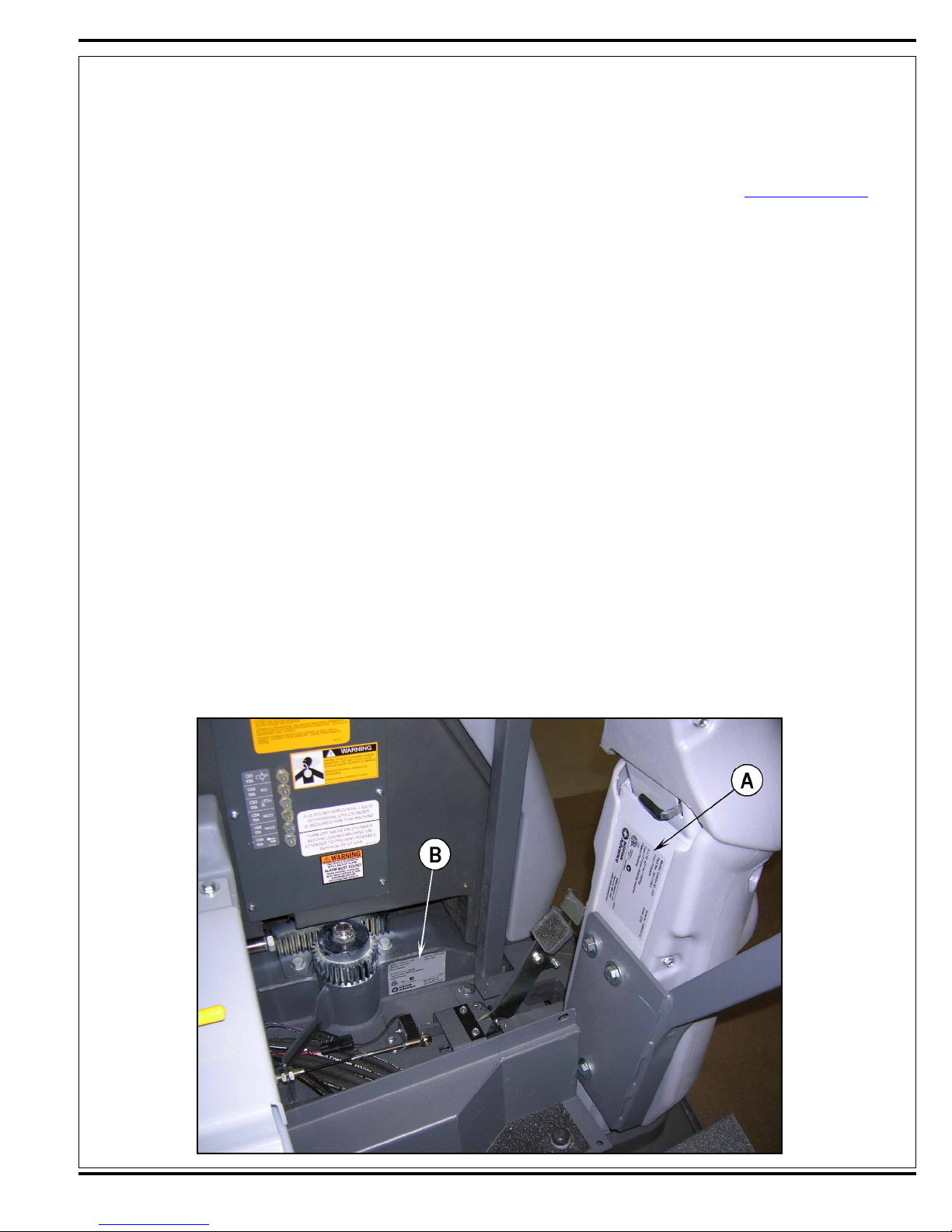
Nameplate
See Figure 1. The Model Number and Serial Number of the machine are shown on the nameplate (A) located on the steering column support, and
on a second nameplate (B) beneath the fl oor plate attached to steering spindle support.
www.advance-us.com for ad-
MODEL NUMBER ________________________________________________
SERIAL NUMBER ________________________________________________
This information is required when ordering repair parts for the machine or contacting Nilfi sk-Advance Technical Support.
FIGURE 1
FORM NO. 56043124 - Condor XL™ - 5
Page 6
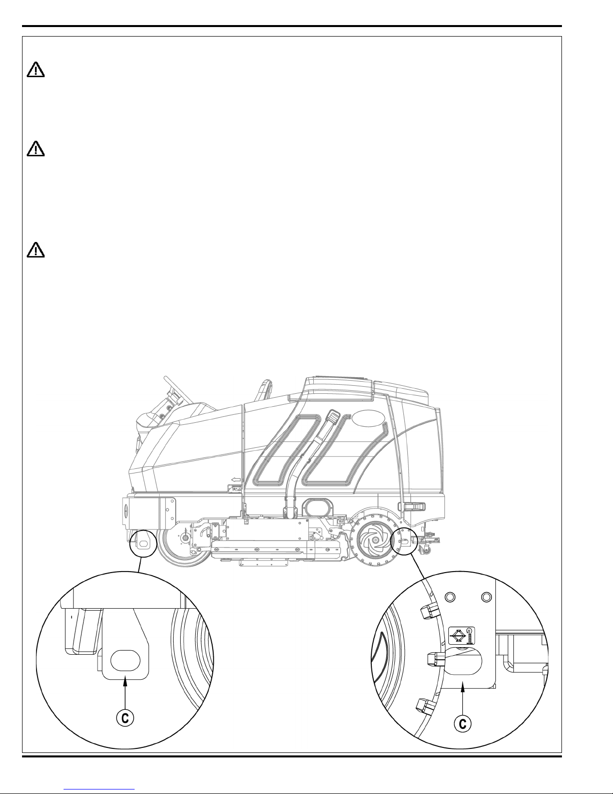
JACKING THE MACHINE
CAUTION!
Never work under a machine without safety stands or blocks to support the machine.
When jacking the machine, do so at designated locations. See Tie Down/Jacking Locations (C) in Figure 2.
TRANSPORTING THE MACHINE
CAUTION!
Before transporting the machine on an open truck or trailer, make sure that:
All access doors are latched securely.
The machine is tied down securely. See Tie Down/Jacking Locations (C) in Figure 2.
The machine Parking Brake (28) is set.
TOWING OR PUSHING A DISABLED MACHINE
CAUTION!
The machine’s drive propelling pump is manufactured with an adjustable tow valve. This valve prevents damage to the hydraulic
system when the machine is being towed/pushed short distances without the use of the engine.
See Figure 3. The tow valve is controlled by the Tow Valve Lever (34) which is accessed by opening and propping up the Engine Cover (3). Pull
the Tow Valve Lever out to disengage the hydrostatic lock between the motor and pump.
The hydrostatic pump can be damaged if the machine is towed with the valve in the normal working position (Tow Valve Lever pushed IN). Note: If
the tow valve is left in free-wheeling position (Tow Valve Lever pulled OUT) the hydrostatic pump can’t drive the machine FWD or REV. No damage
will result, just reset the valve to the normal working position by pushing the lever IN. Tow or push the machine no faster than a normal walking pace
(2-3 miles per hour) and for short distances only. If the machine is to be moved long distances, the front drive wheel needs to be raised off the fl oor
and placed on a suitable transport dolly.
FIGURE 2
6 - FORM NO. 56043124 - Condor XL
™
Page 7
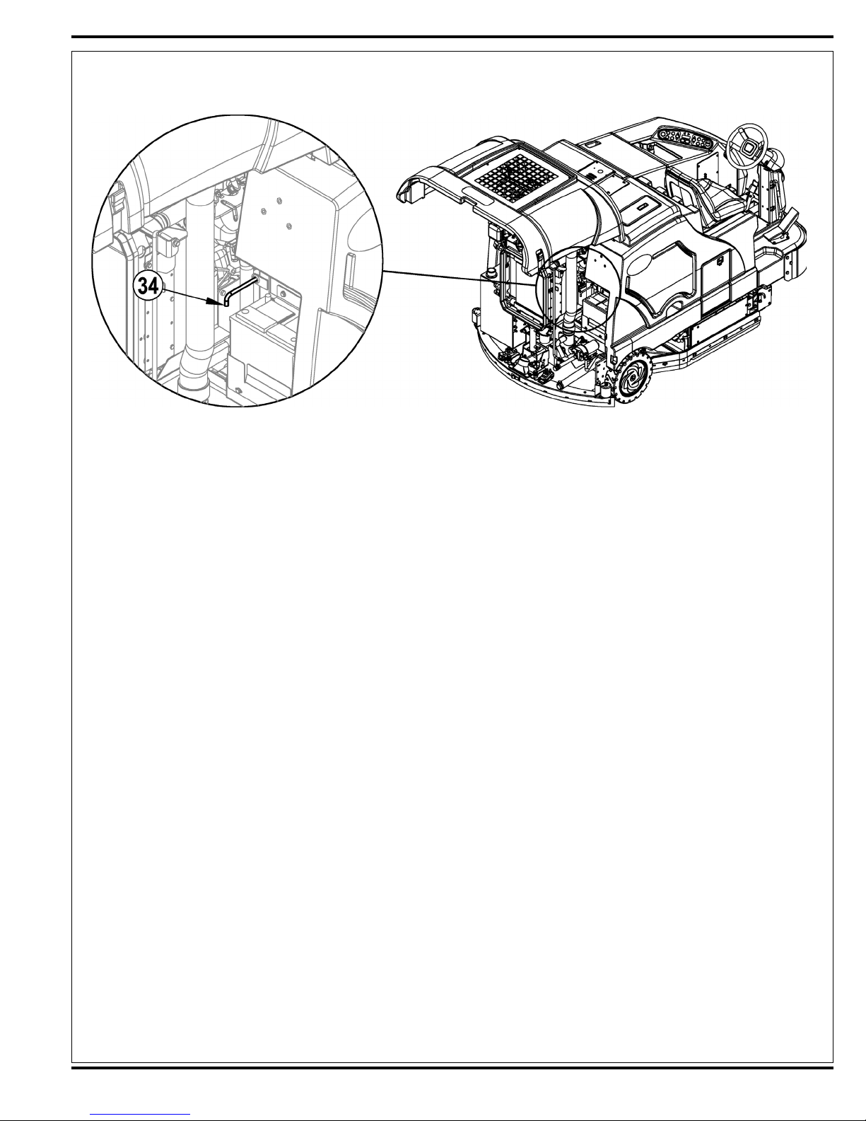
FIGURE 3
OTHER MANUALS AVAILABLE
The manuals listed below can be found via Nilfi sk-Advance’s two electronic supported databases. They are:
Nilfi sk-Advance website (www.advance.us.com) and EzParts service/parts CD-ROM.
Parts List - Form Number .................................... 56042484 (all systems w/optional kits and accessories)
Instructions for Use - For m Number .................. 56041705 (English, Spanish)
Engine Manuals
PSI Tier II 1.6L PFI Certifi ed Engine Service Manual G/LP ......................................................... PSI1P6LPFI-A
Kubota V1505TE Diesel Engine Operator Manual
(English, French, German, Italian, Spanish) ................................................................................ 16622-8916-3
Kubota V1505TE Diesel Engine Service Manual (English, French, German) ............................. 97897-01640
Kubota V1505TE Diesel Engine Service Manual (English) ......................................................... 97897-02432
FORM NO. 56043124 - Condor XL™ - 7
Page 8
DIAGNOSTIC AND SERVICE TOOLS
In addition to a full set of metric and standard tools, the following items are required in order to successfully and quickly perform troubleshooting and
repair of Nilfi sk-Advance Industrial fl oor cleaning equipment.
Laptop computer loaded with current version of EzParts, Adobe Reader and (preferably cellular) internet access
Digital voltmeter (DVM) with DC current clamp
Hydrometer
Battery load tester for checking 6V and 12V batteries
Automotive fuel pressure test gauge (used on gasoline engines)
Static control wrist strap
Set of torque wrenches
Hard (printed) copies of service manuals for regularly serviced machines (available at
sites)
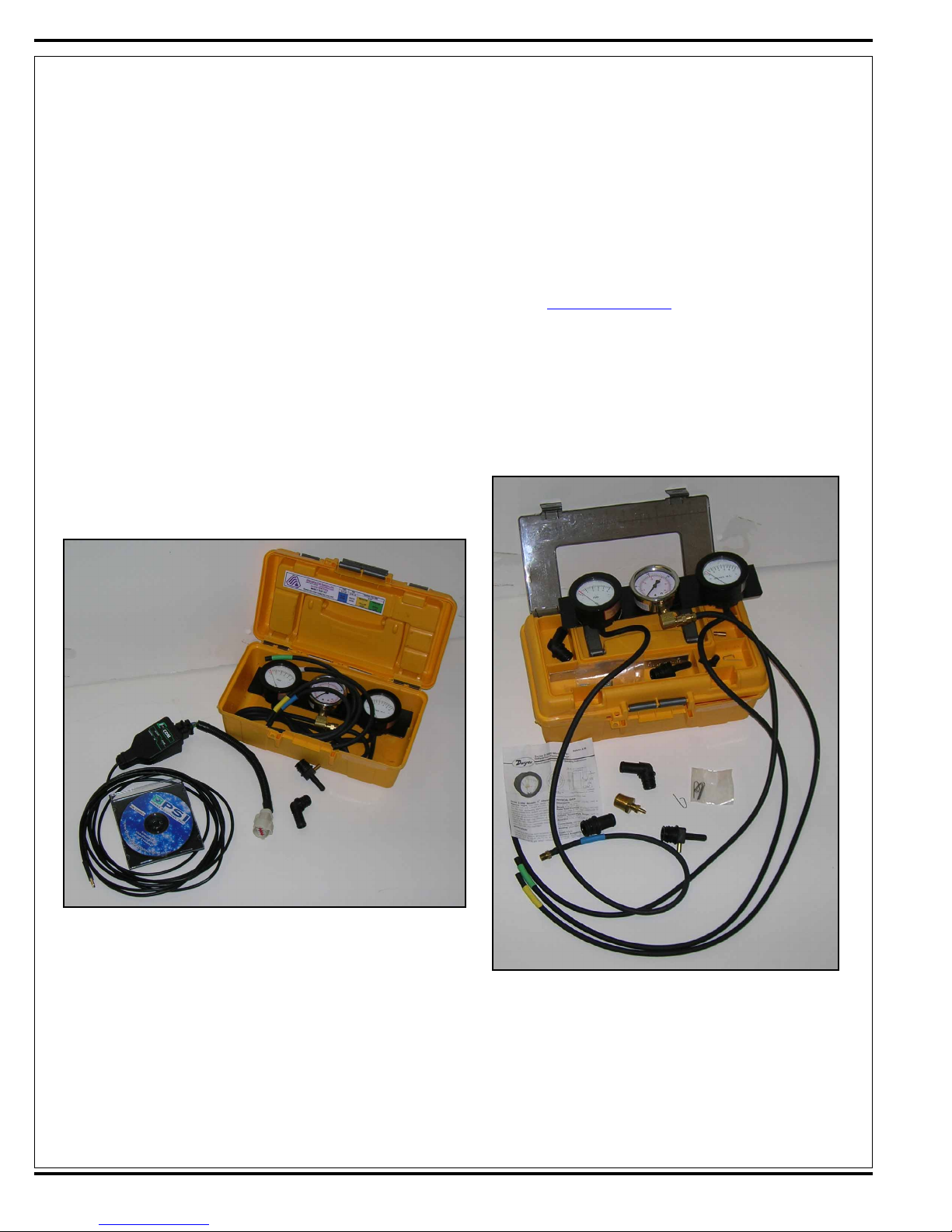
These tools are also available from Nilfi sk-Advance, Inc.:
56407502 Actuator power cord adapter
56205281 Vacuum water lift gauge
www.advance-us.com and other Nilfi sk-Advance web-
56109084 PSI engine service kit (see photo)
8 - FORM NO. 56043124 - Condor XL
™
56504450 PSI LP test kit (see photo)
Page 9
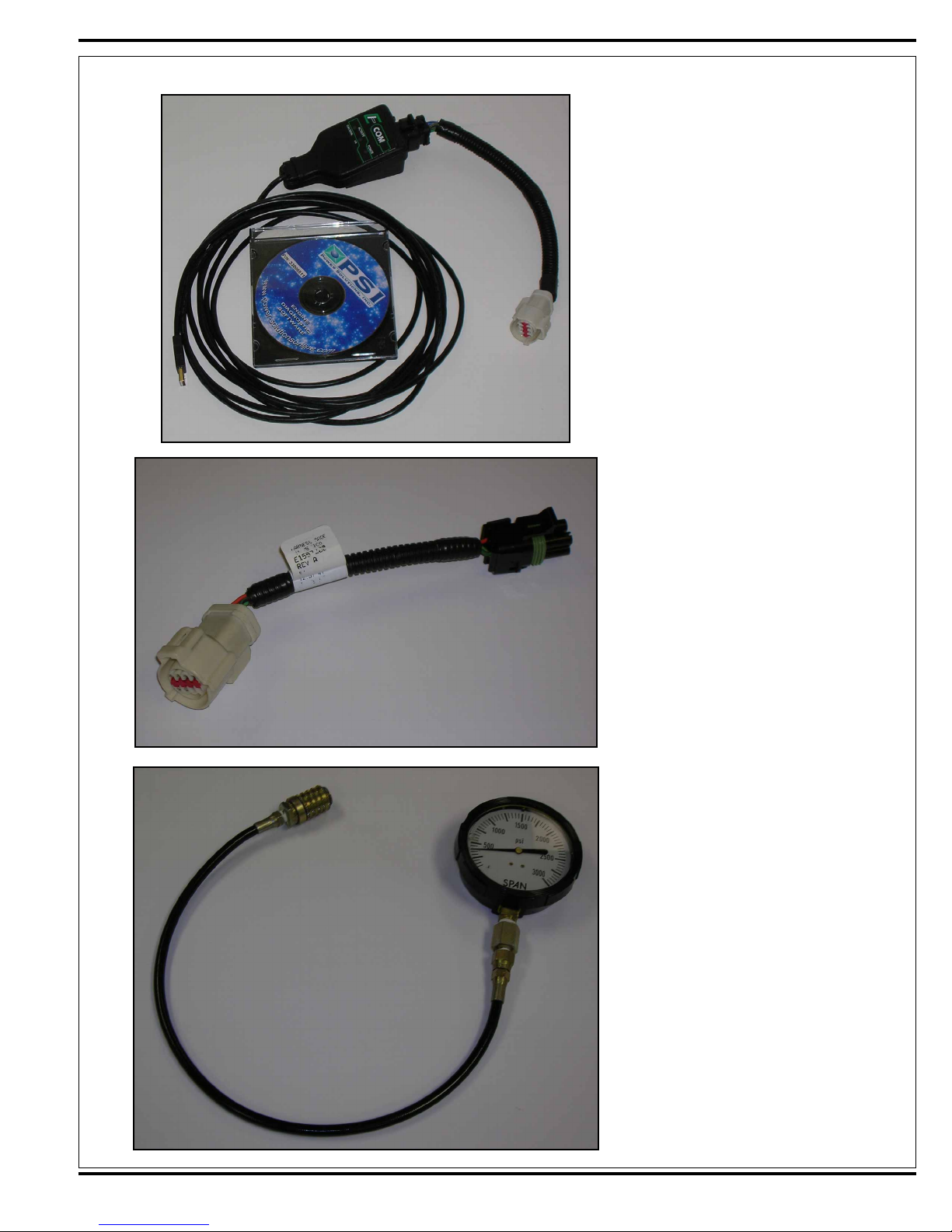
56305647 PSI diagnostic communication
cable and software (see photo)
PSI diagnostics cable, 4-pin – 8-pin
(Gen1 old style) (see photo)
56504516 Hydraulic test gauge w/con-
nector 3000 psi range (see photo)
FORM NO. 56043124 - Condor XL™ - 9
Page 10
TECHNICAL SPECIFICATIONS
General Machine Dimensions and Capacities
Length 100 in (254 cm)
Height 58 in (147 cm)
Height (with overhead guard) 84 in (213 cm)
Width/frame (roller to roller) 56 in (142 cm)
Width (with rear squeegee) 57 in (144.7 cm)
Width (with right side scrub brush) 66 in (167.6 cm)
Cleaning path width (main brush only) 48 in (121.9 cm) deck size all models
Cleaning path width (with right side scrub brush ) 60 in (152.4 cm)
Cleaning path width (dual sweep) 62 in (157.4 cm)
Cleaning path width (left sweep/right scrub) 67 in (170 cm)
Main brush diameter and length 11 in x 48 in (27.9 cm x 121.9 cm)
Side scrub brush (right) 16 in (40.6 cm)
Side broom sweep 20 in (50.8 cm)
Solution tank capacity (3 in from top) 100 gal. (378L)
Recovery tank (shutoff) 100 gal. (378L)
Scrub brush pressure (in lbs) three settings (1) 150 (2) 250 (3) 400
Main brush RPM 400 RPM @2200 engine RPM
3
Debris hopper volume capacity 1.5 ft
Debris hopper weight capacity 150 lbs (68 Kg)
Weight empty 2975 lbs (1349 Kg)
Weight GVWR 4135 lbs (1875 Kg)
Minimum aisle turn 119 in (302 cm)
Transport ground clearance 3 inches (7.62 cm) when in transport
Operator sound level @ operator ear 82.4 dBA @ 2200 RPM
Vibration level @ steering wheel does not exceed .80 m/s
Certifi cation ETL
(.04 m3)
10 - FORM NO. 56043124 - Condor XL
™
Page 11
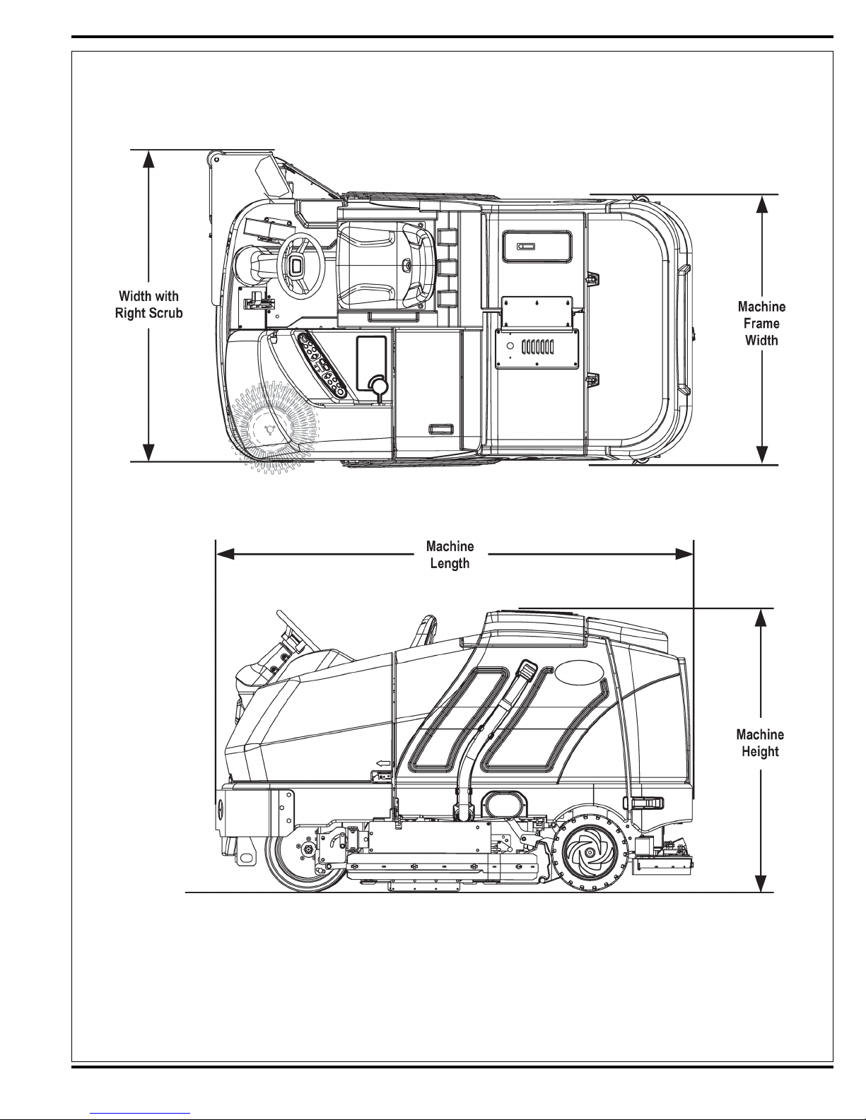
FIGURE 4
FORM NO. 56043124 - Condor XL™ - 11
Page 12
Fastener Torque Specifi cations
Standard Torque Specifi cations (unless otherwise speci-
fi ed)
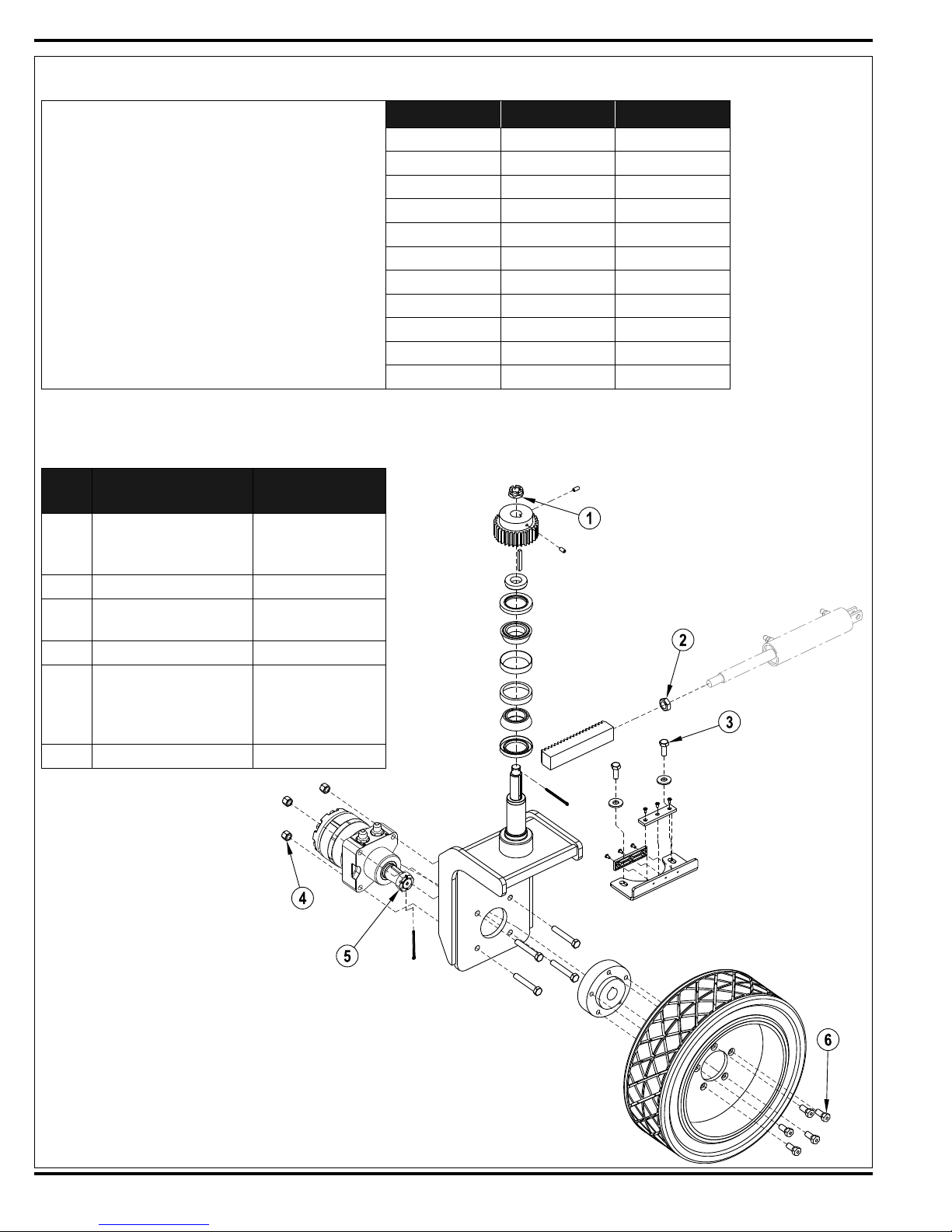
Drive Wheel System Torque Specifi cations
See Figure 5
Size Plated Steel Stainless Steel
#10 42 in.-lb. 28 in.-lb.
1/4“ 100 in.-lb. 67 in.-lb.
5/16” 17 ft.-lb. 11 ft.-lb.
3/8” 31 ft.-lb. 20 ft.-lb.
1/2” 75 ft.-lb. 50 ft.-lb.
3/4” 270 ft.-lb. 180 ft.-lb.
M5 61 in.-lb. 36 in.-lb.
M6 9 ft.-lb. 62 in.-lb.
M8 22 ft.-lb. 13 ft.-lb.
M10 44 ft.-lb. 25 ft.-lb.
M12 70 ft.-lb. 40 ft.-lb.
FIGURE 5
Item
No.
1
2 ¾”-16 Hex Jam Nut Torque to 150 ft.-lb.
3 ½”-20 x 1.25 Hex Screw
4 ½”-13 Nyloc Hex Nut Torque to 100 ft.-lb.
5
6 Wheel Studs Torque to 100 ft.-lb.
Description
Steering Castle (Spindle)
Nut
Drive Wheel Motor
Spindle Nut
Torque
Specifi cation
Torque to 40 ft.-lb.,
then loosen to align
cotter pin.
Use Loctite 242,
torque to 90 ft.-lb.
Torque to 375 ft.-lb.
(lubed) or 475 ft.-lb.
(dry), then tighten to
align cross hole.
12 - FORM NO. 56043124 - Condor XL
™
Page 13
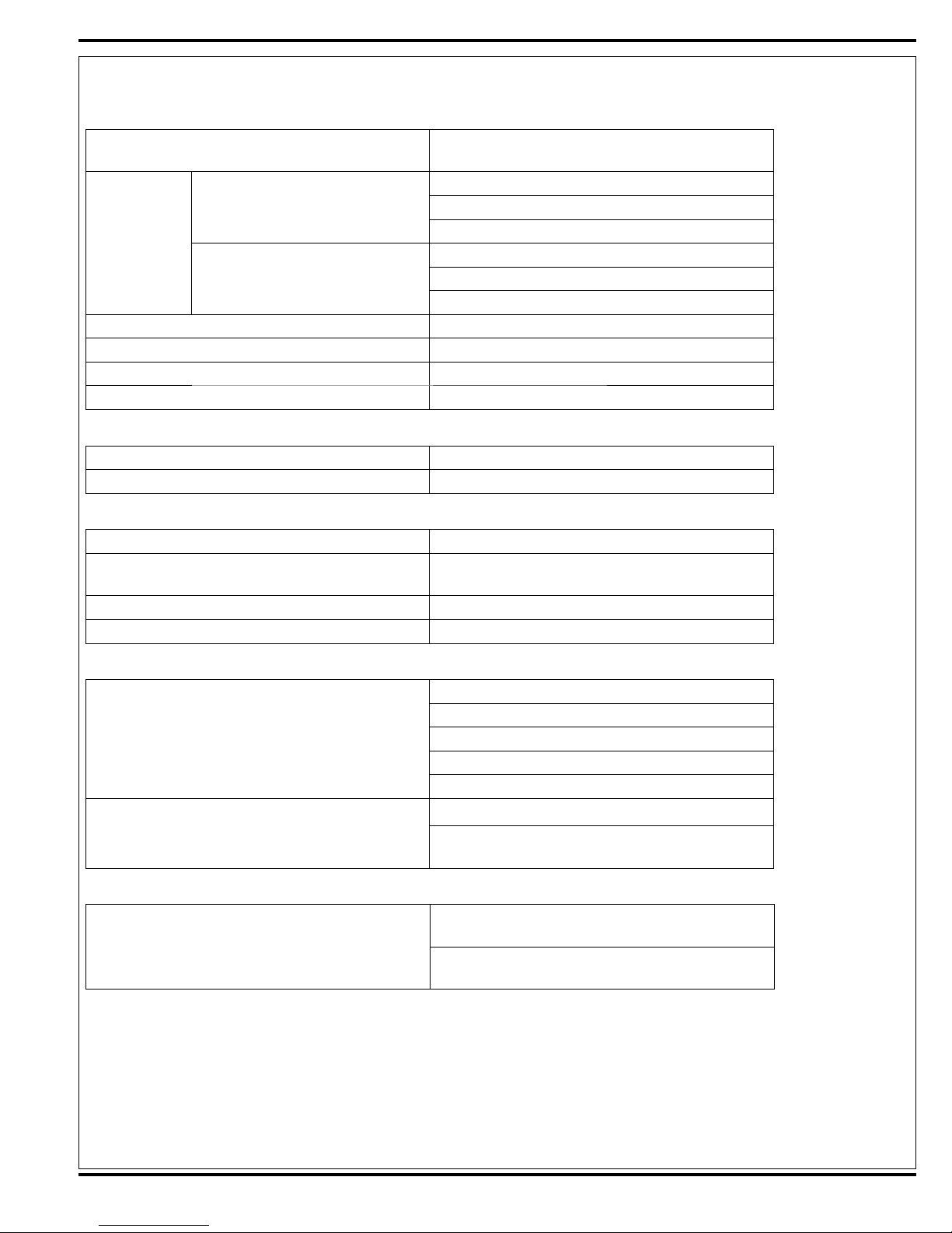
TECHNICAL SPECIFICATIONS
Power System Performance
Engine
4-cylinder 1.6L GM (gasoline and LP)
Engine speeds
4-cylinder 1505 Kubota Diesel
Transport speed forward 8 mph (12.8 kph)
Transport speed reverse 3 mph (4.8 kph)
Grade ability – Cleaning 6° / 10.5% - all models
Grade ability – Transporting 9° / 16% - all models
Hydraulic
Hydraulic reservoir 10 gal. (37.8 L), fl uid type: 10W-30 engine oil
Hydraulic system components See hydraulic manual section
Steering Brakes and Tires
Steering Front wheel, hydraulic cylinder and rotary valve controlled
Brakes (service)
Tire (front 1) drive/steer Size 18 in x 6 in (457 mm x 152 mm) P7 solid
Tire (rear 2) load bearing Size 16 in x 4 in (406 mm x 101 mm) solid
Solution and Chemical System Delivery Rates
Solution system fl ow rates (fi ve settings)
AXP detergent dispensing system
Extended Scrub System
Dust Guard system (side broom dust control )
See the ENGINE SYSTEM/ENGINE SPECIFICATIONS
section
Idle - 1200 RPM
Normal Run - 2200 RPM
High Output Turbo - 2400 RPM
Idle - 1300 RPM
Normal Run - 2200 RPM
High Output Turbo - 2400 RPM
Mechanical drum brakes, one on each rear wheel, cable
actuated
Setting 1 – 1.6 gal/min (6 L/min)
Setting 2 – 1.9 gal/min (7.2 L/min)
Setting 3 – 2.3 gal/min (8.7 L/min)
Setting 4 – 2.7 gal/min (10.2 L/min)
Setting 5 – 3.1 gal/min (11.7L/min)
Refi llable cartridge, Qty (2) 2.5 gal (9.5L)
Available dilution rates: 300:1, 256:1, 200:1, 150:1, 128:1,
100:1, 64:1, 50:1, 32:1, 26:1
Standard nozzle size .015” dia. Flow volume – .033 gal/min
(0.125 L/min) @ 40 psi.
Optional nozzle size .026 Dia. Flow volume – .1 gal/min
(.379 L/min) @ 40 psi.
FORM NO. 56043124 - Condor XL™ - 13
Page 14
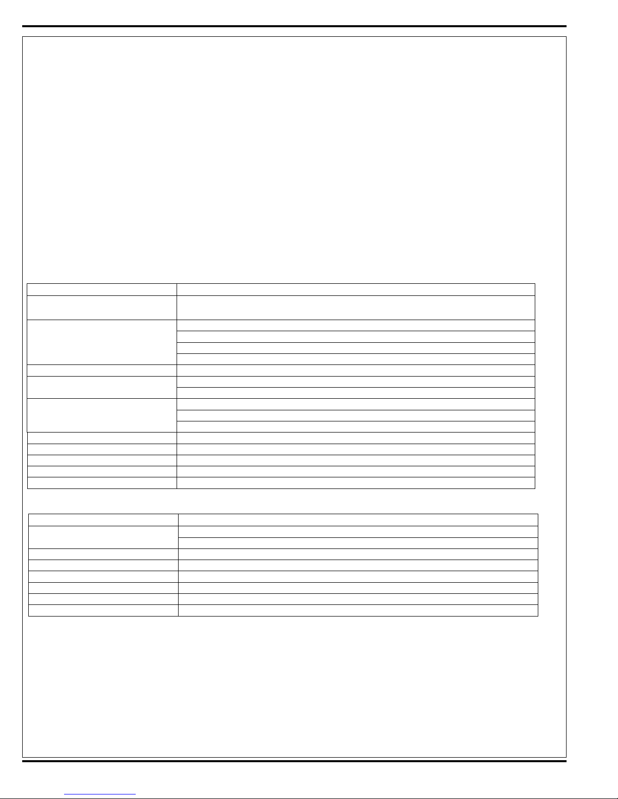
MAINTENANCE
MAINTENANCE SCHEDULE
Keep the machine in top condition by following the maintenance schedule closely. Maintenance intervals given are for average operating
conditions. Machines used in severe environments may require service more often. In general:
• Keep the fuel tank filled (gasoline and diesel). This helps to reduce condensation and moisture entering the fuel system.
• Be aware of the red Warning Indicator Light (62), the yellow Attention Indicator Light (66) and the LCD Display (64) on the operator
panel for icons and fault codes that indicate a critical or non-critical fault condition. Note: Refer to the MAIN CONTROL BOARD
WARNING AND ATTENTION INDICATOR LIGHTS section for a listing and explanation of the LCD display icons and fault codes.
• Reference the engine service manual for recommended engine service intervals and procedures.
Recommended Service Materials
• Engine Oil (5W-30)
• Hydraulic Oil (10W-30)
• Manufacturer-recommended Coolant (antifreeze) 50/50 mix
• Lithium-base Grease
• Loctite
• Never-Seez
Daily Maintenance
Perform “After Use” maintenance steps
Engine
Operator panel Check for a hydraulic filter plugged indicator light (66) on the operator panel display (64)
Hydraulic system
Recovery tank
Squeegee pick up tool Clean the tool, check the blades for damage/wear and deflection
Scrub housing side skirts Check for damage/wear on both the main and right side
Scrub brushes, main and right side scrub Check for debris wrapped around the brushes and for damage/wear
Wet debris hopper Clean the hopper, debris screen and hose
Parking brake and foot pedal brake Check for proper operation of brakes, make adjustments as needed
Maintenance Every 15-20 Hours
Battery
Solution tank filter Inspect and clean the debris filter on the solution filter system
Solution delivery trough Clean the drain holes
AXP detergent system Purge the chemical delivery lines
Scrub deck skid plates Inspect for wear (replace if worn to ǩ inch
Scrub brushes Rotate and flip the main scrub brushes
Dust Guard Clean the dust control system spray nozzles
®
(or equivalent) thread sealant in the appropriate grades
®
(or equivalent) anti-seize compound
Maintenance Item Procedure
“After use” maintenance is normally the responsibility of the machine operator. See “AFTER
USE” maintenance steps in the operator manual.
Check the engine oil level
Check the engine coolant level in the reservoir
Check for engine and coolant leaks
Check the air cleaner service indicator and service the air filter when the indictor is shown red
Check the oil level in the hydraulic oil reservoir (level should be to bottom of screen)
Check for any hydraulic leaks
Check the cover gasket for damage/wear
Check that the drain hose cap is sealed
Drain and clean the inside of the tank, flush with clean water
Maintenance Item Procedure
Check the electrolyte level in the battery
Check the battery cables and connections
14 - FORM NO. 56043124 - Condor XL
™
Page 15
MAINTENANCE
MAINTENANCE SCHEDULE
Maintenance Every Month (see Figure 6)
Maintenance Item Procedure
Squeegee Caster Wheel Axle and
Pivot (A)
Steering Rack (A)
Angle adjustment knob threads on
the squeegee mount (A)
Squeegee tool end wheels (B)
Fuel Tank Cover Latch (B)
Pump a small amount of grease into each grease fi tting on the machine until grease seeps
out around the bearings.
Apply grease to lubricate
Recovery Tank Latch (B)
AXP Cover Latch (B)
Brake Pedal (parking brake) linkage
(B)
Apply light machine oil to lubricate
Maintenance Every 150 Hours
Maintenance Item Procedure
Engine maintenance
Radiator and oil cooler Inspect and clean the exterior core cooling fi ns
Steering Inspect and apply grease to the spur gear and rack
LP fuel system electronic pressure regulator (EPR) – LP engines only
Change the engine oil and oil fi lter. *Also review the engine manufacturer’s additional maintenance
requirements
Inspect and drain any oil buildup from the LP fuel system EPR
Maintenance Every 400 Hours
Maintenance Item Procedure
Air intake housing and hoses
Hydraulic hoses Inspect for leaks, wear
Battery Check electrolyte level; check terminals for corrosion, loose connections
Fuel Filter
Inspect the complete air intake system for correct routing, kinks, restrictions, sound tight connections, holes and cracks in hoses
Replace fuel fi lter cartridge (located before injector pump). Use Nilfi sk-Advance p/n 56419086
Replace the fuel fi lter at the electronic fuel pump
Maintenance Every 800-1000 Hours
Maintenance Item Procedure
Engine maintenance Change the spark plugs
Hydraulic oil reservoir Change the reservoir oil and fi lter
Radiator Flush and refi ll radiator with 50/50 mix of water and anti freeze
Maintenance Every 2000 Hours
Maintenance Item Procedure
Engine maintenance * Review the engine manufacturer’s additional maintenance requirements
Note: The engine maintenance schedule shown lists the recommended engine service intervals. Refer to the OTHER MANUALS AVAILABLE/Engine Manuals section for list of available engine manufacturers’ service manuals. Refer to these manuals for more complete maintenance and service information and instructions.
FORM NO. 56043124 - Condor XL™ - 15
Page 16
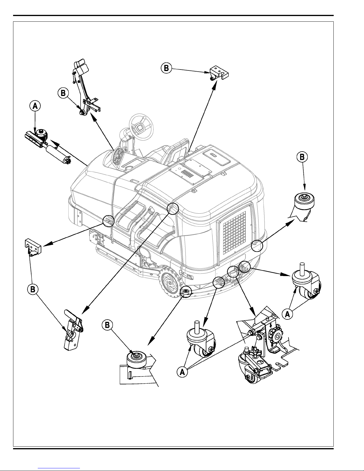
FIGURE 6
16 - FORM NO. 56043124 - Condor XL
™
LUBRICATION
POINTS
Page 17
MAINTENANCE
HYDRAULIC OIL
Open and prop the Engine Cover (3) to access the hydraulic oil reservoir. Remove the Fill Cap (44) from the tank and look to the bottom of the fi ller
screen. If the oil level is below the bottom of the fi ller screen, add 10W-30 motor oil until the bo ttom of the fi ller screen is covered. (The oil level
should not be higher than 1/2” (12.7mm) above the bottom of the fi ller screen.) Change and fl ush the oil if major contamination from a mechanical
failure occurs.
ENGINE MAINTENANCE
ENGINE OIL – GASOLINE / PETROL AND LPG
Check the engine oil level when the machine is parked on a level surface and the engine is cool. Change the engine oil after the fi rst 35 hours
of operation and every 150 hours after that. Use any SF or SG rated oil meeting API specifi cations and suited to seasonal temperatures. Refer
to the engine manufacturers’ service manuals for oil capacities and additional engine specifi cations. Replace the oil fi lter with every oil change.
TEMPERATURE RANGE OIL WEIGHT
Above 60° F (15° C) SAE 10W-30
Below 60° F (15° C) SAE 5W-30
ENGINE OIL – DIESEL
Check the engine oil level when the machine is parked on a level surface and the engine is cool. Change the engine oil after the fi rst 35 hours of
operation and every 150 hours after that. Use CF, CF-4 or CG-4 oil meeting API specifi cations and suited temperatures.
*Important: Reference the oil/fuel type note below for further diesel oil recommendations. Refer to the engine manufacturers’ service manuals for
oil capacities and additional engine specifi cations. Replace the oil fi lter with every oil change.
TEMPERATURE RANGE OIL WEIGHT
Above 77 °F (25 °C) SAE 30 or 10W-30
32 °F to 77 °F (0 °C to 25 °C) SAE 20 or 10W-30
Below 32 °F (0 °C) SAE 10W or 10W-30
* Diesel Lubricating Oil Note:
With the emission control now in effect, the CF-4 and CG-4 lubricating oils have been developed for use with a low-sulfur fuel used in on-road vehicle
engines. When an off-road vehicle engine runs on a high-sulfur fuel, it is advisable to employ the CF, CD or CE lubricating oil with a high total
base number. If the CF-4 or CG-4 lubricating oil is used with a high-sulfur fuel, change the lubricating oil at shorter intervals.
Recommended lubricating oil when low-sulfur or high-sulfur fuel is employed
Fuel
Lubricating
Oil class
CF
CF-4
CG-4
O : Recommended X : Not recommended
Low sulfur
(0.5 % ≥)
OO
OX
OX
High sulfur Remarks
TBN ≥ 10
SPECIAL LIQUID PROPANE FUEL SYSTEM MAINTENANCE ON THE GM 1.6L ENGINE
Every 150 hours inspect and drain any oil buildup from the LP fuel system electronic pressure regulator (EPR). During the course of normal operation, oils or “heavy ends” may build inside the chambers of the propane regulator. These oils and heavy ends may be a result of poor fuel quality,
contamination of the fuel supply chain, or regional variation in the makeup of the fuel. If the oil buildup is signifi cant it can affect the function of the
fuel control system. Note: Reference the Tier 2 PSI 1.6l PFI certifi ed engine service manual, form # PSI1P6LPFI-A, and follow the procedure to
drain the EPR regulator.
FORM NO. 56043124 - Condor XL™ - 17
Page 18
MAINTENANCE
ENGINE COOLANT
CAUTION!
Do not remove the radiator cap when the engine is hot.
To check the engine coolant level, open and prop the Engine Cover (3) and observe the coolant level in the Coolant Overfl ow Tank (6). If the level is
low, add a 50/50 mix of water and the recommended type antifreeze. Clean the radiator and oil cooler exteriors by washing with low-pressure water
or using compressed air every 150 hours. Service Note: The oil cooler tips out for easy cleaning.
ENGINE AIR FILTER MAINTENANCE
Check the Engine Air Filter Service Indicator (5) before each use of the machine. Do not service the air fi lter unless the red fl ag is visible in the
service indicator.
CAUTION!
When servicing the engine air fi lter elements, use extreme care to prevent loose dust from entering the engine. Dust can severely
damage the engine.
The engine air fi lter contains a Primary (outer) and a Safety (inner) fi lter element. The Primary Element can be cleaned twice before being replaced.
The Safety Element should be replaced every third time that the Primary Filter Element is replaced. Never attempt to clean the Inner Safety Element.
To clean the Primary Filter Element, unsnap the two clips at the end of the air fi lter and remove the end housing. Pull the primary element out. Clean
the element with compressed air (maximum pressure 100 psi) or wash it with water (maximum pressure 40 psi). DO NOT put the element back into
the canister until it is completely dry.
18 - FORM NO. 56043124 - Condor XL
™
Page 19
MAINTENANCE
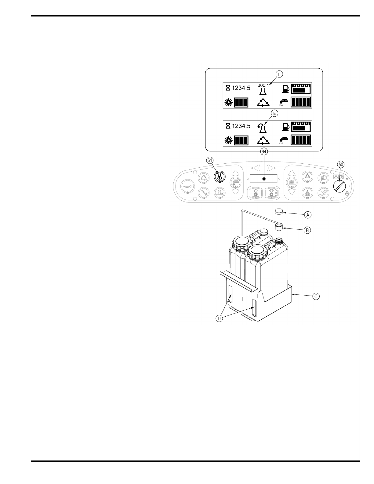
AXP SYSTEM
You will need to purge the system of the previous detergent when switching to a different detergent. SERVICE NOTE: Move machine over fl oor
drain before purging because a small amount of detergent will be dispensed in the process.
To Purge When Changing Chemicals (the scrub system
must be off):
1 Disconnect and remove the detergent cartridge.
2 Turn the key switch (50) on and wait a few seconds for
the start-up sequence to fi nish.
3 Press and hold the detergent switch (61) for approxi-
mately two seconds.
4 Release the switch when the chemical purge icon (E) ap-
pears on the display and the indicator on the detergent
switch (61) starts fl ashing.
Note: Once activated, the purge process takes at least 10
seconds. See the illustration on this page for Detergent
System indicators. Normally one purge cycle is adequate to
purge the system.
To Purge Weekly (the scrub system must be off):
1 Disconnect and remove the detergent cartridge.
2 Install and connect a Cartridge fi lled with clean hot water.
3 Turn the key switch (50) on and wait a few seconds for
the start-up sequence to fi nish.
4 Press and hold the detergent switch (61) for approxi-
mately two seconds.
5 Release the switch when the chemical purge icon (E) ap-
pears on the display and the indicator on the detergent
switch (61) starts fl ashing.
Note: Once activated, the purge process takes at least 10
seconds. See the illustration on this page for Detergent
System indicators. Normally one purge cycle is adequate to
purge the system.
Note: The Detergent Box (C) has Detergent Level Viewing
Slots (D) for referencing the amount of detergent remaining
in the cartridge(s). When the detergent level is nearing the
bottom of this slot, refi ll or replace the cartridge(s).
To Change the Detergent Mix Ratio (the scrub system
must be on):
1 Press and hold the detergent switch (61) for two seconds.
2 Release the switch once the detergent switch light begins fl ashing.
3 While the light is fl ashing, press and release the detergent switch to select the next detergent mixture ratio. Once the desired ratio is selected,
the detergent system will return to normal operation within three seconds.
Note: The detergent mixture (F) will be displayed for approximately 10 seconds each time the scrub mode changes, or each time the detergent
switch is pressed. Once set, the detergent fl ow rate automatically increases and decreases with the solution fl ow rate, but the detergent mix ratio
will remain the same. If an operator would prefer the fl exibility of setting different detergent dilutions ratios for different solution
specifi c programming option can be found in the Appendix.
Note: During scrubbing, the detergent system can be turned off at any time by pressing the Detergent ON/OFF Switch (61) to allow scrubbing with
water only. No detergent is dispensed until the scrub system is activated and the Drive Pedal (29) is pushed forward.
Service Note: Follow the “To Purge Weekly” instructions above if the machine is going to be stored for an extended period of time, or if you plan
to discontinue use of the detergent (AXP) system.
fl ow rates, this
FORM NO. 56043124 - Condor XL™ - 19
Page 20
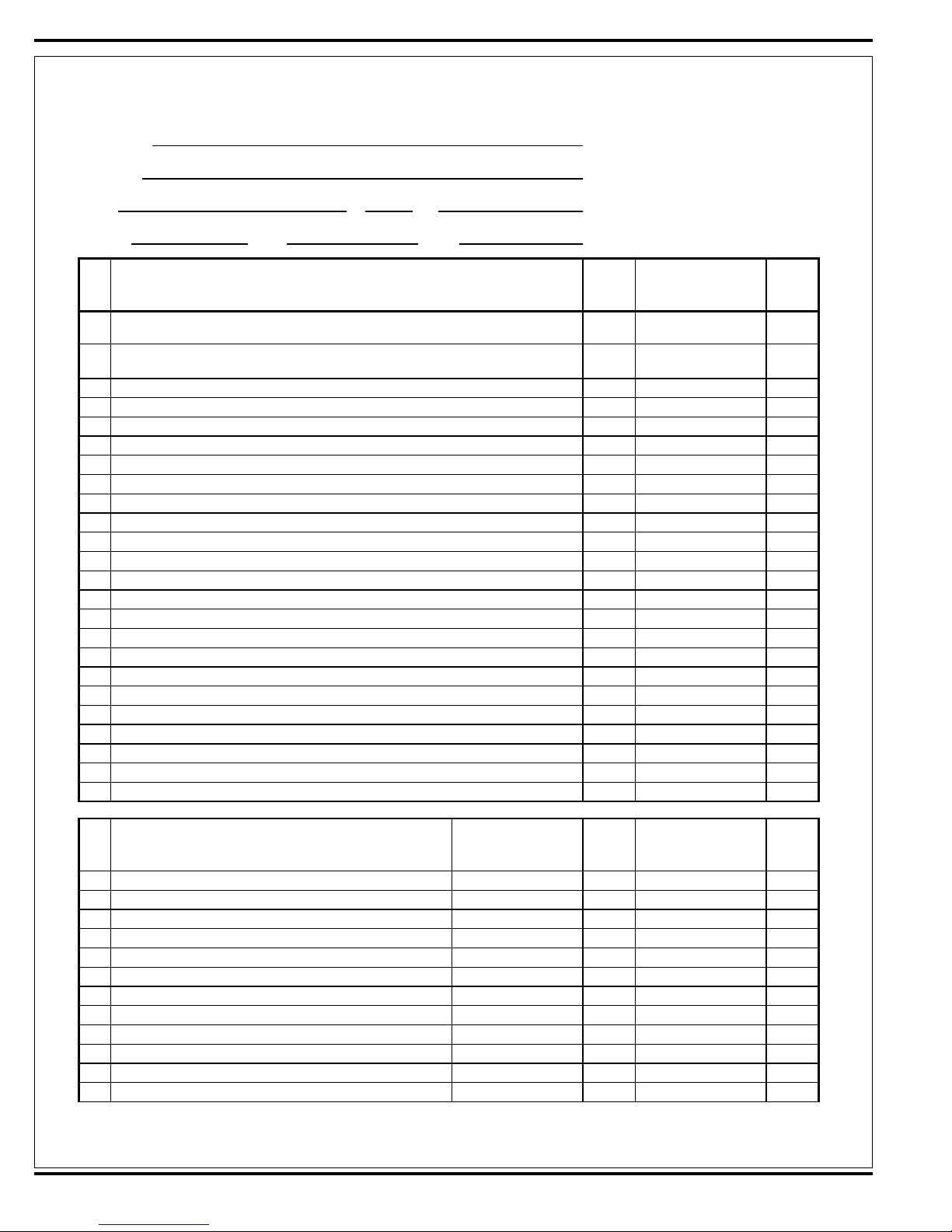
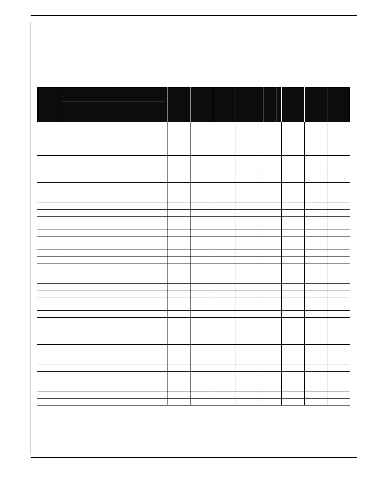
Advance Condor XL 48/60/62/67 G/P/D
PM Checklist
Defect Codes
Customer A needs adjustment
B binding
Address C dirty or contaminated
D damaged, bent or torn
City St Zip L leaks
M missing
Model Serial Hours W worn out
Ref
1 Check drive pedal sensor operation (to test depress drive pedal and start the engine, it
should not start.)
2 Engine starting with pedal in neutral (if it will not start check pedal calibration
programming)
3 Engine idle speed, GM/1200 RPM & Kubota/1300 RPM A rough
4 Normal operational speed (run switch setting) 2200 RPM A low power
Turbo high speed (hold 2200 RPM switch setting for 2 sec. to enter ) 2400 RPM
5 Drive pedal linkage (check for FWD/REV drive and any neutral creep) A B
6 Drive system performance (max Fwd 8 mph) Noisy sluggish
7 Brakes (check both service & parking)
8 Steering excessive play
9 Right side scrub brush raise/lower (model option if equipped) B D L
10 Right side scrub brush on/off (must have main scrub turned on) B L
11 Side sweep broom(s) raise/lower (model option if equipped) A B
12 Side broom(s) on/off B L
13 Dust guard (sweep dust control) On/Off (model option if equipped)
14 Scrub system (Raise/Lower and auto scrubbing functions) <----->
15 Main scrub brushes On/Off (will drift) <----->
16 Scrub Brush (pressure settings 1,2 &3) A B
17 Solution control (On/Off and flow volume min/max) C D
18 Test & purge the detergent AXP system (model option if equipped)
19 Squeegee system (raise/lower and auto lift in reverse) <----->
20 Vacuum Performance (Sealed water lift 34" @ 2200 RPM) C L
21 Headlights, gauges and (optional) accessories rotating beacon, backup alarm <----->
22 Tilt steering mechanism and seat adjustment lever <----->
23
Ref
24 Side sweep broom(s) bristles min wear 3 inches A B D W
25 Side broom motor(s) B L
26 Scrub brush motor(s) Also RT scrub brush B L
27 Main scrub brushes, check for wear and rotate (1.75” length) Min wear .875 D W
28 Scrub deck housing & door skirts
29 Solution system pumps and solenoid valves as many as 4 pumps
30 Solution tank, delivery hoses & filter clean filter screen
31 Vacuum impellor motor & hose C L D
32 Recovery tank screen & float clean screen
33 Recovery tank cover gasket
34 Recovery tank drain hose & cap C D L M
35 Squeegee pick-up hose back flush C L
OPERATIONAL INSPECTION ITEMS
VISUAL INSPECTION ITEMS
Comments
OK
A B C
A
A B W
A C L
C L W
OK
C D W
C L W
C L M
D L W
Defect Codes
(circle)
Defect Codes
(circle)
B C
Does
Not
Work
Does
Not
Work
Copyright 2009 Nilfisk-Advance Page 1 of 2 6/29/2009
20 - FORM NO. 56043124 - Condor XL
™
Page 21
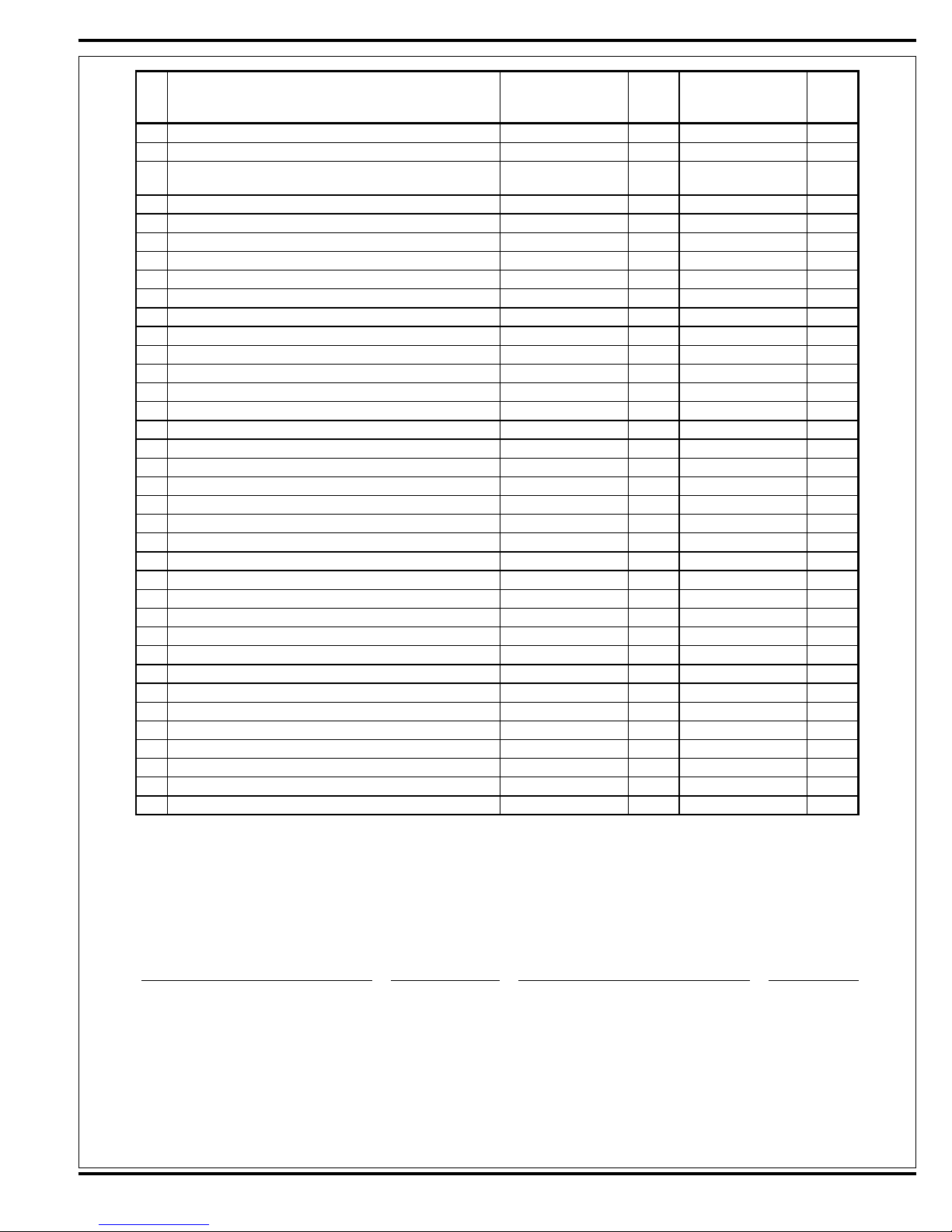
Ref
36 Squeegee tool & blades clean & rotate
37 Squeegee casters, leveler adjustment knob & linkage grease C W
38 Hydraulic lift cylinders (squeegee, RT side & main scrub
39 Battery clean & water C
40 Engine, oil level, hoses & belts C D L
41 Engine air cleaner element (inner & outer) check SVR indicator C L
42 Engine coolant level fill at reservoir C L
43 Radiator & oil cooler core blockage clean
44 Hydraulic oil reservoir level (10W-30 engine oil only) to bottom of screen C L
45 Hydraulic system hoses & fittings L
46 Propulsion (drive) pump dump valve (tow valve) B D
47 Propulsion drive & accessory pump L
48 Propulsion pump hydro back cable & clevis connections A B D
49 Propulsion pump hydraulic filter C L
50 Gasoline/Diesel fuel tank , filter & lines Xx hours
51 LP tank, hoses & fittings L W
52 LP fuel filter SVR life 1500 Hrs C
53 LP fuel regulator, lock off valve & hoses L
54 Diesel glow plug function light hard starting <----->
55 Gasoline & Diesel fuel tank strainer yearly C
56 Brake cable and parking brake pedal A B
57 Circuit breaker panel
58 Front tire (check lug nut torque 100 FT LB, 135Nm)
59 Front drive wheel motor, steer spindle, rack & cylinder grease pinion & rack
60 Front & rear tires tread wear C W
61 Scrub housing debris hopper (tray) clean C
62 Scrub housing recovery hose & pick-up screen back flush/clean C
63 Dust guard spray nozzles & strainers clean C L W
64
65
66
67
68
69
70
71
VISUAL INSPECTION ITEMS (continued)
deck)
Comments
B L
OK
Defect Codes
(circle)
C D W
C D L
C L W
D M W
A
D L W
Does
Not
Work
NOTE: For additional service information see service manual form number 56043124 and
operators manual form number 56041705.
Defect Codes A needs adjustment C dirty or contaminated M missing
B binding D damaged, bent or torn W worn out
L leaks
WORK COMPLETED BY: ACKNOWLEDGED BY:
Service Technician Signature Date Customer Signature Date
Copyright 2009 Nilfisk-Advance Page 2 of 2 6/29/2009
FORM NO. 56043124 - Condor XL™ - 21
Page 22
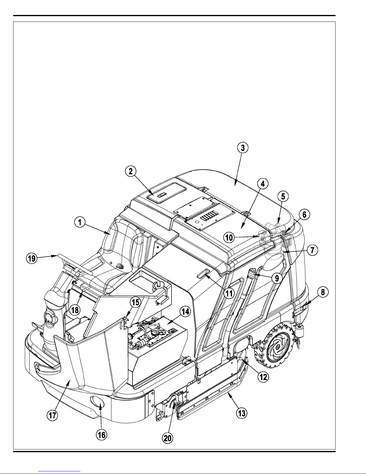
KNOW YOUR MACHINE
As you read this manual you will occasionally run across a bold number in parentheses; for example: (2). These numbers refer to items on the next
four pages. Refer to these pages whenever necessary to locate an item mentioned in the text.
1 Operator’s Seat
2 Solution Tank Fill Cover
3 Engine Cover
4 Recovery Tank Cover
5 Engine Air Filter Service Indicator
6 Coolant Overfl ow Tank
7 Engine Air Filter
8 Engine Cover Latch
9 Recovery Tank Drain Hose
10 Recovery Tank Tilt Out Latch
11 Recovery Tank Tilt Out Grip
12 Left Side Skirt Latch
13 Left Side Skirt
14 Fuel Tank (petrol tank shown)
15 Fuel Tank Cover Latch
16 Headlight
17 Fuel Tank Cover
18 Operator Seat Adjustment Lever
19 Steering Wheel
20 Double Scrub Skirt Holder
22 - FORM NO. 56043124 - Condor XL
™
Page 23
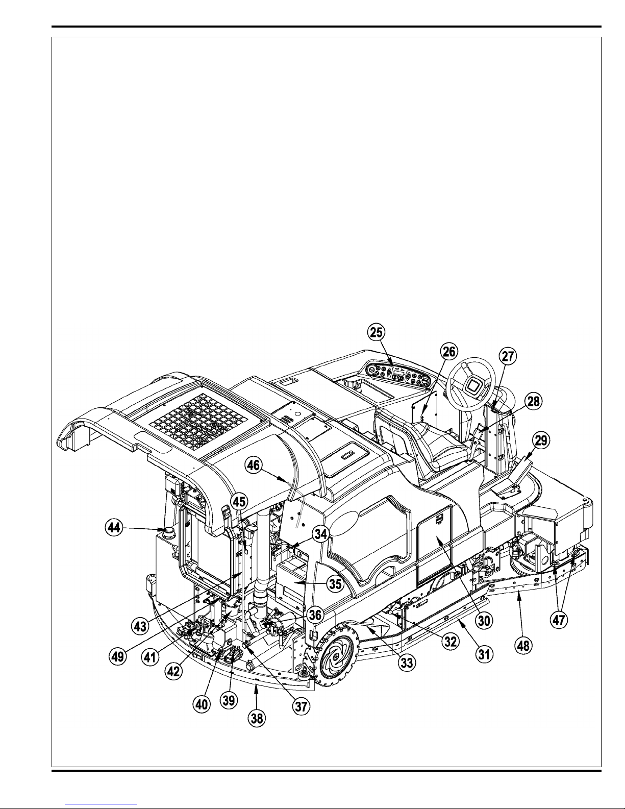
KNOW YOUR MACHINE (CONTINUED)
25 Control Panel
26 Circuit Breaker Panel (see Troubleshooting)
27 Steering Wheel Tilt Adjust Lever
28 Brake Pedal / Parking Brake
29 Drive Pedal, Directional/Speed
30 AXP Cartridge Compartment
31 Right Side Skirt
32 Right Side Skirt Latch
33 Hopper
34 Tow Valve Lever
35 Battery
36 Solution Filter
37 Solution Tank Drain Hose
38 Squeegee Assembly
39 Squeegee Height Adjust Knob
40 Squeegee Mount Wrench
41 Squeegee Tilt Adjust Knob
42 Engine Oil Filter
43 Engine Cover Prop Rod
44 Hydraulic Oil Reservoir Filler Cap
45 Oil Cooler Tilt Out Latch
46 Engine Oil Dipstick
47 Right Scrub Skirt Retainer Knobs
48 Right Scrub Skirt Assembly
49 Engine Oil Drain (under radiator)
FORM NO. 56043124 - Condor XL™ - 23
Page 24
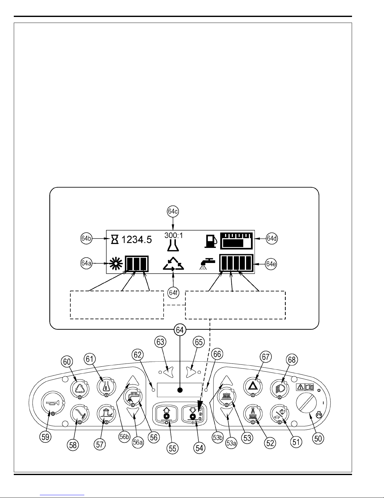
KNOW YOUR MACHINE
CONTROL PANEL
50 Key Switch
51 Engine Speed Switch
52 Dust Guard
53 Side Broom/Scrub ON / OFF Switch
53a Side Broom DOWN adjust Switch
53b Side Broom UP adjust Switch
54 Scrub ON / Scrub Mode Select
55 Scrub OFF
56 Solution Switch
56a Solution Flow Decrease Switch
56b Solution Flow Increase Switch
57 Vacuum Switch
58 Wand Switch (optional)
59 Horn Switch
60 Extended Scrub Switch (optional)
61 Detergent System (AXP models only)
62 Warning Indicator Light (RED) (see page 25)
63 Left Turn Signal (optional)
64 Display
64a Scrub Pressure Indicator
64b Hour Meter
64c AXP Indicator (optional)
64d Fuel Gauge
64e Solution Flow Indicator
64f Extended Scrub Indicator (optional)
65 Right Turn Signal (optional)
66 Attention Indicator Light (YELLOW) (see page 26)
67 Emergency Flashers (optional)
68 Headlights
(scrub 1) (scrub 2) (scrub 3)
press 1 time press 2 times press 3 times
Flow Flow Flow
Rate 1 Rate 2 Rate 3
(scrub 1) (scrub 2) (scrub 3)
press 1 time press 2 times press 3 times
24 - FORM NO. 56043124 - Condor XL
™
Page 25
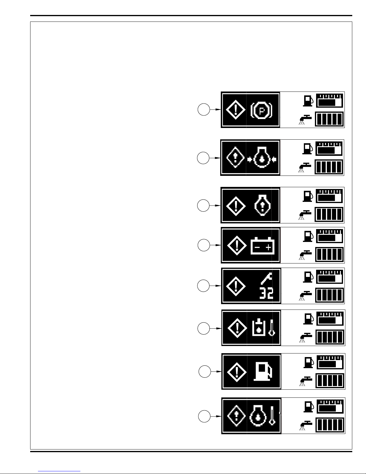
MAIN CONTROL BOARD WARNING AND ATTENTION INDICATOR LIGHTS
The main control board uses a red warning indicator light (62) and a yellow warning indicator light (66) and special dash panel icons to communicate
specifi c monitored operational (modes) activities to the machine operator. When an operational activity or electrical circuit operational problem is
sensed, the red warning and/or yellow attention lights and appropriate icon are displayed. See short explanation for each icon for the two light
groups below.
Red Warning Indicator Light (62)
62A - Parking brake icon;
Displayed icon shows the operator that the parking brake is set. Operator
needs to release the brake pedal, then the icon and light will disappear.
62B - Diesel oil pressure icon;
Active when low engine oil pressure in the diesel engine is sensed.
Check for possible causes for low oil pressure such as engine crankcase
level is low, improper oil viscosity, fault in oil pressure switch S28, excessive engine wear or defective internal oil pump (relief valve). Note: This
icon display is for the Kubota diesel engine only. The GM 1.6L has a
low oil pressure monitor that is activated through the 62C engine service
display icon.
62C - Engine service icon;
Sets when the GM 1.6L engines ECM (electronic control module) activates an engine fault code. See the ENGINE SYSTEM/ENGINE DIAGNOSTICS section for more detailed diagnostic help.
62a
62b
62c
62D - Battery low icon;
Indicates low battery voltage. Check alternator output, test the battery,
clean and tighten cables.
62E - Controller critical fault icon;
The main control board has sensed a specifi c system component
failure(s) and displays a two-digit number with a wrench icon. See the
controller fault (error) code description table for troubleshooting actions.
Note: Some critical faults will prevent the operation of certain machine
functions.
62F - Hydraulic temperature icon;
Icon sets when the hydraulic oil temperature exceeds an average operating temp greater than 220 degrees F for longer than 15 seconds. Possible causes include low oil level in reservoir, debris blocking airfl ow at the
oil cooler, hydraulic component overloads.
62G Low fuel icon;
Icon sets when the fuel sensors read low fuel levels from the liquid fuel
tank (gasoline /diesel) or low pressure from the LP storage cylinder. Refi ll
the gasoline/diesel tank 10 gal capacity. Replace the 33 lbs liquid capacity LP cylinder.
62H Engine coolant temperature icon;
High coolant temperature sensed causes and engine fault. Check for low
coolant level in radiator, debris blocking airfl ow through the radiator, fan
damage, loose fan belt, leaks, bad engine water pump, engine overload
at high ambient temperature.
62d
62e
62f
62g
62h
FORM NO. 56043124 - Condor XL™ - 25
Page 26
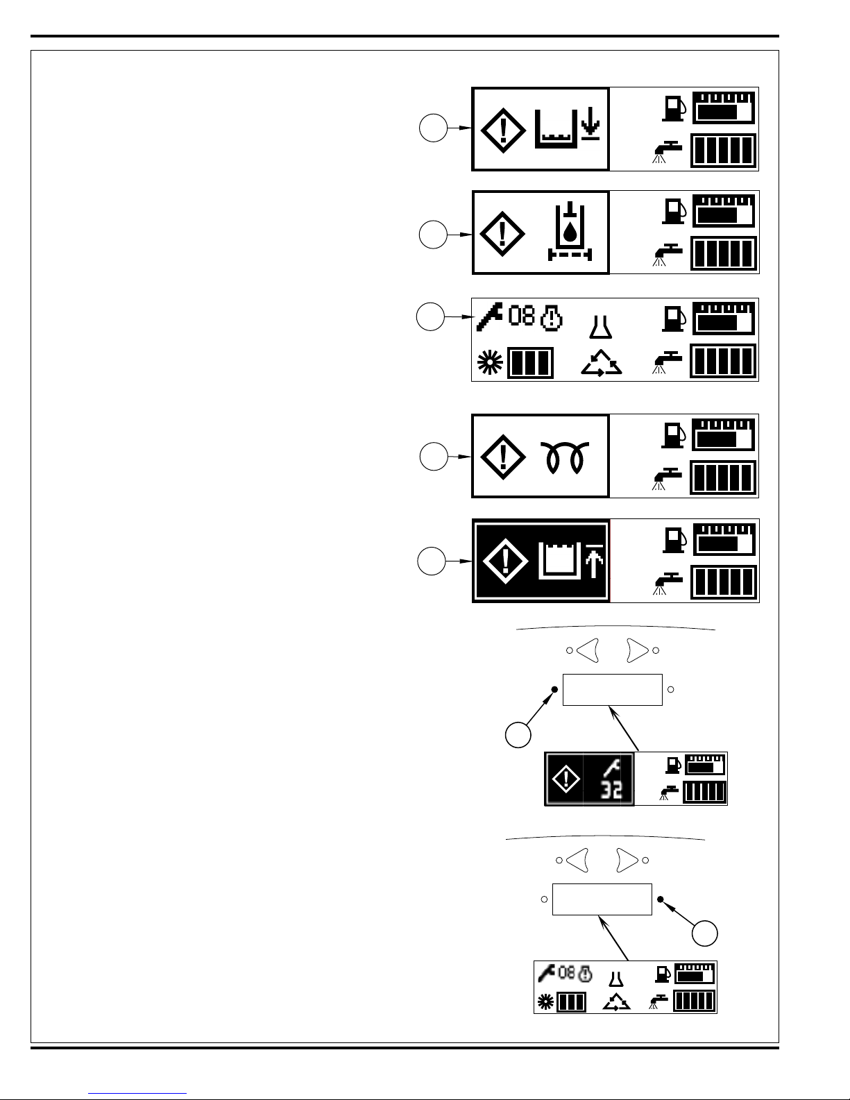
Yellow Attention Indicator Light (66)
66A Solution low icon;
Comes on when the solution level in the tank is low (xx gallons remaining). Fill above the xx gallon level to clear the light and display.
66B Hydraulic fi lter plugged;
Comes on to indicate that the fi lter needs to be replaced (serviced). Note
the oil temperature must be above 100 degrees F for a plugged fi lter to
activate the icon (this prevents a false indication with cold oil start-ups).
66C Controller non critical fault icon;
The main control board has sensed specifi c system component failure(s)
and displays a two-digit number and the wrench symbol. See the controller fault (error) codes description table for troubleshooting actions.
Note: When non-critical faults exist, hour meter will be displayed in rotation with faults.
66D Diesel start glow plug icon;
Comes onto indicates that the key switch is in the run position and the
glow plugs are activated (heating up) for their timed 10 seconds. The
engine can be cranked to start when the yellow attention light and display
icon go out.
66a
66b
66c
66d
300:1
66E Recovery tank full icon;
The tank fl oat has sensed a high water level. The operator needs to
empty the waste water from the tank. If tank is empty and icon is displayed, service (clean) the tank fl oat (could be stuck). Also check the
fl oat circuit wiring for an open.
66e
EXAMPLES:
The main controller board shows the engine service 62C icon with a two-digit
fault code (38) and wrench symbol. This is a critical engine fault code that indicates the main control board received a run-inhibit signal from the ECM (gasoline
and LP) or governor (diesel) that will shut down the engine.
The main controller board shows the non-critical controller fault code 66C icon
with a two-digit code (08) and wrench symbol. This is a non-critical fault code
that indicates the right side scrub solution solenoid valve is over its current limit.
The right side scrub system will shut off but the rest of the machine systems will
continue to operate.
62
66
300:1
26 - FORM NO. 56043124 - Condor XL
™
Page 27
ELECTRICAL SYSTEM
pg y ( )
FAULT CODE SYSTEM DIAGNOSTICS
The following table describes the systems that are disabled for each fault code. This is included to assist the technician in understanding the machine response to a specifi c fault code status.
Note: “X” means the corresponding machine system is disabled (turned off).
Recovery
Display
Code
System
System
Scrub
Solution
System
Chemical
System
Side Scrub
System
Side Sweep
System
Side Mist
System
Recycle
System
Fault Description
00 Solution pump(s) M4 and M6 over current x x x
01 Scrub brush pressure valve solenoids over current
x x x
(L5andL7)
02 Main power relay K1 over current x x x x x x x x
03 Wash hose pump M8 over current
04 Dust guard mist pump M5 over current x
05 No speed input 2200 RPM @ ECM
06 No speed input 2400 RPM @ ECM
07 Main solution solenoid valve L10 over current x x
08 RT side scrub solution solenoid L11 over current x
09 Vacuum fan solenoid L1 over current x x x x
10 Not used
11 Squeegee UP solenoid L3 over current x x x x
12 Squeegee DN solenoid L2 over current x x x x
13 Scrub motor solenoid L4 over current x x x
14 Glow plug relay K4 coil over current
15 Scrub cylinder lock solenoid L6 over current x x x
16 RT side scrub/sweep motor solenoid L8 over
x x
current
17 Back Up alarm over current
18 RT side scrub lift cylinder solenoid L9 over current x
19 Horn over current
20 Left turn signal lamp over current
21 Right turn signal lamp over current
22 Head and tail lamp over current
23 Left stop lamp over current
24 Right stop lamp over current
25 20A circuit breaker CB1 over current
26 20A circuit breaker CB2over current
27 15A circuit breaker CB3 over current
28 20A circuit breaker CB4 over current
29 10A circuit breaker CB5 over current
30 Side sweep lift M7 actuator over current x
31 #1 Chemical pump M10 over current (AXP) x
32 #2 Chemical pump M11 over current (AXP) x
33 Engine hot fault (diesel) x x x x x x x x
34 Hydraulic oil temperature fault
35 Low voltage fault (battery)
36 Service engine fault GM (non critical)
37 Low oil pressure (diesel engine) x x x x x x x x
38 Engine fault (critical) x x x x x x x x
39 Hydraulic filter fault (plugged)
FORM NO. 56043124 - Condor XL™ - 27
Page 28
ELECTRICAL SYSTEM
MAIN CONTROL BOARD FAULT CODES
Fault codes are organized by machine systems (functions). The RED warning light (62) or the Yellow attention light (66) will display on the operators’
control dash panel showing a two-digit number and wrench icon. Listed below is a description and brief comment for each fault code.
Note: C = Critical NC = Non-Critical
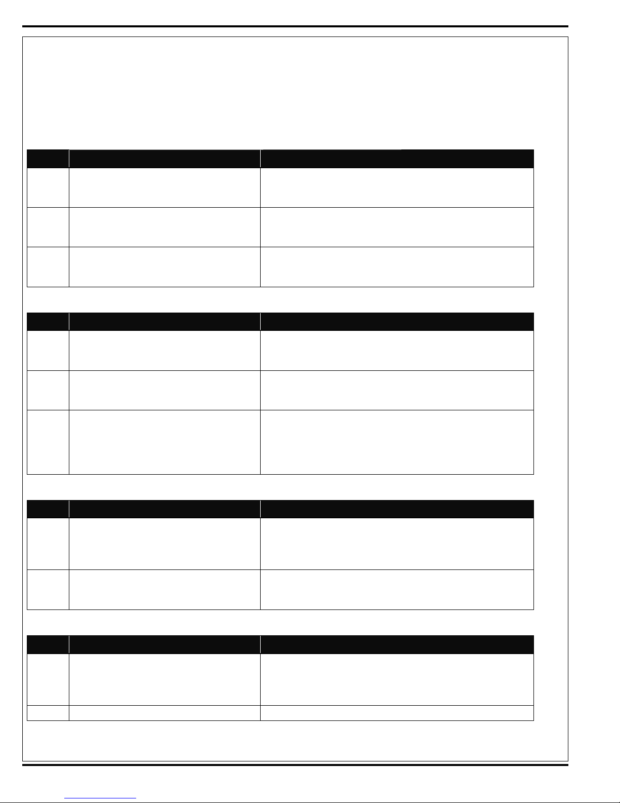
Recovery System
Code# Fault Description by System Family Troubleshooting Actions and Comments
09 C Vacuum fan solenoid over current Check L1 solenoid coil wiring for problems (+ GRN/BRN and - BRN/YEL).
Check coil resistance; less than 6 ohms - replace. Also see vacuum fan
on and squeegee down electrical ladder detail.
11 C Squeegee UP solenoid over current Check L3 solenoid coil wiring for problems (+ GRN/BRN and - BRN/
GRN). Check coil resistance; less than 6 ohms - replace. Also see vacuum fan off and squeegee up electrical ladder detail.
12 C Squeegee DN solenoid over current Check L2 solenoid coil wiring for problems (+ GRN/BRN and - RED/
GRA). Check coil resistance; less than 6 ohms - replace. Also see vacuum fan on and squeegee down electrical ladder detail.
Scrub System
Code# Fault Description by System Family Troubleshooting Actions and Comments
13 C Scrub brush motor solenoid over current Check L4 solenoid coil wiring for problems (+ ORN and - ORN/BLU).
Check coil resistance; less than 6 ohms - replace. Also see main scrub
on and side sweep/RT scrub electrical ladder detail.
15 C Scrub cylinder lock solenoid over current Check L6 solenoid coil wiring for problems (+ ORN and - YEL/BLU).
Check coil resistance; less than 6 ohms - replace. Also see main scrub
on and RT scrub brushes deck pressure electrical ladder detail.
01 C Scrub brush pressure valve solenoids over current Check L5 down and L7 up pressure valve solenoid coils (on same fault
line) for wiring problems, L5 wire colors (+ ORN and - WHT/VIO) and L7
( + ORN and ORN/RED). Check coil resistance; less than 1.8 ohms replace. Also see main scrub on and right scrub brushes deck pressure
electrical ladder detail and further specs.
Solution System
Code# Fault Description by System Family Troubleshooting Actions and Comments
00 C Solution pump(s) over current Check M4 main solution pump and M6 optional recycle pump wiring for
problems (on same fault line), M4 wire colors (+GRN/BRN and - GRN/
BLU) and M6 (+GRN/BRN and - GRA/ORN). Check pump motors for
short circuits replace as needed.
07 NC Main solution solenoid valve over current Check L10 solenoid coil wiring for problems (+ ORN and - YEL/GRN).
Check coil resistance; less than 6 ohms - replace. Also see main scrub
and RT side scrub solution valves and pump electrical ladder detail.
Chemical System AXP
Code# Fault Description by System Family Troubleshooting Actions and Comments
31 NC Chemical pump #1 over current Check #1 chemical pump M10 and #2 chemical pump M11 wiring for
problems, #1 pump wire colors (+RED/WHT and - RED/BLU), #2 (+ BLK/
YEL and - BLK/RED). Check pump motors for short circuit replace as
needed.
32 NC Chemical pump #2 over current See pump #1
28 - FORM NO. 56043124 - Condor XL
™
Page 29
ELECTRICAL SYSTEM
MAIN CONTROL BOARD FAULT CODES
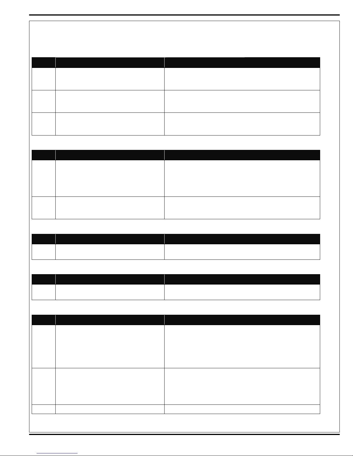
Side Scrub System
Code# Fault Description by System Family Troubleshooting Actions and Comments
18 NC RT Side scrub lift solenoid over current Check L9 solenoid coil wiring for problems (+ ORN and - GRN/VIO).
Check coil resistance; less than 6 ohms - replace. Also see main scrub
and right side scrub lift electrical ladder detail.
16 NC RT side scrub/sweep motor solenoid valve over
current
08 NC RT side scrub solution solenoid valve over current Check L11 solenoid coil wiring for problems (+ ORN and - BLU/YEL).
Side Sweep System
Code# Fault Description by System Family Troubleshooting Actions and Comments
30 Side sweep lift actuator over current Three wires supply power to the M7 side broom lift actuator motor check
16 NC RT side scrub/sweep motor solenoid valve over
current
Side Mist System
Check L8 solenoid coil wiring for problems (+ ORN and - BLK/WHT).
Check coil resistance; less than 6 ohms - replace. Also see main scrub
on and side sweep/right scrub electrical ladder detail.
Check coil resistance; less than 10 ohms - replace. Also see main scrub
and right side scrub solution valves and pump electrical ladder detail.
wiring for problems. Wire colors J3-4 BLU/RED (+) DN otherwise open,
J3-5 WHT/RED (-) UP otherwise open, J3-7 GRA/VIO common wire +
UP and - DN. Test current draw full load 20A +/-2A max. Check for frozen
or binding lift linkage, repair/replace as needed.
Check L8 solenoid coil wiring for problems (+ ORN and - BLK/WHT).
Check coil resistance; less than 6 ohms - replace. Also see main scrub
on and side sweep/right scrub electrical ladder detail.
Code# Fault Description by System Family Troubleshooting Actions and Comments
04 NC Side sweep mist pump over current Check Pump motor M5 wiring for problems (+ BLU and - YEL/BLK). Test
current draw 3.9A full load max. Note: 24V pump operating @ 12V
Recycle System
Code# Fault Description by System Family Troubleshooting Actions and Comments
00 C Extend scrub pump over current Check Pump motor M6 wiring for problems (+ GRN/BLU and - GRA/
ORN). Same fault line used for main solution pump M4 and M6.
Engine Speed System
Code# Fault Description by System Family Troubleshooting Actions and Comments
05 C 2200 RPM no input @ ECM Check for 12V (+) from controller wire J2-29 (GRA/ORN) to battery
ground (-) with the engine speed switch 51 active. Should read 12V if 0V
T.S the throttle wire, then if still OV substitute a good know controller and
dashboard panel. If 12V and no 2200 RPM throttle response test engine
controller out put to specifi c throttle control G/LP/D. See engine wiring
diagram for additional help.
06 NC 2400 RPM no input @ECM Check for 12V (+) from controller wire J2-30 (GRA/BLU) to battery
ground (-) with the engine speed switch 51 active. Should read 12V if 0V
T.S the throttle wire, then if still OV substitute a good know controller and
dashboard panel. If 12V and no 2400 RPM throttle response test engine
controller out put to specifi c throttle control G/LP/D.
10 Not used
FORM NO. 56043124 - Condor XL™ - 29
Page 30
ELECTRICAL SYSTEM
MAIN CONTROL BOARD FAULT CODES
Faults Non-Board
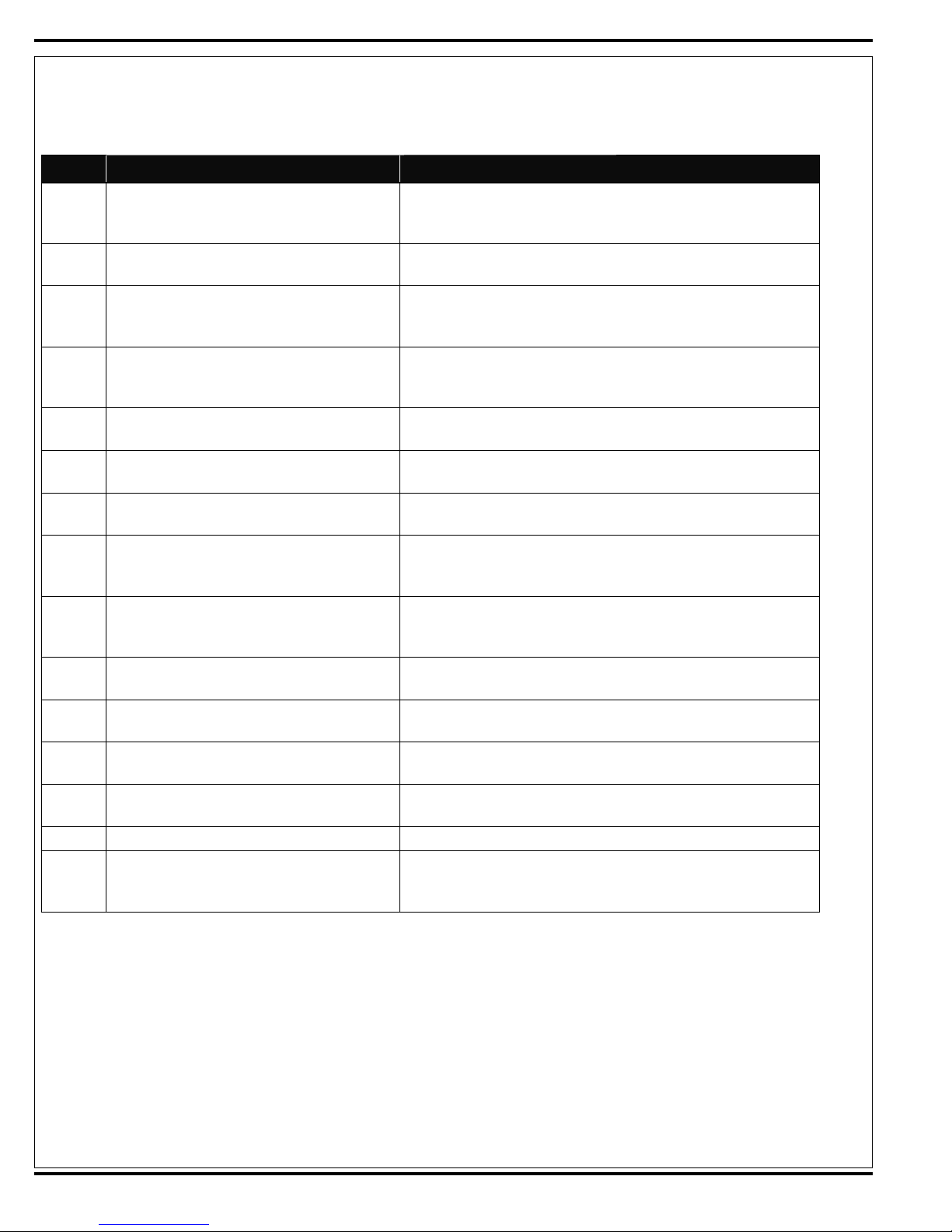
Code# Fault Description by System Family Troubleshooting Actions and Comments
03 NC Wash hose pump over current Check Pump motor M8 wiring for problems (+ BLU and - BLU/RED).
Check pump motor for short circuit (spec XA) replace as needed. Test
current draw 12.5A full load max @12V.
19 NC Horn over current Check H4 horn wiring for problems (+ ORN/GRN and - WHT/YEL). Check
horn for short circuit (spec 4A@12V) replace as needed.
17 NC Back Up Alarm over current Check optional back up alarm wiring for problems (+ ORN/GRN and
- BLU/BLK). Check horn for short circuit (spec .25A at 12V, electronic
alarm) replace as needed.
02 C Main power relay K1 coil over current Check K1 relay coil wiring for problems (+ ORN/GRN and - BLU/GRN).
Check coil resistance; less than 36 ohms - replace. Also see main power
distribution electrical ladder detail. (Spec .29A@12V) replace as needed.
25 C 20A Circuit breaker CB1 over current Control board has sensed open circuit fault for CB1 power for head/tail
and turn signal lamps. Check for GRA/RED wire shorted to ground.
26 C 20A Circuit breaker CB2 over current Control board has sensed open circuit fault for CB2 power for mist pump
(M5) and (M8) wash hose pump. Check for Blue wire shorted to ground.
27 C 15A Circuit breaker CB3 over current Control board has sensed open circuit fault for CB3 power for side broom
actuator motor (M7). Check for Violet wire shorted to ground.
28 C 20A Circuit breaker CB4 over current Control board has sensed open circuit fault for CB4 power for hydrau-
lic solenoid manifold coils (L4-L 11). Check for Orange wire shorted to
ground.
29 C 10A Circuit breaker CB5 over current Control board has sensed open circuit fault for CB5 power for hydraulic
solenoid manifold coils (L1, L2 and L3) also PumpsM4 and M6. Check for
GRN/BRN wire shorted to ground.
20 NC Left turn signal lamp over current Check left turn signal wiring for problems (+ YEL and - BLK). Check lamp
for short (see the I/O table for circuit spec).
21 NC Right turn signal lamp over current Check right turn signal wiring for problems (+ GRN and - BLK). Check
lamp for short (see the I/O table for circuit spec).
22 NC Head and tail lamp over current Check head and tail lamp wiring for problems (+ BRN, YEL/RED, ORN/
BLU and - BLK). Check lamps for short (see the I/O table for circuit spec).
23 NC Left stop lamp over current Check left stop lamp wiring for problems (+ ORN/BRN and - BLK). Check
lamps for short (see the I/O table for circuit spec).
24 NC Right stop lamp over current Same as left stop lamp just different wire color (+ YEL/RED and - BLK).
14 NC Glow plug relay K4 coil over current Check K4 relay coil wiring for problems (+ ORN/GRN and - WHT/ORN).
Check coil resistance; less than 36 ohms - replace. Also see diesel glow
plug starting circuit electrical ladder detail.
30 - FORM NO. 56043124 - Condor XL
™
Page 31

ELECTRICAL SYSTEM
MAIN CONTROL BOARD FAULT CODES
Other Faults Non-board
Code# Fault Description by System Family Troubleshooting Actions and Comments
35 C Low voltage fault (battery) One of the red display panel warning indicator lights see the explanation
for icon 62D
37 C Low oil pressure fault Diesel only - causes engine fault to set. One of the red display panel
warning indicator lights see the explanation for icon 62I
33 C Engine hot fault Coolant temperature high –causes engine fault, sets on diesel machine
only.
38 C Engine fault Occurs if engine temperature too high (diesel), oil pressure low (diesel),
or engine run has change to ignition inhibit and key is on (gas and propane). Note: Engines will shut down. See engine section for the list of
engine codes and process for reading (extracting) codes.
36 NC Service engine fault Gasoline, LP engine (GM 1.6) only, sets when ECM activates MIL output-
could be for mf++-any different reasons. See engine section for the list of
engine codes and process for reading (extracting) codes.
34 C Hydraulic temperature fault Sets when hydraulic oil temperature exceeds 220 F for 15 seconds.
39 NC Hydraulic fi lter fault Sets to warn operator that oil fi lter is plugged and needs to be replaced.
Note: Only activates when oil temperature is above 100 degrees F (this
prevents false signal upon cold engine start up).
FORM NO. 56043124 - Condor XL™ - 31
Page 32

ELECTRICAL SYSTEM
ENGINE ELECTRICAL COMPONENT LOCATIONS – GM 1.6 GASOLINE
O2 Sensor (in exhaust manifold)
(pre CATCON)
TMAP Sensor ETC (Electronic Throttle Control)
ECT (Engine Coolant Temperature)
Sensor
Fuel Pump and Manifold
(mounted on fuel tank)
32 - FORM NO. 56043124 - Condor XL
™
Fuel Injectors and Connectors
ECM and Oil Pressure Switch Crank Position Sensor
Page 33

ELECTRICAL SYSTEM
ENGINE ELECTRICAL COMPONENT LOCATIONS – GM 1.6 LPG
Fuel Temperature Sensor
(mounted on EPR – LPG only)
TMAP Sensor
ETC (Electronic Throttle Control)
O2 Sensor (in exhaust manifold)
ECT (Engine Coolant
Temperature) Sensor
EPR and Fuel Lockout and Filter ECM and Oil Pressure Switch Crank Position Sensor
FORM NO. 56043124 - Condor XL™ - 33
Page 34

ELECTRICAL SYSTEM
ENGINE ELECTRICAL COMPONENT LOCATIONS – KUBOTA DIESEL
Oil Pressure Sensor
(above oil fi lter)
Coolant Temperature Sensor
(above alternator)
34 - FORM NO. 56043124 - Condor XL
™
Governor Engine Speed
Magnetic Pickup
Woodward Governor and
Throttle Actuator
Page 35

ELECTRICAL SYSTEM
ELECTRICAL COMPONENT LOCATIONS
Extended Scrub Pump Extended Scrub Float Switch
Recovery Tank Full Switch
Drive Pedal Sensor
FORM NO. 56043124 - Condor XL™ - 35
Page 36

ELECTRICAL SYSTEM
ELECTRICAL COMPONENT LOCATIONS
Mist Pump (if so equipped) Solution Pump (top) and
36 - FORM NO. 56043124 - Condor XL
™
Wash Pump (bottom)
AXP Pumps
(behind cover panel)
Page 37

ELECTRICAL SYSTEM
CONTROL BOARD ASSEMBLY
J3
J2
Board Relay
Start/Run
Inhibit
K1
Power Relay
J1
FORM NO. 56043124 - Condor XL™ - 37
Page 38

TABLE 1 – CONTROL BOARD CONNECTORS
Note: Also refer to the I/O Tables in the Appendix
Condor XL J1 Main Control Board Connectors
Pin# Wire# Color Type Goes to
J1-1 18-1 GRA input Engine control module output (run signal)
J1-2 20-1 BLK/YEL -CANbus User interface panel (membrane switches)
J1-3 20-1 ORN/BLK +CANbus User interface panel (membrane switches)
J1-4 Open
J1-5 Open
J1-6 Open
J1-7 18-1 GRA/BLK input Fuel level sensor for either petrol/diesel,/LP
J1-8 Open
J1-9 Open
J1-10 18-1 BRN/WHT output Foot pedal position potentiometer (sensor high)
J1-11 18-1 YEL/GRA output Foot pedal position potentiometer (sensor low)
J1-12 18-1 ORN/GRN input Key switch ignition switch (run)
J1-13 Open
J1-14 Open
J1-15 Open
J1-16 18-1 RED/BLK input S29 Horn switch
J1-17 Open
J1-18 16-1 BLK ground Chassis ground X-49
J1-19 18-1 GRN/ORN input Sender hydraulic oil temperature
J1-20 18-1 VIO/WHT input S6 Brake switch
J1-21 18-1 VIO/YEL input S3 Solution empty switch
J1-22 18-1 WHT/BRN output Relay PCB (start inhibit pin #J7-3)
J1-23 Open
J1-24 18-2 VIO/BRN input Ignition switch start position
J1-25 18-1 GRN/YEL input Engine control module (MIL output signal)
J1-26 Open
J1-27 18-1 GRA/YEL input S2 Recovery tank full switch
J1-28 Open
J1-29 Open
J1-30 18-1 VIO/BLU input Engine control module (engine coolant temperature out-
put)
J1-31 18-1 ORN/GRA input Foot pedal position potentiometer (sensor wiper)
J1-32 18-1 RED/YEL input S4 Hydraulic fi lter switch
J1-33 18-1 BRN/BLU input S7 Extend scrub level switch
J1-34 18-1 YEL/WHT output Relay PCB (ignition inhibit pin #J7-7)
J1-35 Open
38 - FORM NO. 56043124 - Condor XL
™
Page 39

Condor XL J2 Main Control Board Connectors
Pin# Wire# Color Type Goes to
J2-1 18-1 BLU/GRN - output K1 power relay coil
J2-2 18-1 BLK/WHT - output S8 side sweep scrub solenoid coil
J2-3 18-1 GRN/VIO - output S9 side scrub lift solenoid coil
J2-4 18-1 YEL/BLU - output S6 scrub cylinder lock solenoid coil
J2-5 18-1 RED/GRA - output S2 squeegee down solenoid coil
J2-6 18-1 BRN/GRN - output S3 squeegee up solenoid coil
J2-7 18-1 ORN/BLU - output S4 scrub brush solenoid coil
J2-8 18-1 BRN/YEL - output S1 vacuum fan solenoid coil
J2-9 Open
J2-10 18-1 BLU/YEL - output L11 solenoid valve, right solution
J2-11 18-1 BLU/BLK - output H3 back-up alarm (optional)
J2-12 16-1 ORN + input CB4 circuit breaker 20A
J2-13 18-1 WHT/ORN - output K4 glow plug relay coil
J2-14 Open
J2-15 Open
J2-16 Open
J2-17 16-2 BLK - input X49 control box ground
J2-18 16-3 BLK - input X49 control box ground
J2-19 Open
J2-20 Open
J2-21 Open
J2-22 18-1 YEL/GRN - output L10 solenoid valve, main solution
J2-23 18-3 GRN/BRN + input CB5 circuit breaker 10A
J2-24 18-1 ORN/RED - output S7 scrub pressure proportional solenoid (up)
J2-25 Open
J2-26 18-1 WHT/VIO - output S5 scrub pressure proportional solenoid (down)
J2-27 Open
J2-28 Open
J2-29 18-1 GRA/ORN + output X2 throttle input (12V 2200 RPM)
J2-30 18-1 GRA/BLU + output X2 throttle input (12V 2400 RPM)
J2-31 18-1 YEL + output LP6 left front turn lamp
J2-32 18-1 GRN + output LP5 right front turn lamp
J2-33 18-1 ORN/BRN + output LP4 left rear stop/turn lamp
J2-34 18-1 YEL/RED + output LP3 right rear stop/turn lamp
J2-35 18-2 GRA/ORN + output M6 extended scrub pump
FORM NO. 56043124 - Condor XL™ - 39
Page 40

Condor XL J3 Main Control Board Connectors
Pin# Wire# Color Type Goes to
J3-1 16-2 GRA/RED + input CB1 Circuit Breaker, 20A
J3-2 16-1 GRN/BLU - output M4 solution pump
J3-3 Open
J3-4 16-1 BLU/BRN output M7 side broom actuator extend (red wire)
J3-5 16-1 WHT/RED output M7 side broom actuator retract (black wire)
J3-6 Open
J3-7 16-1 GRA/VIO M7 side broom actuator common (white wire)
J3-8 16-6 BRN + output LP2 left and right headlights and taillights
J3-9 16-1 GRA/RED + input CB1 Circuit Breaker, 20A
J3-10 Open
J3-11 16-4 BLK - input X49 control box ground
J3-12 16-5 BLK - input X49 control box ground
J3-13 16-6 BLK - input X49 control box ground
J3-14 16-3 BLU + input CB2 Circuit Breaker, 20A
J3-15 16-2 BLU + input CB2 Circuit Breaker, 20A
J3-16 18-1 VIO + input CB3 Circuit Breaker, 15A
J3-17 18-1 WHT/YEL + output horn
J3-18 16-1 YEL/BLK - output M5 mist pump
J3-19 18-1 BLK/RED - output M11 chemical pump 2 (AXP)
J3-20 18-1 BLK/YEL + output M11 chemical pump 2 (AXP)
J3-21 18-1 RED/BLU - output M10 chemical pump 1 (AXP)
J3-22 18-1 RED/WHT + output M10 chemical pump 1 (AXP)
J3-23 16-1 BLU/RED - output M8 wand pump
40 - FORM NO. 56043124 - Condor XL
™
Page 41

ADJUSTMENTS/REPAIRS
SIDE BROOM LIFT ACTUATOR MOTOR ADJUSTMENT
1 See Figure 7. This shows the jumper wiring needed to connect the machine battery to the three-wire connector on the actuator.
Note: Reference the bill of materials for building the two jumper wires. Important Service Note: The power cord adapter (p/n 56407502)
normally used on all other two-wire actuator motors should not be used.
2 See Figures 7-A and 7-B. The wiring diagram illustrates the correct battery polarity (+ and -) power inputs to operate the actuator motor for both
extending and retracting the drive nut.
3 See Figure 7-A. Connect the jumper wiring as shown to run the actuator motor in the retracted (IN) mode.
4 Hold the drive nut tube (AE) and press the switch to run the drive nut toward the motor housing (it’s IN limit).
5 Measure the position of the drive nut on the actuator shaft, then compare it to the retracted dimension specifi cation shown in Figure 7. Manually
turn the steel drive nut tube to match the IN position shown.
6 See Figure 7-B. Connect the jumper wiring to run the actuator motor in the extended (OUT) mode.
7 Hold the drive nut tube (AE) and press the switch to run the drive motor to the out position waiting for the motor to stop (reaching its Out limit).
8 Measure the position of the drive nut on the actuator shaft and compare the measurement with the OUT position shown in Figure 7.
9 If the measurement doesn’t match the dimension shown, it will be necessary to remove the large rubber Adjuster Cover (AF). Note: Use a 1/2”
(13mm) socket to turn the outside hex adjuster. Each click of the top adjuster (cam) will change the nut travel 1/16” (1.6mm). To extend the
travel of the drive nut, turn the adjuster clockwise. To retract the travel of the nut, turn the adjuster counterclockwise.
10 After each adjustment, hold the drive nut tube, run the actuator IN and OUT and check both dimensions. Note: When checking the directional
travel dimensions remember to change the connections (battery polarity) of the jumper wires.
11 Check that the drive nut limits are set correctly, then reinstall the Adjuster Cover (AF).
Service Tip: Leave the correctly-adjusted actuator motor in the out (extended) position when you reinstall the motor.
FIGURE 7
A
D
RED
BLK
C
12 volt
battery
Jumper WireAssembly
Bill of Material
Item Qty Description
1 Wire 16 gauge (red) 60" length
1 Wire 16 gauge (black) 60" length
A 2 Medium size insulated alligator clips (60 series)
B 2 Small size insulated alligator clips (30 series)
C 1 Normally Open snap switch part # 56385615
D 2 .250 (1/4) insulated female connectors
part # 56244138
D
RED
B
BLK
RED
RED
BLK
Retract (IN)
Extend (OUT)
6-A
BLK
RED
WHT
6-B
BLK
RED
WHT
AE
A B C D
AF
6-7/8"
IN
(175mm)
9-9/16"
OUT
(243mm)
FORM NO. 56043124 - Condor XL™ - 41
Page 42

ADJUSTMENTS/REPAIRS
BRAKE TENSION ADJUSTMENT
1 See Figure 8. Remove the Floor Weldment to access the Rod End (A).
2 Remove the Nyloc Nut (B) and remove the Rod End (A) from the Brake
Pedal Assembly.
3 Loosen the Jam Nut (C) and rotate the Rod End (A) in the appropriate
C
direction to adjust the brake tension.
4 When the brake tension has been adjusted, tighten the Jam Nut (C).
A
5 Reinstall the Rod End (A) into the Brake Pedal Assembly, then reinstall
and tighten the Nyloc
Nut (B).
6 Check the brake tension as follows:
a. Jack up the rear of the machine to get the rear wheels off of the
ground.
CAUTION!
Make sure to follow the instructions in the JACKING THE MACHINE
7 When the brake tension is adjusted correctly, lower the machine and reinstall the Floor Weldment.
section. Jack the machine at the designated locations only.
b. Manually rotate the rear wheels to check the brake tension. The
tension is set correctly when the wheels cannot be rotated with the
parking brake applied to three “clicks”, but will rotate freely when the parking brake is off.
c. Readjust the brake tension as necessary following steps 2 through 5
above.
B
FIGURE 8
FOOT PEDAL/HYDROBACK SYSTEM OVERVIEW
See Figure 9. A Hydroback centering unit (D), installed between the Push/Pull Control Cable (A) and the drive Piston Pump Lever Weldment (E),
returns the pedal and Piston Pump (G) to the neutral position when the pedal is released. A rotary potentiometer, called the Rotary Sensor (F), is
attached to the Piston Pump, and the resistance through the Rotary Sensor will vary with the position of the Piston Pump Lever Weldment. When
the engine is started, the Control Board (Driver Box) checks the Rotary Sensor resistance to confi rm that the drive pedal and Piston Pump are in the
neutral position before the engine can be started. This is to prevent the machine from moving forward or backward when the engine is fi rst started,
or unless the drive pedal is depressed.
The resistance that the Control Board must see through the Rotary Sensor in order to allow the engine to be started is defi ned as a nominal resis-
tance, plus or minus a percentage of the nominal resistance. This resistance range is referred to as the neutral “deadband.” If the Control Board fails
to see the Rotary Sensor resistance in the deadband, it will send a “start-inhibit” signal to the Relay PCB which will prevent the engine from starting.
Once the engine is started with the machine in neutral, the Control Board will enable the solution, scrub and vacuum systems once it sees that the
resistance through the Rotary Sensor is out of the deadband due to the drive pedal being depressed.
Dependable starting and responsive operation depends on the drive pedal and Piston Pump returning to a repeatable neutral position when the
pedal is released.
42 - FORM NO. 56043124 - Condor XL
™
Page 43

ADJUSTMENTS/REPAIRS
FOOT PEDAL/HYDROBACK NEUTRAL ADJUSTMENT
Note: When servicing the hydrostatic drive system, always check for any machine creeping (movement) when the machine is in neutral with the
engine running. The machine must not move either forward or reverse after the drive pedal is released. If machine creeps in neutral, or if you replace the Hydroback, pedal cable or Rotary Sensor, you will need to set the hydrostatic drive neutral position, then recalibrate the neutral deadband
setting.
1 Empty and remove the recovery tank to access the Hydroback Adjuster Plate (I).
CAUTION!
Make sure to follow the instructions in the JACKING THE MACHINE section. Jack the machine at the designated locations only.
2 Block the rear wheels.
3 Jack up the front of the machine until the front drive wheel is off the fl oor.
4 Place supports at the front corners of the machine.
5 Start the engine and observe the direction of the drive wheel rotation.
6 Loosen the two 5/16”-18 hex head screws (C) holding the Adjuster Plate to the chassis.
7 See Figure 9. Loosen the jam nut and turn the Adjustment Screw (B) clockwise or counterclockwise to move the Adjuster Plate and Hydroback
unit (D) as required to stop any wheel movement. The Piston Pump Lever Weldment (E) on the Piston Pump (G) is now in the neutral position.
8 Tighten the two 5/16”-18 hex head screws to secure the Adjuster Plate to the chassis.
9 Tighten the jam nut on the Adjustment Screw.
10 Test the neutral adjustment by activating the drive pedal in both forward and reverse, then letting the drive pedal return to the neutral position.
Readjust the Adjuster Plate neutral position if the neutral setting is not repeatable. If you can’t get a repeatable neutral position, replace the
Hydroback unit and/or Push/Pull Control Cable (A) as necessary.
11 Check the maximum forward and reverse wheel speeds and adjust the pedal stops as necessary. Refer to the GENERAL HYDRAULIC SPECI-
FICATIONS TABLE in the HYDRAULIC SYSTEM section for nominal wheel speeds.
12 Turn the engine off, then see if it will restart. If engine will not start, the Rotary Sensor (F) is probably out of its neutral (deadband) range and
needs to be recalibrated. See the FOOT PEDAL NEUTRAL/DEADBAND ADJUSTMENT section for programming instructions.
13 Lower the machine and reinstall the recovery tank.
FIGURE 9
FORM NO. 56043124 - Condor XL™ - 43
Page 44

ADJUSTMENTS/REPAIRS
PUSH/PULL CONTROL CABLE REPLACEMENT
1 Lower the side broom(s).
2 Empty and remove the recovery tank.
CAUTION!
Make sure to follow the instructions in the JACKING THE MACHINE section. Jack the machine at the designated locations only.
3 Block the rear wheels.
4 Jack up the front of the machine. This will make it easier to access the Push/Pull Control Cable (A) and mounting hardware by the foot pedal
assembly.
5 From underneath the machine, note the position and spacing of the two jam nuts and star washer holding the old Push/Pull Control Cable in
the mounting fork by the drive pedal. Loosen the jam nuts and remove the Cable from the mounting fork.
6 Disconnect the rod end on the old Cable from the foot pedal assembly.
7 Loosen the locknut, then remove the rod end and locknut from the Cable.
8 Remove the two jam nuts and star washer from the old Push/Pull Control Cable. (This will make it easier to remove the old Cable from the
machine.)
9 See Figure 9. Loosen the jam nut holding the old Push/Pull Control Cable and Hydroback in the mounting fork by the Piston Pump (G).
10 Disconnect the Rod End (H) from the Piston Pump Lever Weldment (E).
11 Loosen the locknut, then remove the Rod End and locknut from the old Push/Pull Control Cable.
12 Remove the four jam nuts and two star washers from the new Push/Pull Control Cable. (This will make it easier to pull the new Cable through
the machine.)
Service Note: To thread the new Push/Pull Control Cable from the foot pedal assembly to the Hydroback, we recommend that you SECURELY
attach the new Cable to the old Cable, then carefully pull the new Cable through the old Cable routing path in the machine. This will eliminate a
lot of disassembly and reassembly work.
13 Once the new Push/Pull Control Cable has been threaded through the machine, disconnect it from the old Cable.
14 Reinstall the two jam nuts and star washer onto the pedal end of the Push/Pull Control Cable. Position the jam nuts and star washer in the
same location as noted in step 5 above.
15 Remove the red plastic thread protector sleeve from the new Push/Pull Control Cable, then install the locknut and rod end onto the new Cable.
16 Reinstall the rod end into the foot pedal assembly.
17 Position the new Push/Pull Control Cable into the mounting fork by the drive pedal. Make sure the star washer is located on the rear side of
the mounting fork, then tighten the two jam nuts.
18 Reinstall one jam nut and a star washer onto the Hydroback end of the new Push/Pull Control Cable. (Only one jam nut is needed to fasten the
Cable and Hydroback to the rear mounting fork.)
19 Remove the red plastic thread protector sleeve from the new Push/Pull Control Cable, then install the Cable into the Hydroback. Note that the
smaller end of the Cable will thread through the rear of the Hydroback, and the larger threads on the outside of the Cable will thread directly
into the front of the Hydroback.
20 Install the locknut and Rod End onto the new Push/Pull Control Cable.
21 Reinstall the Rod End into the Piston Pump Lever Weldment.
22 Position the Push/Pull Control Cable and attached Hydroback into the mounting fork by the Piston Pump. Make sure the star washer is located
on the rear side of the mounting fork and contacts the front of the Hydroback, then tighten the jam nut.
23 After installing a new Push/Pull Control Cable, set the foot pedal/Hydroback neutral position according to the instructions in the FOOT PEDAL/
HYDROBACK NEUTRAL ADJUSTMENT section.
44 - FORM NO. 56043124 - Condor XL
™
Page 45

ADJUSTMENTS/REPAIRS
HYDROBACK REPLACEMENT
1 Empty and remove the recovery tank.
2 See Figure 9. Loosen the jam nut holding the Push/Pull Control Cable (A) and Hydroback (D) in the mounting fork by the Piston Pump (G).
3 Disconnect the Rod End (H) from the Piston Pump Lever Weldment (E).
4 Loosen the locknut and remove the Rod End and locknut from the Push/Pull Control Cable.
5 Remove (unscrew) the old Hydroback from the Push/Pull Control Cable.
6 Install the new Hydroback unit onto the Cable. Note that the smaller end of the Cable will thread through the rear of the Hydroback and the
larger threads on the outside of the Cable will thread directly into the front of the Hydroback.
7 Reinstall the locknut and Rod End onto the Push/Pull Control Cable.
8 Reinstall the Rod End into the Piston Pump Lever Weldment.
9 Position the Push/Pull Control Cable and attached Hydroback into the mounting fork by the Piston Pump. Make sure the star washer is located
on the rear side of the mounting fork and contacts the front of the Hydroback, then tighten the jam nut.
10 After installing a new Hydroback unit, set the foot pedal/Hydroback neutral position according to the instructions in the FOOT PEDAL/HYDRO-
BACK NEUTRAL ADJUSTMENT section.
FOOT PEDAL NEUTRAL DEADBAND ADJUSTMENT
The resistance through the Rotary Sensor (rotary potentiometer) attached to the hydrostatic Piston Pump linkage will vary with the position of the
linkage. The Control Board must see the resistance through the Rotary Sensor within a particular range, called the neutral “deadband”, to confi rm
the Piston Pump is in neutral before the Board will allow the engine to start.
Once the engine is started, depressing the drive pedal moves the Rotary Sensor out of the deadband range. When the Control Board sees the
resistance from the Rotary Sensor out of the deadband range, it activates the various scrub/sweep functions.
Whenever you change or repair the drive pedal linkage components or the hydrostatic unit, or if you replace the Rotary Sensor or Control Board,
you will have to recalibrate the neutral deadband position and set the sensitivity.
1 Depress the foot pedal to full reverse position, then allow the pedal to slowly return to its neutral position. Do not move the pedal during the
remainder of this procedure.
2 Press and hold the Engine Speed Switch (51), then turn the ignition Key Switch (50) to the run (on) position. Continue to hold the Engine Speed
Switch until all the display panel lights turn off (approximately three seconds), then release the Switch.
• The fi rst line of the LCD display will read “PEDAL CALIBRATION”.
• The second line of the display will read “Place Pedal in Neutral” with an arrow to the left of the line.
• The third line of the display will read “Neutral Deadband”.
3 Press the green Scrub ON Switch (54).
• The fi rst line of the LCD display will read “Neutral Set”.
• The second line of the display will show the resistance value, in ohms, that the Control Board is reading through the Rotary Sensor. Note
that it’s normal for this value to drift a little.
4 Press the green Scrub ON Switch to set the nominal deadband resistance value. The display will return to the previous menu.
5 Press the Side Broom Down Switch (53a) to move the arrow to the left of the “Neutral Deadband” line.
6 Press the green Scrub ON Switch to display the “Neutral Deadband” range menu. The percentages shown are the limits the resistance from
the Rotary Sensor can vary from the “Neutral Set” resistance and still be in the deadband range and allow the engine to start.
7 Press the Side Broom Up and Down Switches (53) to scroll through the available percentages. Note that 3% is the factory default value.
Note: The ideal neutral deadband percentage range is one that allows reliable starting, yet still actuates the scrub functions with minimal pedal
travel.
8 When the arrow is to the left of the desired percentage value:
• Press the green Scrub ON Switch. The display will return to the previous menu and the new percentage value will be saved.
• Press the red Scrub Off Switch to return to the previous menu without changing the percentage value.
9 Turn the ignition key switch to the off position. The new settings will be saved and remain in effect until they are changed again.
FORM NO. 56043124 - Condor XL™ - 45
Page 46

ADJUSTMENTS/REPAIRS
SIDE BRUSH TILT ADJUSTMENT
1 See Figure 10. Disconnect one of the two Rod Ends from its mounting tab.
2 Loosen the Jam Nut.
3 Rotate either Rod End to lengthen or shorten the Rod/Rod End assembly as neces-
sary to get the correct brush angle to the fl oor.
Note: The nominal factory dimension between the Rod End stud centers is 7.5”
±.06” (190.5 mm ±1.5 mm).
4 Make sure the threaded stud on the Rod End will align with the matching hole in the
mounting tab, then tighten the Jam Nut.
5 Reinstall the Rod End into the mounting tab.
6 Run the brush up and down to check for correct brush angle with the fl oor.
7 Repeat steps 1 through 5 above as necessary.
TRACTION DRIVE MOTOR HOSE ROUTING
If the traction drive motor or the Hydraulic Hoses to the motor are replaced or repaired, it’s
important to route the Hoses correctly when reinstalled to prevent wear or damage to the
Hoses and surrounding components.
When reinstalling the traction drive motor Hydraulic Hoses:
1 Tighten the hoses at the bulkhead fi ttings on the frame.
2 Turn the steering wheel all the way toward the left.
3 Make sure the Hoses are routed up and inside the channel in the Drive Wheel Weld-
ment as shown in Figure 11, and fl at against the bottom of the Frame as shown in
Figure 12 below.
4 Twist the Hoses as necessary so they lie fl at against the top of the Frame as shown in
Figure 12, then tighten the fi ttings at the traction drive motor.
5 Turn the steering wheel all the way toward the left and right several times to make sure
the Hoses are not rubbing against the surrounding components.
Rod End (2)
Jam
Nut
FIGURE 10
Hydraulic
Hoses
Hydraulic
Hoses
Bottom of
Frame
FIGURE 12
46 - FORM NO. 56043124 - Condor XL
™
Drive Wheel
Weldment
FIGURE 11
Page 47

GENERAL MACHINE SYMPTOM TROUBLESHOOTING GUIDE TABLE OF CONTENTS
K1 POWER RELAY ON ...................................................................................................................................................48
CONNECTOR CALLOUT – ENGINE START RELAY MODULE .....................................................................................49
ENGINE START/RUN RELAY GM ................................................................................................................................... 50
ENGINE START/RUN RELAY KUBOTA ..........................................................................................................................51
ENGINE SPEED MAGNETIC PICKUP (WOODWARD GOVERNOR) ............................................................................ 52
MAIN SCRUB DECK RIGHT SCRUB DOWN .................................................................................................................53
MAIN SCRUB AND SIDE SWEEP/SCRUB ON ............................................................................................................... 54
VACUUM FAN ON AND SQUEEGEE DOWN ................................................................................................................. 55
VACUUM FAN OFF AND SQUEEGEE UP ...................................................................................................................... 56
MAIN AND RIGHT SIDE SCRUB BRUSH SOLUTION VALVES AND PUMP ................................................................. 57
MAIN AND RIGHT SIDE SCRUB BRUSH(ES) DECK PRESSURE ................................................................................ 58
AXP PCB ASSEMBLY ...................................................................................................................................................... 59
FORM NO. 56043124 - Condor XL™ - 47
Page 48

ELECTRICAL SYSTEM
TROUBLESHOOTING GUIDE
K1 POWER RELAY ON
Conditions;
S1 Key turned on
B+
SUPPLY
BOUTPUT
PIN J2-1
CB1
CB2
CB3
++++++++ +++ +++ +++
RED/VIO
CB4
CB5
KEY SWITCH
S1
BLU/GRN ORN/GRN
--- +++
K1
RELAY COIL
POWER RELAY
K1
CB6
VIO/GRA
+++ ++++
+
+
+
+
+
15A
IGN RUN (ON)
+
+
+
+
RED
+
+
+
FUSE
100A
F1
- - - - -
12V DC
BATTERY
DRIVER
BOX
- - - - - - - - - - - - - - - - - - - - - - - - - - - - - - - - - - -
Component Current Amps Coil Ohms
K1 Relay Coil .29 Amps @ 12V 46 ± 5 ohms
48 - FORM NO. 56043124 - Condor XL
™
- - - - - - - - - - - - - - - - - - - - - - - - -
BAT (-)
Page 49

ELECTRICAL SYSTEM
CONNECTOR CALLOUT – ENGINE START RELAY MODULE
Pin# Color Type Voltage Pin Description and Function
J7-1
J7-2
J7-3
J7-4 BLK Input B- Module relays coil ground supply
J7-5 PINK Output B+ Engine ECU ignition run relay command
J7-6
J7-7
J7-8
* Note: The normal condition for the start inhibit is in its non-inhibited state. A fl oat voltage of approximately 8V (when referenced to B-) is measured
when the key is in the start position. When inhibited, the signal is pulled to ground, will read 0V and will prevent the engine from cranking. This
prevents the starter relay from being energized.
VIO/
GRA
BLU/
PINK
WHT/
BRN
VIO/
BRN
YEL/
WHT
ORN/
GRN
Input B+ Module relays load power supply
Output B+ Engine ECU starter relay command
Input
Input B+ Module starter relay Bat +coil signal
Input
Input B+ Module ignition relay Bat+ coil signal
0V
Floats
0V
Floats
Engine start inhibit signal *
Engine run inhibit signal **
** Note: The normal condition for the run inhibit is its non-inhibited state. A fl oat voltage of approximately 10V (when referenced to B-) is measured
when the key is in the start/run and run positions. When inhibited, the signal is pulled to ground, will read 0V and will prevent the engine ECU from
receiving its needed input switch command. This prevents the ignition system from fi ring, and if the engine is running will cause it to shut down.
Important: See the list for possible reasons the inhibit functions (start and run) could be active or inhibited.
Possible causes for start inhibit to be active causing the engine not to crank.
Drive pedal sensor switch R1 not calibrated; follow programming instructions to calibrate foot pedal sensor.
Drive pedal activated out off neutral (out of the calibrated deadband range):
Remove foot from drive pedal.
Adjust or repair the Hydroback/cable and/or drive Piston Pump linkage.
The control panel displays the critical fault icon 62E showing code #38. See the main control board fault code table code 38 TS explanation
and the engine section for engine code diagnostics.
Possible causes for run inhibit to be active causing the engine to shut down (stop running).
Loss of the engine run signal input to the main control board Pin # J1-1 (GRA):
A good LP/G (GM 1.6L) engine run signal will test 0V when measured (referenced) to B- ground. The run signal is lost when the voltage
reads 12V.
A good diesel (Kubota) engine run signal will test 12V when measured (referenced) to B- ground. The run signal is lost when the voltage
reads 0V.
The operator control panel displays the critical fault icon 62E showing code #38. See main control board fault code table code 38 TS explana-
tion and the engine section for engine code diagnostics.
FORM NO. 56043124 - Condor XL™ - 49
Page 50

ELECTRICAL SYSTEM
TROUBLESHOOTING GUIDE
ENGINE START/RUN RELAY 1.6L GM
Conditions;
• First turn the S1 Key Switch to Start position, then release to its run position.
• Foot pedal in Neutral.
Battery (+) From
F1 Fuse 100A & CB6 15A
+
++++++
DRIVE
BOX
+
+
++++++
START
+
+
+
+
+
+
+
+
+
+
+
+
+
+
+
+
+
+
+
+
++++++
+
+
+
+
+
+
+
J7-8
+
+++++++++
+
J7-6
++++++++++
3
S1
B1
IGN
K2
---
K3
--
+
+
+
+
+
+
+
+
+
+
J7-1
+
+
+
+
+
+
+
++ ++++++ +
++++++
+
+
+
+
++ +++++++
K2
K3
J7-5
J7-2
+++
+
+
+
+
+
++
+
+
+
+
+
+
+
+
START COMMAND TO
STARTER RELAY
IGN. SW INPUT
+
+
+
ALT.EXCITE
+
+
STARTINHIBIT
PIN J1-22
PIN J1-34
RUN INHIBIT
PIN J1-10
PIN J1-31
PIN J1-11
J7-3
J7-7
J7-4
BA T-
2
1
R1
3
DRIVE PEDAL SENSOR
BAT -
Note: See connector callout page for engine run/start relay module for more details on circuit functions.
50 - FORM NO. 56043124 - Condor XL
™
RELAY
PCB
Page 51

ELECTRICAL SYSTEM
TROUBLESHOOTING GUIDE
ENGINE START/RUN RELAY KUBOTA DIESEL
Conditions;
• First turn the key S1 to the run position, the glow plug icon will appear on the operator display panel. Next wait until the glow
icon goes out then turn the key to the start position and release to the run position.
• Foot pedal in Neutral
Battery (+) From
F1 Fuse 100A & CB6 15A
DRIVE
BOX
PIN J1-22
++++++
START
+
+
+
+
+
+
+
+
+
+
+
+
+
+
+
+
+
+
+
+
STARTINHIBIT
++++++
+
+
+
+
+
+
+
J7-8
+
+++++++++
+
J7-6
++++++++++
J7-3
3
+
++++++
+
+
S1
B1
IGN
K2
K3
---
--
+
+
+
+
+
+
+
+
+
+
J7-1
+
+
+
+
+
+
+
+
+
+
+
RUN
K2
++ +++++ +
++++++
K3
++ ++++++
J7-5
J7-2
START
BLU/PINK
++++++
+
+
+
+
+
+
+
+
+
+
+
+
+
+
+
+
+
+
+
+
PINK
+++
+
+
+
+
+
+
+
+
+
M3
STARTER
ALTERNATOR
RED
B(+)
++
30
50
S
G2
I/F
L
P
A5
GOVERNOR
+
PIN J1-34
RUN INHIBIT
PIN J1-10
PIN J1-31
PIN J1-11
J7-7
2
1
R1
DRIVE PEDAL SENSOR
BA T-
Note: See connector callout page for engine run/start relay module for more details on circuit functions.
RELAY
PCB
J7-4
BA T-
3
FORM NO. 56043124 - Condor XL™ - 51
Page 52

ELECTRICAL SYSTEM
TROUBLESHOOTING GUIDE
DIESEL ENGINE WILL NOT RUN @ HIGH SPEED OR TURBO SPEED (KUBOTA)
Conditions;
• With engine started and running press the engine speed switch. Note: When speed switch indicator light is not on the engine will run
at low idle. Press once and indicator will turn green (high speed 2200 rpm), hold switch for more than 2 seconds engine will run at its
highest (turbo speed 2400 rpm) speed. Press again the engine will revert back to high speed then again to idle. See additional troubleshooting notes for control circuit details.
++++++++++++++
++++
S1
RELAY PCB
PIN J7-1
PIN J7-5
Run Relay Out J7-5
Ref: Engine Start/Run
Relay for more detail
+
+
+
+
+
+
++
DRIVER BOX
+
+
+
+
+
+
PIN J1-1
PIN J2-30
PIN J2-29
+12V (Engine Run Signal)
VIO
RED
++++++++++++++
S28
GRA
OILPRESSURE
SWITCH
(SHOWN IN LOW
PRESSURE STATE)
WOODWARD
B+
SPEED 1 (2400)
SPEED 2 (2200)
GOVERNOR
- - - -
B-
DIAGNOSTIC
SERVICE TOOL
CONNECTOR
- - - - - - - - - - - - - - -
FUEL RAIL & SHUT
DOWNACTUATOR
- - - - - - - - - - - - - -
Mounts to Engine
Injector Pump
TO ENGINE FLYWHEEL
MAGNETIC PICKUP
Component Current Amps Coil Ohms
Actuator 1-1.5 Amps 3.2 ohms
Pin#
J2-30 on Driver
Box
J2-29 on Driver
Box
52 - FORM NO. 56043124 - Condor XL
Wire
Color
VIO Input from Driver Box 0 0 +12 VDC
GRA Input from Driver Box 0 +12 VDC 0
™
Function
Voltage at
1300 RPM
Voltage at
2200 RPM
Voltage at
2400 RPM
Page 53

ELECTRICAL SYSTEM
TROUBLESHOOTING NOTES FOR KUBOTA ENGINE SPEED GOVERNING SYSTEM
Problem: Engine will not run @ high speed 2200rpm or turbo speed 2400 rpm settings
Model of governor used: APECS 3000 Mfg. by Woodward (manual # SE-4049). Additional information can be found on their website.
Possible causes
Things to check
Electrical control circuit
• With key switch ON check for battery voltage at the governor control box (B+ & B-) inputs, correct value 12 VDC.
• Press the engine speed selection button (located on the operator control panel) with engine cranking/running and test for 12VDC @
the governor speed select inputs 1 & 2. See ladder diagram for speed selection voltage relationships.
• If 0 volts check continuity of speed select input wiring from governor to the main controller.
• If wiring check is ok substitute a new main controller (driver box) & dash board panel.
• Check status lamp on governor for fault codes, reference fl ash code table found on APEC S 3000 website.
• Test governor controller actuator out put voltage at different speed selection modes (approx value 3.9 VDC).
• Check continuity of fuel control actuator wiring.
• Test the fuel control actuator for an open circuit (specifi cation is 3.2 Ohms).
• With the engine cranking or running, check the governor magnetic pickup (RPM speed sensor) voltage signal (approx. x VAC).
• Remove and inspect the magnetic speed pickup sensor for damage. When reinstalling, thread sensor in until it makes contact with the
fl y wheel then back out a ½ turn.
FORM NO. 56043124 - Condor XL™ - 53
Page 54

ELEC TRICAL SYSTEM
TROUBLESHOOTING GUIDE
MAIN SCRUB DECK and RIGHT SIDE SCRUB DOWN
Conditions;
• Key ON.
• Engine running.
• Scrub ON mode selected
CB4
ORN
RED/VIO
20A
B+ from
K1 Power Relay
(12V DC)
S1
KEY SWITCH
B1
12VDC
L5
WHT/VIO
MAIN SCRUB LIFT
CYLINDER DOWN
12VDC
L6
YEL/BLU
SCRUB CYLINDER
LOCK
0V
L9
DRIVER BOX
PIN J2-26
B- OUTPUT
PIN J2-4
B- OUTPUT
Component Current Amps Coil Ohms
L5 2.1 Amps 2.2 ohms
L6 1.5 Amps 8 ohms
L9 1.5 Amps 8 ohms
B-
B+ B-
TOUCH PAD
DASHBOARD PANEL
54 - FORM NO. 56043124 - Condor XL
™
Page 55

ELECTRICAL SYSTEM
TROUBLESHOOTING GUIDE
MAIN SCRUB and SIDE SWEEP/SCRUB ON
Conditions;
• Key ON.
• Engine running.
• Scrub ON mode selected.
• Foot pedal activated (out of neutral).
CB4
ORN
20A
12VDC
L4
MAIN SCRUB
BRUSH
12VDC
L8
SIDE SWEEP/
RIGHT SCRUB
ORN/BLU
BLK/WHT
B+ from
K1 Power Relay
DRIVER BOX
PIN J2-7
B- OUTPUT
PIN J2-2
B- OUTPUT
S1
KEY SWITCH
B1
B-
B+ B-
TOUCH PAD
DASHBOARD PANEL
Component Current Amps Coil Ohms
L4 1.5 Amps 8 ohms
L8 1.5 Amps 8 ohms
FORM NO. 56043124 - Condor XL™ - 55
Page 56

ELECTRICAL SYSTEM
TROUBLESHOOTING GUIDE
VACUUM FAN ON and SQUEEGEE DOWN
Conditions;
• Key ON
• Engine running
• Scrub On Mode selected or vacuum switch selected
• Foot Pedal activated (out of neutral)
B+ from
K1 Power Relay
CB5
GRN/BRN
10A
12VDC
L2
SQUEEGEE
DOWN
12VDC
L1
VACUUMFAN
SOLENOID
RED/GRA
BRN/YEL
DRIVER BOX
PIN J2-5
B- OUTPUT
PIN J2-8
B- OUTPUT
S1
KEY SWITCH
B1
B+
TOUCH PAD
DASHBOARD PANEL
B-
B-
Component Current Amps Coil Ohms
L1 1.5 Amps 8 ohms
L2 1.5 Amps 8 ohms
56 - FORM NO. 56043124 - Condor XL
™
Page 57

ELECTRICAL SYSTEM
TROUBLESHOOTING GUIDE
VACUUM FAN OFF and SQUEEGEE UP
Conditions;
• Key ON
• Engine running
• Scrub Off Mode selected or vacuum switch turned off
• Foot Pedal placed in reverse squeegee will raise (up)
B+ from
K1 Power Rel ay
CB5
GRN/BRN
10A
12VDC
L3
SQUEEGEE
UP SOLENOID
0V
L2
SQUEEGEE
DOWN
0V
L1
VACUUMFAN
RED/VIO
BRN/GRN
DRIVER BOX
PIN J2-6
B- OUTPUT
S1
KEY SWITCH
B1
B+
TOUCH PAD
DASHBOARD PANEL
B-
B-
Component Current Amps Coil Ohms
L3 1.5 Amps 8 ohms
FORM NO. 56043124 - Condor XL™ - 57
Page 58

ELECTRICAL SYSTEM
TROUBLESHOOTING GUIDE
MAIN and RIGHT SIDE SCRUB BRUSH SOLUTION VALVES and PUMP
Conditions;
• Key ON.
• Engine running
• Scrub System ON.
• Foot Pedal Activated (out of neutral in forward direction)
CB4
ORN
20A
CB5
GRN/BRN
10A
M4
MAIN SOLUTION
PUMP
12VDC
L10
MAIN SOLUTION
VALVE
RED/VIO
RED/VIO
GRN/BLU
YEL/GRN
B+ from
K1 Power Relay
DRIVER BOX
PIN J3-2
B- OUTPUT
PIN J2-22
B- OUTPUT
S1
KEY SWITCH
B1
B+
TOUCH PAD
DASHBOARD PANEL
B-
B-
12VDC
L11
BLU/YEL
PIN J2-10
B- OUTPUT
RIGHT SIDE
SOLUTION VALVE
Component Current Amps Coil Ohms
L10 1.5 Amps 8 ohms
L11 1.0 Amps 12 ohms
M4* 11.5 Amps @ FLA -
*FLA = Full Load Amps
58 - FORM NO. 56043124 - Condor XL
™
Page 59

ELECTRICAL SYSTEM
TROUBLESHOOTING GUIDE
MAIN and RIGHT SIDE SCRUB BRUSH(ES) DECK PRESSURE
Conditions;
• Key ON.
• Engine running.
• Scrub System ON.
• Foot pedal activated (out of neutral).
CB4
ORN
RED/VIO
20A
Variable 12VDC PWM
L5
WHT/VIO
SCRUB PRESSURE
PROPORTIONALDN
12VDC
L6
YEL/BLU
SCRUB CYLINDER
LOCK
Variable 12VDC PWM
L7
ORN/RED
SCRUB PRESSURE
PROPORTIONALUP
B+ from
K1 Power Relay
DRIVER BOX
PIN J2-26
B- OUTPUT
PWM*
PIN J2-4
B- OUTPUT
PIN J2-24
B- OUTPUT
PWM*
Component Current Amps Coil Ohms
L5 2.1 Amps 2.2 ohms
L6 1.5 Amps 8 ohms
L7 2.1 Amps 2.2 ohms
DASHBOARD PANEL
S1
KEY SWITCH
B1
B-
B+ B-
TOUCH PAD
*PWM = Pulse Width Modulated
Pressure Setting L5 Coil Amp draw readings (± 10%)
1 1.38 - 1.75 amps
2
3
Pressure Setting L7 Coil Amp draw readings (± 10%)
1 1.45 to 1.75 amps
2
3
(varies with scrub setting selected)
(all three scrub pressure settings)
FORM NO. 56043124 - Condor XL™ - 59
Page 60

ELECTRICAL SYSTEM
TROUBLESHOOTING NOTES FOR SCRUB LIFT CYLINDER OVERVIEW
Problem: Scrub deck pressures will not change inoperative in its three settings
Possible causes
Things to check
Electrical control circuit
• Check coil resistance on both L5 & L7 solenoids (spec 2.2 Ohms).
• Check solenoid wiring continuity from main controller for both L5 & L7
• Using an AMP clamp check both solenoids current draw (Ref. chart for specifi cation).
• Substitute a new main controller (driver box) if solenoid coils and wiring check good but no current is found when activating scrub deck
pressure circuit function.
• If electrical control circuits test OK see possible causes for the Hydraulic load circuit problems.
Hydraulic load circuit
• Inspect for binding and any possible mechanical damage to the deck lift cylinder and deck lift linkage.
• Remove the S5 & S7 scrub lift cylinder valve cartridges from its manifold.
• Inspect, clean and operate the cartridges out side of the manifold if functional reinstall.
• Connect a hydraulic pressure gauge at the test ports TP4 & TP5 and check system operating pressures (see chart for specifi cations).
• If after replacement of a valve cartridge(s) and the deck pressures still do not function correctly, replace the hydraulic lift cylinder.
60 - FORM NO. 56043124 - Condor XL
™
Page 61

ELECTRICAL SYSTEM
TROUBLESHOOTING GUIDE
AXP PCB ASSEMBLY
• The signal controlling the chemical pump is extremely complex and fi eld troubleshooting should take a functional approach. Substitute with
a known good chemical pump to check operation. If the known good pump does not operate, and the wiring and control inputs to the AXP
system are correct, the main controller Driver Box is probably defective. Check the resistance of the chemical pump before replacing the main
controller Driver Box so as not to damage it if the pump is defective.
• The Solution Pump (-) line provides a switched ground return for the pump. When the solution pump is “ON” a 7.8KHz signal with a varying duty
cycle and average voltage will appear between this pin and B+. Measuring with a DC voltmeter will give a signal in the range of 0 to 12 volts.
Changing the fl ow rate solution bars on the LCD should produce a relative increase or decrease of the meter reading.
FORM NO. 56043124 - Condor XL™ - 61
Page 62

ELECTRICAL SYSTEM
CONTROL BOARD PROGRAMMING OPTIONS
Foot Pedal Neutral Position and Deadband Adjustment
FACTORY DEFAULT: 3%
RANGE: 2% - 15%
Whenever you change or repair the drive pedal linkage components or the hydrostatic unit, or if you replace the Rotary Sensor or Control Board,
you will have to recalibrate the neutral deadband position and set the sensitivity as follows:
1 Depress the foot pedal to full reverse position, then allow the pedal to slowly return to its neutral position. Do not move the pedal during the
remainder of this procedure.
2 Press and hold the Engine Speed switch (51), then turn the ignition Key Switch (50) to the run (on) position. Continue to hold the Engine Speed
switch until all the display panel lights turn off (approximately three seconds), then release the switch.
The fi rst line of the LCD display will read “PEDAL CALIBRATION”.
The second line of the display will read “Place Pedal in Neutral” with an arrow to the left of the line.
The third line of the display will read “Neutral Deadband”.
3 Press the green Scrub ON Switch (54).
The fi rst line of the LCD display will read “Neutral Set”.
The second line of the display will show the resistance value, in ohms, that the Control Board is reading through the Rotary
Sensor. Note that it’s normal for this value to drift a little.
4 Press the green Scrub ON Switch to set the nominal deadband resistance value. The display will return to the previous menu.
5 Press the Side Broom Down Switch (53a) to move the arrow to the left of the “Neutral Deadband” line.
6 Press the green Scrub ON Switch to display the “Neutral Deadband” range menu. The percentages shown are the limits the resistance from
the Rotary Sensor can vary from the “Neutral Set” (nominal) resistance and still be in the deadband range and allow the engine to start.
7 Press the Side Broom Up and Down Switches (53) to scroll through the available percentages.
Note: The ideal neutral deadband percentage range is one that allows reliable starting, yet still actuates the scrub functions with minimal pedal
travel. The factory default value is 3%.
8 When the arrow is to the left of the desired percentage value:
Press the green Scrub ON Switch to save the new percentage value. The display will return to the previous menu.
Press the red Scrub Off Switch to return to the previous menu without changing the percentage value.
9 Turn the ignition key switch to the off position. The new settings will be saved and remain in effect until they are changed again.
PEDAL CALIBRATION
PLACE PEDAL IN NEUTRAL
NEUTRAL DEADBAND
2%, 3%, 4% ... 15% (2-15%, 1% increment)
62 - FORM NO. 56043124 - Condor XL
™
Entered by pressing and holding ENGINE SPEED button during
3 second power on sequence.
NEUTRAL SET
Indicates that neutral position has been set.
NEUTRAL_ DEADBAND:
2, 3
,4,...15
Page 63

ELECTRICAL SYSTEM
CONTROL BOARD PROGRAMMING OPTIONS
Confi guration Display Menu
Note: The Confi guration Display will only display the active confi gured settings and fault codes. You cannot make any changes to the machine
confi guration from the Confi guration Display other than clearing the fault codes. See the Confi guration Menu section for instructions on how to
change the machine confi guration.
1 Press and hold the Emergency Flashers switch (67).
2 Turn the ignition Key Switch (50) to the run (on) position.
3 Continue to hold the Emergency Flashers switch until all the display panel lights turn off (approximately three seconds), then release the switch.
The fi rst line of the LCD display will read “CONFIGURATION DISPLAY”.
4 Press the Side Broom Up (53b) and Side Broom Down (53a) switches to scroll through the display menu items as shown in the chart below.
5 When the arrow is pointing to a menu item:
a. Press the green Scrub On switch (54) to display the next level of menu items.
b. Press the red Scrub Off switch (55) to return to the previous menu level.
6 To exit the Confi guration Display, turn the ignition Key Switch to the off position.
CONFIGURATION DISPLAY
FAUL T CODES
VIEW FAULT C ODES
CLEAR FAULT C ODES
ENGINE TYPE
UNDEFINED, PROPANE, GASOLINE, DIESEL
DETERGENT SYSTEM
DISPLAYFORMAT
SIDE SCRUB SYSTEM
NOT INSTALLED,INSTALLED
SIDE SWEEP SYSTEM
Entered by pressing and holding HAZARD button during 3 second power on sequence.
ALLOWS DISPLAY OF CONFIGURATION ONLY - NO CHANGES TO PARAMETERS ALLOWED.
Fault codes are displayed in a list. Display format: xx - brief description (xx = two digit error code)
ARE YOU SURE ?
ENGINE_TYPE: 0 = undefined, 1 = propane, 2 = gasoline, 3 = diesel
INSTALLED ?
NOT INSTALLED, INSTALLED
RATIO, PERCENTAGE
SIDE_SCRUB_INSTALLED_FLG: 0 = not installed, 1 = installed
CHEMICAL_SYSTEM_INSTALLED_FLG: 0 = not installed, 1 = installed
CHEMICAL_DISPLAY_TYPE: 0 = ratio, 1 = percentage
NOT INSTALLED,INSTALLED
EXTENDED SCRUB SYSTEM
NOT INSTALLED, INSTALLED
BACK-UP ALARM
NOT INSTALLED,INSTALLED
LIGHTS
NOT INSTALLED,INSTALLED
SIDE_SWEEP_INSTALLED_FLG: 0 = not installed, 1 = installed
RECYCLE_INSTALLED_FLG: 0 = not installed, 1 = installed
BACKUP_ALARM_INSTALLED_FLG: 0 = not installed, 1 = installed
Refers to all lights EXCEPT headlights. Headlights are standard on all models.
LIGHTS_INSTALLED_FLG: 0 = not installed, 1 = installed
FORM NO. 56043124 - Condor XL™ - 63
Page 64

ELECTRICAL SYSTEM
CONTROL BOARD PROGRAMMING OPTIONS
User Options Menu
1 Press and hold in the red Scrub Off switch (55) and the green Scrub On switch (54).
2 Turn the ignition Key Switch (50) to the run (on) position.
3 Continue to hold the Scrub Off and the Scrub On switches until all the display panel lights turn off (approximately three seconds), then release
the switches. The fi rst line of the LCD display will read “USER OPTIONS MENU”.
4 Press the Side Broom Up (53b) and Side Broom Down (53a) switches to scroll through the options menu items as shown in the chart below.
5 When the arrow is pointing to the desired menu item, press the green Scrub On switch (54) to display the next level of menu options.
6 Press the Side Broom Up (53b) and Side Broom Down (53a) switches to select the desired option.
7 When the arrow is pointing to an option:
Press the green Scrub On switch (54) to select the option. The display will then return to the previous menu level.
Press the red Scrub Off switch (55) to return to the previous menu level without selecting the option.
8 To save the new setting(s), turn the ignition Key Switch to the off position. The new setting(s) will be saved and remain in effect until changed
again.
USER OPTIONS MENU
MENU OPTIONS ONLY
APPEAR WHEN
SCRUB_FUNCTION = 1
(manual - pressure)
MENU OPTIONS ONLY
APPEAR WHEN
SCRUB_FUNCTION = 0
(automatic - modes)
SCRUBSYSTEM
SCRUB MODE START UP
DETERGENT START UP
SCRUB MODE OPERATION
SOLUTION FLOW START
Entered by pressing and holding SCRUB OFF and SCRUB ON buttons during
3 second power on sequence.
MODE # 1,LASTUSED
OFF, ON ,LASTSTATE
AUTOMATIC, MANUAL
MAXIMUM PRESSURE
1,2,3
LAST USED,1,2,3,4,5
SCRUB MODE 1
SCRUBPRESSURE
1,2,3
SOLUTION FLOW
1,2,3 ,4,5
DETERGENT MIX
0,1,2,3,4,5,6,7, 8,9,LAST USED
SCRUB MODE 2
SCRUBPRESSURE
1,2,3
SOLUTION FLOW
1,2,3 ,4,5
DETERGENT MIX
0,1,2,3,4,5,6,7, 8,9,LAST USED
SCRUB MODE 3
SCRUBPRESSURE
1,2,3
SOLUTION FLOW
1,2,3,4,5
DETERGENT MIX
0,1,2,3,4,5,6,7, 8,9,LAST USED
NEUTRAL OFF DELAY
0.5 SECON DS (0-3 SEC, IN CREMENT=0.5 SEC)
SCRUB_RESUME_LAST_FLG: 0 = scrub mode 1,1=lastused
LAST_SCRUB_MODE = 1
CHEMICAL_START_MODE: 0 = off, 1=on
SCRUB_FUNCTION: 0=automatic(modes)
SCRUB_PRESSURE_LIMIT: 1, 2, OR 3
DEFAULT_SOLUTION_FLOW: 0=lastused, 1,2,3,4 or 5
SCRUB_OFF_DELAY: 0-30, default = 5
,2,OR3
,2=laststate
, 1= manual (pressure)
SCRUB_PRESSURE_MODE1 (SCRUB_PRESSURE_REGS[1]): 1
SOLUTION_FLOW_MODE1 (SOLUTION_FLOW_REGS[1]): 1
CHEMICAL_RATIO_MODE1(CHEMICAL_RATIO_REGS[1]):
0,1,2,3,4,5,6,7,8,9, or 10 = last used
display actual ratio or percentage based on
CHEMICAL_DISPLAY_TYPE: 0 = ratio, 1 = percentage (from configuration menu)
SCRUB_PRESSURE_MODE2 (SCRUB_PRESSURE_REGS[2]): 1, 2
SOLUTION_FLOW_MODE2 (SOLUTION_FLOW_REGS[2]): 1, 2
CHEMICAL_RATIO_MODE2 (CHEMICAL_RATIO_REGS[2]):
0,1,2,3,4,5,6,7,8,9, or 10 = last used
display actual ratio or percentage based on
CHEMICAL_DISPLAY_TYPE: 0 = ratio, 1 = percentage (from configuration menu)
SCRUB_PRESSURE_MODE3 (SCRUB_PRESSURE_REGS[3]): 1, 2, OR 3
SOLUTION_FLOW_MODE3 (SOLUTION_FLOW_REGS[3]): 1, 2, 3,4,or 5
CHEMICAL_RATIO_MODE3(CHEMICAL_RATIO_REGS[3]):
0,1,2,3,4,5,6,7,8,9, or 10 = last used
display actual ratio or percentage based on
CHEMICAL_DISPLAY_TYPE: 0 = ratio, 1 = percentage (from configuration menu)
Chemical Mix Display
(CHEMICAL_DISPLAY_TYPE = 0):
0 - 300:1
1 - 256:1
2 - 200:1
3 - 150:1
4 - 128:1
5 - 100:1
6 - 64:1
7 - 50:1
8 - 32:1
9 - 26:1
10 - LAST USED
Chemical Mix Display
(CHEMICAL_DISPLAY_TYPE = 1):
0 - 0.3%
1 - 0.4%
2 - 0.5%
3 - 0.7%
4 - 0.8%
5 - 1.0%
6 - 1.5%
7 - 2.0%
8 - 3.0%
9 - 3.8%
10 - LAST USED
,2,OR3
,2,3,4,or5
,OR3
, 3,4,or 5
64 - FORM NO. 56043124 - Condor XL
™
Page 65

USER OPTIONS MENU (continued)
SOLUTION IN REVERSE
Entered by pressing and holding SCRUB OFF and SCRUB ON buttons during
3 second power on sequence.
OFF,ON
RECOVERY SYSTEM
SQUEEGEE UP DELAY
15 SECOND S (5-30 SEC, INCREMENT=1 SEC)
VACUUM OFF DELAY
10 SECOND S (10-30 SEC, INCREMENT=1 SEC)
TIMEOUT MOD E
CONTROL LOCKS
UNLOCK, DETER GENT, DETERGENT & SOLUTION
SIDE SCRUB SYSTEM
START UP STATE
SIDE SWEEP SYSTEM
BROOM START UP
SOLUTION_IN_REVERSE_FLG: 0=OFF(false),1=ON(true)
NORMAL, IN NEUTRA L
Only appears when SIDE_SCRUB_INSTALLED_FLG = 1 (from configuration menu)
OFF, ON, LASTSTATE
Only appears when SIDE_SWEEP_INSTALLED_FLG = 1 (from configuration menu)
SQUEEGEE_OFF_DELAY: 50-300, default = 150
VACUUM_OFF_DELAY: 100-300, default = 100
RECOVERY_TIMEOUT_MODE: 0=normal, 1 = in neutral
CONTROL_LOCK: 0=unlock
SIDE_SCRUB_START_MODE: 0 = off, 1 = on, 2=laststate
, 1 = detergent mix only, 2 = detergent mix and solution flow
OFF, ON, LASTSTATE
DUST GUARD START UP
OFF, ON, LASTSTATE
EXTENDED SCRUB SYSTEM
START UP STATE
OFF, ON, LASTSTATE
OPERAT ING MODE
USE AN YTIME, USE CLEAN FIRST
ENGINE IDLE DELAY
20 SECOND S (10-250 SEC, INCREMENT = 1 SEC)
BACK-UPALARM
OFF, REVERSE,FORWARD&REVERSE
LIGHTS
NORMAL,ALWAYSON
SIDE_SWEEP_START_MODE: 0 = off, 1 = on, 2 = last state
SIDE_MIST_START_MODE: 0 = off, 1 = on, 2 = last state
Only appears when RECYCLE_INSTALLED_FLG = 1 (from configuration menu)
RECYCLE_START_MODE: 0 = off, 1 = on, 2=laststate
RECYCLE_OP_MODE: 0 = use anytime, 1=usecleanfirst
IDLE_TIME_OUT: 100-2500, default = 200
Only appears when BACKUP_ALARM_INSTALLED_FLG = 1 (from configuration menu)
BACKUP_ALARM_OP_MODE: 0 = off, 1= reverse only
LIGHTS_OP_MODE: 0 = normal
,1=alwayson
, 2 = forward and reverse
FORM NO. 56043124 - Condor XL™ - 65
Page 66

ELECTRICAL SYSTEM
CONTROL BOARD PROGRAMMING OPTIONS
Confi guration Menu
1 Press and hold the Emergency Flashers (67) and Headlight (68) switches.
2 Turn the ignition Key Switch (50) to the run (on) position.
3 Continue to hold the Emergency Flashers and Headlight switches until all the display panel lights turn off (approximately three seconds), then
release the switches. The fi rst line of the LCD display will read “CONFIGURATION MENU”.
4 Press the Side Broom Up (53b) and Side Broom Down (53a) switches to scroll through the confi guration menu items as shown in the chart
below.
5 When the arrow is pointing to the desired menu item, press the green Scrub On switch (54) to display the next level of confi guration options.
6 Press the Side Broom Up (53b) and Side Broom Down (53a) switches to select the desired option.
7 When the arrow is pointing to the confi guration option:
Press the green Scrub On switch (54) to select the option. The display will then return to the previous menu level.
Press the red Scrub Off switch (55) to return to the previous menu level without selecting the option.
8 To save the new setting(s), turn the ignition Key Switch to the off position. The new setting(s) will be saved and remain in effect until changed
again.
CONFIGURATION MENU
ENGINE TYPE
UNDEFINED,PROPANE, GASOLINE, DIESEL
DETERGENT SYSTEM
SIDE SCRUB SYSTEM
NOT INSTALLED, INSTALLED
SIDE SWEEP SYSTEM
NOT INSTALLED, INSTALLED
EXTENDED SCRUB SYSTEM
NOT INSTALLED, INSTALLED
Entered by pressing and holding HAZARD and LIGHT buttons during 3 second power on sequence.
INSTALLED ?
NOT INSTALLED,INSTALLED
DISPLAYFORMAT
RATIO, PERCENTAGE
ENGINE_TYPE: 0= undefined
CHEMICAL_SYSTEM_INSTALLED_FLG: 0 = not installed
CHEMICAL_DISPLAY_TYPE: 0=ratio
SIDE_SCRUB_INSTALLED_FLG: 0 = not installed
SIDE_SWEEP_INSTALLED_FLG: 0 = notinstalled
RECYCLE_INSTALLED_FLG: 0 = not installed
, 1 = propane, 2 = gasoline, 3 = diesel
, 1 = installed
, 1 = installed
, 1 = percentage
, 1 = installed
,1=installed
BACK-UP ALARM
NOT INSTALLED, INSTALLED
LIGHTS
NOT INSTALLED, INSTALLED
RESTORE DEFAULTS
ARE YOU SURE ?
66 - FORM NO. 56043124 - Condor XL
™
BACKUP_ALARM_INSTALLED_FLG: 0 = notinstalled
Refers to all lights EXCEPT headlights. Headlights are standard on all models.
LIGHTS_INSTALLED_FLG: 0 = not installed
Restores all configuration and option values to their factory default state.
, 1 = installed
, 1 = installed
Page 67

ENGINE SYSTEM
ENGINE SPECIFICATIONS
1.6 liter GM
Engine type
Displacement 98 Cubic inches (1600 cc)
Fuel
Gasoline
LP 33-lb. Tank Size (liquid withdrawal system)
Spark Plugs AC Delco p/n 93206675, Gap .032 -.035 (.8 mm-.9 mm)
Spark Plug Wiring
Engine Firing Order 1-3-4-2
Ignition Timing Fixed (controlled by engine ECM)
Engine Rotation CCW (fl ywheel end)
Valve lifters Hydraulic
Oil Capacity 3.7 qt. (3.5L) with Oil Filter
Oil Pressure 21 psi (minimum with engine hot at idle)
Cooling System 3.5 qt. (Engine Only)
Kubota V1505-B-1
Engine Type Vertical, liquid cooled, 4 cylinder, 4-cycle diesel engine
Displacement 91.41 cubic inches (1498cc)
Fuel Diesel fuel No. 2-D (ASTM D975)
Injection Pump Bosch MD type mini pump
Engine fi ring order 1-3-4-2
Injection Timing
(before TDC)
Oil Capacity 5.5 qt. (5.2L) / Oil Pan depth 4.9” (12.4 cm)
Cooling Capacity 8 qt. (7.5L)
Horsepower 46 gross @2800 RPM,41 Int @2400 RPM
Idle Speeds Low idle 1300 RPM, High idle 2400 RPM
Note: Refer to the engine manufacturer’s Operator and Service manuals for more detailed engine specifi cations and service data.
Vertical, liquid Cooled, 4 Cylinder, Single Overhead cam
Distributor-less
87 Octane Unleaded Gasoline with no more than
10% Ethanol by volume
Match numbered coil position to spark plug
number (front to rear 1, 2, 3 and 4)
19 degrees
FORM NO. 56043124 - Condor XL™ - 67
Page 68

ENGINE SYSTEM
MISCELLANEOUS ENGINE SYSTEM INFORMATION
Engine Overheating Problems
Use the checklist below as a guide to thoroughly check the engine cooling system.
Check the coolant level in the overfl ow tank and radiator.
Inspect and clean the radiator and hydraulic oil cooler.
Check for correct operation of the belt-driven engine cooling fan (slippage).
Check to see that the engine thermostat opens.
Check for correct water pump operation.
Check the engine crankcase oil level.
Over-temperature Protection
The GM 1.6L engine will set a diagnostic test code (DTC 116) after fi ve seconds at temperatures over 215 °F, and the ECM will derate the engine
power to level one (maximum throttle position of 50%). If the engine continues to overheat, it will set a code (DTC 217) after 10-15 seconds at
temperatures over 225 °F, then the engine will shut down.
Loss of Oil Pressure Protection
The engine will shut down if the oil pressure drops to 3-7 psi.
GM 1.6L GASOLINE FUEL SYSTEM DESCRIPTION
This engine is equipped with a fuel injector rail that does not have a pressure regulator. Fuel pressure for this engine is regulated by the engine’s
ECM controlling the fuel pump via pulse width modulation. The ECM receives fuel pressure and temperature feedback from the gasoline fuel sensor manifold and uses this information to control the ground side of the fuel pump. Fuel pressure is regulated by the ECM pulse width modulating
(PWM) the fuel pump. The fuel pressure and temperature sensor manifold has a return or “bleed” circuit that is comprised of a .020” orifi ce and a 6
psi check valve that connects back to the equipment fuel tank. This circuit is used to bleed off any vapor that develops in the line and returns a small
amount of fuel to the tank. The fuel comes from the fuel tank and passes through the in-line fuel pump. Fuel exits the fuel pump, passes through the
fi lter and then enters the fuel pressure and temperature manifold assembly. Fuel fl ows through the feed circuit and is delivered to the fuel injector
rail. Fuel that enters the bleed circuits through the bypass valve in the manifold is returned to the fuel tank.
68 - FORM NO. 56043124 - Condor XL
™
Page 69

ENGINE SYSTEM
ENGINE DIAGNOSTICS
Accessing Engine Diagnostic Information Using the Con-
troller Interface Kit and a PC
The Controller Interface Kit (p/n 56305647 shown on page 9) al-
lows you to connect a laptop PC to the engine to view the
various engine parameters, confi guration settings and error
codes, and displays the engine software and hardware information. Note that this is the preferred way to view the engine
diagnostic information. To use the Controller Interface Kit:
1 Install the software from the provided CD onto your PC.
2 Connect the USB connector on the kit cable to a USB port in your PC.
Communication Port
TIER II
Protective Cap
FIGURE 13
3 See Figure 13. Remove the Protective Cap, then connect the kit cable to the Communication Port on the engine.
Note: The minimum system requirements for the software in the Controller Interface Kit are as follows:
Windows XP, 2000 or 98SE (Second Edition) operating system
Minimum processor speed – Pentium II 450 MHz
Minimum RAM requirements:
Windows XP – 256 MB
Windows 2000 – 128 MB
Windows 98SE – 128 MB
At least one available RS232 serial or USB port. Note that the USB driver does not support Windows 98 SE.
FORM NO. 56043124 - Condor XL™ - 69
Page 70

ENGINE SYSTEM
ENGINE DIAGNOSTICS
Accessing Engine DTC Error Codes Manually
You can access the engine DTC (diagnostic test code)
error codes manually without using a Controller
Interface Kit and PC. The codes will be shown
through a sequence of blinks on the Warning Indicator Light (62). To access the codes:
1 See Figure 14. Remove the Protective Cap from
the Communication Port on the engine.
2 Use a wire to jumper pin #1 to pin #4 as shown in
Figure 14.
3 Turn the key switch (50) to the on position. You
can now read the error codes by observing the
blinks on the Warning Indicator Light (62). Be
ready to write down any codes that may be
stored.
Protective Cap
Communication Port
TIER II
Jumper across top row at
outside pins ORN & BLK/GRN
Pin #1
Empty
Pin #4
FIGURE 14
Note: The light will always blink “1-6-5-4” three times at
the beginning and at the end of the error code number
display series.
For example, error code “118”, indicating an ECT (engine coolant temperature) High Voltage condition, would be indicated as follows:
a The light will show one blink, a short pause, six blinks, a short pause, fi ve blinks, a short pause, then one blink. Note that this 1-6-5-4
sequence is not an error code, but will repeated three times to indicate the beginning of the error code number display series.
b The light will show the fi rst actual error code (118 in this example) with one blink, a short pause, one blink, a short pause, then eight blinks.
This 1-1-8 sequence will be repeated three times, then the light will blink the next error code number sequence in the series (if present).
c When all of the error code number sequences have been displayed, the light will blink the 1-6-5-4 sequence three times again to indicate
the end of the error code number series.
d The light will then repeat steps a through c above.
70 - FORM NO. 56043124 - Condor XL
™
Page 71

ENGINE DIAGNOSTICS
1.6L DTC CODE TO SPN:FMI CODE CROSS REFERENCE
DTC
Description
Code
16 Crank Never Synced at Start 636 8 604 RAM Failure 630 12
91 Fuel Pump Low Voltage 94 4 606 COP Failure 629 31
92 Fuel Pump High Voltage 94 3 642 External 5V Reference Low 1079 4
107 MAP Low Voltage 106 4 643 External 5V Reference High 1079 3
108 MAP High Pressure 106 16 685 Power Relay Open 1485 5
111 IAT Higher Than Expected 1 105 15 686 Power Relay Shorted 1485 4
112 IAT Low Voltage 105 4 687 Power Relay Short to Power 1485 3
113 IAT High Voltage 105 3 1111 Fuel Rev Limit 515 16
116 ECT Higher Than Expected 1 110 15 1112 Spark Rev Limit 515 0
117 ECT Low Voltage 110 4 1151 Closed Loop Multiplier High LPG 520206 0
118 ECT High Voltage 110 3 1152 Closed Loop Multiplier Low LPG 520206 1
121 TPS 1 Lower Than TPS 2 51 1 1155 Closed Loop Multiplier High Gasoline 520204 0
122 TPS 1 Signal Voltage Low 51 4 1156 Closed Loop Multiplier Low Gasoline 520204 1
123 TPS 1 Signal Voltage High 51 3 1161 Adaptive Learn High LPG 520202 0
127 IAT Higher Than Expected 2 105 0 1162 Adaptive Learn Low LPG 520202 1
129 BP Low Pressure 108 1 1165 LPG Cat Monitor 520213 10
134 EGO 1 Open/Inactive 724 10 1171 LPG Pressure Higher Than Expected 520260 0
154 EGO 2 Open/Inactive 520208 10 1172 LPG Pressure Lower Than Expected 520260 1
171 Adaptive Learn High Gasoline 520200 0 1173 EPR Comm Lost 520260 31
172 Adaptive Learn Low Gasoline 520200 1 1174 EPR Voltage Supply High 520260 3
182 Fuel Temp Gasoline Low Voltage 174 4 1175 EPR Voltage Supply Low 520260 4
183 Fuel Temp Gasoline High Voltage 174 3 1176 EPR Internal Actuator Fault 520260 12
187 Fuel Temp LPG Low Voltage 520240 4 1177 EPR Internal Circuitry Fault 520260 12
188 Fuel Temp LPG High Voltage 520240 3 1178 EPR Internal Comm Fault 520260 12
217 ECT Higher Than Expected 2 110 0 1612 RTI 1 Loss 629 31
219 Max Govern Speed Override 515 15 1613 RTI 2 Loss 629 31
221 TPS 2 Signal Voltage Low 51 0 1614 RTI 3 Loss 629 31
222 TPS 2 Signal Low Voltage 520251 4 1615 A/D Loss 629 31
223 TPS 2 Signal High Voltage 520251 3 1616 Invalid Interrupt 629 31
336 Crank Sync Noise 636 2 1626 CAN Tx Failure 639 12
337 Crank Loss 636 4 1627 CAN Rx Failure 639 12
420 Gasoline Cat Monitor 520211 10 1628 CAN Address Confl ict Failure 639 13
524 Oil Pressure Low 100 1 2111 Unable to Reach Lower TPS 51 7
562 System Voltage Low 168 17 2112 Unable to Reach Higher TPS 51 7
563 System Voltage High 168 15 2229 BP Pressure High 108 0
601 Flash Checksum Invalid 628 13
SPN
Code
FMI
Code
DTC
Code
Description
SPN
Code
FMI
Code
FORM NO. 56043124 - Condor XL™ - 71
Page 72

ENGINE SYSTEM
72 - FORM NO. 56043124 - Condor XL
™
Page 73

HYDRAULIC SYSTEM
HYDRAULIC SYSTEM COMPONENTS
Item Description
50 Fan Motor Assembly
51 Res
52 Steering Pump Ass’y
53 Squeegee Cylinder Ass’y
54 Hydraulic Motor Ass’y
55 Drive Motor Ass’y
56 Pump Assembly, Low Speed
57 Valve Block Ass’y
58 Cylinder Assembly, Steer
59 Scrub Lift Cyl. Ass’y
60 Oil Cooler Ass’y
ervoir Ass’y
Item Description
62 Pump Assembly
63 Union Cross
64 End Cap, Flare Tube
65 Locknut, Bulkhead
66 Locknut, Bulkhead
68 Sleeve, Nylon
69 Clamp, P
70 Elbow, 90 Bulkhead Union
71 Nipple, Test
72 TEE, BULKHEAD RUN
FORM NO. 56043124 - Condor XL™ - 73
Page 74

HYDRAULIC SYSTEM
HYDRAULIC CYLINDERS
Item Ref. No. Qty Description
A 56110261 1 Squeegee Cylinder Ass’y
B 56110412 1 Cylinder Assembly, Steer
C 56110425 1 Scrub Lift Cylinder Ass’y
74 - FORM NO. 56043124 - Condor XL
™
Page 75

HYDRAULIC SYSTEM
HYDRAULIC MOTORS
Item Ref. No. Qty Description
A 56110062 1 Vacuum Fan Motor Assembly
B 56111517 1 Steering Pump Assembly
C 56110369 1 Drive Motor Assembly
D 56110339 1 Main Broom Motor Assembly
FORM NO. 56043124 - Condor XL™ - 75
Page 76

HYDRAULIC SYSTEM
HYDRAULIC PUMPS
Item Ref. No. Qty Description
A 56111085 1 Propulsion (transport) Pump Assembly
B 56110372 1 Accessory Pump Assembly
76 - FORM NO. 56043124 - Condor XL
™
Page 77

HYDRAULIC SYSTEM
HYDRAULIC VALVE BLOCK/MANIFOLD
HYDRAULIC SYSTEM TROUBLESHOOTING
Accurate measurements are the key to troubleshooting a hydraulic system. Once measurements are obtained, they can be compared with specifi cations to analyze a problem.
You can use digital tachometers, fl ow gauges or pressure gauges to troubleshoot the hydraulic system. The pressure gauge should have a range
of 0 to 3000 psi (see the DIAGNOSTIC AND SERVICE TOOLS section) and have a Parker Diagnostics connector number PD222. The most convenient way to check for oil fl ow is to check the RPM of the motor that is performing poorly. Refer to the GENERAL HYDRAULIC SPECIFICATIONS
TABLE to determine the motor RPM. If the motor speed is correct, the pump is producing the correct amount of oil fl ow. However, this does not
mean that if a motor is running too slow the problem is in the pump.
The following information should be used to check for correct motor RPM, system pressure and relief valve settings. The readings are nominal
fi gures and there will be variations due to manufacturing tolerances and system oil temperature. If any reading varies greater than 20 percent,
there will be a noticeable loss of performance and the problem should be corrected.
FORM NO. 56043124 - Condor XL™ - 77
Page 78

HYDRAULIC SYSTEM
TEST PORT NOMINAL PRESSURE READINGS
Note: See Figure 15 and the GENERAL HYDRAULIC SPECIFICATIONS TABLE.
Note: 100 psi = 6.9 bar
1 Insert the pressure gauge into the test port.
Note: The Lower Test Port (TP 4) on the Scrub Lift Cylinder is easier to access if you lower the scrub deck.
2 Run the engine in high throttle position and allow the hydraulic oil to warm up.
The bypass pressure is the pressure reading with no motor or cylinder operating.
The operational pressure is the pressure range in which the motor or cylinders will operate.
A much lower than normal bypass pressure could indicate a gear pump problem.
If the bypass pressure remains the same after turning the function on, there could be a problem in the control valve or circuit.
If the operational pressure is within range but the motor speed is too slow, the problem could be in the motor.
If the broom motor operational PSI reading is above the bypass psi but is below the operational psi, check the broom adjust-
ment and wear.
Check individual system troubleshooting sections of this manual for additional information.
FIGURE 15
TP 3
Scrub Lift Cylinder
Test Ports
TP 1
TP 5
Accessory Pump
Test Ports
Upper Test Port (TP 5) on the Scrub Lift Cylinder Lower Test Port (TP 4) on the Scrub Lift Cylinder
TP 2
TP 4
TP 5
78 - FORM NO. 56043124 - Condor XL
™
TP 4
Page 79

HYDRAULIC SYSTEM
GENERAL HYDRAULIC SPECIFICATIONS TABLE
Accessory Pump 1 Circuits
Accessory pump 1, engine @ 2200 RPM no systems running (test
port TP1)
Displacement
Cu. In.
GPM
.58 5.52 2200 * 120 2700
Vacuum Fan motor (open fan) .129 5.52 8600 2040 2700
Vacuum water lift sealed @ 2200 RPM, 33.7 in/H2O
Accessory Pump 2a Circuits
Accessory Pump 2a non-priority branch, engine @ 2200 RPM, no
systems running (test port TP2)
Main scrub brush motors (only) setting (A) no load broom off floor and
** scrub setting #3 pressure
Displacement
Cu. In.
GPM
1.20 8.42 2200 *370 2700
4.5 2200
Main scrub and RT side scrub motors #3 pressure 2200 1880
Right side brush motor speed 11.3 160
Main scrub and dual sweep 2200 1780
Side sweep broom motor speed 17.9 100
Main scrub, RT scrub and LT sweep 2200 1950
Squeegee cylinder 1.50 x 5.00 2200 315
Accessory Pump 2b Circuits
Accessory Pump 2b priority branch, engine @ 2200 RPM no systems
running (test port TP3)
Steering unit (driving and turning) 4.5 500
Test
Port
TP4
Scrub lift cylinder 1.50 x 5.00, engine at 2200 RPM
TP5
Propulsion Pump Circuits
Displacement
Cu. In.
GPM
1.20 3.0 2200 * 296 1500
Pressure
Controlled
Type
Lift
Pressure
Down
Pressure
Displacement
Cu. In.
Proportioning
Valve S7
Proportioning
Relief Valve
GPM
Hydrostat pump charge pressure 250
Hydrostatic pump 1.44 13.7 2200
Forward drive wheel motor speed test @ 8 mph level ground, smooth
concrete, no accessory systems running, foot at full speed forward,
18.3
set 153 RPM @ 2400 RPM
Reverse same as above @ 4 mph, set 78 RPM @2400 RPM
Hydraulic Reservoir Capacity
Hydraulic reservoir capacity: 10 gallons Oil Type: 10W-30
* The bypass pressure is the pressure reading with no motor or cylinder operating (flow through).
** Scrub brush system hydraulic pressure under load setting #3
by
S5
RPM
IN
RPM
IN
RPM
IN
RPM
IN
RPM
OUT
RPM
OUT
415
400
RPM
OUT
PSI
PSI
A 850
1700**
PSI
Pressure
Setting
1 750 - 774
2 750 - 767
3 745 - 779
1 333 - 346
2 393 - 412
3 458 - 499
RPM
OUT
PSI
1060@
2200
FWD
153
RPM
1200@
2400
RPM
REV
78
PSI
Relief
PSI
Relief
PSI
Relief
PSI
Relief
PSI
F
3500
R
2500
FORM NO. 56043124 - Condor XL™ - 79
Page 80

HYDRAULIC SYSTEM
SCRUB LIFT CYLINDER OVERVIEW
The scrub lift cylinder is controlled by two proportioning hydraulic valves that work together, on opposite ends of the lift cylinder, to produce the
desired main scrub deck pressure. (Reference Hydraulic Schematic in Appendix).
The lift pressure (scrub pressure up) is controlled by Proportioning Valve S7 which gets its signal from pin J2-24 on the Driver Box.
The down pressure (scrub pressure down) is controlled by Proportioning Valve S5 which gets its signal from pin J2-26 on the Driver Box.
The Driver Box signals are pulse width modulated (PWM) signals (voltages) which open the valves proportionally to produce the appropriate hydraulic pressures on both the piston and rod ends of the scrub lift cylinder. This combination of up and down forces on the lift cylinder applies the correct
amount of downward force to the main scrub deck to produce the desired scrub pressure.
Note that the signals to the valves allow the valves to “dither” (oscillate in a slight back-and-forth motion) (high frequency) to prevent the valves from
sticking.
The table below shows the hydraulic pressures to the Valves and the solenoid coil current draws at the three scrub pressures.
Proportioning
Valve
S7
Proportioning
Valve
S5
Pressure
Type
Scrub
Pressure
Up
Pressure
Type
Scrub
Pressure
Down
Scrub
Pressure
Setting
1 750 to 774 psi
2 750 to 767 psi
3 745 to 779 psi
Scrub
Pressure
Setting
1 333 to 346 psi
2 393 to 412 psi
3 458 to 499 psi
Hydraulic Pres-
sure at Test Port
Hydraulic Pres-
sure at Test Port
TP4
TP5
Valve Solenoid Coil
Current Draw
1.45 to 1.75 amps
(all three scrub pres-
sure settings)
Valve Solenoid Coil
Current Draw
1.38 - 1.75 amps
(varies with scrub set-
ting selected)
80 - FORM NO. 56043124 - Condor XL
™
Page 81

HYDRAULIC SYSTEM
HYDRAULIC TRUTH TABLE
Electrical Solenoid’s Energized Status – Component to Operate
Solenoid Functions S1 S2 S3 S4 S5 S6 S7 S8 S9
Recovery Tank Fan
Squeegee Down
Squeegee UP
Scrub Brushes ON
Scrub Brush Pressure Setting
Regular #1
Scrub Brush Pressure Setting
Heavy #2
Scrub Brush Pressure Setting
Extreme #3
Right Side Scrub Brush Pressure Settings 1, 2 and 3
Scrub Brushes OFF
Right Scrub ON
Dual Side Broom Sweep ON
X
X
X
X
XXX
XXX
XXX
XXX X
XX
XX
HYDRAULIC MANIFOLD ASSEMBLY COMPONENT LOCATION KEY
Note: the combined electrical solenoid and hydraulic valve cartridge assembly can be serviced separately.
Notes: (A) The S1, S2, S3, S4 and S6 solenoid coils w/connectors are the same, and the S5 and S7 solenoid coils w/connectors are the same,
and can be swapped for troubleshooting purposes.
(B) The S8 and S9 solenoid coils w/connectors are both different and only one of each is used.
(C) The S1 and S4 valve cartridges are the same, the S2 and S3 valve cartridges are the same, and can be swapped for troubleshoot-
ing purposes.
(D) The S5, S6, S7, S8 and S9 valve cartridges are all different and only one of each is used.
Item# Component Description and Hydraulic Circuit Function
LI/S1 Solenoid coil and valve cartridge, vacuum fan motor, coil 8 ohms
L2/S2 Solenoid coil and valve cartridge, squeegee lift cylinder DOWN (top), coil 8 ohms
L3/S3 Solenoid coil and valve cartridge, squeegee lift cylinder UP (bottom), coil 8 ohms
L4/S4 Solenoid coil and valve cartridge, scrub/sweep system motors, coil 8 ohms
L5/S5 Solenoid coil and valve cartridge, scrub pressure DN, proportional relief, coil 2.2 ohms
L6/S6 Solenoid coil and valve cartridge, scrub lift cylinder lock, coil 8 ohms
L7/S7 Solenoid coil and valve cartridge, scrub pressure UP, proportional relief coil 2.2 ohms
R1 Solenoid coil and valve cartridge, pressure relief, vacuum fan, 2700 psi
R2 Solenoid coil and valve cartridge, pressure relief, scrub brush(s), 2700 psi
L8/S8 Solenoid coil and valve cartridge, right scrub/sweep system, coil 8 ohms
L9/S9 Solenoid coil and valve cartridge, right scrub lift cylinder, coil 8 ohms
FORM NO. 56043124 - Condor XL™ - 81
Page 82

HYDRAULIC SYSTEM
82 - FORM NO. 56043124 - Condor XL
™
Page 83

HYDRAULIC SYSTEM
FORM NO. 56043124 - Condor XL™ - 83
Page 84

APPENDIX
TABLE 2 – ELECTRICAL INPUT/OUTPUT TABLE
MAIN CONTROL BOARD
Ladder Diagram: 56111804 Main PCB Assembly: 56111781
Main (Control) PCB: 56111782 Main PCB Schematic: 56111783
Pin ID
* = no connec-
tion on Rev C
Board
J1-1 Input Engine Run
J1-2 CANbus CANL Canbus (-) 0-5V J1-3
J1-3 CANbus CANH Canbus (+) 0-5V J1-2
J1-7 Input
J1-10 5V output
J1-11
J1-12 Input
J1-16 Input
J1-18 Ground Ground Ground 0V B- Ground
J1-19 Input
J1-20 Input
J1-21 Input
J1-22 Output Start Inhibit
J1-24 Input
J1-25 Input
Designa-
tion
Ground
Output
Pin As-
signment
Fuel Level
Sensor
(gas and
diesel)
Throttle
Position
(3.3V-A)
Throttle
Position
Ground
Ignition
Input Volt-
age
Horn
Switch
Hydraulic
Fluid Temp
Brake
Pedal
Switch
Solution
Empty
Switch
Start KEY-
POS Switch
Check
Engine
Switch
Signal Char-
acteristic
Digital Volt-
age
Variable
Resistance
3.3v-A +3.3V B-
Ground 0V B-
Analog Volt-
age
Digital Volt-
age
Variable
Resistance
Digital Volt-
age
Digital Volt-
age
Low Side
Driver
Digital Volt-
age
Digital Volt-
age
Nominal
Voltage at
Connec-
tor (when
activated)
0V (for Gas/
Propane);
B+ (for
Diesel)
0.40-1.66V B-
B+ B-
0V B-
0.16-2.24V B-
0V B-
0V B-
0V B-
B+ B-
0V B-
Refer-
ence
To:
B-
Load Or Sup-
ply Charac-
teristics
Engine Control
Module Output
Differential
Serial Data
Differential
Serial Data
Variable
Resistance to
Ground, 33-
240 ohms
Pedal Position
Potentiometer
End 5K ohm
Pedal Position
Potentiometer
End 5K ohm
System Volt-
age
Switch to
Ground
Variable
Resistance to
Ground, 12-
500 ohms
Switch to
Ground
Switch to
Ground
MOSFET Gate
On Relay
PCB Assy. - 3
Ma@12V
System Volt-
age
Engine Control
Module Low
Side Output
Comments
Switch to ground, ground = run,
fl oat = not running (for Gas/
Propane); Switch to Vbat (for
Propane)
User interface panel serial communication
User interface panel serial communication
Nominal voltage provided is
subject to change if additional
resolution is required
Drive pedal sensor High side
Drive pedal sensor Low side
From key switch Ignition position
Push button switch - ground or
open - closed to activate horn
Closes when brake pedal
released
Ground or open, closes when
tank is empty
Ground or fl oat
From key switch
Switch to ground,
84 - FORM NO. 56043124 - Condor XL
™
Page 85

Pin ID
* = no connec-
tion on Rev C
Board
J1-27 Input
J1-30 Input
J1-31 Input
J1-32 Input
J1-33 Input
J1-34 Output
J2-1 Output
J2-2 Output
J2-3 Output
J2-4 Output
J2-5 Output
J2-6 Output
J2-7 Output
J2-8
J2-10
J2-11 Output
Designa-
tion
Pin As-
signment
Recovery
Full Switch
Engine
Coolant
Temp
Throttle
Position
Sensor
Hydraulic Filter
Switch
Extend
Scrub Lvl
Switch
Ignition
Inhibit
Main Power
Relay
Side
Sweep/
Scrub
Solenoid
Side Scrub
Lift Sole-
noid
Scrub Lock
Solenoid
Squeegee
Down
Solenoid
Squeegee
Up Sole-
noid
Scrub
Brush
Solenoid
Vacuum
Motor
Solenoid
Side Scrub
Solution
Solenoid
Backup
Audible
Alarm
Signal Char-
acteristic
Digital Volt-
age
Analog Volt-
age
Analog Volt-
age
Digital Volt-
age
Digital Volt-
age
Low Side
Driver
Low Side
Driver
Low Side
Driver
Low Side
Driver
Low Side
Driver
Low Side
Driver
Low Side
Driver
Low Side
Driver
Low Side
Driver
Low Side
Driver
Low Side
Driver
Nominal
Voltage at
Connec-
tor (when
activated)
0V B-
0.34-2.93 B-
0-5V B-
0V B-
0V B-
0V B-
0V B-
0V B-
0V B-
0V B-
0V B-
0V B-
0V B-
0V B-
0V B-
0V B-
Refer-
ence
To:
Load Or Sup-
ply Charac-
teristics
Switch to
Ground
Engine Control
Module Low
Side Output
Pedal Position
Potentiometer
Wiper 5K ohm
Switch to
Ground
Switch to
Ground
MOSFET Gate
On Relay
PCB Assy. - 3
Ma@12V
Relay Coil -
0.29A@12V
Hydraulic Coil
- 1.5A@12V
Hydraulic Coil
- 1.5A@12V
Hydraulic Coil
- 1.5A@12V
Hydraulic Coil
- 1.5A@12V
Hydraulic Coil
- 1.5A@12V
Hydraulic Coil
- 1.5A@12V
Hydraulic Coil
- 1.5A@12V
Solution
Solenoid -
1.0A@12V
Elec-
tronic Alarm
0.25A@12V
Comments
Level switch, ground or open,
opens when tank is full
Drive Pedal sensor wiper (0-5K
ohm)
Ground or open, closed when
fi lter plugged
Ground or open, closed when
tank is empty
Ground or fl oat
46 ± 5 ohms
8 ohms @ 20°C
8 ohms @ 20°C
8 ohms @ 20°C
8 ohms @ 20°C
8 ohms @ 20°C
8 ohms @ 20°C
8 ohms @ 20°C
11W
FORM NO. 56043124 - Condor XL™ - 85
Page 86

Pin ID
* = no connec-
tion on Rev C
Board
J2-12 Power (B+)
Designa-
tion
Pin As-
signment
Circuit
Breaker 4
Signal Char-
acteristic
Power 12-15VDC B-
Nominal
Voltage at
Connector (when
activated)
Refer-
ence
To:
Load Or Sup-
ply Charac-
teristics
System Volt-
(VACC4)
J2-13 Output
Glow Plug
Relay
Low Side
Driver
0V B-
Relay Coil -
0.29A@12V
J2-17 Ground Ground Ground 0V B- Ground
J2-18 Ground Ground Ground 0V B- Ground
J2-22 Output
J2-23 Power (B+)
Main
Solution
Solenoid
Circuit
Breaker 5
Low Side
Driver
0V B-
Power 12-15VDC B-
Solution
Solenoid -
1.5A@12V
System Volt-
(VACC5)
J2-24 Output
J2-26 Output
J2-29 Output
J2-30 Output
J2-31 Output
J2-32 Output
J2-33 Output
J2-34 Output
J2-35 Output
J3-1 Power (B+)
Scrub Pres-
sure Up
Scrub Pres-
sure Down
ECM En-
gine 2200
RPM
ECM En-
gine 2400
RPM
Left Front
Turn Lamp
Right Front
Turn Lamp
Left Rear
Stop/Turn
Right Rear
Stop/Turn
Extended
Scrub
Pump
Circuit
Breaker 1
Low Side
PWM Driver
Low Side
PWM Driver
High Side
Driver
High Side
Driver
High Side
Driver
High Side
Driver
High Side
Driver
High Side
Driver
Low Side
PWM Driver
PWM 0-12V B-
PWM 0-12V B-
12V B-
12V B-
12V B-
12V B-
12V B-
12V B-
PWM 0 -
12V
Power 12-15VDC B-
B-
Hydraulic Coil
- 2.1A@12V
Hydraulic Coil
- 2.1A@12V
Engine Control
Module Input
Engine Control
Module Input
Incandescent
Lamp -
0.33A@12V
Incandescent
Lamp -
0.33A@12V
Incandescent
Lamp -
2.2A@12V
Incandescent
Lamp -
2.2A@12V
Pump Motor
11.5FLA @
12V, 46 LRA
System Volt-
(VACC1)
Pump Motor
11.5FLA @
12V, 46 LRA
Actuator Motor
20 ± 2FLA,
80LRA (Est.)
J3-2 Output
J3-4 Output
Main Solu-
tion Pump
Side Sweep
Actuator
- HI
(Red Lead)
Low Side
PWM Driver
H-Bridge
Driver
PWM 0 -
12V
12V B-
B-
age
age
age
Comments
Power from circuit breaker 4
(20A)
46 ± 5 ohms
17W
Power from circuit breaker 5
(10A)
2.2 ohms @ 20°C
2.2 ohms @ 20°C
12V for 2400 RPM, fl oat other-
wise
12V for 2200 RPM, fl oat other-
wise
0.4A@14.5V (4W turn lamp)
0.4A@14.5V (4W turn lamp)
2.7A@14.5V (26W stop and turn
lamp)
2.7A@14.5V (26W stop and turn
lamp)
5KHz variable duty cycle
Power from circuit breaker 1
(20A)
5KHz variable duty cycle
Bridge (switching power/ground)
(+) for Down, otherwise open
86 - FORM NO. 56043124 - Condor XL
™
Page 87

Pin ID
* = no connec-
tion on Rev C
Board
Designa-
tion
Pin As-
signment
Signal Char-
acteristic
Nominal
Voltage at
Connec-
tor (when
activated)
Refer-
ence
To:
Load Or Sup-
ply Charac-
Side Sweep
J3-5 Output
Actuator
- LO
(Black
H-Bridge
Driver
0V B-
Actuator Motor
20 ± 2FLA,
80LRA (Est.)
Lead)
Side Sweep
J3-7 Output
Actuator -
MID
(White,
Common
H-Bridge
Driver
B+ or 0V B-
Actuator Motor
20 ± 2FLA,
80LRA (Est.)
Lead)
Incandescent
9.3@12V
System Volt-
J3-8 Output
J3-9 Output
Head / Tail
Lamps
Circuit
Breaker 1
High Side
Driver
12V B-
Power 12-15VDC B-
(VACC1)
J3-11 Ground Ground Ground 0V B- Ground
J3-12 Ground Ground Ground 0V B- Ground
J3-13 Ground Ground Ground 0V B- Ground
J3-14 Power (B+)
Circuit
Breaker2
Power 12-15VDC B-
System Volt-
(VACC2)
J3-15 Power (B+)
Circuit
Breaker 2
Power 12-15VDC B-
System Volt-
(VACC2)
J3-16 Power (B+)
Circuit
Breaker 3
Power 12-15VDC B-
System Volt-
(VACC3)
Electromag-
netic Horn
4A@12V
Pump Motor
3.9 FLA @
24V, 16 LRA
Pump Motor
12.5FLA@12V,
J3-17 Output Horn
J3-18 Output
J3-19 Output
J3-20 Output
J3-21 Output
J3-22 Output
J3-23 Output
Side Sweep
Mist Pump
AXP Chem
Pump 2 (-)
AXP Chem
Pump 2 (+)
AXP Chem
Pump 1 (-)
AXP Chem
Pump 1(+)
Wand Solu-
tion Pump
Low Side
Driver
Low Side
Driver
H-Bridge
Driver
H-Bridge
Driver
H-Bridge
Driver
H-Bridge
Driver
Low Side
Driver
0V B-
0V B-
0 to B+ B- 0.65a @ 12v
0 to B+ B- 0.65a @ 12v
0 to B+ B- 0.65a @ 12v
0 to B+ B- 0.65a @ 12v
0V B-
Note: B- = Ground = 0V, B+ = system voltage = 12-15VDC
teristics
Lamp -
age
age
age
age
50 LRA
Comments
Bridge (switching power/ground)
(-) for Up, otherwise open
Bridge (switching power/ground)
(+) for Up, (-) for Down
11.3A@14.5V (2x 50W headlamp, 2x 5.6W tail lamp)
Power from circuit breaker 1
(20A)
Power from circuit breaker 2
(20A)
Power from circuit breaker 2
(20A)
Power from circuit breaker 3
(15A)
24V pump operated at 12V
Pulsed on and off at a rate less
than 10 Hz
Pulsed on and off at a rate less
than 10 Hz
Pulsed on and off at a rate less
than 10 Hz
Pulsed on and off at a rate less
than 10 Hz
FORM NO. 56043124 - Condor XL™ - 87
Page 88

xxx
x
x
x
x
xxx
x
x
x
x
p
p
x
x
D
x
x
x
x
x
x
x
x
x
x
x
x
x
x
x
x
x
x
x
p
p
x
x
x
x
x
G
x
x
x
x
x
x
xxxxxxx
x
x
x
x
x
x
x
x
x
x
x
x
x
x
x
p
p
)
y
APPENDIX
FAULTS
Inputs
[Name used in program code] Comments
s
um
same fault line used for clean and recycle
up and down pressure valves on same fault
line
s
um
same fault line used for clean and recycle
FAULT_RECYCLE_SOLUTION_SOLENOID not used
different reasons
.
ane
diesel only - causes ENGINE_FAULT_FLG
to be set
coolant temperature high - causes
ENGINE_FAULT_FLG to be set on diesel
ro
machines
occurs if engine temp too high (diesel), oil
pressure low (diesel), or if engine run has
changed to false and key is on (gas &
set when ECM activates MIL output - could
be for man
Set if hydraulic temperature exceeds 220°F
for 15 seconds
Set if hydraulic temperature greater than or
equal to 100°F AND hydraulic filter input is
active.
Inputs (logic ORed unless specified)
[Name used in flow charts]
09 VACUUM_FAULT_FLG FAULT_VACUUM_MOTOR_SOLENOID
11 SQUEEGEE_UP_FAULT_FLG FAULT_SQUEEGEE_UP_SOLENOID
12 SQUEEGEE_DOWN_FAULT_FLG FAULT_SQUEEGEE_DOWN_SOLENOID
13 SCRUB_MOTOR_FAULT_FLG FAULT_SCRUB_BRUSH_SOLENOID
Fault
Code
System Fault Name
RECOVERY_SYSTEM_FAULT_FLG set if any of the following are set
other fault
control board fault
non-critical fault
critical fault
recycle system
Inhibits:
side mist system
side sweep system
side scrub system
chemical system
solution system
scrub system
recovery system
sort
15 SCRUB_LOCK_FAULT_FLG FAULT_SCRUB_CYLINDER_LOCK_SOLENOID
SCRUB_SYSTEM_FAULT_FLG set if any of the following are set
x x 01 SCRUB_PRESSURE_FAULT_FLG FAULT_SCRUB_PRESSURE
07 SOLUTION_VALVE_FAULT_FLG FAULT_MAIN_SOLUTION_SOLENOI
31 CHEMICAL_PUMP1_FAULT_FLG
32 CHEMICAL_PUMP2_FAULT_FLG
18 SIDE_SCRUB_LIFT_FAULT_FLG FAULT_SIDE_SCRUB_LIFT_SOLENOID
SOLUTION_SYSTEM_FAULT_FLG set if any of the following are set
CHEMICAL_SYSTEM_FAULT_FLG set if any of the following are set
SIDE_SCRUB_SYSTEM_FAULT_FLG set if any of the following are set
x x 00 SOLUTION_PUMP_FAULT_FLG FAULT_SOLUTION_PUMP
16 SIDE_CLEAN_MOTOR_FAULT_FLG FAULT_SIDE_SWEEP_SCRUB_SOLENOID
08 SIDE_SOLUTION_FAULT_FLG FAULT_SIDE_SCRUB_SOLUTION_SOLENOID
30 SIDE_SWEEP_LIFT_FAULT_FLG FAULT_ACTUATOR
16 SIDE_CLEAN_MOTOR_FAULT_FLG FAULT_SIDE_SWEEP_SCRUB_SOLENOID
04 SIDE_MIST_PUMP_FAULT_FLG FAULT_SIDE_SWEEP_MIST_PUMP
SIDE_SWEEP_SYSTEM_FAULT_FLG set if any of the following are set
SIDE_MIST_SYSTEM_FAULT_FLG set if any of the following are set
RECYCLE_SYSTEM_FAULT_FLG set if any of the following are set
05 2200RPM_OUT_FAULT_FLG FAULT_ECM_2200
ENGINE_SPEED_FAULT_FLG set if any of the following are set
x x 00 SOLUTION_PUMP_FAULT_FLG FAULT_SOLUTION_PUMP
06 2400RPM_OUT_FAULT_FLG FAULT_ECM_2400
10 RECYCLE_SOLUTION_VALVE_FAULT_FL
03 SPRAY_HOSE_FAULT_FLG FAULT_WAND_SOLUTION_PUMP
19 HORN_FAULT_FLG FAULT_HORN
17 BACKUP_ALARM_FAULT_FLG FAULT_BACKUP_ALARM
02 MAIN_RELAY_FAULT_FLG FAULT_MAIN_POWER_RELAY inhibits ALL functions
25 VACC1_FAULT_FLG FAULT_VACC1
26 VACC2_FAULT_FLG FAULT_VACC2
27 VACC3_FAULT_FLG FAULT_VACC3
28 VACC4_FAULT_FLG FAULT_VACC4
29 VACC5_FAULT_FLG FAULT_VACC5
20 LEFT_TURN_FAULT_FLG FAULT_LEFT_TURN_LAMP
21 RIGHT_TURN_FAULT_FLG FAULT_RIGHT_TURN_LAMP
23 LEFT_STOP_FAULT_FLG FAULT_LEFT_STOP_LAMP
24 RIGHT_STOP_FAULT_FLG FAULT_RIGHT_STOP_LAMP
22 HEAD_TAIL_LAMP_FAULT_FLG FAULT_HEAD_LAMPS
14 GLOW_PLUG_OUT_FAULT_FLG FAULT_GLOW_PLUG_RELAY diesel model only
35 LOW_VOLTAGE_FAULT_FLG low voltage when engine is running
xxxxxxxx x x 33 ENGINE_HOT_FLG
xxxxxxxx x x 37 LOW_OIL_PRESSURE_FLG
x x 36 SERVICE_ENGINE_FLG
xxxxxxxx x x 38 ENGINE_FAULT_FLG
x 39 HYDRAULIC_FILTER_FAULT_FLG
x 34 HYDRAULIC_TEMP_FAULT_FLG
88 - FORM NO. 56043124 - Condor XL
™
Page 89

FORM NO. 56043124 - Condor XL - 89
Item Description
1 Solution Tank
2 Solution Flow Control Valve
3 Solution Filter
4 Main Solution Pump (M4)
5 Main Solution Valve (L10)
6 *Right Solution Valve (L11)
7 Solution Tank Drain Hose
* = Only if equipped with Right Front Scrub.
APPENDIX
SOLUTION FLOW DIAGRAM - STANDARD WITH RIGHT FRONT SCRUB
Page 90

90 - FORM NO. 56043124 - Condor XL
Item Description
1 Solution Tank
2 Solution Flow Control Valve
3 Solution Filter
4 Main Solution Pump (M4)
7 Solution Tank Drain Hose
8 Mist Pump (M5)
9 Wand Pump (M8)
10 Mist Spray Nozzles
11 Wash Hose Spray Gun
A = Solution fl ow to the scrub deck see “Solution Flow Diagram –
Standard with Right Front Scrub” for more details.
SOLUTION FLOW DIAGRAM - ACCESSORIES
APPENDIX
Page 91

FORM NO. 56043124 - Condor XL - 91
Item Description
1 Solution Tank
2 Solution Flow Control Valve
3 Solution Filter
4 Main Solution Pump (M4)
5 Main Solution Valve (L10)
7 Solution Tank Drain Hose
12 Reducer Tee
13 Y Barb Fitting
14 Detergent Pumps (M10 & M11)
15 Detergent Tank
B = Location for the Right Front Scrub Tee if equipped.
C = Location for the Extended Scrub Tee if equipped.
APPENDIX
SOLUTION FLOW DIAGRAM - AXP
Page 92

92 - FORM NO. 56043124 - Condor XL
Item Description
1 Solution Tank
2 Solution Flow Control Valve
3 Solution Filter
4 Main Solution Pump (M4)
5 Main Solution Valve (L10)
7 Solution Tank Drain Hose
16 Extended Scrub Pump (M6)
17 Solution Coupler Quick Disconnect
18 Strainer
19 Float Switch
20 Float Wiring Quick Disconnect
21 Recovery Tank
B = Location for the Right Front Scrub Tee if equipped.
D = Location for the AXP Tee if equipped.
SOLUTION FLOW DIAGRAM - EXTENDED SCRUB
APPENDIX
Page 93

FORM NO. 56043124 - Condor XL - 93
APPENDIX
HYDRAULIC SCHEMATIC
Page 94

94 - FORM NO. 56043124 - Condor XL
APPENDIX
WIRING DIAGRAM - W/GM ENGINE
Item Description
A2 Gasoline Sensor, Assy
BT Battery 12V
CB1 Circuit Breaker, 20 Amp (lights)
CB2 Circuit Breaker, 20 Amp
CB3 Circuit Breaker, 15 Amp (actuator)
CB4 Circuit Breaker, 20 Amp
CB5 Circuit Breaker, 10 Amp
CB6 Circuit Breaker, 15 Amp
F1 Fuse, 100 Amp
H3 Back-Up Alarm (optional)
H4 Horn
K1 Relay, Power
K2 Relay, Run
K3 Relay, Start
K4 Relay, Glow Plugs
L1 Vacuum Fan Valve, S1
L2 Squeegee Down Valve, S2
L3 Squeegee Up Valve, S3
L4 Scrub Brush Valve, S4
L5 Scrub Pressure Proportional Down Valve, S5
L6 Scrub Cylinder Lock Valve, S6
L7 Scrub Pressure Proportional Up Valve, S7
L8 Side Sweep/Scrub Valve, S8
L9 Side Scrub Lift Valve, S9
L10 Main Solution Valve
L11 Right Solution Valve
LP1 Headlight, Right
LP2 Headlight, Left
LP3 Lamp, Right Rear S/T/T
LP4 Lamp, Left Rear S/T/T
LP5 Lamp, Right Front Turn
LP6 Lamp, Left Front Turn
LP7 Beacon
Item Description
M2 Fuel Pump (Gasoline/Petrol)
M4 Pump, Solution
M5
Pump, Mist (optional)
M6
Pump, Ext. Scrub (optional)
M7 Actuator, Side Broom
M8 Pump, Wand (optional)
M10 Pump, Chemical 1
M11 Pump, Chemical 2
R1 Drive Pedal Sensor, 5K Ohm
R2 Sender, Hydraulic Oil Temp
R3 Sender, Fuel (Petrol and Diesel models only)
S1 Switch, Ignition
S2 Switch, Recovery Full
S3 Switch, Solution Empty
S4 Switch, Hydraulic Filter
S5 Switch, Low LP Pressure (LPG only)
S6 Switch, Brake
S7 Switch, Extended Scrub
S29 Switch, Push Button, Horn
BLK
RED/VIO
RED
RED
BLU
ORN
ORN/RED
YEL/BLUORN
ORN
ORN
BLK/WHT
PINK/YEL
GRN/VIO
ORN
ORN
RED
RED/VIO
PINK/YEL
RED
BLK
ORN YEL/GRN
BLU/YEL
ORN WHT/VIO
ORN REDRED/VIO
RED/VIOVIO
GRN/YELGRN/YEL
PINK
RED/YEL
VIO/YEL
GRA/YEL BLK
BLK
VIO/WHT BLK
BLK
BLK
BLK
BLK
BLK
BLK
GRA/ORNGRA/ORN
RED
BLU/PINK BLU/PINK
PINKPINK
VIO/GRA
VIO/BRN
WHT/BRN
VIO
RED/VIOGRN/BRN
BLU
GRN/BRN
ORN
YEL/BLKBLU
GRN/ORN
VIO/BLUVIO/BLU
BLK
BLK/GRN
GRN/WHT
GRN/RED
WHT/GRN
BLK/GRN
GRN/WHT
GRN/RED
WHT/GRN
WHT/ORN
PURPLEPINK
BLK/RED BLK/REDGRA/RED
RED/VIO
GRA/RED
BLKORN/GRN
YEL/WHT
BRN/WHTGRA
VIO/GRA
BLKBRN/BLU
GRA/BLK
YEL/RED
GRA/VIO
YEL/GRA
ORN/GRA
WHT/RED
BLU/BRN
BRN/WHT
YEL
BRN
ORN/BRN
ORN/BRN
GRN
YEL/RED
YEL BLK
BRN
GRN
BLK
BLK
BRN
BLK
BRN
BLKBRN
BLK
VIO/BRN
ORN/GRN
ORN/GRN
PINK
BLU/PINK
VIO/GRA
BLK
BLK/YEL
ORN/BLK
BLU/GRN
ORN/GRN
ORN/GRN
ORN/GRN
GRA/BLUGRA/BLU
GRN/BRN GRA/ORN
BLU/REDBLU
GRN/BLU
BLKRED/BLK
ORN/GRN
ORN/GRN
ORN/GRN
BLU/BLK
WHT/YEL
GRN/BRN
GRN/BRN
GRN/BRN
GRN/BRN
RED/BLU
RED/WHT
BLK/RED
BLK/YEL
BLU
ORN/BLU
BRN/YEL
RED/GRA
BRN/GRN
NOTES UNLESS OTHERWISE
SPECIFIED
1. ALL DIMENSIONS IN INCHES.
2. DO NOT SCALE DRAWING.
3. ALL DIMENSIONS APPLY AFTER
PLATING AND HEAT TREATING,
BUT BEFORE PAINTING.
4. REMOVE ALL BURRS AND SHARP
EDGES.
J3-22
J3-19
J2-4
STARTER B+
MIL OUTPUT
(SWITCHED GROUND)
FUEL PUMP (+)
THROTTLE INPUT
(12V FOR 2200 RPM)
GROUND
J3-18
J2-3
J2-2
DRIVER BOX
J3-21
(REFERENCE: E-CONTROLS,
INC. DRAWING NO. 33000701
AND 33000702)
COOLANT TEMPERATURE
OUTPUT
ENGINE SYSTEM
J2-35
J1-21
J1-32
J1-33
J1-20
J1-27
J1-25
(OPENS WHEN
TANK IS FULL)
(CLOSES WHEN
TANK IS EMPTY)
(CLOSES WHEN FILTER IS
PLUGGED)
(CLOSES WHEN BRAKE
PEDAL RELEASED)
J2-29
IGN. SW INPUT
START COMAND
START_KEYPOS
J1-22
START_INHIBIT
J1-34
J3-16
J3-14
J3-15
J2-23
J2-12
J1-30
NOTE: R3 IS USED ON PETRO AND DIESEL ONLY
J1-7
J2-13
ALT. EXCITE
J1-3 (CAN+)
J1-2 (CAN-)
DASHBOARD PANEL
J6-3 (CAN+)
J6-4 (CAN-)
J6-1 (B+) J6-2 (B-)
IGNITION INHIBIT
J3-1
J3-9
J1-19
J1-18
J2-17
J2-18
J3-11
J3-12
J3-13
J1-1 RUN SIGNAL (GROUND)
FUEL PUMP (-)
(CLOSES WHEN
TANK IS EMPTY)
(CLOSES WHEN TANK
IS EMPTY)
NOTE: S5 IS USED ON LPG ONLY
J3-4
M7 ACTUATOR MOTOR
WIRING:
(-) WHITE & (+) RED = CW
(EXTEND)
(+) WHITE & (-) BLACK =
CCW( RETRACT)
WHITE = COMMON
J1-31
J3-5
J3-7
J1-10
J1-11
J2-34
J2-33
J2-32
J2-31
J3-8
J7-6
J7-3
IGNITION_KEYPOS
J1-12
J7-8
J7-5
J7-7
J7-2
ENGINE START
ENGINE RUN
IGNITION_KEYPOS
J7-1
GROUND
J7-4
B+
RELAY PCB
(VACC1)
(VACC3)
(VACC2)
(VACC5)
(VACC4)
J2-1
J1-24
TWISTED PAIR TWISTED PAIR
THROTTLE INPUT
(12V FOR 2400 RPM)
J2-30
J3-2
J3-23
J1-16
J3-20
J2-11
J3-17
M5
J2-22
J2-10
J2-24
J2-26
J2-7
J2-8
J2-5
J2-6
CHEMICAL PUMP REAR VIEW
CONDOR XL W/GM ENGINE SYSTEM
LP4
LAMP, LEFT REAR S/T/T
LP4
LAMP, LEFT REAR S/T/T
BLK
RED
WHT
CB4
CIRCUIT BREAKER, 20A.
CB4
CIRCUIT BREAKER, 20A.
12
M
M4
PUMP, SOLUTION
M
M4
PUMP, SOLUTION
-+
1 2
L1
VAC FAN S1L1VAC FAN S1
1 2
M
M10
PUMP, CHEMICAL 1
M
M10
PUMP, CHEMICAL 1
-+
M
M2
FUEL PUMP
M
M2
FUEL PUMP
-+
1
2
3
4
A2
SENSOR, GASOLINE
(GM ENGINE)
1
2
3
4
A2
SENSOR, GASOLINE
(GM ENGINE)
L10
VALVE, MAIN SOLUTION
L10
VALVE, MAIN SOLUTION
1 2
L11
VALVE, RIGHT SOLUTION
L11
VALVE, RIGHT SOLUTION
1 2
L5
SCRUB PRESSURE PROPORTIONAL DOWN (S5)
L5
SCRUB PRESSURE PROPORTIONAL DOWN (S5)
1 2
H4
HORNH4HORN
1 2
X2X2
KK
LP1
HEAD LIGHT, RIGHT
LP1
HEAD LIGHT, RIGHT
1 2
S3
SWITCH, SOLUTION EMPTY
S3
SWITCH, SOLUTION EMPTY
12
START RELAYK3START RELAY
K3
S2
SWITCH, RECOVERY FULL
S2
SWITCH, RECOVERY FULL
12
X1X1
A A
L9
SIDE SCRUB LIFT (S9)
L9
SIDE SCRUB LIFT (S9)
1 2
R2
SENDER, HYDRAULIC OIL TEMP
R2
SENDER, HYDRAULIC OIL TEMP
1 2
L3
SQUEEGEE UP S3L3SQUEEGEE UP S3
1 2
R3
SENDER, FUELR3SENDER, FUEL
1 2
CB3
CIRCUIT BREAKER, 15 A.
(ACTUATOR)
CB3
CIRCUIT BREAKER, 15 A.
(ACTUATOR)
12
LP2
HEAD LIGHT, LEFT
LP2
HEAD LIGHT, LEFT
1 2
X2X2
CC
X1X1
CC
X2X2
JJ
LP6
LAMP,LEFT FRONT TURN
LP6
LAMP,LEFT FRONT TURN
1 2
S4
SWITCH, HYDRAULIC FILTER
S4
SWITCH, HYDRAULIC FILTER
1 2
L6
SCRUB CYLINDER LOCK (S6)
L6
SCRUB CYLINDER LOCK (S6)
1 2
CB1
CIRCUIT BREAKER, 20 A.
(LIGHTS)
CB1
CIRCUIT BREAKER, 20 A.
(LIGHTS)
12
S1
SWITCH, IGN.S1SWITCH, IGN.
B
3
B1
S6
SWITCH, BRAKES6SWITCH, BRAKE
1 2
A
B
C
D
LP3
LAMP, RIGHT REAR S/T/T
LP3
LAMP, RIGHT REAR S/T/T
BLK
RED
WHT
CB5
CIRCUIT BREAKER, 10A.
CB5
CIRCUIT BREAKER, 10A.
12
X2X2
FF
K4
RELAY, GLOWPLUGS
K4
RELAY, GLOWPLUGS
M
PUMP, MIST (OPTIONAL)
M
PUMP, MIST (OPTIONAL)
-+
X1X1
F F
CB6
CIRCUIT BREAKER, 15 A.
CB6
CIRCUIT BREAKER, 15 A.
1
2
LP7
BEACON
LP7
BEACON
1 2
L4
SCUB BRUSH S4L4SCUB BRUSH S4
1 2
X1X1
DD
CB2
CIRCUIT BREAKER, 20 A.
CB2
CIRCUIT BREAKER, 20 A.
12
1
2
3
4
BT
12 VDCBT12 VDC
+ -
LP5
LAMP, RIGHT FRONT TURN
LP5
LAMP, RIGHT FRONT TURN
1 2
L8
SIDE SWEEP/SCRUB (S8)
L8
SIDE SWEEP/SCRUB (S8)
1 2
S5
SWITCH, LOW LP PRESSURE
S5
SWITCH, LOW LP PRESSURE
1 2
M
M8
PUMP, WAND (OPTIONAL)
M
M8
PUMP, WAND (OPTIONAL)
-+
S29
SWITCH, PUSH BUTTON, HORN
S29
SWITCH, PUSH BUTTON, HORN
1 2
K1
RELAY, POWERK1RELAY, POWER
R1
DRIVE PEDAL SENSOR, 5K OHM
R1
DRIVE PEDAL SENSOR, 5K OHM
123
F1
FUSE, 100 A.F1FUSE, 100 A.
1 2
RUN RELAYK2RUN RELAY
K2
X78X78
A
B
C
D
K1
RELAY, POWERK1RELAY, POWER
3087
L2
SQUEEGEE DOWN S2
L2
SQUEEGEE DOWN S2
1 2
X1X1
B B
1 2
M
M7
ACTUATOR, SIDE BROOM
M
M7
ACTUATOR, SIDE BROOM
BLK
RED
WHT
M
M6
PUMP, EXT. SCRUB (OPTIONAL)
M
M6
PUMP, EXT. SCRUB (OPTIONAL)
-+
L7
SCRUB PRESSURE PROPORTIONAL UP (S7)
L7
SCRUB PRESSURE PROPORTIONAL UP (S7)
1 2
M
M11
PUMP, CHEMICAL 2
M
M11
PUMP, CHEMICAL 2
-+
S7
SWITCH, EXTENDED SCRUB
S7
SWITCH, EXTENDED SCRUB
BLKWHT
X1X1
G G
H3
BACK UP ALARM
(OPTIONAL)
H3
BACK UP ALARM
(OPTIONAL)
1 2
Page 95

FORM NO. 56043124 - Condor XL - 95
APPENDIX
BLK
RED/VIO
RED
BLU
ORN
ORN/RED
YEL/BLUORN
ORN
ORN
BLK/WHT
GRN/VIO
ORN
ORN
RED
RED/VIO
BLK
ORN YEL/GRN
BLU/YEL
ORN WHT/VIO
ORN REDRED/VIO
RED/VIOVIO GRN/YEL
PINK
RED/YEL
VIO/YEL
GRA/YEL BLK
BLK
VIO/WHT BLK
BLK
BLK
BLK
BLK
BLK
BLK
GRA/ORN
VIO/GRA
VIO/BRN
WHT/BRN
VIO
RED/VIOGRN/BRN
BLU
GRN/BRN
ORN
YEL/BLKBLU
GRN/ORN
BLK
WHT/ORN
GRA/RED
RED/VIO
GRA/RED
BLKORN/GRN
YEL/WHT
GRA
VIO/GRA
BLKBRN/BLU
GRA/BLK
YEL/RED
GRA/VIO
YEL/GRA
ORN/GRA
WHT/RED
BLU/BRN
BRN/WHT
YEL
BRN
ORN/BRN
ORN/BRN
GRN
YEL/RED
YEL BLK
BRN
GRN
BLK
BLK
BRN
BLK
BRN
BRN
BLK
VIO/BRN
ORN/GRN
ORN/GRN
PINK
BLU/PINK
VIO/GRA
BLK
BLK/YEL
ORN/BLK
BLU/GRN
ORN/GRN
ORN/GRN
ORN/GRN
GRA/BLU
GRN/BRN GRA/ORN
BLU/REDBLU
GRN/BLU
BLKRED/BLK
ORN/GRN
ORN/GRN
ORN/GRN
BLU/BLK
WHT/YEL
GRN/BRN
GRN/BRN
GRN/BRN
GRN/BRN
RED/BLU
RED/WHT
BLK/RED
BLK/YEL
BLU
ORN/BLU
BRN/YEL
RED/GRA
BRN/GRN
RED/YEL
BLK
GRA
VIO
VIO
GRA
RED
BLK
BLU/PINK
BLK
RED
GRA/BRN BLK/RED
GRA/BRN
PINK/YEL
BLK
BLK
RED
GRA/BRN
RED
BLK
GRN/RED
BLK
RED RED
PINK
PINK
BLU/PINK
VIO/BLU BLU/PINK
REDRED
PINKPINK
GRN/YEL
GRA
RED
DWG. NO. SHEET
AGREES TO RETURN IT UPON REQUEST.
PLYMOUTH, MINNESOTA AND IT HAS BEEN ISS
U
DUCED NOR COPIED NOR USED FOR ANY PUR
P
THIS
DRAWING AND THE DESIGN REPRESENTE
REV
A
NOTES UNLESS OTHERWISE
SPECIFIED
1. ALL DIMENSIONS IN INCHES.
2. DO NOT SCALE DRAWING.
3. ALL DIMENSIONS APPLY AFTER
PLATING AND HEAT TREATING,
BUT BEFORE PAINTING.
4. REMOVE ALL BURRS AND SHARP
EDGES.
APPROVED
APPROVED
CHECKED
TITLE
PL
Y
DRAWN
PROJ ENG
BILL OF MATERIAL
NI
L
J3-22
J3-19
J2-4
J3-18
J2-3
J2-2
DRIVER BOX
J3-21
J2-35
J1-21
J1-32
J1-33
J1-20
J1-27
J1-25
(OPENS WHEN
TANK IS FULL)
(CLOSES WHEN
TANK IS EMPTY)
(CLOSES WHEN FILTER IS
PLUGGED)
(CLOSES WHEN BRAKE
PEDAL RELEASED)
J2-29
START_KEYPOS
J1-22
START_INHIBIT
J1-34
PMO
J3-16
J3-14
J3-15
J2-23
J2-12
2 OF 2
J1-30
NOTE: R3 IS USED ON PETRO AND DIESEL ONLY
J1-7
J2-13
J1-3 (CAN+)
J1-2 (CAN-)
DASHBOARD PANEL
J6-3 (CAN+)
J6-4 (CAN-)
J6-1 (B+) J6-2 (B-)
IGNITION INHIBIT
J3-1
J3-9
J1-19
J1-18
J2-17
J2-18
J3-11
J3-12
J3-13
J1-1
56110921
8-18-08
(CLOSES WHEN
TANK IS EMPTY)
(CLOSES WHEN TANK
IS EMPTY)
NOTE: S5 IS USED ON LPG ONLY
J3-4
M7 ACTUATOR MOTOR
WIRING:
(-) WHITE & (+) RED = CW
(EXTEND)
(+) WHITE & (-) BLACK =
CCW( RETRACT)
WHITE = COMMON
J1-31
J3-5
J3-7
J1-10
J1-11
J2-34
J2-33
J2-32
J2-31
J3-8
J7-6
J7-3
IGNITION_KEYPOS
J1-12
J7-8
J7-5
J7-7
J7-2
ENGINE START
ENGINE RUN
IGNITION_KEYPOS
J7-1
GROUND
J7-4
B+
RELAY PCB
(VACC1)
(VACC3)
(VACC2)
(VACC5)
(VACC4)
J2-1
J1-24
TWISTED PAIR TWISTED PAIR
J2-30
J3-2
J3-23
J1-16
WGL8-18-08
J3-20
J2-11
J3-17
M5
J2-22
J2-10
J2-24
J2-26
J2-7
J2-8
J2-5
J2-6
A
S
E
B
A
ENGINE RUN SIGNAL
(2400 RPM)
(2200 RPM)
CONDOR XL W/KUBOTA DIESEL ENGINE SYSTEM
GLOW
PLUGS
CHEMICAL PUMP REAR VIEW
(SHOWN IN LOW
PRESSURE STATE)
S
E
K4
RELAY, GLOW PLUG
K4
RELAY, GLOW PLUG
30 87
S7
SWITCH, EXTENDED SCRUB
S7
SWITCH, EXTENDED SCRUB
BLKWHT
L7
SCRUB PRESSURE PROPORTIONAL UP (S7)
L7
SCRUB PRESSURE PROPORTIONAL UP (S7)
1 2
X1X1
F
M
M8
PUMP, WAND (OPTIONAL)
M
M8
PUMP, WAND (OPTIONAL)
-+
RUN RELAYK2RUN RELAY
K2
X2X2
J
S4
SWITCH, HYDRAULIC FILTER
S4
SWITCH, HYDRAULIC FILTER
1 2
R2
SENDER, HYDRAULIC OIL TEMP
R2
SENDER, HYDRAULIC OIL TEMP
1 2
F1
FUSE, 100 A.F1FUSE, 100 A.
1 2
M
M7
ACTUATOR, SIDE BROOM
M
M7
ACTUATOR, SIDE BROOM
BLK
RED
WHT
S5
SWITCH, LOW LP PRESSURE
S5
SWITCH, LOW LP PRESSURE
1 2
R1
DRIVE PEDAL SENSOR, 5K OHM
R1
DRIVE PEDAL SENSOR, 5K OHM
123
X1X1
G
K4
RELAY, GLOWPLUGS
K4
RELAY, GLOWPLUGS
A5
APECS 3000 GOVERNOR
A5
APECS 3000 GOVERNOR
B (+)
RED
B (-)
BLK
ACTUATOR (+)
WHT
ACTUATOR (-)
WHT/BLK
MAGNETIC PICKUP (+)
BLU
MAGNETIC PICKUP (-)
GRN
SPEED SELECT 1
VIO
SPEED SELECT 2
GRA
SERVICE TOOL (Tx)
YEL
SERVICE TOOL (Rx)
ORN
X113X113
G
X113X113
B
X1X1
A
E1E1
1
2
M
M4
PUMP, SOLUTION
M
M4
PUMP, SOLUTION
-+
X113X113
C
LP4
LAMP, LEFT REAR S/T/T
LP4
LAMP, LEFT REAR S/T/T
BLK
RED
WHT
D2
DIODED2DIODE
M
M6
PUMP, EXT. SCRUB (OPTIONAL)
M
M6
PUMP, EXT. SCRUB (OPTIONAL)
-+
M
M11
PUMP, CHEMICAL 2
M
M11
PUMP, CHEMICAL 2
-+
L10
VALVE, MAIN SOLUTION
L10
VALVE, MAIN SOLUTION
1 2
L1
VAC FAN S1L1VAC FAN S1
1 2
H3
BACK UP ALARM
(OPTIONAL)
H3
BACK UP ALARM
(OPTIONAL)
1 2
CB4
CIRCUIT BREAKER, 20A.
CB4
CIRCUIT BREAKER, 20A.
12
1 2
M3
STARTERM3STARTER
30
50
+
START RELAYK3START RELAY
K3
S1
SWITCH, IGN.S1SWITCH, IGN.
B
3
B1
X1X1
B
X2X2
F
H4
HORNH4HORN
1 2
L11
VALVE, RIGHT SOLUTION
L11
VALVE, RIGHT SOLUTION
1 2
S6
SWITCH, BRAKES6SWITCH, BRAKE
1 2
LP2
HEAD LIGHT, LEFT
LP2
HEAD LIGHT, LEFT
1 2
X113X113
D
L3
SQUEEGEE UP S3L3SQUEEGEE UP S3
1 2
L6
SCRUB CYLINDER LOCK (S6)
L6
SCRUB CYLINDER LOCK (S6)
1 2
M
M14
FUEL PUMP
M
M14
FUEL PUMP
-+
S28
SWITCH, OIL PRESSURE
S28
SWITCH, OIL PRESSURE
C
NO
NC
M
PUMP, MIST (OPTIONAL)
M
PUMP, MIST (OPTIONAL)
-+
CB2
CIRCUIT BREAKER, 20 A.
CB2
CIRCUIT BREAKER, 20 A.
12
E2E2
1
2
CB6
CIRCUIT BREAKER, 15 A.
CB6
CIRCUIT BREAKER, 15 A.
1
2
X140X140
J
E4E4
1
2
S2
SWITCH, RECOVERY FULL
S2
SWITCH, RECOVERY FULL
12
LP1
HEAD LIGHT, RIGHT
LP1
HEAD LIGHT, RIGHT
1 2
X140X140
C
X2X2
K
X2X2
C
LP5
LAMP, RIGHT FRONT TURN
LP5
LAMP, RIGHT FRONT TURN
1 2
X113X113
A
CB3
CIRCUIT BREAKER, 15 A.
(ACTUATOR)
CB3
CIRCUIT BREAKER, 15 A.
(ACTUATOR)
12
LP6
LAMP,LEFT FRONT TURN
LP6
LAMP,LEFT FRONT TURN
1 2
L9
SIDE SCRUB LIFT (S9)
L9
SIDE SCRUB LIFT (S9)
1 2
CB1
CIRCUIT BREAKER, 20 A.
(LIGHTS)
CB1
CIRCUIT BREAKER, 20 A.
(LIGHTS)
12
R3
SENDER, FUELR3SENDER, FUEL
1 2
X113X113
F
X140X140
K
L
I/F
S
P
G2
ALTERNATOR
L
I/F
S
P
G2
ALTERNATOR
B
LP7
BEACON
LP7
BEACON
1 2
LP3
LAMP, RIGHT REAR S/T/T
LP3
LAMP, RIGHT REAR S/T/T
BLK
RED
WHT
L8
SIDE SWEEP/SCRUB (S8)
L8
SIDE SWEEP/SCRUB (S8)
1 2
D3
DIODED3DIODE
CB5
CIRCUIT BREAKER, 10A.
CB5
CIRCUIT BREAKER, 10A.
12
K1
RELAY, POWERK1RELAY, POWER
3087
S
F
L
P
S29
SWITCH, PUSH BUTTON, HORN
S29
SWITCH, PUSH BUTTON, HORN
1 2
K1
RELAY, POWERK1RELAY, POWER
BT
12 VDCBT12 VDC
+ -
X1X1
C
X1X1
D
E3E3
1
2
L4
SCUB BRUSH S4L4SCUB BRUSH S4
1 2
1 2
t
o
S9
SWITCH, COOLANT TEMP.
t
o
S9
SWITCH, COOLANT TEMP.
1 2
L2
SQUEEGEE DOWN S2
L2
SQUEEGEE DOWN S2
1 2
L5
SCRUB PRESSURE PROPORTIONAL DOWN (S5)
L5
SCRUB PRESSURE PROPORTIONAL DOWN (S5)
1 2
M
M10
PUMP, CHEMICAL 1
M
M10
PUMP, CHEMICAL 1
-+
S3
SWITCH, SOLUTION EMPTY
S3
SWITCH, SOLUTION EMPTY
12
Item Description
A5 APECS 3000 Governor
BT Battery 12V
CB1 Circuit Breaker, 20 Amp (lights)
CB2 Circuit Breaker, 20 Amp
CB3 Circuit Breaker, 15 Amp (actuator)
CB4 Circuit Breaker, 20 Amp
CB5 Circuit Breaker, 10 Amp
CB6 Circuit Breaker, 15 Amp
D2 Diode
D3 Diode
E1 Glow Plug
E2 Glow Plug
E3 Glow Plug
E4 Glow Plug
F1 Fuse, 100 Amp
G2 Alternator
H3 Back-Up Alarm (optional)
H4 Horn
K1 Relay, Power
K2 Relay, Run
K3 Relay, Start
K4
Relay, Glow Plugs
L1 Vacuum Fan Valve, S1
L2 Squeegee Down Valve, S2
L3 Squeegee Up Valve, S3
L4 Scrub Brush Valve, S4
L5 Scrub Pressure Proportional Down Valve, S5
L6 Scrub Cylinder Lock Valve, S6
L7 Scrub Pressure Proportional Up Valve, S7
L8 Side Sweep/Scrub Valve, S8
L9 Side Scrub Lift Valve, S9
L10 Main Solution Valve
L11 Right Solution Valve
LP1 Headlight, Right
LP2 Headlight, Left
LP3 Lamp, Right Rear S/T/T
LP4 Lamp, Left Rear S/T/T
LP5 Lamp, Right Front Turn
LP6 Lamp, Left Front Turn
LP7 Beacon
Item Description
M3 Starter
M4 Pump, Solution
M5 Pump, Mist (optional)
M6 Pump, Ext. Scrub (optional)
M7 Actuator, Side Broom
M8 Pump, Wand (optional)
M10 Pump, Chemical 1
M11 Pump, Chemical 2
M14 Fuel Pump
R1 Drive Pedal Sensor, 5K Ohm
R2 Sender, Hydraulic Oil Temp
R3 Sender, Fuel
S1 Switch, Ignition
S2 Switch, Recovery Full
S3 Switch, Solution Empty
S4 Switch, Hydraulic Filter
S6 Switch, Brake
S7 Switch, Extended Scrub
S9 Switch, Coolant Temp.
S28 Switch, Oil Pressure
S29 Switch, Push Button, Horn
WIRING DIAGRAM - W/KUBOTA DIESEL ENGINE
Page 96

96 - FORM NO. 56043124 - Condor XL
GRN/ORN 18-1
RED/YEL 18-1
RED 6-3
RED 6-3
RED/VIO 12-4
RED/VIO 12-3
RED/VIO 12-2
RED/VIO 12-1
ORN 18-3
BLU/YEL 18-2
WHT/RED 16-2
BLU/BRN 16-2
GRA/VIO 16-2
ORN 18-2
BLU/YEL 18-1
WHT/RED 16-1
BLU/BRN 16-1
GRA/VIO 16-1
ORN 18-3
ORN 18-4
GRN 18-1
BLK 18-3
YEL 18-1
BLK 18-8
BLK 18-9
GRN 18-2
BLK 18-9
YEL 18-2
GRN/BRN 18-7
BRN/YEL 18-1
GRN/BRN 18-5
RED/GRA 18-1
GRN/BRN 18-6
BRN/GRN 18-1
ORN 18-13
YEL/BLU 18-1
ORN 18-8
ORN/BLU 18-1
ORN 18-12
ORN/RED 18-1
ORN 18-14
WHT/VIO 18-1
ORN 16-5
ORN 18-8
ORN 16-5
ORN 18-12
ORN 18-13
ORN 18-14
ORN 16-4
BLU 14-1
YEL/BLK 16-1
ORN/GRN 16-1
WHT/ORN 18-1
BLU/GRN 18-1
ORN/GRN 18-5
BLU/BLK 18-1
BLK 18-15
GRA/YEL 18-1
GRA/BLK 18-1
PINK/YEL 16-1
WHT/GRN 18-1
GRN/RED 18-1
GRN/WHT 18-1
BLK/GRN 18-1
BLK/GRN 18-1
GRN/WHT 18-1
GRN/RED 18-1
WHT/GRN 18-1
BRN 16-2
BRN 16-1
BRN 16-3
ORN/BRN 18-1
YEL/RED 18-1
BLK 16-8
ORN/BRN 18-2
YEL/RED 18-2
BRN 16-5
BLK 16-9
BRN 16-5
BRN 16-4
ORN/BRN 18-2
BRN 16-4
YEL/RED 18-2
WHT/YEL 18-1
WHT/RED 16-2
BLU/BRN 16-2
GRA/VIO 16-2
VIO/BRN 18-1
VIO/BRN 18-2
ORN/GRN 18-1
ORN/GRN 18-2
RED 8-1
RED 8-1
GRN/RED 8-1
VIO/WHT 18-1
BLK 1-1
BLK 4-1
ORN 16-3
ORN 16-2
BRN 16-3
BRN 16-1
BRN 16-2
BLK 18-5
BLK 18-6
BLK 18-7
BLK 18-5
BLK 6-2
BLK 18-7
BLK 18-11
BLU 12-1
BLU 14-1
RED 1-1
BLK 1-1
GRN/BRN 18-8
GRN/BLU 16-1
BLK 4-1
BLK 18-14
BLK 18-13
BLK 18-14
BLK 18-15
BLK 16-8
BLK 16-10
BLK 16-9
BLK 16-10
BLK/RED 16-1
PINK 16-8
PINK 16-7
PINK 16-6
YEL/GRA 18-1
BRN/WHT 18-1
ORN/GRA 18-1
RED/VIO 12-5
BRN 16-6
VIO/GRA 16-2
RED 14-2
ORN/GRN 16-2
BLK 20-1
ORN/GRN 20-1
ORN/GRN 20-1
PINK 16-4
VIO/BRN 18-1
VIO/GRA 16-1
BLK 18-1
VIO/YEL 18-1
VIO/WHT 18-1
BLK 16-2
BLK 16-3
BLK 16-4
BLK 16-6
ORN/RED 18-1
BLK 16-1
YEL/WHT 18-1
ORN/GRN 18-3
BLU/PINK 16-1
WHT/BRN 18-1
PINK 16-7
PINK 16-8
BLK/RED 16-1
PINK/YEL 16-1
BLU/PINK 16-1
GRN/YEL 18-1
GRA 18-1
VIO/BLU 18-1
YEL 18-2
BLK 18-8
GRN 18-2
ORN 18-17
BLK/WHT 18-2
GRN/VIO 18-1GRN/VIO 18-2
BLK/WHT 18-1BLK/WHT 18-2
ORN 18-18
ORN 18-17
ORN 18-2
BLK 18-17
ORN 18-4
BLU/YEL 18-2
GRN/VIO 18-2
ORN 18-18
RED 14-2
VIO/GRA 16-1
VIO/GRA 16-2
ORN/GRA 18-1
BLK 18-6
BLK 18-3
BLK 18-11
BLK 18-10
BLK 18-17
BLK 18-1
BLK 16-3
BLK 16-4
BLK 16-2
BLK 16-1
BLK 16-5
BLK 16-6
BLK 6-2
BLK 20-1
BLK 18-12
BRN/BLU 18-1
GRN/BRN 18-2
GRA/ORN 18-2
BLK 18-12
PINK 16-5
BLK 18-10
ORN 16-4
ORN 18-6
BLK/YEL 20-1
ORN/BLK 20-1
BLK 16-5
BLU/BLK 18-1
ORN/BLK 20-1
GRN/YEL 18-1
BLK/WHT 18-1
VIO/BRN 18-2
ORN/GRN 18-1
WHT/BRN 18-1
YEL/WHT 18-1
BLK/YEL 20-1
BRN 16-6
YEL/RED 18-1
ORN/BRN 18-1
GRN 18-1
YEL 18-1
VIO/BLU 18-1
BRN/WHT 18-1
YEL/GRA 18-1
GRA/BLK 18-1
GRN/ORN 18-1
GRA/YEL 18-1
RED/YEL 18-1
BRN/BLU 18-1
ORN/GRN 16-2
GRA/BLU 18-1
GRA/ORN 18-1
GRA 18-1
GRA/ORN 18-2
ORN/GRN 18-4
ORN 16-3
BLU/GRN 18-1
VIO/YEL 18-1
BLK 18-13
BLU 14-3
BLU/RED 16-1
BLK 18-4
BLK 18-4
RED/BLK 18-1
RED/BLK 18-1
BLU 14-3
ORN/GRN 16-1
GRN/VIO 18-1
YEL/BLU 18-1
RED/GRA 18-1
BRN/GRN 18-1
ORN/BLU 18-1
BLU/YEL 18-1
BRN/YEL 18-1
ORN 16-1
YEL/GRN 18-1
GRN/BRN 18-3
WHT/VIO 18-1
GRA/ORN 18-1
GRA/BLU 18-1
GRN/BLU 16-1
BLU/BRN 16-1
WHT/RED 16-1
GRA/VIO 16-1
GRA/RED 16-1
GRA/RED 16-2
BLU 16-3
WHT/YEL 18-1
YEL/BLK 16-1
BLU/RED 16-1
ORN 18-6
YEL/GRN 18-1
PINK 16-5
PINK 16-6
PINK 16-4
BLK/RED 18-1
BLK/YEL 18-1
RED/BLU 18-1
RED/WHT 18-1
BLK/RED 18-1
BLK/YEL 18-1
RED/BLU 18-1
RED/WHT 18-1
RED/VIO 12-3
BLU 12-1
BLU 16-1
GRA/RED 16-1
GRA/RED 16-2
RED/VIO 12-5
RED/VIO 12-4
VIO 18-1
RED/VIO 12-1
ORN 16-2
ORN 16-1
GRN/BRN 18-2
RED/VIO 12-2
GRN/BRN 18-1
VIO 18-1
BLU 16-2
ORN/GRN 18-2
ORN/GRN 18-4
ORN/GRN 18-5
ORN/GRN 18-3
BLU 16-1
BLU 16-2
BLU 16-3
WHT/ORN 18-1
GRN/BRN 18-1
GRN/BRN 18-3
GRN/BRN 18-4
GRN/BRN 18-4
GRN/BRN 18-5
GRN/BRN 18-6
GRN/BRN 18-7
GRN/BRN 18-8
RED 1-1
RED 6-2
GRN/RED 8-1
UNITS IN [ ] ARE ISO METRIC
DIM. IN [ ] ARE MM.
NOTES UNLESS OTHERWISE
SPECIFIED
1. ALL DIMENSIONS IN INCHES.
2. DO NOT SCALE DRAWING.
3. ALL DIMENSIONS APPLY AFTER
PLATING AND HEAT TREATING,
BUT BEFORE PAINTING.
4. REMOVE ALL BURRS AND SHARP
EDGES.
APPROVED
APPROVED
APPROVED
CHECKED
DRAWN
PROJ ENG
DASHBOARD PANEL ASSY
ENGINE SYSTEM
SEE SHEET 2
TO GLOW PLUGS
TO STARTER
NOTE: S5 IS USED
IN PLACE OF R3
ON LPG MODELS
8-18
-
E:
EF. LADDER DIAGRAM 56111804
8-18
-
B
B
B
B
A
B
SP16SP16
12
S29
SWITCH, PUSH BUTTON, HORN
S29
SWITCH, PUSH BUTTON, HORN
1
2
X15X15
1
2
A
B
A
B
X2X2
A
B
C
D
E
F
G
H
J
K
L
M
NPR
S
LP6
LAMP, RIGHT FRONT TURN
LP6
LAMP, RIGHT FRONT TURN
WHT BLK
CB5
CIR. BREAKER, 10 AMP
VACC5
CB5
CIR. BREAKER, 10 AMP
VACC5
1 2
M
M7
ACTUATOR, SIDE BROOM
M
M7
ACTUATOR, SIDE BROOM
BLK
RED
WHT
CB3
CIR. BREAKER, 15 AMP
VACC3
CB3
CIR. BREAKER, 15 AMP
VACC3
1 2
GROUND, CONTROL BOX
X49
GROUND, CONTROL BOX
X49
1
234
L1
VALVE, VAC FAN (S1)
L1
VALVE, VAC FAN (S1)
X165X165
ABCDEF
X36X36
1
2
1
2
A
B
C
SP4SP4
1 2
H2
BACK UP ALARMH2BACK UP ALARM
+ -
A
B
LP5
LAMP, RIGHT FRONT TURN
LP5
LAMP, RIGHT FRONT TURN
WHT BLK
S7
SWITCH, EXT. SCRUB
(OPTIONAL)
S7
SWITCH, EXT. SCRUB
(OPTIONAL)
BLK WHT
A
B
C
D
E
F
K4
RELAY, GLOW PLUG
K4
RELAY, GLOW PLUG
86 85
8730
A
B
X21X21
A
B
X68X68
A
B
L10
VALVE, MAIN SOLUTION
L10
VALVE, MAIN SOLUTION
SP13SP13
2
1
2
R3
SENDER, FUELR3SENDER, FUEL
1 2
X73X73
A
B
C
1
X20X20
A
B
C
CB2
CIR. BREAKER, 20 AMP
VACC2
CB2
CIR. BREAKER, 20 AMP
VACC2
1 2
1
2
X81X81
A
B
C
D
E
F
1 2
X57X57
A
B
1
2
3
4
A2
SENSOR, GASOLINE
(GM ENGINE)
1
2
3
4
A2
SENSOR, GASOLINE
(GM ENGINE)
X32X32
1
2
F1
FUSE, 100 A.F1FUSE, 100 A.
1 2
X79X79
1
2
3
4
A
B
A
B
X40X40
ABC
L9
VALVE, SCRUB LIFT (S9)
L9
VALVE, SCRUB LIFT (S9)
CB4
CIR. BREAKER., 20 AMP
VACC4
CB4
CIR. BREAKER., 20 AMP
VACC4
1 2
X47X47
A
B
M
M2
PUMP, FUEL
M
M2
PUMP, FUEL
-+
X71X71
A
B
C
D
E
F
A
B
C
X64X64
A
B
BT
BATTERY, 12 VdcBTBATTERY, 12 Vdc
+ -
X72X72
A
B
C
D
E
F
SP14SP14
12
M
M4
PUMP, SOLUTION
M
M4
PUMP, SOLUTION
-+
SP7SP7
2
11
X33X33
1
2
X39X39
1
2
X38X38
1
2
SP3SP3
21
X1X1
A
B
C
D
E
F
G
H
J
K
L
M
NPR
S
X12X12
A
B
X60X60
A
B
1
2
S5
SWITCH, LOW LPGS5SWITCH, LOW LPG
1 2
H1
HORNH1HORN
1 2
S1
SWITCH, KEY'S1SWITCH, KEY'
B
3
B1
L7
VALVE, SCRUB PRESSURE UP (S7)
L7
VALVE, SCRUB PRESSURE UP (S7)
M
M5
PUMP, MIST
M
M5
PUMP, MIST
-+
SP12SP12
2
122
S6
SWITCH, BRAKES6SWITCH, BRAKE
1 2
X171X171
1
1 2
CB1
CIR. BREAKER, 20 AMP
VACC1
CB1
CIR. BREAKER, 20 AMP
VACC1
1 2
J6J6
123
4
A
B
J1
BLACKJ1BLACK
1
2
3
4
5
6
7
8
9
10
11
12
13
14
15
16
17
18
19
20
21
22
23
24
25
26
27
28
29
30
31
32
33
34
35
M
M6
PUMP, EXT. SCRUB
(OPTIONAL)
M
M6
PUMP, EXT. SCRUB
(OPTIONAL)
-+
LP4
LAMP, LEFT REAR S/T/T
LP4
LAMP, LEFT REAR S/T/T
BLK
RED
WHT
SP19SP19
2
212
X78X78
A
B
C
D
X37X37
1
2
X46X46
A
B
CB6
CIR. BREAKER, 15 AMP
IGNITION
CB6
CIR. BREAKER, 15 AMP
IGNITION
1 2
X22X22
A
B
A
B
L2
VALVE, SQUEEGEE DOWN (S2)
L2
VALVE, SQUEEGEE DOWN (S2)
1
2
L11
VALVE, RIGHT SOLUTION
L11
VALVE, RIGHT SOLUTION
X53X53
A
B
C
D
SP10SP10
2
1 1
SP1SP1
1
2
2
R5
DRIVE PEDAL SENSOR, 5K OHM
R5
DRIVE PEDAL SENSOR, 5K OHM
123
S2
SWITCH, RECOVERY FULL
S2
SWITCH, RECOVERY FULL
12
X173X173
A
B
SP9SP9
2
1
1
M
M10
PUMP, CHEMICAL 1
M
M10
PUMP, CHEMICAL 1
-+
LP2
LAMP, LEFT HEAD
LP2
LAMP, LEFT HEAD
1 2
X7X7
A
B
SP2SP2
12
L5
VALVE, SCRUBB PRESSURE DOWN (S5)
L5
VALVE, SCRUBB PRESSURE DOWN (S5)
S8
SWITCH, SOLUTION EMPTY
S8
SWITCH, SOLUTION EMPTY
12
L8
VALVE, SIDE SWEEP/SCRUB (S8)
L8
VALVE, SIDE SWEEP/SCRUB (S8)
R2
SENDER, HYDRAULIC OIL TEMP
R2
SENDER, HYDRAULIC OIL TEMP
1 2
A
B
X43X43
A
B
A
B
X35X35
1
2
X74X74
A
B
C
A
B
C
D
E
F
J7
START/ENGINE RELAY MODULE
J7
START/ENGINE RELAY MODULE
1
2
3
4
5
6
7
8
X54X54
A
B
C
D
L3
VALVE, SQUEEGEE UP (S3)
L3
VALVE, SQUEEGEE UP (S3)
1
J2
NATURALJ2NATURAL
1
2
3
4
5
6
7
8
9
10
11
12
13
14
15
16
17
18
19
20
21
22
23
24
25
26
27
28
29
30
31
32
33
34
35
X174X174
A
B
1
2
SP15SP15
2
1 2
A
B
C
D
E
F
A
B
C
D
E
F
SP5SP5
2
1
1
1
2
LP7
BEACON
LP7
BEACON
12
X34X34
1
2
GROUND, CHASSIS
X50
GROUND, CHASSIS
X50
123
1
2
SP18SP18
21
A
B
DASHBOARD GROUND
X166
DASHBOARD GROUND
X166
1
2
X77X77
ABCDEFGH
SP20SP20
1
2
2
X172X172
1
X10
GROUND, ENGINE
X10
GROUND, ENGINE
123
4
M
M11
PUMP, CHEMICAL 2
M
M11
PUMP, CHEMICAL 2
-+
SP8SP8
1
2
2
SP6SP6
2
1
1
LP3
LAMP, RIGHT REAR S/T/T
LP3
LAMP, RIGHT REAR S/T/T
BLK
RED
WHT
SP17SP17
21
LP1
LAMP, RIGHT HEAD
LP1
LAMP, RIGHT HEAD
1 2
GROUND, HYD. TANK
X3
GROUND, HYD. TANK
X3
1
2
X11X11
A
B
L4
VALVE, SCRUB BRUSH (S4)
L4
VALVE, SCRUB BRUSH (S4)
X19X19
A
B
A
B
S4
SWITCH, HYDRAULIC FILTER
S4
SWITCH, HYDRAULIC FILTER
1 2
1
2
X75X75
ABCDEFGH
GROUND, CHASSIS
X48
GROUND, CHASSIS
X48
2
3
4
5
1
X41X41
A
B
X42X42
A
B
J3
BLACKJ3BLACK
1
2
3
4
5
6
7
8
9
10
11
12
13
14
15
16
17
18
19
20
21
22
23
K1
RELAY, POWERK1RELAY, POWER
86 85
8730
M
M8
PUMP, WAND
M
M8
PUMP, WAND
-+
L6
VALVE, SCRUB CYLINDER LOCK (S6)
L6
VALVE, SCRUB CYLINDER LOCK (S6)
1
2
APPENDIX
WIRING SCHEMATIC 1 of 2
Page 97

FORM NO. 56043124 - Condor XL - 97
WIRING SCHEMATIC 2 of 2
APPENDIX
GRA/BRN 18-1
GRA/BRN 18-2
GRA/BRN 18-3
RED 16-3
VIO 18-21
GRA/BRN 18-3
TAN 18-3
GRA/BRN 18-1
RED 16-1
PINK 16-8
GRN/YEL 18-3
BLU/PINK 16-4
RED/YEL 18-7
RED 16-3
RED/YEL 18-7
BLK 16-12
GRA/BRN 18-2
GRN/YEL 18-3
RED 12-2
BLK 16-13
RED 16-2
RED/YEL 18-8
RED 16-1
RED 16-2
VIO 18-22
GRA 18-6
VIO 18-21
BLK 16-13
RED/YEL 18-9
RED/YEL 18-8
RED 6-1
RED/YEL 18-9
PINK 16-8
BLK 16-12
RED 6-1
TAN 18-3
BLU/PINK 16-4
GRA 18-7
GRA 18-7
KUBOTA DIESEL ENGINE SYSTEM
BLK/GRN 18-1
GRN/WHT 18-1
GRN/RED 18-1
WHT/GRN 18-1
COOLANT TEMPERATURE
OUTPUT
GM ENGINE SYSTEM
THROTTLE INPUT
(12V FOR 2400 RPM)
(REFERENCE: E-CONTROLS, INC. DRAWING NO. 33000701 AND 33000702)
GASOLINE
SENSOR
GRN/YEL 18-1
BLU/PINK 16-1
PINK/YEL 16-1
BLK/RED 16-1
PINK 16-8
PINK 16-7
RED 1-1
RED 6-2
BLK 1-1
BLK 4-1
ALT. EXCITE
MIL OUTPUT
FUEL PUMP (+)
IGN. SWITCH INPUT
FUEL PUMP (-)
CAN (-)
CAN (+)
START COMMAND
GRA/BLU 18-1
VIO/BLU 18-1
RUN SIGNAL
GRA 18-1
ORN/BLK 18-1
BLK/YEL 18-1
RED 1-1
RED 6-2
BLK 1-1
BLK 4-1
GRN/YEL 18-1
BLU/PINK 16-1
PINK/YEL 16-1
BLK/RED 16-1
PINK 16-8
PINK 16-7
GRA/BLU 18-1
GRA 18-1
VIO/BLU 18-1
GRN/RED 8-1
BLK/YEL 18-1
ORN/BLK 18-1
GRA/ORN 18-1
THROTTLE INPUT
(12V FOR 2200 RPM)
B
GRA/ORN 18-1
SPEED SELECT 1 = 2400 RPM
SPEED SELECT 2 = 2200 RPM
B
B
B
B
X1_X1_
A
B
C
D
E
F
G
H
J
K
L
M
NPR
S
M13
STARTER
M13
STARTER
30
50
+
D3D3
E4E4
1
2
X2_X2_
A
B
C
D
E
F
G
H
J
K
L
M
NPR
S
SP28SP28
1
2
2
X2.X2.
A
B
C
D
E
F
G
H
J
K
L
M
NPR
S
SP26SP26
1
2
2
X154X154
A
B
C
D
t
o
S9
SWITCH, COOLANT TEMP.
t
o
S9
SWITCH, COOLANT TEMP.
1 2
X1.X1.
A
B
C
D
E
F
G
H
J
K
L
M
NPR
S
E2E2
1
2
M
M1.
STARTER
M
M1.
STARTER
BAT
S
GND
X113X113
ABCDEFGHJKLMNPR
S
SP22SP22
1
22
A
B
C
D
X10.1
ENGINE GROUND
X10.1
ENGINE GROUND
123
A3
APECS 3000 GOVERNOR
A3
APECS 3000 GOVERNOR
B (+)
RED
B (-)
BLK
ACTUATOR (+)
WHT
ACTUATOR (-)
WHT/BLK
MAGNETIC PICKUP (+)
BLU
MAGNETIC PICKUP (-)
GRN
SPEED SELECT 1
VIO
SPEED SELECT 2
GRA
SERVICE TOOL (Tx)
YEL
SERVICE TOOL (Rx)
ORN
R7
SENDER, TEMP.
R7
SENDER, TEMP.
12
E1E1
1
2
SP23SP23
1
2
2
X140X140
ABCDEFGHJKLMNPR
S
SP24SP24
1
22
X78.X78.
A
B
C
D
X10..X10..
123
4
D2D2
E3E3
1
2
X158X158
A
B
C
X142X142
S
F
L
P
S28
SWITCH, OIL PRESSURE
S28
SWITCH, OIL PRESSURE
C
NO
NC
L
I/F
S
P
G2
ALTERNATOR
L
I/F
S
P
G2
ALTERNATOR
B
Page 98

98 - FORM NO. 56043124 - Condor XL
ENGINE HARNESS FOR GM 1.6L GAS
APPENDIX
GASOLINE SENSOR INTERFACE
BOSCH THROTTLE
INJECTOR #1
INJECTOR #2
INJECTOR #3
INJECTOR #4
FUEL PUMPRELAY
FUEL PUMP
BATT +
GROUND
ALTERNATOR
ALTERNATOR+
ALTERNATOR -
DIAGNOSTIC
CONNECTOR
CONNECTOR 1
VEHICLE INTERFACECONNECTORS
CONNECTOR 2
B
L
H
J
I
E
D
F
G
A
K
C
EGO 2
EGO 1
ECT
BOSCH_TMAP
OIL PRESSURESENSOR
IGNITION COIL
CRANK SENSOR
GROUND
POWERRELAY
IGNITION
STARTERRELAY
STARTER
SOLENOID
ECM
STARTER
VSW
GCP 90WAY CONNECTOR
Q
Page 99

FORM NO. 56043124 - Condor XL - 99
APPENDIX
ENGINE HARNESS FOR GM 1.6L LPG
POWERRELAY
EPR CONNECTOR
LPG TEMPERATURE
GCP 90WAY CONNECTOR
BOSCH THROTTLE
BATT +
GROUND
ALTERNATOR
ALTERNATOR+
ALTERNATOR -
DIAGNOSTIC
CONNECTOR
CONNECTOR 1
VEHICLE INTERFACECONNECTORS
CONNECTOR 2
N
L
H
J
I
E
D
F
G
A
K
C
EGO 2
EGO 1
ECT
BOSCH_TMAP
OIL PRESSURESENSOR
IGNITION COIL
CRANK SENSOR
GROUND
EPR
IGNITION
STARTERRELAY
STARTER
SOLENOID
ECM
STARTER
VSW
M
LOCKOFF
P
Page 100

100 - FORM NO. 56043124 - Condor XL
APPENDIX
LTGREEN/PURPLE 18
LTGREEN/BLACK 18
BLUE/WHITE 18
BLUE/PINK 18
LTGREEN/RED 18
BLACK/LTGREEN 18
DK BLUE/ORANGE 18
PURPLE/YELLOW 18
UNUSED
GREEN/YELLOW 18
LTBLUE/PINK 16
DK BLUE 18
PINK/YELLOW 16
BLACK/RED 16
PURPLE 16
PINK 18
S 5V EXT2 (FPP2 ONLY)
R5VRTN2
PCAN1NCAN1+
M5VEXT1
L5VRTN1
K FPP1
J FPP2/IVS
H FUEL SELECT (AUX DIG 1)
GMIL
FSTARTCOMMAND
EAUXPWM2
D F UELPUMP +
C F UELPUMP BALTEXCITE
A VSW
PINK/DK GREEN 16
TAN/DK GREEN 18
RED/BLACK 18
RED/WHITE 18
TAN/BLACK 18
TAN/RED 18
GRAY/DK BLUE 18
GRAY/ORANGE 18
DK BLUE/YELLOW 18
YELLOW/DK BLUE 18
TAN 18
BLACK 16
GRAY 18
BROWN/WHITE 16
WHITE/BROWN 16
S12VRELAYEDPOWER
RAUXANAPD1
PVSNVS+
MAUXDIG3
LAUXDIG2
K GOV SELECT 1
J GOV SELECT 2
HAUXANAPU1
GAUXANAPU2
FAUXPWM1
E GROUND
DTACH
CAUXPWM5
B AUX PWM 5RE CIRC
A UNUSED
ECM Detail
CONNECTOR 1
CONNECTOR 2
BLACK/LTGREEN 18
LTGREEN/RED 18
DK GREEN 18
ORANGE 18
BLUE/PINK 18
BLUE/WHITE 18
1ANARTN
25VREF
3PCTX
4PCRX
5 UNUSED
6 UNUSED
7CAN1+
8CAN1-
GASOLINE SENSOR INTERFACE
GRN/YEL 18-1
BLU/PINK 16-1
PINK/YEL 16-1
BLK/RED 16-1
PINK 16-7
PINK 16-4
S
R
CAN1 (-) P
CAN1 (+) N
M
L
K
J
H
MIL OUTPUT G
STARTCOMMAND F
E
FUEL PUMP (+) D
FUEL PUMP (-) C
ALT.EXCITE B
IGN. SWITCH INPUT A
X1
GRA/BLU J2-30
GRA/ORN J2-29
VIO/BLU J1-30
GRA J1-1
S
R
P
N
M
L
K
J
H
G
COOLANT TEMP. OUTPUT F
E
D
RUN SIGNAL (GROUND) C
B
A
X2
WHT/GRN 18-1
GRN/RED 18-1
GRN/WHT 18-1
BLK/GRN 18-1
D
C
B
A
X78
(GASOLINE
MODELS ONLY)
DIAGNOSTIC CONNECTOR
Machine
Harness Connectors
ECM
Harness Connectors
WHITE/LT GREEN 18
LTGREEN/RED 18
LTGREEN/W HITE 18
BLACK/LTGREEN 18
D
C
B
A
Wiring
Harness Wiring Harness Component Description
Item
A ECM Wiring Connector (90 Pins)
B Gasoline/Petrol Fuel Sensor Interface Connector (fuel pressure
regulation and temperature sensor manifold assembly)
C Engine Diagnostic Communication Port (8 Pin)
(MIL shorting location)
D Ignition Coil Pack Wiring Connector
E EngineOil Pressure Switch
F Crankshaft Position Sensor Connector
G Throttle Fly Actuator Motor Connector (Bosch)
H EGO #1 Sensor Wiring Connector
I Combined TMAP Engine Air Temperature and MAP Sensor Wiring
Connector
J Engine Coolant Temperature (ECT) Sensor Connector
K Engine Starter Solenoid Wire Connector
L EGO #2 Sensor Wiring Connector
M LPG Fuel Lockoff Wiring Connector
N LPG Temp Sensor Wiring Connector
P EPRConnector (LPG) Fuel Regulator
Q Gasoline Fuel Injectors
Definition of Terms for Computerized Engine Controllers
•ANA-RTN:
• ECM: Engine Control Module
• EGO: Exhaust Gas Oxygen Sensor (O2)
• EPR: Electronic Pressure Regulator
• IAT: Intake Manifold Air Temperature
• MAP: Intake Manifold Absolute Pressure
• MIL: Malfunction Indicator Light
• VSW: Switched Battery Voltage
• VBAT: Battery Voltage
THROTTLE INPUT
(12V FOR 2400RPM)
THROTTLE INPUT
(12V FOR 2200RPM)
 Loading...