

Page 1
ER 1300, 1600
Instructions for Use
Original Instructions
Kullanim Talimatlari
MODELS: 56111025(LPG/1300), 56111026(Petrol/1300), 56111027(Diesel/1300)
56111028 (LPG/1600), 56111029(Petrol/1600), 56111030(Diesel/1600)
9/10
FORM NO. 56091008
A-English
B-Türkçe
Page 2

A-2 / ENGLISH
TABLE OF CONTENTS
PAGE
Introduction ........................................................................................... A-3
Cautions and Warnings ........................................................................ A-4
Know Your Machine .....................................................................A-6 – A-9
Prepare the Machine for Use
General Information ............................................................................A-10
Pre-operational Checklist ........................................................A-11 – A-12
Hydraulic Oil ..................................................................................... A-11
Engine Oil ......................................................................................... A-11
Engine Coolant ................................................................................. A-12
Engine Air Filter ................................................................................ A-12
Fuel ...................................................................................................A-12
Install the Brushes .............................................................................. A-13
Filling the Solution Tank ...................................................................... A-14
Operating the Machine
Starting the Engine ............................................................................. A-15
Detergent System ....................................................................A-16 – A-17
Scrubbing ................................................................................A-18 – A-19
Wet Vacuuming .................................................................................. A-18
After Using the Machine
After Use .............................................................................................A-20
Shutting Down the Engine .................................................................. A-20
Maintenance
Maintenance Schedule ....................................................................... A-20
Lubricating the Machine ..........................................................A-20 – A-21
Side Broom Maintenance ................................................................... A-22
Squeegee Maintenance ......................................................................A-23
Squeegee Adjustment ........................................................................ A-23
Side Skirt Maintenance .......................................................................A-24
Debris Hopper Maintenance ............................................................... A-25
Troubleshooting .......................................................................A-26 – A-27
Technical Specifi cations .....................................................................A-28
A-2 - FORM NO. 56091008 - ER 1300, 1600
Page 3

ENGLISH / A-3
INTRODUCTION
This manual will help you get the most from your Nilfi sk Rider Scrubber. Read it thoroughly before operating the machine.
Note: Bold numbers in parentheses indicate an item illustrated on pages 6 – 9.
PARTS AND SERVICE
Repairs, when required, should be performed by your Authorized Nilfi sk Service Center, who employs factory trained service personnel, and maintains an inventory
of Nilfi sk original replacement parts and accessories.
Call the NILFISK DEALER named below for repair parts or service. Please specify the Model and Serial Number when discussing your machine.
(Dealer, affi x service sticker here.)
NAME PLATE
The Model Number and Serial Number of your machine are shown on the Nameplate on the machine. This information is needed when ordering repair parts for
the machine. Use the space below to note the Model Number and Serial Number of your machine for future reference.
MODEL NUMBER _______________________________________________________
SERIAL NUMBER ______________________________________________________
UN-CRATING
Upon delivery, carefully inspect the shipping crate and the machine for damage. If damage is evident, save all parts of the shipping crate so that they can be
inspected by the trucking company that delivered the machine. Contact the trucking company immediately to fi le a freight damage claim.
1 After removing the crate, remove the wooden blocks next to the wheels.
2 Check the engine oil and coolant levels.
3 Check the hydraulic oil level.
4 Read the instructions in the Preparing the Machine For Use section of this manual, then fi ll the fuel tank.
6 Place a ramp next to the front end of the pallet.
7 Read the instructions in the Operating Controls and Operating the Machine sections of this manual and start the engine. Slowly drive the machine forward
down the ramp to the fl oor. Keep your foot lightly on the brake pedal until the machine is off the pallet.
CAUTION!
Use extreme CAUTION when operating this machine. Be certain that you are thoroughly familiar with all operating instructions before
using this machine. If you have any questions, contact your supervisor or your local Nilfi sk Industrial Dealer.
If the machine malfunctions, do not try to correct the problem unless your supervisor directs you to do so. Have a qualifi ed company
mechanic or an authorized Nilfi sk Dealer service person make any necessary corrections to the equipment.
Use extreme care when working on this machine. Loose clothing, long hair, and jewelry can get caught in moving parts. Turn the Key
Ignition Switch OFF and remove the key before servicing the machine. Use good common sense, practice good safety habits and
pay attention to the yellow decals on this machine.
Drive the machine slowly on inclines. Use the Brake Pedal (23) to control machine speed while descending inclines. DO NOT turn
the machine on an incline; drive straight up or down.
The maximum rated incline for sweeping and scrubbing is 10.5%(6°). The maximum rated incline during transport is 16%(9°).
FORM NO. 56091008 - ER 1300, 1600 - A-3
Page 4
A-4 / ENGLISH
CAUTIONS AND WARNINGS
SYMBOLS
Nilfi sk uses the symbols below to signal potentially dangerous conditions. Always read this information carefully and take the
necessary steps to protect personnel and property.
DANGER!
Is used to warn of immediate hazards that will cause severe personal injury or death.
WARNING!
Is used to call attention to a situation that could cause severe personal injury.
CAUTION!
Is used to call attention to a situation that could cause minor personal injury or damage to the machine or other property.
Read all instructions before using.
GENERAL SAFETY INSTRUCTIONS
Specifi c Cautions and Warnings are included to warn you of potential danger of machine damage or bodily harm.
DANGER!
* This machine emits exhaust gases (carbon monoxide) that can cause serious injury or death, always provide adequate
ventilation when using machine.
WARNING!
* This machine shall be used only by properly trained and authorized persons.
* While on ramps or inclines, avoid sudden stops when loaded. Avoid abrupt sharp turns. Use low speed down hills. Clean only
while ascending (driving up) the ramp.
* To avoid hydraulic oil injection or injury always wear appropriate clothing and eye protection when working with or near hydraulic
system.
* Turn the key switch (50) off (O) and disconnect the batteries before servicing electrical components.
* Never work under a machine without safety blocks or stands to support the machine.
* Do not dispense fl ammable cleaning agents, operate the machine on or near these agents, or operate in areas where fl ammable
liquids exist.
* Do not clean this machine with a pressure washer.
CAUTION!
* This machine is not approved for use on public paths or roads.
* This machine is not suitable for picking up hazardous dust.
* Use care when using scarifi er discs and grinding stones. Nilfi sk will not be held responsible for any damage to fl oor surfaces
caused by scarifi ers or grinding stones.
* When operating this machine, ensure that third parties, particularly children, are not endangered.
* Before performing any service function, carefully read all instructions pertaining to that function.
* Do not leave the machine unattended without fi rst turning the key switch (50) off (O), removing the key and applying the parking
brake.
* Turn the key switch (50) off (O) before changing the brushes, and before opening any access panels.
* Take precautions to prevent hair, jewelry, or loose clothing from becoming caught in moving parts.
* Use caution when moving this machine in below freezing temperature conditions. Any water in the solution or recovery tanks or
in the hose lines could freeze.
* Before use, all doors and hoods should be properly latched.
SAVE THESE INSTRUCTIONS
A-4 - FORM NO. 56091008 - ER 1300, 1600
Page 5

ENGLISH / A-5
FORM NO. 56091008 - ER 1300, 1600 - A-5
Page 6
A-6 / ENGLISH
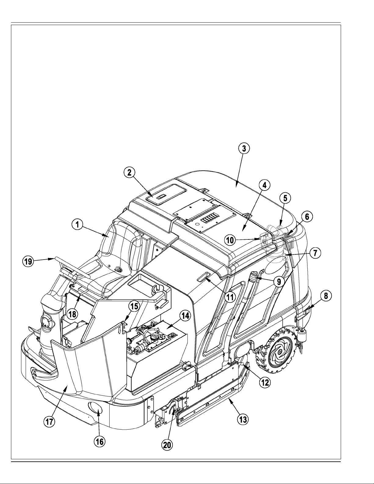
KNOW YOUR MACHINE
As you read this manual, you will occasionally run across a bold number or letter in parentheses - example: (2). These numbers refer to an item shown on these
pages unless otherwise noted. Refer back to these pages whenever necessary to pinpoint the location of an item mentioned in the text.
1 Operator’s Seat
2 Solution Tank Fill Cover
3 Engine Cover
4 Recovery Tank Cover
5 Engine Air Filter Service Indicator
6 Coolant Overfl ow Tank
7 Engine Air Filter
8 Engine Cover Latch
9 Recovery Tank Drain Hose
10 Recovery Tank Tilt Out Latch
11 Recovery Tank Tilt Out Grip
12 Left Side Skirt Latch
13 Left Side Skirt
14 Fuel Tank (petrol tank shown)
15 Fuel Tank Cover Latch
16 Head Light
17 Fuel Tank Cover
18 Operator Seat Adjustment Lever
19 Steering Wheel
20 Double Scrub Skirt Holder
A-6 - FORM NO. 56091008 - ER 1300, 1600
Page 7
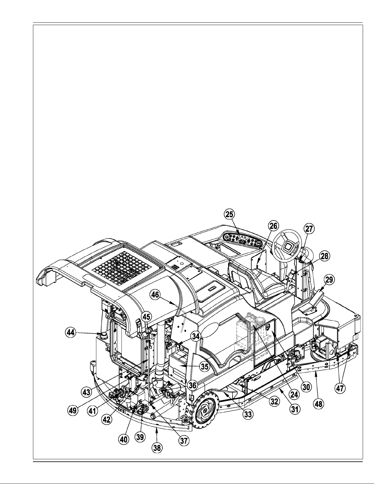
KNOW YOUR MACHINE
24 Detergent Cartridges (EcoFlex models only)
25 Control Panel
26 Circuit Breaker Panel (see Troubleshooting)
27 Steering Wheel Tilt Adjust Lever
28 Brake Pedal / Parking Brake
29 Drive Pedal, Directional/Speed
30 Detergent Cartridge Compartment
31 Right Side Skirt
32 Right Side Skirt Latch
33 Hopper
34 Tow Valve Lever
35 Battery
36 Solution Filter
37 Solution Tank Drain Hose
38 Squeegee Assembly
ENGLISH / A-7
39 Squeegee Height Adjust Knob
40 Squeegee Mount Wrench
41 Squeegee Tilt Adjust Knob
42 Engine Oil Filter
43 Engine Cover Prop Rod
44 Hydraulic Oil Reservoir Filler Cap
45 Oil Cooler Tilt Out Latch
46 Engine Oil Dipstick
47 Right Scrub Skirt Retainer Knobs
48 Right Scrub Skirt Assembly
49 Engine Oil Drain (under radiator)
FORM NO. 56091008 - ER 1300, 1600 - A-7
Page 8
A-8 / ENGLISH
KNOW YOUR MACHINE
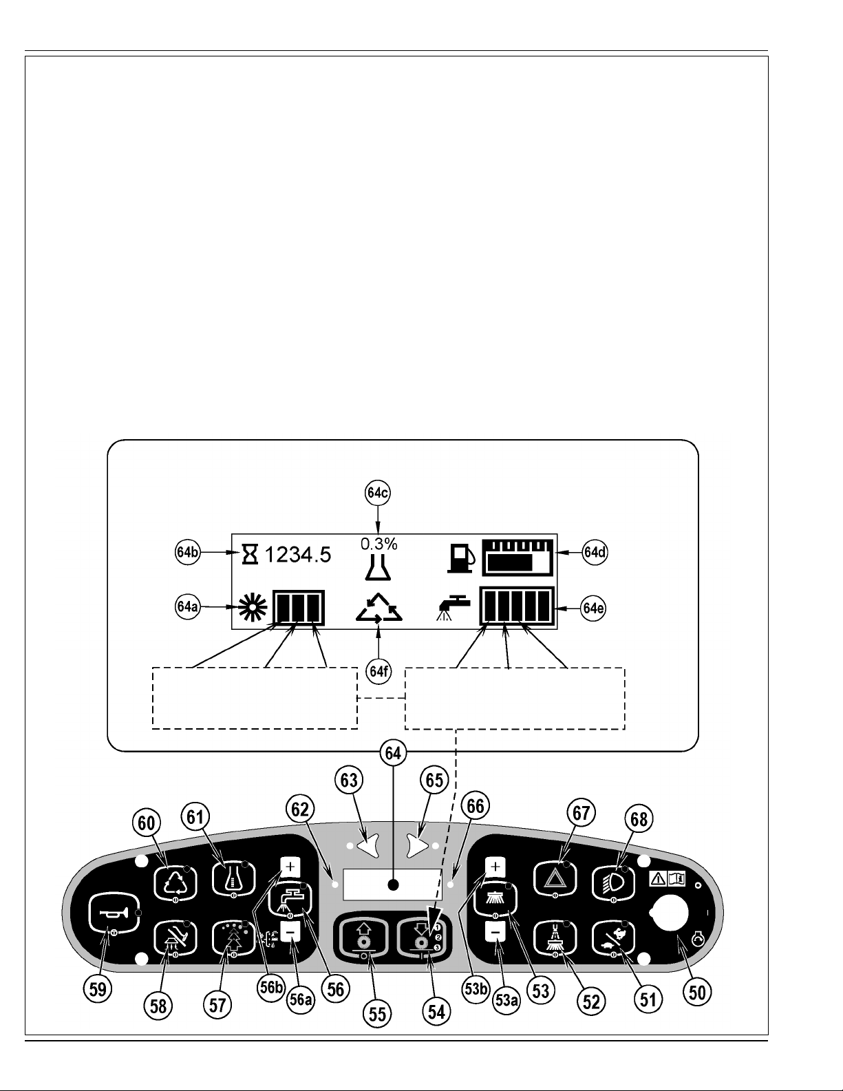
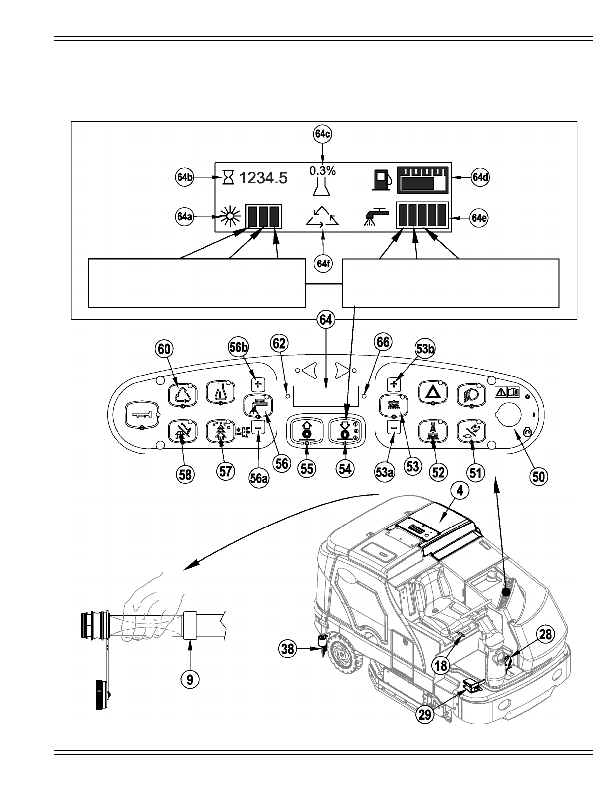
50 Key Switch
51 Engine Speed Switch
52 Dust Guard
53 Side Broom/Scrub ON / OFF Switch
53a Side Broom DOWN adjust Switch
53b Side Broom UP adjust Switch
54 Scrub ON / Scrub Mode Select
55 Scrub OFF
56 Solution Switch
56a Solution Flow Decrease Switch
56b Solution Flow Increase Switch
57 EcoFlex Switch
58 Vacuum/Wand Switch (see next page)
59 Horn Switch
60 Extended Scrub Switch (optional / see next page)
61 Detergent System (EcoFlex models only)
62 Warning Indicator Light (RED)
62a Parking Brake ON
62b Oil Pressure (Diesel)
62c Engine Service
62d Battery Low
62e Controller Fault
62f Hydraulic Temp
62g Low Fuel
62h Engine Temp
63 Left Turn Signal (optional)
64 Display
64a Scrub Pressure Indicator
64b Hour Meter
64c Detergent Indicator (if so equipped)
64d Fuel Gauge
64e Solution Flow Indicator
64f Extended Scrub Indicator (optional)
65 Right Turn Signal (optional)
66 Attention Indicator Light (YELLOW)
66a Solution Low
66b Hydraulic Filter Plugged
66c Non Critical Fault / Non Critical Engine Service
66d Glow Plug
66e Recovery Tank FULL
67 Emergency Flashers (optional)
68 Head Lights
(scrub 1) (scrub 2) (scrub 3)
press 1 time press 2 times press 3 times
A-8 - FORM NO. 56091008 - ER 1300, 1600
Flow Flow Flow
Rate 1 Rate 2 Rate 3
(scrub 1) (scrub 2) (scrub 3)
press 1 time press 2 times press 3 times
Page 9
ENGLISH / A-9
KNOW YOUR MACHINE
VACUUM / WAND SWITCH (58)
See Vac Wand Kit Instruction Sheet form number 56040944.
EXTENDED SCRUB SWITCH (60)
See Extended Scrub Kit Instruction Sheet form number 56040945.
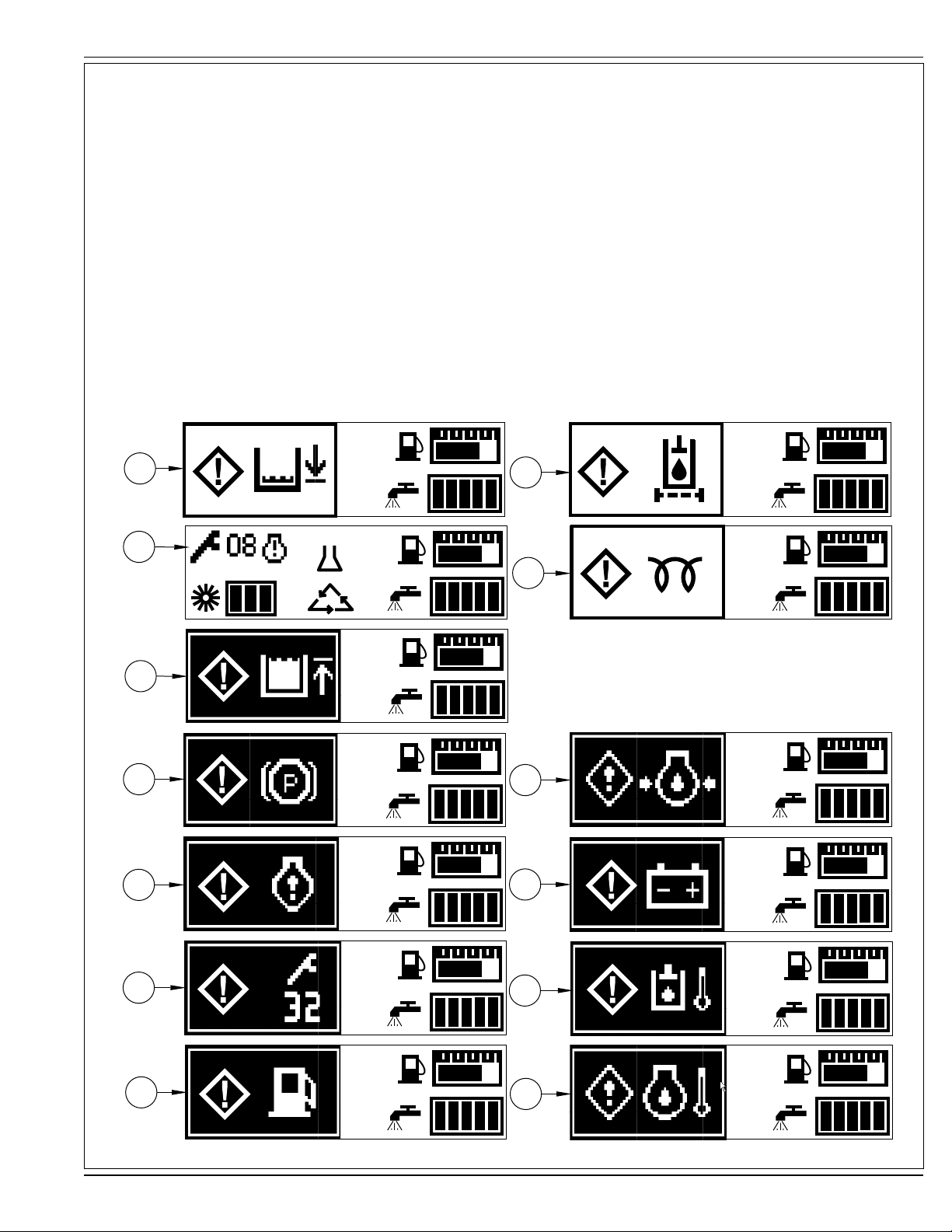
IF ANY OF THE WARNING / ATTENTION ICONS MARKED(X) BELOW ARE DISPLAYED PLEASE CONTACT YOUR ADVANCE
AUTHORIZED SERVICE CENTER.
66a
66c
X
66e
62a
62c
66b
X
300:1
66d
62b
X
62d
X
62e
X
62g
X
62f
X
62h
X
FORM NO. 56091008 - ER 1300, 1600 - A-9
Page 10
A-10 / ENGLISH
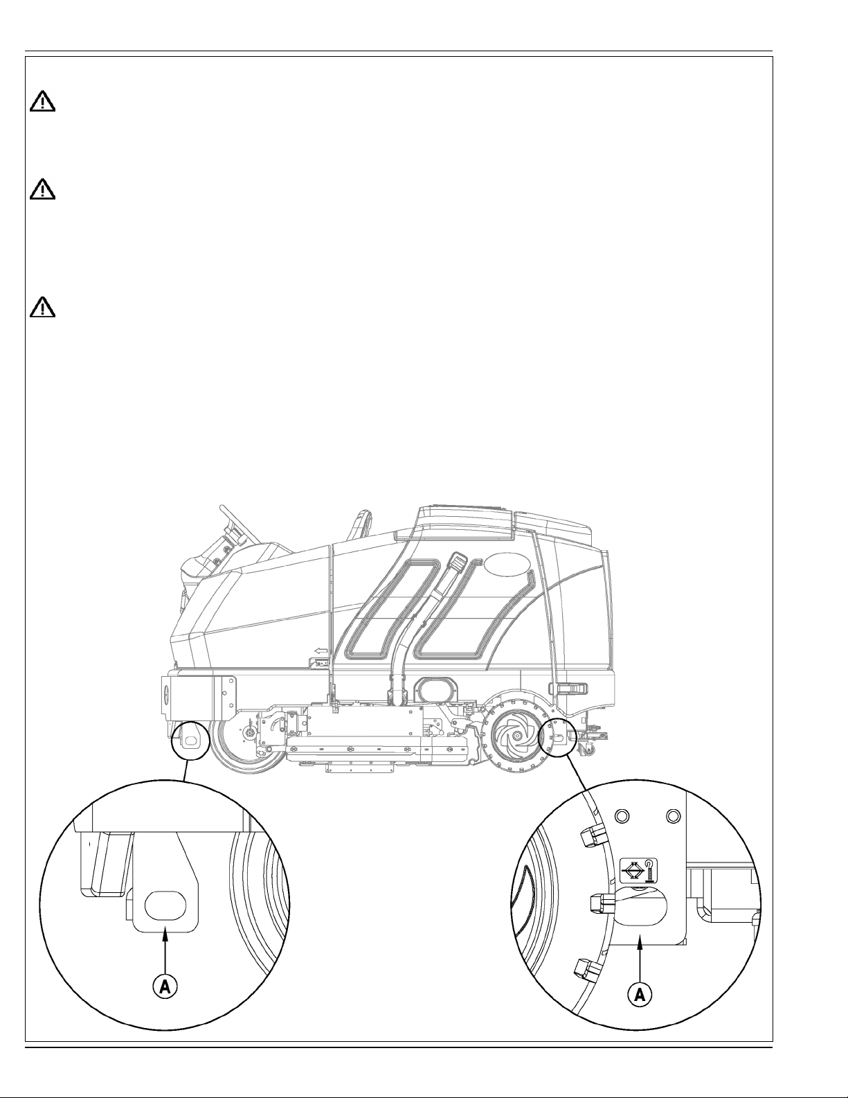
JACKING THE MACHINE
CAUTION!
Never work under a machine without safety stands or blocks to support the machine.
• When jacking the machine, do so at designated locations - see Tie Down / Jacking Locations (A) in Figure 1.
TRANSPORTING THE MACHINE
CAUTION!
Before transporting the machine on an open truck or trailer, make sure that . . .
• All access doors are latched securely.
• The machine is tied down securely - see Tie Down / Jacking Locations (A) in Figure 1.
• The machine Parking Brake (28) is set.
TOWING OR PUSHING A DISABLED MACHINE
CAUTION!
The machine’s drive propelling pump is manufactured with an adjustable tow valve. This valve prevents damage to the hydraulic
system when the machine is being towed/pushed short distances without use of the engine.
The tow valve is controlled by the Tow Valve Lever (34) which is accessed by opening and propping the Engine Cover (3). Pull The Tow Valve Lever (34) out; this
disengages the hydrostatic lock between the motor and pump.
The hydrostatic pump can be damaged if the machine is towed with the valve in the normal working position (Tow Valve Lever (34) pushed IN). Note: If the tow
valve is left in free wheeling position (Tow Valve Lever (34) pulled OUT) the hydrostatic pump can’t drive the machine FWD or REV. No damage will result, just
reset the valve to the normal working position by pushing the lever IN. Tow or push the machine no faster than a normal walking pace (2-3 miles per hour) and for
short distances only. If the machine is to be moved long distances the front drive wheel needs to be raised off the fl oor and placed on a suitable transport dolly.
FIGURE 1
A-10 - FORM NO. 56091008 - ER 1300, 1600
Page 11
ENGLISH / A-11
PRE-OPERATIONAL CHECKLIST
Before Each Use:
* Inspect the machine for damage, oil or coolant leaks.
* Squeeze the rubber dust cup on the Engine Air Filter (7) to release built-up dust.
* Check the engine coolant level (6).
* Check the engine oil level (46).
* Check the hydraulic oil level (44).
* Check the Fuel Gauge (64d) on the gasoline/petrol, and diesel models.
* Check the Fuel Gauge located on the LP tank for LPG model.
* Check the Air Filter Service Indicator (5).
In the Driver’s Seat:
* Be sure that you understand the operating controls and their functions.
* Adjust the seat to allow easy reach of all controls.
* Insert the Master Key and turn the Ignition Key Switch (50) to the ON position. Check for proper operation of the Horn (59), Hour Meter (64b) and Headlights
(68). Turn the Ignition Key Switch (50) OFF.
* Check the Brake Pedal (28). The pedal should be fi rm and should not go all the way down. The latch should hold the pedal when applied.
(Report all defects immediately to service personnel).
Plan Your Cleaning in Advance:
* Arrange long runs with a minimum of stopping or starting.
* Allow 2-3” (5.08-7.62cm) of scrub path overlap to ensure complete coverage.
* Avoid making sharp turns, bumping into posts, or scraping the side of the machine.
HYDRAULIC OIL
Open and prop the Engine Cover (3) to access the hydraulic oil reservoir. Remove the Fill Cap (44) from the tank and look to the bottom of the fi ller screen. If
the oil level is below the bottom of the fi ller screen, add 10W30 motor oil until the bottom of the fi ller screen is covered (oil level should not be higher than 1/2”
(12.7mm) above the bottom of the fi ller screen). Change the oil if major contamination from a mechanical failure occurs.
ENGINE OIL – GASOLINE / PETROL & LPG
Check the engine oil level when the machine is parked on a level surface and the engine is cool. Change the engine oil after the fi rst 35 hours of
operation and every 150 hours after that. Use any SF or SG rated oil meeting API specifi cations and suited to seasonal temperatures. Refer to
the Engine System section for oil capacities and additional engine specifi cations. Replace the oil fi lter with every oil change.
TEMPERATURE RANGE OIL WEIGHT
Above 60° F (15° C) SAE 10W-30
Below 60° F (15° C) SAE 5W-30
ENGINE OIL - DIESEL
Check the engine oil level when the machine is parked on a level surface and the engine is cool. Change the engine oil after the fi rst 35 hours
of operation and every 150 hours after that. Use CF, CF-4 or CG-4 oil meeting API specifi cations and suited temperatures (*important reference
the oil/fuel type note below for further diesel oil recommendations). Refer to the Engine System section for oil capacities and additional engine
specifi cations. Replace the oil fi lter with every oil change.
TEMPERATURE RANGE OIL WEIGHT
Above 77 °F (25 °C) SAE 30 or 10W-30
32 °F to 77 °F (0 °C to 25 °C) SAE 20 or 10W-30
Below 32 °F (0 °C) SAE 10W or 10W-30
* Diesel Lubricating Oil Note:
With the emission control now in effect, the CF-4 and CG-4 lubricating oils have been developed for use with a low-sulfur fuel used in on-road vehicle
engines. When an off-road vehicle engine runs on a high-sulfur fuel, it is advisable to employ the CF, CD or CE lubricating oil with a high total base number.
If the CF-4 or CG-4 lubricating oil is used with a high-sulfur fuel, change the lubricating oil at shorter intervals.
• Lubricating oil recommended when a low-sulfur or high-sulfur fuel is employed.
Fuel
Lubricating
Oil class
CF
CF-4
CG-4
O : Recommended X : Not recommended
Low sulfur
(0.5 % ≥)
OO
OX
OX
High sulfur Remarks
TBN ≥ 10
FORM NO. 56091008 - ER 1300, 1600 - A-11
Page 12
A-12 / ENGLISH
PRE-OPERATIONAL CHECKLIST
ENGINE COOLANT
CAUTION!
Do not remove the radiator cap when the engine is hot.
To check the engine coolant level, open and prop the Engine Cover (3) and observe the coolant level on the Coolant Recovery Tank (6). If the level is low add
automotive type anti-freeze appropriately diluted for the environment. Clean the radiator and oil cooler exteriors by washing with low-pressure water or using
compressed air every 30 hours. Service Note: The oil cooler tips out for easy cleaning.
ENGINE AIR FILTER
Check the Air Filter Service Indicator (5) before each use of the machine. Do not service the air fi lter unless the red fl ag is visible in the service indicator.
CAUTION!
When servicing the engine air fi lter elements, use extreme care to prevent loose dust from entering the engine. Dust can severely
damage the engine.
The engine air fi lter contains a Primary (outer) and a Safety (inner) fi lter element. The Primary Element may be cleaned twice before being replaced. The Safety
Element should be replaced every third time that the Primary Filter Element is replaced. Never attempt to clean the Inner Safety Element.
To clean the Primary Filter Element, unsnap the 2 clips at the end of the air fi lter and remove the end housing. Pull the primary element out. Clean the element
with compressed air (maximum pressure 100 psi) or wash it with water (maximum pressure 40 psi). DO NOT put the element back into the canister until it is
completely dry.
FUEL
WARNING!
• ALWAYS STOP THE ENGINE BEFORE FILLING THE FUEL TANK.
• DO NOT SMOKE WHILE FILLING THE FUEL TANK.
• FILL THE FUEL TANK IN A WELL-VENTILATED AREA.
• DO NOT FILL THE FUEL TANK NEAR SPARKS OR OPEN FLAME.
• USE ONLY THE FUEL SPECIFIED ON THE FUEL TANK DECAL.
On machines with diesel and gasoline engines, a decal near the Fuel Tank (14) fi ller neck shows the proper fuel to use in the machine. Before removing the cap
from the tank, wipe all dust and dirt from the cap and from the top of the tank to keep the fuel as clean as possible.
On machines with propane engines, a decal near the tank gives specifi c information about the proper type of tank to be used on the machine.
DIESEL ENGINE
Fill the tank with Number 2 Diesel Fuel if the machine will be used in an area where the temperature is 30° Fahrenheit (0° Celsius) or higher. Use Number 1
Diesel Fuel if the machine will be used in an area where the temperature is below 30° Fahrenheit (0° Celsius).
NOTE: If the diesel machine runs out of fuel completely, the fuel system must be bled before the engine can be re-started. To avoid this situation, fi ll the fuel tank
when the fuel gauge indicates 1/4 tank. Fuel tank capacity is 11 gallons (42 liters).
GASOLINE / PETROL ENGINE
FILL THE TANK WITH UNLEADED 87 OCTANE REGULAR GASOLINE. FUEL TANK CAPACITY IS 11 GALLONS (42 LITERS).
Note: Reference the separately supplied engine manufacture’s maintenance and operator manual for more detailed engine specifi cation and service data.
LPG ENGINE
Mount a standard 33 lb. liquid withdrawal propane tank on the machine, connect the fuel hose and open the shutoff valve on the tank. Wear gloves when
connecting or disconnecting the fuel hose. Shut the propane tank service valve OFF when the machine is not in use.
A-12 - FORM NO. 56091008 - ER 1300, 1600
Page 13
ENGLISH / A-13
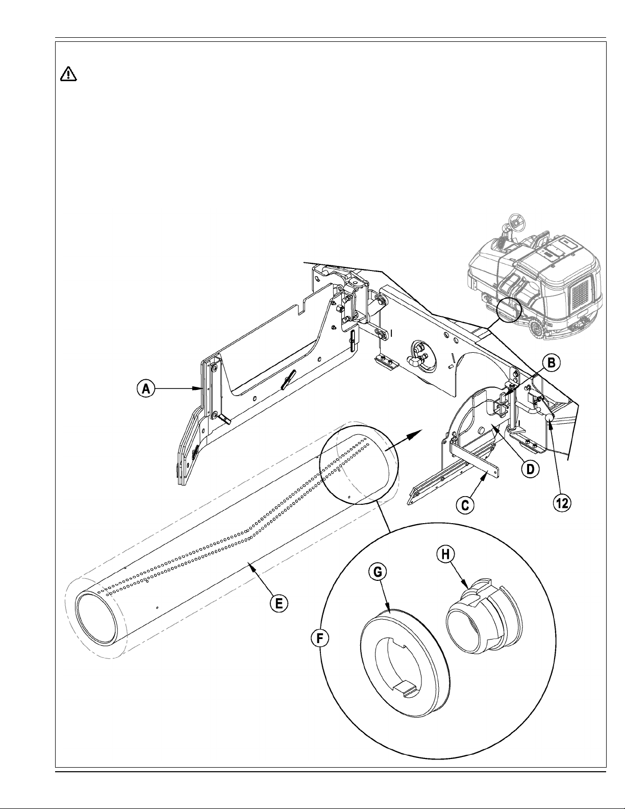
INSTALL THE BRUSHES
CAUTION!
Turn the key switch off (O) and remove the key, before changing the brushes, and before opening any access panels.
1 Make sure the Scrub Deck is in the RAISED position, the Key Switch (50) is off (O) and the Parking Brake (28) is set.
2 See Figure 2. Push down on the Side Skirt Latch (12 or 32) and swing the Skirt Assy (A) open as shown.
3 Lift up on Latch (B), swing Lever (C) out and pull to open the Idler Assembly (D).
4 Slide the Brush (E) into the housing, lift slightly, push and turn until it seats. NOTE: Figure 2 shows a closeup view (F) of the Brush Lugs (G) and the Brush
Drive Hub (H).
5 Swing the Idler Assembly (D) closed while holding Lever (C) at a 90 degree angle to the Idler.
6 Once the Idler Assembly (D) is closed, push Lever (C) in until Latch (B) can be slid back down in front of it.
7 Push down on the Side Skirt Latch (12 or 32), swing the Skirt Assy (A) closed and release the Latch.
NOTE: Refer to this section when rotating (fl ipping end-to-end) brushes according to the maintenance schedule.
FIGURE 2
FORM NO. 56091008 - ER 1300, 1600 - A-13
Page 14
A-14 / ENGLISH
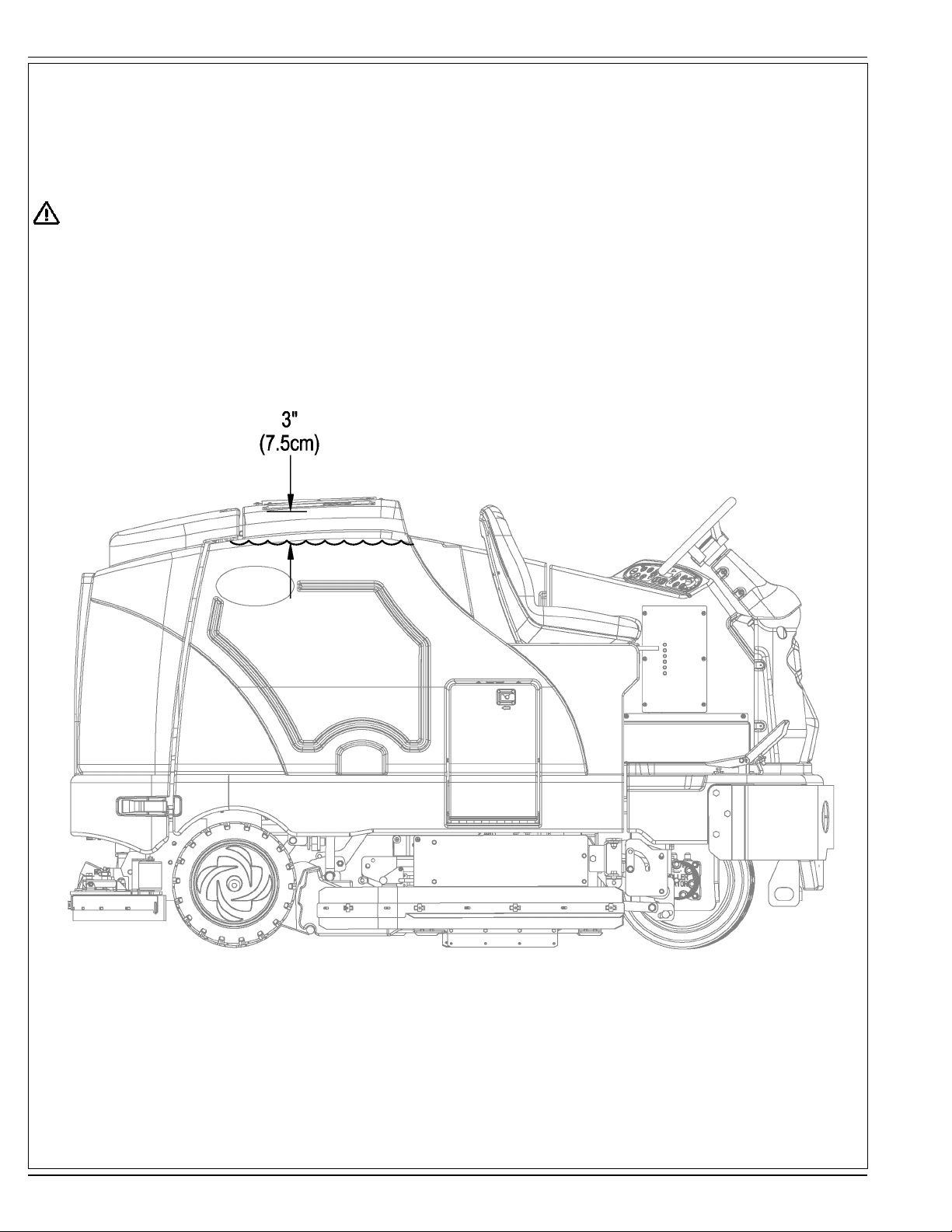
FILLING THE SOLUTION TANK
See Figure 3. Fill the solution tank with a maximum of 100 gallons (378.54 Liters) of cleaning solution. Do not fi ll the solution tank above 7.5 cm
(3 inches) from the bottom of the Solution Fill (2). The solution should be a mixture of water and the proper cleaning chemical for the job. Always
follow the dilution instructions on the chemical container label. NOTE: EcoFlex machines can either be used conventionally with detergent mixed
in the tank or the detergent dispensing system can be used. When using the detergent dispensing do not mix detergent in the tank, plain water
should be used.
CAUTION!
Use only low-foaming, non-fl ammable liquid detergents intended for machine application. Water temperature should not exceed 130
degrees Fahrenheit (54.4 degrees Celsius)
FIGURE 3
A-14 - FORM NO. 56091008 - ER 1300, 1600
Page 15

ENGLISH / A-15
OPERATING THE MACHINE
The ER 1300 / 1600 is a rider-type automatic fl oor scrubbing machine. It is designed to lay down cleaning solution, scrub the fl oor, and vacuum
dry all in one pass.
The controls on the ER 1300 / 1600 were designed with one touch operation in mind. For single pass scrubbing the user can simply depress one
switch and all scrub functions on the machine will be activated.
NOTE: Bold numbers in parentheses indicate an item illustrated on pages 6-9.
NOTE!: MAKE SURE THE FOOT PEDAL IS IN THE NEUTRAL POSITION. THE ENGINE WILL NOT CRANK IF THE FOOT PEDAL IS NOT IN
NEUTRAL. EITHER THE SEAT SWITCH MUST BE CLOSED OR THE BRAKE ENGAGED BEFORE THE ENGINE WILL START.
STARTING THE DIESEL ENGINE
1 Turn the key switch (50) clockwise to the RUN (ON) position. The glow plugs will activate for 10 seconds as indicated by the attention
indicator (66) and the glow plug icon (66d) on the display. If the engine is already warm, turn the key switch to the start position to crank the
engine. If the engine is cold, wait for the attention indicator and glow plug icon to turn off before cranking the engine. The engine should start
immediately. If the engine does not start within 15 seconds release the key, wait for approximately one minute and repeat the above steps.
2 Let the engine run at IDLE speed for fi ve minutes before using the machine.
3 Press the Engine Speed Switch (51) once to switch to FULL THROTTLE and move the machine around for two to three minutes at slow
speed to warm up the hydraulic system.
STARTING THE GASOLINE / PETROL ENGINE
1 Turn the Ignition Key Switch (50) clockwise to the START position and release it as soon as the engine starts. If the engine does not start
after cranking for 15 seconds, release the key, wait for 1 minute, then try again.
2 Let the engine run at “IDLE” speed for 5 minutes before using the machine.
3 Push the Engine Speed Switch (51) once to switch to “FULL THROTTLE” and move the machine around for 2 or 3 minutes at a slow speed to
warm up the hydraulic system.
STARTING THE LPG ENGINE
1 Open the service valve on the LP fuel tank.
2 Turn the Ignition Key Switch (50) clockwise to the START position and release it as soon as the engine starts. If the engine does not start
after cranking for 15 seconds, release the key, wait for 1 minute, then try again.
3 Let the engine run at “IDLE” speed for 5 minutes before using the machine.
4 Push the Engine Speed Switch (51) once to switch to “FULL THROTTLE” and move the machine around for 2 or 3 minutes at a slow speed to
warm up the hydraulic system.
ALWAYS operate the machine with the Engine Speed Switch at full throttle. Use the Drive Pedal (29) not the Engine Speed Switch (51) to
control the speed of the machine. The speed of the machine will increase as the pedal is pushed closer to the fl oor. Do not press the Drive Pedal
(29) until the engine has started.
NOTE!: If the operator leaves the seat without setting the brake, the engine will be turned off.
Engine Speed Switch (51):
There are three engine speed settings that can be selected by the engine speed switch (51) on the control panel.
1 “Idle” (1200 RPM – Petrol / LPG) (1300 RPM – Diesel). Use for warm up and cool down. The engine speed switch light will be off.
2 “Run” (2200 RPM). Use for transporting and most scrubbing operations. The engine speed light will be on.
3 “Turbo” (2400 RPM). Use only for heavy engine load situations such as heavy scrubbing on inclines. The engine speed light will be on.
4 To select between Idle and Run press and release the engine speed switch.
5 To select the Turbo speed, fi rst set the speed to Run. Then press and hold the engine speed switch for 2 seconds. To go back to Run speed,
press the switch again.
6 The ER 1300 / 1600 has an automatic idle feature that will reduce the engine speed to idle when the foot pedal (29) has been in the neutral
position for 20 seconds or more. The selected engine speed will automatically resume when the foot pedal is moved from neutral. If the
engine speed switch (51) is pressed while in idle-override, the automatic idle feature will be temporarily disabled until the next time the foot
pedal is moved from the neutral position. This can be useful during troubleshooting or if it is desired to let the machine run at full speed for
warming up.
FORM NO. 56091008 - ER 1300, 1600 - A-15
Page 16

A-16 / ENGLISH
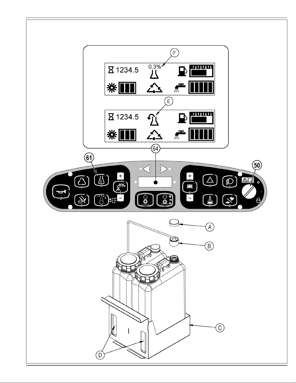
DETERGENT SYSTEM PREPARATION AND USE (ECOFLEX MODELS ONLY)
The Detergent Cartridges (24) are located inside of the Detergent Cartridge Compartment (30). Fill the detergent cartridge with a maximum of
2.2 gallons (8.32 Liters) of detergent. SERVICE NOTE: Remove the detergent cartridge from the detergent box prior to fi lling to avoid spilling
detergent on the machine.
It is recommended that a separate cartridge be used for each detergent you plan to use. The detergent cartridges have a white decal on them so
you can write the detergent name on each cartridge to avoid mixing them up. When installing a new cartridge, remove the Cap (A) and place the
cartridge in the detergent box. Install the Dry Break Cap (B) as shown.
The system should be purged of previous detergent when switching to a different detergent. SERVICE NOTE: Move machine over fl oor drain
before purging because a small amount of detergent will be dispensed in the process.
To Purge When Changing Chemicals(SCRUB SYSTEM MUST BE OFF):
1 Disconnect and remove the detergent cartridge.
2 Turn the key switch (50) to the RUN (ON) position. Wait a few seconds for the start-up sequence to fi nish.
3 Press and hold the detergent switch (61) for approximately 2 seconds. Release the switch when the chemical purge icon (E) appears on the
display and the indicator on the detergent switch (61) starts fl ashing. NOTE: Once activated the purge process takes at least 20 seconds.
See illustration on next page for Detergent System indicators. Normally one purge cycle is adequate to purge the system.
To Purge Weekly(SCRUB SYSTEM MUST BE OFF):
1 Disconnect and remove the detergent cartridge. Install and connect a Cartridge fi lled with clean hot water.
2 Turn the key switch (50) to the RUN (ON) position. Wait a few seconds for the start-up sequence to fi nish.
3 Press and hold the detergent switch (61) for approximately 2 seconds. Release the switch when the chemical purge icon (E) appears on the
display and the indicator on the detergent switch (61) starts fl ashing. NOTE: Once activated the purge process takes at least 20 seconds.
See illustration on next page for Detergent System indicators. Normally one purge cycle is adequate to purge the system.
The Detergent Box (C) has Detergent Level Viewing Slots (D) for referencing the amount of detergent remaining in the cartridge(s). When the
detergent level is nearing the bottom of this slot it is time to refi ll or replace the cartridge(s).
Detergent Ratio (SCRUB SYSTEM MUST BE ON):
The detergent ratio default is .04%. The detergent mixture rate may be adjusted by pressing and holding the detergent switch (61) for two
seconds. Release the switch once the detergent switch light begins fl ashing. While the light is fl ashing, pressing and releasing the detergent
switch will cycle through the available percentages (.03%, .04%, .05%, .07%, .08%, 1.0%, 1.5%, 2.0%, 3.0%, or 3.8%). Once the desired
percentage is displayed on the screen (F), stop and it will lock in after 3 seconds.
The detergent mixture (F) will always be displayed when the detergent system is on.
Once set, the detergent fl ow rate automatically increases and decreases with the solution fl ow rate but the detergent ratio remains the same. If
an operator would prefer the fl exibility of setting different detergent dilutions ratios for different solution fl ow rates this specifi
found in the service manual. During scrubbing, the detergent system can be turned off at any time by pressing the Detergent ON/OFF Switch (61)
to allow scrubbing with water only. No detergent is dispensed until the scrub system is activated and the Drive Pedal (29) pushed forward.
SERVICE NOTE: Follow the “To Purge Weekly” instructions above if the machine is going to be stored for an extended period of time or if you plan
to discontinue use of the detergent (EcoFlex) system.
c programming can be
A-16 - FORM NO. 56091008 - ER 1300, 1600
Page 17
DETERGENT SYSTEM PREPARATION AND USE (ECOFLEX MODELS ONLY)
FIGURE 4
ENGLISH / A-17
FORM NO. 56091008 - ER 1300, 1600 - A-17
Page 18

A-18 / ENGLISH
SCRUBBING
WARNING!
Be sure you understand the operator controls and their functions.
While on ramps or inclines, avoid sudden stops when loaded. Avoid abrupt sharp turns. Use low speed down hills.
To Scrub...
Follow the instructions in preparing the machine for use section of this manual. Start the engine following the instructions in the appropriate “Starting the …
Engine” section.
1 See Figure 5. While seated on the machine, adjust the seat and steering wheel to a comfortable operating position using the adjustment controls (18 & 27).
2 Release the Parking Brake (28). To transport the machine to the work area, apply even pressure with your foot on the front of the Drive Pedal (29) to go forward or the
rear of the pedal for reverse. Vary the pressure on the foot pedal to obtain the desired speed.
3 Press the Solution Switch (56) and hold for 5 seconds to pre-wet the fl oor. NOTE: This will help prevent scarring of the fl oor surface when starting to scrub with dry
brushes. This must be done prior to pressing the Scrub ON Switch (54).
4 Press the Scrub ON Switch (54) once for Light Scrub (1), twice for Medium Scrub (2) or three times for Heavy Scrub (3) mode. Both the solution fl ow and detergent
(EcoFlex models) fl ow have 3 presets that coincide with the 3 scrub modes (see Display Panel (64)). The right side scrub brush pressure is also affected when
pressing this switch.
NOTE: The solution fl ow rate can be overridden simply by pressing the Solution Flow Decrease or Increase Switches (56a / 56b). Any subsequent scrub pressure
adjustments will reset the solution fl ow rate to correspond with the scrub pressure.
NOTE: The scrub, solution, vacuum, detergent (EcoFlex models) and side broom(s) / brush systems are automatically enabled when the Scrub ON Switch (54) is
pressed. Any individual system can be turned OFF or back ON by simply pressing its switch at any time during scrubbing. If you have installed the Extended Scrub
Kit, it will not be automatically activated. You must press the Extended Scrub Switch (60) to activate this system. The Extended Scrub system will not turn ON until the
water level in the recovery tank reaches a certain level and the clean solution has been used up.
5 When the Scrub ON Switch (54) is selected, the brushes, squeegee and side broom(s) / brush are automatically lowered to the fl oor. The scrub, solution, vacuum,
detergent (EcoFlex models) and side broom(s) / brush systems all start when the Drive Pedal (29) is activated.
NOTE: When operating the machine in reverse the squeegee automatically raises and the solution fl ow will stop.
6 Begin scrubbing by driving the machine forward in a straight line at a normal walking speed and overlap each path by 2-3” (5.08-7.62cm). Adjust the machine speed
and solution fl ow when necessary according to the condition of the fl oor.
The side broom height can be adjusted by pressing the Side Broom DOWN and UP Switches (53a/53b). The side broom(s) will return to the last used position each
time the sweep system is turned on. The side brooms have a misting function (Dust Guard) (52) for use in dusty conditions. NOTE: The “Dust Guard” (52) comes
on automatically with the Side Brooms (53) but can be turned OFF by pressing (52). NOTE: If equipped with Extended Scrub, the “Dust Guard” will shut off when the
machine runs out of clean solution.
CAUTION!
To avoid damaging the fl oor, keep the machine moving while the brushes are turning (the brushes will turn OFF after a 2 second delay when the
drive pedal is placed in the neutral position).
Raise scrub deck and side scrub brush, if so equipped, when crossing speed bumps. Do not attempt to operate the scrub deck or side brush in the
down position when crossing speed bumps. Hydraulic pressure pushes down on the brushes and attempting to operate in the scrub mode over a
speed bump can cause damage to the machine.
7 When scrubbing, check behind the machine occasionally to see that all of the waste water is being picked up. If there is water trailing the machine, you may be
dispensing too much solution, the recovery tank may be full, or the squeegee tool may require adjustment.
8 The machine defaults to the EcoFlex cleaning mode (if detergent is installed) (EcoFlex Switch Indicator is lit) conserving solution and detergent. Press the EcoFlex
Switch (57) to override the EcoFlex cleaning mode and temporarily increase scrub pressure, solution fl ow and the detergent percentage. This will cause the indicator
to fl ash for one minute, solution fl ow rate will increase to the next level, scrub pressure will increase to the next level and the detergent ratio will increase to the next
higher percentage from the last one used (detergent system will be turned on if it was off).
NOTE: Pressing and holding the EcoFlex Switch (57) for 2 seconds disables the EcoFlex system. The only way to re-enable is to push the EcoFlex Switch (57) again.
Cycling the Key Switch (50) does not re-enable the system. The EcoFlex system will only function if the Scrub System (54) has been enabled.
9 For extremely dirty fl oors, a one-pass scrubbing operation may not be satisfactory and a “double-scrub” operation may be required. This operation is the same as a
one-pass scrubbing except on the fi rst pass the squeegee is in the up position (press the Vacuum Switch (57) to raise the squeegee). This allows the cleaning solution
to remain on the fl oor to work longer. The Side Skirts (13 & 31) can also be raised for double scrubbing if needed with the Skirt Holders (20). The fi nal pass is made
over the same area, with the squeegee and skirts lowered to pick up the accumulated solution.
10 The recovery tank has a fl oat switch that causes ALL systems to turn OFF except the drive system when the recovery tank is full. When this fl oat switch is activated,
the recovery tank must be emptied. The machine will not pick up water or scrub with the fl oat switch activated.
NOTE: The Attention Indicator Light (66) will light up YELLOW and the Recovery Full Icon (66e) will display when the fl oat switch is activated. If the control repeatedly
gives a full indication when the tank is not full check to make sure the fl oat moves freely.
11 When the operator wants to stop scrubbing, press the Scrub OFF Switch (55) once. This will automatically stop the scrub brushes, side broom(s) / brush, solution fl ow
and detergent fl ow. The scrub deck and side broom(s) / brush will raise up. The squeegee will raise up after a brief delay and the vacuum will stop after a brief delay
(this is to allow any remaining water to be picked up without turning the vacuum back on).
12 Drive the machine to a designated waste water “DISPOSAL SITE” and empty the recovery tank. To empty, pull the Drain Hose (9) from its storage area, then remove
the plug (hold the end of the hose above the water level in the tank to avoid sudden, uncontrolled fl ow of waste water). The Recovery Tank Drain Hose (9) can be
squeezed to regulate the fl ow. Refi ll the solution tank and continue scrubbing.
NOTE: Make sure the Recovery Tank Cover (4) and the Recovery Tank Drain Hose (9) cap are properly seated or the machine will not pick-up water correctly.
SERVICE NOTE: Refer to the service manual for optional programmability.
A-18 - FORM NO. 56091008 - ER 1300, 1600
Page 19
OPERATING THE MACHINE
FIGURE 5
ENGLISH / A-19
(scrub 1) (scrub 2) (scrub 3)
press 1 time press 2 times press 3 times
Flow Flow Flow
Rate 1 Rate 2 Rate 3
(scrub 1) (scrub 2) (scrub 3)
press 1 time press 2 times press 3 times
FORM NO. 56091008 - ER 1300, 1600 - A-19
Page 20

A-20 / ENGLISH
AFTER USE
1 When fi nished scrubbing, press the Scrub Off Switch (55). This will automatically raise, retract and stop all the machine systems (brush, squeegee, vacuum, solution and
detergent (EcoFlex models)). Then drive the machine to a service area for daily maintenance and review of other needed service up keep.
2 To empty the solution tank, remove the Solution Drain Hose (37) from its storage clamp. Direct the hose to a designated “DISPOSAL SITE” and remove the cap. Rinse the tank
with clean water.
3 To empty the recovery tank, pull the Recovery Tank Drain Hose (9) from its storage area. Direct the hose to a designated “DISPOSAL SITE” and remove the plug (hold the end
of the hose above the water level in the tank to avoid sudden, uncontrolled fl ow of waste water). The Recovery Tank Drain Hose can be squeezed to regulate the fl ow. Rinse
the recovery tank with clean water. Inspect the recovery and vacuum hoses; replace if kinked or damaged.
4 Remove the brushes, remove any string or banding that is wrapped around them, rinse in warm water and stand on end to dry. NOTE: Brushes should be fl ipped “end for end”
and rotated “front to back” daily for longest life.
5 Remove the squeegee, rinse it with warm water and re-install on mount.
6 Remove the Hopper (33) and clean thoroughly. Remove from the right side of the machine by opening the skirt, disconnecting the vacuum hose and then pulling out. NOTE:
Reconnect vacuum hose after re-installing.
7 Check the maintenance schedule and perform any required maintenance before storage
SHUTTING DOWN THE DIESEL / GASOLINE ENGINE
1 Put all controls to the OFF position.
2 Raise the squeegee, the scrub brushes, and the brooms.
3 Push the Engine Speed Switch (51) to change to “Idle” speed and let the engine idle for 30 seconds.
4 Apply the Parking Brake (28).
5 Turn the Key Ignition Switch (50) OFF and remove the key.
SHUTTING DOWN THE LPG ENGINE
1 Put all controls to the OFF position.
2 Raise the squeegee, the scrub brushes, and the brooms.
3 Turn the service valve on LP gas tank OFF.
4 Push the Engine Speed Switch (51) to change to “Idle” speed and let the engine idle until all the LP gas is dispelled from the line.
5 Apply the Parking Brake (28).
6 Turn the Key Ignition Switch (50) OFF and remove the key.
IMPORTANT NOTE: During normal operation the engine will continue to run for a short period of time (1-3 seconds) after turning the key OFF until all fuel is dispelled from fuel
system.
MAINTENANCE SCHEDULE
Keep the machine in top condition by following the maintenance schedule closely. Maintenance intervals given are for average operating conditions. Machines used in severe
environments may require service more often.
MAINTENANCE ITEM DAILY WEEKLY
Perform the “After Use” maintenance steps X
Check parking brake X
Check engine oil X
*Check / Clean / Rotate & fl ip the Brushes X
Check fi lter indicator and lights (hyd & air) X
Check engine coolant level X
Check hydraulic oil level X
Drain / Check / Clean Tanks & Hoses X
Check / Clean the Squeegee X
Clean the Hopper X
Purge Detergent System (EcoFlex only) X
Inspect main scrub head skid plates(replace if worn to 1/8”) X
MAINTENANCE ITEM 15 hrs. 30 hrs. 150 hrs. 300 hrs. 500 hrs. 1000 hrs.
Inspect and clean the Solution Filter X
Clean radiator and oil cooler X
Side Broom Maintenance X
Clean solution trough X
Inspect scrub housing skirts X
Perform engine maintenance X
Inspect and grease steering rack X
Change the hydraulic “charge” oil fi lter X
Change reservoir hydraulic oil and fi lter X
Flush the radiator X
Engine fuel fi lter(s) gas or lpg X
* See “INSTALL THE BRUSHES” section.
A-20 - FORM NO. 56091008 - ER 1300, 1600
Page 21

LUBRICATING THE MACHINE – FIGURE 6
Once a month, pump a small amount of grease into each grease fi tting on the machine until grease seeps out around the bearings.
Grease fi tting locations (or apply grease to) (A):
• Squeegee Caster Wheel Axle and Pivot
• Steering Rack
• Squeegee mount angle adjustment knob threads
Once a month, apply light machine oil to lubricate the (B):
• Squeegee tool end wheels
• Fuel Tank Cover Latch
• Recovery Tank Latch
• EcoFlex Cover Latch
• Brake Pedal (parking brake) linkage
FIGURE 6
ENGLISH / A-21
FORM NO. 56091008 - ER 1300, 1600 - A-21
Page 22

A-22 / ENGLISH
SIDE BROOM MAINTENANCE
The side broom(s) move dirt and debris away from walls or curbs and into the path of the main brushes. Adjust the side broom(s) so that the bristles are
contacting the fl oor from the (A) to (B) area shown in Figure 7 when the broom is down and running.
To adjust the Side Brooms...
1 The side broom(s) are adjusted simply by pressing either the Side Broom DOWN Switch (53a) or the Side Broom UP Switch (53b). NOTE: Broom setting
resumes each time brooms are lowered but adjustment will be needed as brooms wear or are replaced.
NOTE: The machine should be stored with the Side Brooms in the raised position. The Side Brooms should be replaced when the bristles are worn to a length of
3 inches (7.62 cm) or they become ineffective.
To replace a Side Broom...
1 Raise the Side Broom(s).
2 Remove the large Thumb Nut (C) and remove the Side Broom (D). NOTE: The right side Thumb Nut (C) has right handed threads and the left side Thumb
Nut (C) has left handed threads.
3 Install the new broom by sliding it UP onto the shaft and re-install the Thumb Nut (C).
FIGURE 7
A-22 - FORM NO. 56091008 - ER 1300, 1600
Page 23

ENGLISH / A-23
SQUEEGEE MAINTENANCE
If the squeegee leaves narrow streaks or water, the blades may be dirty or damaged. Remove the squeegee, rinse it under warm water and inspect the blades.
Reverse or replace the blades if they are cut, torn, wavy or worn.
To Reverse or Replace the Rear Squeegee Wiping Blade...
1 See Figure 8. Raise the squeegee tool off the fl oor, then unsnap the Center Latch (A) on the squeegee tool.
2 Remove the Tension Straps (B).
3 Slip the rear blade off the alignment pins.
4 The squeegee blade has 4 working edges as shown below. Turn the blade so a clean, undamaged edge faces toward the front of the machine. Replace the
blade if all 4 edges are nicked, torn or worn to a large radius.
5 Install the blade, following the steps in reverse order and adjust the squeegee tilt.
To Reverse or Replace the Front Squeegee Blade...
1 Raise the squeegee tool off the fl oor, then loosen the (2) Squeegee Mount Wrenches (40) on top of the squeegee and remove the Squeegee tool (38) from
the mount.
2 Remove both rear Tension Straps fi rst.
3 Remove all the wing nuts that hold the front blade in place, then remove tension strap and blade.
4 The squeegee blade has 4 working edges as shown below. Turn the blade so a clean, undamaged edge faces toward the front of the machine. Replace the
blade if all 4 edges are nicked, torn or worn to a large radius.
5 Install the blade, following the steps in reverse order and adjust the squeegee tilt.
SERVICE NOTE: Depending on the position of the Squeegee Mount Wrenches (40), you may not be able to rotate the wrench far enough to loosen or tighten
depending on which you are trying to do. In this case, simply lift UP on the Handle (C) and rotate the wrench in the direction necessary to acquire adequate turning
space and then allow the wrench to drop back DOWN into place on the hex. You can then either tighten or loosen as needed.
SQUEEGEE ADJUSTMENT
There are two squeegee tool adjustments possible, angle and height.
Adjusting the Squeegee Angle
Adjust the squeegee angle whenever a blade is reversed or replaced, or if the squeegee is not wiping the fl oor dry.
1 Park the machine on a fl at, even surface.
2 Lower the squeegee, move the machine ahead slightly and adjust the squeegee tilt and height using the Squeegee Tilt Adjust Knob (41) and Squeegee
Height Adjust Knobs (39) so that the rear squeegee blade touches the fl oor evenly across its entire width and is bent over slightly as shown in the squeegee
cross section.
FIGURE 8
FORM NO. 56091008 - ER 1300, 1600 - A-23
Page 24

A-24 / ENGLISH
SIDE SKIRT MAINTENANCE
CAUTION!
Turn the key switch off (O) and remove the key, before changing the brushes, and before opening any access panels.
The side skirt’s function is to channel the waste water to the squeegee, helping contain the water within the machines cleaning path. During normal use the blades
will wear in time.
To reverse or replace the scrub system side skirt(s) ...
1 See Figure 9. Push down on the Side Skirt Latch (12 or 32) and swing the Skirt Assy (A) open as shown.
2 Remove all the hardware that holds the blades to the skirt housings. NOTE: The main blades on each skirt assembly are held on with Tool-less Retainers.
Simply loosen the large Wing nuts (B) and then turn the Knobs (C) on the outside of the skirt assembly until they are horizontal and push through the slots.
The small inside Blade (D) is held on by (4) screws.
3 The skirt blades have 4 working edges as shown. Turn the blades so a clean, undamaged edge faces toward the center of the machine. Replace the blades
as a set if all 4 edges are nicked, torn or worn excessively.
SIDE SKIRT TILT ADJUSTMENT
The side skirt assemblies may periodically need to have their tilt in relation to the fl oor adjusted.
1 Make sure the scrub deck is in the raised position.
2 To adjust, loosen Nut (E), loosen Nuts (F) and then turn Screws (G & H) as follows.
Turn Screw (G) clockwise and Screw (H) counter-clockwise to lower the rear of the skirt assembly.
Turn Screw (G) counter-clockwise and Screw (H) clockwise to raise the rear of the skirt assembly.
NOTE: Initial tilt adjustment should be parallel to the fl oor with the deck raised. Make small adjustments to obtain good blade wiping. Do not lower the rear of the
blades too much to where they fold over excessively and cause unneeded blade wear.
FIGURE 9
A-24 - FORM NO. 56091008 - ER 1300, 1600
Page 25

DEBRIS HOPPER MAINTENANCE
CAUTION!
Turn the key switch off (O) and remove the key, before opening any access panels.
1 See Figure 10. Push down on the Right Side Skirt Latch (32) and swing the Skirt Assy (A) open as shown.
2 Disconnect the small vacuum hose from the Screen (B) and slide the entire Hopper (C) out of the machine.
3 Remove the Screen (B) from the Hopper (C) and thoroughly rinse both to clear debris.
ENGLISH / A-25
FIGURE 10
FORM NO. 56091008 - ER 1300, 1600 - A-25
Page 26

A-26 / ENGLISH
TROUBLESHOOTING
If the possible causes listed below are not the source of trouble, it is a symptom of something more serious. Contact your Nilfi sk Service Center immediately for
service.
TRIPPING THE CIRCUIT BREAKERS
The circuit breakers are located on the Circuit Breaker Panel in the operator’s compartment; they protect electrical circuits and motors from damage due to
overload conditions. If a circuit breaker trips, try to determine the cause.
VACC1 Circuit Breaker (CB1 / 20 Amp) Possible cause may be:
1 Electrical short circuit (have your Nilfi sk Service Center or qualifi ed electrician check the machine)
VACC2 Circuit Breaker (CB2 / 20 Amp) Possible cause may be:
1 Electrical short circuit (have your Nilfi sk Service Center or qualifi ed electrician check the machine)
VACC3 Circuit Breaker (CB3 / 15 Amp) Possible cause may be:
1 Electrical short circuit (have your Nilfi sk Service Center or qualifi ed electrician check the machine)
VACC4 Circuit Breaker (CB4 / 20 Amp) Possible cause may be:
1 Electrical short circuit (have your Nilfi sk Service Center or qualifi ed electrician check the machine)
VACC5 Circuit Breaker (CB5 / 10 Amp) Possible cause may be:
1 Electrical short circuit (have your Nilfi sk Service Center or qualifi ed electrician check the machine)
Ignition Circuit Breaker (CB 6 / 15 Amp) Possible cause may be:
1 Electrical short circuit (have your Nilfi sk Service Center or qualifi ed electrician check the machine)
Once the problem has been corrected, push the button in to reset the circuit breaker. If the button does not stay in, wait 5 minutes and try again. If the circuit
breaker trips repeatedly, call your Nilfi sk Service Center for service.
VACC1 Circuit Breaker (CB1)
Right Rear Stop/Turn Lamp
Left Rear Stop/Turn Lamp
Right Front Turn Lamp
Left Front Turn Lamp
Rear Tail Lamps
Head Lamps
VACC2 Circuit Breaker (CB2)
Wash Hose Solution Pump (M8)
Side Sweep Mist Pump (M5)
VACC3 Circuit Breaker (CB3)
Side Sweep Lift Actuator Motor (M7)
VACC4 Circuit Breaker (CB4)
Scrub Brush Solenoid (L4)
Scrub Pressure Down (L5)
Scrub Cylinder Lock Solenoid (L6)
Scrub Pressure Up (L7)
Side Sweep / Scrub Solenoid (L8)
Side Scrub Lift Solenoid (L9)
Main Solution Solenoid Valve (L10)
Side Scrub Solution Solenoid Valve (L11)
Extended Scrub Water Solution Solenoid
Chemical Pump
VACC5 Circuit Breaker (CB5)
Vacuum Motor Solenoid (L1)
Squeege Down Solenoid (L3)
Squeege Up Solenoid (L3)
Main Solution Pump (M4)
Extended Scrub Pump (M6)
IGN Circuit Breaker (CB6)
Glow Plug Relay
Main Power Relay
Backup Audible Alarm
Horn
Engine System (fuel pump and ignition system)
Dash Board Panel
A-26 - FORM NO. 56091008 - ER 1300, 1600
Page 27

GENERAL MACHINE TROUBLESHOOTING
Problem Possible Cause Remedy
Poor water pick-up Worn or torn squeegee blades Reverse or replace
Squeegee out of adjustment Adjust so blades touch fl oor evenly
across entire width
Recovery tank full Empty recovery tank
Recovery tank drain hose leak Secure drain hose cap or replace
Recovery tank cover gasket leak Replace gasket / Seat cover properly
Debris caught in squeegee Clean squeegee tool
Vacuum hose clogged Remove debris
Using too much solution Reduce fl ow via control panel solution button
Poor scrubbing performance Worn brush Rotate or replace brushes
Wrong brush type Consult Nilfi sk
Wrong cleaning chemical Consult Nilfi sk
Moving machine too fast Slow down
Not using enough solution Increase fl ow via control panel solution button
Incorrect detergent ratio Verify dilution setting if EcoFlex equipped.
ENGLISH / A-27
Inadequate solution fl ow
or no solution
Machine does not run Tripped 15 Amp (CB6) circuit breaker Check for electrical short circuit & reset
No FWD/REV wheel drive Parking brake set Release parking brake
Vacuum shuts off and display shows
“FULL” when recovery tank is not full
No Detergent Flow (EcoFlex models
only)
Solution tank empty Fill solution tank
Solution lines, valves, fi lter or trough clogged Flush lines, trough and clean solution fi lter
Solution turned OFF Activate fl ow via control panel solution button
Solution solenoid valve plugged or defective
Main system controller Check error fault codes
Towing valve in wrong position Set correctly
Tripped circuit breakers Reset any tripped circuit breakers
Plugged squeegee hose Clear debris
Vacuuming large amounts of water
at a high travel speed
Empty detergent cartridge Fill detergent cartridge
Plugged or kinked detergent fl ow line Purge system, straighten lines to
Dry seal cap on detergent cartridge not sealed Reseat dry seal cap
Detergent pump wiring
disconnected or backwards
Clean or replace valve (see service manual)
(see service manual)
Slow down or disable auto shut-off feature
(see service manual)
remove any kinks
Connect or reconnect wiring
FORM NO. 56091008 - ER 1300, 1600 - A-27
Page 28

A-28 / ENGLISH
TECHNICAL SPECIFICATIONS (as installed and tested on the unit)
Model ER 1600 LPG ER 1600 Petrol ER 1600 Diesel
Model No. 56111028 56111029 56111030
Sound Pressure Level
(IEC 60335-2-72: 2002 Amend. 1:2005, ISO 11201) dB (A)/20μPa 84.5 84.5 84.5
Sound Power Level
(IEC 60335-2-72: 2002 Amend. 1:2005, ISO 3744) Lwa 99 99 99
Total Weight lbs/kg 4311 / 1955 4311 / 1955 4311 / 1955
Maximum Wheel Floor Loading (center front) N/mm
Maximum Wheel Floor Loading (left rear) N/mm2 / psi .53/77 .53/77 .53/77
Maximum Wheel Floor Loading (right rear) N/mm2 / psi .54/79 .54/79 .54/79
Vibrations at the Hand Controls (ISO 5349-1) m/s
Vibrations at the Seat (EN 1032) m/s
Gradeability
Transport 16% (9°) 16% (9°) 16% (9°)
Cleaning 10.5% (6°) 10.5% (6°) 10.5% (6°)
Model ER 1300 LPG ER 1300 Petrol ER 1300 Diesel
Model No. 56111025 56111026 56111027
Sound Pressure Level
(IEC 60335-2-72: 2002 Amend. 1:2005, ISO 11201) dB (A)/20μPa 84.5 84.5 84.5
Sound Power Level
(IEC 60335-2-72: 2002 Amend. 1:2005, ISO 3744) Lwa 99 99 99
Total Weight lbs/kg 4311 / 1955 4311 / 1955 4311 / 1955
Maximum Wheel Floor Loading (center front) N/mm2 / psi .48/70 .48/70 .48/70
Maximum Wheel Floor Loading (left rear) N/mm
Maximum Wheel Floor Loading (right rear) N/mm2 / psi .54/79 .54/79 .54/79
Vibrations at the Hand Controls (ISO 5349-1) m/s
Vibrations at the Seat (EN 1032) m/s
Gradeability
Transport 16% (9°) 16% (9°) 16% (9°)
Cleaning 10.5% (6°) 10.5% (6°) 10.5% (6°)
2
/ psi .48/70 .48/70 .48/70
2
2
2
/ psi .53/77 .53/77 .53/77
2
2
0.32 m/s
0.2 m/s
0.32 m/s
0.2 m/s
2
2
2
2
0.32 m/s
0.2 m/s
0.32 m/s
0.2 m/s
2
2
2
2
0.32 m/s
0.2 m/s
0.32 m/s
0.2 m/s
2
2
2
2
A-28 - FORM NO. 56091008 - ER 1300, 1600
Page 29

Page 30

B-2 / TÜRKÇE
İÇİNDEKİLER
SAYFA
Giriş ...................................................................................................... B-3
Önlemler ve Uyarılar ............................................................................. B-4
Makinenizi Tanıyın .......................................................................B-6 – B-9
Makinenin Kullanıma Hazırlanması
Genel Bilgi .......................................................................................... B-10
İşletme Öncesi Kontrol Listesi .................................................B-11 – B-12
Hidrolik Yağı ..................................................................................... B-11
Motor Yağı ........................................................................................ B-11
Motor Soğutma Sıvısı ....................................................................... B-12
Motor Hava Filtresi ...........................................................................B-12
Yakıt ..................................................................................................B-12
Fırçaların Takılması ............................................................................ B-13
Çözelti Deposunun Doldurulması ....................................................... B-14
Makinenin Çalıştırılması
Motoru Çalıştırma ............................................................................... B-15
Deterjan Sistemi ......................................................................B-16 – B-17
Ovma .......................................................................................B-18 – B-19
Islak Vakumlama ................................................................................ B-18
Makinenin Kullanımından Sonra
Kullanım Sonrası ................................................................................ B-20
Motorun Kapatılması .......................................................................... B-20
Bakım
Bakım Çizelgesi .................................................................................. B-20
Makinenin Yağlanması ............................................................B-20 – B-21
Yan Süpürgenin Bakımı ...................................................................... B-22
Lastik Silecek Bakımı ......................................................................... B-23
Lastik Silecek Ayarı ............................................................................B-23
Yan Etekliğin Bakımı ........................................................................... B-24
Çöp Hunisinin Bakımı ......................................................................... B-25
Sorun Giderme ........................................................................B-26 – B-27
Teknik Özellikler .................................................................................. B-28
B-2 - FORM NO. 56091008 - ER 1300, 1600
Page 31

TÜRKÇE / B-3
GİRİŞ
Bu kılavuz, Nilfi sk Temizlik Arabasından en iyi verimi almanızda size yardımcı olacaktır. Makineyi çalıştırmadan önce kılavuzu baştan sona okuyunuz.
Not : Parantez içindeki koyu yazılmış sayılar 6 – 9 gösterilen parçalara işaret eder.
PARÇALAR VE SERVİS
Gerektiği zaman tamirler, fabrikada eğitilen servis personelini çalıştıran ve Nilfi sk–Advance’in orijinal yedek parçalarını ve aksesuarlarını sağlayan yetkili Nilfi sk
Service Center tarafından yapılmalıdır.
İSİM PLAKASI
Makinenizin Model numarası ve Seri numarası , makine üstündeki isim plakasında yer almaktadır. Bu bilgi, makine için yedek parça siparişi verirken gerekli
olacaktır. Aşağıdaki boşluğa, ileride bakmak için makinenizin model numarasını ve seri numarasını yazın.
MODEL NUMARASI _________________________________________________
SERİ NUMARASI___________________________________________________
MAKİNENİN KASADAN ÇIKARILMASI
Makine teslim edildiğinde, nakliye kartonunu ve makineyi hasar bakımından dikkatle inceleyin. Eğer bir hasar varsa, incelenmek üzere nakliye kartonunu saklayın.
Navlun hasar bildirisinde bulunmak için hemen nakliye şirketini arayın.
1 Kasayı çıkardıktan sonra, tekerleklerin yanındaki ahşap blokları çıkarın.
2 Motor yağı ve soğutucu seviyelerini kontrol edin.
3 Hidrolik yağ seviyesini kontrol edin.
4 Bu el kitabının Makinenin Kullanıma Hazırlanması bölümünü okuyun ve yakıt deposunu doldurun.
5 Paletin ön ucunun yanına bir rampa koyun.
6 Bu el kitabının Kontrollerin çalıştırılması ve Makine bölümlerinin çalıştırılması bölümünü okuyun ve motoru çalıştırın. Makineyi yavaşça rampadan yere sürün.
Makine paletten çıkana kadar ayağınızı hafi fçe fren pedalında tutun.
DİKKAT !
Bu makineyi çalıştırırken aşırı dikkat gösterin. Makineyi kullanmadan önce tüm çalıştırma talimatlarını anladığınızdan emin olun. Eğer
herhangi bir sorunuz olursa Nilfi sk Satıcısına başvurun. Eğer makine arıza yaparsa, size söylenmediği sürece makineyi kendiniz
tamir etmeye çalışmayın. Makinede gerekli değişiklikleri yapması için Nilfi sk Satıcısı servisine başvurun. Bu makineyle çalışırken
oldukça dikkat edin: Bol giysiler, uzun saç, mücevherler hareket eden parçalara sıkışabilir. Makinenin bakımını yapmadan önce
çalıştırma anahtarını OFF’a getirin ve anahtarı çekin. Makine üstündeki sarı etiketlere ve güvenlik uyarılarına dikkat edin.
Makineyi eğimlerde veya yokuşlarda yavaş kullanın. Yokuş aşağı inerken makine hızını kontrol etmek için Fren pedalını (23) kullanın.
Makineyi yokuştayken döndürmeyin ; dümdüz yukarı veya aşağı sürün.
Süpürme ve fırçalama için maksimum eğim 6 derecedir. Nakliye esnasında maksimum eğim 9 derecedir.
FORM NO. 56091008 - ER 1300, 1600 - B-3
Page 32

B-4 / TÜRKÇE
DİKKAT VE UYARI İŞARETLERİ
SEMBOLLER
Nilfi sk , potansiyel olarak tehlikeli durumları göstermek için semboller kullanır. Daima bu bilgileri dikkatle okuyun ve personeli ve malı
korumak için gerekli önlemleri alın.
TEHLİKE!
Ciddi kişisel yaralanmalara veya ölüme neden olacak tehlikeleri göstermek için kullanılır
UYARI!
Ciddi kişisel yaralanmalara yol açabilecek durumları göstermek için kullanılır.
DİKKAT !
Küçük kişisel yaralanmalara veya makine ve mala zarar verebilecek durumları göstermek için kullanılır.
Kullanmadan önce bütün talimatları dikkatlice okuyunuz.
GENEL GÜVENLİK TALİMATLARI
Potansiyel makine hasarları veya yaralanmalar konusunda uyarıda bulunmak için özel uyarı ve dikkat işaretleri kullanılır.
3
TEHLİKE!
• Bu makine ciddi yaralanmaya veya ölüme yol açabilecek egzoz gazlarını (karbon monoksit) çıkarmaktadır, makineyi kullanırken
daima uygun bir havalandırma sağlayın.
UYARI !
• Bu makine sadece uygun şekilde eğitilmiş ve yetkili kişiler tarafından kullanılacaktır.
• Rampalarda veya eğimlerde yükleme yaparken, ani duruşlardan kaçının. Köşeleri keskin bir şekilde dönmeyin. Yokuş aşağı
yavaş inin.
• Hidrolik sistemin yakınında çalışırken hidrolik yağ enjeksiyonunu veya yaralanmayı önlemek için daima uygun giysiler giyin ve
göz koruması takın.
• Elektrikli parçaların bakımını yaparken düğmeyi (O) kapatın ve bataryaları çıkarın.
• Makineyi destekleyen güvenlik blokları ve standartları olmadan kesinlikle makinenin altında durmayın.
• Alev alıcı temizleme malzemeleri kullanmayın, makineyi bu tip maddelerin yakınında veya alev alıcı sıvıların bulunduğu yerlerde
çalıştırmayın.
• Bu makineyi basınçlı yıkayıcı ile temizlemeyin.
DİKKAT !
• Bu makinenin kamu yollarında kullanılması onaylanmamıştır.
• Bu makine tehlikeli tozları toplamak için uygun değildir.
• Parlatma disklerini ve zımpara taşlarını kullanmayın. Nilfi sk, parlatma disklerinin veya zımpara taşlarının kullanımı sonucu zemin
yüzeylere gelebilecek (fırça tahrik sistemine de zarar verebilir) herhangi bir hasardan sorumlu olmayacaktır.
• Bu makineyi çalıştırırken, üçüncü tarafl arın, özellikle çocukların, tehlikede olmamalarını sağlayın.
• Herhangi bir servis işlemi yapmadan önce yapacağınız işlem ile ilgili olan talimatları dikkatle okuyun.
• Ana şalteri (0) kapatmadan, anahtarı çıkarmadan ve el frenini kullanmadan makineyi başıboş bırakmayın.
• Fırçaları değiştirmeden ve herhangi bir giriş panelini çıkarmadan önce ana şalteri (0) kapatın ve anahtarı çıkarın.
• Hareket eden parçalara saçın, mücevherlerin veya bol giysilerin sıkışmasını önlemek için gerekli önlemleri alın.
• Bu makineyi sıfırın altındaki sıcaklıktaki bir yere götürürken dikkat edin. Solüsyondaki veya toplama depolarındaki veya hortum
hatlarındaki su donabilir ve bu da valfl ara ve donanımlara zarar verir.
• Kullanmadan önce tüm kapılar ve kapaklar uygun bir şekilde mandallanmalıdır.
BU TALİMATLARI SAKLAYIN
B-4 - FORM NO. 56091008 - ER 1300, 1600
Page 33

TÜRKÇE / B-5
FORM NO. 56091008 - ER 1300, 1600 - B-5
Page 34

B-6 / TÜRKÇE
MAKİNENİZİ TANIYIN
Bu kılavuzu okurken, parantez içinde koyu harfl e yazılmış bir numara veya harf göreceksiniz- örnek: (2). Bu numaralar, aksi belirtilmedikçe, bu sayfalarda
gösterilen bir parçaya atıf yapmaktadır. Metinde bahsedilen bir parçanın yerini tam olarak belirlemek için gerekli olduğunda bu sayfalara bakınız.
1 Sürücü Koltuğu
2 Çözelti Deposu Doldurma Kapağı
3 Motor Kapağı
4 Geri Alma Deposu Kapağı
5 Motor Hava Filtresi Servis Göstergesi
6 Soğutma Sıvısı Geri Alma Deposu
7 Motor Hava Filtresi
8 Motor Kapağı Mandalı
9 Geri Alma Deposu Akıtma Hortumu
10 Geri Alma Deposu Kaldırma Mandalı
11 Geri Alma Deposu Kaldırma Tutamağı
12 Sol Yan Eteklik Mandalı
13 Sol Yan Etekliği
14 Yakıt Deposu (petrol deposu gösterilmiştir)
15 Yakıt Deposu Kapağı Mandalı
16 Far
17 Yakıt Deposu Kapağı
18 Operatör Koltuğu Ayarlama Kolu
19 Direksiyon
20 Çift Ovma Etekliği Tutucu
B-6 - FORM NO. 56091008 - ER 1300, 1600
Page 35

MAKİNENİZİ TANIYIN
24 Deterjan Kartuşları (yalnız EcoFlex modellerinde)
25 Kontrol Paneli
26 Devre Kesici Paneli (Sorun Giderme bölümüne bakın)
27 Direksiyon Eğimi Ayar Kolu
28 Fren Pedalı / El Freni
29 Sürme Pedalı, Yön/Hız
30 Deterjan Kartuşu Bölmesi
31 Sağ Yan Etekliği
32 Sağ Yan Eteklik Mandalı
33 Huni
34 Çekme Valfi Kolu
35 Batarya
36 Çözelti Filtresi
37 Çözelti Deposu Akıtma Hortumu
TÜRKÇE / B-7
38 Lastik Silecek Tertibatı
39 Lastik Silecek Yükseklik Ayar Düğmesi
40 Lastik Silecek Somun Anahtarı
41 Lastik Silecek Eğim Ayar Düğmesi
42 Motor Yağı Filtresi
43 Motor Kapağı Destek Çubuğu
44 Hidrolik Yağı Haznesi Doldurma Kapağı
45 Yağ Soğutucu Kaldırma Mandalı
46 Motor Yağı Seviye Çubuğu
47 Sağ Ovma Etekliği Tespit Somunları
48 Sağ Ovma Etekliği Tertibatı
49 Motor Yağı Boşaltma (radyatör altında)
FORM NO. 56091008 - ER 1300, 1600 - B-7
Page 36

B-8 / TÜRKÇE
MAKİNENİZİ TANIYIN
50 Kontak Anahtarı
51 Motor Hızı Anahtarı
52 Toz Muhafazası
53 Yan Süpürge/Ovma AÇMA / KAPAMA Anahtarı
53a Yan Süpürge AŞAĞI ayarlama Anahtarı
53b Yan Süpürge YUKARI ayarlama Anahtarı
54 Ovma AÇIK / Ovma Modu Seçimi
55 Ovma KAPALI
56 Çözelti Anahtarı
56a Çözelti Akışı Azaltma Anahtarı
56b Çözelti Akışı Arttırma Anahtarı
57 EcoFlex Düğmesi
58 Vakum/Boru Düğmesi (bkz. sonraki sayfa)
59 Korna Anahtarı
60 Uzatmalı Sopa Anahtarı (opsiyonel / sonraki sayfaya bakın)
61 Deterjan Sistemi (yalnız EcoFlex modellerinde)
62 Uyarı Gösterge Lambası (KIRMIZI)
62a Park Freni AÇIK
62b Yağ Basıncı (Dizel)
62c Motor Servis
62d Batarya Az
62e Kontrolör Arızası
62f Hidrolik Sıcaklığı
62g Yakıt Az
62h Motor Sıcaklığı
63 Sola Dönüş Sinyali (opsiyonel)
64 Ekran
64a Ovma Basıncı Göstergesi
64b Saat Sayacı
64c EDS Göstergesi (opsiyonel)
64c Deterjan Göstergesi (gerekli donanım varsa)
64e Çözelti Akım Göstergesi
64f Uzatılmış Ovma Göstergesi (opsiyonel)
65 Sağa Dönüş Sinyali (opsiyonel)
66 Dikkat Uyarı Lambası (SARI)
66a Çözelti Az
66b Hidrolik Filtresi Tıkalı
66c Kritik Olmayan Arıza / Kritik Olmayan Motor Servisi
66d Isıtma Bujisi
66e Geri Alma Deposu DOLU
67 Acil Durum Flaşörleri (opsiyonel)
68 Ön Farlar
(ovma 1) (ovma 2) (ovma 3)
1 kez basın 2 kez basın 3 kez basın
B-8 - FORM NO. 56091008 - ER 1300, 1600
Akış Akış Akış
Oranı 1 Oranı 2 Oranı 3
(ovma 1) (ovma 2) (ovma 3)
1 kez basın 2 kez basın 3 kez basın
Page 37

TÜRKÇE / B-9
MAKİNENİZİ TANIYIN
VAKUM / BORU DÜĞMESİ (58)
56040944 numaralı Vakum Çubuğu Kiti Talimat Belgesine bakın.
UZATMALI SOPA ANAHTARI (60)
56040945 numaralı Uzatmalı Sopa Kiti Talimat Belgesine bakın.
AŞAĞIDA İŞARETLİ (X) UYARI / DİKKAT SİMGELERİNDEN HERHANGİ BİRİ GÖRÜNTÜLENİYORSA LÜTFEN YETKİLİ NILFISK SERVİS
MERKEZİNİZLE İRTİBATA GEÇİN.
66a
66c
X
66e
62a
62c
66b
X
300:1
66d
62b
X
62d
X
62e
X
62g
X
62f
X
62h
X
FORM NO. 56091008 - ER 1300, 1600 - B-9
Page 38

B-10 / TÜRKÇE
MAKİNENİN KALDIRILMASI
DİKKAT !
Güvenlik standları veya blokları olmadan kesinlikle makinenin altında çalışmayın.
• Makineyi krikoyla kaldırırken, belirlenen yerlerden kaldırın – Şekil 1’deki Tespit / Krikoyla Kaldırma Yerlerine bakın.
MAKİNENİN NAKLİYESİ
DİKKAT !
Makineyi açık bir kamyon veya treylerde nakletmeden önce şunları kontrol edin:
• Tüm giriş kapıları güvenli bir şekilde mandallanmış olmalıdır.
• Makine sağlam bir şekilde tespit edilir - Şekil 1’deki Tespit / Krikoyla Kaldırma Yerlerine bakın.
• Makine el freni çekilmiş olmalıdır.
MAKİNENİN İTİLMESİ VEYA ÇEKİLMESİ
DİKKAT !
Bu makinenin sevk pompası , ayarlanabilir bir çekme valfıyla imal edilmiştir. Bu valf , makine motor kullanılmadan kısa mesafe
itildiğinde/ çekildiğinde hidrolik sisteme zarar gelmesini önler.
Çekme valfi , Motor Kapağı (3) açılıp kaldırıldığında ulaşılan Çekme Valfi Kolu (34) ile kontrol edilir. Çekme Valfi Kolunu (34) dışarı çektiğinizde; motor ve pompa
arasındaki hidrostatik kilit açılır.
Valf normal çalışma konumundayken (Çekme Valfi Kolu (34) İÇERİ itilmişken) çekilmesi halinde, hidrostatik pompa hasar görebilir. Not: Çekme valfi serbest
tekerlek konumunda bırakılırsa (Çekme Valfi Kolu (34) DIŞARI çekiliyken) hidrostatik pompa makineyi ileri ya da geri süremez. Herhangi bir hasar oluşmaz,
yalnızca kolu İÇERİ iterek valfi normal çalışma konumuna geri getirmeniz yeterlidir. Makineyi normal yürüme hızından (saatte 2-3 mil) daha hızlı olmayan bir hızda
ızca kısa mesafelerde itin ya da çekin. Makine daha uzun mesafelerde taşınacaksa, ön tahrik tekerleğinin zeminden yükseğe kaldırılması ve uygun bir
ve yaln
taşıma arabasına yerleştirilmesi gereklidir.
ŞEKIL 1
B-10 - FORM NO. 56091008 - ER 1300, 1600
Page 39

TÜRKÇE / B-11
ÇALIŞTIRMA ÖNCESİ KONTROL LİSTESİ
Her kullanımdan önce
* Makineyi hasar, yağ veya soğutucu sızıntısı bakımından kontrol edin.
* Oluşmuş tozu çıkarmak için motor yağ fi ltresi (7) üstündeki kauçuk toz kabını sıkıştırın.
* Motor soğutucu seviyesini (6) kontrol edin.
* Motor yağ seviyesini (46) kontrol edin.
* Hidrolik yağ seviyesini (44) kontrol edin.
* Benzinli ve dizel modellerde yakıt ölçme aletini (64d) kontrol edin.
* Propan modeli için LP deposunun üstünde bulunan yakıt ölçme aletini kontrol edin.
* Hava fi ltresi servis göstergesini (5) kontrol edin.
Sürücü koltuğunda
* Çalıştırma kontrollerini ve fonksiyonlarını anladığını
* Tüm kontrollere kolay ulaşacak şekilde koltuğu ayarlayın.
* Ana anahtarı sokun ve çalıştırma anahtarını (50) ON pozisyonuna getirin. Huninin 59), saat ölçerin (64b) ve farların 68) uygun çalışıp çalışmadığını kontrol
edin. Çalıştırma anahtarını (50) OFF’a getirin.
* Fren Pedalını (28) kontrol edin. Pedal sağlam olmalı ve sonuna kadar itilmemelidir. Mandal, uygulandığında pedalı tutmalıdır.
(Tüm kusurları derhal bir servis personeline bildirin).
Temizleme işleminizi önceden planlama
* Minimum durdurma veya çalıştırmayla uzun çalıştırmaları düzenleyin .
* Bütün alanı kapsamayı sağlamak için ovma yolunun 2-3” (5.08-7.62cm) üst üste gelmesine izin verin.
* Keskin dönüşler yapmaktan, direklere çarpmaktan veya makinenin yanını çizdirmekten kaçının .
HİDROLİK YAĞI
Hidrolik yağı haznesine erişmek için Motor Kapağını (3) açıp kaldırın. Depodan Doldurma Başlığını (44) çıkarın ve doldurma ekranının tabanına bakın. Yağ
seviyesi doldurma ekranının tabanından azsa, doldurma ekranının tabanı kaplanana kadar 10W30 motor yağı ekleyin (yağ seviyesi doldurma ekranının
tabanından 1/2” (12.7mm)’den daha yüksek seviyede olmamalıdır). Bir mekanik arızadan dolayı önemli bir kirlenme olması halinde yağı değiştirin.
MOTOR YAĞI – BENZİN (PETROL) VE LPG
Makine düz bir yüzeye park edilmiş ve motor soğukken, motor yağı seviyesini kontrol edin. Motor yağını ilk 35 saatlik kullanımdan sonra ve bundan sonra her 150
saatte bir değiştirin. API spesifi kasyonlarını karşılayan ve mevsimlik sıcaklıklara uygun herhangi bir SF veya SG sınıfı yağ kullanın. Yağ kapasiteleri ve ek motor
özellikleri için Motor Sistemi bölümüne bakınız. Yağ fi ltresini her yağ değişiminde değiştirin.
SICAKLIK ARALIĞI YAĞ AĞIRLIĞI
60° F (15° C) üzerinde SAE 10W-30
60° F (15° C) altında SAE 5W-30
MOTOR YAĞI - DİZEL
Makine düz bir yüzeye park edilmiş ve motor soğukken, motor yağı seviyesini kontrol edin. Motor yağını ilk 35 saatlik kullanımdan sonra ve bundan sonra her 150
saatte bir değiştirin. API spesifi kasyonlarını ve uygun sıcaklıkları karşılayan CF, CF-4 veya CG-4 yağ kullanın (*dizel yağ tavsiyeleri hakkında daha fazla bilgi için
aşağıdaki yağ/yakıt tipi notu önemlidir) Yağ kapasiteleri ve ek motor özellikleri için Motor Sistemi bölümüne bakınız. Yağ fi ltresini her yağ değişiminde değiştirin.
SICAKLIK ARALIĞI YAĞ AĞIRLIĞI
77 °F (25 °C) üzerinde SAE 30 veya 10W-30
32 °F - 77 °F (0 °C - 25 °C) SAE 20 veya 10W-30
32 °F (0 °C) altında SAE 10W veya 10W-30
* Dizel Yağlama Yağı Notu:
Yürürlükte olan emisyon kontrolü ile, düşük sülfür yakıtlı yol aracı motorları
motoru yüksek kükürtlü yakıtla çalıştırıldığında, yüksek toplam baz numaralı CF, CD veya CE yağlama yağı kullanılması önerilir. CF-4 veya CG-4 yağlama
yağı yüksek kükürtlü yakıtla kullanılırsa, yağlama yağını daha kısa aralıklarla değiştirin.
• Bir düşük kükürtlü veya yüksek kükürtlü yakıt kullanıldığında, yağlama yağı önerilir.
zdan emin olun.
nda kullanım için CF-4 ve CG-4 yağlama yağları geliştirilmiştir. Bir arazi aracı
YAKIT
YAĞLAMA
YAĞI SINIFI
CF O O TBN ≥ 10
CF-4 O X
CG-4 O X
O : Önerilir X : Önerilmez
DÜŞÜK KÜKÜRT
(% 0.5 ≥)
YÜKSEK KÜKÜRT AÇIKLAMA
FORM NO. 56091008 - ER 1300, 1600 - B-11
Page 40

B-12 / TÜRKÇE
ÇALIŞTIRMA ÖNCESİ KONTROL LİSTESİ
MOTOR SOĞUTUCUSU
DİKKAT!
Motor sıcakken radyatör kapağını çıkarmayın.
Motor soğutma sıvısının seviyesini kontrol etmek için, Motor Kapağını (3) açıp kaldırın ve Soğutma Sıvısı Geri Alma Deposundaki (6) soğutma sıvısı seviyesine
bakın. Seviye düşükse, ortama uygun şekilde seyreltilmiş otomotiv tipi antifi riz ekleyin. Radyatör ve yağ soğutucunun dışını her 30 saatte bir düşük basınçlı suyla
ya da basınçlı havayla temizleyin. Servis Notu: Kolay temizlenmesi için yağ soğutucu dışarı çıkartılabilir.
MOTOR YAĞ FİLTRESİ
Her kullanımdan önce hava fi ltresi servis göstergesini (5) kontrol edin. Servis göstergesinde kırmızı bayrak görünmüyorsa hava fi ltresine servis yapmayın.
DİKKAT!
Motor hava fi ltresi elemanlarına servis yaparken, gevşek tozun makineye girmemesi için dikkat gösterin. Toz makineye ciddi zarar
verebilir.
Motor yağ fi ltresi, ana (dış) ve güvenlik (iç) fi ltre elemanını içerir. Ana eleman, değiştirilmeden önce iki kez temizlenebilir. Güvenlik elemanı, ana fi ltre elemanının
değiştirildiği her üçüncü seferde bir değiştirilmelidir. İç güvenlik elemanını asla temizlemeye kalkışmayın. Ana fi ltre elemanını temizlemek için, hava fi ltresinin
ucundaki 2 klipsi gevşetin ve uç yuvayı çıkarın. Ana elemanı dışa çekin. Elemanı sıkıştırılmış havayla (maksimum basınç 100 psi) temizleyin veya suyla
(maksimum basınç 40 psi) yıkayın. Tamamen kuruyana kadar elemanı yerine yerleştirmeyin.
YAKIT
UYARI !
• YAKIT DEPOSUNU DOLDURMADAN ÖNCE DAIMA MOTORU KAPATIN .
• YAKIT DEPOSUNU DOLDURURKEN SIGARA IÇMEYIN .
• DEPOYU IYI HAVALANDIRILAN BIR YERDE DOLDURUN .
• DEPOYU AÇIK ALEV VEYA KIVILCIM OLAN YERLERDE DOLDURMAYIN .
• SADECE YAKIT DEPOSU ETIKETINDE BELIRTILEN YAKITI KULLANIN .
Dizel ve benzinli motorlarda, doldurma boynunun (14) yanındaki etiket , makinede kullanılacak olan uygun yakıtı gösterir. Depodan kapağı çıkarmadan önce,yakıtı
mümkün olduğu kadar temiz tutmak için kapaktaki ve deponun üstündeki kiri ve tozu temizleyin.
Propan motorlu makinelerde, deponun yanındaki etiket, makinede kullanılacak uygun depo tipi hakkında bilgi verir.
DİZEL MOTOR
Eğer makine sıcaklığın 30 F (C) veya daha yüksek olduğu bir yerde kullanılacaksa, depoyu No 2 Dizel yakıtı ile doldurun. Makine sıcaklığın 30 F(C) altında olduğu
bir yerde kullanılacaksa No 1 dizel yakıtını kullanın.
NOT: Eğer dizel makine tamamen yakıtsız çalışırsa, motor yeniden çalıştırılmadan önce yakıt sisteminde kanama olur. Bu durumdan kaçınmak için, yakıt
göstergesi ¼ depoyu gösterdiğinde yakıt deposunu doldurun. Yakıt deposu kapasitesi 11 galon (42 litredir).
BENZİN MOTORU
DEPOYU 87 OCTANE KURŞUNSUZ BENZINLE DOLDURUN. YAKIT DEPOSU KAPASITESI 11 GALON (42 LITREDIR).
NOT: Motor özellikleri ve servis ile ilgili daha ayrıntılı bilgi almak için motor imalatçısının temin ettiği bakım ve çalıştırma el kitabına bakın.
PROPAN MOTOR
Makineye, standart 33 lb sıvı propan deposu takın, yakıt hortumunu bağlayın ve depo üstündeki kapama valfını açın. Yakıt hortumunu takıp sökerken eldiven takın.
Makine kullanılmadığında propan deposu servis valfını kapatın (OFF).
B-12 - FORM NO. 56091008 - ER 1300, 1600
Page 41

TÜRKÇE / B-13
FIRÇALARIN TAKILMASI
DİKKAT!
Fırçaları değiştirmeden ve herhangi bir erişim panelini açmadan önce kontak anahtarını kapatın (O) ve anahtarı çıkartın.
1 Ovma Güvertesinin KALDIRILMIŞ konumda, Kontak Anahtarının (50) kapalı (O) ve Park Freninin (28) ayarlanmış olduğundan emin olun.
2 Şekil 2’ye bakın. Yan Eteklik Mandalını (12 ya da 32) aşağı itin ve Eteklik Tertibatını (A) gösterilen şekilde açın.
3 Mandalı (B) kaldırın, Kolu (C) çekip dışarı çıkarın ve Avara Dişlisi Tertibatını (D) açmak için çekin.
4 Fırçayı (E) kartere doğru kaydırın, hafi fçe kaldırın, oturana kadar itin ve döndürün. NOT: Şekil 2 Fırça Dişlerinin
görünüşünü (F) göstermektedir.
5 Kolu (C) Avara Dişlisine 90 derecelik bir açıyla tutarken, Avara Dişlisi Takımını (D) kapatın.
6 Avara Dişlisi Takımı (D) kapandığında, Mandal (B) önünden üzerine kaydırılana kadar Kolu (C) itin.
7 Yan Eteklik Mandalını (12 veya 32) aşağı itin, Eteklik Tertibatını (A) kapatın ve Mandalı bırakın.
NOT: Fırçaları bakım çizelgesine göre döndürürken (uçtan uca çevirme) bu bölüme başvurun.
ŞEKIL 2
(G) ve Fırça Tahrik Göbeğinin (H) yakından
FORM NO. 56091008 - ER 1300, 1600 - B-13
Page 42

B-14 / TÜRKÇE
ÇÖZELTI DEPOSUNUN DOLDURULMASI
Bkz. Şekil 3. Çözelti deposunu maksimum 100 galon (378.54 litre) temizleme çözeltisi ile doldurun. Çözelti deposunu, Çözelti Doldurma (2)
yerinin altından itibaren 7.5 cm (3 inç) üzerine çıkmayacak şekilde doldurun. Çözelti, su ve yapılacak iş için uygun bir temizlik maddesinin
karışımından oluşmalıdır. Her zaman kimyasal konteyner etiketi üzerindeki seyreltme talimatlarına uyun. NOT: EcoFlex makineleri ya deterjanı
depo içinde karıştırmak suretiyle geleneksel yollarla kullanılabilir ya da deterjan yayma sistemi kullanılabilir. Deterjan yayma sistemini kullanırken,
depoya deterjan karıştırmayın; sadece su kullanılmalıdır.
DİKKAT!
Sadece makinede kullanıma uygun az köpüren ve yanıcı olmayan sıvı deterjanları kullanınız. Su sıcaklığı, 130 Fahrenheit (54.4 0C)
seviyesini aşmamalıdır.
ŞEKIL 3
B-14 - FORM NO. 56091008 - ER 1300, 1600
Page 43

TÜRKÇE / B-15
MAKİNENİN ÇALIŞTIRILMASI
ER 1300 / 1600, binicili otomatik zemin ovma makinesidir. Tek geçişte temizleme çözeltisini bırakıp, zemini ovacak ve vakumlayıp kurulayacak
şekilde tasarlanmıştır.
ER 1300 / 1600’ün Kumanda düzeni, tek dokunuşla çalıştırma özelliği akılda tutularak tasarlanmıştır. Tek geçişte ovma için kullanıcı yalnızca bir
anahtara bastığında, makinedeki bütün ovma fonksiyonları etkinleştirilir.
NOT: Parantez içinde verilen koyu numaralar, 6-9 arası sayfalarda gösterilen bir bileşeni belirtmektedir.
NOT!: AYAK PEDALININ NÖTR KONUMDA OLDUĞUNDAN EMİN OLUN. AYAK PEDALI NÖTR DEĞİLSE MOTOR ÇALIŞMAYACAKTIR.
MOTORUN ÇALIŞMASI İÇİN YA KOLTUK DÜĞMESİNİ KAPATIN YA DA FRENİ DEVREYE SOKUN.
DİZEL MOTORUN ÇALIŞTIRILMASI
1 Kontak anahtarını (50) saat yönünde çevirip ÇALIŞTIR (AÇIK) konumuna getirin. Göstergelerdeki dikkat uyarı lambasının (66) ve buji
simgesinin (66d) gösterdiği gibi bujiler 10 saniye çalışacaktır. Motor zaten sıcaksa, motoru çalıştırmak için kontak anahtarını başlatma
konumuna çevirin. Motor soğuksa, motoru çalıştırmadan önce dikkat uyarı göstergesi ve buji simgesinin sönmesini bekleyin. Motor hemen
çalışacaktır. Motor 15 saniye içinde çalışmazsa anahtarı bırakın, yaklaşık bir dakika bekleyin ve yukarıdaki adımları tekrarlayın.
2 Makineyi kullanmadan önce beş dakika boyunca RÖLANTİ’de çalışmasına izin verin.
3 TAM GAZ konumuna geçmek için Motor Hızı Anahtarına (51) bir kez basın ve hidrolik sistemi ısıtmak için makineyi iki üç dakika boyunca
yavaş hızda hareket ettirin.
BENZİN MOTORUNUN ÇALIŞTIRILMASI
1 Çalıştırma anahtarını (50) saat yönünde START pozisyonuna getirin ve motor çalışır çalışmaz bırakın. Eğer motor ateşlendikten sonra 15
saniye kadar çalışmazsa, anahtarı bırakın ,1 dakika bekleyin ve tekrar deneyin.
2 Makineyi kullanmadan önce makinenin 5 dakika kadar BOŞTA çalışmasını sağlayın.
3 Motor hız düğmesini (51) “TAM KLAPE” pozisyonuna ittirin ve hidrolik sistemi ısıtmak için makineyi yavaş hızda 2 veya 3 dakika hareket
ettirin.
PROPAN MOTORUNUN ÇALIŞTIRILMASI
1 LP yakıt deposu üstündeki servis valfını açın.
2 Çalıştırma anahtarını (50) saat yönünde START pozisyonuna getirin ve motor çalışır çalışmaz bırakın. Eğer motor ateşlendikten sonra 15
saniye kadar çalışmazsa, anahtarı bırakın, 1 dakika bekleyin ve tekrar deneyin.
3 Makineyi kullanmadan önce makinenin 5 dakika kadar BOŞTA çalışmasını sağlayın.
4 Motor hız düğmesini (51) “TAM KLAPE” pozisyonuna ittirin ve hidrolik sistemi ısıtmak için makineyi yavaş hızda 2 veya 3 dakika hareket
ettirin.
Makineyi DAİMA motor hız düğmesi tam klape pozisyonundayken çalıştırın. Makinenin hızını kontrol etmek için motor hız düğmesini
(51) değil, sürme pedalını (29) kullanın. Makinenin hızı, pedala yere yakın bastırıldığında artacaktır. Motor çalışana kadar sürme pedalına (29)
basmayın.
NOT: Operatör freni devreye sokmadan koltuğundan ayrılırsa, motor istop eder.
Motor Hızı Anahtarı (51):
Kontrol panelindeki motor hızı anahtarından (51) seçilebilen üç motor hızı ayarı vardır.
1 “Rölanti” (1200 RPM – Petrol / LPG) (1300 RPM – Dizel). Isınma ve soğutma için kullanılır. Motor hızı anahtarı lambası kapalı olacaktır.
2 “Çalıştır” (2200 RPM). Hareket etme ve ovma işlemlerinin çoğu için kullanı
3 “Turbo” (2400 RPM). Yalnızca eğimli zeminlerde ağır ovma gibi motor yükünün ağır olduğu durumlarda kullanılır. Motor hızı anahtarı lambası
açık olacaktır.
4 Rölanti ve Çalıştır arasında seçim yapmak için, motor hızı anahtarına bastırıp bırakın.
5 Turbo hızını seçmek için, önce hızı Çalıştıra ayarlayın. Daha sonra motor hız anahtarına tekrar basın ve 2 saniye basılı tutun. Çalıştır hı
geri dönmek için, anahtara tekrar basın.
6 ER 1300 / 1600’de, ayak pedalı (29) 20 saniye ya da daha uzun bir süre nötr konumda durduğunda motor hızını rölantiye alan otomatik
bir rölanti özelliği bulunmaktadır. Ayak pedalı nötr konumdan çıktığında, seçilen motor hızı otomatik olarak geri gelecektir. Rölanti iptal
konumundayken motor hız anahtarına (51) basılırsa, ayak pedalının nötr konumdan çıkarıldığı bir sonraki sefere kadar otomatik rölanti
özelliği geçici olarak devreden çıkar. Bu, sorun giderme sırasında ya da ısınması için makine tam hızda çalıştırılmak istendiğinde yararlı
olabilir.
lır. Motor hızı anahtarı lambası açık olacaktır.
zına
FORM NO. 56091008 - ER 1300, 1600 - B-15
Page 44

B-16 / TÜRKÇE
DETERJAN SİSTEMİNİ HAZIRLAMA VE KULLANMA (SADECE ECOFLEX MODELLERİ)
Deterjan Kartuşları (24), Deterjan Kartuş Bölmesi’ndedir (30). Deterjan kartuşunu maksimum 2,2 galon (8,32 litre) deterjanla doldurun. SERVİS
NOTU: Deterjanın makine üzerine dökülmesini önlemek için doldurmadan önce deterjan kartuşunu deterjan kutusundan çıkartın.
Kullanmayı planladığınız her deterjan için ayrı bir kartuş kullanılması tavsiye edilir. Deterjan kartuşları üzerinde beyaz bir çıkartma vardır; her bir
kartuş üzerine deterjanın adını yazarak karışmalarını engelleyebilirsiniz. Yeni bir kartuş takarken, Başlığı (A) kaldırın ve kartuşu deterjan kutusu
içine yerleştirin. Kuru Aralık Başlığını (B) gösterildiği ş
Farklı bir deterjana geçerken, sistemin önceki deterjanı temizlemesi gerekir. SERVİS NOTU: Bu işlem sırasında az miktarda deterjan
atılacağından tasfi ye işleminden önce makineyi zemindeki su kanalı üzerine getirin.
Kimyasalların Değiştirilmesi Sırasında Tahliye İçin (OVMA SİSTEMİ KAPALI OLMALIDIR):
1 Deterjan kartuşunu sökün ve çıkartın.
2 Kontak anahtarını (50) ÇALIŞTIR (AÇIK) konumuna getirin. Başlatma sekansının bitmesi için birkaç saniye bekleyin.
3 Deterjan anahtarına (61) basın ve yaklaşık 2 saniye basılı tutun. Ekranda kimyasal tahliye simgesi (E) belirdiğinde ve deterjan anahtarındaki
(61) gösterge yanıp sönmeye başladığında anahtarı bırak
göstergeleri için sonraki sayfadaki resme bakın. Normal olarak sistemi tahliye etmek için bir tahliye işlemi yeterlidir.
Haftalık Tahliye İçin (OVMA SİSTEMİ KAPALI OLMALIDIR):
1 Deterjan kartuşunu sökün ve çıkartın. Temiz sıcak su ile doldurulmuş bir Kartuşu monte edin ve bağlayın.
2 Kontak anahtarını (50) ÇALIŞTIR (AÇIK) konumuna getirin. Başlatma sekansının bitmesi için birkaç saniye bekleyin.
3 Deterjan anahtarına (61) basın ve yaklaşık 2 saniye basılı tutun. Ekranda kimyasal tahliye simgesi (E) belirdiğinde ve deterjan anahtarındaki
(61) gösterge yanıp sönmeye başladığında anahtarı bırakın. NOT: Tahliye işlemi başlatı
göstergeleri için sonraki sayfadaki resme bakın. Normal olarak sistemi tahliye etmek için bir tahliye işlemi yeterlidir.
Deterjan Kutusunda (C) kartuşta kalan deterjan miktarının görünmesi için Deterjan Seviyesi Görme Yuvaları (D) bulunmaktadır. Deterjan seviyesi
bu yuvanın altına yaklaştığında, kartuşun yeniden doldurulması veya değiştirilmesi gerekir.
Deterjan Oranı (OVMA SİSTEMİ AÇIK OLMALIDIR):
Deterjan oranı öntanımlı değeri %0,04. Deterjan karışım oranını ayarlamak için deterjan düğmesini (61) iki saniye kadar basılı tutun. Deterjan
düğmesinin ışığı yanıp sönmeye başlayınca düğmeyi bırakın. Işık yanıp sönerken, deterjan düğmesine kısa kısa basarsanız, düğme kullanılabilir
deterjan oranlarını sırayla gösterir (%0,03; %0,04; %0,07; %0,08; %1,0; %1,5; %2,0; %3,0 ve %3,8). İstediğiniz yüzde ekranda (F) görününce
elinizi çekerseniz, düğme 3 saniye içinde kilitlenir.
Deterjan sistemi açıkken deterjan karışımı (F) daima ekranda gösterilir.
Bir kez ayarlandığında, deterjan akış oranı çözelti akış oranı ile birlikte otomatik olarak artar ya da azalır ama deterjan oranı aynı kalır. Operatör,
farklı çözelti akış oranları için farklı deterjan seyreltme oranları ayarlama esnekliği isterse, bu özel programlama servis el kitabında bulunabilir.
Ovma sırasında, deterjan sistemi herhangi bir zamanda sadece suyla ovma için Deterjan AÇMA/KAPAMA Anahtarına (61) basılarak kapatılabilir.
Ovma sistemi etkinleştirilene ve Tahrik Pedalı (29) ileri itilene kadar deterjan yayılmaz.
SERVİS NOTU: Makine uzun süre kullanılmayacaksa veya deterjan (EcoFlex) sistemini kullanmaya devam etmemeyi planlıyorsanız, yukarıdaki
“Haftalık Tahliye için” talimatlarını takip edin.
ekilde takın.
ın. NOT: Tahliye işlemi başlatıldıktan sonra en az 20 saniye sürer. Deterjan Sistemi
ldıktan sonra en az 20 saniye sürer. Deterjan Sistemi
B-16 - FORM NO. 56091008 - ER 1300, 1600
Page 45

TÜRKÇE / B-17
DETERJAN SİSTEMİNİ HAZIRLAMA VE KULLANMA (SADECE ECOFLEX MODELLERİ)
ŞEKIL 4
FORM NO. 56091008 - ER 1300, 1600 - B-17
Page 46

B-18 / TÜRKÇE
OVMA
UYARI!
Operatör kumanda cihazları ve bunların işlevlerini tam olarak anladığınızdan emin olun.
Rampa üzerinde ve eğimli yerlerde, yüklü olduğunda ani durma hareketinden kaçının. Ani ve keskin dönüşlerden kaçının. Yokuş
aşağı düşük hızda gidin.
Ovma işlemi için…
Bu kılavuzun, makinenin kullanıma hazırlanması bölümünde yer alan talimatları uygulayın. İlgili “… Motoru Çalıştırma” bölümündeki talimatlara uyarak motoru
çalıştırın.
1 Bkz. Şekil 5. Makine üzerinde otururken, ayarlama mekanizmalarını (18 ve 27) kullanarak koltuğu ve direksiyonu rahat bir kullanım konumuna getirin.
2 El Frenini (28) salın. Makineyi çalışma yapılacak alana götürmek için, ileri hareket etmek için Sürme Pedalının (29) ön tarafına ve geriye gitmek için pedalın arka tarafına yatay
basınç uygulayın. İstenilen hızda gitmek için ayak pedalına uygulanan basıncı değiştirin.
3 Zemine ön ıslatma uygulamak için Çözelti Anahtarına (56) basın ve 5 saniye tutun. NOT: Böylece kuru fırçalarla ovmaya başlandığında zemin yüzeyinde iz kalması önlenmiş
olacaktır. Bu işlem, Ovma AÇIK Anahtarına (54) basmadan önce yapılmalıdır.
4 Hafi f Ovma (1) modu için Ovma AÇIK Anahtarına (54) bir kez, Orta Ovma (2) modu için iki kez ya da Ağır Ovma (3) modu için üç kez basın. Hem çözelti akışı hem de deterjan
(EcoFlex modellerinde) akışı için bu 3 ovma moduna uygun varsayılan 3 ayar mevcuttur (Gösterge Paneline (64) bakın). Bu anahtara basarken, sağ yan ovma fırçası basıncı da
etkilenir.
NOT: Çözelti akış oranı, yalnızca Çözelti Akışını Artırma ya da Azaltma Anahtarlarına (56a / 56b) basılarak iptal edilebilir. Bundan sonraki bütün ovma basıncı ayarlamaları
çözelti debisini ovma basıncına uygun değere getirecektir.
NOT: Fırçalama AÇIK Anahtarına (54) basıldığında ovma, çözelti, vakum, deterjan (EcoFlex modellerinde) ve yan süpürge(ler) / fırça sistemleri otomatik olarak etkin hale gelir.
Ovma işlemi sırasında herhangi bir zamanda ilgili anahtara basmak suretiyle herhangi bir sistem KAPALI veya tekrar AÇIK konuma getirilebilir. Uzatılmış Ovma Kitini monte
ettiyseniz, otomatik olarak devreye girmeyecektir. Bu sistemi devreye sokmak için Uzatılmış
bir seviyeye ulaşana ve temizleme çözeltisi kullanılıp bitene kadar Uzatılmış Ovma sistemi AÇIK konuma gelmeyecektir.
5 Fırçalama AÇIK Anahtarı (54) seçildiğinde, fırçalar, lastik silecek ve yan süpürge(ler) / fırça otomatik olarak zemine indirilir. Sürme Pedalı (29) harekete geçirildiğinde ovma,
çözelti, vakum, deterjan (EcoFlex modellerinde) ve yan süpürge(ler) / fırça sistemleri otomatik olarak çalışmaya başlar.
NOT: Makineyi geriye doğru kullanırken, lastik silecek otomatik olarak kalkar ve çözelti akışı durur.
6 Makineyi düz bir hat üzerinde normal yürüme hızıyla sürerek ovma işlemine başlayın ve dönüşte her yolu 2-3 inç (5.08-7.62cm) kadar üst üste getirerek sürün. Gerekli olduğunda
zeminin durumuna göre makine hızını ve çözelti akışını ayarlayın.
Yan süpürge yüksekliği, Yan Süpürge AŞAĞI ve YUKARI Anahtarlarına (53a/53b) basarak ayarlanabilir. Süpürme sistemi her açıldığ
konumuna döner. Yan süpürgelerin, tozlu koşullarda kullanılmak üzere bir buğulandırma fonksiyonu (Toz Muhafazası) (52) vardır. NOT: “Toz Muhafazası” (52) Yan Süpürgelerle
(53) birlikte otomatik olarak gelir ama (52)’ye basarak KAPALI konuma getirilebilir. NOT: Uzatılmış Ovma bulunuyorsa, makinede temizleme çözeltisi bittiğinde “Toz Muhafazası”
kapanır.
Ovma Anahtarına (60) basmanız gerekir. Geri alma deposundaki su seviyesi belirli
ında, yan süpürge(ler) son kullanım
DİKKAT!
Zemine zarar vermemek için, fırçalar dönerken makineyi hareket ettirmeye devam edin (tahrik pedalı nötr konuma getirildiğinde, 2 saniyelik bir
gecikmeden sonra fırçalar KAPALI konuma gelecektir).
Kasislerden geçerken ovma güvertesini ve varsa yan ovma fırçasını kaldırın. Tümseklerden geçerken ovma güvertesini ya da yan fırçayı aşağı
konumda çalıştırmaya kalkmayın. Hidrolik basıncı fırçaları aşağı iter ve bir tümsek üzerinde ovma modunda çalışmayı denerseniz makineye hasar
verebilirsiniz.
7 Ovma işlemi sırasında, atık suyun tamamen alındığından emin olmak için ara sıra makinenin arkasını kontrol edin. Makinenin arkasında su kalıyorsa, çok fazla çözelti veriyor
olabilirsiniz, geri alma deposu dolu olabilir ya da lastik sileceğin ayarlanması gerekli olabilir.
8 Makinede öntanımlı mod, EcoFlex temizlik modudur (deterjan kuruluysa) (EcoFlex Düğme Göstergesi yanar); böylece solüsyon ve deterjan boşa harcanmaz. EcoFlex temizlik
modundan çıkmak istiyorsanız, EcoFlex Düğmesi’ne (57) basarak fırça basıncı, solüsyon akımı ve deterjan oranını geçici olarak artırabilirsiniz. Bu durumda gösterge ışığı bir
dakika süreyle yanıp söner ve solüsyon akımı, fırça basıncı ve deterjan oranının üçü birden, son kullanılana göre bir seviye yükselir (deterjan sistemi kapalıysa, açılacaktır).
NOT: EcoFlex sistemini devreden çıkarmak için EcoFlex Düğmesi’ni (57) 2 saniye kadar basılı tutmanız yeterlidir. Sistemi tekrar devreye sokmak için EcoFlex Düğmesi’ne (57)
bir kez daha basmanız gerekir. Ana Kumanda Düğmesi’ni (50) çevirmek sistemin yeniden çalışmasını sağlamaz. EcoFlex sistemi, ancak Fırça Sistemi (54) devredeyse çalışır.
9 Aşırı kirli zeminler için, bir geçişlik ovma işlemi yeterli olmayabilir ve “çift ovma” işlemi gerekebilir. Bu işlem tek geçişlik ovma ile aynıdır, ancak birinci geçişte lastik silecek yukarı
konumdadır (lastik sileceği kaldırmak için Vakum Anahtarına (57) basınız). Böylece temizlik maddesinin/deterjanın zeminde daha uzun kalarak etkisini göstermesi sağlanır. Yan
Eteklikler de (13 & 31) gerektiğinde Eteklik Tutucularla (20) birlikte çift ovma için kaldırılabilir. Aynı alan üzerinde, biriken çözeltiyi almak için lastik silecek ve eteklikler aşağı
konumdayken son geçiş yapılır.
10 Geri alma deposunda, geri alma deposu dolduğunda tahrik sistemi dışında TÜM sistemleri KAPALI konuma getiren bir şamandıra bulunmaktadır. Bu şamandıra etkin hale
geldiğinde, geri alma deposu boşaltılmalıdır. Şamandıra anahtarı etkin haldeyken makine suyu almayacak ya da ovma işlemi yapmayacaktır.
NOT: Şamandıra anahtarı etkinleştiğinde Dikkat Uyarı Lambası (66) SARI yanacak ve Geri Alma Deposu Dolu Simgesi (66e) görüntülenecektir. Kumanda, depo dolu değilken
sürekli dolu işareti veriyorsa, şamandıranın rahat hareket edip etmediğini kontrol edin.
11 Operatör ovmayı durdurmak istediğinde, Ovma KAPALI Anahtarına (55) bir kez basın. Bu, ovma fırçalarını, yan süpürge(ler) / fırçayı, çözelti akış
olarak durduracaktır. Ovma güvertesi ve yan süpürge(ler) / fırça yukarı kalkacaktır. Lastik silecek kısa süre sonra yukarı kalkacak ve bir süre sonra da vakum duracaktır (bunun
amacı vakumu tekrar açmadan kalan suların hepsini alabilmektir)
12 Makineyi belirtilen bir atık su “İMHA SAHASINA” götürün ve geri alma deposunu boşaltın. Boşaltmak için, Akıtma Hortumunu (9) depolama alanından çekin ve tapasını çıkarın
(atık suyun aniden kontrolsüz şekilde akmasını önlemek için hortumun ucunu depodaki su seviyesinin üzerinde tutun). Akışı düzenlemek için Geri Alma Deposu Akıtma Hortumu
(9) sıkılabilir. Çözelti deposunu tekrar doldurun ve ovma işlemine devam edin.
NOT: Geri Alma Deposu Kapağı (4) ve Geri Alma Deposu Akıtma Hortumu (9) kapsülünün uygun biçimde yerine takılmasına dikkat edin; aksi halde makine kalan suları düzgün şekilde
almayacaktır.
SERVİS NOTU: Opsiyonel programlama için servis el kitabına başvurun.
ını ve deterjan akışını otomatik
B-18 - FORM NO. 56091008 - ER 1300, 1600
Page 47

MAKİNENİN ÇALIŞTIRILMASI
ŞEKIL 5
TÜRKÇE / B-19
(ovma 1) (ovma 2) (ovma 3)
1 kez basın 2 kez basın 3 kez basın
Akış Akış Akış
Oranı 1 Oranı 2 Oranı 3
(ovma 1) (ovma 2) (ovma 3)
1 kez basın 2 kez basın 3 kez basın
FORM NO. 56091008 - ER 1300, 1600 - B-19
Page 48

B-20 / TÜRKÇE
KULLANIM SONRASI
1 Ovma işlemi bittiğinde, Ovma Kapalı Anahtarına (55) basın. Böylece bütün makine sistemleri otomatik olarak yukarı kalkacak, içeri çekilecek ve duracaktır (fırça, lastik silecek,
vakum, çözelti ve deterjan (EcoFlex modellerinde)). Daha sonra günlük bakım ve diğer gerekli servis işlemlerinin yapılması için makineyi bir servis alanına götürün.
2 Çözelti deposunu boşaltmak için, Çözelti Akıtma Hortumunu (37) depolama kelepçesinden çıkarın. Hortumu belirtilen bir “İMHA SAHASINA” doğru tutun ve tapasını çıkarın.
Depoyu temiz su ile durulayın.
3 Geri alma deposunu boşaltmak için, Geri Alma DEPOSU Akıtma Hortumunu (9) depolandığı yerden çekin. Hortumu belirtilen “İMHA SAHASINA” doğru tutun ve tapasını çıkarın
(atık suyun aniden kontrolsüz şekilde akmasını önlemek için hortumun ucunu depodaki su seviyesinin üzerinde tutun). Akışı düzenlemek için Geri Alma Deposu Akıtma Hortumu
sıkılabilir. Geri alma deposunu temiz su ile durulay
4 Fırçaları çıkarın, üzerlerine dolanmış saç ya da ipleri temizleyin, ılık suda durulayın ve kuruması için dik bir şekilde bırakın. NOT: En uzun kullanım ömrü için, fırçalar günlük
olarak “uçtan uca” çevrilmeli ve “arkadan öne” döndürülmelidir.
5 Lastik sileceği çıkarın, ılık su içinde durulayın ve tekrar yerine takın.
6 Huniyi (33) çıkarın ve tamamen temizleyin. Etekliği açarak, vakum hortumunu çekip çıkararak makinenin sağ tarafından çıkarın. NOT: Yerine taktıktan sonra vakum hortumunu
yeniden bağlayın.
7 Bakım çizelgesini kontrol edin ve depolamadan önce gerekli bakım işlemlerini gerçekleştirin.
DİZEL/BENZİN MOTORUNUN KAPATILMASI
1 Tüm kontrolleri OFF pozisyonuna getirin.
2 Lastik süpürgeyi, fırçalama fırçalarını ve diğer fırçaları yükseltin.
3 “boşta“ hıza gelmek için motor hız düğmesine (51) basın ve makineyi 30 saniye boşta çalıştırın.
4 El frenini (28) çekin.
5 Çalıştırma anahtarını (50) OFF pozisyonuna getirin ve anahtarı çıkarın.
PROPANE MOTORUNUN KAPATILMASI
1 Tüm kontrolleri OFF pozisyonuna getirin.
2 Lastik süpürgeyi, ovalama fırçalarını ve diğer fırçaları yükseltin.
3 LP gaz deposundaki servis valfını OFF’a getirin .
4 “boşta“ hıza gelmek için motor hız düğmesine (51) basın ve makineyi tüm LP gazı hattan çıkana kadar boşta çalıştırın.
5 El frenini (28) çekin.
6 Çalıştırma anahtarını (50) OFF pozisyonuna getirin ve anahtarı çıkarın.
ÖNEMLİ NOT: Normal çalışma esnasında, anahtar OFF’a getirildikten sonra yakıt siteminden tüm yakıt dağılana kadar motor kısa bir süre (1/3 saniye) çalışmaya
devam edecektir.
BAKIM ÇİZELGESİ
Aşağıdaki bakım çizelgesini yakından takip ederek makineyi en iyi konumda tutabilirsiniz. Verilen bakım aralıkları ortalama işletme koşulları içindir. Daha ağır ortamlarda kullanılan
makineler, daha sık bakıma ihtiyaç duyabilir.
BAKIM KALEMİ GÜNLÜK HAFTALIK
“Kullanım Sonrası” bakım işlemlerinin yapılması X
El freninin kontrol edilmesi X
Motor yağının kontrol edilmesi X
*Fırçaların Kontrolü/Temizlenmesi/Döndürülüp Çevrilmesi X
Filtre göstergesi ve ışıklarının kontrol edilmesi (su & hava) X
Motor soğutucu seviyesinin kontrol edilmesi X
Hidrolik yağı seviyesinin kontrol edilmesi X
Depoların & Hortumların Boşaltılması/Kontrolü/Temizlenmesi X
Lastik Sileceğin Kontrolü/Temizlenmesi X
Huninin Temizlenmesi X
Deterjan Sistemi (sadece EcoFlex) Tahliyesi X
Ana ovma başı paletlerinin kontrol edilmesi (1/8 inç aşındıysa değ
BAKIM KALEMİ 15 saat 30 saat 150 saat 300 saat 500 saat 1000 saat
Çözelti Filtresinin Denetlenmesi ve Temizlenmesi X
Radyatör ve yağ soğutucunun temizlenmesi X
Yan Süpürgenin Bakımı X
Çözelti kanalının temizlenmesi X
Ovma karteri etekliklerinin denetlenmesi X
Motor bakımının yapılması X
Direksiyon bölmesinin denetlenmesi ve gresle yağlanması X
Hidrolik “doldurma” yağ fi ltresinin değiştirilmesi X
Hazne hidrolik yağı ve fi ltresinin değiştirilmesi X
Radyatörün suyla temizlenmesi X
Motor yakıt fi ltresi/fi ltreleri gaz veya lpg X
ın. Geri alma ve vakum hortumlarını kontrol edin; dolaşmış veya hasar görmüş ise değiştirin.
iştirilmesi) X
* “FIRÇALARIN TAKILMASI” bölümüne bakın.
B-20 - FORM NO. 56091008 - ER 1300, 1600
Page 49

MAKİNENİN YAĞLANMASI- ŞEKİL 6
Ayda bir kez, makine üzerindeki gresörlüklere gres rulmanların dışına sızana kadar bir miktar gres pompalayın.
Gresörlük yerleri (gresin uygulanacağı yerler) (A):
• Lastik Silecek Ayak Tekerleği Dingil ve Mihveri
• Direksiyon Bölmesi
• Lastik silecek montaj açısı ayar düğmesi yivleri
Ayda bir kez, aşağıdaki parçaları yağlamak için hafi f makine yağı uygulayın (B):
• Lastik silecek aleti uç tekerlekleri
• Yakıt Deposu Kapağı Mandalı
• Geri Alma Deposu Mandalı
• EcoFlex Kapağı Mandalı
• Fren Pedalı (El Freni) bağlantısı
ŞEKIL 6
TÜRKÇE / B-21
FORM NO. 56091008 - ER 1300, 1600 - B-21
Page 50

B-22 / TÜRKÇE
YAN SÜPÜRGENİN BAKIMI
Yan süpürge(ler), duvarlar veya kaldırım kenarlarındaki kir ve çöplerin ana fırçaların rotasına getirilmesini sağlar. Yan süpürgeleri, süpürge yerde ve çalışır
konumdayken kıllar zemine (A)’dan (B)’ye temas edecek şekilde Şekil 7’deki gibi ayarlayın.
Yan Süpürgeleri ayarlamak için...
1 Yan süpürgeler, Yan Süpürge AŞAĞI Anahtarına (53a) ya da Yan Süpürge YUKARI Anahtarına (53b) basılarak kolayca ayarlanabilir. NOT: Süpürgeler her
indirildiğinde süpürge ayarı son haline gelir, ancak süpürgeler aşındığında ya da değiştirildiğinde yeniden ayarlanması gerekir.
NOT: Makine, Yan Süpürgeler kalkık konumda iken saklanmalıdır. Yan Süpürgeler, kıllarının 3 inç (7.62 cm) uzunluğa kadar aşınması veya etkisiz çalışmaları
halinde değiştirilmelidir.
Yan Süpürgeyi de
1 Yan Süpürgeyi(leri) kaldırın.
2 Büyük Kelebek Somunu (C) ve Yan Süpürgeyi (D) çıkarın. NOT: Sağ taraftaki Kelebek Somunun (C) soldan sağa ve sol taraftaki Kelebek Somunun (C)
sağdan sola dişleri vardır.
3 Yeni süpürgeyi mil üzerinde YUKARI doğru kaydırarak ve Kelebek Somunu (C) yeniden takarak monte edin.
ğiştirmek için...
ŞEKIL 7
B-22 - FORM NO. 56091008 - ER 1300, 1600
Page 51

TÜRKÇE / B-23
LASTIK SILECEK BAKIMI
Lastik silecek arkasında dar şeritler veya su bırakırsa, bıçak ağızları kirlenmiş veya hasar görmüş olabilir. Lastik sileceği çıkarın, ılık su içinde durulayın ve bıçak
ağızlarını kontrol edin. Kesik, yırtılmış, dalgalı veya aşınmış bıçak ağızlarını ters çevirin veya değiştirin.
Arka Lastik Silecek Ağzını Ters Çevirmek veya Değiştirmek için...
1 Bkz. Şekil 8. Lastik silecek aletini zeminden kaldırın ve lastik silecek aleti üzerindeki Merkezi Mandalı (A) gevşetin.
2 Germe Kayışları
3 Arka bıçak ağzını hizalama pimlerinden ayırın.
4 Lastik sileceğin, aşağıda görüldüğü gibi 4 çalışma köşesi vardır. Temiz ve hasarsız bir köşe makinenin ön tarafına bakacak şekilde bıçak ağzını döndürün. 4
köşenin hepsi büyük oranda çentikli, aşınmış veya yırtılmış ise bıçak ağzını değiştirin.
5 Yukarıdaki adımları tersten uygulayarak bıçak ağzını yerine takın ve lastik silecek eğimini ayarlayın.
Ön Lastik Silecek Ağzını Ters Çevirmek veya Değiştirmek için...
1 Lastik silecek aletini zeminden kaldırın, lastik silecek üzerindeki Somun Anahtarlarını (40) gevşetin (2) ve Lastik silecek aletini (38) düzenekten çıkartın.
2 İlk önce her iki arka Germe Kayışlarını çıkarın.
3 Ön bıçak ağzını yerinde tutan tüm kelebek somunları çıkarın ve sonra germe kayışını ve bıçak ağzını çıkarın.
4 Lastik sileceğin, aşağıda görüldüğü gibi 4 çalışma köşesi vardır. Temiz ve hasarsız bir köşe makinenin ön tarafına bakacak şekilde bıçak ağzını döndürün. 4
köşenin hepsi büyük oranda çentikli, aşınmış veya yırtılmış ise bıçak ağzını değiştirin.
5 Yukarıdaki adımları tersten uygulayarak bıçak ağzını yerine takın ve lastik silecek eğimini ayarlayın.
SERVİS NOTU: Lastik silici kolu sapının (40) pozisyonuna bağlı olarak, yaptığınız işe göre gevşetmek veya sıkıştırmak için kolu yeteri kadar döndüremeyebilirsiniz.
Bu durumda, sap (C) üstünde kolu yukarı kaldırın ve uygun dönüş alanı elde etmek için kolu gerekli yöne döndürün ve sonra kolun yerine geri aşağı düşmesi için
bırakın. Gerektiği gibi sıkıştırıp gevşetebilirsiniz.
LASTIK SILECEK AYARI
Lastik silecek aletinde mümkün olan iki ayar vardır: açı ve yükseklik ayarı.
Lastik Silecek Açısının Ayarlanması
Bir bıçak ağzının ters çevrilmesi veya değiştirilmesinden sonra veya lastik sileceğin zemini kurutmadan bırakması halinde lastik silecek açısını ayarlayın.
1 Makineyi düz ve engebesiz bir yüzeye getirin.
2 Lastik sileceğin arka ağzı bütün uzunluğu boyunca zemine aynı seviyede temas edecek ve lastik silecek kesitinde görüldüğü gibi hafi fçe eğim alacak
şekilde lastik sileceği aşağıya indirin, makineyi hafi fçe öne doğru hareket ettirin ve Lastik Silecek Eğim Ayar Düğmesi (41) ve Lastik Silecek Yükseklik Ayar
Düğmelerini (39) kullanarak lastik silecek eğim ve yükseklik ayarını yapın.
nı (B) çıkarın.
ŞEKIL 8
FORM NO. 56091008 - ER 1300, 1600 - B-23
Page 52

B-24 / TÜRKÇE
YAN ETEKLİĞİN BAKIMI
DİKKAT!
Fırçaları değiştirmeden ve herhangi bir erişim panelini açmadan önce kontak anahtarını kapatın (O) ve anahtarı çıkartın.
Yan etekliğin işlevi, atık suyu lastik sileceğe iletmek ve suyun makinelerin temizleme yolu üzerinde kalmasını sağlamaktır. Normal kullanım koşullarında bıçak
ağızları zaman içinde aşınacaktır.
Ovma sistemi yan etekliklerini ters çevirmek veya değiştirmek için...
1 Şekil 9’ye bakın. Yan Eteklik Mandalını (12 ya da 32) aşağı itin ve Eteklik Tertibatını (A) gösterilen şekilde açın.
2 Bıçak ağızlarını eteklik karterlerinde tutan tüm donanımı çıkartın. NOT: Her bir eteklik üzerindeki ana bıçak ağzı Aletsiz Tespit Elemanları ile tutulmaktadır.
Geniş Kelebek Somunları (B) gevşetin ve eteklik tertibatının dışındaki Düğmeleri (C) yatay konuma gelene kadar döndürün ve yuvaların içinden itin. Küçük iç
Bıçak ağzı (D) (4) vida ile tutturulmuştur.
3 Eteklik bıçak ağızlarının, aşağıda görüldüğü gibi 4 çalışma köşesi vardır. Temiz ve hasarsız bir köşe makinenin merkez tarafına bakacak şekilde bıçak
ağzızlarını döndürün. Dört köşenin tamamı da yırtılmış ya da aşırı derecede aşınmışsa bıçak ağızlarını takım olarak değiştirin.
YAN ETEKLİK EĞİM AYARI
Yan eteklik tertibatlarının, belirli aralıklarla zemine göre eğiminin ayarlanması gerekebilir.
1 Fırçalama güvertesinin kalkık konumda olmasına dikkat edin.
2 Ayarlama yapmak için, (E) Somununu gevşetin, (F) Somunlarını gevşetin ve daha sonra (G & H) vidalarını aşağıdaki gibi çevirin.
Eteklik tertibatının arkasını indirmek için (G) Vidasını saat yönünde ve (H) Vidasını saat yönünün tersine çevirin.
Eteklik tertibatının arkasını kaldırmak için (G) Vidasını saat yönünün tersine ve (H) Vidasını saat yönünde çevirin.
NOT: İlk eğim ayarı, güverte kaldırıldığında zemine paralel olmalıdır. Bıçak ağızlarının iyi silmesi için küçük ayarlamalar yapın. Bıçak ağızlarının arkasını aşırı
derecede katlanacak ve gereksiz ağız aşınmasına yol açacak şekilde zemine fazla indirmeyin.
ŞEKIL 9
B-24 - FORM NO. 56091008 - ER 1300, 1600
Page 53

ÇÖP HUNİSİNİN BAKIMI
DİKKAT!
Herhangi bir erişim panelini açmadan önce, kontak anahtarını (O) kapatın ve anahtarı çıkarın.
1 Şekil 10’a bakın. Sağ Yan Eteklik Mandalını (32) aşağı itin ve Eteklik Tertibatını (A) gösterilen şekilde açın.
2 Küçük vakum hortumunu Ekrandan (B) çıkarın ve Huninin (C) tamamını makineden kaydırarak çıkarın.
3 Ekranı (B) Huniden (C) çıkarın ve çöpten arındırmak için ikisini de iyice durulayın.
TÜRKÇE / B-25
ŞEKIL 10
FORM NO. 56091008 - ER 1300, 1600 - B-25
Page 54

B-26 / TÜRKÇE
SORUN GİDERME
Eğer aşağıda verilen olası nedenler sorunun kaynağı değilse, , daha ciddi bir durum var demektir. Hemen Nilfi sk Servis Merkezi ile irtibata geçin.
DEVRE KESİCİLERİN ARIZA YAPMASI
Devre kesiciler, operatör bölmesindeki devre kesici panelinde bulunur ; bunlar, elektrik devrelerini ve motorları fazla yük şartlarına bağlı hasardan korurlar. Eğer
devre kesici arıza yaparsa, nedenini araştırın.
VACC1 Devre Kesici (CB1 / 20 Amp) Olası sebep:
1 Elektrik kısa devresi (Nilfi sk Servis Merkezi veya yetkili elektrik teknisyenine makineyi kontrol ettirin)
VACC2 Devre Kesici (CB2 / 20 Amp) Olası sebep:
1 Elektrik kısa devresi (Nilfi sk Servis Merkezi veya yetkili elektrik teknisyenine makineyi kontrol ettirin)
VACC3 Devre Kesici (CB3 / 15 Amp) Olası sebep:
1 Elektrik kısa devresi (Nilfi sk Servis Merkezi veya yetkili elektrik teknisyenine makineyi kontrol ettirin)
VACC4 Devre Kesici (CB4 / 20 Amp) Olası sebep:
1 Elektrik kısa devresi (Nilfi sk Servis Merkezi veya yetkili elektrik teknisyenine makineyi kontrol ettirin)
VACC5 Devre Kesici (CB5 / 10 Amp) Olası sebep:
1 Elektrik kısa devresi (Nilfi sk Servis Merkezi veya yetkili elektrik teknisyenine makineyi kontrol ettirin)
Ateşleme Devre Kesici (CB 6 / 15 Amp) Olası sebep:
1 Elektrik kısa devresi (Nilfi sk Servis Merkezi veya yetkili elektrik teknisyenine makineyi kontrol ettirin)
Sorun giderildikten sonra, devre kesiciyi sıfırlamak için düğmeye basarak içeri sokun. Düğme içeride kalmazsa, 5 dakika bekleyin ve tekrar deneyin. Devre kesici
sürekli arıza yaparsa, servis işlemi için Nilfi sk Servis Merkezinize başvurun.
VACC1 Devre Kesici (CB1)
Sağ Arka Durma/Dönme Lambası
Sol Arka Durma/Dönme Lambası
Sağ Ön Dönme Lambası
Sol Ön Dönme Lambası
Arka Park Lambaları
Ön Farlar
VACC2 Devre Kesici (CB2)
Yıkama Hortumu Çözelti Pompası (M8)
Yan Süpürge Buğulandırma Pompası (M5)
VACC3 Devre Kesici (CB3)
Yan Süpürge Kaldırma Aktüatör Motoru (M7)
VACC4 Devre Kesici (CB4)
Ovma Fırçası Solenoidi (L4)
Ovma Basıncı Aşağı (L5)
Ovma Silindiri Kilidi Solenoidi (L6)
Ovma Basıncı Yukarı (L7)
Yan Süpürge / Ovma Solenoidi (L8)
Yan Süpürge Kaldırma Solenoidi (L9)
Ana Çözelti Solenoid Valfi (L10)
Yan Ovma Çözeltisi Solenoid Valfi (L11)
Uzatılmış Ovma Su Çözelti Solenoidi
Kimyasal Pompası
VACC5 Devre Kesici (CB5)
Vakum Motoru Solenoidi (L1)
Lastik Silecek Aşağ
Lastik Silecek Yukarı Solenoidi (L3)
Ana Çözelti Pompası (M4)
Uzatılmış Ovma Pompası (M6)
IGN Devre Kesici (CB6)
Isıtma Bujisi Rölesi
Ana Güç Rölesi
Yedek Sesli Alarm
Korna
Motor Sistemi (yakıt pompası ve ateşleme sistemi)
Gösterge Tablosu Paneli
ı Solenoidi (L3)
B-26 - FORM NO. 56091008 - ER 1300, 1600
Page 55

GENEL SORUN GİDERME
Sorun Olası Neden Çözüm
Su alımı kötü Lastik silecek ağızları aşınmış veya yıpranmıştır Ters çevirin veya değiştirin
Lastik silecek ayarsızdırBıçak ağızları bütün alan boyunca zemine
düzgün temas edecek şekilde ayarlayın
Geri alma deposu doludur Geri alma deposunu boşaltın
Geri alma deposu akıtma hortumu sızıntısı Akıtma hortumu kapağını sıkın veya değiştirin
Geri alma deposu kapak contası sızıntısı Contayı değiştirin / Kapağı düzgün yerleştirin
Lastik silece
Vakum hortumu tıkanmıştır Çöpleri çıkarın
Çok fazla çözelti kullanılmıştır Kontrol paneli çözelti düğmesi ile akışı azaltın
Ovma Performansı Kötü Fırça Aşınmış Fırçaları Döndürün Veya Değiştirin
Yanlış Fırça Tipi Nilfi sk’e Danışın
Yanlış Temizleme Kimyasalı Nilfi sk’e Danışın
Makinenin Çok Hızlı Hareket Ettirilmesi Yavaşlayın
Yeterli Çözelti Kullanılmaması Kontrol Paneli Çözelti Düğmesi İle Akışı
Yanlış Deterjan Oranı EcoFlex Varsa Seyreltme Ayarını Doğrulayın
ğe çöp takılmıştır Lastik silecek aletini temizleyin
TÜRKÇE / B-27
Arttırın
Yetersiz çözelti akışı
ya da çözelti akışı olmaması
Makine Çalışmıyor Açılmış 15 Amp (Cb6) Devre Kesici Elektrik Kısa Devresini Kontrol Edin & Yeniden
Tekerlekler İleri/Geri Gitmiyor Park Freni Çekilmiş Park Frenini Bırakın
Vakum kapalı ve geri alma deposu dolu
olmamasına rağmen ekranda “DOLU”
yazmakta
Deterjan Akışı yok (sadece EcoFlex
modellerinde)
Çözelti deposu boştur Çözelti deposunu doldurun
Çözelti hatları, valfl arı, fi ltresi veya kanalı tıkalıdır Hatları ve kanalı su ile yıkayın ve çözelti fi ltresini
Çözelti KAPALI konumdadır Kontrol paneli çözelti düğmesi ile akışı açın
Çözelti solenoid valfı tıkalı veya kusurludur Valfı temizleyin veya değiştirin
Ana Sistem Denetleyicisi Hata Kodlarını Kontrol Edin
Çekme Valfi Yanlış Konumda Düzeltin
Açılmış Devre Kesiciler Açılmış Devre Kesicileri Sıfırlayın
Lastik silecek hortumu tıkanmıştır Çöpleri temizleyin
Yüksek seyahat hızında yüksek oranda suyun
vakumlanması
Deterjan kartuşu boştur Deterjan kartuşunu doldurun
Tıkanmış
Deterjan kartuşu üzerindeki kuru mühürlü başlık
mühürlü değildir
Deterjan pompası kablolaması
bağlantısı yok veya geriye doğru
veya dolaşmış deterjan akış hattı Sistemi tasfi ye edin, dolaşmaları düzeltmek için
temizleyin
(bkz. Servis el kitabı)
ıştırın.
Çal
(Bkz. Servis El Kitabı)
Yavaşlayın veya otom. kesme özelliğini kapatın
(bkz. Servis el kitabı)
hatları doğrultun
Kuru mühürlü başlığı yeniden yerleştirin
Kablolamayı bağlayın veya birleştirin
FORM NO. 56091008 - ER 1300, 1600 - B-27
Page 56

B-28 / TÜRKÇE
TEKNİK ÖZELLİKLER (takildiği ve test edildiği gibi)
Model ER 1600 LPG ER 1600 Petrol ER 1600 Diesel
Model No. 56111028 56111029 56111030
Ses gücü seviyesi
(IEC 60335-2-72: 2002 Amend. 1:2005, ISO 11201) dB (A)/20μPa 84.5 84.5 84.5
Ses Gücü Seviyesi
(IEC 60335-2-72: 2002 Değişikliği. 1:2005, ISO 3744) Lwa 99 99 99
Toplam Ağırlık lbs/kg 4311 / 1955 4311 / 1955 4311 / 1955
Maksimum Tekerlek Zemini Yükleme (orta ön) N/mm
Maksimum Tekerlek Zemini Yükleme (Sol Arka) N/mm2 / psi .53/77 .53/77 .53/77
Maksimum Tekerlek Zemini Yükleme (Sağ Arka) N/mm2 / psi .54/79 .54/79 .54/79
El kontrollerinde titreşimler (ISO 5349-1) m/s
Koltukta titreşimler (EN 1032) m/s
Derecelendirme
Nakliye 16% (9°) 16% (9°) 16% (9°)
Temizleme 10.5% (6°) 10.5% (6°) 10.5% (6°)
Model ER 1300 LPG ER 1300 Petrol ER 1300 Diesel
Model No. 56111025 56111026 56111027
Ses gücü seviyesi
(IEC 60335-2-72: 2002 Amend. 1:2005, ISO 11201) dB (A)/20μPa 84.5 84.5 84.5
Ses Gücü Seviyesi
(IEC 60335-2-72: 2002 Değişikliği. 1:2005, ISO 3744) Lwa 99 99 99
Toplam Ağırlık lbs/kg 4311 / 1955 4311 / 1955 4311 / 1955
Maksimum Tekerlek Zemini Yükleme (orta ön) N/mm2 / psi .48/70 .48/70 .48/70
Maksimum Tekerlek Zemini Yükleme (Sol Arka) N/mm
Maksimum Tekerlek Zemini Yükleme (Sağ Arka) N/mm2 / psi .54/79 .54/79 .54/79
El kontrollerinde titreşimler (ISO 5349-1) m/s
Koltukta titreşimler (EN 1032) m/s
Derecelendirme
Nakliye 16% (9°) 16% (9°) 16% (9°)
Temizleme 10.5% (6°) 10.5% (6°) 10.5% (6°)
2
/ psi .48/70 .48/70 .48/70
2
2
2
/ psi .53/77 .53/77 .53/77
2
2
0.32 m/s
0.2 m/s
0.32 m/s
0.2 m/s
2
2
2
2
0.32 m/s
0.2 m/s
0.32 m/s
0.2 m/s
2
2
2
2
0.32 m/s
0.2 m/s
0.32 m/s
0.2 m/s
2
2
2
2
B-28 - FORM NO. 56091008 - ER 1300, 1600
Page 57

Page 58

Page 59

Page 60

Page 61

Page 62

Page 63

Overenstemmelseserklaering Declaration de conformit é Samsvarserklaering
Declaration of conformi ty Verklaring van overeenstemm i ng Vaatimustenmukaisuusvakuutus
Konformitätserklärung Dichi arazione di conformità Atitikties deklaracija
Declaración de conformidad Vastavussertifikaat Osvědčení o shodě
Atbilstības deklarācija Deklaracja zgodności Certifikát súladu
Megfelelősségi nyilatkozat Förs äkran om överensstämmelse
Certifikat o ustreznost i
Modell/ Modèle/ Model/ Malli/ Modelo/ Μοντέλο/ Modelo/ Modelis/Модель: Scrubber
Typ e/ Tyyppi/ Tipo/ Τύπος/ Tüüp/ Tipas/ Tips/ Typ/ Típus/ Тип/ Tip: ER1300 , ER1600
D Der Unterzeichner bestätigt hiermit dass die oben erwähnten Modelle gemäß den folgenden Richtlinien und Normen hergestellt
wurden.
GB The undersigned certify that the above mentioned model is produced in accordance with the following directi ves and standards.
DK Undertegnede attesterer herved, at ovennævnte model er produceret i overensstemmelse med følgende direktiver og st andarder.
N Undertegnede attesterer att ovennevnte modell är produsert I overensstemmelse med fölgende direktiv og standarder.
E El abaj o firmante certifica que los modelos arriba mencionados han sido producidos de acuerdo con las siguient es directivas y
estandares.
I Il sottoscrit t o di chiara che i modelli sopra menzionati sono prodotti i n accordo con le seguenti direttive e standard.
EST Allakirjutanu kinnitab, et ül al ni metatud mudel on valmistatud koosk õl as järgmiste direktiivide ja normidega.
LV Ar šo tiek apliecināts, ka augstākminētais modelis ir izgatavots atbilstoši šādām direktīvām un standartiem.
CZ Níže podepsaný stvrzuje, že výše uvedený model byl vyroben v souladu s následujícími směrnicemi a normami.
SLO Spodaj podpisani potrjujem, da je zgoraj omenjeni model izdelan v skladu z naslednjimi s mernicami in standardi.
F Je soussigné certifi e que l es modèles ci-dessus sont fabriqués conformément aux directives et normes suivantes.
NL Ondergetekende verzekert dat de bovengenoemde modellen geproduceerd zijn in overeenstemming m et de vol gende richtlijnen
en standaards.
FIN Allekirjoittaia vak uut taa että yllämainittu malli on tuotettu seuraavien direktiivien ja standardien mukaan.
S Undertec k nad i ntygar att ovannämnda modell är producerad i överensstämm el se med följande direktiv och standarder.
GR Ο κάτωθι υπογεγραμμένος πιστοποιεί ότι η παραγωγή του προαναφερθέντος μοντέλου γίνεται σύμφωνα με τις ακόλουθες οδηγίες
και πρότυπα.
P A pres ent e assinatura serve para declarar que os modelos supramencionados são produtos em conformidade com as s egui ntes
directivas e normas.
LT Toliau pateiktu dokumentu patvirtinama, kad minėtas modelis yra pagamintas laikantis nurodytų direktyvų bei standartų.
PL Niżej podpisany zaświadcza, że wymieniony powyżej model produkowany jest zgodnie z następującymi dyrektywami I normami.
H Alulírottak igazoljuk, hogy a fent említett modellt a következő irányelvek és szabványok alapján hoztuk létre.
SK Dolu podpísaný osvedčuje, že hore uvedený model sa vyrába v súlade s nasledujúcimi smernicami a normami.
EC Low Voltage Directive 06/95/EEC EN 60335-1, EN 60335-2-72
EC EMC Directive 2004/108/EEC EN 61000, EN 50366
EC Machinery Direct i ve 06/42/EC EN 12100-1, EN 12100-2, EN 294, EN 349
6.5.2010
Don Legatt, Engineering Director
Nilfisk-Advance, Inc. Nilfisk-Advance A/S
14600 21st Avenue North Sognevej 25
Plymouth, MN 55447 USA DK-2605 Brøndby, Denmark
©Nilfisk-Advance Incorporated, 2010
.pas
Page 64

Nilfi sk-Advance A/S
Sognevej 25
DK-2605 Brøndby
Denmark
Tel: +45 43 23 81 00
Fax: +45 43 43 77 00
www.nilfi sk-advance.com
 Loading...