

Page 1
AUTO BOOSTER
User manual ........................................ 3 - 39
Betriebsanleitung ................................ 40 - 76
Manuel d’Instructions ......................... 77 - 115
Gebruikershandl eiding ....................... 116 - 153
Manual de instrucciones ..................... 154 - 193
Manuale di istruzioni ........................... 194 - 232
107319143 e
Page 2

Page 3

Index
1 Safety precautions and warnings ...........................................................................................4
2 Description 2.1 Application ....................................................................................6
2.2 Operation elements ......................................................................6
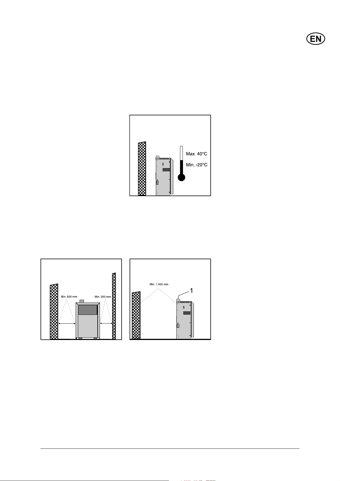
3 Installation 3.1 Temperature conditions ................................................................7
3.2 Condition of distance ....................................................................7
3.3 Foundation / level ling ..................................................................7
3.4 Water connection ..........................................................................8
3.5 Mains power connection ...............................................................8
3.6 Mounting of wash boom ...............................................................9
3.7 Venting of h.p. pump, fuel pump and detergent pumps ..............10
3.8 Connecting to external fuel supply .............................................12
3.9 OPTIONAL: Water softener, drain hose......................................13
4 Operation 4.1 Setting up the AUTO BOOSTER ................................................14
4.1.1 Coin operation / free operation ........................................14
4.1.2 Coin selector settings ......................................................14
4.1.3 Teaching the coin selector to accept a token ...................16
4.1.4 Setting coin value on timer ..............................................17
4.1.5 Maintenance of coin selector ...........................................19
4.1.6 Programs and program selector ......................................19
4.1.7 Temperature setting .........................................................20
4.1.8 Detergent A, B and C ......................................................21
4.1.9 OPTIONAL: Water Softener settings ...............................22
4.2 Running the AUTO BOOSTER ...................................................23
4.2.1 Starting up .......................................................................23
4.2.2 Stopping the AUTO BOOSTER .......................................25
4.2.3 Programs .........................................................................26
4.2.4 Foam brush, mounting & dismounting .............................29
4.2.5 Circulation frost protection ...............................................30
4.2.6 Functional diagrams ........................................................30
5 Maintenance .........................................................................................32
5.1 Coin selector ..............................................................................33
5.2 Hour counters .............................................................................33
5.2 Oil .........................................................................................33
5.3 Water fi lter ..................................................................................34
5.4 Cleaning of high-pressure nozzle ...............................................34
5.5 Fuel fi lter ....................................................................................34
5.6 Disposable waste .......................................................................35
6 Trouble Shooting 6.1 General trouble shooting ............................................................36
6.2 Error messages .........................................................................37
7 Technical Data .........................................................................................38
8 Warranty .........................................................................................39
9 EC Declaration of Conformity .........................................................................................39
3
Page 4
1 Safety Precautions and Warnings
Symbols used to mark instructions
Only let instructed people operate the machine.
General
When using the high-pressure
hot water washer all existing
national regulations must be
observed. Beyond the instruction manual and the current
national legal regulations for
prevention of accidents, also
the approved rules for safe
working must be observed.
Any method of use endangering
the safety of persons or equipment is forbidden.
Before use
Before starting up your highpressure hot water washer
check that it is in a regular
condition. Electric plugs and
couplings must be watertight.
Check the electric cables at
regular intervals for damage
and wear. Only use the high-
Before starting up
your high-pressure
washer for the fi rst
time, this instruc-
tion manual must
be read through carefully. Save
the instructions for later use.
Safety instructions marked with
this symbol must
be observed to
prevent danger to persons.
pressure hot water washer if the
electric cable is all right (damaged electric cables can cause
electric shock!)
Important instructions
Connection to public drinking
water supply must be performed in accordance with the
applicable regulations in your
country.
IMPORTANT: Only use water
without impurities!
Before each use of your highpressure hot water washer
check the most important visual
parts.
High-pressure jets can be dangerous if misused. Never direct
the water jet towards people,
pets, electric wiring, or the machine itself.
Spray handle and lance are affected by a thrust during operation - therefore always hold the
spray lance fi rmly with both
hands.
This symbol is
used to mark
safety instructions that must
be observed to
prevent damage
to the machine and its performance.
This symbol
indicates tips
and instructions
to simplify work
and to ensure a safe operation.
Never try to clean clothes or
footwear on yourself or other
persons.
Operator and anyone in immediate vicinity of the site of cleaning should take action to protect
himself from being struck by
debris dislodged during operation.
Check that cleaning will not
result in dangerous substances
(e.g. asbestos, oil) being
washed off the object to be
cleaned and harming the environment.
Do not clean sensitive surfaces
made of rubber, fabrics or the
like with the zero nozzle. With
the fl at jet nozzle keep a distance of at least 15 cm to the
surface to be cleaned.
Never let children operate the
machine.
Do not use the machine if the
electric cable or the high-pressure hose are damaged.
4
Page 5
Do not cover the machine during operation or use it in a room
without adequate ventilation !
If any of the machines overload protection devices trips
(machine stops unintended),
release the trigger of the spray
handle. Lock the spray handle
with locking device and turn
the start/stop switch to position
„OFF“.
Refer to section “6 Trouble
Shooting”.
Never start the cleaner without
water supply. Even a short water defi ciency can damage the
sleeves of the pump.
Operation
Avoid damage to the electric
cables such as squeezing, pulling, knots etc. and keep them
away from sharp or hot objects.
Avoid damage to the high-pressure hose such as running over
by vehicles, squeezing, pulling,
knots/kinks etc. and keep it
away from oil and sharp or hot
objects, as such may cause the
hose to burst.
The cleaner can be used in
zones classifi ed as ZONE 2.
Important! Never use the
machine in an environment
where there could be a danger
of explosion (according to EN-
50014).
Important! When the system
has been in operation and
thereafter stopped, there might
still be a working pressure in
the pipeline and high-pressure
hoses. Therefore you should
pay special attention to the following:
• Never dismount the highpressure hose from the
machine during operation.
Disconnect the machine and
relieve the high-pressure
hose of pressure prior to
dismounting.
• Never dismount the highpressure hose from the
outlet point before it has
been securely closed and
the high-pressure hose has
been relieved of pressure.
• Prior to any service interference in the machine it
should be disconnected and
the system relieved of pressure by activating the trigger
of the spray handle.
Repair and Maintenance
Only carry through the maintenance operations described in
the operating instructions. Only
use original Nilfi sk-ALTO spare
parts.
Do NOT make any technical
modifi cations to the high-pressure hot water washer.
Warning! High-pressure hoses,
nozzles and couplings are
important for the safety when
operating the machine. Only
use the high-pressure hoses,
nozzles and couplings prescribed by Nilfi sk-ALTO!
For major repairs, please contact your nearest Nilfi sk-ALTO
service organisation.
Mains power connection
This product is intended for
stationary installation only
and is supplied without a
power cord! Only let an authorized electrician connect
the machine to the mains
supply !
The following points must be
observed:
• Check that the voltage
stated on the data plate
corresponds to your mains
voltage.
• Make sure that the power
cord contains the right
number of wires (including
ground wire) and that each
wire has the right dimensions to carry the load (amperage) stated on the data
plate of the machine.
• Make sure that the installation (cables, connection
points and fuses) is correctly
dimensioned for the load of
the machine - refer to the
data plate of the machine.
If not required by local legis
lation, we strongly recommend you to connect the machine to a power source with
a Residual Current Device
(RCD) which will disconnect
the power supply if the leakage current exceeds 30 mA
for 20 milli seconds !
See section “3.5 Mains power
connection” for further instruc-
tions.
Only let a qualifi ed electrician
maintain the electric installation.
Safety Devices
Safety Valve
The pressure side of the highpressure pump is fi tted with a
safety valve. This valve leads
the water back to the suction
side of the pump when the
spray handle is closed or if a
nozzle is blocked.
The safety valve is adjusted
and sealed by the producer.
THIS ADJUSTMENT MUST
NOT BE CHANGED !
Machine protection
The machine features an overcurrent protection and built-in
thermal protection of the motor.
In the event of increased power
consumption (maloperation)
and in the event of excessive
5
Page 6

motor temperature (obstructed
ventilation etc.), the entire
machine will automatically be
disconnected from the mains
supply.
Short circuit protection
The machine is equipped with
a short-circuit protection. In the
event of short-circuits in the
machine, the protective device
will disconnect the entire machine from the mains supply.
2 Description
2.1 Application This high-pressure hot water
washer has been developed
for stationary installation and
self service operation within car
washing
Section 4 describes how to use
the high-pressure hot water
washer.
2.2 Operation elements See foldout at the end of these
operating instructions.
Only use the high-pressure
hot water washer for purposes
described in this manual.
The safety precautions must be
observed to prevent damage
to the machine, the surface to
be cleaned or severe personal
injuries.
1 Wash boom / high pressure
hose
2 Main switch
3 Program selector switch
4 Water inlet (only machines
with optional water softening
unit)
5 Thermostat (temperature
adjustment)
6 Electric box
7 Water tank
8 Detergent container
9 Fuel container
10 Pressure gauge
11 Water softening unit (option)
12 Display (hour counters, error
messages)
13 Brush holder
14 Lance holder
15 Data plate
16 Lifting device
17 Coin selector
18 Assembly box, mains cable
19 "Free operation" switch
20 Heating element, frost pro-
tection
21 Tap (option)
22 No Scale
23 Adjustment of detergent
concentration
6
Page 7
3 Installation
3.1 Temperature conditions The hose, gun and lance are
3.2 Condition of distance In consideration of the cooling
The machine has been constructed for outdoor placement.
The min. ambient temperature
for the machine is –20°C and
the maximum ambient temperature is 40°C.
system of the machine and the
accessibility of service, there
must be free wall space on both
sides of the machine. To the
frost protected to -20°C provided by circulation of preheated
water through the system. The
lance must be placed in the
lance holder (14 ) after use in
order to circulate the water in
periods with frosty weather.
The machine features a fan
heater automatically starting up
when the temperature inside
the machine gets too low.
The adjustment of the thermal
sensor is effected in the electric
box. On delivery the adjustment
has been set at 5°C. This setting must not be lowered.
right 200 mm at a minimum, to
the left 500 mm at a minimum
and behind 300 mm.
The distance from the chimney
outlet to infl ammable material
must be 1,000 mm. This distance can be reduced to 300
mm by mounting a diverter. You
will fi nd diverter and instructions for mounting in the front
door.
3.3 Foundation / levelling Place the machine on a plane
fl oor.
Bolt the machine to the foundation through the 3 holes (Ø12
mm) in the bottom plate. Before
fastening, the machine must be
levelled.
The chimney (1) can be turned
180° by dismounting 4 pcs. M5
screws (under the top plate),
turning the chimney and remounting the screws.
Shape of foundation, see foldout at the end of this manual.
7
Page 8
3.4 Water connection The water connection is made
with a fl exible hose connected
to the water tank (7) of the
machine or to the optionally
mounted water-softening unit
(11).
perature and fl ow rate). If in
doubt, contact your Nilfi sk-ALTO representative. Also ensure
that the water supply hose is
protected against freezing between the outlet and the AUTO
BOOSTER.
The water hose can be lead in
through:
1. The bottom plate
2. The punch-out pieces in the
rear plate
(see foldout at the end of this
manual).
Make sure that the supply hose
is suited for the purpose (tem-
The connection can be made to
a public drinking water supply
network or a private water supply. Water quality: particle size
<50 μ. A shut-off cock should
be mounted on the water supply network in the immediate
vicinity of the machine. Make
sure that the water supply is
within the following specifi cations and that the water does
not contain particles such as
fl oating sand.
Min. water inlet pressure: 1 bar
(at the required fl ow rate of the
machine - see data plate.
Max. water pressure: 10 bar
Max. water inlet temp.: 30°C.
(Machine with optional water
softening unit - max. water
pressure: 6 bar)
All AUTO BOOSTER feature a
water break tank, and no further
protection against back-fl owing
water into the supply network is
required. The machine complies
with EN 1717.
If there is a risk of fl oating sand
or other impurities in the inlet
water, a sand fi lter (50 micron)
should be mounted between the
supply outlet and the internal
fi lter of the machine.
3.5 Mains power connection
8
CAUTION! An
authorized electrician must perform
the electrical
connection of the machine to
the main power supply. Refer to
section “1 Safety precautions
and warnings”.
The following precautions must
be observed:
• Make sure that the supply
cable is of the correct dimension (see voltage and load on
the data plate of the machine
(15)) and that it is suitable for
the specifi c environment.
Page 9
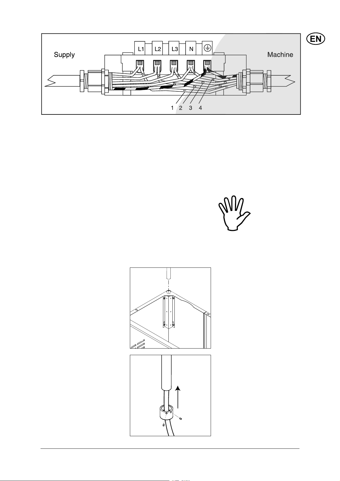
Assembly box, mains cable (see pos. 18 on foldout at the end of this manual)
The electric cable can be lead
in through:
1. The bottom plate
2. The punch-out pieces in the
rear plate and through the relief ring into the junction box.
(see foldout at the end of this
manual).
• Connect the phase cords of
the supply cable to the connection terminals L1, L2 and
L3. Connect the zero cord to
3.6 Mounting of wash boom Your AUTO BOOSTER comes
N. For single phase machines use L1 and N to connect
phase and zero cords.
• Connect protective earth wire
to the earthing terminal.
• Check and measure the
protective earth connection
according to legislation.
• Connect the other end of the
cable to an approved socket
of a correct dimensioned
main supply.
Make sure that the cable is
properly guided and relieved
between the fi xed installation
and the machine and that the
cable is without any damage to
the insulation.
Also see notes in section
“1 Safety precautions and
warnings”!
Note: Beware
that the electric
cables of the
machine are not
mixed up. The
wires 1, 2, 3, 4
MUST keep the
illustrated positions.
with all high-pressure connections already made – the highpressure hose is led through
the wash boom with connection
to high pressure pump in one
end and spray handle in the
other.
Mount the wash boom (1) into
the hole/bracket in the top of
the AUTO BOOSTER (left side).
Slowly pull the high-pressure
hose out of the wash boom until
the full length is achieved.
Place the locking ring of the
boom in position and lock it by
tightening the two screws.
The wash boom and hose /
spray handle / lance are now
ready for use.
9
Page 10
/
+
%
3
#
-)4
35"
)3()
3.7 Venting of HP-pump,
fuel pump and detergent
pumps
When the AUTO BOOSTER is properly connected to supply water,
electrical installation and the wash boom / high-pressure hose
are fi tted, the AUTO BOOSTER’s hydraulic and fuel lines must be
vented before it is operational.
● Set thermostat (5) to 40 ºC.
● Fill fuel into the fuel container (9).
● Fill No Scale into the container (22).
● Fill detergent containers (8) with the appropriate detergents (see
section 4.1.8).
#
● Open electric box (6) and set all Cold / Hot switches (S1, S2, S3,
S4, S5) to “Hot” (= ON).
● Enable running without payment (19).
● Close electric box.
10
1. Turn the main switch, (2) to position “ON”.
!
"
$#
).054
Page 11
2. Activate the trigger of the spray handle on high-pressure hose,
and turn the program selector switch (3) to program 1. The AUTO
BOOSTER will start.
3. Let the water run until all air has escaped from the pump (even
water fl ow), and check that the burner is running and detergent A
is mixed into the water stream (foaming). Release the trigger of
the spray handle and wait a few seconds until the HP pump stops
(note that the burner will continue running until the temperature
in the break tank reaches 40 ºC.
4. Turn the Program selector to program 2 and activate the spray
handle again. Observe that waterfl ow decreases (pressure drop)
and that detergent B is mixed into the water stream. Run for 30
seconds to fully vent chemical pump B then close spray handle.
5. Turn the Program selector to program 4 and repeat step 5.
Chemical pump C is now vented.
6. Stop the AUTO BOOSTER by turning the Selector switch to position STOP.
The AUTO BOOSTER is now vented and ready for use.
11
Page 12
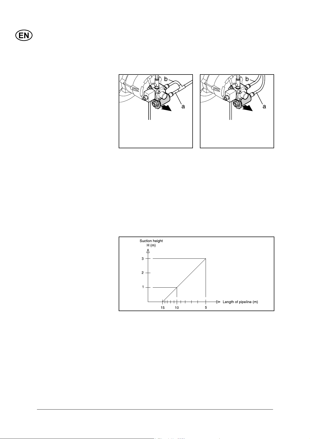
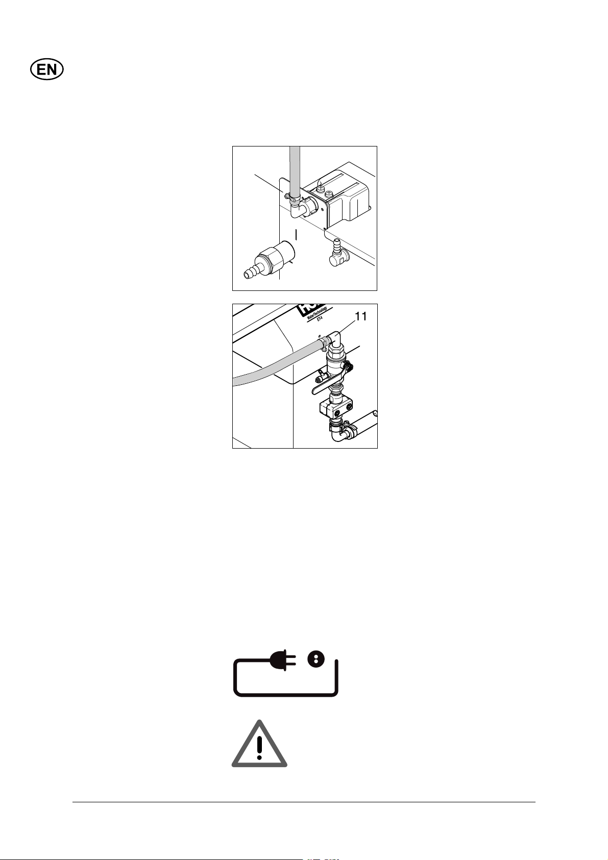
3.8 Connecting to external
fuel supply
The AUTO BOOSTER can be connected to an external fuel supply.
As a standard, the machine is supplied with a 33 l container.
You can choose between “one” and “two” -string connection, where
“one”-string only has one supply hose (a) and “two”-string has an
additional return hose (b) - see fi gure.
Please observe that in some countries only the “one” string system
is approved.
The fuel hose for the external fuel supply can be lead-in:
1. Through the bottom plate to the oil pump.
2. Through the punch-out pieces in the rear plate to the oil pump.
See foldout at the end of this manual.
Please observe the following restrictions to fuel line.
12
Page 13
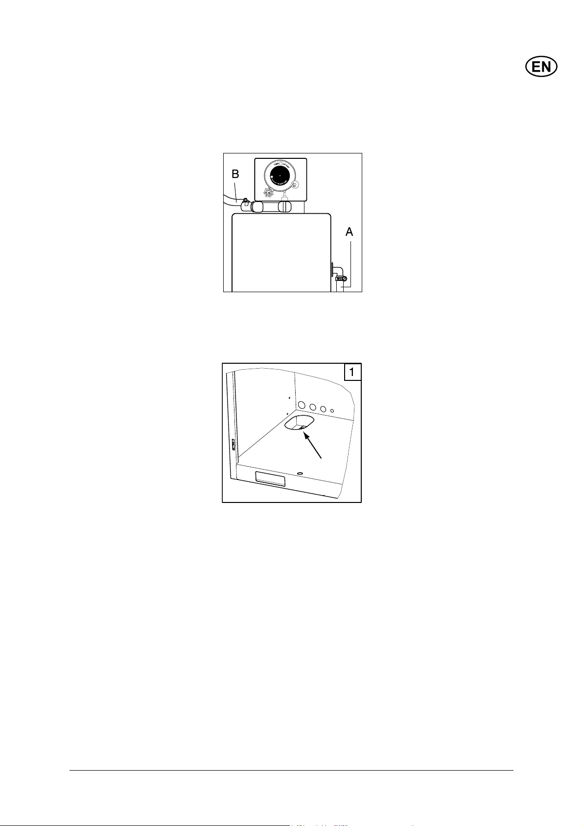
3.9 OPTIONAL: water
softener - drain hose
Your AUTO BOOSTER may be equipped with the optional water
softener of the type that regenerates automatically - depending on
the water hardness and the water consumption.
The water softener has two drain hoses - one at each side. One
is for overfl ow (A), the other is used during regeneration (B). Both
hoses are transparent with woven reinforcement.
Make sure that both drain hoses are guided through the bottom
chassis of the AUTO BOOSTER and connected to an appropriate
sewer or drainage, capable of sinking approximately 55 liters of
salty water during regeneration.
Pour fi lter-salt recommended by Nilfi sk-ALTO into the water softener container - it will accept maximum 25 kg.
Your water softener is now ready for use. Please refer to section
4.1.9 for setting of the automatic regeneration timing.
13
Page 14

4 Operation
4.1 Setting up the AUTO
BOOSTER
The AUTO BOOSTER is designed as a user-friendly, self-service product, where the user
can buy operation time to wash
his vehicle.
Several features are adjustable
by the owner, in order to provide a certain offering for a
certain price.
● The owner must decide which
payment to accept – coins
of national currency and/or
tokens,
● and how long washing time
should be assigned to specifi c
coins / tokens.
The AUTO BOOSTER provides
5 different program steps with
the possibility to add 3 different
detergents.
● The owner must decide if
the individual program steps
should run with hot (internally
heated, up to 60ºC) or cold
water.
● Also the detergent concentration of the 3 detergents
must be determined within
the range of Nilfi sk-ALTO
recommendations.
If the AUTO BOOSTER is optionally equipped with water softening unit (11), the owner must
decide, at which times (outside
of normal operation hours) the
regeneration of the softening
unit should take place.
4.1.1 Coin operation / free
operation
4.1.2 Coin selector
settings
Normally the AUTO BOOSTER
can only be started and used
when appropriate payment is
done.
By means of a “Free operation”
switch (19), the owner can decide to bypass or to disconnect
the payment system.
!!NOTE – The
circulation frost
protection will
NOT be operative
during Free Use –
payment cancelled!!
The coin selector (17) in the
AUTO BOOSTER is either.
● European type, accepts €, £
and CHF and tokens
or
14
● Scandinavian type, accepts
NOK, DKK, SEK and tokens.
Page 15

European label Scandinavian label
The type is shown at the label
on the side of the coin selector.
To ease access to the label and
coin selector switches, the coin
selector can be unclipped from
the front panel.
Upon reception of the AUTO
BOOSTER all the coins of the
currencies listed on the label
will be accepted.
European type:
● Blocking switch 7 = “ON”,
blocks all € - coins
● Blocking switch 9 = “ON”,
blocks all CHF-coins
● Blocking switch 10 = “ON”,
blocks all £ - coins
Scandinavian type:
● Blocking switch 7 = “ON”,
blocks all NOK - coins
● Blocking switch 9 = “ON”,
blocks all DKK-coins
● Blocking switch 10 = “ON”,
blocks all SEK – coins
Example 1: An owner in
Germany wants the AUTO
BOOSTER coin selector to accept only € - coins.
● Blocking switch 7 must be in
“OFF” position to accept €
coins (0.50€ - 1.00€ - 2.00€).
The owner can “block” coins
of the currencies not valid in
his country with the “blocking
switches” on the side of the coin
selector .
● Blocking switches 9 and 10
must be “ON” to disable CHF
and £ coins.
Example 2: In Denmark, only
Danish Kroner, DKK, should be
accepted. On the Scandinavian
coin selector set switches as
follows:
● Blocking switch 9 must be in
“OFF” position to accept DKK
coins (5 DKK – 10 DKK – 20
DKK)
Blocking switches 7 and 10
must be “ON” to disable NOK
coins and SEK coins.
On both coin selectors the
“Blocking switches 1,2,3,4,5,6”
can further be used to disable
coins of wide tolerances. For
normal operation they should all
be left in the “OFF” – position.
15
Page 16

The “Blocking switches
11,12,13,14,15,16” are all used
only to teach the coin selector to recognize user defi ned
tokens. Leave these in “OFF”position for now.
The Switch 8 is designated
“Teach switch”. Leave this
“OFF” for normal operation.
4.1.3 Teaching the coin
selector to accept a
token
Both the European and the
Scandinavian coin selector can
be “taught” to recognize and
accept a user defi ned token.
The token can be assigned one
of six values by choosing one
of six “Teach Channels”, represented by the blocking switches
11,12,13,14,15 and 16 (see
4.1.4)
Teaching is done by setting the
coin selector to Teach Mode,
selecting a “Teach Channel”
and then entering a minimum of
10 tokens through the coin slot.
The procedure is similar for the
European and the Scandinavian coin selector, and can be
performed with the coin selector
in the machine.
Before beginning teaching
● Set AUTO BOOSTERr’s main
switch (2) to OFF.
● Set blocking switches
11,12,13,14,15,16 on coin
selector to OFF.
● Set teach switch 8 on coin
selector to OFF.
● Set AUTO BOOSTER’s main
switch (2) back to ON.
● On coin selector set Teach
Switch 8 ON to enter teach
mode.
● On coin selector set blocking
switch 13 – „TK13 C“ – to ON.
Teaching
● Enter Token min. 10 times
(use several tokens/coins to
have a better acceptance).
● On coin selector set blocking
switch 13 back to OFF position. One single click from
coin selector indicates that
the Token is accepted. (other
indications: Token not accepted – less than 10 entries
or invalid tokens - try again).
● Switch pin 8 back to OFF
position.
The coin selector is now tought
to recognize and accept the
Token as valid payment, and
the value assigned to the Token
depends on the chosen Teach
Channel (see 4.1.4).
Tokens and national coins can
be used simultaneously, when
their blocking switches are OFF.
16
Entering Teach Mode (in this
example Teach Channel 13 is
chosen)
Page 17

4.1.4 Setting coin value on
&
-)435")3()
!
"
4RANSFORMER
0ER
3IKR
4YPE%"3)
0RIM
3EK
%LEKTRODYN
6
6
(Z
!
/.
/.
!
&
!
&
4
./
./
#
4
!"
,
4
4
,
,
+
4
4
#
!"
4
./
+
,
,
,
./
&
!"
4IMERPRINT
!
3
333333
/RANGE/RANGE
/RANGE'RÍ
timer
0RIM
3EK
4YPE%"3)
3IKR
0ER
(Z
%LEKTRODYN
4RANSFORMER
4
,
,
!"
#
4
4
,
,
4
./
,
,
./
!"
+
+
#
./
./
4
4
4
-)435")3()
!
&
333333
!
&
/RANGE'RÍ
/RANGE/RANGE
Locate the Timer board inside
the AUTO BOOSTER’s electric
box.
3
!"
&
&
/.
/.
4IMERPRINT
!
On the “Minimum Price” switches choose the minimum price to be
paid for the AUTO BOOSTER to operate. On the “Time Setting”
switches choose the time value you want to assign to the minimum
price.
Minimum price setting:
Use pins to set minimum
price to activate machine. See coin table and
example following.
Interface to power supply and
AUTO BOOSTER control.
Time setting:
Use pins to set time value
of coin/token. See coin table and example following.
Factory programming
interface.
Interface and power supply
to coiner.
17
Page 18

See below tables for European and Scandinavian coin selectors:
EMP 8.000.00 v5/E/I/T Timer T220
Settings for EU Coin Selector
Coin type Currency Pulses
SW no.
0,50 EUR 1
1,00 EUR 2
2,00 EUR 4
1,00 CHF 2 Time setting (sec. / minimum price)
2,00 CHF 4
5,00 CHF 10
0,50 GBP 1
1,00 GBP 2
2,00 GBP 4
TK11 A 2 1 €, CHF, £
TK12 B 4 2 €, CHF, £
TK13 C 6 3 €, CHF, £
TK14 D 8 4 €, CHF, £
TK15 E 10 5 €, CHF, £
TK16 F 12 6 €, CHF, £
Price
SW no.
Sec's
Price Setting: Select minimum price (basis for time setting)
Minimum price switch
1234 567 8
0,50 1,00 2,00 4,00 8,00 16,00 32,00 64,00
Select time value in Sec's for selected "minimum price"
1234 567 8
10 20 40 80 160 320 640 1280
Example of setting in €-country:
Owner wants 2,5 € to be inserted before machine can start:
Flip SW1 & SW3 (0,50 € + 2,00 €) on "Minimum price switch".
Owner wants to assign 10 minutes to the minimum price 2,5 €:
Flip SW3, SW4, SW5 & SW6 (40+80+160+320=600 sec's = 10 minutes)
on "Time Setting Switch".
All other coin values will be adjusted proportionally by the timer - i.e. 1€
will be 240 sec's, or 4 minutes.
Owner also wants to use a token with an assigned value of 3 €:
As 1 € corresponds to 2 impulses, 3 € equals 6 impulses - so owner
teaches "TK13C" to recognize the token (see how in sect. 4.1.3).
Minimum price setting:
Use pins to set minimum price
Time setting:
Use pins to set time value of
minimum price.
18
Page 19

EMP 8.000.00 v5/E/I/T Timer T220
Settings for Scandinavian
Coin Selector
Coin type Currency Pulses
SW no.
5,00 NOK 1
10,00 NOK 2
20,00 NOK 4
5,00 DKK 1 Time setting (sec. / minimum price)
10,00 DKK 2
20,00 DKK 4
5,00 SEK 1
10,00 SEK 2
TK11 A 1 5
TK12 B 2 10
TK13 C 4 20
TK14 D 8 40
TK15 E 10 50
TK16 F 12 60
Price
SW no.
Sec's
DKK,NOK,SEK
DKK,NOK,SEK
DKK,NOK,SEK
DKK,NOK,SEK
DKK,NOK,SEK
DKK,NOK,SEK
Price Setting: Select minimum price (basis for time setting)
Minimum price switch
1234 567 8
0,50 1,00 2,00 4,00 8,00 16,00 32,00 64,00
Select time value in Sec's for selected "minimum price"
1234 567 8
10 20 40 80 160 320 640 1280
Example of setting in Norway:
Owner wants 5 NOK to be inserted before machine can start:
Flip SW2 & SW4 (1,00 NOK + 4,00 NOK on "Minimum price switch".
Owner wants to assign 2 minutes 30 sec's to the minimum price of
5,00 NOK.
Flip SW1, SW2, SW3 & SW4 (10+20+40+80 = 150 sec's = 2 min. 30
sec's) on "Time Setting Switch".
All other coin values will be adjusted proportionally by the timer - i.e. 10
NOK will be 300 sec's, or 5 minutes.
Owner also wants to use a token with an assigned value of 50 NOK:
As 5 NOK corresponds to 1 impulse, 50 NOK equals 10 impulses - so
owner teaches "TK15E" to recognize the token (see how in sect. 4.1.3).
4.1.5 Maintenance
4.1.6 Programs and
Program Selector
The EMP 800 is an extraordinarily robust coin selector and
operates relatively maintenance
free. However, it should be
cleaned at regular intervals
especially if it is operating in an
environment with high levels
of dust, smoke or nicotine. The
cleaning intervals are of course
dependent on the level of air
borne contaminants.
Modest use with minimum
contaminant levels indicates
the need to clean the top of the
coin path once a year. Open
the coin path door and wipe the
exposed surfaces with an alcohol moistened cloth. The light
sensors may be cleaned with a
soft brush or air spray duster.
When payment in done, the
user can choose freely between
the AUTO BOOSTER's washing programs within the time
paid for.
Indication of inserted payment followed by remaining time counting down when
program switch is not at STOP
19
Page 20

4 Programs without water softener (hard water)
Program Description Flow rate Temp. Detergent Water Memo
1 High pressure cleaning 100% Hot A (Super Plus / Auto Active) Hard
2 Foam brush 50% Hot B (Super Plus / Auto Active) Hard
3 Clear rinses 100% Cold Hard
4 Gloss rinses 50% Cold C (Auto Dry) Hard
5 Gloss rinses 100% Cold Hard Program blanked out
with label
5 Programs with water softener (soft water)
Program Description Flow rate Temp. Detergent Water Memo
1 High pressure cleaning 100% Hot A (Super Plus / Auto Active) Soft Detergent (AA) (insect
2 Foam brush 50% Hot B (Super Plus / Auto Active) Soft
3 Clear rinses 100% Cold Soft
4 Gloss rinses 50% C or H C (Active Wax) Soft
5 Gloss rinses 100% Cold Soft
Above examples are from Germany on how the AUTO BOOSTER should work with only 4 program steps on hard water and 5
program steps on soft water. If wanted, hot or cold water can be chosen freely on any of the programs (selector inside electric
box) and other detergents may be used.
-solver ex. 2005)
With soft water (<10 ºdH) we
recommend that you use 5 programs with the recommended
Nilfi sk-ALTO detergents.
with the recommended Nilfi skALTO detergents. Though for
best cleaning result we recommend to install the “Water softening” option when choosing 5
For water hardness’s between
programs.
10 ºdh and 20 ºdH you may
choose either 4 or 5 programs
If you choose to run with 4
program steps, we recommend
that you exchange the “Active
Wax” detergent with the “Auto
Dry” in program 4. Program
step 5 should not be used.
Use the extra "STOP" sticker (in
the plastic bag with coin labels)
to blank program 5 on the front
label.
If your water is hard (> 20 ºdH)
you must install a water soften-
ing unit (11).
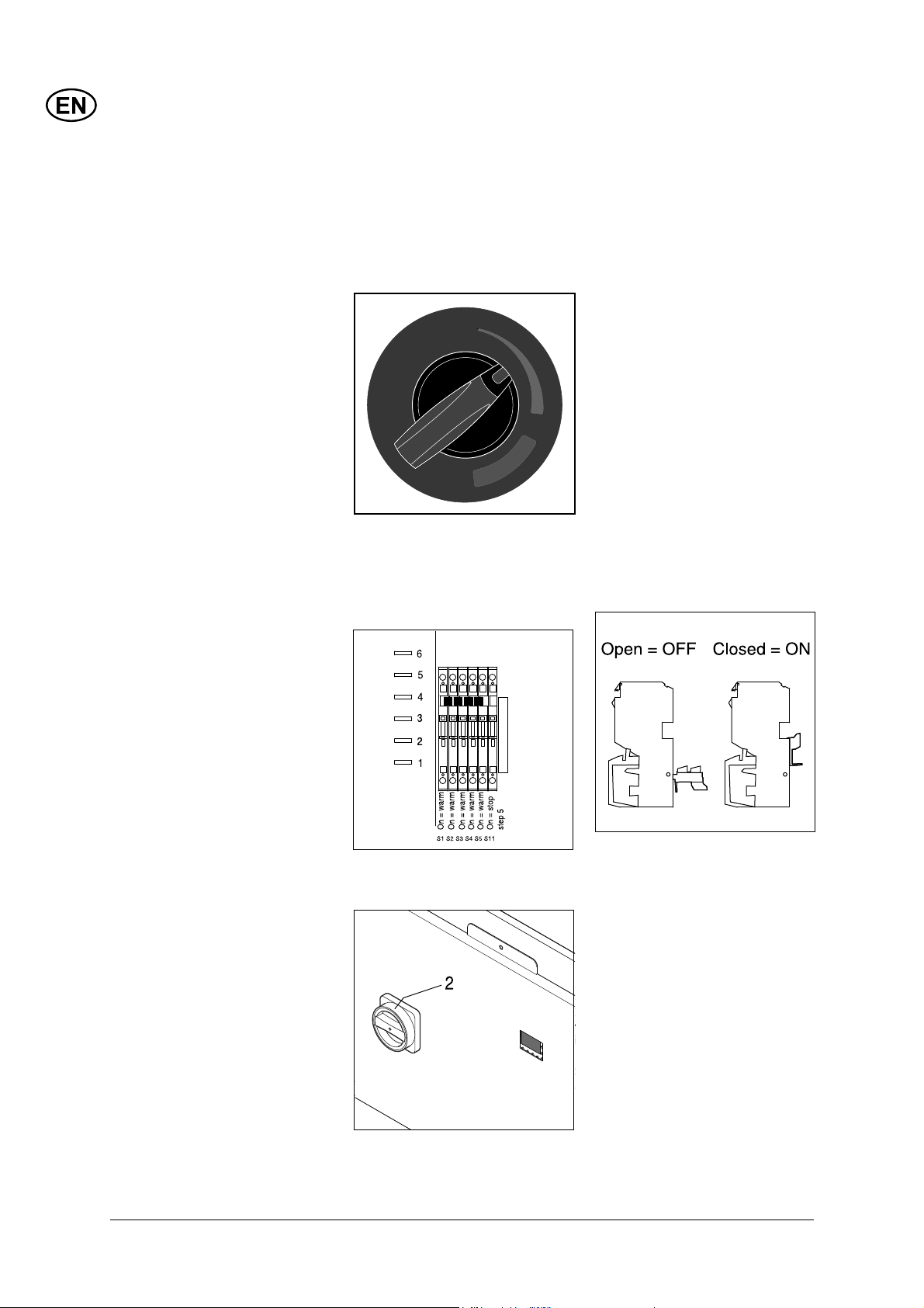
4.1.7 Temperature setting The overall setting of the hot
water temperature, is done on
the Thermostat (5) (max 60º C).
#
Recommended temperature for
car cleaning: 40°C.
20
Page 21

Each program step can be
assigned either cold or hot
(thermostat temperature) water,
which is done on the 5 “Hot/
Cold” switches S1, S2, S3, S4,
S5 (one pr. program) located
inside the electric box.
An Open switch assigns cold
water.
A closed switch assigns hot
water.
4.1.8 Detergents A, B and C
Nilfi sk-ALTO's suggestions for detergent addition per program step:
4 Programs, water hardness > 20° dH
Program Description Flow rate Temp. Detergent Water
1 High pressure cleaning 100% Hot A (Super Plus / Auto Active) Hard
2 Foam brush 50% Hot B (Super Plus / Auto Active) Hard
3 Clear rinses 100% Cold Hard
4 Gloss rinses 50% Cold C (Auto Dry) Hard
5 Gloss rinses 100% Cold Hard
5 Programs, water hardness < 10° dH or water softener installed
Program Description Flow rate Temp. Detergent Water
1 High pressure cleaning 100% Hot A (Super Plus / Auto Active) Soft
2 Foam brush 50% Hot B (Super Plus / Auto Active) Soft
3 Clear rinses 100% Cold Soft
4 Gloss rinses 50% C or H C (Active Wax) Soft
5 Gloss rinses 100% Cold Soft
The concentration of detergent
I
I
I
I
I
I
I
I
I
I
I
I
I
+
I
I
I
I
I
I
I
I
I
I
I
I
I
+
can be adjusted on the indi-
vidual detergent pumps. The
concentration of detergent in
the water jet can be adjusted
from 0 - 0.8 %.
21
Page 22

4.1.9 OPTIONAL: water
softener settings
The water softening unit (11) contains an electrical/mechanical
timer using a seven-days gear wheel for setting of the time of regeneration.
Set the timer as follows:
1. Dismount the plastic cover of the unit and the cover of the timer.
2. Turn the dial (A) by hand until the required regeneration time
appears in the window (B). Choose a time when the machine is
not in use.
3. Turn the timer knob (K) anti-clockwise until the present hour ap-
pears (L).
4. With all the pins (E) pulled out, turn the wheel (D) until day "1" is
opposite the day indicator (C). Then push in the pins of the days
on which the regeneration is required.
5. Turn on the water on the vacuum valve. Now the brine tank will
be fi lled with water. The valve will automatically close when the
correct volume has been reached.
6. Slowly turn the timer knob anti-clockwise until the knot (F)
pushes the actuator down to open the discharge piston (G).
Depending on the placement of the pins (E) this may require a
few attempts.
7. Let the valve suck water from the brine tank until the brine valve
closes.
8. Fill salt tablets into the brine tank.
9. Slowly turn the timer knob (K) anti-clockwise until the actuator
has released. Now the valve is back in operating position.
10. Repeat items 3 + 4.
22
Note: If the mains voltage disappears, the time must be reset.
Example: The dial (A) has been set at 23 (B). Pins (E) 1, 3, 5, 6, 7
are pressed in (day 1 = Monday).
The regeneration will be effected on Monday, Wednesday, Friday,
Saturday and Sunday at 23 o'clock.
Calculation of time between regenerations can be made as follows:
1. Check the hardness (°dH) of the water.
2. Determine an approximate water consumption (Q) per day.
3. 24,000/Q x °dH = Tmax.
Page 23

/
+
%
3
#
-)4
3
5"
)
3
()
Example:
Water hardness: 5°dH
Water consumption per day: 2,250 l/day.
Tmax = 24,000/2,250x5 = 2.13
This means that the regeneration must be effected every other day.
Specifi cations:
Capacity at 1°dH: 24,000 l
Salt consumption per regeneration: 1.5 kg
Container for salt: 25 kg
Time of regeneration: 30 min.
Water consumption per regeneration: 55 l
Units for water hardness:
1 °dH - German std.
= 0.56 Fd - French std.
= 0.80 Ed - English std.
4.2 Running the AUTO
BOOSTER
4.2.1 Starting up
Prior to setting the AUTO BOOSTER into operation the entire machine should be properly vented, (section 3.7), and the settings of
the paying system should be carried out (section 4.1.1 to 4.1.4).
1.Turn the main switch on the front of the electric box to position
“ON”.
!
"
$#).054
2. Observe that the display next to the coin input is illuminated and
shows “00:00”.
23
Page 24

3. Close the door of the AUTO BOOSTER, and lock the two keylocks.
"
"
!
B
"
!
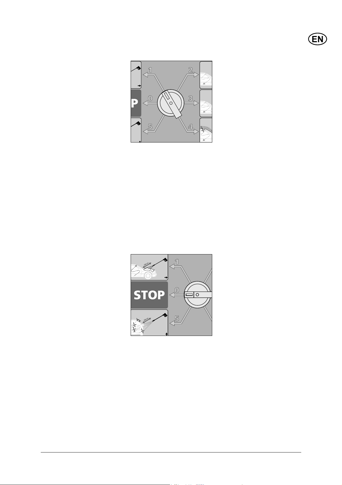
4. Position the program selector switch (3) in position “STOP”.
5. The AUTO BOOSTER is now operative.
By inserting valid coins or tokens through the coin inlet, the display
will show the payment, summing up as more coins are inserted.
!! NOTE: The preset “minimum payment” (section
4.1.4) must be inserted before the AUTO BOOSTER
is allowed to start !!
When the program switch is turned from STOP to one of the
program steps, the AUTO BOOSTER will start and the display will
change to show the prepaid washing time in “minutes : seconds” –
counting down. The customer is free to choose between the programs during pay-time.
24
Page 25

Once the count-down has begun, it will continue towards zero,
no matter if the program selector switch is again placed in STOP
position.
Further coins can be inserted during the count-down, and will be
refl ected by adding the time-value of the coin to the value in the
display.
4.2.2 Stopping the
AUTO BOOSTER
!! NOTE: In case of emergency turn the program
selector switch (3) to STOP, or push the optional
“Emergency Switch” !!
When pay time runs out (display at 00:00) the AUTO BOOSTER
will automatically stop and relieve pressure from the hose/spray
handle, no matter where the program selector switch is positioned.
If working is terminated for more than 30 seconds during pay-time
(closed handle), the AUTO BOOSTER will enter standby mode,
and the HP pump will stop. Working can be resumed, as long as
pay time has not expired.
!! NOTE: Do not disconnect the AUTO BOOSTER
from main power supply, neither by turning AUTO
BOOSTERs main switch to position “OFF”, nor by
interrupting external installation switches as this will
leave the AUTO BOOSTERs automatic frost protection device inoperative, and the optional water
softening device will need new setting of regeneration clock. !!
25
Page 26

4.2.3 Programs
Running with soft water (< 15° dH) or with the optional “Water
softening device” we recommend the following wash sequence for a medium size car:
Program 1 - (use approx. 3
minutes).
- Hot (or Cold), High pressure
rinse with detergent “A”.
Move the lance along the car in
a “Z” pattern, down-up, keeping
the nozzle approx. 20 cm from
the bodywork, rinsing away bigger particles as mud, salt, sand
and insects.
Program 2 - (use approx. 6
minutes).
- Hot (or Cold), Low pressure
rinse with foam brush and
detergent “B”.
Attach the foam brush to the
bayonet coupling of the lance
(see 4.2.4), and brush-wash the
car, removing traffi c-fi lm and
“sticking objects”.
Program 3 - (use approx. 2
minutes).
- Cold (or Hot) High pressure
fl ushing without detergent.
Remove the foam brush (see
4.2.4.) and fl ush off all soap
remainders.
Program 4 - (use approx. 3
minutes).
- Hot (or Cold) Conservation
with wax, low pressure and
detergent “C”.
Apply wax over entire bodywork, and leave on for approx. 1 minute.
26
Page 27

Program 5 - (use approx. 2
minutes).
- Cold (or Hot) High pressure
fl ushing without detergent.
Flush off remainders of wax.
STOP
- Always place the Selector
switch in this position when
cleaning is completed.
NOTE: The owner can individually assign hot or cold to each
program step (section 4.1.7).
NOTE: Always
place the lance in
the lance holder,
in order for the
circulation frost
protection system
to work.
Running with hard water (>15° dH) without the optional “Water
softening device”, the wax-conservation will not be of good
quality. Thus we recommend that program step 5 is disconnected and turned into an extra STOP function by closing the
switch S11 (OFF).
The “Active wax” detergent in container “C” must be replaced by
the “Auto Dry” detergent (see sec. 4.1.6), and the wash sequence
for a medium size car will be:
27
Page 28

Program 1 - (use approx. 3
minutes).
- Hot (or Cold), High pressure
rinse with detergent “A”.
Move the lance along the car in
a “Z” pattern, down-up, keeping
the nozzle approx. 20 cm from
the bodywork, rinsing away bigger particles as mud, salt, sand
and insects.
Program 2 - (use approx. 6
minutes).
- Hot (or Cold), Low pressure
rinse with foam brush and
detergent “B”.
Attach the foam brush to the
bayonet coupling of the lance
(see 4.2.4), and brush-wash the
car, removing traffi c-fi lm and
“sticking objects”.
Program 3 - (use approx. 2
minutes).
- Cold (or Hot) High pressure
fl ushing without detergent.
Remove the foam brush (see
4.2.4.) and fl ush-off all soap
remainders.
Program 4 - (use approx. 3
minutes).
- Hot (or Cold) Conservation
with “Auto-Dry”, low pressure
and detergent “C”.
Apply “Auto-dry” over entire
bodywork, and let the water run
off by itself.
28
Page 29

STOP
- Always place the Selector
switch in this position when
cleaning is completed.
4.2.4 Foam brush, mounting
& dismounting
A soft foam brush is available for the AUTO BOOSTER to be used
during program step 2.
On the left-hand side of the AUTO BOOSTER is placed a holder for
storing the soft foam brush when not in use.
The soft foam brush is equipped with a female bayonet coup ling
that will accept the male bayonet coupling on the end of the spray
lance.
Attach the brush to the lance by pushing the brush fully onto the
lance (spring-loaded) and twist, until the bayonet couplings engage.
Remove the brush from the lance by reversing the above process.
29
Page 30

4.2.5 Circulation frost
protection
As standard the AUTO
BOOSTER is equipped with a
circulation device to protect the
hose, the spray handle and the
lance from freezing during periods with frost. Also, an internal, electrical heating element
will prevent the machine itself
from freezing. In order for the
system to operate, the AUTO
BOOSTER must not be disconnected from main electric supply (see note in sec.4.2.1)
A thermostat switch mounted
on the outside of the chassis of
the AUTO BOOSTER switches
ON the circulation frost protection system when the temperature is below the pre-set temperature and no coins have been
inserted in the slot.
Thus a separate pump starts
circulating preheated water
through the hose, spray handle
and lance.
The lance must be placed in
the holder at the left side of the
AUTO BOOSTER in order to
re-circulate the water (see note
in sec. 4.2.3). If the lance is
placed outside the holder, the
water will spill on the ground at
a rate of approximately 1.5 l/
min.
An extra thermostat is located
inside the cabinet of the AUTO
BOOSTER to switch ON the
electrical heating element in
the cabinet, if the inside temperature drops below the pre-set
temperature.
!!NOTE – The
circulation frost
protection will
NOT be operative
during Free Use –
payment cancelled!!
4.2.6 Functional diagrams The following three functional diagrams describes the operation of
the AUTO BOOSTER in cold, hot and frost protection mode.
COLD:
30
Page 31

HOT:
FROST:
31
Page 32

5 Maintenance
To ensure the most optimal maintenance of your auto BOOSTER, you should consider making a “Service Contract” with Nilfi sk-ALTO. In this way your TRUCK BOOSTER will always be ahead of potential
problems.
Though paying attention to a few things will ensure a prolonged and reliable operation of your AUTO
BOOSTER.
Therefore it will be a good idea to follow the schedule of maintenance below. All times are intended as
a guide and the maintenance should be made at more frequent intervals if required.
Day Week Month Year Winter
Fuel Check fuel level. Start machine and check
that the boiler is working. If not, see sec-
tion 3.7.
Detergent Check level in all detergent containers. x
Oil, high pres-
sure pump
Coin collector Empty coin collector. x
Washing
brush
Hose/lance Check hose/lance for wear and leaks.
Nozzle Check spray picture. Clean the nozzle if
Water break
tank
Detergent /
fuel containers
Water softening unit (option)
Water softening unit (option)
Water softening unit (option)
Water fi lter Clean the water fi lter of the water break
Fuel fi lter Replace fuel fi lter (see section 5.6). x
Lance holder Check the lance holder for foreign bodies.
Frost protection
Check oil level. Refi ll if necessary. Send for
a Nilfi sk-ALTO service technician as soon
as possible to have the cause of the oil
consumption established.
Check the washing brush for wear and
impurities. Replace if necessary.
Replace if necessary.
necessary (see section 5.5).
Empty the water break tank and clean it of
impurities.
Empty the containers and clean them
of impurities. Also clean the fi lters in the
detergent containers.
Check the level of salt tablets. If necessary
refi ll with salt tablets above the water level
in the brine tank.
Empty the brine tank and clean it.
Check the setting of the timer. Adjust if
necessary (see section 4.1.7). x
tank (see section 5.4).
If necessary, dismount it by loosening 4
bolts.
Check that the heating unit starts in the
machine and that water is running through
the lance when the temperature drops be-
low 4°C. NOTE: The surface of the heating
unit may be very hot !
x
x
x
x
x
x
x
x
x
x
x
x
32
Page 33

Drain Check the drain of the washing place. x
Outdoor ther-
mostat
Clean the outdoor thermostat at the bot-
tom of the front door with a dry cloth.
x
Locks Lubricate locks with acid-free oil. x
Machine Check machine functions, payment, deter-
gent, hot/warm switch, hose, brush, lance.
x
5.1 Coin selector See section 4.1.5.
5.2 Hour counters Your AUTO BOOSTER features built-in hour counters that keep
track of the number of working hours on your machine.
By turning the program selector switch (3) to position 1, the display will show working hours of pump and boiler and version no. of
software.
+
-
By turning the program selector switch to position 2, the working
hours with various detergents will show.
By turning the program selector switch to position 3, the total number of start-ups of the machine will show.
By turning the program selector switch to position 4, the display will
show the total number of minutes paid for.
The fi gures will only show when no coins have been inserted.
5.3 Oil Your AUTO BOOSTER is equipped with an electronic “oil sensor”,
which monitors the level of lubricant oil in the high-pressure pump. If
the oil level (by malfunction or excessive wear) should drop to a low
level, the pump will stop and the display shows "Pump oil level low".
+
-
Topping up the oil cup of the pump will be possible, but you should
send for a Nilfi sk-ALTO service technician as soon as possible to
disclose the cause of the oil loss.
33
Page 34

PROTECT THE ENVIRONMENT
5.4 Water fi lter To avoid debris entering the water break tank and the high-pres-
Waste oil and oil sludge must be removed as laid down in the
instructions.
sure pump, water fi lters are fi tted at the water inlet of the water
break tank and the pump. Depending on the purity of the water, this
fi lter will have to be cleaned at regular intervals.
The fi lter can be removed by unscrewing the union nut (1).
If the fi lter is clogged up by impurities, the machine will stop because of water shortage. The display will show "Water level low"
"E10".
NOTE: Do not forget to turn off the water before cleaning the fi lter.
5.5 Cleaning of high
pressure nozzle
5.6 Fuel fi lter Open the door to gain access to
A clogging up in the nozzle will cause the pump pressure to increase above normal operating pressure, and cleaning of the
nozzle is required immediately.
1. Stop the cleaner and detach the spray lance by loosening the
screw on the quick connector.
2. Clean the nozzle with the cleaning tool.
IMPORTANT: ONLY use the cleaning tool when the spray lance
is detached.
3. Flush the spray lance backwards with water.
4. If the pressure is still too high, repeat items 1-3.
the fuel pump.
34
Clean fi lter:
1. Unscrew fi lter cap (1).
2. Clean/replace fuel fi lter (2).
3. Dispose of cleaning solution/damaged fi lter
in accordance with the
disposal regulations.
Page 35

5.7 Disposable waste This high-pressure hot water washer consists of parts, which can
affect the environment when thrown away. Parts that can pollute
are as follows:
Oil, painted/zinc-coated parts, plastics/plastic-coated parts.
Therefore, it is important to follow the laws concerning the removal
of polluting and dangerous materials when replacing spare parts or
disposing of high-pressure hot water washer.
It is recommended that you bring the rejected parts to waste disposal areas or recycling plants that are approved for the destruction of these types of materials.
35
Page 36

6 Trouble Shooting
You have chosen the best quality and therefore deserve the best service. The AUTO BOOSTER
features an “Error detection system” that will stop the AUTO BOOSTER in case of a severe error that
needs immediate attention. The display in the inspection window (12) will indicate the nature of the
error.
Though the user can correct some of these errors, you should note the error and contact the nearest
Nilfi sk-ALTO service organization. To avoid unnecessary disappointments, you should check this section before contacting the nearest Nilfi sk-ALTO service organization.
6.1 General trouble shooting
Symptom Reason Action
Machine will not start > A fuse has blown • Change the fuse.
(NO ERROR indication) > Power disconnected • Connect power.
Fuses blow > Installation does not • Change to an installation.
correspond to the ampere corresponding to the ampere
consumption of the machine consumption of the machine
at a minimum.
Change the fuse.
Working pressure too low > Nozzle worn • Replace the nozzle.
> Wrong spray lance • Replace the spray lance
(see section 4.1.4).
> Nozzle partly clogged up • Clean the nozzle
(see section 5.5).
No detergent > Detergent container empty • Fill up with a detergent.
> Filter in container clogged up • Clean the fi lter.
Too much detergent > Wrong dosing • Read about recommended
dosing (see section 4.1.8).
Working pressure fl uctuating > Air in the system • Vent the system
(see section 3.7).
> Detergent container empty • Fill up with a detergent.
> Water inlet fi lter clogged up • Clean fi lter (see sect. 5.4).
No working pressure > Nozzle clogged up • Clean nozzle (see sect. 5.5).
> No inlet water • Check that the shut off cock
of the water inlet is open.
Check that the water supply
meets the requirements
(see section 3.4).
> Water inlet fi lter clogged up • Clean fi lter (see sect. 5.4).
Machine starts and > Leaky hose/ • Repair leak.
stops pipeline/spray handle
> Water shortage • Check the water supply -
open ? suffi cient pressure ?
Check and clean the water
inlet fi lter (see sect. 5.4).
36
Page 37

6.2 Error messages
If your AUTO BOOSTER does not heat the water although heating has been chosen for the actual program step, the reason may be that the fuel container is empty or that one of the overheat melting fuses
has blown/cut out. The two fuses are located at the top of the boiler and MUST ONLY be exchanged by
an Nilfi sk-ALTO service technician.
Error Message Reason Action
Illegal sensor comb. > Lack of water • Check your water supply
– open?, suffi cient pressure?
• Check and clean inlet fi lter,
(see sect. 5.4).
> Declutching of thermal relay • Check ventilation.
or motor winding protector • Check fuses.
> Defective or mal-adjusted • Call Nilfi sk-ALTO service.
fl ow sensor / pressure switch
> Defective or mal-adjusted • Call Nilfi sk-ALTO service.
fl ow sensor
No fl ame detected > No fl ame is detected when it • Check your fuel supply,
should be present and refi ll is necessary.
> Fuel fi lter clogged • Call Nilfi sk -ALTO service.
> Fuel container empty • Refi ll with fuel.
E1
E5
> Flame sensor soothed or • Call Nilfi sk -ALTO service.
defective
Illegal fl ame detected > Flame detected when it should • Flame sensor not mounted
NOT be present in place. Mount sensor.
> Flame sensor defective • Call Nilfi sk -ALTO service
Pump oil level low > Shortage of oil in high • Top up with oil.
pressure pump
E6
E3
Water level low > Lack of water in water tank • Check your water supply
– open?, suffi cient pressure?
• Check and clean inlet fi lter,
(see sect. 5.4).
Each time a fault is present, a counter will show the number of times the fault has been registered.
E10
37
Page 38

7 Technical Data
Model AUTO BOOSTER AUTO BOOSTER AUTO BOOSTER
5-20D 5-20 D 5-20 D
107370850 107370852 107370855
NP5 NP5 NP5
NP3 coil NP3 Coil NP3 Coil
Voltage V 400 400 230
Number of phases 3 3 3
Frequenzy Hz 50 50 50
Total current cons. A 10.8 10.8 15.3
Power consumption kW 4.5 4.5 4.5
Water connection:
Max. pressure, inlet water bar 10 / (6*) 10 / (6*) 10 / (6*)
Min. pressure, inlet water bar 1.0 1.0 1.0
Max. temperature, inlet water °C 30 30 30
Pump pressure bar 100 100 100
Flow Qiec l/h 500 500 500
Flow reduction l/h 300 300 300
Heating tank, volume liter 31 31 31
Spray lance:
Nozzle type .0370 .0370 .0370
Dimensions (H x W x D) mm
Weight kg 280 280 280
1670x1025x715 1670x1025x715 1670x1025x715
*) Applying to machines with the optional water softening equipment.
Sound pressure level LpA measured in accordance with ISO 11202 [DISTANCE 1m] [FULL LOAD]:
69 dB(A).
We reserve the right to make alterations.
38
Page 39

8 Warranty
Your Nilfi sk-ALTO product is
guaranteed for 12 months from
date of purchase (purchase
receipt must be presented) on
the following conditions:
• that defects are attributable
to fl aws or defects in materials or workmanship. (Usual
wear and tear as well as
misuse are not covered by
the guarantee).
• that repairs have not been
carried out or attempted by
other than Nilfi sk-ALTO-trained service staff.
• that only original accessories have been applied.
• that the product has not
been exposed to abuse such
as knocks, bumps or frost.
• that the instructions in the
manual have been carefully
observed.
A warranty repair comprises the
replacement of defective parts,
but it does not cover freight and
packaging charges. Besides we
refer to national Sale of Goods
Act.
Any illegitimate guarantee
repair will be invoiced. (I.e. malfunctions due to causes mentioned in section “6 Trouble
shooting” of the instruction
manual).
9 EU Declaration of Conformity
EU Declaration of Conformity
Product:
Type:
Description:
The design of the unit corresponds to the
following pertinent regulations:
Applied harmonised standards:
Applied national standards and technical
specifi cations:
Anton Sørensen
General Manager, Technical Operations EAPC
High Pressure Washer
AUTO BOOSTER
400 V 3~, 50 Hz - 230 V 1~, 50 Hz - IP X5
EC Machine Directive 2006/42/EC
EC Low-voltage Directive 2006/95/EC
EC EMV Directive 2004/108/EC
EN 60335-2-79 (2006), EN 55014-1 (2006),
EN 55014-2 (2001), EN 61000-3-2 (2006)
DS EN 60335-2-79
Nilfi sk-ALTO
Division of Nilfi sk-Advance A/S
Industrivej 1
DK-9560 Hadsund
Hadsund, 01.03.2009
39
Page 40

+
-
(A)
(B)
1
2
3
4
5
6
DC IN
7
PUT
8
9
10
11
12
13
14
15
E
S
C
+
M
I
T
S
U
B
I
S
H
I
O
K
B
B
A
B
B
A
Page 41

http://www.nilfi sk-advance.com
HEAD QUARTER
DENMARK
Nilfi sk-Advance Group
Sognevej 25
DK-2605 Brøndby
Tel.: (+45) 4323 8100
E-mail: mail.com@nilfi sk-advance.com
SALES COMPANIES
ARGENTINA
Nilfi sk-Advance srl.
Edifi cio Central Park
Herrera 1855, Offi ce 604
Ciudad Autónoma de Buenos Aires
Tel.: (+54) 11 6091 1571
AUSTRALIA
Nilfi sk-Advance
48 Egerton St.
P.O. Box 6046
Silverwater, N.S.W. 2128
Tel.: +61 2 8748 5900
E-mail: info@nilfi sk-advance.com.au
AUSTRIA
Nilfi sk-Advance GmbH
Metzgerstrasse 68
5101 Bergheim bei Salzburg
Tel.: 0662 456 400-14
E-mail: info.at@nilfi sk-advance.com
BELGIUM
Nilfi sk-Advance n.v-s.a.
Riverside Business Park
Boulevard Internationalelaan 55
Bâtiment C3/C4 Gebouw
Bruxelles 1070
Tel.: (+32) 2 467 60 50
E-mail: info.be@nilfi sk-advance.com
CANADA
Nilfi sk-Advance
240 Superior Boulevard
Mississauga, Ontario L5T 2L2
Tel.: (+1) 905 564 1149
E-mail: info@advance.ca.com
CHILE
Nilfi sk-Advance de Chile
San Alfonso 1462
Santiago
Tel.:(+56) 2 684 5000
E-mail: Pablo.Noriega@nilfi sk-advance.com
CHINA
Nilfi sk-Advance (Suzhou)
Building 18, Suchun Industrial Estate
Suzhou Industrial Park
215021 Suzhou
Tel.: (+86) 512 6265 2525
CZECH REPUBLIC
Nilfi sk-Advance
VGP Park Horní Počernice
Do Čertous 1/2658
193 00 Praha 9
Tel.: (+420) 24 14 08 419
DENMARK
Nilfi sk-Advance A/S
Industrivej 1
9560 Hadsund
Tel.: +45 7218 2100
E-mail: salg.dk@nilfi sk-advance.com
FINLAND
Nilfi sk-Advance Oy Ab
Piispantilankuja 4
02240 Espoo
Tel.: +358 207 890 600
E-mail: asiakaspalvelu.fi @nilfi sk.com
FRANCE
Nilfi sk-Advance
26 Avenue de la Baltique
Villebon sur Yvette
91944 Courtabouef Cedex
Tel.: (+33) 1 69 59 87 00
E-mail: info.fr@nilfi sk-advance.com
GERMANY
Nilfi sk-ALTO
Division of Nilfi sk Advance
Guido Oberdorfer Strasse 10
D-89287 Bellenberg
Tel.: (049) 73 06 72 125
E-mail: info.de@nilfi sk-alto.com
GREECE
Nilfi sk-Advance SA
8, Thoukididou str.
164 52 Argiroupolis
Tel.: +30 210 911 9600
E-mail: nilfi sk-advance@clean.gr
HOLLAND
Nilfi sk-Advance
Versterkerstraat 5
1322 AN Almere
Tel.: (+31) 36 546 07 00
E-mail: info.nl@nilfi sk-advance.com
HONG KONG
Nilfi sk-Advance Ltd.
Room 2001 HK Worsted Mills
Industrial Building
31-39 Wo Tong Tsui Street
Kvai Chung
Tel.: (+852) 24 27 59 51
HUNGARY
Nilfi sk-Advance Kereskedelmi Kft.
II. Rákóczi Ferenc út 10
2310 Szigetszentmiklos-Lakihegy
Tel: (+36) 24475 550
E-mail: info@nilfi sk-advance.hu
INDIA
Nilfi sk-Advance India Limited
349, Business Point,
No 201,2nd fl oor, above Popular Car World,
Western Express High way, Andheri ( East),
Mumbai - 400 069
Tel.: (+91) 223 2174592
IRELAND
Nilfi sk-Advance
1 Stokes Place
St. Stephen’s Green
Dublin 2
Tel.: (+35) 3 12 94 38 38
ITALY
Nilfi sk-Advance SpA
Strada Comunale della Braglia, 18
26862 Guardamiglio (LO)
Tel.: +39 0377 41 40 46
E-mail: mercato.italia@nilfi sk-advance.it
JAPAN
Nilfi sk-Advance Inc.
1-6-6 Kita-shinyokohama, Kouhoku-ku
Yokohama, 223-0059
Tel.: (+81) 45 548 2571
KOREA
Nilfi sk-Advance
Kumwon B/D 3F, 471-4, Gunja-Dong
Gwangjin-Ku
Tel.: (+82) 2497 8636
MALAYSIA
Nillfi sk-Advance Sdn Bhd
Sd 14, Jalan KIP 11
Taman Perindustrian KIP
Sri Damansara
52200 Kuala Lumpur
Tel.: (+603) 62753120
MEXICO
Nilfi sk-Advance de Mexico, S. de R.L. de C.V.
Prol. Paseo de la Reforma 61, 6-A2
Col. Paseo de las Lomas
01330 Mexico, D.F.
Tel: +52 55 2591 1002 (switchboard)
E-mail: info@advance-mx.com
NEW ZEALAND
Nilfi sk-Advance
Danish House
6 Rockridge Avenue
Penrose, Auckland 1135
Tel.: (+64) 95 25 00 92
NORWAY
Nilfi sk-ALTO
Division of Nilfi sk-Advance
Bjørnerudveien 24
1266 Oslo
Tel.: (+47) 22 75 17 70
E-mail: info.no@nilfi sk-alto.com
POLAND
Nilfi sk-Advance Sp. Z.O.O.
05-800 Pruszków
ul. 3-go MAJA 8
Tel.: +48 22 738 37 50
PORTUGAL
Nilfi sk-Advance
Sintra Business Park
Zona Industrial Da Abrunheira
Edifi cio 1, 1° A
P2710-089 Sintra
Tel.: +35 121 911 2670
E-mail: mkt.pt@nilfi sk-advance.com
RUSSIA
Нилфиск-Эдванс
127015 Москва
Вятская ул. 27, стр. 7
Россия
Tel.: (+7) 495 783 96 02
E-mail: info@nilfi sk.ru
SINGAPORE
Nilfi sk-Advance Pte. Ltd.
40 Loyang Drive
Singapore 508961
Tel.: (+65) 6759 9100
SPAIN
Nilfi sk-Advance S.A.
Torre D’Ara
Paseo del Rengle, 5 Pl. 10
08302 Mataró
Tel.: (+3) 4 93 741 2400
E-mail: mkt.es@nilfi sk-dvance.com
SWEDEN
Nilfi sk-ALTO
Division of Nilfi sk-Advance
Aminogatan 18
Box 40 29
431 04 Mölndal
Tel.: (+46) 31 706 73 00
E-mail: info.se@nilfi sk-alto.com
SWITZERLAND
Nilfi sk-Advance
Ringstrasse 19
Kircheberg/Industri Stelzl
9500 Wil
Tel.: (+41) 719 23 84 44
E-mail: info.ch@nilfi sk-advance.com
TAIWAN
Nilfi sk-Advance Taiwan Branch
1F, No. 193, sec. 2, Xing Long Rd.
Taipei
Tel.: (+88) 6227 002 268
THAILAND
Nilfi sk-Advance Co. Ltd.
89 Soi Chokechai-Ruammitr
Viphavadee-Rangsit Road
Ladyao, Jatuchak, Bangkok 10900
Tel.: (+66) 2 275 5630
TURKEY
Nilfi sk-Advance Profesional Temizlik
Ekipmanlari Tic. A/S.
Necla Cad. No. 48
Yenisahra / Kadiköy
Istanbul
Tel.: (+90) 216 470 08 - 60
E-mail: info.tr@nilfi sk-advance.com
UNITED KINGDOM
Nilfi sk-Advance Ltd.
Unit 24
Hilllside Business Park
Kempson Way
Bury St. Edmunds
Suffolk IP32 7EA
Tel.: (+49) 01284 763163
E-mail: sales.uk@nilfi sk-advance.com
UNITED ARAB EMIRATES
Nilfi sk-Advance Middle East Branch
SAIF-Zone
P.O. Box 122298
Sharjah
Tel.: (+971) 553 2626 82
USA
Nilfi sk-Advance Inc.
14600 21st Avenue North
Plymouth, MN 55447-3408
Tel.: (+1) 763 745 3500
VIETNAM
Nilfi sk-Advance Representative Offi ce
No. 51 Doc Ngu Str.
Ba Dinh Dist.
Hanoi
Tel.: (+04) 761 5642
E-mail: nilfi sk@vnn.vn
 Loading...