

Page 1
7765 / 7760
SCRUBBER/SWEEPER
7765: 505-255, 505-258, 505-256, 505-259, 505-257, 505-260
7760: 505-255CE, 505-258CE, 505-257CE, 505-260CE
Instructions for Use
READ THIS BOOK
This book has important information for the use and safe operation of this machine. Failure to read this book
prior to operating or attempting any service or maintenance procedure to your machine could result in injury
to you or to other personnel; damage to the machine or to other property could occur as well. You must have
training in the operation of this machine before using it.
All directions given in this book are as seen from the operator’s position at the rear of the machine.
Form Number 56041667
Revised 1/07
English
Page 2

TABLE OF CONTENTS
TABLE OF CONTENTS .............................................................................................................................................2-3
INTRODUCTION ........................................................................................................................................................4
INTRODUCTION ...............................................................................................................................................4
PARTS AND SERVICE .....................................................................................................................................4
NAMEPLATE .....................................................................................................................................................4
UN-CRATING ....................................................................................................................................................4
MACHINE OPERATION .............................................................................................................................................5
PREPARING THE MACHINE FOR OPERATION .............................................................................................5
CAUTIONS AND WARNINGS ...................................................................................................................................6
CONSIGNES DE PRUDENCE ET DE SECURITE ....................................................................................................7
OPERATION OF CONTROLS AND GAUGES ..........................................................................................................8
IGNITION SWITCH ...........................................................................................................................................8
LIGHT SWITCH ................................................................................................................................................8
TURN SIGNAL (OPTION) .................................................................................................................................9
GLOW PLUG SWITCH .....................................................................................................................................9
HORN PUSH BUTTON .....................................................................................................................................9
SIDE BROOM LIFT ...........................................................................................................................................9
MAIN BROOM SWITCH ...................................................................................................................................10
SIDE BROOM SWITCH ....................................................................................................................................10
DUST CONTROL SWITCH ...............................................................................................................................10
FILTER SHAKER SWITCH ...............................................................................................................................10
WATER TEMPERATURE GAUGE ....................................................................................................................11
HOUR METER ..................................................................................................................................................11
FUEL GAUGE ...................................................................................................................................................11
OIL PRESSURE GAUGE ..................................................................................................................................11
VOLT METER ...................................................................................................................................................11
SCRUB BRUSHES SWITCH ............................................................................................................................11
BRUSH ROTATION SWITCH ...........................................................................................................................12
BRUSH PRESSURE SWITCH ..........................................................................................................................12
SQUEEGEE BLADE SWITCH ..........................................................................................................................12
HIGH RECOVERY WARNING LIGHT ..............................................................................................................12
LOW SOLUTION WARNING LIGHT .................................................................................................................12
HOPPER LIFT ...................................................................................................................................................13
HOPPER SAFETY LOCK ARM ........................................................................................................................13
HOPPER DUMP DOOR ....................................................................................................................................13
MANUAL DUMP HOPPER ................................................................................................................................13
SOLUTION CONTROL .....................................................................................................................................13
SWEEPING BROOM LIFT CONTROL .............................................................................................................13
THROTTLE .......................................................................................................................................................14
CHECK ENGINE LIGHT ...................................................................................................................................14
PARKING BRAKE .............................................................................................................................................14
FOOT BRAKE ...................................................................................................................................................14
ACCELERATOR & DIRECTIONAL CONTROL PEDAL ....................................................................................15
BACK-UP ALARM SWITCH ..............................................................................................................................15
SEAT ADJUSTMENT ........................................................................................................................................15
2 - FORM NO. 56041667 American-Lincoln Technology
7765 / 7760
Page 3

TABLE OF CONTENTS
ESP SYSTEM OPERATING INSTRUCTIONS ...........................................................................................................16
ESP RECYCLING CONTROL PANEL ..............................................................................................................16
ESP RECYCLING SYSTEM ON/OFF SWITCH ...............................................................................................16
SOLUTION HIGH WARNING LIGHT ................................................................................................................16
DETERGENT LOW WARNING LIGHT .............................................................................................................16
DETERGENT FLOW KNOB .............................................................................................................................16
THE SCRUBBING SYSTEM - HOW IT WORKS ..............................................................................................17
NON-RECYCLING SCRUBBING SYSTEM - HOW IT WORKS .......................................................................17
RECOVERY OR ESP SYSTEM - HOW IT WORKS .........................................................................................18
THE SWEEPING & DUST CONTROL SYSTEM - HOW IT WORKS ...............................................................19
OPERATING INSTRUCTIONS ..................................................................................................................................20
FILLING THE SOLUTION TANK - NON-RECYCLING (STANDARD) ..............................................................20
FILLING THE SOLUTION TANK - ESP ............................................................................................................20
PRE-START CHECKLIST .................................................................................................................................20
BEFORE STARTING THE ENGINE ..................................................................................................................20
STARTING THE ENGINE .................................................................................................................................20
POST-START CHECKLIST ...............................................................................................................................21
TRANSPORTING THE MACHINE ....................................................................................................................21
BEGINNING THE CLEANING OPERATION ....................................................................................................21
HELPFUL HINTS FOR CLEANING OPERATION ............................................................................................22
POST-OPERATION & CLEAN-UP INSTRUCTIONS .................................................................................................23
TO STOP THE CLEANING OPERATION .........................................................................................................23
POST-OPERATION CHECKLIST .....................................................................................................................23
TO DRAIN THE SOLUTION TANK ...................................................................................................................23
TO CLEAN THE SOLUTION TANK ..................................................................................................................23
TO DRAIN THE RECOVERY TANK ..................................................................................................................23
TO CLEAN THE RECOVERY TANK .................................................................................................................24
TO EMPTY THE DEBRIS HOPPER .................................................................................................................25
TOWING INSTRUCTIONS ...............................................................................................................................25
SERVICE CHART ......................................................................................................................................................26
GENERAL MACHINE MAINTENANCE .....................................................................................................................28
LUBRICATION ..................................................................................................................................................28
ENGINE ............................................................................................................................................................29
MAIN BROOM REMOVAL ................................................................................................................................29
MAIN BROOM LEVEL ADJUSTMENT ..............................................................................................................30
ADJUSTING MAIN BROOM WEAR PATTERN ................................................................................................30
SIDE BROOM LEVEL ADJUSTMENT ..............................................................................................................30
SIDE BROOM REPLACEMENT .......................................................................................................................30
FLAPS ...............................................................................................................................................................31
SCRUB BRUSH REPLACEMENT ....................................................................................................................32
COVERS AND LATCHES .................................................................................................................................32
SOLUTION WARNING LIGHT ..........................................................................................................................32
RECOVERY WARNING LIGHT ........................................................................................................................32
SOLUTION CONTROL - STANDARD ...............................................................................................................32
SOLUTION CONTROL - ESP ...........................................................................................................................32
RECYCLING PUMP ESP SYSTEM ..................................................................................................................33
ESP SYSTEM STORAGE .................................................................................................................................33
REAR SQUEEGEE ...........................................................................................................................................33
SQUEEGEE CASTER WHEELS ......................................................................................................................33
ADJUSTING CASTERS ....................................................................................................................................33
GENERAL TROUBLESHOOTING ............................................................................................................................34
TECHNICAL SPECIFICATIONS ................................................................................................................................36
American-Lincoln Technology FORM NO. 56041667 - 3
7765 / 7760
Page 4

INTRODUCTION
INTRODUCTION
This manual will help you get the most from your American-Lincoln™ - Alto sweeper / scrubber. Read it
thoroughly before operating the machine.
P ARTS AND SERVICE
Repairs, when required, should be performed by your Authorized American-Lincoln™ - Alto Service Center,
who employs factory trained service personnel, and maintains an inventory of American-Lincoln™ - Alto
original replacement parts and accessories.
Call the AMERICAN-LINCOLN / ALTO INDUSTRIAL DEALER named below for repairs or service. Please
specify the Model and Serial Number when discussing your machine.
(Dealer, affi x service sticker here.)
NAMEPLATE
The Model Number and Serial Number of your machine are shown on the Nameplate, located on the wall of
the operator’s compartment. This information is needed when ordering repair parts for the machine. Use the
space below to note the Model Number and Serial Number of your machine for future reference.
MODEL _____________________________________
SERIAL NUMBER _____________________________
Note: Reference the separately supplied engine manufacture’s maintenance and operator manual for more
detailed engine specifi cation and service data.
UN-CRATING
Upon delivery, carefully inspect the shipping crate and the machine for damage. If damage is evident, save all
parts of the shipping crate so that they can be inspected by the trucking company that delivered the machine.
Contact the trucking company immediately to fi le a freight damage claim.
4 - FORM NO. 56041667 American-Lincoln Technology
7765 / 7760
Page 5
MACHINE OPERATION
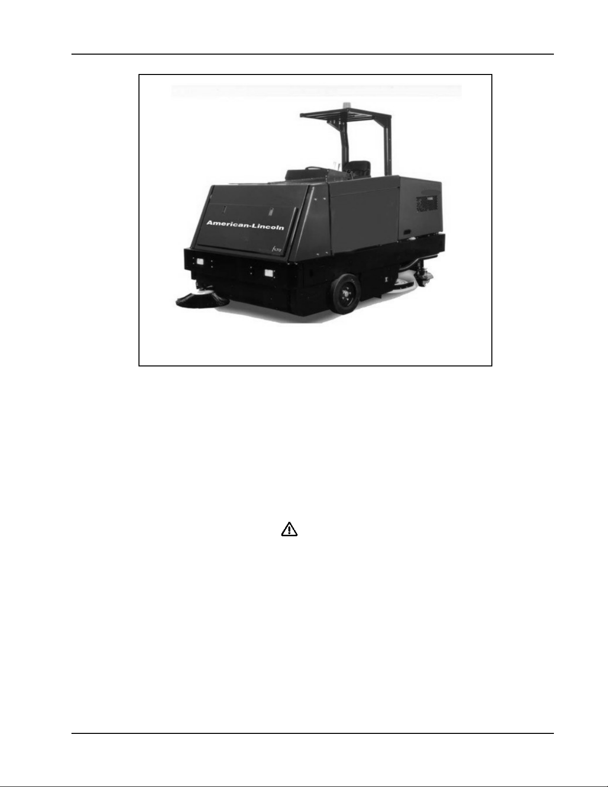
FIGURE 1
YOUR 7765/7760 MACHINE HAS BEEN SHIPPED COMPLETE, BUT DO NOT ATTEMPT TO OPERATE WITHOUT FOLLOWING
THESE INSTRUCTIONS.
PREPARING THE MACHINE FOR OPERATION
1. Connect and tighten battery cables.
2. Fill the tank with REGULAR GRADE unleaded gasoline; Diesel fuel if equipped with diesel engine.
WARNING
Never fi ll tank while engine is running. Always be sure fuel container and sweeper are
electrically connected before pouring fuel. This can easily be done by permanently attaching one end of an insulated wire to
the container with battery clip on the opposite end.
3. Check engine crankcase oil level. Although properly lubricated at factory, check before starting engine. No special brand oil is
used. Recommended number of operating hours before the initial oil change is the same as normal. See Maintenance.
4. Check radiator coolant level. Permanent type antifreeze is added at the factory to provide protection to approximately -35° F (37°
C). To retain this protection level, always mix 1 part water to 1 part antifreeze.
5. Check oil level in the hydraulic reservoir located at center of machine beside the engine. Oil fi ll level should be two (2) inches (5
cm.) below fi ller neck assembly. If oil is required, add HYDRAULIC FLUID ONLY, automatic transmission fl uid FORD type “F”. After
the fi rst 50 operating hours, service must be performed on your engine to insure future high performance and trouble-free operation.
See Maintenance.
American-Lincoln Technology FORM NO. 56041667 - 5
7765 / 7760
Page 6

CAUTIONS AND WARNINGS
SYMBOLS
American-Lincoln™ - Alto uses the symbols below to signal potentially dangerous conditions. Always read this information
carefully and take the necessary steps to protect personnel and property.
DANGER!
Is used to warn of immediate hazards that will cause severe personal injury or death.
WARNING!
Is used to call attention to a situation that could cause severe personal injury.
CAUTION!
Is used to call attention to a situation that could cause minor personal injury or damage to the machine or other property.
Read all instructions before using.
GENERAL SAFETY INSTRUCTIONS
Specifi c Cautions and Warnings are included to warn you of potential danger of machine damage or bodily harm.
DANGER!
• This machine emits exhaust gases (carbon monoxide) that can cause serious injury or death, always provide adequate
ventilation when using machine.
WARNING!
• This machine shall be used only by properly trained and authorized persons.
• While on ramps or inclines, avoid sudden stops when loaded. Avoid abrupt sharp turns. Use low speed down hills. Clean only
while ascending (driving up) the ramp.
• To avoid hydraulic oil injection or injury always wear appropriate clothing and eye protection when working with or near hydraulic
system.
• Turn the key switch off (O) and disconnect the batteries before servicing electrical components.
• Never work under a machine without safety blocks or stands to support the machine.
• Do not dispense fl ammable cleaning agents, operate the machine on or near these agents, or operate in areas where fl ammable
liquids exist.
• Do not clean this machine with a pressure washer.
CAUTION!
• This machine is not approved for use on public paths or roads.
• This machine is not suitable for picking up hazardous dust.
• Use care when using scarifi er discs and grinding stones. American-Lincoln™ - Alto will not be held responsible for any damage to
fl oor surfaces caused by scarifi ers or grinding stones.
• When operating this machine, ensure that third parties, particularly children, are not endangered.
• Before performing any service function, carefully read all instructions pertaining to that function.
• Do not leave the machine unattended without fi rst turning the key switch off (O), removing the key and applying the parking
brake.
• Turn the key switch off (O) before changing the brushes, and before opening any access panels.
• Take precautions to prevent hair, jewelry, or loose clothing from becoming caught in moving parts.
• Use caution when moving this machine in below freezing temperature conditions. Any water in the solution or recovery tanks or in
the hose lines could freeze.
• Before use, all doors and hoods should be properly latched.
SAVE THESE INSTRUCTIONS
6 - FORM NO. 56041667 American-Lincoln Technology
7765 / 7760
Page 7

CONSIGNES DE PRUDENCE ET DE SECURITE
SYMBOLES
American-Lincoln™ - Alto utilise les symboles reproduits ci-dessous pour attirer l’attention de l’opérateur sur des situations potentiellement
dangereuses. Il est donc conseillé de lire attentivement ces indications et de prendre les mesures adéquates en vue de protéger le
personnel et le matériel.
DANGER !
Ce symbole est utilisé pour mettre l’opérateur en garde contre les risques immédiats pouvant provoquer des dommages corporels
graves, voire entraîner la mort.
ATTENTION !
Ce symbole est utilisé pour attirer l’attention sur une situation susceptible d’entraîner des dommages corporels graves.
PRUDENCE !
Ce symbole est utilisé pour attirer l’attention de l’opérateur sur une situation qui pourrait entraîner des dommages corporels minimes ou
des dommages à la machine ou à d’autres équipements.
Lire toutes les instructions avant d’utiliser l’appareil.
CONSIGNES GENERALES DE SECURITE
Les consignes spécifi ques de prudence et de sécurité mentionnées ici ont pour but de vous informer de la survenance de tout risque
de dommages matériels ou corporels.
DANGER !
• Les gaz d’échappement (monoxyde de carbone) évacués par la machine peuvent entraîner de graves dommages corporels, voire
la mort. Veillez donc toujours à bénéfi cier d’une ventilation suffi sante lorsque vous utilisez la machine.
ATTENTION !
• Cette machine ne pourra être utilisée que par du personnel parfaitement entraîné et dûment autorisé.
• Evitez les arrêts subits lorsque la machine est chargée et se trouve sur des rampes ou des plans inclinés. Evitez les virages serrés. Adoptez
une vitesse réduite lorsque la machine est en descente. Ne nettoyez que lorsque la machine monte la pente.
• Lorsque vous utilisez le système hydraulique ou travaillez à proximité de celui-ci, veillez à porter une tenue appropriée et des lunettes de
protection afi n d’éviter tout risque de blessures ou toute projection d’huile.
• Positionnez la clé de contact sur off (O) et déconnectez les batteries avant de procéder à l’entretien des composants électriques.
• Ne travaillez jamais sous une machine sans y avoir placé, au préalable, des blocs de sécurité ou des étais destinés à soutenir la
machine
• Ne déversez pas d’agents nettoyants infl ammables, ne faites pas fonctionner la machine à proximité de ces agents ou d’autres liquides
infl ammables.
• Ne nettoyez pas cette machine avec un nettoyeur à pression.
PRUDENCE !
• Cette machine n’est pas conçue pour une utilisation sur les chemins ou voies publiques.
• Cette machine n’est pas conçue pour le ramassage des poussières dangereuses.
• Faites extrêmement attention lorsque vous utilisez des disques de scarifi cateur et des meules. American-Lincoln™ - Alto ne pourra, en
aucun cas, être tenu pour responsable des dommages occasionnés à vos sols par ce type d’équipement.
• Lors de l’utilisation de cette machine, assurez-vous que des tiers, et notamment des enfants, ne courent pas le moindre risque.
• Avant de procéder à toute opération d’entretien, veuillez lire attentivement toutes les instructions qui s’y rapportent.
• Ne laissez pas la machine sans surveillance sans avoir, au préalable, coupé le contact, enlevé la clé de contact (O) et tiré le frein à
main.
• Positionnez la clé de contact sur off (O) avant de remplacer les brosses ou d’ouvrir tout panneau d’accès.
• Prenez toutes les mesures nécessaires pour éviter que les cheveux, les bijoux ou les vêtements amples ne soient entraînés dans les
parties mobiles de la machine.
• Faites attention lorsque vous déplacez cette machine dans un endroit où la température peut descendre sous 0°. Car l’eau contenue dans
la solution, dans les réservoirs de récupération ou dans les conduites risquerait de geler.
• Avant utilisation, toutes les portes et capots doivent être correctement fermés.
CONSERVEZ SOIGNEUSEMENT CES INSTRUCTIONS
American-Lincoln Technology FORM NO. 56041667 - 7
7765 / 7760
Page 8
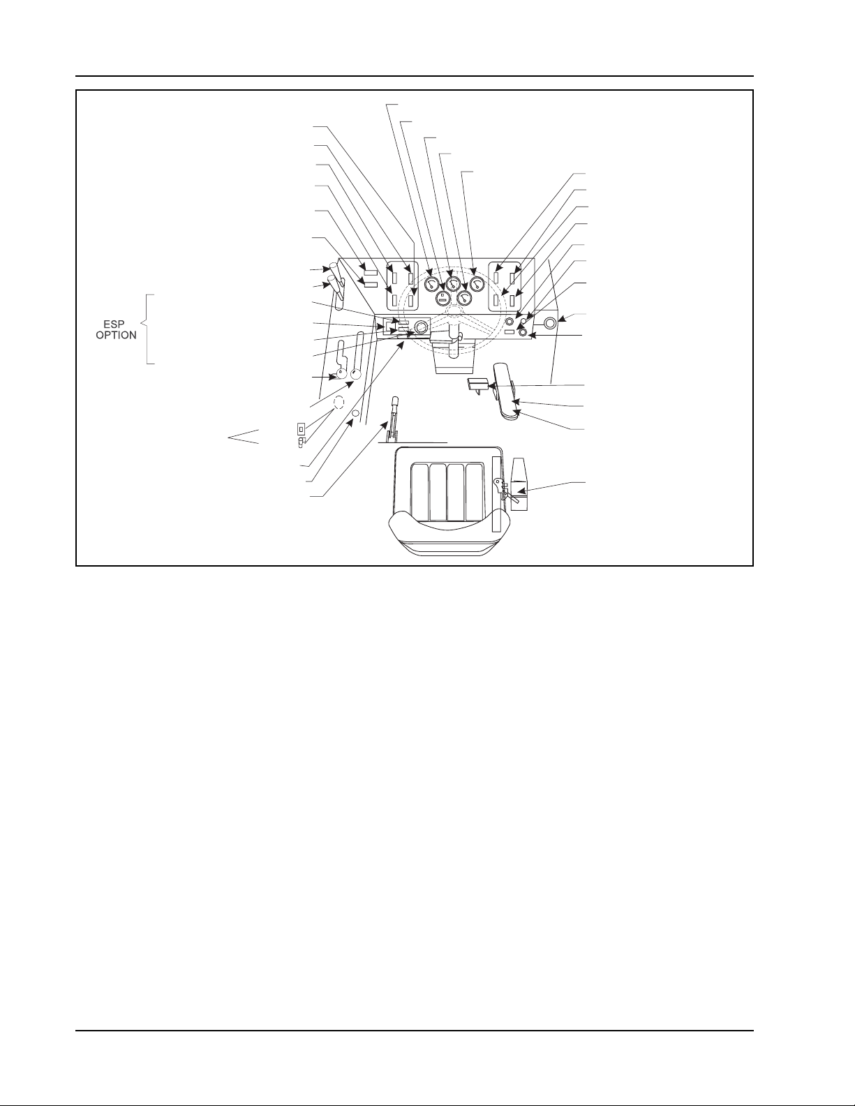
OPERATIONS OF CONTROLS AND GAUGES
WATER TEMPERATURE GAUGE
BRUSH ROTATION SWITCH
SQUEEGEE SWITCH
SCRUB BRUSH LIFT SWITCH
BRUSH PRESSURE SWITCH
HIGH RECOVERY
WARNING LIGHT
LOW SOLUTION
WARNING LIGHT
HOPPER LIFT
HOPPER DUMP DOOR
SOLUTION HIGH LIGHT
RECYCLING SYSTEM SWITCH
DETERGENT LOW LIGHT
DETERGENT FLOW KNOB
SWEEPING BROOM
LIFT CONTROL
SOLUTION CONTROL
THROTTLE
CHECK ENGINE LIGHT (GAS/LP)
PARKING BRAKE
GAS/LP
DIESEL
TURN SIGNAL
HOUR METER
FUEL GAUGE
OIL PRESSURE GAUGE
VOLT METER
MAIN BROOM SWITCH
SIDE BROOM SWITCH
DUST CONTROL SWITCH
FILTER SHAKER SWITCH
IGNITION SWITCH
LIGHT SWITCH
GLOW PLUG SWITCH
(DIESEL ONLY)
SIDE BROOM LIFT
HORN PUSH BUTTON
FOOT BRAKE
BACKUP ALARM SWITCH
ACCELERATOR &
DIRECTIONAL
CONTROL PEDAL
SEAT ADJUSTMENT
P-5101ecp FIGURE 2
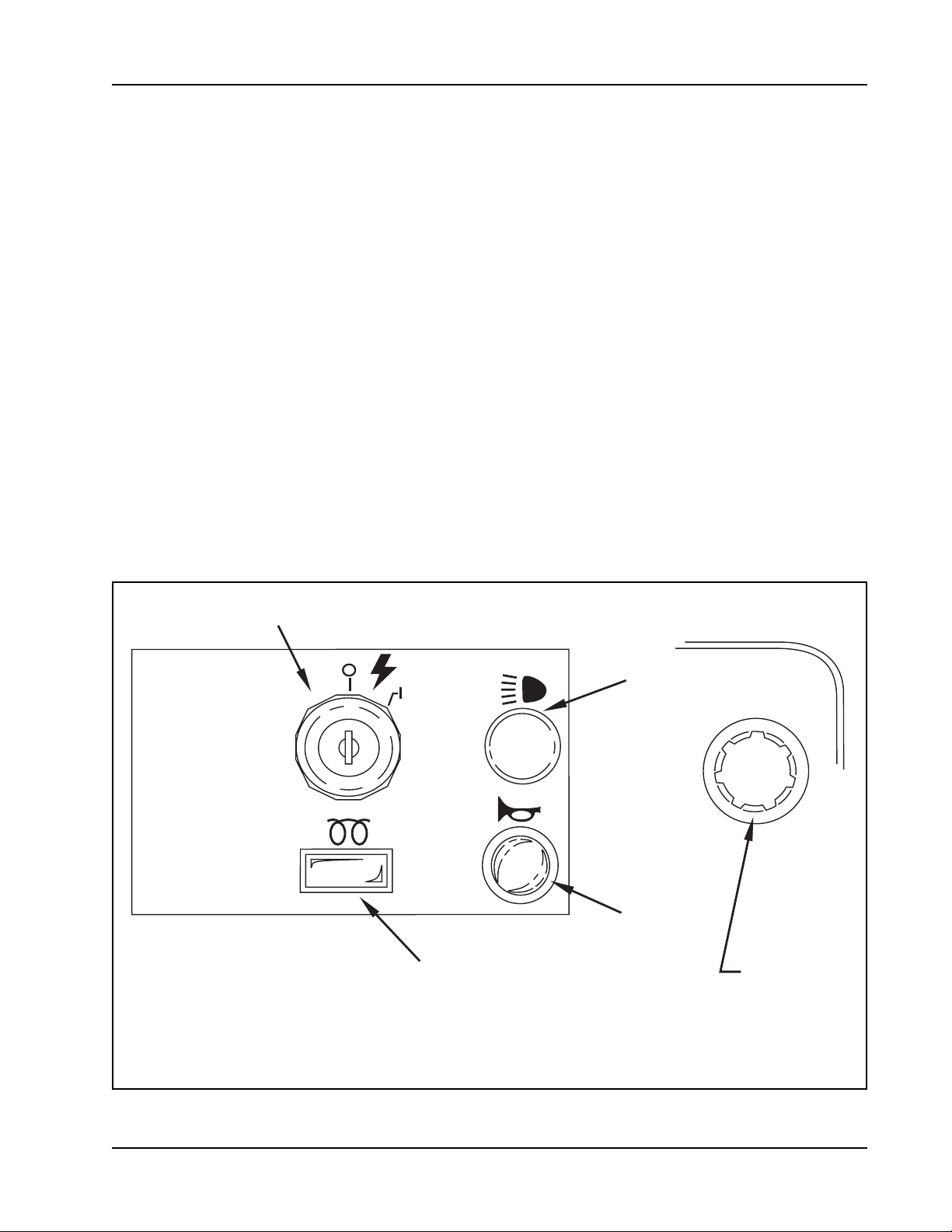
IGNITION SWITCH
The keyed ignition switch is located to the right of the steering column on the front face of the instrument console. It has four positions.
1. The key turned to the center “OFF” position will shut off the engine. The following items can be activated in the “OFF” position.
(A.) Horn
(B.) Light Options
2. The key turned to the right “IGN/ON” position will allow all the following items to be activated (but will NOT start the engine):
(A) Horn
(B) Light Options
(C) Turn Signals
(D) Instrument Panel Gauges
3. The key turned to the far right “START” position will start the engine. This position is a momentary position. The key will revert to
the “IGN/ON” position when it is released.
LIGHT SWITCH
The light switch is located above the horn button to the right of the steering wheel. It will work various light options that are available for
this machine, such as:
* HEAD LIGHTS
* TAIL LIGHTS
* INSTRUMENT LIGHTS
All gauges, with the exception of the hour meter, can have an optional internal instrument light.
8 - FORM NO. 56041667 American-Lincoln Technology
7765 / 7760
Page 9
OPERATIONS OF CONTROLS AND GAUGES
4-WAY TURN SIGNAL (Option)
The turn signal option is located on the steering column and works as automotive turn signals work, forward on the lever for right and
back on the lever for left. The 4-way fl asher will activate when the turn signal lever is pulled out.
GLOW PLUG SWITCH (Diesel)
Under no circumstances should any other unauthorized starting aids be used at the same time as Glow Plugs. The Glow Plug Switch is
located to the right of the steering column on the front face of the instrument console. Use the following procedure to operate:
1. Before operating the starter motor, press the “GLOW PLUG” button for 20 to 30 seconds.
2. With the “GLOW PLUG” button still depressed, engage the starter motor until the engine starts.
3. Continue to press the “GLOW PLUG” button for a few seconds after the engine has started until even running has been obtained.
4. If the engine does not start, disengage the starter motor, but keep the “GLOW PLUG” button depressed for an additional 10
to 15 seconds. Keep the Glow Plugs energized while starting the engine and for a few seconds after the engine has been running
smoothly.
HORN PUSH BUTTON
The horn button is located to the right of the steering column on the front face of instrument console. The horn button is always active.
Push the horn button to sound the horn.
SIDE BROOM LIFT (OPTIONAL FOR MANUAL DUMP)
The Side Broom Lift Lever is located to the right of the instrument console. The handle pulled back and turned to the right will raise the
side broom and lock it into position.
IGNITION
GLOW PLUG
SWITCH
(DIESEL ONLY)
LIGHTS
HORN
SIDE
BROOM
LIFT
P-4853ecp FIGURE 3
American-Lincoln Technology FORM NO. 56041667 - 9
7765 / 7760
Page 10

OPERATIONS OF CONTROLS AND GAUGES
MAIN BROOM SWITCH
The Main Broom Switch is located on the console to the right of the steering wheel in the SWEEPING section. This switch will activate
the Main Broom. This switch has two positions “ON” and “OFF”. See Sweeping Broom Lift Control.
SIDE BROOM SWITCH (Option For Manual Dump Machines)
The Side Broom Switch is located on the console to the right of the steering wheel in the SWEEPING section. This switch will activate
the Side Broom. This switch has two positions “ON” and “OFF”. See Side Broom Lift Control.
DUST CONTROL SWITCH (Wet Sweep Bypass Option - Option for Manual Dump Machine)
The Dust Control Switch is located on the console to the right of the steering wheel in the SWEEPING section. This switch will activate
the dust control system.
FILTER SHAKER SWITCH (Variable Dump Machines Only)
The Filter Shaker Switch is located on the console to the right of the steering wheel in the SWEEPING section.
NOTE - (Variable Dump Machines Only)
THE MAIN BROOM SWITCH MUST ALWAYS BE PLACED IN THE OFF POSITION BEFORE SHAKING THE FILTER. FAILURE
TO DO SO WILL RESULT IN DUST REMAINING ON THE SURFACE OF THE FILTER ENVELOPES INSTEAD OF DROPPING
INTO THE HOPPER.
The button can be used when the ignition key is in the “ignition” position. The fi lter shaker control button is used during the sweeping
cycle and the hopper unloading cycle. Use the fi lter shaker control switch to remove dust from the fi lter. Use the following procedures
to operate the fi lter shaker control switch:
1. After the machine has made a long sweeping run, turn the broom switch to the “OFF” position.
2. Push the fi lter shaker control switch for 5 to 15 seconds to allow the fi lter to unload.
SWEEPING
MAIN
BROOM
DUST
CONTROL
MAIN
BROOM
DUST
CONTROL
ON
OFF
ON
OFF
SIDE
BROOM
FILTER
SHAKER
SIDE
BROOM
FILTER
SHAKER
P-4862 FIGURE 4
3. Turn the broom switch to the “ON” position. Repeat this procedure after each long sweeping run.
NOTE - (Variable Dump Machines Only)
The main broom, side broom, dust control and fi lter shaker turn off automatically when the hopper is dumping and/or the
dump door is in a closed position. SEE HOPPER LIFT and HOPPER DUMP DOOR.
10 - FORM NO. 56041667 American-Lincoln Technology
7765 / 7760
Page 11
OPERATIONS OF CONTROLS AND GAUGES
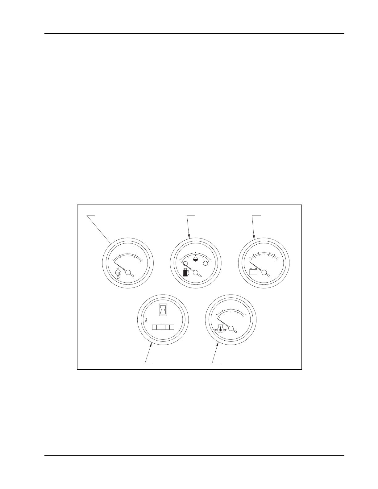
WATER TEMPERATURE GAUGE
The Water Temperature Gauge is located on the console panel above the steering wheel in the gauge cluster. The gauge is mechanical
and activated by a sender in the engine. It displays the engine coolant temperature in Fahrenheit.
HOUR METER
The Hour Meter is located on the console panel above the steering wheel in the gauge cluster. This meter is activated when the engine begins
running. The meter indicates actual “run” time of the machine. The meter can used to determine machine maintenance intervals.
FUEL GAUGE
The Fuel Gauge is located on the console panel above the steering wheel in the gauge cluster. This gauge indicates the level of fuel
contained in the fuel tank.
OIL PRESSURE GAUGE
The Oil Pressure Gauge is located on the console panel above the steering wheel in the gauge cluster. The gauge is mechanical and
activated by a sender in the engine. It displays the engine oil pressure in PSI.
VOLT METER
The Volt Meter is located on the console panel above the steering wheel in the gauge cluster. The gauge indicates the charge level of
the battery.
WATER TEMPERATURE
°F
195
100
170
220
280
91
77
104
°C
138
WATER
TEMP
HOURS
001
0
0
0
1/10
HOURMETER
P-4865 FIGURE 5
FUEL GAUGE
1/2
1/4
FUEL BATTERY
PSI
40
60
20
0
278
553
kPa
OIL
PRESS
OIL PRESSURE
12
10
+
-
80
VOLTMETER
14
16
SCRUB BRUSHES SWITCH
The Brushes Switch is located on the console to the left of the steering wheel in the “SCRUBBING” section. This switch in the position
marked “LOWER” will lower the scrub brush deck and activate the three scrub brushes. The Brush Rotation Switch and the Brush Pressure
Switch can not be activated unless this switch is in the “LOWER” position. This switch in the “RAISE” position will stop the brushes from
rotating and raise the scrub brush deck.
American-Lincoln Technology FORM NO. 56041667 - 11
7765 / 7760
Page 12
OPERATIONS OF CONTROLS AND GAUGES
BRUSH ROTATION SWITCH
The Brush Rotation Switch is located on the console to the left of the steering wheel in the “SCRUBBING” section. This switch reverses
the rotation of the scrub brushes. This switch has two positions, “NORMAL” and “REVERSED”. This switch can not be activated unless
the Scrub Brush Lift Switch is in the “LOWER” position. The switch will light when activated.
BRUSH PRESSURE SWITCH
The Brush Pressure Switch is located on the console to the left of the steering wheel in the “SCRUBBING” section. This switch applies
additional downward pressure to the scrub brushes. This switch has two positions, “NORMAL” and “HEAVY”. This switch can not be
activated unless the Scrub Brush Lift Switch is in the “LOWER” position. The switch will light when the switch can be activated.
SQUEEGEE BLADE SWITCH
The Squeegee Blade Switch is located on the console to the left of the steering wheel in the “SCRUBBING” section. This switch in the
position marked “LOWER” will lower the squeegee and activate the squeegee vacuum. This switch in the “RAISE” position will stop the
squeegee vacuum and raise the squeegee. A switch activated by the forward-reverse foot pedal will automatically raise the squeegee if
it is in the lowered position and the machine is in reverse.
HIGH RECOVERY WARNING LIGHT
The High Recovery Warning Light is located on the console to the left of the steering wheel beside the
“SCRUBBING” section. The recovery warning light will illuminate approximately 5 minutes before the recovery tank is full, giving ample
time to complete the scrubbing cycle before the mechanical fl oat shuts off the vacuum to the recovery tank.
LOW SOLUTION WARNING LIGHT
The Low Solution Warning Light is located on the console to the left of the steering wheel beside the “SCRUBBING” section. The Solution
Warning Light will illuminate when the solution tank is empty, marking the end of the
scrubbing cycle.
RECOVERY HIGH
WARNING LIGHT
LOW SOLUTION
WARNING LIGHT
HIGH
RECOVERY
LOW
SOLUTION
SCRUBBING
SCRUB
BRUSHES
BRUSH
PRESSURE
NORMAL
SQUEEGEE
BLADE
LOWER
RAISE
BRUSH
ROTATION
SQUEEGEE
BLADE LIFT
SCRUB BRUSH
LIFT
BRUSH
ROTATION
HEAVY
REVERSED
BRUSH
PRESSURE
P-4854 FIGURE 6
12 - FORM NO. 56041667 American-Lincoln Technology
7765 / 7760
Page 13

N
OPERATIONS OF CONTROLS AND GAUGES
HOPPER LIFT - (Variable Machines Only)
The Hopper Lift Lever is located to the left of the steering wheel on the left side of the driver compartment. This lever, which is marked
“HOPPER”, raises and lowers the debris hopper to ease unloading.
WARNING
The hopper may drop unexpectedly and cause injury, always engage the safety arm before working under the hopper.
HOPPER SAFETY LOCK ARM (Variable Dump Only)
WARNING
When the hopper is raised the safety arm must be engaged before any work is done under the
hopper
The Hopper Safety Lock Arm is located under the hopper assembly. After the work is complete, the safety arm must be disengaged.
HOPPER DUMP DOOR - (Variable Dump Machines Only)
The Hopper Dump Door Lever is located to the left of the steering wheel on the left of the driver compartment. This lever opens and
closes the hopper door. This lever is located below the Hopper Lift Door and is marked “DUMP DOOR”.
MANUAL DUMP HOPPER - (Manual Dump Hopper Only)
The Manual Dump Hopper Lever is located under the front bumper. To dump debris, pull the manual dump lever all the way to the
position marked open. Leave the handle in the dump position and back the machine off the pile of debris. When clear of the debris, pull
the manual dump lever to the position marked closed.
SOLUTION CONTROL
To apply solution to the scrubbing brushes, push the solution control lever forward until the desired setting is reached. The solution
rate is continuously variable from off to approximately 1-3/4 GPM at low and 3-1/2 GPM at high. To stop application of solutio n, pull
back on the lever until it stops at the “off” position. The solution warning light will illuminate when the solution tank is empty, marking
the end of the scrubbing cycle.
NOTE
For best results, discontinue application of solution 10 feet
before stopping or making a 90° or 180° turn.
SWEEPING BROOM LIFT CONTROL
The main broom lift control is located to the left of the driver seat.
To lower the main broom, grasp the lever and pull back to clear the
locking notch. Move the lever forward to the fi rst or second notch in
the elongated slot. The fi rst notch, “SWEEP”, is for normal sweeping
(2 to 3 inch [5 to 8 cm.] broom pattern). The second notch, “FLOA T”,
is for heavy sweeping (4 to 5 inch [10 to 13 cm.] broom pattern).
T o raise the main broom, pull the lever back and slide into the locking
notch. You may operate the main broom in either the “SWEEP” or
“FLOAT” position. However, the “SWEEP” position should be used
for normal sweeping and will result in increased broom life. The
“FLOAT” position should be used only when sweeping extremely
uneven areas.
NOTE - (Variable Dump Machines Only)
A switch triggered by the hopper and dump door position
controls the sweeping functions, main broom, side broom,
dust control, and fi lter shaker. The hopper must be down and
the dump door open before these functions
will work.
HOPPER
LIFT
DUMP DOOR
OPEN
MAIN BROOM
LIFT
LOWER
RAISE
HOPPER
OPEN
CLOSE
DUMP
DOOR
SWEEPING
SOLUTIO
CONTROL
HIGH
FLOAT
EEP
LOW
UP
OFF
SOLUTION
CONTROL
P-4851 FIGURE 7
American-Lincoln Technology FORM NO. 56041667 - 13
7765 / 7760
Page 14

OPERATIONS OF CONTROLS AND GAUGES
THROTTLE CONTROL
The throttle control is located on the left side console. Gas and LP equipment have a throttle switch. Diesel versions have a lever.
To operate the diesel: For full throttle, grasp the lever and push up and right to the locking notch. To reduce to idle, grasp the lever
and push it up and to the left (away from the locking notch). Let the lever lower until it rests at the bottom of the slot. “Load” (brooms
and/or brushes and/or dust control operating) and “No Load” (brooms, brushes & dust control off) RPMs are the same for gas and LP
equipment; The will be a slight drop between “Load” and “No Load” RPMs with diesels. Always return the throttle switch/lever to the
idle position before turning off the key to stop the engine.
MACHINE RPMs
IDLE “NO LOAD”
SWEEPER/ Gas/LP 950 2050
SCRUBBER (1 speed) Diesel 950 2150
SWEEPER Gas/LP 1st 950 2050
(2 speed levels) 2nd 950 2450
Diesel 1st 950 2150
2nd 950 2550
CHECK ENGINE LIGHT (MIL) - Gas, LP Only
The check engine light (MIL) is located on the left side console. If the light comes on, it indicates a problem with the engine.
Go to the GM Engine Service Manual, Section 7, for directions on how to diagnose the problem.
PARKING BRAKE
The parking brake lever is located in the left side of the driver compartment fl oor. This lever , when raised to the upright position, will “lock”
the foot brake pedal in the down position.
FOOT BRAKE
The foot brake pedal is located to the right of the steering column on the fl oor of the driver compartment. The foot brake on the front
wheels is a mechanical system actuated by the brake pedal.
LOCKED
POSITION
PARKING BRAKE
P-4888 FIGURE 8
14 - FORM NO. 56041667 American-Lincoln Technology
P-4887 FIGURE 9
7765 / 7760
Page 15

REVERSE
OPERATIONS OF CONTROLS AND GAUGES
FORWARD
P-4690 FIGURE 10
ACCELERATOR & DIRECTIONAL CONTROL PEDAL
The accelerator and directional control pedal is located on the fl oor of the driver compartment, to the right of the brake pedal. The
accelerator and directional control pedal controls machine direction and travel speed.
1. Put foot pressure on the upper portion of the pedal. The machine will move forward.
2. Increase the foot pressure on the upper portion of the pedal to increase the forward speed.
3. Put foot pressure on the lower portion of the pedal. The machine will move in reverse.
4. Increase the foot pressure on the lower portion of the pedal to increase the reverse speed.
5. To stop the machine, put light foot pressure on the opposite end of the accelerator and directional control pedal. If the machine is
moving forward put light foot pressure on the lower portion of the pedal. If the machine is moving in reverse put light foot pressure on
the upper portion of the pedal.
BACKUP ALARM SWITCH
This switch is located under the lower section of the accelerator and directional control pedal and operates the backup alarm. The alarm
makes a loud audible noise when the machine is being driven in reverse.
SEAT ADJUSTMENT
This lever is located on the right of the seat. This lever allows the seat to be adjusted forward or back when the lever is moved.
American-Lincoln Technology FORM NO. 56041667 - 15
7765 / 7760
Page 16

SCRUBBING SYSTEM OPERATING INSTRUCTIONS
SOLUTION HIGH
WARNING LIGHT
ON
OFF
RECYCLING SYSTEM
ON/OFF SWITCH
P-4895 FIGURE 11
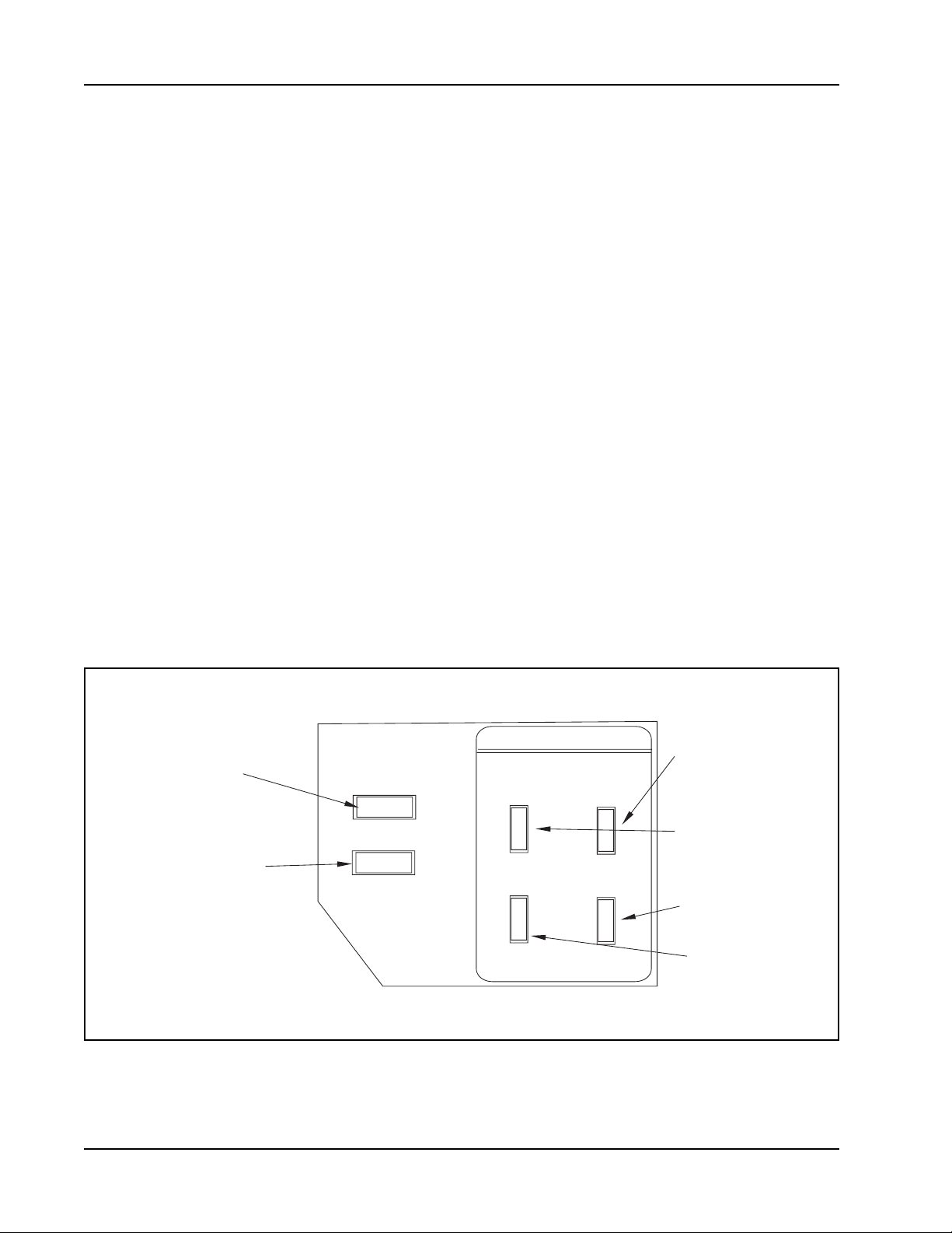
THE ESP RECYCLING CONTROL PANEL
THE ESP RECYCLING SYSTEM ON/OFF SWITCH
This switch turns the ESP recycling system on and off.
DETERGENT
FLOW KNOB
DETERGENT LOW
WARNING LIGHT
SOLUTION HIGH WARNING LIGHT
The solution high warning light will come on if the solution tank is too full of water from the recycling system.
DETERGENT LOW WARNING LIGHT
The detergent light will illuminate when the detergent tank is low, warning the operator to add detergent.
DETERGENT FLOW KNOB
This rotary knob controls the detergent fl ow into the scrubbing solution. The operator may choose from any detergent setting, for light to
heavy cleaning applications. The detergent light will illuminate when the detergent tank is low, warning the operator to add detergent.
16 - FORM NO. 56041667 American-Lincoln Technology
7765 / 7760
Page 17

RECOVERY
RECOVERY
TANK
RECOVERY
TANK
SOLUTION
TANK
SOLUTION
TANK
DETERGENT
TANK
BAFFLE
NON-RECYCLING
RECYCLING
SOLUTION
LINE
SOLTUION
TANK
RECOVERY
TANK
MVACUUM
SCRUBBING
BRUSHES
TANK
SCRUBBING SYSTEM OPERATING INSTRUCTIONS
DETERGENT
TANK
SOLUTION
TANK
RECOVERY
TANK
NON-RECYCLING
RECYCLING
P-4795 FIGURE 13
THE SCRUBBING SYSTEM - HOW IT WORKS
There are two scrubbing systems available for the 7765/7760 machine, the non-recycling or standard scrubbing system and the recycling
or ESP scrubbing system.
THE NON-RECYCLING OR STANDARD SCRUBBING SYSTEM - HOW IT WORKS
During the scrubbing process (shown in Figure 14), detergent solution water from the solution tank is fed to the solution line. There it is
fed to the fl oor where three disc scrubbing brushes work to dislodge soil.
After scrubbing, the dirty solution is vacuumed from the fl oor and discharged into the containment chamber in the forward portion of the
recovery tank, where a system of baffl es helps to clarify the solution. Sensors in each tank will indicate by lights on the control panel
when the water in the solution tank is too low or when the water in the recovery tank is too high.
ORIFICE
CHECK
VALV E
DETERGENT
TANK
DETERGENT
PUMP
P4759a
SOLUTION
TANK
SOLUTION
PUMP
FILTER
FLOW VALVE
SEPARATOR
SCRUB
BRUSH
FLOOR CONTACT
FILTER
AUTOFIL VALVE
FILL COUPLING
SQUEEGEE
RECOVERY
TANK
SOLUTION
LINE
SOLTUION
TANK
RECOVERY
TANK
VACUU
SCRUBBING
BRUSHES
P-4759a FIGURE 14
P-5103 FIGURE 15
American-Lincoln Technology FORM NO. 56041667 - 17
7765 / 7760
Page 18

RECOVERY
TANK
RECOVERY
TANK
SOLUTION
TANK
SOLUTION
TANK
DETERGENT
TANK
BAFFLE
NON-RECYCLING RECYCLING
SCRUBBING SYSTEM OPERATING INSTRUCTIONS
THE RECOVERY OR ESP SCRUBBING SYSTEM - HOW IT WORKS
During the scrubbing process (shown in Figure 16), fi ltered water from the solution tank is fed to the solution line, where it combines with
detergent from the metering pump. This mixture is then fed to the fl oor where three disc scrubbing brushes work to dislodge soil.
After scrubbing, the dirty solution is vacuumed from the fl oor and discharged into the containment chamber in the forward portion of the
recovery tank, where a system of baffl es helps to clarify the solution on its way to the pumping chamber in the rear of the recovery tank.
At intervals, a system of sensors activates the recycling pump, which sends fi ltered solution from the pumping chamber on its way to the
solution tank. Here, it is ready to be mixed with fresh, metered detergent and repeat the cycle.
DETERGENT
TANK
RECOVERY
TANK
SOLUTION
TANK
RECOVERY
TANK
P-4795-1 FIGURE 16
18 - FORM NO. 56041667 American-Lincoln Technology
7765 / 7760
Page 19

DUST CONTROL OPERATING INSTRUCTIONS
THE VARIABLE DUMP SWEEPING AND DUST CONTROL SYSTEMS - HOW THEY WORK
Variable Dump 7765/7760 machines are equipped with a sweeping and dust control system. Figure 18 shows the highest position for
the variable dump.
HOPPER
LIFT LEVER
HOPPER
DOOR LEVER
P-5104 FIGURE 18
P-5105 FIGURE 19
The debris from sweeping is thrown into the hopper (Figure 19). The baffl e system that is built into the variable dump debris hopper is
designed to minimize dust in the air while the machine is sweeping. The impeller vacuum fan pulls the lighter dust up and through a
baffl e system. The Pre-Clean Flap separates the heavier dust particles to an area below the fi lters. The dust fi lters capture the lighter
dust particles. This allows the dust fi lters to remain cleaner and need less shaking to remove dust. When the dust fi lters become clogged
the fi lter shaker switch should be pushed to start the dust shaker cycle. This will extend the life of the fi lters.
NOTE
TURN MAIN BROOM OFF FIRST
American-Lincoln Technology FORM NO. 56041667 - 19
7765 / 7760
Page 20

OPERATING INSTRUCTIONS
FILLING THE SOLUTION TANK
NON-RECYCLING or Standard Scrubbing System
1. Make sure the solution control lever is in the “Off” (rear) position.
2. Open the solution tank cover (right hand side).
3. Fill the tank with 100 gallons of water and the correct mixture of American-Lincoln #100 Industrial Cleaner for the job.
4. Close the solution tank cover.
RECYCLING or ESP System
1. Make sure the solution control lever is in the “Off” (rear) position.
2. Open the solution tank cover (right hand side).
3. Fill the solution tank as outlined above with 100 gallons of pure water.
4. Fill the detergent tank with 5 gallons of American-Lincoln #100 Industrial Cleaner.
5. Close the solution tank cover.
NOTE
Fill recovery tank halfway with water for the ESP system
WARNING
To prevent over-sudsing and machine damage,
use only AMERICAN-LINCOLN Industrial Cleaning Solution #100.
WARNING
DO NOT put gasoline, combustible or other fl ammable material
in the solution, recovery or detergent tanks.
NOTE
Before starting the engine, perform the pre-start checklist.
PRE-START CHECKLIST
1. Clean engine air fi lter element if needed
2. Check engine oil level
3. Check radiator coolant level
4. Check hydraulic fl uid level
5. Check fuel level
6. Check all systems for leaks
7. Check brakes and controls for proper operation
BEFORE STARTING ENGINE
1. Set parking brake
2. Make sure all controls are in the “Off” position
TO START ENGINE
1. Be sure accelerator and directional control pedal is in neutral.
2. Turn key to “On” position and hold it until the engine starts.
3. If engine fails to start after following the above procedures, refer to Engine Manual.
WARNING
The manufacturer does not advise storing the machine in below-freezing temperatures unless all fl uids have been drained
from the detergent, solution and recovery tanks and associated systems. When machine has been stored in below-freezing
temperatures, run engine at lowest possible settings and let machine sit 5-10 minutes to warm engine and hydraulic oil.
20 - FORM NO. 56041667 American-Lincoln Technology
7765 / 7760
Page 21

OPERATING INSTRUCTIONS
POST-START CHECKLIST (Engine Running)
1. Check main and side brooms to make sure they are free of debris which will inhibit rotation & pick-up.
NOTE: Always wear hand protection when cleaning debris from brooms and/or brushes.
2. Check squeegees to make sure there is no damage and they meet the fl oor.
TO TRANSPORT MACHINE (No scrubbing or sweeping)
1. Be sure the brooms, brushes (scrub deck) and squeegee are in the “Up” position with all other controls in the “Off” position.
2. Release parking brake.
3. Push throttle control up.
4. Push forward on the directional control pedal to place the machine in motion.
5. Vary your foot pressure on the directional control pedal to obtain desired travel speed.
6. To stop, allow directional control pedal to return to neutral (centered) position. (Pedal will automatically return to neutral when
foot pressure is released). FOR NORMAL OPERATION, DEPRESS DIRECTIONAL CONTROL PEDAL WITH HEEL INTO
NEUTRAL.
7. Push engine throttle down. Turn key to “Off”.
8. Set parking brake.
TO BEGIN THE CLEANING OPERATION
1. Choose the mode of operation (recycling ESP or non-recycling STANDARD) as dictated by the machine fi ll or machine type.
2. Bring engine to full RPM.
3. Lower the main broom.
4. Lower the side broom.
5. Turn on the main and side brooms.
6. Sweep for the length of the machine.
7. Move recovery switch to the “On” position.
8. Lower the scrub brushes.
9. Lower squeegee to the “Lower” position.
10. Move solution control lever to the desired setting.
11. Turn on the Recovery Switch for the ESP Recycling system, if applicable.
12. Begin scrubbing operation.
Single sweep and scrub the average fl oor with light to medium soil. In this operation the cleaning is accomplished in one pass with
simultaneous solution feed, sweeping, scrubbing and dirty water pick-up. The rate of solution feed and the speed of travel required will
vary with fl oor condition. This knowledge will come with operator experience.
American-Lincoln Technology FORM NO. 56041667 - 21
7765 / 7760
Page 22

HELPFUL HINTS FOR CLEANING OPERATION
SIDE AISLES
MAIN AISLE
P4134/0001
P-4134 FIGURE 23
Do not turn the steering wheel sharply when the machine is in motion. The sweeper is very
responsive to movement of the steering wheel. Do not make sudden turns.
Scrub in straight paths. Do not bump posts. Do not scrape the sides of the machine.
When the machine is in motion, do not push the directional/speed control pedal all the way forward.
This is the same as starting in “High” and will put a strain on the motor and drive system.
1. Plan your sweeping and scrubbing in advance. Try to arrange long runs with minimum stopping and
starting.
Sweep debris from narrow aisles out into main aisle ahead of time. Do an entire fl oor, or section at one
time.
2. Pick up oversize debris before sweeping.
3. Allow a few inches overlap of sweep and scrub paths. This will eliminate leaving dirty patches.
4. Don’t turn steering wheel too sharply when machine is in motion. The machine is very responsive to
movement of the steering wheel - so avoid sudden turns.
5. Try to follow as straight a path as possible. Avoid bumping into posts or scraping the sides of the
machine.
6. When placing the machine in motion, avoid slamming the directional control pedal all the way forward
quickly. This is equivalent to starting out in “HIGH” and puts needless strain on the engine and drive
system.
7. Always allow the machine to warm up before operating in cold temperatures.
8. Periodically turn sweeping (main) broom end for end to prevent the bristles from “setting” in one direction.
SIDE AISLES
WARNING
NOTE
Replace sweeping broom when bristles are worn to 3-inch (8-cm.) length. Replace disc brushes when
bristles are reduced to 1/2 inch (1.3 cm) in length. Replace squeegee rubbers when all usable edges
have become rounded with wear, impairing the wiping action.
22 - FORM NO. 56041667 American-Lincoln Technology
7765 / 7760
Page 23

POST-OPERATION & CLEAN-UP INSTRUCTIONS
TO STOP THE CLEANING OPERATION
Discontinue the cleaning operation whenever a solution or recovery warning or stop light is illuminated.
The solution light will illuminate when the solution tank is empty. At this time, discontinue the scrubbing cycle, put all controls in position
for transport and drive to the drain area. See pages 30-32 for instructions on how to drain and clean the recovery and solution tanks,
and empty the debris hopper.
The recovery warning light will illuminate approximately 5 minutes before loss of vacuum to the recovery tank. This warning period
should give ample time to complete the scrubbing cycle and transport or scrub to the drain area.
NOTE
After stopping the engine, perform this post-operation checklist.
POST-OPERATION CHECKLIST
1. Clean debris hopper. 2. Check sweeping broom for wear or damage.
3. Check all fl aps for wear, damage and adjustment. 4. Drain and clean solution tank (ESP system)
5. Clean solution fi lter screen (ESP system) 6. Drain and clean recovery tank.
7. Clean recovery tank screens and fl oats. 8. Check manifold and vacuum hoses for debris or obstructions,
backfl ush if necessary.
9. Check scrub brushes for wear or damage. 10. Check rear and side squeegees for wear, damage and adjustment.
11. Fill fuel tank. 12. Check all systems for leaks.
TO DRAIN SOLUTION TANK (RECYCLING OPERATION) (ESP System)
Draining the solution tank is accomplished by a 4-foot (92 cm.) long drain hose located under the frame channel. T o drain the tank, lower
the hose, remove the plug and drain. When the draining operation is completed, clean the solution tank as outlined below.
P-4766 FIGURE 20
TO CLEAN SOLUTION TANK (RECYCLING OPERATION) (ESP System)
Cleaning the solution tank is simplifi ed by the large access cover . Flush all deposits from the tank, also fl ush all probes and the solution
line strainer to remove any deposits - remove strainer if necessary. When the cleaning operation is completed, plug and replace the
hose. Close and secure covers.
TO DRAIN RECOVERY TANK
A 4-foot long drain hose for the recovery tank is located under the frame channel. To drain the tank, lower the hose, remove the plug
and drain. Open the recovery tank and remove the drain plug. When the draining operation is completed, fl ush and clean the recovery
tank as outlined below.
American-Lincoln Technology FORM NO. 56041667 - 23
7765 / 7760
Page 24

POST-OPERATION & CLEAN-UP INSTRUCTIONS
TO CLEAN RECOVERY TANK
The large access cover on the recovery tank simplifi es the cleaning process. Once the recovery tank lid is opened, tip out the tank.
With the recovery tank in the tipped out position (fi gure 20), fl ush all sand, sludge, debris, etc. out of the tank with a water hose, then
replace the tank and fl ush the manifold, ball fl oat screen and level switch to remove any deposits. The tank lid should be removed and
cleaned approximately every 50 running hours.
WARNING
Do not attempt to fl ush large amounts of tank debris through the drain hose - This will cause clogging and hamper future
drainage. Always fl ush the recovery tank with clean water at the end of each cleaning cycle. Never let debris accumulate,
settle and harden in the tank, tank lid,
or on associated hardware.
HOPPER
LIFT LEVER
HOPPER
DOOR LEVER
P-5104 FIGURE 21 P-4183 FIGURE 22
TOW CONTROL
SHAFT
24 - FORM NO. 56041667 American-Lincoln Technology
7765 / 7760
Page 25

POST-OPERATION & CLEAN-UP INSTRUCTIONS
TO EMPTY DEBRIS HOPPER
1. Transport or sweep and scrub to the dump site.
2. Close the hopper dump door with the hopper dump lever.
3. Raise the hopper with the hopper lift lever to the desired level.
4. Move the machine forward, over the dumpster, if necessary.
5. Open the hopper dump door with the hopper dump lever.
6. Lower the hopper with the hopper lift lever to the normal operation position.
NOTE (Variable Dump Only)
The sweep functions - main broom, side broom, dust fan, and fi lter shakers - only work when the hopper is down and the
dump door is open.
TOWING INSTRUCTIONS (See Figure 22)
1. Locate tow control shaft extension as shown in Figure 22. (See arrow)
2. To open hydraulic circuit to wheel drive motor, turn shaft 90° so that the fl ats on the shaft are parallel to the front axle.
3. After towing, turn shaft 90° so that the fl ats on the shaft are parallel to the pump centerline.
American-Lincoln Technology FORM NO. 56041667 - 25
7765 / 7760
Page 26

SERVICE CHART
For service assistance, consult the yellow pages under power sweepers and scrubbers. For best performance, replace worn
parts with genuine American-Lincoln parts.
EVERY 8 HOURS or DAILY operation check and clean/adjust if necessary:
1. Inspect panel fi lters for damage and clean.
2. Check engine oil level.
3. Check hydraulic fl uid level.
4. Check radiator core for blockage.
5. Check all fl aps for wear or damage.
6. Check brooms for wear or damage, adjust as required.
7. Check panel fi lters (clean side) for leakage.
8. Check brake pedal and parking brake.
9. Check for LP/Diesel odor at connections.
10. Check water separator (Diesel).
11. Check engine air cleaner.
12. Check hydraulic oil fi lter .
13. Check coolant level.
50 HOUR (WEEKLY) MAINTENANCE CHECKLIST
14. Solution tank (recycling or ESP system).
15. Solution fi lter screen (recycling or ESP system).
16. Recovery tank. (Include cleaning of tank lid.)
17. Recovery tank screens and fi lters.
18. Scrub brushes for wear or damage.
19. Rear and side squeegees for wear or damage.
20. Check tension on all belts.
21. Check battery electrolyte level. (Unless Maintenance-Free Battery)
22. Check all hydraulic hoses for wear or cuts.
23. Rotate main broom (end-to-end).
24. Clean or replace panel fi lters.
Perform recommended engine maintenance (see engine manual if applicable).
100 HOUR MAINTENANCE CHECKLIST
25. Change crankcase oil.
26. Change engine oil fi lter .
27. Lubricate drive wheel, l swivel wheel bearings, and steering rack guide (engine side above rear wheel).
MAKE SURE TO GREASE ZERK LOCATED ABOVE PINION RACK (See Rear Wheel Assy., Chapter 2)
28. Lubricate front wheel bearings.
29. Lubricate all moving joints.
30. Check brake pads for wear and adjust accordingly.
31. Lubricate all 6 (Diesel)/4 (Gas/LP) DANHOUSER Bushings with NAPA #765-1363 or equivalent anti-seize
lubricant. The bushings are located on the steering, scrub deck lift, squeegee lift, main broom lift, both threaded ends of
the throttle cable and variable dump door cylinders. Perform recommended engine maintenance (see engine manual if
applicable).
250 HOUR MAINTENANCE CHECKLIST
32. Lubricate squeegee casters.
33. Clean solution tank and fi lter screen.
34. Replace engine air fi lter element.
35. Flush radiator coolant system.
36. Remove spark plug - clean or replace (Gas/LP).
37. Check distributor and points - service or replace (Gas/LP).
38. Clean and lubricate governor linkage (Diesel).
39. Replace fuel fi lter.
40. Replace hydraulic fi lter element.
Perform recommended engine maintenance (see engine manual if applicable).
400 HOUR MAINTENANCE CHECKLIST
41. Clean hydraulic reservoir.
42. Clean hydraulic intake strainer.
43. Change hydraulic fl uid.
Perform recommended engine maintenance (see engine manual if applicable).
26 - FORM NO. 56041667 American-Lincoln Technology
7765 / 7760
Page 27

SERVICE CHART
4
13, 35
38
26
21
9
31
41, 42, 43
20
2, 25
8 15, 33 14
39 36, 37
11, 3 4 17
3
29
16
31
1, 7, 24
12, 40
31
27
28, 30
32
19
18
29 5 31 6, 23
American-Lincoln Technology FORM NO. 56041667 - 27
7765 / 7760
Page 28

1
GENERAL MACHINE MAINTENANCE
LUBRICATION
6
3
4
4
5
3
P-5114 FIGURE 24
100 Hour Lubrication
1. Lubricate drive wheel swivel, wheel bearings and steering rack guide.
2. Lubricate front wheel bearings.
3. Lubricate all moving joints.
4. Lubricate all 6 (Diesel)/4 (Gas/LP) DANHOUSER Bushings with NAPA #765-1363 or equivalent anti-
seize lubricant. The bushings are located on the steering, scrub deck lift, squeegee lift, main broom lift, both
threaded ends of the throttle cable and the variable dump door cylinders.
4
2
250 Hour Lubrication
5. Lubricate squeegee casters.
6. Lubricate governor linkage (Diesel).
Use good grade multipurpose grease. Avoid using too much grease.
28 - FORM NO. 56041667 American-Lincoln Technology
7765 / 7760
Page 29

GENERAL MACHINE MAINTENANCE
ENGINE
Read and follow all the instructions in the Engine Manual Section. Due to the nature of work being done by the
machine, extra care must be taken to protect the engine from these elements. Check the oil each day before
starting operations. Be sure to check the air fi lter cap’s dust collector and empty as necessary. Also check the
air cleaner and replace as conditions demand. Do not let the engine become coated with dust and dirt.
RIGHT,BROOM
CHAMBER DOOR
MAIN
BROOM
DRIVE
HUB
IDLER
ARM
RETAINING
BOLT
P-5116 FIGURE 28
TO REMOVE MAIN SWEEPING BROOM
1. Open the left broom chamber door.
2. Put the main broom control in the “SWEEP” position.
3. Remove the retaining bolt.
4. Remove the idler arm assembly.
5. Remove the main broom and discard.
6. Put a new main broom in the broom chamber.
7. Rotate the new broom to the right on the drive hub until it engages the drive hub broom tabs.
8. Put the idler arm assembly in place.
9. Put the retaining bolt in place and tighten.
10. Close the broom chamber door.
11. Start the engine.
12. Put the broom lever in the “SWEEP” position.
13. Let the broom sweep in place for 30 seconds.
14. Put the broom lever in the “UP” position.
15. Back the machine off the test spot.
16. Inspect the polished area where the broom swept, for broom bristle contact with the fl oor. The area of
broom bristle contact with the fl oor should be 2 to 3 inches (5 to 8 cm.) wide.
American-Lincoln Technology FORM NO. 56041667 - 29
7765 / 7760
Page 30

GENERAL MACHINE MAINTENANCE
MAIN BROOM LEVEL ADJUSTMENT
The main broom level is factory set and shouldn’t need adjustment, if the level gets out of adjustment and the
broom bristle contact pattern is not an even 2” to 3” (5 to 8 cm.) wide. Adjust the broom arm lift frame. The frame
is supported by two fl ange bearings. These bearings are located inside the broom doors. The carriage bolts on
the two end fl anges must be loosened. The frame can then be leveled and the bolts tightened.
HOW TO ADJUST MAIN BROOM WEAR PATTERN
When the bristles of the broom begin to wear out the following adjustments may be made to keep a 2-inch
(5-cm.) broom pattern.
1. Loosen the nut located in the engine compartment.
2. Set the broom lever to the “Sweep” position and adjust the lock nut to obtain a 2-inch (5 cm) broom
pattern. The lock nut will move the adjusting rod that adjusts the sweeping pattern of the broom for wear.
RAISE OR
LOWER FOR
WEAR ADJUSTMENT
FLOOR
CONTACT
AREA
FORWARD
SIDE
BROOM
3
P-5117 FIGURE 29
SIDE BROOM LEVEL ADJUSTMENT
As the side broom wears, loosen the two wear adjusting bolts and slide the broom-motor assembly into a position
so that the broom contacts the fl oor at a 3 degree angle when lowered as shown in Figure 29.
SIDE BROOM REPLACEMENT
Put the side broom lift control in the “UP” position. Remove the retaining screw in the bottom middle of the side
broom. Remove the side broom. Transfer the side broom fl ange spacer and screws to the replacement side
broom. Put the replacement side broom on the shaft. Put the retaining screw in position and tighten.
30 - FORM NO. 56041667 American-Lincoln Technology
7765 / 7760
Page 31

1/16"
SET FLAP
EVEN WITH FLOOR
P-4793 FIGURE 30
GENERAL MACHINE MAINTENANCE
FLAPS
The urethane and rubber fl aps are susceptible to damage and should be inspected regularly and maintained in
good condition. The side fl aps are adjustable and should be maintained at approximately 1/16” (16 mm.) above
the fl oor. The front and rear fl aps have no provision for adjustment.
All fl aps should be replaced when worn or damaged to such an extent that they couldn’t perform their
function.
American-Lincoln Technology FORM NO. 56041667 - 31
7765 / 7760
Page 32

GENERAL MACHINE MAINTENANCE
P-4762 FIGURE 31
BRUSH
LATCH
SCRUB BRUSH REPLACEMENT
1. Raise the scrub brush deck by pressing the “Scrub Brush” Switch on the instrument panel.
2. Press the brush latches in to release the scrub brush.
3. Remove old scrub brush.
4. Snap new brush into place.
COVERS AND LATCHES
The covers have been designed to allow access, either by hinge or removal, to all areas of the machine. No
maintenance is required. For lubrication of latches see Lubrication Section.
SOLUTION WARNING LIGHT
The solution warning light will illuminate when the solution tank is empty. This part of the level control system
requires no maintenance. If the system fails to operate, consult the Electrical Troubleshooting Guide.
RECOVERY WARNING LIGHT
The recovery warning will illuminate approximately 5 minutes before loss of vacuum to the recovery tank. This
part of the level control system requires no maintenance, except for daily cleaning of the tank level switch. If the
system fails to operate, consult the Electrical Troubleshooting Guide.
SOLUTION CONTROL (Non-Recycling or Standard)
The solution control lever controls the amount of solution applied to the scrubbing brushes. Except for a few
drops of oil applied to the lever pivot every 100 hours, the system should require no major maintenance.
The solution control should shut off completely with the lever in the (rear) “off” position. If complete shut off does
not occur, the control cable should be adjusted.
SOLUTION CONTROL (RECYCLING or ESP System)
In the recycling mode, the solution control lever is also used to activate the detergent pump. If the detergent
pump fails to operate (engine running) when the solution control lever is moved into the low to high range,
fi rst check the circuit by manually activating the switch. If the detergent pump does not operate at this time, a
further electrical or mechanical check is indicated. (See Electrical Troubleshooting Guide or Detergent Pump
Troubleshooting).
32 - FORM NO. 56041667 American-Lincoln Technology
7765 / 7760
Page 33

GENERAL MACHINE MAINTENANCE
RECYCLING PUMP ESP System
The recycling pump is located directly behind and under the recovery tank. The pump is electric and except for
daily cleaning of the pump intake screens, it requires no regular maintenance.
NOTE
Do not run pump dry. The unit depends on the liquid pumped for lubrication.
RECYCLING (ESP) PUMP STORAGE
Always drain pump for extended storage, especially when freezing temperatures may be encountered.
REAR SQUEEGEE
The squeegee will require service when the inner edges of the blades become round with wear, impairing the
wiping action or water pickup. To service the rear squeegee use the following steps:
1. Loosen the four aluminum knobs (item 10, these hold the squeegee tool to the squeegee support)
2. Remove the squeegee tool and turn upside down to service the blades or caster wheels. The squeegee
blades are designed to fl ip over and use another unworn edge (item 5 & 6).
To service the blades:
1. Loosen the clamp bolts, which clamp items 8 & 9 together.
2. Loosen far enough to slip the end clamp brackets off the squeegee tool. This will allow fl ipping the blades
or installing new blades.
3. Install blades so that outer blade is 3/16” longer than inner blades, this is achieved by assembling the top
edge of the blade against the squeegee tool weldment.
4. Reinstall squeegee clamp band and tighten clamp bolt tight.
5
10
6
APPLY NEVERSEIZE
8
P5165/9907
9
P-5165
SQUEEGEE CASTER WHEELS
Grease caster wheel zerks (2) on each caster should be greased each time the blades are serviced for a total
of 3 caster wheels.
ADJUSTING CASTERS
Lower squeegee on a fl at surface, making sure the rear squeegee blade is perpendicular to the surface. Adjust
caster 3/16” above the fl at surface, Lock jam nuts.
American-Lincoln Technology FORM NO. 56041667 - 33
7765 / 7760
Page 34

GENERAL TROUBLESHOOTING
PROBLEM
Sweeping does not
function
Poor water pick up at
squeegee
Water spill from squeegee
PROBABLE CAUSE
1. Dump door closed
2. Hopper is raised
3. Hopper switch out of adjustment
1. Side or rear squeegee are worn or damaged
2. Clogging in water pick up
3. Air leaks in suction hose and connection
4. Air leaks at recovery tank cover and/or
manifold gaskets
5. Poor vacuum
6. Drain hose or drain plug leakage or not
closed properly..
1. Side squeegee blades, poor contact with
floor
2. Squeegee blades worn or damages
3. Too much solution being applied before
making turns
REMEDY
1. Open dump door
2. Lower hopper
3. Adjust hopper switch
1. Examine squeegee rubber blade for
cuts or worn spots.
2. Repair or replace hose and connection
3. Repair or replace gaskets
4. Check vacuum motor
5. Check seal on recovery tank
6. Close, repair or replace drain plug in
recovery tank.
1. Readjust blades for proper contact
2. Replace or adjust
3. Shut off solution flow 5' to 10'
Lack or suction at rear
4. Brushes rotating opposite direction
1. Clogged suction hose or pick up tool
2. Loose connections between suction hose
and squeegee or between hoses or
manifold inlet.
3. Vacuum motor not operating
4. Vacuum float cage clogged
5. Vacuum float shut off
4. Check position of switches.
1. Disconnect suction hose from
squeegee; flush squeegee & hoses.
2. Check all hose connections for
looseness or damage.
3. Check hydraulic motor in recovery
4. Clean perforated metal thoroughly
5. Excessive solution in recovery drain
tank. Excessive foam build up,
change cleaning chemical mixture.
Use A-L approved materials.
34 - FORM NO. 56041667 American-Lincoln Technology
7765 / 7760
Page 35

GENERAL TROUBLESHOOTING
PROBLEM
Poor scrubbing
Engine runs, but machine
will not move on level
ground
Machine moves slowly
PROBABLE CAUSE
1. Worn scrubbing brushes
2. Incorrect method of operation
3. Wrong cleaning agent or mixture
4. Poor solution distribution
1. Foot pedal and/or linkage jammed or not
adjusted
2. Front wheels jammed or brakes locked
3. Hydraulic pump trouble
4. Rear wheel hydraulic motor, broken shaft
key, broken shaft, ect.
1. Low hydraulic oil level
REMEDY
1. Inspect brushes. If worn to ½”
(1.3cm) or less, replace all 3 brushes
2. Check scrubbing procedures, brush
pressure, type of brush, solution flow,
& cleaning chemical used. For
extreme conditions double scrubbing
may be necessary.
3. Use A-L recommended materials
4. Clean out distribution tube & metering
holes to brushes. Check feed hose
& clean if necessary. Check valve &
cable control system.
1. Check pedal linkage
2. Check wheels and brakes
3. Check & repair pump, check tow valve.
See CESSNA information.
4. Check & repair. See Char-Lynn
information
1. Add oil to reservoir
Hydraulic pump making
excessive noise
2. Brake dragging
3. Hydraulic oil temp, too high
4. Worn hydraulic pump or drive wheel motor
1. Clogged inlet strainer or suction line
2. Air bubbles in hydraulic fluid
3. Hydraulic pump is worn or damaged
2. Check brakes
3. Check oil level, add SAE 5 (FORD
Type F) ATF, if required
4. See hydraulic CESSNA
1. Clean inlet strainer. Drain & flush
reservoir, if oil is dirty. Refill with clean
SAE 5 (FORD Type F) ATF.
2. Check for low hydraulic fluid level,
leaking fittings or hoses
3. See CESSNA Pump Section
American-Lincoln Technology FORM NO. 56041667 - 35
7765 / 7760
Page 36

TECHNICAL SPECIFICATIONS (as installed and tested on the unit)
Model 7765 Petrol (VD) 7765 Petrol (MD)
7765 LPG (VD) 7765 LPG (MD)
7765 Diesel (VD) 7765 Diesel (MD)
Model No. 505-255 505-258
505-256 505-259
505-257 505-260
Sound Pressure Level (ISO 11201) dB (A) 89.4 89.4
Sound Power Level (ISO 3744) dB (A) Lwa 109.0 Lwa 109.0
Total Weight lbs/kg 4,350 / 1973 3,900 / 1769
Vibrations at the Hand Controls (ISO 5349-1) m/s2 0.89 m/s
Vibrations at the Seat (EN 1032) m/s2 0.31 m/s
Gradeability
Transport 14.1% (8°) 14.1% (8°)
Cleaning 10.5% (6°) 10.5% (6°)
Model 7760 Petrol (VD) 7760 Petrol (MD)
7760 Diesel (VD) 7760 Diesel (MD)
Model No. 505-255CE 505-258CE
505-257CE 505-260CE
Sound Pressure Level (ISO 11201 dB (A) 89.4 89.4
Sound Power Level (ISO 3744) dB (A) Lwa 109.0 Lwa 109.0
Total Weight lbs/kg 4,350 / 1973 3,900 / 1769
Vibrations at the Hand Controls (ISO 5349-1) m/s2 0.89 m/s
Vibrations at the Seat (EN 1032) m/s2 0.31 m/s
Gradeability
Transport 14.1% (8°) 14.1% (8°)
Cleaning 10.5% (6°) 10.5% (6°)
2
2
2
2
0.89 m/s
0.31 m/s
0.89 m/s
0.31 m/s
2
2
2
2
36 - FORM NO. 56041667 American-Lincoln Technology
7765 / 7760
Page 37

Page 38

Page 39

Page 40

14600 21st Avenue North
Plymouth, MN 55447-3408
www.americanlincoln.com
Phone: 800-331-7692
Fax: 877-877-2586
©2007 American-Lincoln
 Loading...