

AMERICAN-LINCOLN
TECHNOLOGY
OPERATOR'S
MANUAL &
PARTS LIST
Beginning with Serial No. 630951
READ THIS BOOK
This book has important information for the use and safe operation of this machine. Failure
to read this book prior to operating or attempting any service or maintenance procedure to
your machine could result in injury to you or to other personnel; damage to the machine or to
other property could occur as well. you must have training in the operation of this machine
before using it. If you or your operator (s) cannot read English, have this manual explained
fully before attempting to operate this machine.
Si Ud. o sis operadores no pueden leer el Inglés, se hagen explicar este manual completamente
antes de tratar el manejo o servicio de esta máquina.
All directions given in this book are as seen from the operator's position at the rear of the machine.
6150
POWER
SWEEPER
ISO 9001
U
®
L
#
FILE A2287
Part No. 2-86-00188 Printed in the
American-Lincoln 1-1
6150
1996 American-Lincoln® USA

TABLE OF CONTENTS
MACHINE SPECIFICATIONS .................................................................................................................. 1-6
MACHINE DIMENSIONS ......................................................................................................................... 1-8
MACHINE PREPARATION ...................................................................................................................... 1-9
SAFETY PRECAUTIONS ........................................................................................................................ 1-10
SWEEPER CONTROLS/INSTRUMENTS ................................................................................................ 1-12
HORN BUTTON ................................................................................................................................ 1-12
LIGHT SWITCH ................................................................................................................................. 1-12
GLOW PLUG SWITCH ..................................................................................................................... 1-12
CHOKE CONTROL ........................................................................................................................... 1-12
KEY SWITCH ................................................................................................................................... 1-13
ENGINE SPEED SWITCH ................................................................................................................ 1-13
FUEL GAUGE .................................................................................................................................. 1-13
FOOT BRAKE .................................................................................................................................. 1-14
PARKING BRAKE ............................................................................................................................ 1-14
FOOT PEDAL ................................................................................................................................... 1-14
FORWARD MOVEMENT .................................................................................................................. 1-14
BACKWARD MOVEMENT ............................................................................................................... 1-14
WARNING BANK .................................................................................................................................... 1-15
ENGINE TEMP LIGHT ................................................................................................................ 1-15
ENGINE OIL PRESSURE LIGHT ................................................................................................ 1-15
CHARGING SYSTEM LIGHT ...................................................................................................... 1-15
DUST CONTROL LIGHT ............................................................................................................. 1-15
HOPPER TEMPERATURE LIGHT .............................................................................................. 1-15
DUMP DOOR LIGHT .................................................................................................................. 1-15
SEAT POSITION ADJUSTMENT ....................................................................................................... 1-16
TURN SIGNALS (OPTION) ............................................................................................................... 1-16
BACK-UP ALARM ............................................................................................................................ 1-16
BATTERY CONDITION METER ........................................................................................................ 1-16
FILTER SHAKER SWITCH ............................................................................................................... 1-17
DUST CONTROL SWITCH ................................................................................................................ 1-17
BROOM CONTROL LEVER .............................................................................................................. 1-17
SIDE BROOM LEVER ...................................................................................................................... 1-18
SIDE BROOM ADJUSTMENT ........................................................................................................... 1-18
MAIN BROOM LEVER ..................................................................................................................... 1-18
MAIN BROOM ADJUSTMENT .......................................................................................................... 1-18
HOPPER DOOR LEVER .................................................................................................................. 1-19
HOPPER LIFT LEVER ...................................................................................................................... 1-19
DEBRIS DOOR ................................................................................................................................. 1-19
DUST BAFFLE ................................................................................................................................. 1-20
HOPPER SAFETY ARM................................................................................................................... 1-20
HOPPER FILTER COMPARTMENT COVER..................................................................................... 1-20
FILTER PANEL LATCH ..................................................................................................................... 1-21
HOPPER TEMPERATURE SENSOR ............................................................................................... 1-21
ENGINE COMPARTMENT LATCH .................................................................................................... 1-21
HYDRAULIC RESERVOIR LEVER SIGHT GAUGE .......................................................................... 1-22
MAIN BROOM COMPARTMENT DOORS......................................................................................... 1-22
SEAT COMPARTMENT COVER ....................................................................................................... 1-22
SEAT COMPARTMENT LATCH ........................................................................................................ 1-23
BATTERY CHARGING CONNECTOR ............................................................................................... 1-23
HELPFUL HINTS FOR SWEEPING .................................................................................................. 1-24
OPERATING INSTRUCTIONS ................................................................................................................ 1-25
BATTERY MACHINE OPERATION ................................................................................................... 1-25
GAS/LP MACHINE OPERATION ...................................................................................................... 1-25
INSTRUCTIONS BEFORE STARTING ...............................................................................................1-26
PRE-START CHECK LIST................................................................................................................. 1-26
TO START BATTERY MACHINES .................................................................................................... 1-26
TO CHARGE BATTERIES ................................................................................................................. 1-26
TO START GAS ENGINE .................................................................................................................. 1-26
TO START PROPANE ENGINE ........................................................................................................ 1-26
TO START DIESEL ENGINE ............................................................................................................. 1-27
TO DRIVE SWEEPER FOR TRANSPORT ....................................................................................... 1-27
1-2 American-Lincoln
6150

TABLE OF CONTENTS
TO SWEEP WITH THE MACHINE .................................................................................................... 1-27
TO STOP SWEEPING ......................................................................................................................1-27
TO EMPTY DEBRIS HOPPER ......................................................................................................... 1-28
POST OPERATION CHECK LIST ..................................................................................................... 1-28
BATTERY CHARGING INSTRUCTIONS ............................................................................................ 1-28
MACHINE STORAGE ....................................................................................................................... 1-29
SERVICE CHART ................................................................................................................................... 1-30
SERVICE PRECAUTIONS ...................................................................................................................... 1-32
SERVICE INSTRUCTIONS ..................................................................................................................... 1-32
MAIN BROOM .................................................................................................................................. 1-32
TO CHECK THE MAIN BROOM SWEEP PATTERN ......................................................................... 1-32
TO ADJUST THE MAIN BROOM SWEEP HEIGHT ........................................................................... 1-32
TO REPLACE THE MAIN BROOM ................................................................................................... 1-32
MAIN BROOM LEVEL ADJUSTMENT .............................................................................................. 1-33
SIDE BROOM .................................................................................................................................. 1-33
TO CHECK THE SIDE BROOM SWEEP PATTERN ......................................................................... 1-33
TO CHANGE THE SIDE BROOM HEIGHT ADJUSTMENT ................................................................ 1-33
TO CHANGE THE SIDE BROOM ..................................................................................................... 1-33
HOPPER .......................................................................................................................................... 1-34
TO CLEAN HOPPER ........................................................................................................................ 1-34
TO CHECK HOPPER SEALS ........................................................................................................... 1-34
DUST CONTROL FILTER .................................................................................................................. 1-34
TO CHECK THE DUST CONTROL FILTER ....................................................................................... 1-34
TO CLEAN THE DUST CONTROL FILTER ........................................................................................ 1-34
TO CHANGE THE DUST CONTROL FILTER ..................................................................................... 1-35
DUST FLAPS ................................................................................................................................... 1-35
TO CHECK THE DUST FLAPS ......................................................................................................... 1-35
TO ADJUST THE DUST FLAPS ........................................................................................................ 1-35
BRAKES .......................................................................................................................................... 1-36
BRAKE PEDAL ADJUSTMENT ........................................................................................................ 1-36
HYDRAULIC SYSTEM SERVICE ..................................................................................................... 1-37
TO FILL THE HYDRAULIC RESERVOIR ........................................................................................... 1-37
TO CLEAN THE HYDRAULIC SYSTEM ............................................................................................ 1-37
TO DRAIN THE HYDRAULIC RESERVOIR ....................................................................................... 1-37
TO CLEAN THE HYDRAULIC SUCTION STRAINER ......................................................................... 1-38
TO REPLACE THE RETURN FILTER ELEMENT .............................................................................. 1-38
ENGINE AIR INTAKE SERVICE ........................................................................................................ 1-38
DIESEL AIR FILTER ....... ................................................................................................................... 1-39
TO REMOVE THE DIESEL AIR FILTER ELEMENT .......................................................................... 1-39
TO CLEAN THE DIESEL AIR FILTER ELEMENT .............................................................................. 1-39
TO INSTALL THE DIESEL AIR FILTER ELEMENT ............................................................................ 1-39
GAS AIR FILTER .............................................................................................................................. 1-39
TO REMOVE THE GAS AIR FILTER ELEMENT ............................................................................... 1-40
TO CLEAN THE GAS AIR FILTER ELEMENT ................................................................................... 1-40
TO INSTALL THE GAS AIR FILTER ELEMENT ................................................................................. 1-40
ENGINE COOLING SYSTEM SERVICE ........................................................................................... 1-41
HOSES ............................................................................................................................................ 1-41
RADIATOR........................................................................................................................................ 1-41
COOLANT LEVEL ............................................................................................................................ 1-41
DRIVE BELTS .................................................................................................................................. 1-42
BATTERY SERVICE ......................................................................................................................... 1-42
TO CHARGE THE MOTICE POWER BATTERIES ............................................................................ 1-43
LP SAFETY PRECAUTIONS .................................................................................................................. 1-44
LP GAS COMPONENTS .................................................................................................................. 1-45
LP GAS SYSTEM ............................................................................................................................ 1-45
LP LIQUID WITHDRAW SYSTEM .................................................................................................... 1-45
LP CHECKLIST ................................................................................................................................ 1-45
LP GAS VAPORIZER-REGULATOR QUICK CHECK ........................................................................ 1-46
LP FUEL TANKS .............................................................................................................................. 1-46
USE AND CARE OF LP TANKS ................................................................................................. 1-46
CHANGING LP FUEL TANKS .................................................................................................... 1-47
American-Lincoln 1-3
6150

TABLE OF CONTENTS
STORAGE OF LP FUEL TANKS ................................................................................................ 1-47
STANDARD METRIC ENGINE TORQUE REQUIREMENTS .................................................................... 1-48
HYDRAULIC TORQUE REQUIREMENTS ............................................................................................... 1-49
BOLT IDENTIFICATION CHART ............................................................................................................... 1-50
DECIMAL-METRIC CONVERSION TABLE .............................................................................................. 1-51
HARDWARE LEGEND............................................................................................................................ 1-52
HARDWARE ABBREVIATIONS .............................................................................................................. 1-58
ORDER PARTS ...................................................................................................................................... 1-59
HYDRAULIC SCHEMATIC DIAGRAMS ................................................................................................... 1-60
HYDRAULIC SCHEMATIC DIAGRAMS (3 CYL. KUBOTA) ...................................................................... 1-61
CHAPTER 2 ............................................................................................................................................ 2-1
FRONT WHEEL ...................................................................................................................................... 2-3
REAR WHEEL ........................................................................................................................................ 2-4
VAC FAN ................................................................................................................................................ 2-8
BROOM DOOR ....................................................................................................................................... 2-12
FLAP ASSEMBLY (WHEEL WELL) ........................................................................................................ 2-14
MAIN BROOM LEVER ............................................................................................................................ 2-16
MAIN BROOM IDLER ............................................................................................................................. 2-17
MAIN BROOM DRIVER .......................................................................................................................... 2-18
MAIN BROOM LIFT FRAME ................................................................................................................... 2-19
SIDE BROOM ASSEMBLY ..................................................................................................................... 2-20
SIDE BROOM LIFT SYSTEM .................................................................................................................. 2-22
SIDE BROOM LEVER ............................................................................................................................ 2-24
BROOM CHAMBER FLAPS AND SEALS............................................................................................... 2-26
BRAKE PEDAL ...................................................................................................................................... 2-28
FILTER SHAKER .................................................................................................................................... 2-30
SEAT AND FLOOR ASSEMBLY.............................................................................................................. 2-32
BATTERY SEAT COMPARTMENT .......................................................................................................... 2-34
STEERING COLUMN .............................................................................................................................. 2-36
EXHAUST PIPE (3 CYL. KUBOTA DIESEL) ............................................................................................ 2-37
KAWASAKI 20 HP MUFFLER ................................................................................................................ 2-38
KUBOTA 14 HP MUFFLER ..................................................................................................................... 2-39
FRONT BUMPER .................................................................................................................................... 2-40
HYDRAULIC OIL COOLER ...................................................................................................................... 2-41
VALVE - CCONTROL AND RELIEF ......................................................................................................... 2-42
VALVE - CONTROL AND RELIEF (3 CYL. KUBOTA GAS & DIESEL) ..................................................... 2-44
FORWARD/REVERSE CONTROL .......................................................................................................... 2-46
FORWARD/REVERSE CONTROL (3 CYL KUBOTA GAS & DIESEL) ..................................................... 2-48
RESERVOIR ........................................................................................................................................... 2-52
RESERVOIR (3 CYL. KUBOTA GAS & DIESEL) ..................................................................................... 2-54
FUEL TANK (GAS) .................................................................................................................................. 2-56
FUEL TANK (DIESEL) ............................................................................................................................. 2-58
HOPPER ASSEMBLY ............................................................................................................................. 2-60
HOPPER COVERS & GASKET ASSEMBLY .......................................................................................... 2-62
HOPPER LIFT ......................................................................................................................................... 2-64
HOPPER SIDES ..................................................................................................................................... 2-65
DUMP DOOR .......................................................................................................................................... 2-66
SAFETY ARM ......................................................................................................................................... 2-68
HYDRAULIC FILTER ............................................................................................................................... 2-69
HYDRAULIC FILTER (3 CYL KUBOTA GAS & DIESEL) .......................................................................... 2-70
HYDRAULIC PUMP (GAS/LP) ................................................................................................................ 2-71
HYDRAULIC PUMP (DIESEL) ................................................................................................................. 2-72
HYDRAULIC PUMP (3 CYL. KUBOTA GAS & DIESEL) .......................................................................... 2-74
ENGINE COVER ..................................................................................................................................... 2-76
ACCESS COVER ................................................................................................................................... 2-78
BATTERY ASSEMBLY ............................................................................................................................ 2-79
BATTERY COMPARTMENT (LEFT SIDE) ............................................................................................... 2-80
ENGINE (GAS) ....................................................................................................................................... 2-82
ENGINE ( 3 CYL. KUBOTA GAS)............................................................................................................ 2-84
ENGINE (3 CYL. KUBOTA DIESEL) ........................................................................................................ 2-86
1-4 American-Lincoln
6150

TABLE OF CONTENTS
ENGINE (3 CYL. DUAL FUEL-LP) ...........................................................................................................2-88
MOTOR PUMP ELECTRICAL ASSEMBLY .............................................................................................. 2-90
HYDRAULIC HOSE DIAGRAM (BATTERY) ............................................................................................. 2-92
HYDRAULIC HOSE DIAGRAM (3 CYL. GAS & DIESEL) ........................................................................ 2-94
HYDRAULIC HOSE DIAGRAM (2 CYL. GAS) ......................................................................................... 2-96
ELECTRICAL ASSEMBLY (LIGHTS & HORN) .........................................................................................2-98
BATTERY - ELECTRICAL ASSEMBLY (2 CYL KAWASAKI GAS & DIESEL).......................................... 2-99
BATTERY - ELECTRICAL ASSEMBLY (3 CYL KUBOTA GAS & DIESEL)............................................... 2-100
ELECTRICAL HARNESS ROUTING (BATTERY) ..................................................................................... 2-102
ELECTRICAL HARNESS ROUTING (2 & 3 CYL. IC) ............................................................................... 2-104
MACHINE HARNESS CONNECTIONS (BATTERY)................................................................................. 2-106
MACHINE HARNESS CONNECTIONS (2 & 3 CYL. IC) ........................................................................... 2-107
INSTRUMENT HOUSING ........................................................................................................................ 2-108
INSTRUMENT PANEL ............................................................................................................................. 2-110
POWER PANEL (BATTERY)................................................................................................................... 2-112
DECALS ................................................................................................................................................. 2-114
DECALS (con’t) ...................................................................................................................................... 2-116
POWER PANEL CONNECTION DIAGRAM (BATTERY) .......................................................................... 2-118
#2 MOTOR POWER PANEL CONNECTION DIAGRAM (BATTERY) ....................................................... 2-119
2-CYLINDER KAWASAKI LP (CE MODELS ONLY) ................................................................................ 2-120
NOTES .................................................................................................................................................. 2-122
INSTRUMENT PANEL CONNECTION DIAGRAM .................................................................................... 2-123
INSTRUMENT PANEL HARNESS DIAGRAM .......................................................................................... 2-124
ELECTRICAL SCHEMATIC (BATTERY)................................................................................................... 2-125
ELECTRICAL SCHEMATIC (GAS, LP, DIESEL) ...................................................................................... 2-126
3-CYLINDER KUBOTA ENGINE CONNECTION SCHEMATIC.................................................................. 2-127
2-CYLINDER KAWASAKI ENGINE CONNECTION SCHEMATIC ............................................................. 2-128
CHAPTER 3 - OPTIONS ......................................................................................................................... 3-1
OVERHEAD GUARD OPTION (GAS/LP/DIESEL) ................................................................................... 3-2
SEAT-SUSPENSION OPTION ................................................................................................................. 3-3
BACK-UP ALARM OPTION ..................................................................................................................... 3-4
REAR WORK LIGHT OPTION (BATTERY) .............................................................................................. 3-6
REAR WORK LIGHT OPTION (GAS & DIESEL) ..................................................................................... 3-7
BRAKE LIGHT OPTION .......................................................................................................................... 3-8
TURN SIGNAL OPTION (GAS & DIESEL) ............................................................................................... 3-10
HOPPER TEMPERATURE OPTION (BATTERY) ..................................................................................... 3-12
HOPPER TEMPERATURE OPTION (GAS/DIESEL/LP) .......................................................................... 3-14
LEFT HAND SIDE BROOM OPTION ....................................................................................................... 3-16
CLOGGED FILTER OPTION (BATTERY) ................................................................................................. 3-20
CLOGGED FILTER OPTION (GAS/DIESEL/LP) ...................................................................................... 3-21
VAC WAND OPTION (GAS/DIESEL/LP) ................................................................................................. 3-22
OVERHEAD GUARD OPTION (BATTERY).............................................................................................. 3-24
AMBER STROBE LIGHT w/o OVERHEAD GUARD ................................................................................ 3-25
AMBER STROBE LIGHT w/ OVERHEAD GUARD .................................................................................. 3-26
BATTERY OPTION .................................................................................................................................. 3-27
LP OPTION TANK ASSEMBLY ............................................................................................................... 3-28
LP OPTION ............................................................................................................................................. 3-30
SEAT BELT OPTION ............................................................................................................................... 3-32
SPARE PARTS KITS .............................................................................................................................. 3-33
WARRANTY ........................................................................................................................................... 3-35
American-Lincoln 1-5
6150

SPECIFICATIONS
SWEEP PATH 50 inches (127 cm) with single side broom
TRAVEL SPEED
Gas/LP Diesel Battery
0 - 5 MPH 0 - 8 MPH 0 - 4 MPH
TURNING RADIUS
Left 53.5 inches (136 cm)
Right 82.0 inches (208 cm)
AISLE WIDTH FOR U-TURN 90 inches (229 cm)
MAXIMUM RATED CLIMB
Gas/LP 8°
Diesel 8°
Battery 6°
DIMENSIONS
Length 87.00 inches (221 cm)
Width 51.50 inches (131 cm)
Height 53.00 inches (135 cm)
Height w/Overhead Guard 77.75 inches (197.5 cm)
WEIGHT
Gas/LP 2100 lbs. (955 kg)
Diesel 2100 lbs. (955 kg)
Battery 3420 lbs. (1555 kg)
POWER SOURCE
Gas/LP 20 HP (14.933 kw), 2 cylinder Liquid Cooled Kawasaki
Diesel 14 HP (10.450 kw), 2 cylinder Liquid Cooled Kubota
Battery 36 volt system, 2.5 HP (1.87 kw) series wound drive motor
62 inches (157.5 cm) with optional dual side brooms
ELECTRICAL SYSTEM
Gas/Diesel/LP 12 volts
Battery Powered 36 volts
HYDRAULIC SYSTEM
GAS/DIESEL/LP POWERED MACHINES
The engine furnishes power through a coupling to a fixed displacement hydraulic gear pump. The pump provides
controlled oil flow to various operator controlled hydraulic valves which supply hydraulic power to the hopper dump
system and motors on the rear wheel, main broom, side broom, and vacuum fan. Hydraulic system is protected by two
filters, 100 micron and a 25 micron.
BATTERY POWERED MACHINES
The battery powered electric motor furnishes power through a coupling to a fixed displacement hydraulic gear pump.
The pump provides controlled oil flow to various operator controlled hydraulic valves which supply hydraulic power to
the hopper dump system and motors on the main broom and side broom. Hydraulic system is protected by two filters,
100 micron and 25 micron.
STEERING
Fully Power Steering with single rear wheel steer.
BRAKES
Foot operated drum brakes on front wheels. Hand operated parking brake. When engaged, parking brake locks the
brake foot pedal in the down position.
MAIN BROOM
One-piece, disposable unit with poly core. Standard bristle type is Proex fiber. A variety of bristle types are available. No
tool broom installation or removal easily completed within five (5) minutes. Broom position can be placed into the free
float or restricted down position. Broom pattern is adjusted by control in operator’s compartment. Offers excellent
performance on rough or uneven surfaces.
Length 36 inches (91.5 cm)
Diameter 14 inches (35.5 cm)
Bristle Length 3.25 inches (8.26 cm)
1-6 American-Lincoln
6150

SPECIFICATIONS
SIDE BROOM
Rotary, disposable type. May be raised, lowered, and adjusted using controls in operator’s compartment. Broom is
retractable to prevent damage caused by hitting walls and racks. No tool broom installation or removal.
Diameter 21 inches (53.4 cm)
FILTER SYSTEM
One panel filter offers a total filter area of 78 square feet (7.25 m²) and controls dust particles down to two microns in
size utilizing pre-clean baffling system. No tool panel filter installation or removal in less than two minutes. Panel filter
cleaned utilizing patented ‘beater bar’ shaker controlled by the operator. A high volume, 9 inch vacuum fan provides
excellent dust control. Filter can be washed.
HOPPER
Constructed of steel, hopper provides adequate ground clearance and floating flaps.
Capacity 10 ft.³ (283 L)
Weight Capacity 700 lbs. (317.5 kg)
BROOMS CONTROLS
A separate lever raises and lowers the main broom which allows it to be set in the restricted down or free float position.
Side broom raise/lower level.
DUMPING SYSTEM
Variable dump empties debris from ground level up to 60 inches.
CONTROLS
A single foot pedal controls travel speed, forward and reverse direction. Equipped with hopper raise/lower lever,
brooms and vacuum on/off lever, filter shaker and horn buttons, key start ignition, battery condition meter (battery
machines only), hour meter, fuel gauge (gas machines only), hydraulic oil level, sight gauge and throttle control.
TIRES
Front Two 16" Pneumatic Two 16” Solid Urethane
Rear One 16" Pneumatic One 16” Solid
STANDARD EQUIPMENT
Headlights Dash Lights Taillight
Timed Shaker System Transport Tie Down Cutouts Adjustable Seat
OPTIONAL EQUIPMENT
Overhead Guard Non-Marking Tires Solid Pneumatic
Vacuum Wand Turn Signals Brake Light
Clogged Filter Indicator Vacuumized Right Curb Broom Hydraulic Oil Cooler
Dual Curb Brooms Back-Up Alarm Strobe Amber Light
Stainless Steel Hopper Rear Work Light Safety Tape
Solid Cushion Tires Arm Rests & Seat Belts
Wet Sweep By-Pass Hopper Fire Safety Sensor
WARRANTY
Our general conditions of business are applicable with regard to the guarantee. Subject to change as a
result of technical advances. The guarantee is invalidated if the machine is not operated in accordance
with these instructions or otherwise abused. The guarantee is invalidated if the machine is not serviced as
described.
MACHINE DATA
Gas/LP/Diesel Battery
R
MACHINE NAME
MODEL
WEIGHT
IP X3
DATE / SERIAL NUMBER
RATED POWER
MAX OPERATING SLOPE
LWA
B
American-Lincoln 1-7
6150
c
c
0
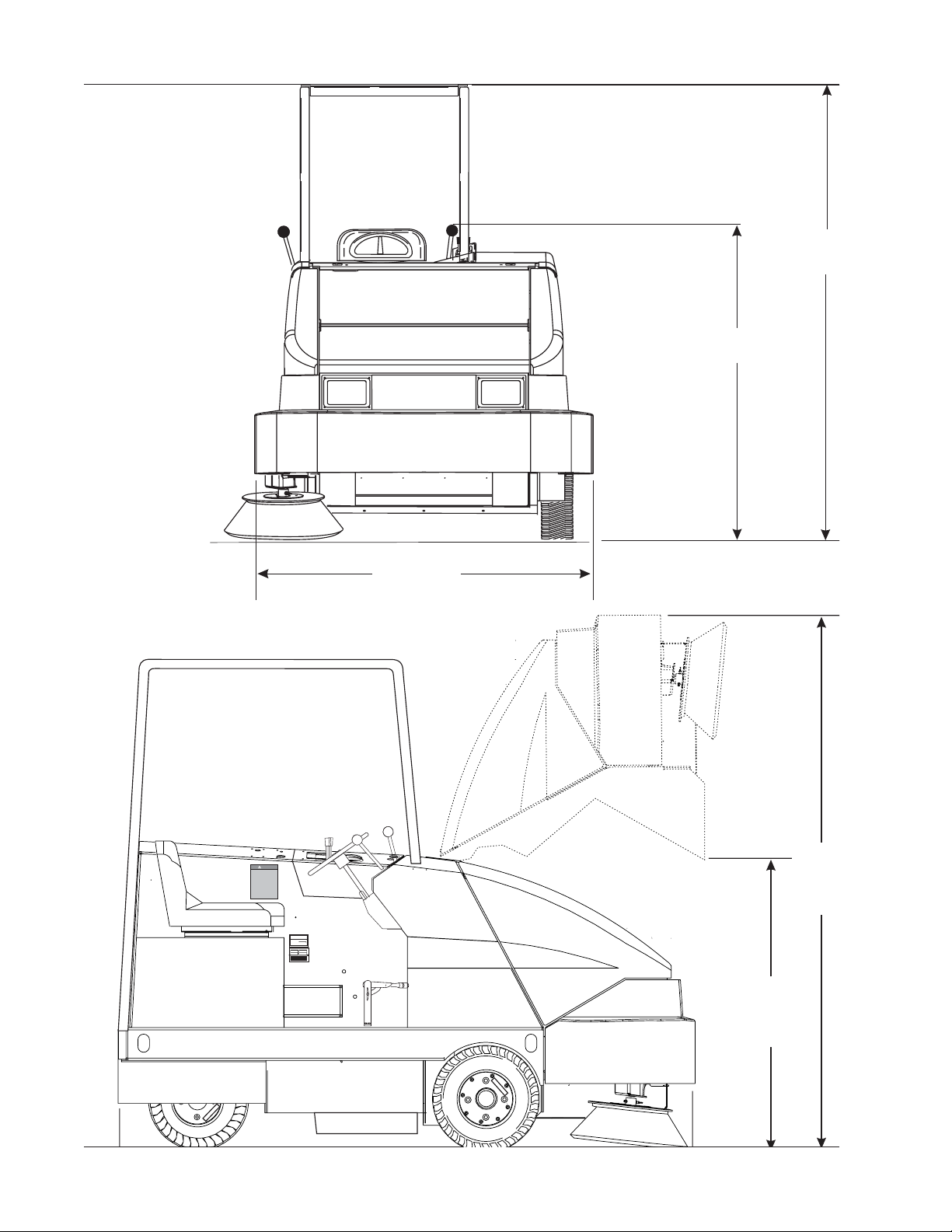
MACHINE DIMENSIONS
53.00"
135 cm
77.7
197
54.75 "
139 cm
WARNING
88.0
223
MODELNO. SERIAL NO.
60.00 "
147 cm
1-8 American-Lincoln
6150
MACHINE PREPARATION
YOUR SWEEPER HAS BEEN SHIPPED COMPLETE, BUT DO NOT ATTEMPT TO OPERATE WITHOUT
READING AND FOLLOWING THESE INSTRUCTIONS.
PREPARATION
1. Uncrate the sweeper and carefully remove packing material.
2. Inspect the battery connections.
3.^ Fill fuel tank with appropriate fuel.
3.* Install motive power batteries. (See Battery Installation Instructions)
4.* Charge batteries using instructions provided with charger. (See Battery Charging Instructions)
WARNING
Risk of personal injury. Never fill fuel tank while engine is running. Always be sure gasoline container and sweeper
are electrically connected prior to pouring fuel. This can easily be done by providing an insulated wire (Perma-
nently attached to the container) with a battery clip attached to the other end.
4.^ Check engine crankcase oil level.
5.^ Check radiator coolant level. Permanent type antifreeze is added at the factory to provide pro tection
to approximately -35° F (-2° C) To retain this level of protection always add 1/2 part water to 1/2
part antifreeze.
6. Check fluid level in hydraulic reservoir which is located in the engine compartment. The hydraulic
reservoir is full when fluid can be seen in the sight glass on the side of the reservoir. To get an accurate
reading the hopper must be in the “DOWN” position. If fluid is required add HYDRAULIC FLUID ONLY.
Use Ford Automatic Transmission Fluid Type “F”.
^For Gas/LP/Diesel Machines Only
*For Battery Machines Only
American-Lincoln 1-9
6150

SAFETY PRECAUTIONS
THE FOLLOWING STATEMENTS ARE USED THROUGHOUT THIS MANUAL AS INDICATED IN THEIR
DESCRIPTIONS:
DANGER
To warn of immediate hazards which will result in severe personal injury or death.
WARNING
To warn of hazards or unsafe practices which could result in severe personal injury or death.
CAUTION
To warn of hazards or unsafe practices which could result in minor personal injury.
ATTENTION
To warn of unsafe practices which could result in extensive equipment damage.
NOTE
To give important information or to warn of unsafe practices which could result in equipment damage.
THE FOLLOWING INFORMATION SIGNALS POTENTIALLY DANGEROUS CONDITIONS TO THE OPERATOR OR EQUIPMENT. READ THIS MANUAL CAREFULLY. KNOW WHEN THESE CONDITIONS CAN EXIST.
THEN, TAKE NECESSARY STEPS TO TRAIN MACHINE OPERATING PERSONNEL.
FOR THE SAFE OPERATION OF THIS MACHINE, READ AND UNDERSTAND ALL WARNINGS,
CAUTIONS AND NOTES.
WARNING
Machines can ignite flammable materials and vapors. Do not use with or near flammables such as: gasoline, grain
dust, solvents and thinners.
WARNING
Heavy machinery. Improper use can cause personal injury.
WARNING
Operate only when lids, doors, and access panels are securely closed.
WARNING
Use care when reversing machine in confined area.
WARNING
When servicing the machine disconnect the battery first to prevent possible injury.
WARNING
When working on the machine, empty hopper, disconnect battery, clear area of people and obstructions, use
additional people and proper procedures when lifting the machine.
WARNING
Always empty the Hopper and Disconnect Battery before doing maintenance.
WARNING
You must have training in the operation of this machine before using it. READ THE INSTRUCTION BOOK.
WARNING
Do not operate this machine unless it is completely assembled.
WARNING
Do not use this machine as a step or furniture.
1-10 American-Lincoln
6150

SAFETY PRECAUTIONS
WARNING
Be careful when operating the machine on a ramp or incline. Always move slowly on a ramp. Do not turn this
machine on a ramp. Do not stop and leave this machine on a ramp.
WARNING
Stop and leave this machine on a level surface. When you stop the machine, put the power switch in the “OFF”
position and Engage the parking brake.
WARNING
To prevent injury, and damage to the machine, do not lift the machine or move it to an edge of a stair or loading
dock.
WARNING
Lead acid batteries generate gases which can cause an explosion. Keep sparks and flames away from batteries.
NO SMOKING. Charge batteries only in area with good ventilation.
WARNING
Always wear eye protection and protective clothing when working near batteries. Remove all jewelry. Do not put
tools or other metal objects across the battery terminals, or the tops of batteries.
WARNING
Maintenance and repairs must be done by authorized personnel only. Tighten all fasteners. Keep adjustments
according to the specifications given in the service manual for the machine. Keep the electrical parts of the
machine dry. For storage, keep the machine in a building.
WARNING
Make sure that all labels, decals, warnings, cautions and instructions are fastened to the machine. Get new labels
and decals from American Lincoln.
WARNING
To maintain stability of this sweeper in normal operation, the counterweights, over-head guard, rear bumper guard
or any similar equipment installed by the manufacturer as original equipment, should never be removed. If it
becomes necessary to remove such equipment for repair or maintenance. This equipment must be reinstalled
before the sweeper is placed back in operation.
WARNING
The hopper could lower unexpectedly and cause personal injury. Engage the hopper safety arm before working
under the hopper.
WEEE Symbol Information
ENGLISH
Correct Disposal of This Product (Waste Electrical & Electronic Equipment)
(Applicable in the European Union and other European countries with separate
collection systems)
This marking, shown on the product or its literature, indicates that it should not be
disposed with other household wastes at the end of its working life. To prevent possible
harm to the environment or human health from uncontrolled waste disposal, please
separate this from other types of wastes and recycle it responsibly to promote the
sustainable reuse of material resources. Household users should contact either the
retailer where they purchased this product, or their local government office, for details
of where and how they can take this item for environmentally safe recycling. Business
users should contact their supplier and check the terms and conditions of the purchase
contract. This product should not be mixed with other commercial wastes for disposal.
American-Lincoln 1-11
6150
SWEEPER CONTROLS/INSTRUMENTS
GLOW
LIGHT
SWITCH
PLUG
SWITCH
LIGHTS
WORK
LIGHT
H
O
U
R
S
0
0
0
0
0
1
/1
0
GLOW
PLUG
MAIN BROOM
CIRCUT BREAKERS
1234
HORN
CHOKE
CHOKE
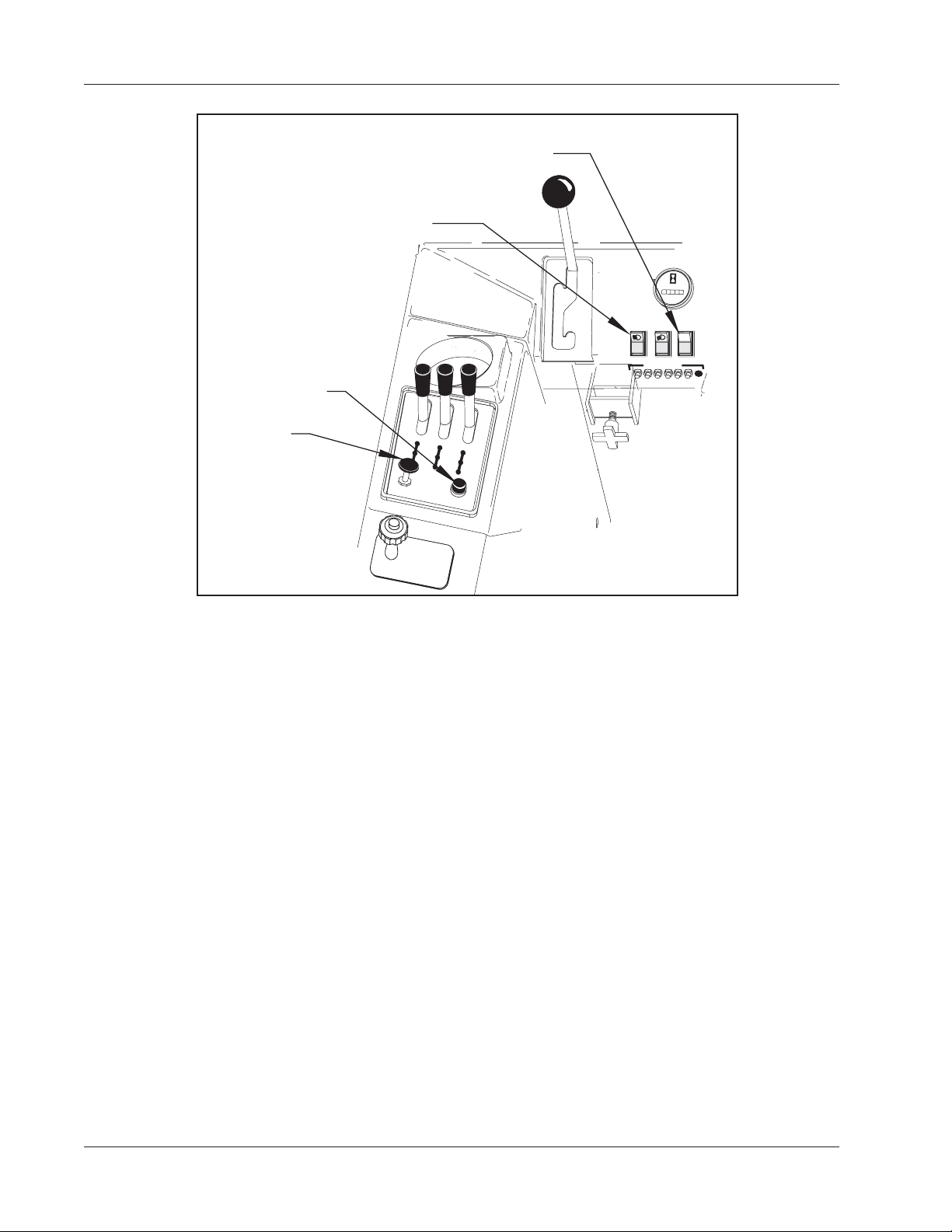
C0701A FIGURE 1
HORN BUTTON
The horn button is located on the left side console next to the choke control. Push the button to sound the horn.
The horn button is always active.
LIGHT SWITCH
The light switch is located on the instrument panel and controls the headlights, taillights and instrument panel
lights. To turn on the lights press the upper portion of the switch. The upper potion of the switch will illuminate to
indicate the lights are “ON”. The light switch is always active.
H
T
T
O
R
HORN
E
L
T
GLOW PLUG SWITCH (Diesel Only)
The glow plug switch is a momentary type rocker switch that is located on the instrument panel and is used to
start the diesel engine. It should be noted that under no circumstances should Ether or other starting aids be
used in conjunction with the glow plugs. To prevent damage to the glow plug switch, do not use for more than 60
seconds. They key switch must be placed in the “ON” position before using the glow plug switch.
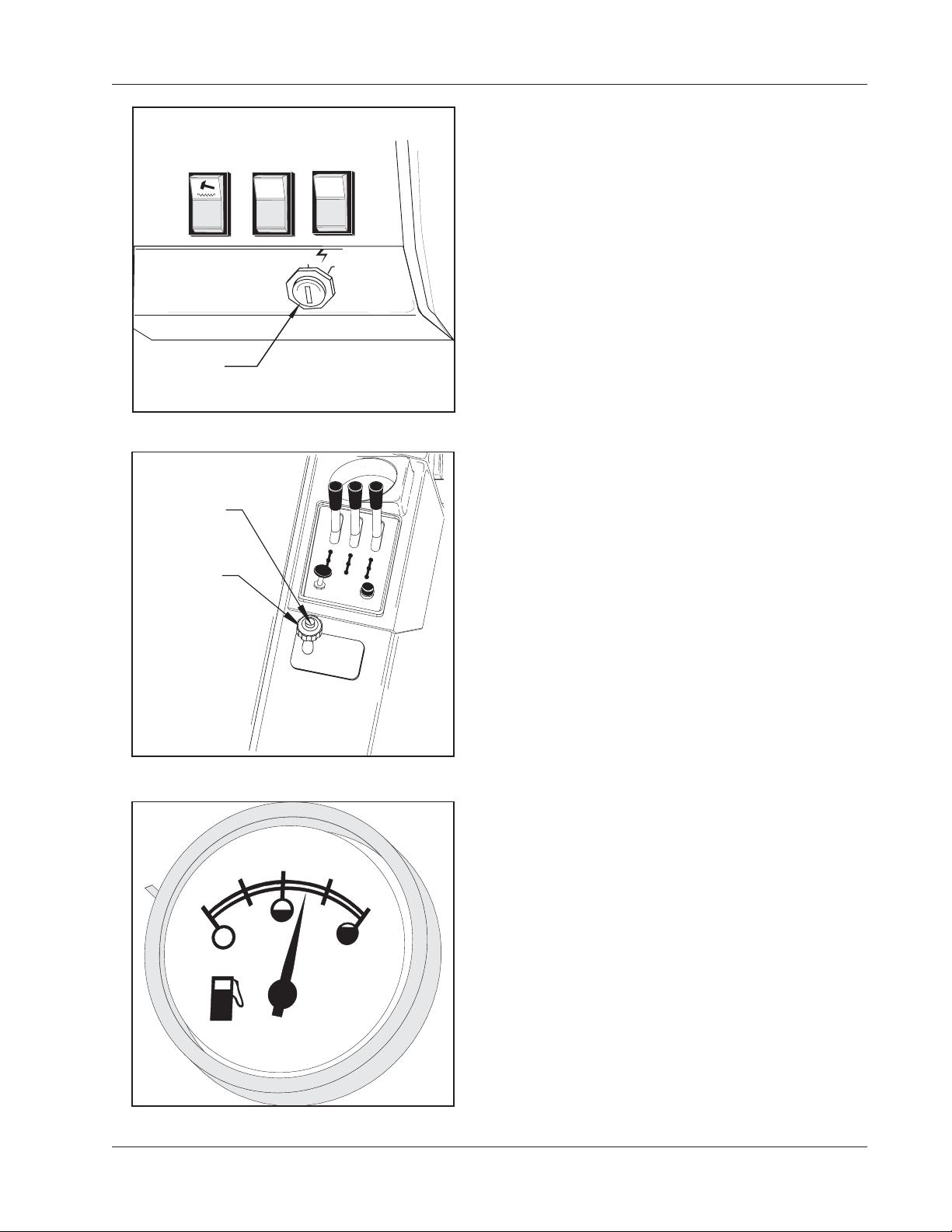
CHOKE CONTROL
The choke control is located on the left side console and is used to aid in starting the engine. The choke
governs the mixture of air and fuel during the combustion cycle of the engine operation. The choke should be
pulled up during the start of the engine and then gradually pushed back down after engine warm up.
To turn on the choke for “Cold” starting, pull “UP” on the control.
To turn off the choke once engine has been started gradually push the control “DOWN”.
1-12 American-Lincoln
6150
C0701-1
C0703/0005
FILTER
SHAKER
KEY
SWITCH
SWEEPER CONTROLS/INSTRUMENTS
KEY SWITCH
The keyed ignition switch is located on the instrument
panel to the right of the steering column. The key switch
is a four position switch that controls power to the
sweeper systems and accessories.
BATTERY POWERED MACHINES
The “O ” position will shut off power to the machine
O
I
propulsion and sweeping systems.
The “I” position provides power to all sweeper systems and
accessories.
GAS/DIESEL/LP POWERED MACHINES
The “O” position will shut off the engine.
C0701-1 FIGURE 2
PUSH BUTTON
TO RELEASE
THROTTLE
C0702 FIGURE 3
1/2
The “I” position provides power to all sweeper systems and
accessories.
THROTTLE
The engine speed is controlled by a locking push-pull
control which is located on the operator’s compartment
side console.
C
H
O
K
E
H
O
R
N
The position of the throttle determines the operating speed
of the engine. The position is variable from idle to max
engine speed and may be adjusted to suit operating
conditions.
THROTTLE
The locking feature of the engine throttle control consists
of a rubberized push button that unlocks the control for
adjustment.
Push down on the button while positioning the control to
the desired setting, then release the button to unlock the
throttle in place.
Pull up on the throttle to increase engine speed.
Push down on the throttle to decrease engine speed.
0
4/4
FUEL GAUGE
The fuel gauge is located on the instrument panel and
indicates the level of fuel in the tank. The fuel gauge is
powered by the key switch. The key switch must be in
the “I” position for the fuel gauge to work. The fuel gauge
is not included on machines that use Battery or Liquid
FUEL
Propane fuel.
C0703 FIGURE 4
American-Lincoln 1-13
6150
C
C-0704
R
OLES
SWEEPER CONTROLS/INSTRUCTIONS
1/2
4/4
MAINBROOM
FOOT
BRAKE
LIGHTS
CIRCUTBREAKERS
1234
H
O
U
R
S
0
0
0
0
0
1
/
1
0
WORK
GLOW
LIGHT
PLUG
5 6 OPTION
American-Lincoln
APPLY
BRAKE
TO
0
FUEL
FILTER
DUST
ENGINE
SHAKER
CONTROL
SPEED
2
1
SIDEBROOM
IDLE
OFF
ACC
IGN/ON
START
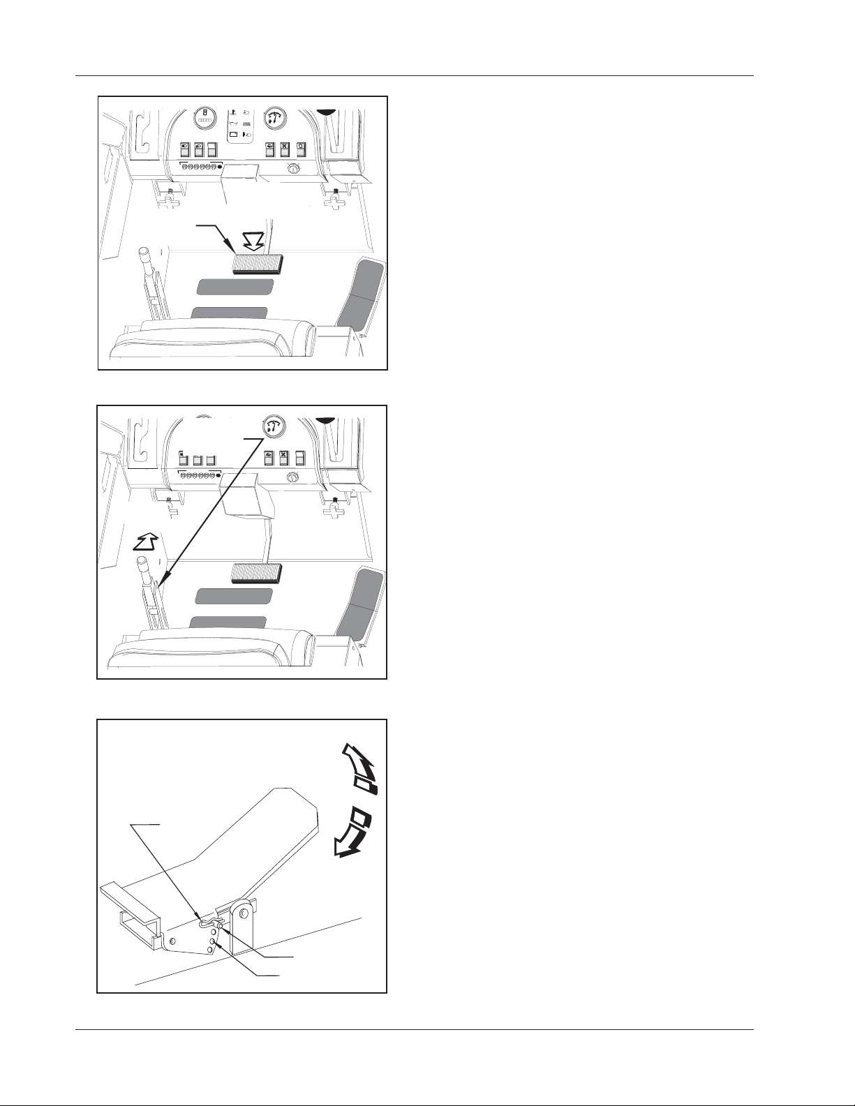
FOOT BRAKE
The foot brake pedal is located on the floor of the
operator’s compartment to the left of the directional
control pedal.
To stop, apply foot pressure to the brake pedal.
PARKING BRAKE
The parking brake lever is located on the operator’s
compartment left side panel near the floor. When engaged
the parking brake “locks” the foot pedal in the down
position.
-0704
C0704 FIGURE 5
H
O
U
R
S
0
0
0
0
0
1
/10
PARKING
WORK
GLOW
LIGHTS
LIGHT
PLUG
BRAKE
CIRCUTBREAKERS
American-Lincoln
5 6 OPTION
C-0705
MAINBROOM
TO
RELEASE
BRAKE
1234
C0705 FIGURE 6
- To engage the parking brake, place the lever in
the upright position.
- To disengage the parking brake, move the lever for
ward.
- To Adjust The Parking brake “Grab” Turn the knob on
the top of the lever.
1/2
4/4
0
FUEL
FILTER
DUST
SHAKER
CONTROL
SIDEBROOM
O
I
- To increase “Grab” Turn the knob in a clockwise
direction.
- To decrease “Grab” Turn the knob in a counterclockwise direction.
FOOT PEDAL
The Foot Pedal is located on the floor of operator’s
compartment to the right of the brake pedal. The foot
pedal provides control of direction/speed and has an
automatic safety feature that limits foot pedal travel while
the hopper is raised. The pedal height is adjustable to
provide for operator comfort.
TO GO FORWARD: Place pressure on the upper portion
of the pedal. Speed increases when additional pressure is
placed on the pedal.
TO GO BACKWARD: Put pressure on the lower portion of
EVERSE
the pedal. Speed increases when additional pressure is
placed on the pedal.
-To increase braking action while sweeper is moving
NEUTRAL
forward, gently put pressure on the lower portion of the
pedal.
HAIRPIN
COTTER
FORWARD
-To Increase braking action while traveling in reverse,
gently put pressure on the upper portion of the pedal.
To adjust the foot pedal height for operator comfort
1. Remove the hairpin cotter from the adjustment pin.
2. Remove the adjustment pin from the foot pedal
assembly.
3. Align the holes in the lower bracket with one of the
C-0706
C0706 FIGURE 7
ADJUSTMENT
PIN
ADJUSTMENT
H
four adjustment holes on the foot pedal to set the
foot pedal height.
4. With the holes aligned at the desired height, insert
the adjustment pin
5. Reinstall the hairpin cotter.
1-14 American-Lincoln
6150
WARNING
ENGINE
SWEEPER CONTROLS/INSTRUMENTS
HOPPER
DUMP DOOR
LIGHT
DUST
CONTROL
LIGHT
HOPPER
TEMP.
LIGHT
ENGINE OIL
PRESSURE
LIGHT
CHARGING
SYSTEM
LIGHT
TEMP.
LIGHT
LIGHTS
1234
C-0707-1
HOURS
00000
WORK
LIGHT
CIRCUT BREAKERS
1
/
1
0
GLOW
PLUG
5 678
BANK
1/2
4/4
0
FUEL
-
+
FILTER
SHAKER
DUST
CONTROL
O
I
C0707-1 FIGURE 8
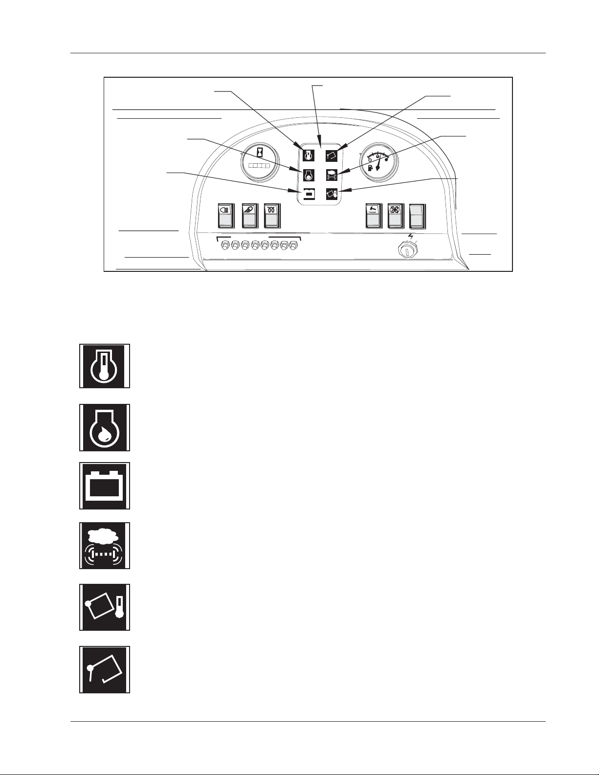
WARNING BANK
The Warning Bank is located on the instrument panel and provides the operator with six fault/status indicators
for engine and sweeper systems. The Operator should monitor the indicators while sweeping. It is very important
that the operator be familiar with the meaning of each indicator.
ENGINE TEMP LIGHT
The engine temperature light illuminates to indicate an engine cooling system fault. When this
occurs the operator must turn off the sweeper immediately and have the cooling system
serviced by a qualified service technician.
ENGINE OIL PRESSURE LIGHT
When the oil pressure drops below approximately 5 psi an automatic protection circuit shuts
down the engine and illuminates the light to indicate low engine oil pressure. When this occurs
have the sweeper serviced by a qualified service technician.
CHARGING SYSTEM LIGHT
-
+
The charging system light illuminates to indicate a charging system fault. When this occurs
the sweeper charging system is not working properly and must be serviced by a qualified
service technician.
DUST CONTROL LIGHT
The Dust Control Light Illuminates to indicate that the dust control filter is clogged. When this
occurs, stop sweeping and use the filter shaker to clear dirt and debris from the filter. After
using the filter shaker continue sweeping.
HOPPER TEMPERATURE LIGHT
When the temperature of the air moving through the dust control system in the hopper ex
ceeds 140° F, an automatic protection feature shuts down the dust control fan and illuminates
the hopper temperature light. When this occurs shut down the sweeper and carefully investi
gate for a possible fire in the hopper. The temperature switch must be manually reset.
DUMP DOOR LIGHT
The dump door light will illuminate when the dump door is not fully open. The light warns the
operator to open the hopper dump door completely before sweeping. Do not sweep when the
light is illuminated.
American-Lincoln 1-15
6150
SEAT
SWEEPER CONTROLS/INSTRUMENTS
POSITION
ADJUSTMENT
LEVER
TO
LOCK
C-0714
C0714 FIGURE 9
TURN SIGNAL
SWITCH
00000
WORK
LIGHTS
LIGHT
TO SIGNAL
RIGHT TURN
TO TURN
ON 4-WAY
FLASHER
TO SIGNAL
LEFT TURN
HOURS
1
/
1
GLOW
PLUG
0
4-WAY FLASHER
American-Lincoln
TO ADJUST
SWITCH
0
SEAT POSITION ADJUSTMENT
The seat adjustment lever is located on the right side of
the seat base. The lever is spring loaded to the “LOCK”
position.
To adjust the seat, push “FORWARD” on the lever and
move seat to desired position then release the lever to
“LOCK” the seat in place.
TURN SIGNALS - 4 WAY (OPTION)
The turn signal switch is located on the steering column
and functions the same as a typical automotive turn signal.
The operator must return the lever to the centered position
after the turn has been completed.
1/2
4/4
FUEL
-To signal a right hand turn move the lever to the “FORWARD” position.
-To signal a left hand turn position the lever to the “BACKWARD” position.
-To use the 4-way Flashers pull out on the turn signal lever.
C-0715
BACK UP ALARM (OPTION)
The backup alarm is activated by a switch in the foot pedal
C0715 FIGURE 10
and automatically emits a loud audible noise when the
machine is driven in reverse.
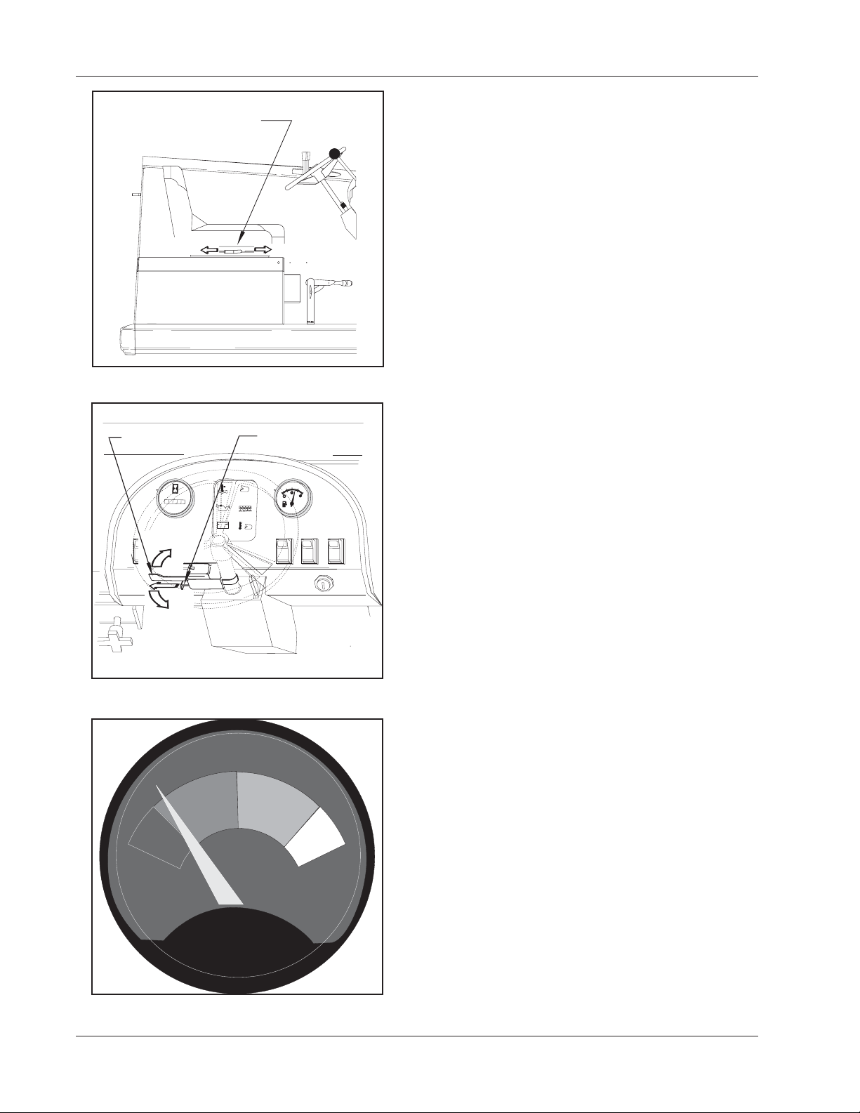
BATTERY CONDITION METER (Battery Power Only)
The battery condition meter is located on the right side of
the instrument panel. The condition meter indicates the
level of charge in the batteries. The batteries are sufficiently charges when the needle stays in the green area
on the gauge while the machine is being operated.
Charge the batteries when the needle drops into the red
zone while operating the machine,
Do not operate the machine if the needle stays in the red
zone. Operating the sweeper with discharges batteries
with degrade battery life.
C-0718
C0718 FIGURE 11
1-16 American-Lincoln
6150
FILTER
BROOMS
SHAKER
C0717-1
FILTER
SHAKER
DUST
CONTROL
O
C0717-1 FIGURE 12
DUST
CONTROL
FILTER
SHAKER
DUST
CONTROL
SWEEPER CONTROLS/INSTRUMENTS
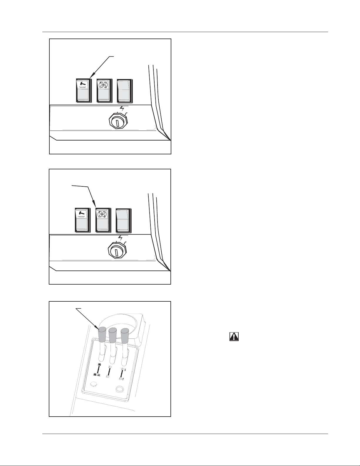
FILTER SHAKER SWITCH
The filter shaker switch is located on the instrument panel
below the fuel gauge. This is a momentary switch that will
activate the filter shaker motors for 20 to 30 seconds to
clear the dust control filter. The impeller fan will stop when
the filter shaker has been activated.
The filter shaker will only operate with the hopper in the
“DOWN” position. Use the filter shaker to clear the filter
when the dust control light on the warning bank illuminates
I
and just before dumping the hopper.
To activate the filter shaker press the upper portion of the
filter shaker switch momentarily and release. The filter
shaker will operate for 20 to 30 seconds.
DUST CONTROL SWITCH
The dust control is a two position switch that is located on
the instrument panel next to the engine speed switch. The
switch controls the vacuum fan in the dust control system.
To turn on the dust control system for “NORMAL” Sweeping, press on the top portion of the switch.
O
C0716-1
C0716-1 FIGURE 13
CONTROL
LEVER
O
N
OPEN
O
N
BROOMS
C
L
O
S
E
H
O
RAISE
P
P
E
R
H
D
O
O
P
O
CHOKE
C-0719
R
HORN
To Turn off the dust control system for sweeping in wet
I
conditions, press on the lower portion of the switch. This
will prevent the filter from being damaged by water pickup
while sweeping.
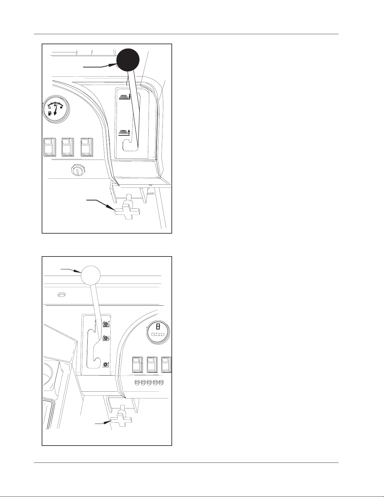
BROOMS CONTROL LEVER
The brooms control lever is located on the operator’s
compartment center console. The lever is a three position
hydraulic valve that controls hydraulic power to the main
broom and side broom.
WARNING
To prevent injury, Do not turn on the brooms
with the hopper raised.
LO
W
ER
To turn on the main broom only, move the lever to the
forward position.
P
E
R
To turn on the main broom and the side broom, move the
lever fully backwards.
To turn off the brooms and provide hydraulic power to the
hopper lift system place the lever in the center position.
C0719 FIGURE 14
American-Lincoln 1-17
6150
SWEEPER CONTROLS/INSTRUMENTS
SIDE BROOM
LEVER
1/2
4/4
0
FUEL
SIDE BROOM
ADJUSTMENT
DOWN
UP
SIDE BROOM
SIDE BROOM LEVER
The side broom lever is located on the right side of the
instrument panel. The side broom lever raises and lowers
the side broom. Use the brooms lever on the operator’s
center console to turn on the side broom.
To raise the side broom, pull the lever back into the “UP”
position.
To lower the side broom, move the lever out of the
detented “UP” position and move it forward to the “DOWN”
position.
SIDE BROOM ADJUSTMENT
The side broom lever has an adjustment for changing the
sweep height to compensate for broom wear. The side
broom adjustment is located under the right side of the
instrument panel.
To Adjust the side broom height turn the threaded knob.
C0720 FIGURE 15
MAIN BROOM
LEVER
FLOAT
SWEEP
UP
MAIN BROOM
MAIN BROOM
ADJUSTMENT
C-0721
C0721 FIGURE 16
LIGHTS
WORK
LIGHT
MAIN BROOM LEVER
The main broom lever is located on the left side of the
instrument panel. The main broom lever has three positions and controls the main broom sweep height. Use the
brooms lever on the operator’s center console to turn on
the main broom.
To lower the main broom, grasp the lever and move it to
the left out of the “UP” position and place in the “SWEEP”
or “FLOAT” position.
H
O
U
R
S
0
0
0
0
0
1
/
1
0
The “SWEEP” position is used for normal sweeping and
should be used under most sweeping conditions.
GLOW
PLUG
The “FLOAT” position is used for sweeping very uneven
surfaces only. Using the Float position will cause premature wear on the main broom if used under normal operating conditions for extended periods of time.
MAIN BROOM ADJUSTMENT
The main broom lever has an adjustment for changing the
sweep height to compensate for broom wear. The main
broom adjustment is located under the left side of the
instrument panel.
To Adjust the main broom height turn the threaded knob.
1-18 American-Lincoln
6150

S
SWEEPER CONTROLS/INSTRUMENTS
ON
OPEN
ON
B
CLOSE
R
O
O
M
S
H
O
P
P
E
R
H
D
O
O
C-0722
C
H
R
O
K
E
H
C0722 FIGURE 17
HOPPER
LIFT
LEVER
O
N
OPEN
O
N
B
C
R
L
O
O
S
O
E
M
S
H
O
P
P
ER
H
D
O
O
C-0723
C
H
R
O
K
E
H
C0723 FIGURE 18
O
O
O
RAISE
O
R
P
PPE
R
LOWER
A
IS
P
R
LOWER
HOPPER
DOOR
LEVER
E
E
R
N
R
N
DEBRI
DOOR
HOPPER DOOR LEVER
The hopper door lever is located on the operator’s compartment center console and is used to close and open
the hopper dump door. The lever is a three position
hydraulic valve that is spring loaded to the center position
which “HOLDS” the hopper door in position.
NOTE
To provide hydraulic power to the hopper controls, the
broom control lever must be in the center “Neutral”
Position
To ensure the door is fully open while sweeping, monitor
the Hopper Dump Door light on the Warning Bank . The
light will illuminate when the door is not fully open.
To open the hopper dump door for sweeping or dumping,
push the lever forward in the “OPEN” direction until the
hopper dump door light goes out.
To close the hopper dump door for dumping or transporting, pull the lever fully back in the “CLOSE” direction and
hold for 3 seconds or until you hear the door close.
HOPPER LIFT LEVER
The hopper lift lever is located on the operator’s compartment center console. The lever is a three position hydraulic valve that controls the operation of the hopper lift
system. The lever is spring loaded to the center position
which stops hopper movement and “HOLDS” the hopper at
the present position.
NOTE
To provide hydraulic power to the hopper controls, the
broom control lever must be in the center “Neutral”
Position
To raise the hopper for dumping, move the lever back to
the “RAISE” position and hold until the hopper reaches the
desired height, then release.
WARNING
To prevent injury, Do not turn on the brooms with the hopper
raised.
To lower the hopper after dumping, move the lever forward
to the “LOWER” position until the hopper is fully lowered
and seated in the sweeper, then release.
DEBRIS DOOR
The hopper debris door provides the operator with easy
access to the hopper debris compartment for refuse
C-0724
disposal or visual inspection of the removable filter baffle
and hopper debris compartment. The debris door must be
C0724 FIGURE 19
closed while sweeping. Failure to close the door completely will cause poor dust control while sweeping.
American-Lincoln 1-19
6150

T
SWEEPER CONTROLS/INSTRUMENTS
DUST
BAFFLE
THREADED
KNOB
DUST BAFFLE
The dust baffle is located in the hopper and may be
removed for cleaning. The dust baffle is mounted to the
hopper with two threaded knobs for easy removal.
The debris door must be opened to gain access to the
dust baffle.
Remove and clean the dust baffle when debris becomes
lodged in the baffle passages.
To remove the baffle, turn the two threaded knobs counterclockwise and lift the baffle off the studs.
C-0726
C0726 FIGURE 20
HOPPER
SAFETY ARM
WARNING
MODELNO. SERIALNO.
6150
C-0727
C0727 FIGURE 21
TO
ENGAGE
DEBRIS
COMPARTMEN
COVER
HAND
HOLD
To install the baffle, position the baffle on the studs and
turn the two threaded knobs clockwise.
HOPPER SAFETY ARM
The hopper safety arm is located near the right front wheel
well. The safety arm will prevent the hopper from dropping
unexpectedly during service/maintenance.
WARNING
The Hopper Could Drop Unexpectedly And Cause Injury.
Engage The Safety Arm Before Working Under Hopper.
WARNING
For Safety Always Empty Hopper Before Servicing.
TO ENGAGE THE SAFETY ARM:
1. Empty hopper.
2. Set the parking brake.
3. Raise the hopper.
4. Lift safety arm to engage the slot on the hopper
frame.
5. When work has been completed, replace the safety
arm to the stowed position.
HOPPER FILTER COMPARTMENT COVER
The Hopper Filter Compartment Cover is located on the
top of the hopper and opens forward for access to the filter
compartment for service and inspection of the dust control
filter and operational hopper temp sensor.
Use the hand hold provided to open the cover.
Inspect the cover gaskets daily. Replace any cover
gaskets that show signs of deterioration. Failure to
maintain the gaskets in serviceable condition will degrade
dust control at the floor and will result in less than minimal
sweeping performance.
C-0776
C0776 FIGURE 22
1-20 American-Lincoln
6150

SWEEPER CONTROLS/INSTRUMENTS
TURN LATCH
TO RELEASE
FILTER
PANEL
C-0777
C0777 FIGURE 23
HOPPER
TEMPERATURE
SENSOR
RESET
BUTTON
LIFT
FRAME TO
REMOVE
FILTER
PUSH
TO
RESET
FILTER
PANEL
LATCH
FILTER PANEL LATCH
The filter panel is located in the hopper filter compartment
and will need to be removed periodically for cleaning or
replacement. Removal of the filter panel requires no tools.
The hopper cover must be opened to gain access to the
filter compartment. The panel filter is held in place by a
hinged frame and latch.
To remove the panel filter, turn the know counter clockwise
and lift the hinged frame.
The panel filter can now be lifted out and cleaned or
replaced. (See Filter Cleaning Instructions in the Manual.)
To install the replacement panel filter, lower the frame and
turn the knob clockwise to lock the filter in place.
HOPPER TEMP SENSOR (OPTION)
The temp sensor switch monitors the hopper air temperature near the vac fan. When the temperature of the air
moving through the hopper exceeds 140ºF the switch trips
which turns off the dust control fan and illuminates the
hopper temp light on the warning bank.
The hopper temp sensor is a resetable thermal switch
which is locates in the hopper filter compartment near the
vacuum fan intake.
C0778 FIGURE 24
-
ENGINE
COMPARTMENT
LATCH
LIFTTOOPEN
When the hopper temp light illuminates, carefully investigate for a possible fire in the hopper.
The sensor will not reset until the temperature in the
hopper has dropped below 133ºF.
To reset the temp sensor, press the reset button.
ENGINE COMPARTMENT LATCH
The engine cover encloses the entire engine, radiator and
hydraulic reservoir assembly. The cover can be swung
open to allow easy access to the engine and hydraulics
for service or inspection.
WARNING
Operate Only When Lids, Doors, And Access Panels Are
Securely Closed.
American-Lincoln
To open the cover, lift the cover latch lever up. Swing the
cover open.
The cover will latch automatically when the cover is
closed. After closing the engine cover, check to be certain
the latch has fully engaged.
C-0779
C0779 FIGURE 25
American-Lincoln 1-21
6150

SWEEPER CONTROLS/INSTRUMENTS
HYDRAULIC
SIGHT
GAUGE
C-0728
C0728 FIGURE 26
American-Lincoln
MAIN BROOM
COMPARTMENT
LATCH
HYDRAULIC RESERVOIR LEVEL SIGHT GAUGE
The sight gauge is located on the side of the hydraulic
reservoir in the engine compartment. The sight gauge is
used to indicate the level of fluid in the reservoir. Fluid level
must be visible in the sight gauge when the hopper is in
the down position.
MAIN BROOM COMPARTMENT DOORS
The main broom compartment doors are located behind
the front tires on both sides of the sweeper. The doors
provide access to the main broom for service or inspection.
WARNING
Operate Only When Lids, Doors, And Access Panels Are
Securely Closed.
Open the right side door to remove or replace the main
broom. The right side door is an integral part of the main
broom drive system and must be closed for operation.
Open the left side broom door for inspection. Check the
drive hub for banding and shrink wrap which have a
tendency to get tangled in the broom driver.
To open the main broom door, reach inside the hole in the
door and lift up on the latch handle.
The door latch will automatically engage when the door is
closed.
C-0729
LIFT TO OPEN
C0729 FIGURE 27
WARNING
American-Lincoln
c0731/0005
C0731 FIGURE 28
SEAT COMPARTMENT COVER
The seat compartment cover opens to allow easy access
to various components which will need to be inspected or
serviced periodically. The cover opens forward and has a
safety latch to hold the cover in the open position.
WARNING
Lead acid batteries generate gases which can cause an
explosion. Keep sparks and flames away from batteries.
NO SMOKING. Charge batteries only in area with good
ventilation and keep the seat cover open to vent explosive
hydrogen gas.
MODELNO. SERIALNO.
On battery powered machines the compartment below the
seat contains the charging connector for the batteries.
Use the safety latch to hold the cover open while charging
the batteries.
On Gas/Diesel/LP powered machines the seat compartment contains the fuel tank.
1-22 American-Lincoln
6150

LIFT TO HOLD
LIFT TO HOLD
SEAT COVER
OPEN
SEAT COVER
OPEN
C0732
C0732 FIGURE 29
BATTERY
CHARGING
CONNECTOR
TRABA DEL COMPARTIMIENTO
DEL ASIENTO
TO DISCONNECT
BATTERIES
FOR CHARGING
SWEEPER CONTROLS/INSTRUMENTS
SEAT COMPARTMENT LATCH
The seat compartment latch is located under the seat
compartment cover and is used to hold the cover open
while charging the batteries.
To hold the seat compartment cover open, lift the latch to
the vertical position and release the cover to rest on the
latch.
BATTERY CHARGING CONNECTOR
The batteries on battery powered machines are connected
to the machine through a heavy duty two conductor
connector. The connector allows an easy method of
disconnecting power to the machine for service or charging of the batteries.
C0730 FIGURE 30
Plug the charger into the connector to charge the batteries.
WARNING
Disconnecting the battery connector with the key switch in
the “I” position will cause sparks that could ignite explosive
hydrogen gas generated by the batteries. To prevent
serious injury or possible property damage, turn key switch
to “O” position before disconnecting battery cable from
machine charging or service.
American-Lincoln 1-23
6150

HELPFUL HINTS FOR SWEEPING
SIDE AISLES
MAIN AISLE
P4134/0001
P4134 FIGURE 31
HOW TO SWEEP
The sweeper is intended for use on hard relatively flat surfaces such as cement, asphalt, and wood block floors.
Exercise care when maneuvering to keep wheels from dropping off curbs or into pot holes. Do not sweep over
obstructions.
WARNING
Do Not Turn The Steering Wheel Sharply When The Machine Is In Motion. The Sweeper Is Very Responsive To
Movement Of The Steering Wheel. Do Not Make Sudden Turns.
The sweeper is designated for dry sweeping conditions. Wet clay and muddy type material will adhere to
surface of sweeping chamber and hopper. Sweeping performance will degrade if these surfaces are not kept
clean. Large heavy objects such as bricks, large stone, and iron parts should not be swept. Damage to the
main broom or other sweeping system components is possible. String, rope, wire or metal strapping longer than
18 inches should not be swept. These items have a tendency to wrap around moving parts. This can cause
damage or degrade sweeping performance.
SWEEPING GUIDELINES
In actual sweeping, there is no single pattern that can be set forth in this manual. Each installation has its own
conditions, and the operator can readily set his own pattern using these guidelines.
-Pick up large debris before sweeping with machine.
-Use the machine to sweep debris from narrow aisles into main aisle.
-After the machine has made a sweeping run, push the filter shaker control button for 20 to 30 seconds, the filter
shakers will unload accumulated dust from the filter media.
-Sweep debris from main aisle.
-Overlap of broom paths when sweeping. This will eliminate leaving dirty patches.
-Empty hopper when the sweeper leaves debris, while sweeping
-Sweep in straight paths. Do not bump posts. Do not scrape the sides of the machine.
NOTE
Replace main broom when bristles are worn to 1.75 inch (3.5 cm) length. To order replacement brooms, see MAIN
BROOM section of this manual. Replace side broom when bristles fail to sweep debris into the path of the main
broom. To order replacement brooms, see SIDE BROOM section of this manual.
SWEEPING VARIOUS TYPES OF DEBRIS
For heavy sand, dirt, or excessive scattered debris, travel slowly with machine to allow main broom to deliver
best results. Do not expect a completely clean surface on the first pass under these conditions. Sometimes it
is necessary to have extra broom pressure where debris is excessively heavy. See “Main Broom Adjustment” for
information on adjusting broom to a “heavy” sweeping pattern. Material that adheres to the sweeping surface:
This type of wet or sticky material will require more broom pressure.
1-24 American-Lincoln
6150

OPERATING INSTRUCTIONS
BATTERY MACHINE OPERATION
Charge the batteries after operating the machine. See the battery charging instructions in the is manual. Use
the pre-start check-list and follow the service chart for daily check points. Read and follow the safety precautions to assure safe, trouble free operation.
WARNING
Lead acid batteries generate gases which can cause an explosion. Keep sparks and flames away from batteries.
NO SMOKING. Charge batteries only in area with good ventilation and keep the seat cover open to vent explosive
hydrogen gas.
WARNING
Always wear eye protection and protective clothing when working near batteries. Remove all jewelry. Do not put
tools or other metal objects across the battery terminals or the tops of the batteries.
GAS/LP/MACHINE OPERATION
See the LP instructions in this manual for fueling and service instructions on the LP fuel system and replacement of tanks. Use the pre-start check-list and follow the service chart for daily check points. Read and follow
the safety precautions to assure safe, trouble free operation. Gasoline powered machines use regular grade
unleaded gasoline. Turn the engine off before dispensing fuel into the gasoline powered machine.
WARNING
To prevent possible fire: Never fill fuel tank while engine is running. Always be sure gasoline container and
sweeper are electrically grounded before dispensing gas. This can be done by permanently attaching an insulated
wire with a battery clip on the end to the gasoline container.
WARNING
All internal combustion engines give off harmful fumes and gases while running. Do not start or run the engine in
an enclosed area where the exhaust gases can accumulate. Avoid breathing these gases as they contain poison-
ous carbon monoxide which can endanger your health or life if inhaled steadily for even a few minutes.
WARNING
Check for gas odor before and during starting operations. If gas odor is noticed, stop and check for leaks or
component malfunctions in the fuel system. Check fuel supply hoses for proper connection and signs of abrasion.
Do not start engine when gas odor is present.
WARNING
Keep cigarettes, sparks, and open flame away when working on LP equipment, use caution when inspecting for
gas leaks or when LP tanks are present.
WARNING
Do not run engine in an enclosed area. Exhaust gases contain carbon monoxide, an odorless and deadly poison.
Do not operate the engine without adequate ventilation.
American-Lincoln 1-25
6150

OPERATING INSTRUCTIONS
BEFORE STARTING
1. Set Parking Brake.
2. Make sure all controls are in the “Off” position.
3. Be sure accelerator and directional control pedal is in neutral.
PRE-START CHECK LIST
Before starting the engine, perform these pre-start checks.
1. Check engine air filter element indicator.
2. Check engine oil level.
3. Check radiator coolant level.
4. Check hydraulic fluid level.
5. Check fuel level.
6. Check all systems for leaks.
7. Check brakes and controls for proper operation.
8. Check broom patterns
9. Check to ensure that all covers, panels and access doors are securely closed.
NOTE
When Machine Has Been Stored In Below Freezing Temperatures, Run Engine At The “1” (low) Speed Setting With
Machine Standing Still For 5 To 10 Minutes To Warm Engine And Hydraulic Oil.
TO START BATTERY MACHINES
Starting the battery powered models is accomplished by turning the key switch to the “I” (on) position. It is
important to note that the batteries should be fully charged and serviced prior to using the machine.
TO CHARGE BATTERIES
Charge the batteries at the end of each day or when the battery condition meter indicates low battery voltage.
The batteries need to be charged when the needle stays in the “red” zone while the machine is being operated.
When charging batteries, only use the quick disconnect provided ensure correct polarity. Follow the “Battery
Charging Instructions” provided in the service section of this manual.
TO START GAS ENGINE
Use the choke in extremely cold temperatures, (under 32 F. or 0 C.),
1. Pull choke if needed.
2. Set the engine speed switch to the “1” (low) Speed setting.
3. Turn key to “START” position until engine starts, then release. (The key switch will return to the “ON”
position.)
4. Push in choke after engine starts running (If used).
TO START PROPANE ENGINE
Perform these checks in addition to the Pre-Start check list.
1. Check connections for leaks
2. Open the LP storage tank valve.
3. Check the regulator. Momentarily press fuel primer on the regulator cover to bleed air out of the
system.
4. Set the engine speed switch to the “IDLE” (low) Speed setting.
5. Turn key to “START” position until engine starts, then release. (The key switch will return to the “ON”
position.)
1-26 American-Lincoln
6150

OPERATING INSTRUCTIONS
TO START DIESEL ENGINE
When starting the diesel engine, it should be noted that under no circumstances should Ether or any other
starting fluids be used in conjunction with the glow plugs. Do not use the glow plugs for more than 60 seconds
at a time or damage to the plugs may result. They key switch must be placed in the “ON” position before using
the glow plug switch.
1. Perform the Pre-Start checks found previously in this manual.
2. Turn the ignition switch to the “ON” position and place the engine speed switch to the high speed (2)
position.
3. Push and hold the glow plug switch for approximately 30 seconds. Under cold starting conditions, the
glow plug switch may be held longer but do not hold the switch for more than 60 seconds to prevent
damage to the glow plugs.
4. Turn the key switch to the start position and hold until engine starts. If the engine does not start
immediately, release the key switch after 15 seconds to prevent damage to the starter.
5. Release the glow plug switch when the engine starts.
TO DRIVE SWEEPER FOR TRANSPORT
1. Ensure the main broom lever and the side broom lever are in “UP” position with all other sweeping
controls in the “OFF” position.
2. Release the parking brake.
3. Place the engine speed switch in the “1” or ”2" position.
4. Push forward on the foot pedal to start the sweeper moving.
5. Vary your foot pressure on the pedal to obtain the desired speed.
6. To stop, allow the foot pedal to return to the centered position. (Pedal will return to neutral when pressure
is released)
WARNING
Do Not Turn The Steering Wheel Sharply When The Machine Is In Motion. The Sweeper Is Very Responsive To
Movement Of The Steering Wheel. Do Not Make Sudden Turns.
WARNING
Machines Can Ignite Flammable Materials And Vapors. Do Not Use With Or Near Flammables Such As: Gasoline,
Grain Dust, Solvents And Thinners.
TO SWEEP WITH THE MACHINE
1. Move the broom control lever to the “ON” position.
2. Lower the side and main broom to the floor. (The main broom control may be placed in either the “FLOAT”
or “SWEEP” position).
3. Press the Dust Control Switch to the “ON” position.
4. Push forward on directional control pedal to place machine in motion.
5. Vary foot pressure on the directional control pedal to obtain desired travel speed.
6. Read the “Helpful Hints for Sweeping” in this manual for tips on maximizing sweeping performance.
WARNING
Stop And Leave This Machine On A Level Surface. When You Stop The Machine, Put The Key Switch In The “OFF”
Position And Engage The Parking Brake.
TO STOP SWEEPING
1. Allow directional control pedal to return to neutral (centered) position. (Pedal will automatically return to
neutral when foot pressure is released.)
2. Depress the foot brake.
3. Press the Dust Control Switch to the “OFF” position..
4. Place the broom controls (Side and Main) in the “UP” position.
5. Move the Broom Control lever to the center “OFF” position.
6. Push engine speed switch to the “IDLE” position.
7. Set parking brake.
American-Lincoln 1-27
6150

OPERATING INSTRUCTIONS
TO EMPTY DEBRIS HOPPER
1. Press the engine speed switch to the “1” (Normal) or ”2" (High) position.
2. Engage parking brake.
3. Move the Hopper Dump door lever to the “CLOSE” Position until door is closed.
4. Move the hopper lift lever to the “RAISE” position until the hopper reaches the desired height.
5. Disengage Parking Brake.
6. Drive forward slowly with the hopper raised to clear refuse container before opening the hopper dump
door.
7. Engage Parking Brake.
8. Push the hopper dump door lever forward to the “OPEN” position. This will allow debris in the hopper to
fall out into the refuse container.
9. Move the hopper dump door lever to the “CLOSE” Position until door is closed.
10. Disengage Parking Brake. •
11. Drive in reverse slowly to clear the refuse container.
12. Engage Parking Brake.
13. Move the hopper lift lever forward to the “LOWER” position and hold until hopper is seated in place.
14. Move the hopper dump door lever to the “OPEN” position until the dump door opens.
WARNING
Do Not Turn off the engine with the hopper in the lifted position.
NOTE
After Stopping The Engine, Perform These Post Operation Checks.
POST OPERATION CHECK LIST
1. Clean debris hopper.
2. Check sweeping brooms for wear or damage.
3. Check all flaps for wear, damage and adjustment.
4. Fill the fuel tank.
5. Check all systems for leaks.
6. Close the LP storage tank valve. (LP Powered machines only)
WARNING
The Gasoline Tank Fill Cap Is Located Behind The Drivers Seat, Do Not Mistake The Hydraulic Reservoir For The
Gasoline Tank.
BATTERY CHARGING INSTRUCTIONS
Charge the batteries at the end of each day or when the battery condition meter indicates low battery voltage.
The batteries need to be charged when the needle stays in the “red” zone while the machine is being operated.
When charging the batteries, only use the quick disconnect provided ensure correct polarity.
Check the liquid level in the batteries at least once a week and add water when low. Use only distilled water.
Fill the batteries after charging the batteries to prevent electrolyte from spilling over on the tops of the batteries
during the charging process.
WARNING
The use of an extension cord with the charger should be avoided. Risk of fire and electrical shock is possible if the
wrong type or size extension cord is used. If an extension cord must be used, only use a three conductor number
12 AWG cord with ground, properly wired, in good electrical condition and keep it as short as possible. Locate all
cords so that they cannot be stepped on, tripped over, or otherwise subjected to damage or stress.
1-28 American-Lincoln
6150

OPERATING INSTRUCTIONS
BATTERY CHARGING INSTRUCTIONS - cont.
WARNING
Verify that the AC power source to which the charger is to be connected is capable of supplying the current
specified on the charger nameplate.
WARNING
Keep all charger ventilation holes at least 2 inches away from walls or other objects. Do not allow vent holes to
become obstructed.
WARNING
Do not operate charger that has been damages or shows physical signs of damage. Have charger serviced by a
qualified professional repair person.
WARNING
Lead acid batteries generate gases which can cause an explosion. Keep sparks and flames away from batteries.
NO SMOKING. Charge batteries only in area with good ventilation and keep the top cover open while charging
batteries. Do not disconnect the charger from the batteries before disconnecting the AC power cord. Disconnect-
ing the battery cable with the charger plugged in could cause an explosion.
WARNING
Disconnecting the battery connector with the key switch in the “I” position will cause sparks that could ignite
explosive hydrogen gas generated by the batteries. To prevent serious injury or possible property damage, turn
key switch to “O” position before disconnecting battery cable from machine for charging or service.
MACHINE STORAGE
GASOLINE POWERED MACHINES
Machines to be stored over 30 days should be completely drained of fuel to prevent gum deposits forming on
essential carburetor parts, fuel filter and tank.
The use of a fuel additive, such as STA-BIL, or an equivalent, will minimize the formation of fuel gum deposits
during storage. Such an additive may be added to the gasoline in the fuel tank of the engine.
The following procedure should be used to prepare the machine for storage:
1. All fuel should be removed from the tank. Run the engine until it stops from lack of fuel.
2. While engine is still warm, drain oil from the crankcase. Refill with fresh oil.
3. Remove spark plug, pour approximately 1/2 ounce (15 grams) of engine oil into cylinder and crank slowly
to distribute oil. Replace spark plug.
4. Store in a clean and dry area.
BATTERY POWERED MACHINES
All wet batteries will slowly discharge on standing and will discharge much faster when warm than when cold.
At normal temperature of 80ºF (26ºC) loss of capacity by self-discharge, starting with a fully charged battery,
may amount to an average of .001 specific gravity per day over a 30 day period. The battery should be given a
booster charge when a specific gravity falls .040.
Do not discharge the batteries excessively. Excessive discharge can cause polarity reversal of the individual
cells in the battery which will lead to complete failure of the batteries.
Use a hydrometer to monitor the specific gravity of the individual cells in the batteries. When checking the
specific gravity of the batteries, you should not see a large difference between individual cells. The batteries
may need to be replaced if the battery shows a significant difference of specific gravity between the cells.
The specific gravity of the electrolyte should measure 1.285 when fully charged.
Check items for proper operation. If service is required, please contact an authorized
American Lincoln distributor.
American-Lincoln 1-29
6150

4,21
12,14,34
SERVICE CHART
9,10,20,32,27
12,14,34
11,20
13,22
4,21
8
1,16
3,36,37,38
2,17,19
13
American-Lincoln
C1251
7
8
23,25
WARNING
MODELNO. SERIALNO.
5
5
15
1-30 American-Lincoln
6
6150

SERVICE CHART
SERVICE CHART
Check items for proper operation. If service is required, please contact an authorized Alto distributor.
BREAK-IN
During initial break-in period of the engine, the crankcase oil and filter should be changed after 20 hours.
EVERY 8 HOURS or DAILY operation check and clean/adjust if necessary:
1. Inspect panel filter for damage and clean.
2. Check engine oil level
3. Check hydraulic fluid level
4. Check radiator cooling fins for blockage
5. Check all flaps for wear or damage
6. Check brooms for wear or damage, adjust as required
7. Check brake pedal and parking brake
8. Check battery electrolyte level.
9. Check belt tension.
10. Check coolant level
11. Check LPG connections for odor.
12. Check all fluid system components for leaks.
EVERY 50 HOURS
13. Lubricate dump system and drive wheel pivot points
14. Check all hydraulic hoses for wears or cuts.
15. Rotate main broom (end for end)
16. Clean or replace panel filters
17. Perform recommended engine maintenance (See engine manual)
EVERY 100 HOURS
18. Change crankcase oil.
19. Change engine oil filter.
20. Check fuel hose for leaks or deterioration.
21. Check radiator hoses and clamps.
22. Lubricate steering yoke pivot bearings.
23. Lubricate front wheel bearings.
24. Lubricate all moving joints.
25. Check brake pads for wear and adjustment.
26. Lubricate all “DAN HOUSER” bushings with NAPA #765-1363 (or equivalent) anti-seize lubricant. The
bushings are located on the steering , hopper lift, and dump door cylinders.
27. Clean or replace engine air filter element as necessary.
EVERY 250 HOURS
28. Replace engine air filter element
29. Flush radiator coolant system
30. Remove spark plugs - clean or replace
31. Clean and lubricate governor & choke linkage
32. Replace fuel filter
33. Replace hydraulic filter element
34. Perform recommended engine maintenance (See engine manual)
EVERY 500 HOURS
36. Clean hydraulic reservoir
37. Clean hydraulic intake strainer
38. Change hydraulic fluid
39. Perform recommended engine maintenance (See engine manual)
American-Lincoln 1-31
6150

SERVICE PRECAUTIONS
SERVICE PRECAUTIONS
For safety, read and follow the service precautions below. Know the hazards associated with the equipment you
are working on to prevent personal injury or damage to equipment.
For service assistance, consult your nearest Alto dealer. For best performance, replace worn parts with genuine
Alto parts.
Refer all Maintenance and Service Requirements to Qualified Maintenance Personnel.
WARNING
Do not attempt to Service this Machine until you have read and understand all Safety Warnings associated with the
equipment you are working on.
WARNING
Electrical repairs must be done by authorized personnel only. Consult your American-Lincoln Authorized Service
Person to do service procedures. Use only genuine Alto parts.
WARNING
Unexpected movement could cause injury. Always park on a level surface, turn key off, and engage parking brake
before working on the machine.
WARNING
Maintenance and repairs must be done by authorized personnel only. Always empty the Hopper and Disconnect the
Batteries before doing any maintenance. Keep all fasteners tight. Keep adjustments according to the specifica-
tions as shown in the Service Manual for this machine.
WARNING
Always wear eye protection and protective clothing when working near batteries. Do not put tools or other metal
objects across the tops of the batteries. NO SMOKING.
WARNING
Hopper Could Fall And Cause Serious Injury. Always Engage Hopper Safety Arm Before Working Under Hopper.
WARNING
Moving Fan And Belt Could Cause Injury. Stay Clear Of Moving Parts.
WARNING
Pinch Points Could Cause Injury. Stay Clear Of Moving Parts.
WARNING
To Maintain The Stability Of This Sweeper In Normal Operation, the Over- Head Guard, Counterweights, rear
Bumper Guard, Or Any Similar Equipment, Installed by The Manufacturer As Original Equipment, Should Never Be
Removed. If It Becomes Necessary To Remove Such Equipment For Repair Or Maintenance. This Equipment Must
Be Reinstalled Before The Sweeper Is Placed Back In Operation.
WARNING
The Wheels Are A Split Rim Type Which Could Explode Causing Personal Injury. To Prevent Injury Deflate Tires
Before Removing From The Machine For Service.
WARNING
To Prevent Injury Or Engine Damage Never Remove The Radiator Cap Under Any Conditions While The Engine Is
Running Or When It Is Hot. To Prevent Burns From Steam Or Scalding Hot Coolant Being Expelled From The Radia-
tor, Use Extreme Care When Removing The Radiator Cap. Wait Until The Engine Has Cooled.
1-32 American-Lincoln
6150

SERVICE INSTRUCTIONS
SWEEPING SYSTEM SERVICE
MAIN BROOM
To prevent the broom from “setting” in one direction and to provide the maximum life of the broom it is recommended that the broom be turned end for end periodically.
TO CHECK THE MAIN BROOM SWEEP PATTERN
Check the main broom sweep pattern after changing the broom or when poor sweeping performance is encountered while sweeping.
1. While the machine is not moving, lower the main broom to the “SWEEP” position and let machine sweep in
one spot for a short period of time.
2. Before moving machine, raise main broom lever to the “UP” position and move the sweeper forward enough
to see the pattern left by the main broom bristles on the floor.
3. Check the width of the pattern on the floor to determine if the main broom requires adjustment.
-A normal sweep pattern left on the floor will be between 1 and 2 inches wide.
-A pattern that is more than 2 inches wide indicates the broom linkage needs to be adjusted “UP”
-A pattern that is less than 1 inch wide indicates the broom linkage needs to be adjusted “DOWN”
TO ADJUST THE MAIN BROOM HEIGHT
When changing the sweep height adjustment it is recommended that the bolt be adjusted 1 turn at a time, After
adjustment, re-check the sweep pattern to determine if further adjustment is necessary.
-Turn the adjustment knob counter-clockwise to INCREASE the sweep pattern width.
-Turn the adjustment knob clockwise to DECREASE the sweep pattern width.
TO REPLACE THE MAIN BROOM
The Main Broom should be replaced when the bristles become worn to less than 2". The main broom is held in
place by the right side broom door. This feature provides for easy removal and installation of the main broom
without the need for special tools or equipment. Follow the instructions below for main broom removal & replacement.
1. Park sweeper on a smooth level surface, engage parking brake, turn key switch “OFF”, place the main
broom lever in the “SWEEP” position.
2. Lift the door latch to open the right side broom door.
3. Swing the broom drive idler hub out to clear the main broom.
4. Remove the broom from the broom compartment.
5. Install the replacement broom. Pay special attention to the slots on the broom, it may be necessary to
rotate the broom so the tabs on the drive hub align with the slots on the broom.
6. Swing the idler hub to engage the main broom and close the access door. Check the door latch for proper
engagement when closed.
7. Check the Main Broom sweep pattern and adjust as necessary.
MAIN BROOM LEVEL ADJUSTMENT
The main broom level is factory set and should not need adjustment. If the level becomes out of adjustment and
the broom bristle contact pattern is not an even 2" to 3" wide, the broom arm lift frame (pages 136, 137, part
number 1) will need to be adjusted. The frame is supported by two plates located inside the broom doors. The
carriage bolts (part number 2-00-05187) that secure the plates to the frame will need to be loosened. The frame
can then be leveled and the bolts retightened.
American-Lincoln 1-33
6150

SERVICE INSTRUCTIONS
T
SIDE BROOMS SERVICE
LOCK PIN
FLOOR
CONTAC
AREA
10
FORWARD
3
C-0740
SIDE
BROOM
C0740 FIGURE 32
SIDE BROOM
The Side Broom sweeping angle is not adjustable however the height of the side brooms can be adjusted to
compensate for wear as the broom becomes worn from use. Always check and adjust the sweep pattern after
changing the side broom.
TO CHECK THE SIDE BROOM SWEEP PATTERN
1. Park the machine on a smooth level surface.
2. Place the Side Broom Lever in the “DOWN” position.
3. Move the Brooms Control Lever to the “ON” position.
4. While staying in place allow the side broom to sweep for a short period of time. (Allow enough time for
the side brooms to leave a clean footprint on the floor).
5. Place the Side Broom Lever in the “UP” position.
6. Move the Brooms Control lever to the “OFF” position.
7. Back the sweeper away from the area where the Pattern was left. •
8. Turn Key Switch to the “OFF” position and engage parking brake.
9. Leave operator’s compartment and check the pattern to determine the Floor Contact area .
10. Determine if adjustment to the side brooms height is necessary by examining the floor contact area the
broom should contact the floor as shown in figure 34 above.
Adjust the side broom height if the contact area on the floor does not match the diagram.
TO ADJUST THE SIDE BROOM HEIGHT
Turn the side broom adjustment knob to change the side broom sweep height. Re-check for proper sweep
pattern after adjustment.
-Turn the adjustment knob counter-clockwise to INCREASE the sweep pattern width.
-Turn the adjustment knob clockwise to DECREASE the sweep pattern width.
TO CHANGE THE SIDE BROOM
Change the side brooms when the bristles become worn to less than 3 inches length.
1. Park Machine on a smooth level surface, turn key switch to “OFF” Position and engage Parking Brake.
2. Place the side brooms lever in the “UP” Position.
3. Remove the lock pin that holds the broom flange to the motor shaft.
4. Disassemble the flange from the broom by removing the screws that hold the flange to the broom.
5. Assemble the flange to the replacement Broom and fasten using the hardware removed.
6. Install the replacement broom on the shaft and insert the lockpin.
1-34 American-Lincoln
6150

SERVICE INSTRUCTIONS
FILTER
HOPPER SERVICE
COMPARTMENT
DEBRIS
COMPARTMENT
DUST
BAFFLE
HOPPER
SEALS
-
C0739 FIGURE 33
HOPPER
The hopper houses the debris compartment, the dust control filter and the removable dust baffle. For maximum
performance and service life, keep the hopper clean and inspect the seals and flaps daily. Clean the hopper
prior to parking the sweeper at the end of the day. A clean hopper will make inspecting the flaps and seals
much easier and will prevent premature deterioration of hopper components. Do not leave the hopper full of
debris while in storage or when parked for extended periods of time
TO CLEAN HOPPER
Once the hopper has been emptied the insides of the hopper should be rinsed out with water.
TO CHECK HOPPER SEALS
The Hopper seals are important to positive dust control while sweeping. Damaged seals will reduce vacuum
pressure at the broom. Inspect for cuts, tears and proper positioning of the seal material. Replace all seals that
become damaged.
DUST CONTROL FILTER
The dust control filter should be checked daily for damage and cleaned if necessary. A damaged filter must be
replaced to prevent damage to other dust control system components. Inspect the filter for tears in the filter
media or excessive dirt lodged in the pleats. A tear in the filter media will allow dirt to pass through the filter and
can be easily seen as a dirty patch on the top side on the filter. Cleaning the filter is necessary when the filter
shaker fails to adequately clean the pleats.
TO CHECK THE DUST CONTROL FILTER
1. Park the sweeper on a smooth level surface. Turn the key switch to the “O” position and engage the parking
brake.
2. Raise the hopper lid for access to the filter compartment.
3. Turn the latch, lift the filter frame and remove the filter.
4. Inspect the panel filter for tears and clean or replace if necessary.
5. Reinstall the filter, lower the filter frame and engage the filter latch
6. Close the hopper cover.
TO CLEAN THE DUST CONTROL FILTER
Clean the dust control filter when the shaker fails to adequately clear the filter. The filter can be cleaned with
compressed air not to exceed 100psi.
To clean the filter with compressed air, apply the compressed air to the top of the panel to backflush the lodged
dirt from the filter pleats. Be careful to not damage the filter media while cleaning. The filter can be cleaned with
a solution of soap and water. If this cleaning method is used do not use the filter until it is completely dried.
American-Lincoln 1-35
6150

SERVICE INSTRUCTIONS
HOPPER SERVICE
1/16"
SET DOOR FLAP
EVEN WITH FLOOR
P4488A FIGURE 34
TO CHANGE THE DUST CONTROL FILTER
Change the filter panel when damage is evident.
1. Park the sweeper on a smooth level surface. Turn the key switch to the “O” position and engage the parking
brake.
2. Open the hopper compartment cover to gain access to the filter compartment.
3. Turn the latch on the hinged frame counter-clockwise and lift the frame.
4. Remove the filter panel.
5. Install replacement filter, lower the hinged frame an engage the latch.
6. Lower the filter compartment cover.
DUST FLAPS
The dust flaps are very important to sweeping and dust control and are susceptible to damage and should be
inspected daily and maintained in good condition.
TO CHECK THE DUST FLAPS
The dust flaps are used on the wheel well, broom chamber, and broom door. Inspect the flaps daily and replace
any flap that shows signs of wear or deterioration. All flaps should be replaced when worn or damaged to the
point that they can no longer perform their normal function. The adjustable flaps have slotted mounting holes to
facilitate adjustment.
TO ADJUST THE DUST FLAPS
Adjust the flaps so there is a 1/8" to 1/16" Gap between the floor and the bottom edge of the flaps. The rear flap
adjustment is 1/16" (16 cm.) above the floor.
1. Park Sweeper on a smooth level surface and engage the Parking Brake.
2. Loosen the Flap retaining screws and adjust the flap to clear the floor and leave a 1/16" to 1/8" Gap.
3. Tighten Flap retaining screws while holding flap in position.
4. Drive sweeper on a smooth surface and recheck the flaps for proper floor clearance.
1-36 American-Lincoln
6150

BRAKE SERVICE
T
SERVICE INSTRUCTIONS
TENSION KNOB
PARKING
BRAKE
BRAKE CROSS
SHAFT
BRAKE PEDAL
C-0550
CLEVISPIN
BRAKE
LEVER
SPRING
PULL ROD
AXLENU
C0550 FIGURE 35
BRAKES
The service brakes are located on the front wheels. They are operated by the brake pedal and the parking brake
lever. Check the Brakes daily for proper operation and inspect the brake pads for wear every 100 hours of
operation.
BRAKE PEDAL ADJUSTMENT
Perform this adjustment to ensure proper pedal height and linkage operation. The brakes are properly adjusted
when the brakes hold the sweeper on an 8 degree ramp. The brakes need adjusted if the Pedal travels closer
than 1 inch to the floor of the operator’s compartment when the brakes are fully engaged.
WARNING
Hopper Could Fall And Cause Serious Injury. Always Engage Hopper Safety Arm Before Working Under Hopper.
WARNING
Always park on a level surface, chock tires and Observe Safety Procedures when adjusting the brakes
TO ADJUST THE BRAKES
When adjusting the brake clevises be sure to adjust both sides the same amount to prevent uneven braking
between the two sides. Follow these steps to adjust the brakes.
1. Empty the debris hopper.
2. Raise the hopper and engage the safety arm.
3. Stop the engine, chock the tires.
4. Remove clevis pins from both sides of the brake cross shaft.
5. Thread the clevis out to decrease brake pedal height or in to increase pedal height.
6. Adjust the brakes so the brakes hold the machine on an 8 degree ramp and the pedal travels no closer than
1 inch from the floor.
7. Reinstall the clevis pins.
8. Start the engine, lift the hopper and lower the hopper safety arm.
9. Lower the hopper and stop the engine.
10. Remove the wheel chocks.
American-Lincoln 1-37
6150

SERVICE INSTRUCTIONS
HYDRAULIC SYSTEM SERVICE
SIGHT
GAUGE
FILTER
ELEMENT
FILLER
CAP
C-0738
SUCTION
STRAINER
C0738 FIGURE 36
HYDRAULIC SYSTEM
It is very important to prevent contamination in the hydraulic system. Contamination in the fluid will cause
damage to the hydraulic system components. Follow the service chart and be very careful not to allow contaminants to enter the reservoir.
Wipe the areas surrounding the fill cap before opening.
TO FILL THE HYDRAULIC RESERVOIR
Follow these instructions to add fluid to the reservoir as needed.
1. Open the engine cover.
2. Open the hydraulic reservoir breather filler cap.
3. Remove any debris that is in the breather filler cap screen.
4. Fill the reservoir until the fluid is visible in the sight glass that is located on the side of the reservoir. Do not
overfill the reservoir.
5. Close the hydraulic reservoir breather filler cap.
6. Close the engine cover.
TO CLEAN THE HYDRAULIC SYSTEM
To assure proper cleaning of the hydraulic system, follow and complete all steps below in order.
TO DRAIN THE HYDRAULIC RESERVOIR
Follow these instructions to drain the hydraulic reservoir.
1. Set the parking brake
2. Open the engine cover
3. Place a container under the reservoir drain to catch the reservoir fluid.
4. Remove the drain plug. The reservoir fluid will drain.
5. Properly dispose of used fluid. Never refill the reservoir with used fluid.
1-38 American-Lincoln
6150

SERVICE INSTRUCTIONS
HYDRAULIC
FILTER
HYDRAULIC SYSTEM SERVICE - cont.
TO CLEAN THE HYDRAULIC SUCTION STRAINER
Remove the hydraulic suction strainer after draining the hydraulic reservoir. The suction strainer is part of the
filter assembly located in the side of the hydraulic reservoir. It can be removed from the reservoir for replacement
or cleaning.
1. Open engine cover to gain access to the suction strainer.
2. Remove the hose connected to the suction strainer.
3. Turn the suction strainer counter clockwise to remove from the reservoir.
4. Use a compressed air line on the inside of the strainer to blow impurities out of the filter media. If a com
pressed air line is unavailable, use new FORD type “F” Automotive Transmission Fluid to flush the filter
media.
5. Flush the interior of the hydraulic reservoir with clean fluid.
6. Apply sealant to threads of strainer and install.
7. Rotate strainer clockwise into the reservoir. Stop rotation when hand tight.
8. Install the hydraulic hose removed in step 2.
9. Apply sealant to threads of drain plug and install into the hydraulic tank and tighten.
10. Open the breather filler cap.
11. Fill reservoir with new FORD type “F” automotive transmission fluid. Initially fill the reservoir with 7 gallons of
fluid. Run the machine a short period of time to allow air to escape from the system then recheck the fluid
level in the sight gauge and add fluid as necessary.
12. Close the breather filler cap.
13. Close the engine cover.
TO REPLACE THE RETURN FILTER ELEMENT
Replace after 250 hours of machine run time.
HYDRAULIC
FILTER
1. Unscrew the filter element from the filter assembly
and discard.
2. Moisten the filter gasket of new filter with hydraulic
fluid.
3. Put filter element on the threaded nipple of the filter
assembly.
4. Turn the filter clockwise until hand tight.
5. Wipe clean any hydraulic reservoir fluid spills.
C-0737
C0737 FIGURE 37
ENGINE SERVICE
ENGINE AIR INTAKE SERVICE
The importance of maintaining the air filter cannot be overemphasized. Dirt ingested through improperly installed
or serviced, or an inadequate air filter element will wear out the engine more than long hours of operation. Even
a small amount of dirt will wear out a set of piston rings after a few hours of operation. Operating with a clogged
air filter element also causes the fuel mixture to be richer, which can lead to formation of harmful sludge deposits
in the engine. Always cover the air intake when the air filter is removed for servicing. Do not neglect servicing
the air filter. Use only approved replacement parts. Keep all other air intake components such as hoses and
clamps secure and in good condition to prevent ingestion or unfiltered air.
CAUTION
Over maintenance can cause more damage than good. Removing the air filter element more often than is needed
may allow contaminants to enter the engine unnecessarily.
American-Lincoln 1-39
6150

SERVICE INSTRUCTIONS
1
2
C0735
C0735 FIGURE 38
P4503 FIGURE 39
P4504 FIGURE 40
3
A
ENGINE AIR INTAKE SERVICE - cont.
DIESEL ENGINE AIR FILTER SERVICE
The diesel engine air filter housing includes a dust cap and
a dry cartridge type air filter element. The dust cap must
4
be emptied of dirt daily. The filter element must be
replaced when damaged or after its third cleaning.
TO REMOVE THE DIESEL AIR FILTER ELEMENT
Remove the air filter element for cleaning or replacement
every 100 hours. In dusty operating conditions the engine
air filter should be serviced more frequently than the
recommended intervals.
1. Stop the engine and engage the parking brake.
2. Locate the engine cover latch and lift “UP” to open the
engine cover.
3. Unscrew the clamp ring (1) on the filter.
4. Remove the dust cap (2).
5. Empty the dust cap.
6. Remove the filter wing nut (3).
7. Gently pull the filter element (4) out of the filter housing
A
TO CLEAN THE DIESEL AIR FILTER ELEMENT
B
Clean the air filter element after inspecting the filter to
determine if it is usable. Inspect the air filter element for
damage by placing a bright light inside. Ruptures will be
indicated by light passing through tears in the media. The
slightest rupture requires replacement of the filter.
1. Clean the interior of the air cleaner housing with a
damp cloth.
2. Clean the element housing sealing surfaces.
3. Using an air hose, direct dry clean air (max. 30 PSI)
up and down the pleats on the inside of the filter. Do
not tap or pound dust out of the element. The filter
may also be cleaned using a solutio of water and
soap. If this method is used the filter must be dried
completely before installation.
4. Clean and inspect the ends of the element. They
should be unbroken and flexible. The element must be
replaced after three cleanings.
B
TO INSTALL THE DIESEL AIR FILTER ELEMENT
Install the air filter element after cleaning or when replacing
an unusable filter. Be sure filters cleaned with water are
completely dry before installing.
1. Install the new or cleaned filter element so that fins on
the element are at the intake end of the air cleaner.
Use care so the fins are not damaged.
2. Tighten the wing nut attaching the element.
3. Install the dust cap with arrows pointing up.
4. Tighten the clamp ring to hold it in place.
5. Check all intake hose connections for leaks or
abrasions.
6. Close the engine cover and check to be sure the cover
latch is securely locked.
1-40 American-Lincoln
6150

SERVICE INSTRUCTIONS
1
2
C0736 FIGURE 41
1
2
3
4
5
C0733 FIGURE 42
C0736
C0733
ENGINE AIR INTAKE SERVICE - cont.
GAS/LP ENGINE AIR FILTER SERVICE
The Gas/LP engine air filter consists of housing, an oiled
foam pre-cleaner and dry cartridge type air filter element.
The filter element must be replaced when damaged or after
its third cleaning.
TO REMOVE THE GAS/LP AIR FILTER ELEMENT
Remove the air filter element for cleaning or replacement
every 100 hours. In dusty operating conditions the engine
air filter should be serviced more frequently than the
recommended intervals.
1. Stop the engine and engage the parking brake.
2. Locate the engine cover latch and lift “UP” to open the
engine cover.
3. Unscrew the two wing nuts (1) on the filter housing.
4. Remove the housing top cover (2)
5. Remove the filter element and foam pre-cleaner.
TO CLEAN THE GAS/LP AIR FILTER ELEMENT
Clean the air filter element after inspecting the filter to
determine if it is usable. Inspect the air filter element for
damage by placing a bright light inside. Ruptures will be
indicated by light passing through tears in the media. The
slightest rupture requires replacement of the filter.
1. Clean the interior of the air cleaner housing with a
damp cloth.
2. Clean the element housing sealing surfaces.
3. Remove the air filter element and separate the foam
element from the paper element.
4. Clean the foam element in a bath of detergent and
water and then dry it with compressed air.
5. After cleaning, saturate the foam element with clean
engine oil, then wrap in a clean rag and squeeze it as
dry as possible. Be careful to not tear the foam.
6. Clean the paper element by tapping it gently on a flat
surface to remove dust. If the element is extremely
dirty, replace it or clean in a bath of detergent and
water. Allow the filter to dry before using.
TO INSTALL THE GAS/LP AIR FILTER ELEMENT
Install the air filter element after cleaning or when replacing an unusable filter. Be sure filters cleaned with water
are completely dry before installing.
1. Install the oiled foam pre-cleaner around the paper element.
2. Place the filter element on the air cleaner housing base. Be sure filter element is properly seated on the
base.
3. Install the filter housing top cover.
4. Thread the wing bolts into the top cover and tighten.
5. Check all intake hose connections for leaks or abrasions.
6. Close the engine cover and check to be sure the cover latch is securely locked.
American-Lincoln 1-41
6150

SERVICE INSTRUCTIONS
ENGINE COOLING SYSTEM SERVICE
HOSES
Check all hoses and connections for leaks. Replace any of the hoses that are cracked, frayed, or feel spongy.
RADIATOR
Inspect the exterior of the radiator daily for obstructions. Remove all bugs, dirt, or foreign material with a soft
brush or cloth. Use care to avoid damaging the fins. If available, use compressed air or a stream of water in
the opposite direction of normal air flow.
WARNING
Never remove the radiator cap under any conditions while the engine is operating. Failure to follow these
instructions could result in damage to the cooling system or engine and/or personal injury. To avoid having
scalding hot coolant or steam blow out of the radiator, use extreme care when removing the cap from a hot
radiator. If possible, wait until the engine has cooled. Wrap a thick cloth around the radiator cap and turn it slowly
to the first stop. Step back while pressure is released from the cooling system. When you are sure all pressure
has been released, with a cloth, press down on the cap, turn, and remove it.
1
2
C0736
P4404 Figure 43
DRIVE BELTS
The drive belts should be properly adjusted at all times. A loose drive belt causes improper alternator, fan, and
water pump operation, and overheating. Overtightening the belt may result in excessive wear on the alternator
and water pump bearing, as well as premature wear on the belt itself, It is recommended that proper belt
tension be maintained and checked periodically.
COOLANT LEVEL
Check the coolant level in the radiator daily and only when
the engine is cool. The coolant level should be maintained
to approximately 3/4 inch (1.9 cm) below the filter neck
seat on the radiator when the coolant is cold. Whenever
coolant level checks are made, check the condition of the
radiator cap rubber seal. Make sure it is clean and free of
any dirt particles. Rinse off with clean water if necessary.
When replacing the cap back on the radiator, make sure
the radiator filter neck is clean and void of debris.
BATTERY SERVICE INSTRUCTIONS
STARTER BATTERY (Gas/LP/Diesel Powered Machines Only)
The starter battery is located in the engine compartment on Gas/LP/Diesel powered machines. Keep the top of
the battery clean and dry. Keep the terminals and connectors clean. To clean the tops of batteries, use a damp
cloth with a weak solution of ammonia or bicarbonate of soda solution. To clean the terminals and connectors,
use a terminal and connector cleaning tool.
ATTENTION
Never allow the soda solution to enter the cells. This will permanently discharge the battery.
BATTERY CHARGING INSTRUCTIONS (Battery powered Machines Only)
Charge the batteries at the end of each day or when the battery condition meter indicated low battery voltage.
The batteries need to be charged when the needle stays in the “red” zone while the machine is being operated.
When charging batteries, only use the quick disconnect provided. Use the quick disconnect to insure correct
polarity.
1-42 American-Lincoln
6150

SERVICE INSTRUCTIONS
BATTERY SERVICE INSTRUCTIONS
BATTERY CHARGING INSTRUCTIONS - cont.
Check the liquid level in the battery at least once a week and add water when low. Use only distilled water. Fill
the batteries after charging the batteries to prevent electrolyte from spilling over on the tops of the batteries
during the charging process.
WARNING
The use of an extension cord with the charger should be avoided. Risk of fire and electrical shock is possible if the
wrong type or size extension cord is used. If an extension cord must be used, only use a three conductor number
12 AWG cord with ground, properly wired, in good electrical condition and keep it as short as possible. Locate all
cords so that they cannot be stepped on, tripped over, or otherwise subjected to damage or stress.
WARNING
Verify that the AC power source to which the charger is to be connected is capable of supplying the current
specified on the charger nameplate.
WARNING
Keep all charger ventilation holes at least 2 inches away from walls or other objects. Do not allow vent holes to
become obstructed.
WARNING
Do not operate charger that has been damaged or shows physical signs of damage. Have charger serviced by a
qualified professional repair person.
WARNING
Disconnecting the battery connector with the key switch in the “I” position will cause sparks that could ignite
explosive hydrogen gas generated by the batteries. To prevent serious injury or possible property damage, Turn
key switch to “O” position before disconnecting battery cable from machine for charging or service.
WARNING
Lead acid batteries generate gases which can cause an explosion. Keep sparks and flames away from batteries.
NO SMOKING. Charge batteries only in area with good ventilation and always leave the seat compartment cover
open while charging batteries. Do not disconnect the charger from the batteries before disconnecting the AC
power cord. Disconnecting the battery cable with the charger plugged in could cause an explosion.
TO CHARGE THE MOTOR POWER BATTERIES (Battery Powered Machines Only)
1. Read the detailed instructions provided on the charger.
2. Be sure all controls are “OFF” and machine is located in an area with good ventilation.
3. Open the seat compartment cover. The cover must remain open during the charging process. Use the seat
compartment latch to hold the cover open.
4. Disconnect the battery from machine power supply cable using the quick disconnect provided.
5. Connect the charger cable to the battery connector.
6. Plug the charger into properly grounded AC outlet. Be sure to verify the operating voltage of your charger.
The chargers supplied with machine operate at 115 VAC @ 60 HZ or 230 VAC @ 50 HZ.
7. The charger will begin charging the batteries after a short period of time. The charger will shut off automati
cally when the charging process is complete.
8. Unplug the charger from the grounded AC outlet before disconnecting the charger from the battery.
9. Disconnect the charger cable from the battery.
10. Check the electrolyte level in the battery after charging. Add distilled water if needed.
11. Reconnect the machine power supply cable to the battery cable.
12. Lower the seat compartment cover and perform the pre-start checks before operating the machine.
Check the liquid level in the batteries at least once a week and add water when low. Use only distilled water.
Fill the batteries after charging the batteries to prevent electrolyte from spilling over to the tops of the batteries
during the charging process.
American-Lincoln 1-43
6150

LP SAFETY PRECAUTIONS
WARNING
Keep cigarettes, sparks, and open flame away when working on LP equipment. When inspecting for gas leaks or
when LP tanks are present.
WARNING
Check all components for proper operation. Replace LP components when needed. Never by-pass defective
safety components.
WARNING
Check routing of all LP hoses. Keep them away from sharp edges, exhaust manifolds, or other hot surfaces.
Check for signs of abrasion or deterioration.
WARNING
Check for gas odor before and during starting operations. If gas odor is noticed, stop and check for leaks or
component malfunction.
WARNING
Make sure LP tank is free of dents or gouges.
WARNING
Make sure service coupling is clean and free of damage. Make sure service coupling of tank matches machine
service coupling.
WARNING
Keep the engine properly tuned.
WARNING
Make sure the LP tank matches the fuel system.
WARNING
Make sure the LP tank is securely mounted on the machine with the retainer bracket clamping the tank and with
the locating pin in position.
WARNING
Park the machine in a shaded, cool area when not in use.
WARNING
Keep the LP tank service valve closed when the tank is not in use.
WARNING
Never overfill the LP tank. Fill the LP tank to the recommended weight stamped on the tank.
WARNING
Use care in handling LP tanks. Never drop or drag them.
WARNING
Always store and transport LP fuel tanks with the safety relief valve in the “UP” position.
WARNING
Avoid contact with the LP fuel to avoid frostbite.
WARNING
When the machine is to stand unused for a period of time (overnight), park the machine in a designated area. Shut
off the service valve at the tank and operate the engine until the remaining fuel is consumed. Turn off the ignition
switch.
1-44 American-Lincoln
6150

E
P
4502/9902
E
REGULATOR/VAPORIZER
CARBURETOR
FUEL LOCK FILT ER
TANK VALVE
TANKRELIEF VA LV
LPG FUELTANK
PRESSURE RELIEF VALV E
LP GAS COMPONENTS
VAPOR LINE
OUTAGE ADAPTER
RELIEF VALV E
SIGHT GAUG
LIQUIDLINE
P4502 FIGURE 44
P4502-1 FIGURE 44A
LP GAS SYSTEM
The propane powered Model 6150 fuel system has been modified to operate on LP vapor fuel instead of gas.
The LP fuel system consists of several components not found in a regular gasoline system. The LP fuel system
also contains the associated mounting hardware and plumbing for the LP components. The major LP component are as follows:
-An LP carburetor
-A combination water heated vaporizer and regulator
-A combination LP fuel line filter and lock off valve
-A LP fuel tank, fittings, and relief valves
These components are factory set. Attempts at adjusting these components should only be made by authorized service personnel.
LP LIQUID WITHDRAWAL SYSTEM
The liquid LP fuel flows from the LP tank under its own pressure to the pressure relief valve. This valve is
normally closed, which prevents LP fuel from escaping into the atmosphere. This LP gas is then piped to the LP
fuel filter lock. The fuel filter lock removes unwanted tank scale and deposits from the LP gas. The vaporizer
converts the liquid LP fuel into gaseous LP fuel. This gaseous LP fuel is sent to the primary regulator. The
primary regulator reduces the pressure o f the LP fuel tank and makes the flow more constant. The secondary
regulator reduces LP gas pressure to the level required by the carburetor. From the secondary regulator, the LP
fuel is piped to the carburetor where it is finally metered into the air flow which is sent to the combustion chamber.
LP CHECKLIST
This checklist can be performed quickly and should be done before every use. Be sure to make all necessary
checks as listed on the Maintenance Chart as discussed earlier.
1. Check connectors for leaks.
2. Open the LP storage tank valve.
3. Check the regulator.
4. Start the machine’s engine.
American-Lincoln 1-45
6150

LP GAS COMPONENTS
LPG INLET
WATER
VAPOR
OUTLET
P-4563A
PLUG
P4563A FIGURE 45
LP GAS VAPORIZER-REGULATOR QUICK CHECK
1. Turn the ignition switch on.
2. Open the radiator cap.
3. Check the coolant for bubbles. If bubbles are present, the vaporizer may have a leaking gasket or developed
a pinhole leak allowing the LP fuel to enter the cooling system.
LP FUEL TANKS
Standard D.O.T. LP fuel tank sizes have 14, 20, 33.5, and 43.5 pond capacities. The liquid volume permitted in
these containers is less than the total volume of the cylinder. This provides for expansion of the LP fuel should
there be a temperature increase above the normal amounts. Excessive heat may cause the fuel to expand too
much causing the safety valve to vent some LP fuel, relieving internal tank pressure.
Each tank is marked showing the type of construction (liquid or vapor), the manufacturer, the date of manufacture, the capacity, the weight, and the date of requalification. D.O.T. fuel tanks must be requalified (checked)
periodically. This requalification must be recorder and maintained for the life of the container.
LP fuel tanks are equipped with the following approved valves and fittings:
-Safety Relief Valve - This is a spring loaded valve that relieves excessive pressures which may develop in
the tank due to unusual conditions.
-Liquid Service Valve - Liquid is withdrawn from the tank through this valve. The LP tank may be filled
through this valve if the tank is not equipped with a filter valve.
-Excessive Flow Valve - This valve is part of the Liquid Service Valve. It is mounted inside the tank and
prevents LP fuel from leaving the LP tank in the event of accidental breakage of external fittings or hoses. It
permits flow in either direction but stops outward flow if that flow becomes excessive.
-Filter Valve - This valve is optional. If this valve is not present , the tank if filled through the service valve
-Liquid Level Gauge - This gauge is optional.
USE AND CARE OF LP TANKS
If an LP tank is damaged or leaking, it should be immediately removed to a designated safe area and the proper
personnel should be notified. Do not attempt to make repairs to the cylinder regardless of its conditions.
Repairs must be made by qualified personnel.
The care a LP tank receives has a direct bearing on how long the tank can be used safely. LP tanks must not
be dropped, dragged, or slid across any surface. To move the LP tank, use a hand truck or roll the tank on its
foot ring while it is being held in position slightly off the vertical.
1-46 American-Lincoln
6150

LP TANK CARE
CHANGING LP TANKS
Refueling machines with LP tanks is an important process. Refueling is accomplished by replacing the empty
LP tank with a full one.
The tank changing operation presents an opportunity for the machine operator to carefully inspect the tank, tank
fittings, the fuel lines and fuel line fittings. If abnormal wear is detected, the operator should report these findings
to the appropriate personnel for immediate action.
TO BEGIN CHANGING THE LP TANK
-Park the machine in a designated safe area and set the parking brake.
-Close the tank valve.
-Remove the quick-disconnect coupling from the tank valve.
-Inspect the machine’s fuel lines and the quick disconnect coupling for damage or abnormal wear.
-Remove the empty tank from the holding service
-Inspect the tank and tank fittings for damage or abnormal wear. Handle the tank carefully. It must not be
dropped or mishandled.
-Store the LP tank in a designated safe area.
-Select a filled LP tank and observe for damage or leaks.
-Carefully install the filled tank in the machine so that the tank centering pin enters the aligning hole in the
tank collar. This assures that the tank is positioned properly and allows for proper operation of the safety
relief valve, liquid level gauge, and service valves.
-Fasten the tank retaining bracket so that the tank is locked into position.
-Reconnect the fuel line to the tank servicing coupling.
-Open the service valve slowly and check for leaks. If a leak is found, close the valve immediately and notify
the appropriate personnel.
-If no leaks are detected, the engine is ready to start. Do not start the engine unless the operator is in
position with the directional control pedal in the neutral position.
STORAGE OF LP FUEL TANKS
Whether the storage is inside or outside, the LP tanks should not be in the vicinity of combustible materials or
high temperature sources such as ovens or furnaces. This may cause the heat to raise the pressure of the fuel
to a point where the safety relief valves would begin operation. Care should be taken to ensure that the cylinders
are stored in such a manner that if the safety relief valves are triggered, the vapor will be relieved rather than any
liquid.
Valves on empty tanks must be closed during storage and transportation. Similar precautions should be taken
in storing machines fitted with LP fuel tanks. They may be stored or serviced inside buildings provided there are
no leaks in the fuel system and the tanks have not been overfilled. If machines are being repaired inside a
building, the shut-off valve on the tanks must be closed except when the engine must be on during servicing.
American-Lincoln 1-47
6150

TORQUE REQUIREMENTS
STANDARD METRICTORQUE VALUES
When tightening torques are not specified, tighten the bolts and nuts according to the tablebelow.
GRADE No-Grade or 4T 7T 9T
SS41, S20C S43C, S48C SCR435, SCM435
Nom. UnitN.m kgf.mft-lbs N.m kgf.mft-lbs N.m kgf.mft-lbs
Dia.
M6 7.85 0.80 5.79 9.81 1.00 7.23 12.26 1.25 9.04
(6mm, 0.24 in
M8 17.71.813.023.52.4 17.4 29.4 3.921.7
8mm, 0.31 in.) to to to to to to to to to
M10 39.2 4.028.9 48.1 4.935.4 60.86.2 44.8
(10mm, 0.39 i
M12
(12mm, 0.47 in.) to to to to to to to to to
.) to to to to to to to to to
9.32 0.95 6.87 11.28 1.15 8.32 14.22 1.4510.49
20.62.115.227.52.820.334.33.525.3
n.) to to to to to to to to to
45.1 4.633.355.95.7 41.270.67.252.1
62.86.4 46.377.57.957.1 103.010.575.9
72.67.4 53.590.29.266.5117.712.086.8
ENGINE TORQUE VALUES
Screws, bolts and nuts must be tightened to the specified torque using a torque wrench. Several
screws, bolts, and nuts such as those used on the cylinder head must be ti
ghtened in proper
sequence and at the proper torque.
ITEM Size&Pitch N.m kgf.mft-lbs
*Head Cover Cap Nuts M6x1.03.9to5.90.4 to 0.62.9to4.3
*Head Bolts M8x1.25 37.2to42.13.8to4.328.9to32.5
*Bearing Case Bolts1 M6x1.012.7to15.71.3to1.69.4 to 11.6
*Bearing Case Bolts2 M7x1.026.5to30.4 2.7to3.119.6to22.5
*Flywheel Bolts M10x1.25 53.9to58.85.5to6.039.8to43.4
*Connect
ing Rod Bolts M6x0.75 26.5to30.4 2.7to3.110.8to13.7
*Rocker Arm Bracket Bolts M6x1.09.81 to 11.28 1.00 to 1.15 7.23 to 8.32
*Idler Gear Shaft Bolts M6x1.09.81 to 11.28 1.00 to 1.15 7.23 to 8.32
Spark Plugs M14 x1.25 19.6to24.52.0to2.514.5to18.1
DrainPlugs M12 x 1.25 32.4 to 37.33.3to3.823.9to27.5
O
il Switch Taper Bolt PT 1/8 14.7to19.61.5to2.010.8to14.5
*Crankshaft Bolt M12x1.598.1to107.910.0to11.072.3to79.6
For "*" marked bolts and nuts in the table, applyengine oil to their threads and seats before
tightening.
Screw and bolt materialgrades are shown by numbers punched on the screw and bolt heads.
C-2005
1-48 American-Lincoln
6150

HYDRAULIC TORQUE REQUIREMENTS
HYDRAULICTORQUE REQUIREMENTS
Refer to the following chart for torque values on all hydraulic hoses and fittings.
Nominal O-Ring Face Seal End SAE O-Ring Boss End
SAE Thread Swivel Thread Str. Fitting
Dash Size Nut Size or Locknut
Size Inch Torque Inch Torque
LB-FT LB-FT
-3 **3/8-24 8-10
-4 9/16-18 10-12 7-16-20 14-16
-5 **1/2-20 18-20
-6 11/16-16 18-20 9/16-18 24-25
-8 13/16-16 32-35 3/4-16 50-60
-10 1-1446-50 7/8-14 72-80
-12 1 3/16-12 65-70 1 1/16-12 125-135
-14 1 3/16-12 65-70 1 3/16-12 160-180
-16 1 7-16-12 92-100 1 5/16-12 200-220
-20 1 11/16-12 125-140 1 5/8-12 210-280
-
24 2-12 150-165 1 7/8-12 270-360
* O-Ring face seal type end not defined for this tube size.
NOTE
Parts must be lightlyoiled with hydraulicfluid.
C-2002
American-Lincoln 1-49
6150

STANDARD HARDWARE & TORQUE REQUIREMENTS
SAE-Grade 5
C
14
27
39
86
15
28
44
68
98
135
239
387
579
Grade
5
Plated
Grade
8
Plated
FFF
15
28
43
108
17
31
49
76
110
153
267
-
-
C
-
-
-
130
22
40
63
95
138
191
338
545
818
-
-
-
151
24
44
70
108
155
216
378
-
-
410H
Stainless
C
18
33
47
114
19
34
55
85
-
-
-
-
-
20
35
54
132
22
39
62
95
-
-
-
-
-
Screw
Size
*6
*8
*10
*1/4
5/16
3/8
7/16
1/2
9/16
5/8
3/4
7/8
1
C = Coarse Thread
F=Fine Thread
*=Torque values for #6 through 1/4 are lb./in. All others are lb./ft.
Brass
5
9
13
32
6
10
16
-
-
-
-
-
-
SAE-Grade 8
Type
F&T
& BT
C
20
37
49
120
-
-
-
-
-
-
-
-
-
F
23
41
64
156
-
-
-
-
-
-
-
-
-
Type
B, AB
21
34
49
120
-
-
-
-
-
-
-
-
-
NOTE
Decrease the torque by 20% when using thread lubricant
The torque tolerance is ± on torque values.
C2000/9905
1-50 American-Lincoln
6150

1
2
C2001/9905
DECIMAL METRIC CONVERSION TABLE
FRACTION FRACTIONDECIMAL DECIMALMILLIMETER MILLIMETER
0.015625
1
64
3
64
5
64
64
64
11
64
13
64
15
64
17
64
19
64
21
64
23
64
25
64
27
64
29
64
31
64
7
9
0.03125
0.046875
0.0625
0.078125
0.09375
0.109375
0.125
0.140625
0.15625
0.171875
0.1875
0.203125
0.21875
0.234375
0.25
0.265625
0.28125
0.296875
0.3125
0.328125
0.34375
0.359375
0.375
0.390625
0.40625
0.421875
0.4375
0.453125
0.46875
0.484375
.05
1
32
1
16
3
32
1
8
5
32
3
16
7
32
1
4
9
32
5
16
11
32
3
8
13
32
7
16
15
32
0.3969
0.7938
1.1906
1.5875
1.9844
2.3813
2.7781
3.1750
3.5719
3.9688
4.3656
4.7625
5.1594
5.5563
5.9531
6.3500
6.7469
7.1438
7.5406
7.9375
8.3344
8.7313
9.1281
9.5250
9.9219
10.3188
10.7156
11.1125
11.5094
11.9063
12.3031
12.7000
17
32
9
16
19
32
5
8
21
32
11
16
23
32
3
4
25
32
13
16
27
32
7
8
29
32
15
16
31
32
1
33
64
35
64
37
64
39
64
41
64
43
64
45
64
47
64
49
64
51
64
53
64
55
64
57
64
59
64
61
64
63
64
0.515625
0.53125
0.546875
0.5625
0.578125
0.59375
0.609375
0.625
0.640625
0.65625
0.671875
0.6875
0.703125
0.71875
0.734375
0.75
0.765625
0.78125
0.796875
0.8125
0.828125
0.84375
0.859375
0.875
0.890625
0.90625
0.921875
0.9375
0.953125
0.96875
0.984375
1.00
13.0969
13.4938
13.8906
14.2875
14.6844
15.0813
15.4781
15.8750
16.2719
16.6688
17.0656
17.4625
17.8594
18.2563
18.6531
19.0500
19.4469
19.8438
20.2406
20.6375
21.0344
21.4313
21.8281
22.2250
22.6219
23.0188
23.4156
23.8125
24.2094
24.6063
25.0031
25.4000
American-Lincoln 1-51
6150

HARDWARE LEGEND
Key No. Part Number Description
H1 2-00-05060 Screw, #6-32 x 1.250 RHM
H2 2-00-00455 Flat Washer, .375 x .156 x .047
H3 2-00-01499 Lock Washer, #6 Med. Helical Spring
H4 2-00-00624 Nut, #6-32 Hex
H5 2-00-00645 Nut, Hex Fiber Insert #6-32
H6 2-00-00049 Screw, # 10-24 x .500 RHM
H7 2-00-00056 Screw, # 10-24 x .750 RHM
H8 2-00-00039 Screw, 10-24 x 1.000 RHM
H9 2-00-00426 Flat Washer, .500 x .219 x .063
H10 2-00-00519 Lock Washer, # 10 Med HS
H11 2-00-00605 Nut, Hex MS # 10-24 x .375 x .125
H12 2-00-01246 Nut, Hex Fiber Insert #10-24
H13 2-00-00054 Screw, 1/4-20 x .500 RHM
H14 2-00-00219 Screw, 1/4-20 x .500 HHC
H15 2-00-00221 Screw, 1/4-20 x .750 HHC
H16 2-00-03051 Screw, 1/4-20 x .750 HSHC
H17 2-00-00205 Screw, 1/4-20 x 1.000 HHC
H18 2-00-00060 Screw, 1/4-20 x 1.250 RHM
H19 2-00-02587 Screw, 1/4-20 x 1.250 HHC
H20 2-00-00203 Screw, 1/4-20 x 1.500 HHC
H21 2-00-01769 Screw, 1/4-20 x 1.750 HHC
H22 2-00-02589 Screw, 1/4-20 x 2.000 HHC
H23 2-00-01980 Screw, 1/4-20 x 2.500 HHC
H24 2-00-00220 Screw, 1/4-20 x .625 HHC
H25 2-00-00594 Nut, Hex 1/4-20 x .437 x .218
H26 2-00-00641 Nut, 1/4-20 Insert Fiber
H27 2-00-03702 Washer, .625 x .281 x .063
H28 2-00-04685 Screw, 1/4-20 x .750 HHC
H29 2-00-04966 Screw, 1/4-20 x 1.500 HHM
H30 2-00-04687 Lock Washer, Hel. Spring 1/4 Med.
H31 2-00-04695 Screw, # 10-32 x .630 RHM
H32 2-00-04688 Nut, 1/4-20 Hex.
H33 2-00-00224 Screw, 5/16-18 x .500 HHC
H34 2-00-00208 Screw, 5/16-18 x .750 HHC
H35 2-00-02708 Screw, 5/16-18 x 1.000 HHM
H36 2-00-00196 Carriage Bolt, 5/16-18 x 1.000
H37 2-00-00207 Screw, 5/16-18 x 1.250 HHC
H38 2-00-00225 Screw, 5/16-18 x 1.500 HHC
H39 2-00-00218 Screw, 5/16-18 x 2.000 HHC
H40 2-00-01770 Screw, 5/16-18 x 2.750 HHC
H41 2-00-02597 Screw, 5/16-18 x 3.250 HHC
H42 2-00-02655 Screw, 5/16-18 x 4.500 HHC
H43 2-00-00409 Flat Washer, .687 x .344 x .062
H44 2-00-00530 Lock Washer, 5/16 HS Med.
H45 2-00-00585 Nut, Hex. 5/16-18 x .500 x .265
H46 2-00-00644 Nut, 5/16-18, Insert Fiber
H47 2-00-00232 Screw, 3/8-16 x .750 HHC
H48 2-00-00233 Screw, 3/8-16 x 1.000 HHC
H49 2-00-00209 Screw, 3/8-16 x 1.250 HHC
H50 2-00-00234 Screw, 3/8-16 x 1.500 HHC
H51 2-00-00216 Screw, 3/8-16 x 2.000 HHC
H52 2-00-00402 Flat Washer, .750 x .390 x .094
H53 2-00-02310 Lock Washer, Helical Spring 3/8
H54 2-00-02360 Nut, 3/8-16 Hex.
H55 2-00-00643 Nut, 3/8-16 Stop
H56 2-00-00239 Screw, 1/2-13 x 1.000 HHC
1-52 American-Lincoln
6150

HARDWARE LEGEND
Key No. Part Number Description
H57 2-00-00240 Screw, 1/2-13 x 1.250 HHC
H58 2-00-00241 Screw, 1/2-13 x 1.750 HHC
H59 2-00-00242 Screw, 1/2-13 x 2.250 HHC
H60 2-00-02682 Screw, 1/2-13 x 2.750 HHC
H61 2-00-02616 Screw, 1/2-13 x 3.000 HHC
H62 2-00-00405 Flat Washer, 1.063 x .531 x .094
H63 2-00-02312 Lock Washer, 1/2 HS Med.
H64 2-00-00596 Nut, Hex. 1/2-13 x .750 x .437
H65 2-00-04936 Nut, 1/2-13 Fibre Lock
H66 2-00-02689 Screw, 1/2-20 x 1.000 HHC
H67 2-00-00614 Nut, Hex 1/2-20
H68 2-00-00640 Nut, Hex Fiber Insert 1/2-20
H69 2-00-01255 Screw, 5/16-18 x .875 HHC
H70 2-00-05254 Screw, 3/4-10 x 2.250 HHC
H71 2-00-05255 Nut, 3/4-10 Nylon Lock
H72 2-00-00518 Lock Washer, Helical Spring
H73 2-00-00247 Screw, 1/2-13 x 2.500 HHC
H74 2-00-03170 Flat Washer, 1.500 x .750 x .125
H75 2-00-00618 Nut, Hex Jam 3/8-16
H76 2-00-00632 Nut, Fiber Insert 3/8-24 Steel
H77 2-00-00484 Flat Washer, .625 x .375 x .046
H78 2-00-05187 Carriage Bolt, 3/8-16 x 1.250
H79 2-00-01676 Flat Washer, 1.062 x .265 x .062'
H80 2-00-02196 Carriage Bolt, 1/4-20 x 1.000 RHM
H81 2-00-05276 Screw, 3/8-16 x 5.500
H82 2-00-00505 Lock Washer, 3/8 Int. Tooth
H83 2-00-04877 Screw, 1/4-20 x 1.000 BHS
H84 2-00-00228 Screw, 5/16-18 x 2.250 HHC
H85 2-00-00650 Nut, Cap 3/8-16 Low Crown
H86 2-00-03575 Carriage Bolt, 1/4-20 x .750
H87 2-00-00263 Set Screw, 1/4-20 x .250 HSKCP
H88 2-00-05258 Screw, #8-325 x .750 BHS
H89 2-00-01372 Nut, Fiber Insert #8-32 Steel
H90 2-00-03569 Carriage Bolt, 5/16-18 x .750
H91 2-00-05279 Screw, M6 x 1.0 x 20 mm MHHC
H92 2-00-04801 Flat Washer, .875 x .375 x .125
H93 2-00-00222 Screw, 1/4-20 x 1.250 HHM
H94 2-00-00410 Flat Washer, .875 x .375 x .060
H95 2-00-03382 Spring Washer, .875 x .500 x .015
H96 2-00-02605 Screw, 3/8-16 x 4.500 HHC
H97 2-00-04677 Screw, 1/4-20 x .750 HSC
H98 2-00-05277 Screw, 1/2-13 x .750 HSHC
H99 2-00-02810 Screw. 1/4-20 x 1.000 FHM
H100 2-00-03062 Screw, #10-24 x .625 THM
H101 2-00-04897 Screw, #10-24 x 1.250 THM
H102 2-00-04795 Screw, #10-24 x .750 BHS
H103 2-00-00089 Screw, 10-24 x 1.500 RHM
H104 2-00-03541
H105 2-00-05260 Nut, Jam #8-32
H106 2-00-04886 Screw, 3/8-16 x .500 HSHC
H107 2-00-04887 Screw, Main Broom Control
H108 2-00-04888 Washer, Main Broom Control
H109 2-00-00522 Lock Washer, 3/4 Helical Spring
H110 2-00-03039 Screw, 1/4-20 x .625 HSHC
H111 2-00-03296 Screw, 3/8-16 x 4.000 HHC
Screw, 1/4-20 x 1.500 FHSCH
American-Lincoln 1-53
6150

HARDWARE LEGEND
Key No. Part Number Description
H112 2-00-02603 Screw, 3/8-16 x 3.500 HHC
H113 2-00-03333 Screw, 3/8-16 x 3.750 HHC
H114 2-00-00633 Nut, Fiber 1/4-28
H115 2-00-03063 Screw, #10-24 x .750 THM
H116 2-00-01951 Carriage Bolt, 1/4-20 x 1.250
H117 2-00-05067 Flat Washer, 1.750 x .531 x .100
H118 2-00-02618 Screw, 1/2-13 x 3.500 HHC
H119 2-00-05005 Screw, M10 x 1.500 30 mm MHHC
H120 2-00-03829 Lock Washer, 3/8 Bolt
H121 2-00-00090 Screw, #8-32 x 1.500 RHM
H122 2-00-05216 Screw, 1/4-20 x 5.000 HHC
H123 2-00-00204 Screw, 1/4-20 x 1.500 HHC
H124 2-00-02296 Lock Washer, #10 Ext. Shakeproof
H125 2-00-00418 Flat Washer, .984 x .627 x .063
H126 2-00-03466 Screw, #10-16 x .500
H127 2-00-03522 Washer, 5/16 x 1.250 x .050
H128 2-00-04681 Carriage Bolt, 5/16-18 x 1.250
H129 2-00-02311 Lock Washer, 4.38 Split
H130 2-00-03334 Screw, .44-20 x 1.000 HHC
H131 2-00-03855 Carriage Bolt, 3/8-16 x 1.000
H132 2-00-00503 Lock Washer, 1/4 Ext.
H133 2-00-00006 Screw, #10-24 x .675 FHM
H134 2-00-03032 Screw, 3/8-16 x .750 FHS
H135 2-00-05298 Flat Washer, .344 x 2.000 x .062
H136 2-00-03940 Screw, #10-24 x .500 T/C HH
H137 2-00-05299 Screw, #10-24 x 1.250 HSHC
H138 2-00-00504 Lock Washer, Int.
H139 2-00-00611 Nut, Hex Jam, 3/8-24
H140 2-00-00447 Flat Washer, 1.250 x .280 x .090
H141 2-00-00501 Lock Washer, Int.
H142 2-00-05244 Carriage Bolt, 1/2-13 x 2.000
H143 2-00-00432 Flat Washer, 1.13 x .770 x .063
H144 2-00-02303 Lock Washer, Int.
H145 2-00-04180 Setscrew, 1/4-20 x .500
H146 2-00-00420 Flat Washer, 1.000 x .516 x .063
H147 2-00-00642 Nut, Fibre Insert 5/18-18
H148 2-00-01778 Screw, 1/2-13 x 2.000 HHC
H149 2-00-01803 Washer, 1.063 x .031 x .063
H150 2-00-00211 Screw, 5/16-18 x 1.750 HHC
H151 2-00-00213 Screw, 5/16-18 x .625 HHC
H152 2-00-01562 Carriage Bolt, 5/16-18 x 2.250
H153 2-00-03266 Washer
H154 2-00-04363 Screw, M8-1.250 x .750
H155 2-00-05044 Lock Washer, M14 Split
H156 2-00-05079 Screw, M14 x 1.500 x 25 mm HHC
H157 2-00-00217 Screw, 5/16-18 x 2.000 HHC
H158 2-00-05306 Screw, M14 x 35 mm HHC
H159 2-00-00512 Lock Washer
H160 2-00-00441 Flat Washer, .438 x .200 x .036
H161 2-00-00153 Screw, #8-24 x .875 OHM
H162 2-00-03961 Screw, 5/16-24 x 1.000 HHC
H163 2-00-03570 Carriage Bolt, 3/8-16 x .750
H164 2-00-00107 Screw, 10-24 x 4.50 RD. HD.
H165 2-00-00589 Nut, Hex Jam, .25-20
H166 2-00-00066 Screw, 6-32 x .50 RHM
H167 2-00-04312 Screw, 10-24 x .625 T/C Hex HD.
1-54 American-Lincoln
6150

HARDWARE LEGEND
Key No. Part Number Description
H168 2-00-05261 Insert, 1/4-20
H169 2-00-02637 Screw, 1/4-20 x 2.750 HHC
H170 2-00-03061 Screw, # 10-24 x .500 THM
H171 2-00-02371 Nut, Hex Jam .50-13 STL.
H172 2-00-04986 Screw, 1/4-20 x 4.500
H173 2-00-02709 Screw, 5/16-18 x 1.500
H174 2-00-00183 Screw, 1/4-20 x .750 THM
H175 2-00-01252 Screw, 10-24 x 2.750 RDH
H176 2-00-05337 Screw, #8-32 x .750 BHS SS
H177 2-00-05324 Threaded Insert, #8-32
H178 2-00-00206 Screw, 5/16-18 x 1.000 HHC
H179 2-00-04948 Screw, 25mm - M8 x 1.250
H180 2-00-04378 Clip, Water Line
H181 2-00-05078 Screw, M6 x 1.000 x 10mm HHC
H182 2-00-00236 Screw, 5/8-16 x 2.500 HHC
H183 2-00-05042 Lock Washer, M10
H184 2-00-04366 Screw, M10 x 1.500 x 25mm
H185 2-00-02588 Screw, 1/4-20 x 1.125 HHC Cad. Pl.
H186 2-00-03041 Screw, 1/4 x 1.250 HSC-SS
H187 2-00-00071 Screw, #10-24 x 1.250 RHM
H188 2-00-01987 Flat Washer, .438 x .200 x .036 sst
H189 2-00-00460 Flat Washer, .437 x .192 x .031-s
H190 2-00-00529 Lock Washer - helical sps, 8 MDM
H191 2-00-00602 Nut, MSCR - Hex, 8-32
H192 2-00-04841 Nut 3/4 - 16 Slotted Hex head
H193 2-00-03412 Lock Nut, .375 - 24, sps 21 FK
H194 2-00-03537 Screw - 1/4 - 20 x2.000
H195 2-00-04210 Clamp
H196 2-00-05350 Screw 1/4 - 28 x .63 HHC
H197 2-00-03979 Washer 1.00 x .391 x .06
H198 2-00-03808 Wahser 1.50 x .750 x .06
H199 2-00-04603 Clamp
H200 2-00-00626 Nut, Hex MS #10 - 32 x .375 x .125
H201 2-00-02011 Plastic Plug, .440 Dia (Diesel)
H202 2-00-04514 Plastic Plug, .562 Dia ( LP & Gas)
H203 2-00-04794 Screw, #10 - 24 x .625 BHS
H204 2-00-04873 Clamp
H205 2-00-04721 Grommet, 1.750 x1.125 x .500 x.125
H206 2-00-00407 Washer, Flat .562 x.265
H207 2-00-02227 Key, .125 x .750 SQ
H208 2-00-00772 Cotterpin .093 x 1.000
H209 2-00-00586 Nut Hex Jam 5/16 - 18x .500 x .187
H210 2-00-00776 Cotterpin .125x1.500
H211 2-00-02728 Screw 10 - 32 x .375 BHM
H212 2-00-00566 Fitting-Grease
H213 2-00-01254 Screw - 1/2 - 13 x 1.500 HHCS
H214 2-00-00462 Flat Washer, .562 x .250 x .031
H215 2-00-02558 Grease Zerk
H216 2-00-04378 Harness Clamp
H217 2-00-00511 Internal Washer, #6
H218 2-00-05345 Screw, Hex Head Cap
H219 2-00-05359 Nut, Serrated Flange 5/16-18
H220 2-00-02617 Screw, 50-13 x 3.25 HHC
H221 2-00-03335 Screw, Hex SOC Cap, .312 -18 x .50
H222 2-00-02848 Screw, 10-32 x .50 Cad PL,STL RHM
H223 2-00-00631 Nut, .31 - 24 Fiber Insert
American-Lincoln 1-55
6150

HARDWARE LEGEND
Key No. Part Number Description
H224 2-00-04686 Lock Washer-helical#10Scr.Med. SS
H225 2-00-04851 Washer, Engine Mount
H226 2-00-04689 Washer, 11/16 OD x .260 ID x .050
H227 2-00-04596 Screw, Hex Head 1/4 - 20 x 3.5
H228 2-00-02606 Screw, .375 - 24 x 1.00, STL HHC
H229 2-00-01490 Screw, .25 - 20 x .875 HHC STL
H230 2-00-00466 Flat Washer, .625 x .203 x .031
H231 2-00-02933 Screw, Mach 10 - 24 x 3.50
H232 2-00-04909 Yoke, Pin Assy.
H233 2-00-02638 Screw, HHC .25-20 x 3.00
H234 2-00-00064 Screw- RHM #10-24 x .88
H235 2-00-00197 Carriage Bolt, .38-16 x 2.75
H236 2-00-02369 Nut, Hex Jam, .38-16
H237 2-00-05356 Screw, 5/16 - 18 X 1.25 Grade 8
H238 2-00-03750 Carriage Bolt, .38-16 x 1.50
H239 2-00-02814 Screw-FHM .25-20x1.75
H240 2-00-05398 Screw, HSHC 3/8-16 x .50
H241 2-00-05395 Screw, RHM .25-20 x 4.00 Zinc
H242 2-00-05370 Screw, M12 - 16 x 1.75 x 40mm HHC
H243 2-00-00591 Nut, Hex-Jam .50-20
H244 2-00-05297 Nut, Insert Fiber, .38-16 Heavy Nut
H245 2-00-05401 Shoulder Screw, 1/2-3/4
H246 2-00-05122 Screw-HHC, .25-20 x 2.00
H247 2-00-04590 Washer
H248 2-00-05236 Flat Washer, 2.000 x .281 x .063
H249 2-00-00004 Screw-FHM #10-24 x 1.25
H250 2-00-04968 Screw-T/FRH #14-10 x 1.00 Type A
H251 2-00-02602 Screw, 3/8-16 x 2.750 HHC Cad. Pl
H252 2-00-00600 Nut, Hex Heavy 3/8-16
H253 2-00-05120 Nut, .75-Hex Nyloc Jam
H254 2-00-04625 Screw-HHM .375-24 x .75
H255 2-00-00227 Screw-HHC .313-18 x 2.25
H256 2-00-02354 Nut-Hex-Jam .50-20
H257 2-00-00093 Screw-RHM 6-32 x .75
H258 2-00-04062 Screw-T/FFH #6-20 x .50
H259 2-00-05343 Bolt Carriage , .38-16 x 3.50 sstl
H260 2-00-00615 Nut, Hex Fin .63 - 22
H261 2-00-05344 Screw - HHM .313 - 18 x 1.75 Stl
H262 2-00-00617 Nut, Hex, Finish .75-16
H263 2-00-02313 Lock Washer, HS .63 Scr. Med.
H264 2-00-02622 Screw, 5/16 - 18 x 1.000 HHM
H265 2-00-00506 Lock Washer, Int Tooth #8 Dia Screw
H266 2-00-05371 Screw-RHM #8-32 x 2.38
H267 2-00-00068 Screw-RHM #8-32 x .63
H268 2-00-00051 Screw-RH, .25 - 20 x .75
H269 2-00-00118 Screw - RHM #10 - 24 x .625
H270 2-00-05341 Screw-HHC .75-10 x 2.00
H271 2-00-03293 Nut-Hex-Fin .75-10
H272 2-00-04563 Screw, Shoulder #10-24
H273 2-00-03214 Screw, .31-18 x .75 Zinc PL HSHC
H274 2-00-02676 Screw, .50 - 13 x .75 HHM
H275 2-00-00237 Screw, HHC .375 - 16 x 3.00
H276 2-00-00223 Screw, HHC .25-20 x 1.25 nickel
H277 2-00-05164 Screw, HHM 5/16 - 18 x 3.50
H278 2-00-03044 Screw, .38 -16 .75 HSHC
H279 2-00-04914 Screw, .50 - 13 x 4.50 HHC
1-56 American-Lincoln
6150

HARDWARE LEGEND
Key No. Part Number Description
H280 2-00-00187 Bolt Carriage, .38 - 16 x 2.50
H281 2-00-00415 Flat Washer, .9375 x .468 x .0625SS
H282 2-00-02562 Fitting
H283 2-00-03842 Roll Pin, 1/4 x 1.00
H284 2-00-04845 Screw, 3/8-16 x 1.00 FHSC
H285 2-00-05153 Screw, 1/4 x 20 1.50 HHC
H286 2-00-05383 Washer, Special
H287 2-00-00264 Set Screw, 1/4-20 x .313 HSKCP
H288 2-00-00668 Wing Nut, 5/16-18
H289 2-00-00532 Snap Ring
H290 2-00-02049 Bearing - Double Seal
H291 2-00-02243 Square Key, .188 - .187 x 1.250
H292 2-00-02293 Lockwasher, 5/8 Int.
H293 2-00-03151 Spacer, 1/2 ID 3/4 .625 Lg.
H294 2-00-03158 Spacer, 1/2 ID 3/4 .3/8 Lg.
H295 2-00-03306 Bearing
H296 2-00-03413 Flat Washer, 1.125 x .765 x .062
H297 2-00-04345 Tye - Wrap
H298 2-00-04708 Terminal
H299 2-00-05183 Terminal, 1/4 x .03 12-10
H300 2-00-00767 Cotter Pin, .063 x.500
H301 2-00-04159 Flat Washer, 1.375 x .563 x .109 SS
H302 2-00-00490 Washer, Spring, Shakeproof
H303 2-00-05103 Flat Washer, .750 x .343 x .050 SS
H304 2-00-00246 Screw, .25 - 20 x 2.25 HHC
H305 2-00-00809 Screw, HSHC .31 - 18 x 1.00
H306 2-00-05405 Nut, 3/8 - 32 NEF 2A
H307 2-00-02963 Screw, RHM #10-32 1/4 PL. (Steel)
H308 2-00-05388 Sealing Washer 46/53 ESP OPT
H309 2-00-01081 Screw - T/C RH #8-32x.50type 2
H311 2-00-05024 Washer Flat, 2 x 1.06
H312 2-00-05227 Screw, HHC M14 x 1.50 x 45mmgr10
H313 2-00-04652 Screw, HHC .438 - 20 x 1.50
H314 2-00-03836 Bolt Carriage, .31 - 18 x 1.75
H315 2-00-00593 Nut, .38-16 Hex heavy Jam
H316 2-00-00044 Screw, RHM #8-32 x .50
H317 2-00-00252 Screw, .313-18 x 4.00 HHC
H318 2-00-04750 Screw, BTN HD SKT
H319 2-00-02352 Nut, Hex Hvy, .50-13 stl-zn.
H320 2-00-05424 Screw, Shoulder 1/2-1/2
H321 2-00-04699 Screw, HHC, .375-16 x 2.75
H322 2-00-03993 Screw, HHM 3/4-16 x 3.000
H323 2-00-00244 Screw, HHC .25-20 x 1.000
H324 2-00-05329 Screw, HHC M10 x 1.50 x 40MM SS
H325 2-00-00092 Screw, Ph. RHM #8-32 x 1.75 Zn.
H326 2-00-00235 Screw HHC .375-16 x 1.75
H327 2-00-05444 #10-24 BHCS 1.00 Black Oxide
H328 2-00-03994 Carriage Bolt, .31-18 x 1.50
H329 2-00-00036 Screw, RHM #10-24 x .25** NLS
H330 2-00-00397 Flatwasher .875 x .516 x .031 ss
H331 2-00-02779 Fhms #10-32 x .312
H332 2-00-05433 M16 x 1.50 Hex Nut (Metric) Gr 10.9
H333 2-00-00451 Flatwasher .750 x .312 x .065 ss-zn
H334 2-00-05450 Shoulder Screw, 5/16-18 x 3/8
H335 2-00-03404 Clamp - Witteck - C24P
H336 2-00-04620 O-Ring
American-Lincoln 1-57
6150

HARDWARE ABBREVIATIONS
ABBREVIATIONS - SCREWS
ADJ
ADJ.SP
BHM
BHS
CAPT.SL
CAPT.WG
FHM
FIL.HM
HHC
HHM
HIHD
HSHC
HSFHC
KNH
MHHC
PHM
RHD
RHM
RHW
SHC
SHTB
SQ
TB
THM
WELD
WG
= Adjusting Screw
= Adjusting Plunger Screw
= Binding Head Machine Screw
= Button Head Socket Screw
= Captivated Slotted Screw
= Captivated Wing Screw
=Flat Head Machine Screw
= Filister Head Machine Screw
=Hexagon Head Cap Screw
=Hexagon Head Machine Screw
= 1/2 High Head Screw
=Hexagona
l Socket Head Cap Screw
=Hexagonal Socket Flat Head Cap Screw
= Knurled Head Screw
= Metric Hexagon Head Cap Screw
= Pan Head Machine Screw
= Round Head Drive Screw
= Round Head Machine Screw
= Round Head Wood Screw
= Shiny Crown Cap Screw
= Shoulder Thumb Screw
= Square Head Screw
= Thumb Screw
= Truss
Head Machine Screw
= Weld Stud
= Wing Screw
ABBREVIATIONS - SETSCREWS
HS
S
SH
-KCP
-CP
-OP
-FDP
-HDP
-FP
-COP
C-2004
1-58 American-Lincoln
=Hexagonal Socket Setscrew
= Slotted Setscrew
= Square Head Setscrew
= Knurled Cup Point Setscrew
= Cup Point Setscrew
= Oval Point Setscrew
=Full Dog Point Setscrew
=Half Dog Point Setscrew
=Flat Point Setscrew
= Cone Point Setscrew
6150

ORDERING PARTS
INTERNET
http://www.alto-online.com
ALTO HEADQUARTERS
Incentive International A/S
Kongens Nytorv 28
P.O. Box 2064
1013 Copenhagen K
Tel.: +45 72 18 10 00
Fax: +45 72 18 11 64
E-mail: incentive@incentive-dk.com
SUBSIDIARIES
AUSTRALIA
ALTO Overseas Inc.
1B/8 Resolution Drive
P.O. Box 797
Caringbah, N.S.W.2229
Tel.: +61 2 95 24 61 22
Fax: +61 2 95 24 52 56
AUSTRIA
ALTO Österreich GmbH
Metzgerstr. 68
5101 Bergheim/Salzburg
Tel.: +43 6624 5 64 00-14
Fax: +43 6624 5 64 00-55
E-mail: wap@salzburg.co.at
BRAZIL
Wap do Brasil Ltda.
Rua 25 de Agosto, 608
83323-260 Pinhais/Paraná
Tel.: +55 4 12 10 67 40 0
Fax: +55 4 12 10 67 40 3
E-mail: wap@wapdobrazil.com.br
CANADA
ALTO Canada
24 Constellation Road
Rexdale, Ontario M9W 1K1
Tel.: +1 416 6 75 58 30
Fax: +1 416 6 75 69 89
CROATIA
Wap ALTO Strojevi za ciscenje, d.o.o.
Siget 18a
10020 Zagreb
Tel.: +385 1 65 54 144
Fax: +385 1 65 54 112
E-mail: admin.wap@wap-sistemi.hr
CZECH REPUBLIC
ALTO Ceská
Zateckych 9
14000 Praha 4
Tel.: +420 2 41 40 84 19
Fax: +420 2 41 40 84 39
E-mail: wap_p@mbox.vol.cz
Web: www.wap-alto.cz
DENMARK
ALTO Danmark A/S
Industrikvarteret
9560 Hadsund
Tel.: +45 7218 21 00
Fax: +45 7218 21 05
E-mail: salg@alto-dk.com
FRANCE
ALTO France S.A.
B.P. 44, 4 Place d’Ostwald
67036 Strasbourg Cedex 2
Tel.: +33 3 88 28 84 00
Fax: +33 3 88 30 05 00
E-mail: info@alto-fr.com
GERMANY
ALTO Deutschland GmbH
Guido-Oberdorfer-StraBe 2-8
89287 Bellenberg
Tel.: +49 0180 5 37 37 37
Fax: +49 0180 5 37 37 38
E-mail: info@wap-online.de
GREAT BRITAIN
ALTO Cleaning Systems
(UK) Ltd.
Bowerbank Way
Gilwilly Industrial Estate, Penrith
Cumbria CA11 9BN
Tel.: +44 1 7 68 86 89 95
Fax: +44 1 7 68 86 47 13
E-mail: sales@alto-uk.com
NETHERLANDS
ALTO Nederland B.V.
Postbus 65
3370 AB Hardinxveld-Giessendam
Tel.: +31 18 46 77 20 0
Fax: +31 18 46 77 20 1
E-mail: info@alto-nl.com
NORWAY
ALTO Norge A/S
Bjørnerudveien 24
1266 Oslo
Tel.: +47 22 75 17 70
Fax: +47 22 75 17 71
E-mail: info@alto-no.com
Republika s.r.o.
SINGAPORE
ALTO DEN-SIN Singapore Pte Ltd.
No. 17 Link Road
Singapore 619034
Tel.: +65 62 68 10 06
Fax: +65 62 68 49 16
E-mail: densin@singnet.com.sg
Web: www.densin.com
SLOVENIA
Wap ALTO cistilni sistemi, d.o.o.
Letaliska 33
SLO-1110 Ljubljana
Tel.: +368 15 20 62 00
Fax: +368 15 20 62 10
E-mail: wap@siol.net
SLOWAKIA
Wap ALTO cistiace systémy s.r.o.
Remeselnicka 42
83106 Bratslavia-Raca
Tel.: +421 2 44 881 402
Fax: +421 2 44 881 395
E-mail: wap@gtinet.sk
Web: www.wap-alto.sk
SPAIN
ALTO Iberica S.L.
Calle de la Majada No. 4
28760 Tres Cantos - Madrid
Tel.: +34 91 8 04 62 56
Fax: +34 91 8 04 64 63
E-mail: info@alto-es.com
SWEDEN
ALTO Sverige AB
Aminogatan 18
431 04 Mölndal
Tel.: +46 3 17 06 73 00
Fax: +46 3 17 06 73 41
E-mail: info@alto-se.com
USA
ALTO Cleaning Systems Inc.
12249 Nations Ford Road
Pineville, NC 28134
Tel.: +1 704 971 1240
Fax: +1 704 971 1241
E-mail: info@altocsi.com
1. Use the model number, catalog number, and serial number when ordering.
2. Give the part number, description, and quantity of parts needed.
3. Give shipping instructions for either freight, UPS, or parcel post.
MACHINE CATALOG NUMBERS
576-502CE Battery Sweeper (Battery & charger not uncluded)
576-503CE LP, 2-cyl. Kawasaki w/CE Kit 576-505CE Diesel, 3-cyl. Kubota w/CE Kit
576-504CE Gas, 3-cyl. Kubota w/CE Kit 576-506CE LP, 3-cyl. Kubota Dual Fuel w/CE Kit
American-Lincoln 1-59
6150

HYDRAULIC SCHEMATIC (BATTERY)
4.0 CIR
MOTOR
MAIN BROOM
DUMP DOOR
CYLINDER
HOPPER LIFT
CYLINDER
6.7 GPM
MOTOR
SIDE BROOM
2
T
C
17.9 CIR
A
B
A
A
1
C
MB
B
B
B
1500 PSI
A
T
P
25
PSI
RETURN FILTER
2500 PSI
CONTROL VALVE
RESERVOIR
SUCTION
STRAINER
T
P
UNIT 2.8 CIR
STEERING CONTROL
R
L
C-1261
2.0
.750 ROD
STEERING
CYLINDER
1-60 American-Lincoln
6150

MOTOR
MAIN BROOM
HYDRAULIC SCHEMATIC (3 CYL. KUBOTA GAS & DIESEL)
MOTOR
.344 CIR
DUST VACUUM
CYLINDER
CYLINDER
DUMP DOOR
4.5 CIR
HOPPER LIFT
OIL
COOLER
2
MOTOR
SIDE BROOM
17.9 CIR
C
A
1500 PSI
2500 PSI
CONTROL VALVE
GEAR
PUMP
.84CIR
RPM
2600
1
T
C
MB
B
RETURN FILTER
RESERVOIR
700
PSI
8.0GPM
PISTON
PUMP
1.24CIR
SUCTION
STRAINER
18.0 CIR
(130 RPM) 6.18 MPH
UNIT 4.5 CIR
STEERING CONTROL
WHEEL MOTOR
C1260
STEERING
CYLINDER
American-Lincoln 1-61
6150
 Loading...