

Page 1

FLOORTEC R 580 P
DEUTSCH
BETRIEBSANLEITUNG
FRANÇAIS
MANUEL D’UTILISATION
ENGLISH
USER MANUAL
NEDERLANDS
GEBRUIKSAANWIJZING
www.nilfisk-alto.com
Page 2
S310178
S310179
S310027 S310114
S310181
S310117
S310119
S310133
S310118
S310182
B D E
F
G
H
K L
S310180
C
I J
14
1
2
3
4
5
8
9
10
11
12
Page 3

USER MANUAL
ENGLISH
INTRODUCTION ................................................................................................................................... 2
MANUAL PURPOSE AND CONTENTS ........................................................................................................... 2
TARGET ........................................................................................................................................................... 2
HOW TO KEEP THIS MANUAL ....................................................................................................................... 2
IDENTIFICATION DATA ..................... ... ... .... ... ... ... ... .... ... ... ... .......................................... .... ... .......................... 2
OTHER REFERENCE MANUALS .................................................................................................................... 2
SPARE PARTS AND MAINTENANCE ............................................................................................................. 2
CHANGES AND IMPROVEMENTS ................................................................................................................. 2
SAFETY ................................................................................................................................................. 2
SYMBOLS ................................. ................ ................ ................. ................ ................ ....................................... 3
GENERAL INSTRUCTIONS ............................................................................................................................. 3
UNPACKING ......................................................................................................................................... 4
MACHINE DESCRIPTION ..................................................................................................................... 4
OPERATION CAPABILITIES ............................................................................................................................ 4
CONVENTIONS ..................... ................ ................ ................ ................. ................ .......................................... 4
DESCRIPTION ................................................................................................................................................. 5
TECHNICAL DATA ........................................................................................................................................... 6
ELECTRICAL FUSES ....................................................................................................................................... 7
ACCESSORIES/OPTIONS ............................................................................................................................... 7
USE ........................................................................................................................................................ 7
BEFORE START-UP ........................................................................................................................................ 7
STARTING AND STOPPING THE MACHINE .................................................................................................. 8
MACHINE OPERATION ................................................................................................................................... 9
HOPPER EMPTYING ....................................................................................................................................... 9
AFTER USING THE MACHINE ...................................................................................................................... 10
PUSHING/TOWING THE MACHINE .............................................................................................................. 10
WORKING LIGHT ADJUSTMENT ......................................... .... ... ... .......................................... ... ... ............... 10
MACHINE LONG INACTIVITY ....................................................................................................................... 10
FIRST PERIOD OF USE ................................................................................................................................ 10
MAINTENANCE .................................................................................................................................. 11
SCHEDULED MAINTENANCE TABLE ........................... ............................................................................... 11
MAIN BROOM GROUND PRESSURE CHECK ............................................................................................. 12
MAIN BROOM REPLACEMENT ..................................... ... ... .... ... ... .......................................... ... ... ............... 12
SIDE BROOM HEIGHT ADJUSTMENT ......................................................................................................... 13
SIDE BROOM REPLACEMENT ..................................................................................................................... 13
FRAME DUST FILTER CLEANING AND INTEGRITY CHECK ..................................................................... 14
CLOSED POCKET DUST FILTER CLEANING AND INTEGRITY CHECK ................................................... 14
SKIRT HEIGHT AND OPERATION CHECK .................................................................................................. 15
HOPPER LIFTING SYSTEM HYDRAULIC OIL LEVEL CHECK .................................................................... 15
DRIVE SYSTEM HYDRAULIC OIL LEVEL CHECK ....................................................................................... 16
ENGINE OIL LEVEL CHECK .... ... .... ... .......................................... .......................................... ........................ 16
ENGINE OIL REPLACEMENT ....................................................................................................................... 16
PETROL FILTER CLEANING ................ ... .... ... ... ... ... .... ... ... .......................................... ... .... ........................... 17
ENGINE AIR PRE-FILTER CLEANING AND ENGINE AIR FILTER CARTRIDGE MAINTENANCE ............. 17
SPARK SCREEN CLEANING ........................................................................................................................ 17
ENGINE SPARK PLUG CLEANING/REPLACEMENT ................................................................................... 17
ENGINE COOLING SYSTEM CLEANING ..................................................................................................... 17
SAFETY FUNCTIONS ......................................................................................................................... 18
HOOD SAFETY SWITCH ............................................................................................................................... 18
EMERGENCY PUSH-BUTTON ...................................................................................................................... 18
HOPPER LIFTING/LOWERING AND OVERTURNING ENABLING SWITCH ............................................... 18
HOPPER LIFTING CYLINDER SAFETY VALVE ...........................................................................................18
PETROL ENGINE STOP DEVICE IN CASE OF INSUFFICIENT ENGINE OIL LEVEL ................................. 18
TROUBLESHOOTING ........................................................................................................................ 18
SCRAPPING ........................................................................................................................................ 19
EC CERTIFICATE OF CONFORMITY ................................................................................................ 20
146 2603 000(1)2005-03 A FLOORTEC R 580 P 1
Page 4

ENGLISH
USER MANUAL
INTRODUCTION
MANUAL PURPOSE AND CONTENTS
The purpose of this Manual is to provide the operator with
all necessary information to use the machine properly in a
safe and autonomous way. It contains information about
technical characteristics, operation, machine storage,
maintenance, spare parts and safety conditions.
Before carrying out any procedure on the machine, the
operators and technicians in charge of the machine
maintenance must read this manual carefully. Contact an
authorised Nilfisk-Alto Service Center in case of doubts
regarding the interpretation of the instructions and for any
further information.
TARGET
This manual is intended for qualified operators and
technicians involved in the machine maintenance.
HOW TO KEEP THIS MANUAL
The User manual must be kept near the machine, inside
an adequate case, far from liquids and other substances
that can cause damage to it.
IDENTIFICATION DATA
The machine model and serial number are marked on the
outside, under the seat (26, Fig. B).
The machine model year is written in the EC statement
and it is also indicated by the first two figures of the
machine serial number.
The petrol engine serial number and model are marked in
the positions shown in figure (11 Fig. V).
This information is useful when ordering machine and
engine spare parts. Use the following table to write down
the machine and the petrol engine identification data for
any further reference.
MACHINE model .........................................................
MACHINE serial number .............................................
OTHER REFERENCE MANUALS
– Petrol Engine Use and Maintenance Manual,
supplied with the machine, which is to be considered
an integral part of this Manual.
– Moreover, the following manuals are available:
– Spare parts list (supplied with the machine).
– Service manual (that can be consulted at
Nilfisk-Alto Service Centers).
SPARE PARTS AND MAINTENANCE
All necessary operating, maintenance and repair
procedures must be carried out by qualified personnel or
by Nilfisk-Alto Service Centers (listed at the end of this
manual). Only original spare parts and accessories must
be used.
Call Nilfisk-Alto for service or to order spare parts and
accessories, specifying the machine model and serial
number.
CHANGES AND IMPROVEMENTS
Nilfisk-Alto constantly improves its products and reserves
the right to make changes and improvements at its
discretion without being obliged to apply such benefits to
the machine that were sold previously. Any change and/or
addition of accessory must be approved and performed by
Nilfisk-Alto.
SAFETY
The following symbols indicate potentially dangerous
situations. Always read this information carefully and take
all necessary precautions to safeguard people and
property.
No accident prevention program is effective without the
total cooperation of the person responsible for the
machine operation. Most of the accidents that may occur
in a factory, while working or moving around, are caused
by failure to comply with the simplest rules for exercising
prudence. A careful and prudent Operator is the best
guarantee against accidents and is essential for
successful completion of any prevention program.
ENGINE model ............................................................
ENGINE serial number ................................................
2 FLOORTEC R 580 P 146 2603 000(1)2005-03 A
Page 5

USER MANUAL
ENGLISH
SYMBOLS
DANGER!
It indicates a dangerous situation with risk
of death for the Operator.
WARNING!
It indicates a potential risk of injury for
people.
CAUTION!
It indicates a caution or a remark related to
important or useful functions. Pay attention
to the paragraphs marked by this symbol.
NOTE
Consult the User manual before performing
any procedure.
GENERAL INSTRUCTIONS
Specific warnings and cautions to inform about potential
damages to people and machine are shown below.
– Do not fill the petrol tank to less than 4 cm from the
filling opening to leave room for the gasoline to expand.
After refueling, check that the petrol tank cap is firmly
closed.
– If any petrol is spilled while refuelling, clean the tank
area and allow the vapours to evaporate before starting
the engine.
– Do not let fuel come into contact with your skin; do not
breathe fuel vapours. Keep out of reach of children.
– Do not tilt the engine far enough to allow the petrol to
spill out.
– When moving the sweeper, the petrol tank must not be
full and the petrol tap must be in the “closed” position.
– Petrol engine exhaust gases contain carbon monoxide,
which is inodorous and colourless but extremely
dangerous. Do not inhale. Do not keep the engine
running in a closed area.
– Do not lay any object on the engine.
– Stop the petrol engine before performing any operation
on it. To avoid any incidental start, disconnect the
ignition spark plug cap or disconnect the battery
negative terminal.
– See also the GENERAL SAFETY RULES in the Petrol
Engine Manual, which is to be considered an integral
part of this Manual.
DANGER!
– Remove the key from the engine on/off switch before
performing any maintenance/repair procedure.
– This machine must be used by properly trained and
authorised personnel only. Children or disabled people
cannot use this machine.
– Do not wear jewels when working near electrical
components.
– Do not work under the lifted machine, if it is not securely
fixed.
– Each time you work under the open hood, ensure that
the hood cannot be closed by accident.
– Do not operate the machine near toxic, dangerous,
inflammable and/or explosive powders, liquids or
vapours.
– Be careful: fuel is highly inflammable.
– Do not smoke or bring naked flames in the area where
the machine is refueled or where the petrol is kept.
– Refuel outdoors or in a well-ventilated room when the
petrol engine is off.
– Switch the engine off and leave it to cool down for a few
minutes before unscrewing the petrol tank cap.
WARNING!
– Carefully read all the instructions before carrying out
any maintenance/repair procedure.
– Take all necessary precautions to prevent hair, jewels
and loose clothes from being caught in the moving parts
of the machine.
– Do not leave the machine unattended with the ignition
key in the engine on/off switch and the parking brake
deactivated.
– Do not wash the machine with direct or pressurised
water jets, or with corrosive substances.
– While using this machine, take care not to cause
damage to other people, especially children.
– Do not put any can containing fluids on the machine.
– The storage temperature must be between 0°C and
+40°C.
– The machine operating temperature must be between
0°C and +40°C.
– The humidity must be between 30% and 95%.
– Always protect the machine against the sun, rain and
bad weather, both under operation and inactivity
condition.
146 2603 000(1)2005-03 A FLOORTEC R 580 P 3
Page 6

ENGLISH
USER MANUAL
– The machine cannot be used for towing or pushing
objects and/or loads.
– Do not use the machine as a transport vehicle; the
machine maximum capacity is 110 kg, besides the
weight of the operator.
– Do not allow the brooms to operate while the machine
is stationary to avoid damaging the floor.
– In case of fire, possibly use a powder fire extinguisher,
not a water one.
– Do not bump into shelves or scaffoldings, particularly
where there is a risk of falling objects.
– Adjust the operation speed to suit the floor conditions.
– Do not use the machine on slopes with an inclination
higher than 22%.
– This machine cannot be used on public roads.
– Do not tamper with the machine safety guards and
follow the ordinary maintenance instructions
scrupulously.
– Do not remove or modify the plates affixed to the
machine by the Manufacturer.
– In case of machine malfunctions ensure that these are
not caused by a lack of maintenance. Otherwise,
request assistance from the authorised personnel or
from an authorised Service Center.
– In case of part replacement, order ORIGINAL spare
parts from an authorised Dealer or Retailer.
– To ensure the proper and safe operation of the
machine, have the scheduled maintenance, detailed in
the related chapter of this Manual, performed by the
authorised personnel or an authorised Service Center.
– The machine must be disposed of properly, because of
the presence of toxic-harmful materials (oils, plastics,
etc.), which are subject to standards that require
disposal in special centres (see the “Scrapping”
chapter).
– If the machine is used according to the instructions, the
vibrations do not cause dangerous situations. The
machine vibration level is between 1,5 and 4 m/s
(upper limbs) and equal to 0,5 m/s
[EN 1032-96/A1-98, EN 1033].
– During the petrol engine operation, the silencer warms
up; do not touch the silencer when it is hot to avoid
burns or fire.
– Running the engine with an insufficient quantity of
petrol can seriously damage the engine. Check the oil
level with the engine off and the machine on a level
surface.
2
(whole body).
2
– Never run the petrol engine without air filter, as the
engine could be damaged.
– Technical service operations on petrol engine must be
performed by an authorised Dealer.
Use only original spare parts or equivalent for the petrol
engine. Using spare parts of lower quality can seriously
damage the engine.
– See also the GENERAL SAFETY RULES in the Petrol
Engine Manual, which is to be considered an integral
part of this Manual.
UNPACKING
Upon delivery carefully check that the machine and its
packing, if any, have not been damaged during
transportation. In case of visible damages, keep the
packing and have it checked by the Parcel Service that
delivered it. Call the Carrier immediately to fill in a damage
claim.
Please check that the following items have been supplied
with the machine:
– Technical documents:
– Sweeper manual
– Petrol engine manual
– Spare Parts List
– No.1 10A fuse.
MACHINE DESCRIPTION
OPERATION CAPABILITIES
The sweeper is used to sweep dust or light debris on
smooth and solid floor, in civil or industrial environment,
under safe operation conditions by a qualified Operator.
CONVENTIONS
Forward, backward, front, rear, left or right are intended
with reference to the operator’s position, that is to say on
the driver’s seat (23, Fig. B).
4 FLOORTEC R 580 P 146 2603 000(1)2005-03 A
Page 7

USER MANUAL
ENGLISH
DESCRIPTION
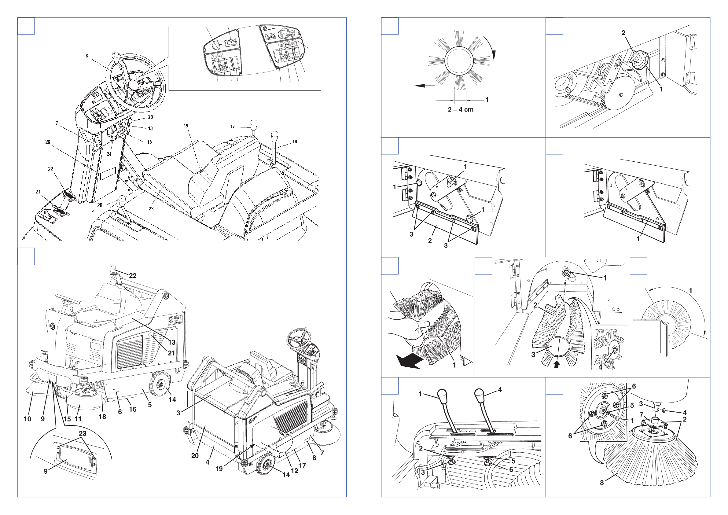
Description of the control area
(See Fig. B)
1. Hopper lifting/lowering enabling switch
2. Horn switch
3. Position for optional switch
4. Position for optional switch
5. Hour counter
6. Steering wheel
7. Steering wheel inclination adjusting knobs
8. Emergency push-button
9. Position for optional switch
10. Filter-shaker switch
11. Hopper lifting/lowering switch
12. Hopper overturning switch
13. Vacuum activation/deactivation lever
14. Engine ignition key
15. Parking brake lock control lever (in combination with
the pedal 22)
16. Forward (pushed forward) and reverse (pushed
backward) gear pedal
17. Right broom lifting/lowering lever
18. Left broom lifting/lowering lever (optional)
19. Seat longitudinal position adjusting lever
20. Main broom lifting/lowering lever
21. Front skirt lifting pedal
22. Service brake pedal (parking brake combined with
lever 15)
23. Driver's seat
24. Engine throttle lever [two position: MIN (idle speed)
and MAX (maximum speed)]
25. Working light aiming adjusting screws
26. Serial number plate
Outside view
(See Fig. C)
1. Rotating light (always on when the ignition key is on
“I” position)
2. Serial number plate/technical data/EC certification
3. Dust filter cover
4. Hopper
5. Left opening door
6. Left closure retainer
7. Right opening door
8. Right fastener
9. Working light (optional)
10. Right side broom
11. Left side broom (optional)
12. Main broom
13. Engine compartment hood
14. Rear drive wheels on fixed axis
15. Front steering wheel
16. Left side skirt
17. Right side skirt
18. Front skirt
19. Rear skirt
20. Dust filter container
21. Petrol engine exhaust pipe
Description of the under-hood compartment
(See Fig. V)
1. Hood (open)
2. Battery
3. Fuse box
4. Vacuum fan
5. Driving system hydraulic pump
6. Driving system hydraulic oil tank
7. Petrol engine
8. Fuel tank
9. Petrol filling cap
10. Engine air filter
11. Petrol engine serial number and model
12. Engine oil level dipstick
13. Engine oil filler neck
14. Petrol engine starter
15. Hydraulic pump release screw (for pushing/towing
the machine easily when the machine drive is not
available)
16. Engine oil drain plug
17. Drain plug retaining clamp
18. Engine oil drain hose
19. Hopper lifting system hydraulic oil tank
20. Hopper lifting pump drive relay
21. Hydraulic drive motors
22. Petrol engine guard
23. Guard mounting screws
24. Guard retainers
25. Left side bulkhead
26. Bulkhead mounting screws
27. Bulkhead fasteners
28. Engine oil drain hose fastener
29. Engine ignition spark plug
30. Engine silencer
31. Engine exhaust pipe end
146 2603 000(1)2005-03 A FLOORTEC R 580 P 5
Page 8

ENGLISH
USER MANUAL
TECHNICAL DATA
General Values
Cleaning width
(With one side broom)
Cleaning width
(With two side brooms)
Machine length 1,776 mm
Machine width
(With one side broom)
Machine width
(With two side brooms)
Maximum height, at the steering wheel 1,350 mm
Minimum height from ground
(Skirt not included)
Hopper maximum lifting height 1,650 mm
Minimum/maximum dumping height 270/1,370 mm
Minimum turning radius 1,690 mm
Main broom dimensions 300 mm x 800 mm
Side broom, dimensions 500 mm
Maximum forward speed 7 km/h
Maximum reverse speed 3 km/h
Gradeability 20%
Hopper capacity 130 Litres
Maximum weight liftable by the hopper 110 kg
Front axis weight in running conditions 240 kg
Rear axis weight in running conditions 390 kg
Machine total weight in running
conditions
Front wheel, steering 4.00 - 4 mm
Rear wheels, driving 4.00 - 4 mm
Sound level
(A L
)
pa
Petrol engine Data
Make Briggs & Stratton
Model Vanguard 9 HP
Adjusted power (ISO 1585) 6.3 kW
Maximum speed 3,000 rpm
Idle speed 1,450 rpm
Average consumption 0.6 Litres/hour
Oil type 15 W 40
NOTE
For other petrol engine data/values, see User's
Manual.
1,050 mm
1,310 mm
1,207 mm
1,310 mm
60 mm
630 kg
82.4 dB(A)
Dust vacuuming and filtering Values
Paper dust filter 5-10 µm 7 m
Main broom compartment vacuum 7.6 mm H2O
Electrical system Values
Battery 12 V, 65 Ah
Drive hydraulic system Values
Drive pump SAUER HIDRO-GEAR
Displacement 10.2 cc/rev
Maximum working pressure 70 Bar
Maximum peak pressure 145 Bar
Hydraulic system oil tank capacity 0.8 Litres
Hydraulic circuit total capacity 1.2 Litres
Oil type 15 W 50
2
Wiring diagram
(See Fig. AF)
Key:
ALT1: Alternator
BE1: Pivoting light
BZ1: Reverse gear buzzer
ES1: Solenoid starter
ES3: Hydraulic pump relay (forward)
ES4: Hydraulic pump relay (reverse)
F1: Ignition key fuse (25A)
F2: Charging system fuse (15A)
F3: Filter-shaker fuse relay (30A)
F4: Hopper lifting hydraulic pump fuse (30A)
F5: Hopper and filter-shaker lifting hydraulic pump
actuator fuse (10A)
F6: Horn and working light fuse (10A)
HC1: Hour counter
HN1: Horn
K1: Ignition switch
L1: Working light
M1: Starter
M2: Hopper lifting hydraulic pump
M3: Hopper lifting hydraulic pump actuator
M4: Filter-shaker motor
R1: Low engine oil relay
SWS: Safety switch
SW1: Low engine oil sensor
SW2: Reverse micro-switch
SW3: Hopper enabling switch
SW4: Hopper lifting/lowering switch
SW5: Hopper opening/closing switch
SW6: Horizontal hopper micro-switch
6 FLOORTEC R 580 P 146 2603 000(1)2005-03 A
Page 9

USER MANUAL
ENGLISH
SW7: Lifted hopper micro-switch
SW8: Open hopper micro-switch
SW9: Closed hopper micro-switch
SW10: Filter-shaker micro-switch
SW11: Horn switch
SW12: Hood microswitch
SW13: Working light switch (optional)
SPK: Petrol engine ignition spark plug
VR1: Petrol engine voltage regulator
Colour code
BK: Black
BU: Blue
BN: Brown
GN: Green
GY: Grey
OG: Orange
PK: Pink
RD: Red
VT: Violet
WH: White
YE: Yellow
Hopper lifting system hydraulic diagram
(See Fig. AG)
1. Hydraulic oil tank
2. Hydraulic oil filter
3. Hydraulic pump
4. Engine
5. Lifting cylinder safety valve
6. Hopper lifting cylinder
Drive system hydraulic diagram
(See Fig. AH)
1. Hydraulic oil tank
2. Hydraulic oil filter
3. Hydraulic pump
4. Hydraulic motors
ACCESSORIES/OPTIONS
In addition to the standard components, the machine can
be equipped with the following accessories/options,
according to the machine specific use:
– Left side broom;
– Main and side brooms with harder or softer bristles;
– Antistatic polyester or polyester BIA C dust filter;
– Pocket filter;
– Pivoting light;
– Working light;
– Non marking skirt;
– Non marking wheels;
– Protective roof.
For further information concerning the optional
accessories, contact an authorised Service Center or
Retailer.
USE
WARNING!
On some points of the machine there are
some adhesive plates indicating:
– DANGER
– WARNING
– CAUTION
–NOTE
While reading this Manual, the Operator must pay
particular attention to these symbols.
Do not cover these plates for any reason and immediately
replace them if they are damaged.
BEFORE START-UP
1. If necessary, open the hood (1, Fig. V), unscrew the
plug (9) and refuel the machine.
ELECTRICAL FUSES
Under the hood, protected by a transparent plastic cover
(3, Fig. V), there are the following fuses to protect the
related circuits:
– F1 fuse (40A) (right side of the machine): Key (main)
– F2 fuse (15A): Alternator
– F3 fuse (30A): filter-shaker
– F4 fuse (30A): Hopper/filter-shaker lifting hydraulic
pump
– F5 fuse (10A): Hopper lifting hydraulic pump actuator
– F6 fuse (10A): Horns/working lights/hour counter
– F7 fuse (40A): Spare fuse
– F8 fuse (30A): Spare fuse
CAUTION!
Do not fill the petrol tank to less than 4 cm
from the filling opening to leave room for
the gasoline to expand.
2. Check that there are no open doors/hoods and that
the machine is in normal operating conditions.
3. If the machine has not been used yet after the
transportation, check that each block and locking
system used for the transportation have been
removed.
146 2603 000(1)2005-03 A FLOORTEC R 580 P 7
Page 10

ENGLISH
USER MANUAL
STARTING AND STOPPING THE MACHINE
Starting the machine
1. Sit in the driver's seat (23, Fig. B) and, using the lever
(19) adjust the seat longitudinally, to a comfortable
position.
2. Unlock the steering wheel (6, Fig. B) by pulling the
lever (7) and adjust its tilting according to one's
comfort. After the adjustment, release the handle (7)
and lightly move the steering wheel to hook it on the
internal retainer.
3. Make sure that the parking brake is engaged with the
pedal (22, Fig. B) and the lever (15).
4. Make sure that the suction is closed by means of the
lever (13, Fig. B).
5. Make sure that the main and the side brooms are in
the lifted position by means of the levers (20, 17, 18,
Fig. B).
6. Set the engine throttle lever (24, Fig. B) on MIN (idle
speed).
7. Pull the engine choke lever (25, Fig. B).
NOTE
Do not use the choke lever if the engine is hot
and if the air temperature is sufficiently high.
8. Turn the ignition key (14, Fig. B) and start the petrol
engine. When the engine starts, release the ignition
key immediately.
CAUTION!
When starting the petrol engine, do not
keep the key (14, Fig. B) in cranking
position for too long (maximum 10
seconds) so as not to damage the starter. If
the petrol engine does not start after a few
attempts, do not insist and require
assistance from the person responsible for
the machine.
CAUTION!
When starting the engine using the ignition
key (14, Fig. B) do not activate the
forward/reverse gear pedal (16, Fig. B).
9. After the ignition, let the engine idle for a few
seconds, then release the choke lever (25, Fig. B).
10. Warm up the engine for a few minutes with the lever
in MIN position (idle speed).
11. Run the engine at working speed by positioning the
engine throttle lever (24, Fig. B) in MAX position
(maximum speed). Keep it in this position while using
the machine.
NOTE
In this condition the machine is ready to move,
all the brooms (main and side brooms) start
rotating and the dust suction system activates.
Otherwise, when the engine is at idle, it is not
possible to activate any machine function.
12. Disengage the parking brake by pressing the related
pedal (22, Fig. B) and unlocking the lever (15).
13. Start the machine and move it to the working area by
turning the steering wheel (6, Fig. B) and pressing the
pedal (16) on the front side to move forward and on
the rear side to move backward.
The drive speed can be adjusted from zero to
maximum speed by increasing the pressure exerted
on the pedal.
14. Open the suction by means of the lever (13, Fig. B)
15. Lower the main broom using the lever (20, Fig. B).
16. Activate the lever (17, Fig. B) to lower the right side
broom.
17. Activate the lever (18, Fig. B) to lower the left side
broom, if present.
NOTE
All brooms (10, 11, 12, Fig. C) can be lifted or
lowered when the machine is moving.
18. To sweep, turn the steering wheel (6, Fig. B) and
move the machine forward by pressing the pedal (16)
correctly.
Stopping the machine
1. To stop the machine, release the pedal (16, Fig. B).
To stop the machine quickly, also press the service
brake pedal (22, Fig. B).
2. Lift the main and side brooms with the related levers
(20, 17, 18, Fig. B).
3. Close the suction by means of the lever (13, Fig. B).
4. Run the engine at idle by setting the engine throttle
lever (24, Fig. B) to MIN (idle speed).
5. Stop the engine by turning the ignition key (14, Fig. B)
to “0” position and taking it off.
6. Engage the parking brake by pressing the brake
pedal (22, Fig. B) and by activating the brake lock
control lever (15).
8 FLOORTEC R 580 P 146 2603 000(1)2005-03 A
Page 11

USER MANUAL
ENGLISH
MACHINE OPERATION
1. Avoid stopping for a long time with the machine in the
same position and the brooms rotating: this could
create unwanted marks on the floor.
2. To collect light and bulky waste materials, lift the front
skirt by activating the pedal (21, Fig. B); do not keep
pushing onto the lever for a long time in order not to
reduce the suction capability of the machine.
WARNING!
When operating on wet grounds, it is
necessary to operate the lever (13, Fig. B)
and turn the suction off to prevent the dust
filter from being damaged.
3. For the machine proper operation, the dust filter must
be as clean as possible. To keep the dust filter clean
while sweeping, close the suction by means of the
related lever (13, Fig. B), then press the filter-shaker
switch (10) for a short interval; then open the suction
again.
While working, repeat the operation every 10 minutes
(depending on the dustiness of the area to be
cleaned).
NOTE
This operation can also be performed when the
machine is moving.
NOTE
When the dust filter is clogged and/or the
hopper is full, the machine cannot collect dust
and debris anymore.
4. The hopper (4, Fig. C) should be emptied after each
working period and whenever is full.
CAUTION!
In case the quantity of oil in the carter is
insufficient, the petrol engine has a warning
system to prevent damages to the engine.
Before the carter oil level goes below the
safety limit, the oil warning system
automatically stops the engine.
HOPPER EMPTYING
WARNING!
Discharge the hopper always with the
engine running at working speed.
Do not discharge the hopper with the
engine turned off, in order to avoid battery
discharge.
1. The maximum height to discharge the hopper is
1,300 mm (see Fig. U).
2. To empty the hopper, drive the machine near the
dustbin and proceed as follows:
– Lift the side and main brooms;
– Close the suction by means of the lever (13, Fig.
B);
– Press the filter-shaker switch (10, Fig. B).
WARNING!
Always carry out this operation on a level
ground to avoid machine unbalance.
3. Keep people far from the machine and especially
from the hopper (4, Fig. C).
4. Press both the enabling switch (1, Fig. B) and the
hopper lifting switch (11) to lift the hopper (1, Fig. T)
up to the desired position.
5. Press both the enabling switch (1, Fig. B) and the
hopper (12) overturning switch (2, Fig. U) and
discharge all the debris in the dustbin (1).
CAUTION!
The hopper (2, Fig. U) can be overturned
only after having lifted it at a minimum
height of 270 mm.
6. To overturn the hopper back to the horizontal
position, press the enabling switch (1, Fig. B) while
pressing the hopper overturning switch (12. Fig. B).
7. To lower the hopper, press both the enabling switch
(1, Fig. B) and the hopper lowering switch (11).
CAUTION!
The hopper can be overturned only if it is
not completely turned (horizontal position).
8. The machine is ready to start working again.
146 2603 000(1)2005-03 A FLOORTEC R 580 P 9
Page 12

ENGLISH
USER MANUAL
AFTER USING THE MACHINE
1. After working, before leaving the machine:
– Close the suction by means of the related lever
(13, Fig. B), then press the filter-shaker switch
(10, Fig. B) for a short interval; open the suction
again.
– Empty the hopper (4, Fig. C) (see previous
paragraph);
– Lift the main broom with the lever (20, Fig. B).
– Lift the side brooms with the levers (17 and 18,
Fig. B).
– Run the engine at idle by setting the engine
throttle lever (24, Fig. B) to MIN (idle speed);
– Stop the engine by turning the ignition key (14,
Fig. B) to “0” position;
– Remove the ignition key from the switch (14,
Fig. B);
– Engage the parking brake by pressing the brake
pedal (22, Fig. B), then activate the brake lock
control lever (15).
PUSHING/TOWING THE MACHINE
To push the machine, proceed as follows:
– Stop the engine by turning the ignition key (14, Fig. B)
to “0” position;
– Raise the hood (13, Fig. C).
– Remove the screw (15, Fig. V).
– Close the hood (13, Fig. C);
– Push the machine.
– After pushing the machine, install the screw (15, Fig. V).
WORKING LIGHT ADJUSTMENT
If it is necessary to adjust the working light beam aiming
(9, Fig. C), operate on the screws (23).
MACHINE LONG INACTIVITY
If you foresee that the machine will not be used for more
than 30 days, proceed as follows:
1. Check that the area where the machine is going to be
kept is dry and clean;
2. Disconnect the battery (2, Fig. V) negative terminal (–
);
3. Treat the petrol engine (7, Fig. V) according to the
indications in the related User Manual.
FIRST PERIOD OF USE
After the first period of use (first 5 hours) it is necessary to
carry out the following operations:
1. Check that the machine fastening and connecting
elements are correctly tightened; check that the
visible parts are whole and that there are no leaks;
2. Replace the petrol engine oil (see “Maintenance”
chapter).
10 FLOORTEC R 580 P 146 2603 000(1)2005-03 A
Page 13

USER MANUAL
ENGLISH
MAINTENANCE
The lifespan of the machine and its maximum operating safety are ensured by correct and regular maintenance.
The following chart provides the scheduled maintenance. The intervals shown may vary according to particular working
conditions, which are to be defined by the person in charge of the maintenance.
WARNING!
Maintenance operations must be carried out when the machine is off (on/off switch key removed).
Moreover, carefully read the instructions in the Safety chapter.
All scheduled or extraordinary maintenance operations must be performed by qualified personnel, or by an authorised
Service Center.
This manual describes only the easier and most common maintenance procedures.
NOTE
For other maintenance procedures contained in the Scheduled Maintenance Table or for extraordinary
maintenance operations see the specific Service Manual that can be consulted at any Service Center.
SCHEDULED MAINTENANCE TABLE
Maintenance operation On delivery
Engine oil level check
Battery fluid level check
Side and main broom height check
Engine air pre-filter cleaning (3)
Frame dust filter cleaning and integrity check
Hopper lifting system hydraulic oil level check
Drive system hydraulic oil level check
Skirt height and operation check
Engine oil change (2)
Filter-shaker operation check (1)
Brake adjustment (1)
Petrol filter cleaning
Drive wheel gearing chain tension check and
cleaning
Spark screen check and cleaning
Closed pocket filter cleaning and integrity check
Vacuum hose integrity check (1)
Driving belt tension visual check (1) (1)
Ignition spark plug check/cleaning
Nut and screw tightening check (1) (1)
Steering chain tension check and cleaning (1)
Safety device operation check (1)
Engine speed check (1)
Engine air filter element maintenance (3)
Spark plug replacement (2)
Engine cooling system cleaning (2)
Driving belt replacement (1) (5)
Hopper gasket integrity check (1)
Hopper lifted position control micro-switch
adjustment check
Hopper horizontal position control micro-switch
adjustment check
Engine valve clearance check/adjustment (4)
Hydraulic oil change (1)(6)
After the
first 5 hours
(1): For the related procedure, see the Service Manual
(2): or every year.
(3): or more often in dusty areas.
(4): maintenance operations to be performed by an authorized Briggs & Stratton dealer.
(5): if considered necessary by the person in charge of the maintenance.
(6): replace hydraulic oil for the first time after 500 hours, then after 2,000 hours or every year.
Every 10
hours or
before use
Every 25
hours
Every 50
hours
(1)
Every 100
hours
Every 200
hours
(1)
(1)
Every year
146 2603 000(1)2005-03 A FLOORTEC R 580 P 11
Page 14

ENGLISH
USER MANUAL
MAIN BROOM GROUND PRESSURE
CHECK
NOTE
Brooms of various hardness are available. This
procedure is applicable to all types of brooms.
1. Check the main broom for proper ground clearance,
proceeding as follows:
– Drive the machine on a level ground;
– Keep the machine stationary and rotate the
main broom for a few seconds;
– Stop and lift the main broom, then move the
machine;
– Check that the main broom print (1, Fig. D),
along its length, is from 2 to 4 cm wide.
If the print (1) is different, it is necessary to
adjust the broom pressure on the ground,
proceeding as described in step 2.
2. Disengage the retainer (6, Fig. C) and open the left
door (5).
Loose the locknut (2, Fig. E), turn the handwheel (1)
and remind that:
– To decrease the pressure of the broom on the
ground, it must be screwed.
– To increase the pressure of the broom on the
ground, it must be unscrewed.
NOTE
When the knob is completely unscrewed, you
have reached the maximum pressure of the
broom on the ground.
Screw the locknut (2, Fig. E).
3. Perform step 1 again to check the proper adjustment
of the main broom height from the ground.
4. When the broom is too worn to be adjusted, replace it
as shown in the next paragraph.
5. Engage the retainer (6, Fig. C) and close the left door
(5).
MAIN BROOM REPLACEMENT
NOTE
Brooms of various hardness are available. This
procedure is applicable to all types of brooms.
CAUTION!
It is advisable to use protective gloves
when replacing the main broom because
there can be cutting debris between the
bristles.
1. Drive the machine on a level ground and activate the
parking brake using the pedal and the lever (22 and
15, Fig. B).
2. Turn the ignition key (14, Fig. B) to “0” position.
3. Disengage the retainer (8, Fig. C) and open the right
door (7).
4. Unscrew and remove the knobs (1, Fig. F).
5. Remove the broom compartment cover (1, Fig. G).
6. Remove the broom (1, Fig. H).
7. Check that the drive hub (1, Fig. I) is free from dirt or
foreign materials (cords, clothes, etc.) accidentally
rolled up.
8. The new broom must be installed with the bristles
rows positioned as shown in the figure (2, Fig. I).
9. Install the new broom (3, Fig. I) on the machine and
ensure that its mesh (4) correctly fits on the related
drive hub (1).
10. Reinstall the broom compartment cover (1, Fig. G)
and screw the knobs (1, Fig. F).
11. Engage the retainer (8, Fig. C) and close the right
door (7).
12. Carry out the main broom pressure on the ground
check, as described in the previous paragraph.
12 FLOORTEC R 580 P 146 2603 000(1)2005-03 A
Page 15

USER MANUAL
ENGLISH
SIDE BROOM HEIGHT ADJUSTMENT
NOTE
Brooms of various hardness are available. This
procedure is applicable to all types of brooms.
1. Check the side broom height from the ground,
proceeding as follows:
– Drive the machine on a level ground;
– Keep the machine stationary, lower the side
broom and rotate it for few seconds;
– Stop and lift the side broom, then move the
machine;
– Check that the side broom print is, in extension
and orientation, as shown in the figure (1, Fig. J)
(the figure shows the right broom, the left broom
print is symmetrical).
In case the print is not within specifications, it is
necessary to adjust the broom height, proceeding as
described in the following steps.
2. Engage the parking brake using the pedal and the
lever (22 and 15, Fig. B).
3. Turn the ignition key (14, Fig. B) to “0” position.
4. Open the hood (13, Fig. C).
5. For the right side broom, use the lever (1, Fig. K):
Loosen the ring nut (2, Fig. J) and adjust the adjuster
(3) until the correct print (1) is achieved. Then fit it on
the lever by means of the ring nut (2, Fig. K).
For the left side broom, use the lever (4, Fig. K):
Loosen the ring nut (5, Fig. J) and use the adjuster
(6) to achieve the correct print (1). Then fit it on the
lever by means of the ring nut (5, Fig. K).
6. Perform step 1 again to check the proper adjustment
of the side broom height from the ground.
7. When the broom is too worn to be adjusted, replace it
as shown in the next paragraph.
SIDE BROOM REPLACEMENT
NOTE
Brooms of various hardness are available. This
procedure is applicable to all types of brooms.
CAUTION!
It is advisable to use protective gloves
when replacing the side broom because
there can be cutting debris between the
bristles.
1. Drive the machine on a level ground and activate the
parking brake using the pedal and the lever (22 and
15, Fig. B).
2. Turn the ignition key (14, Fig. B) to “0” position.
3. Activate the lever (17 or 18, Fig. B) to lift the related
side broom.
4. Unscrew the screw (1, Fig. L) inside the side broom,
then remove the broom and the hub (2) by
disengaging it from the shaft (3). Recover the key (4)
and the washer (5).
5. At the bench, remove the four screws (6, Fig. L) and
separate the broom (8) from the hub (7).
6. Install the new broom (8) onto the hub (7), and tighten
the screws (6).
7. Reinstall the broom with the hub (2, Fig. L) on the
machine after seating the key (4). Position the washer
(5) and tighten the screw (1).
8. Carry out the side broom height adjustment as
described in the previous paragraph.
146 2603 000(1)2005-03 A FLOORTEC R 580 P 13
Page 16

ENGLISH
USER MANUAL
FRAME DUST FILTER CLEANING AND
INTEGRITY CHECK
NOTE
Besides the standard paper filter, polyester
filters are also available. The following
procedure is applicable to each type of filter.
1. Drive the machine on a level ground and activate the
parking brake using the pedal and the lever (22 and
15, Fig. B).
2. Turn the ignition key (14, Fig. B) to “0” position.
3. Open the hood (13, Fig. C).
4. Remove the dust filter cover (2, Fig. M) by
disengaging it from the retainers (1).
5. Disconnect the electric connector (1, Fig. N) from the
filter-shaker.
6. Remove the filter-shaker support frame handwheels
(2, Fig. N).
7. Remove the filter-shaker support frame (3, Fig. N).
8. Pull out the dust filter (4, Fig. N) upwards.
9. In an appropriate outdoor area, clean the filter
shaking it on a level and clean surface, tapping the
side (1, Fig. O), opposite the wire gauze (2).
Complete the cleaning by means of compressed air
(3) at max. 6 bars, blowing only from the side
protected by the wire gauze (2), at a minimum
distance of 30 cm (see figure O).
According to the filter type, observe the following
cautions:
– Paper filter (standard): do not use water or
detergents to clean it; the filter can be damaged;
– Polyester filter (optional): To clean it, see the
above-mentioned instructions. If necessary, for
a better cleaning, it is allowed to wash the filter
with water and non-lathering detergents. This
provides better quality cleaning but reduces the
life of the filter, which will have to be replaced
more frequently. The use of unsuitable
detergents can damage the filter. Check the
filter body for tears.
10. If necessary clean the filter compartment rubber seal
(1, Fig. P) along its perimeter and check its integrity.
If necessary, replace it.
11. Install in the reverse order of removal (steps from 8 to
1).
NOTE
When reinstalling the filter, the wire gauze (2,
Fig. O) must be facing upward.
CLOSED POCKET DUST FILTER
CLEANING AND INTEGRITY CHECK
NOTE
The polyester closed pocket filters are normally
kept clean by activating the electric
filter-shaker supplied with the machine.
If necessary, they can be cleaned using the
procedure indicated below.
When the filtration surfaces are no longer
suitable, the filter must be replaced.
1. Drive the machine on a level ground and activate the
parking brake using the pedal and the lever (22 and
15, Fig. B).
2. Turn the ignition key (14, Fig. B) to “0” position.
3. Open the hood (13, Fig. C).
4. Remove the dust filter cover (2, Fig. M) by
disengaging it from the retainers (1).
5. Unscrew the knobs (1, Fig. AA) and remove the
brackets (2).
6. Pull out the dust filter (1, Fig. AB) upward, and
remove it after disconnecting the electrical connector
(2) from the filter-shaker.
7. Disassemble the polyester filtering surface, as
indicated by the following steps; these procedures
must be carried out in a suitable outdoor area and the
Operator must be suitably equipped (gloves, mask,
glasses).
8. Remove the filter-shaker motor (1, Fig. AC) by
unscrewing the two fixing screws.
9. Open the filter-shaker motor support unit (2, Fig. AC)
completely and release the filtering pocket tension
rods (3).
14 FLOORTEC R 580 P 146 2603 000(1)2005-03 A
Page 17

USER MANUAL
ENGLISH
10. Remove all the filtering pocket tension rods (4, Fig.
AC).
11. Open the upper retaining cord (5, Fig. AC) of the
closed pocket filter to remove it from the upper frame
(6).
12. Remove the internal pocket separator (7, Fig. AC).
13. Clean the polyester fiber surface (8, Fig. AC) from the
dirty side, using an external vacuum cleaner,
spreading it out completely or cleaning pocket by
pocket. At the same time, clean both the surfaces of
the pocket separator (7, Fig. AC) removing anything
deposited on them. Check the filtering surface for
tears. In case of tears, replace it. It is also possible to
use compressed air (max. 6 Bar), blowing the air from
the clean side towards the dirty side.
WARNING!
Do not wash the filter with water. The
polyester fibber can shrink and become
unusable.
14. Reassemble all the filter components in the reverse
order of disassembly.
15. If necessary, clean the filter compartment rubber seal
(3, Fig. AB) along its perimeter and check its integrity.
If necessary, replace it.
16. Reassemble all the components in the reverse order
of disassembly.
Front and rear skirt
7. Remove the main broom, as described in the related
paragraph.
8. Check the front (1, Fig. W) and rear (2) skirts for
integrity.
Replace the skirts when they have cuts (1, Fig. Q)
larger than 20 mm or cracks/tears (2) larger than 10
mm (for skirt replacement, see the Service Manual).
9. Check that the front (1, Fig. W) and rear (2) skirts rub
lightly on the floor but are not completely lifted from
the ground (Fig. S).
After loosening the screws (3, Fig. W), adjust the skirt
position if necessary.
Then tighten the screws (3).
10. Press the front (21, Fig. B) skirt lifting pedal
completely, and check that the front skirt lifts 5 cm
approximately. Release the pedal and check that the
skirt returns to the initial position and not in an
intermediate position. If necessary, adjust the skirt
lifting cable (1, Fig. X), by means of the adjuster (2)
on the left front side of the skirt (for the front skirt
control cable replacement, see the Service Manual).
11. Reassemble the removed components in the reverse
order of disassembly.
HOPPER LIFTING SYSTEM HYDRAULIC
OIL LEVEL CHECK
SKIRT HEIGHT AND OPERATION CHECK
Side skirts
1. Drive the machine on a level ground that is suitable
for checking the skirt height.
2. Engage the parking brake using the pedal and the
lever (22 and 15, Fig. B).
3. Turn the ignition key (14, Fig. B) to “0” position.
4. Disengage the retainers (8 and 6, Fig. C) and open
the right and left doors (7 and 5).
5. Check the side skirt (2, Fig. F) integrity.
Replace the skirts when they have cuts (1, Fig. Q)
larger than 20 mm or cracks/tears (2) larger than 10
mm (for skirt replacement, see the Service Manual).
6. Check that side skirt (2, Fig. F) height from ground is
within 0 – 3 mm (Fig. R).
After loosening the screws (3, Fig. F), if necessary,
adjust the skirt position.
Then tighten the screws (3).
CAUTION!
These operations must be performed with
the hopper (4, Fig. C) in its original position
(as shown in the figure).
1. Engage the parking brake using the pedal and the
lever (22 and 15, Fig. B).
2. Turn the ignition key (14, Fig. B) to “0” position.
3. Open the hood (1, Fig. V).
4. Check that the hydraulic oil level in the tank (19, Fig.
V) is between the MIN (minimum level) and MAX
(maximum level) marks shown in figure Y.
5. If necessary, add hydraulic oil - viscosity grade 32 cSt
- through the plug (1, Fig. Y).
6. Close the hood (1, Fig. V).
146 2603 000(1)2005-03 A FLOORTEC R 580 P 15
Page 18

ENGLISH
USER MANUAL
DRIVE SYSTEM HYDRAULIC OIL LEVEL
CHECK
1. Engage the parking brake using the pedal and the
lever (22 and 15, Fig. B).
2. Turn the ignition key (14, Fig. B) to “0” position.
3. Open the hood (1, Fig. V).
4. Check that the hydraulic oil level in the tank (6, Fig. V)
is between the MIN (minimum level) and MAX
(maximum level) marks shown in figure Z.
5. If necessary, top up the oil through the plug (1, Fig. Z)
using engine oil 15 W 50.
6. Close the hood (1, Fig. V).
ENGINE OIL LEVEL CHECK
1. Drive the machine on a level ground.
2. Engage the parking brake using the pedal and the
lever (22 and 15, Fig. B).
3. Turn the ignition key (14, Fig. B) to “0” position.
4. Open the hood (1, Fig. V).
5. Unscrew the screws (23, Fig. V) and remove the
engine guard (22) by disengaging the retainers (24).
6. Remove the engine oil level dipstick (12, Fig. V) and
clean it with a clean cloth. Insert the dipstick (12, Fig.
AD), take it out after a few seconds and check that the
oil level is between the MIN (minimum level) and MAX
(maximum level) marks (1).
If the oil level is lower than the MIN (minimum level)
mark, remove the filler plug (13, Fig. V) and top up.
CAUTION!
Top up using the same type of oil as that in
the engine.
7. Reinstall the filler plug (13, Fig. V) and check the oil
level as described in the previous steps. Insert the
dipstick (12, Fig. V) again.
8. Carry out steps from 1 to 5 in the reverse order.
ENGINE OIL REPLACEMENT
CAUTION!
It is advisable to replace the oil when the
engine is still hot, to make the oil downflow
easier.
1. Drive the machine on a level ground.
2. Engage the parking brake using the pedal and the
lever (22 and 15, Fig. B).
3. Turn the ignition key (14, Fig. B) to “0” position.
4. Unscrew the screws (26, Fig. V) and disengage the
retainers (27) to remove the left side bulkhead (25).
5. Open the hood (1, Fig. V).
6. Unscrew the screws (23, Fig. V) and remove the
engine guard (22) by disengaging the retainers (24).
7. Remove the engine oil level dipstick (12, Fig. V) and
clean it with a clean cloth.
8. Disconnect the engine oil drain pipe (18, Fig. V) from
the retainer (28) and lower it to discharge the engine
oil into a container.
9. Loosen the clamp (17, Fig. V); remove the engine oil
drain plug (16) and let the engine oil downflow in the
container.
CAUTION!
The removed engine oil must be disposed
of properly according to the Law in force.
10. Reassemble the plug (16, Fig. V) and fix it by means
of the clamp (17).
11. Lift the pipe (18, Fig. V) and fix it by means of the
retainer (28).
12. Remove the filler plug (13, Fig. V).
13. Pour the new oil through the filler opening (13, Fig. V).
NOTE
As for engine type and quantity, see the
Technical Data chapter and the Petrol Engine
Manual.
14. Reinstall the filler plug (13, Fig. V).
15. Insert the engine oil dipstick (12, Fig. V), take it out
after a few seconds and check that the oil level is
between the MIN (minimum level) and MAX
(maximum level) marks (1, Fig. AD). If necessary, top
up.
Then insert the dipstick (12, Fig. V) again.
16. Carry out steps from 1 to 6 in the reverse order.
16 FLOORTEC R 580 P 146 2603 000(1)2005-03 A
Page 19

USER MANUAL
ENGLISH
PETROL FILTER CLEANING
1. Drive the machine on a level ground.
2. Engage the parking brake using the pedal and the
lever (22 and 15, Fig. B).
3. Turn the ignition key (15, Fig. B) to “0” position.
4. Unscrew the screws (26, Fig. V) and disengage the
retainers (27) to remove the left side bulkhead (25).
5. Unscrew the screws (7, Fig. AE) and remove the
engine air conveyor (8).
6. Clean the petrol filter (10, Fig. AS) as indicated in the
Petrol Engine Manual.
7. Carry out steps from 1 to 5 in the reverse order.
ENGINE AIR PRE-FILTER CLEANING AND
ENGINE AIR FILTER CARTRIDGE
MAINTENANCE
1. Drive the machine on a level ground.
2. Engage the parking brake using the pedal and the
lever (22 and 15, Fig. B).
3. Turn the ignition key (14, Fig. B) to “0” position.
4. Unscrew the screws (26, Fig. V) and disengage the
retainers (27) to remove the left side bulkhead (25).
5. Remove the pin (1, Fig. AE) from its seat (9) and
insert it in the hole (2) of the lever (5).
6. Lower the main broom by means of the lever (20, Fig.
B) to disengage the rod (3, Fig. AE).
7. Disengage and remove the pin (4, Fig. AE), then
disconnect the tie rod (3) from the lever (5).
8. Clean the engine air pre-filter and/or perform the
petrol engine filter cartridge (6, Fig. AE), maintenance
as indicated in the Petrol Engine Manual.
9. Carry out steps from 1 to 7 in the reverse order.
ENGINE SPARK PLUG
CLEANING/REPLACEMENT
1. Drive the machine on a level ground.
2. Engage the parking brake using the pedal and the
lever (22 and 15, Fig. B).
3. Turn the ignition key (14, Fig. B) to “0” position.
4. Open the hood (1, Fig. V).
5. Unscrew the screws (23, Fig. V) and remove the
engine guard (22) by disengaging the retainers (24).
6. Clean/replace the spark plug (29, Fig. V) as indicated
in the Petrol Engine Manual.
7. Carry out steps from 1 to 5 in the reverse order.
ENGINE COOLING SYSTEM CLEANING
1. Drive the machine on a level ground.
2. Engage the parking brake using the pedal and the
lever (22 and 15, Fig. B).
3. Turn the ignition key (14, Fig. B) to “0” position.
4. Unscrew the screws (26, Fig. V) and disengage the
retainers (27) to remove the left side bulkhead (25).
5. Open the hood (1, Fig. V).
6. Unscrew the screws (23, Fig. V) and remove the
engine guard (22) by disengaging the retainers (24).
7. Unscrew the screws (7, Fig. AE) and remove the
conveyor (8).
8. Clean the engine cooling system (11, Fig. AE) as
indicated in the Petrol Engine Manual.
9. Carry out steps from 1 to 7 in the reverse order.
SPARK SCREEN CLEANING
1. Drive the machine on a level ground.
2. Engage the parking brake using the pedal and the
lever (22 and 15, Fig. B).
3. Turn the ignition key (14, Fig. B) to “0” position.
4. Unscrew the screws (26, Fig. V) and disengage the
retainers (27) to remove the left side bulkhead (25).
5. Unscrew the fixing screws and remove the engine
exhaust system end (31, Fig. V).
6. Clean the spark screen as indicated in the Petrol
Engine Manual.
7. Carry out steps from 1 to 5 in the reverse order.
146 2603 000(1)2005-03 A FLOORTEC R 580 P 17
Page 20

ENGLISH
USER MANUAL
SAFETY FUNCTIONS
The machine is equipped with the following safety
functions.
HOOD SAFETY SWITCH
Turns off the engine when the hood (13, Fig. C) is open.
EMERGENCY PUSH-BUTTON
It is located in a position (8, Fig. B) that is easily accessible
for the Operator.
It must be pressed in case of emergency, to stop all the
machine functions.
HOPPER LIFTING/LOWERING AND
OVERTURNING ENABLING SWITCH
It is in the position (1, Fig. B) and must be pressed and
held to activate the hopper lifting/lowering and overturning
switches.
HOPPER LIFTING CYLINDER SAFETY
VALVE
It is located on the hopper lifting cylinder.
It stops the hopper in the position it has reached (without
possibility for it to lower accidentally) if the hydraulic
system piping, feeding the lifting cylinder should break.
PETROL ENGINE STOP DEVICE IN CASE
OF INSUFFICIENT ENGINE OIL LEVEL
The petrol engine is equipped with an internal devices that
checks the correct engine oil level and stops the engine if
the level should be insufficient.
TROUBLESHOOTING
TROUBLE REMEDY
The petrol engine does not
start if activated with the
ignition key.
The petrol engine stops
during operation
The machine collects little
debris/dust.
When the forward/reverse
gear pedal is pushed the
machine does not move, or
it moves slowly
The hopper does not lift Check that the hydraulic oil level in the lift ing unit
The hopper does not
overturn
The hopper does not lower Before lowering the hopper by means of the
The brooms do not rotate
correctly.
With the engine
compartment (13, Fig. C)
hood lifted, the petrol
engine keeps running.
Check that the hood (13, Fig. C) is closed.
Check that the engine oil level is sufficient (*).
Check that the petrol tank (8, Fig. V) contains the
appropriate kind of fuel.
Check that the petrol reaches the carb urettor and
the petrol filter is clean (*).
Check that the spark plug produces a spark (*).
Check that the engine oil level is sufficient (*).
Check that the petrol tank (8, Fig. V) contains the
appropriate kind of fuel.
Check that the petrol filter is clean (*).
Check that the dust filter (3, Fig. C) is not
clogged.
Check that the hopper (4, Fig. C) is not full.
Check that the skirts (16, 17, 18, 19, Fig. C) are
not broken or incorrectly adjusted.
Check that the brooms (10, 11, 12, Fig. C) are at
the correct height.
Check that the parking brake (22 with 15, Fig. B)
has been released.
Check that the engine throttle lever (24, Fig. B) is
on MAX (maximum speed).
Check that the hydraulic oil level in the tank (6,
Fig. V) is correct.
Check that the centrifugal pulley (petrol
engine-drive pump coupling joint) operates
properly.
Check that the forward speed pedal is correctly
adjusted and it activates the drive pump
correctly.
tank (19, Fig. V) is correct.
Check that the control electrical connectors are
correctly connected.
Check that the hopper is not excessively loaded
(hydraulic lifting capacity exceeded). In this case,
unload the hopper.
Check that the hopper is lifted from the gro und at
an height greater than 270 mm.
Check that the control electrical connectors are
correctly connected.
related switch (11, Fig. B), check that the hopper
has returned to the horizontal position by means
of the related switch (12, Fig. B).
Wait a few minutes to allow the lifting cylinder
hydraulic oil to flow out through its interior
parachute valve; if the valve is stuck, it could be
necessary to press the lowering switch (12, Fig.
B) again.
Check that the broom control belt tension is
correct.
Turn the throttle lever (24 fig. B) to MAX
(maximum speed), and check that the centrifugal
pulley engages.
Malfunction of the hood safety micro-switch.
Please contact the Nilfisk-Alto Service Center.
(*): For the related procedure, see the Petrol Engine User
Manual.
For further information, refer to the Service Manual,
available at any Nilfisk-Alto Service Center.
18 FLOORTEC R 580 P 146 2603 000(1)2005-03 A
Page 21

SCRAPPING
Have the machine scrapped by a qualified scrapper.
Before scrapping the machine, always remove the following materials:
– Polyester dust filter
– Main and side brooms
– Engine oil
– Hydraulic oil
– Plastic components and hoses
CAUTION!
The removed components must be disposed of properly according to the Law in force.
USER MANUAL
ENGLISH
146 2603 000(1)2005-03 A FLOORTEC R 580 P 19
Page 22

ENGLISH
$
*
O
(&
((&
$SSOLHGK
$SSOLHG
O
\
USER MANUAL
EC CERTIFICATE OF CONFORMITY
GHFODUDWLRQRIFRQIRUPLW
OWR'HXWVFKODQG*PE+
XLGR2EHUGRUIHU6WUDH
%HOOHQEHUJ
URGXFW
RGH
'HVFULSWLRQ
KHGHVLJQRIWKHDSSOLDQFHFRUUHVSRQGV
RWKHIROORZLQJSHUWLQHQWUHJXODWLRQV
DUPRQL]HGVWDQGDUGV
QDWLRQDOVWDQGDUGVDQGWHFKQLFD
VSHFLILFDWLRQV
ZHHSHU
)/2257(&5
ULJJV6WUDWWRQ
(&0DFKLQH'LUHFWLYH
(&(0&'LUHFWLYH
(&'LUHFWLYHPRWRUYHKLFOHHPLVVLRQ(&
(1(1(1(1
(1
(1(1
,1(1
,635
WUROHQJLQH
LSO,QJ:ROIJDQJ1LHXZNDPS
HVWVDQGDSSURYDOV
20 FLOORTEC R 580 P 146 2603 000(1)2005-03 A
HOOHQEHUJ
Page 23

S310190
AF
SW6
M4
HN1
ES1
BATTERY
L1
K1
M1
ALT.
1
SW
3
BE1
SPK
BZ1
30
30/1
15
50
15/5
4
HC1
M2
ES3
ES4
SW
4
R1
SW1
VR1
F1
F2
F3
F4
F5
F6
SW13
SW11
SW10
RD
RD
RD
WH
GY
OG
YE
BU
BN
YE
VT
VT
VTB
K
BUBK
87a
87
30
86
85
86
85
87
87a
30
BN
BU
GY-BK
GY
WH
BKWH
SW8
SW7
apre
chiude
0V
SW5
VT
BU
PK
SW9
PK
BU
M3
RD
VT
BU
GN
BK
BUBK
VT
BK
BK
BK
BK
BK
RD
BU
SWS
SW12
BU
BKBU
VTW
H
SW2
BK
VT
BU
-
+
Page 24

S310191
AG
AH
S310132
Page 25

S310121 S310122
S310124
S310037
S310125
S310192
S310039
S310126
M N
O P
RQ
T U
V
S310128
S
W X
S310038
S310183
S310127
Page 26

Y
S310189
AUSTRALIA
Australia
AUSTRIA
ALTO Österreich GmbH
Austria
www.nilfi sk-alto.at
ALTO Canada
ALTO Ceskà republika s.r.o.
www.nilfi sk-alto.dk
www.nilfi sk-alto.com
ALTO France SA
Aéroparc 1
www.nilfi sk-alto.com
www.nilfi sk-alto.de
www.nilfi sk-alto.co.uk
ALTO Hungary Kft
ALTO DEN-SIN Malaysia Sdn Bhd
ALTO Nederland B.V.
ALTO Norge AS
www.nilfi sk-alto.no
ALTO DEN-SIN
www.nilfi sk-alto.com
ALTO Sverige AB
Aminogatan 18, Box 40 29
www.nilfi sk-alto.se
ALTO U.S. Inc.
ALTO U.S.Inc
Arkansas 72764
ALTO U.S.Inc
ALTO Cleaning Systems, Inc.
www.nilfi sk-alto.com
Z
S310184 S310185
AA
AB
AC
AD
S310186 S310187
S310145
S310188
AE
2
1
5
6
4
3
8
7
 Loading...