

Page 1
INSTALLATION & OPERATION GUIDE
MVC HUB4
MVC HUB4
Niles Audio Corporation
www.nilesaudio.com
12331 S.W. 130 Street
Miami, Florida 33186
Tel: (305) 238-4373
Fax: (305) 238-0185
©2003 Niles Audio Corporation. All rights reserved. Niles, the Niles logo, and Blending Technology and Architecture are registered trademarks of Niles Audio Corporation. Decora is a registered trademark of Leviton Manufacturing. All other trademarks
are the property of their respective owners. Some of Niles products (or components thereof) are manufactured under one or more
U.S. Patents, foreign equivalents and/or pending patents (see product for details). Because we constantly strive to improve our
products, Niles reserves the right to change product specifications, descriptions, and prices without notice. The technical and
other specifications of information contained herein is not intended to set forth all technical and other specifications of Niles
products. Additional information can be obtained at www.nilesaudio.com or by calling Niles at 1-800-289-4434. Printed in
China 7/03 DS00314ACN
Muting Volume Control Distribution Hub
B LENDING H IGH F IDELITY AND A RCHITECTURE
®
Page 2
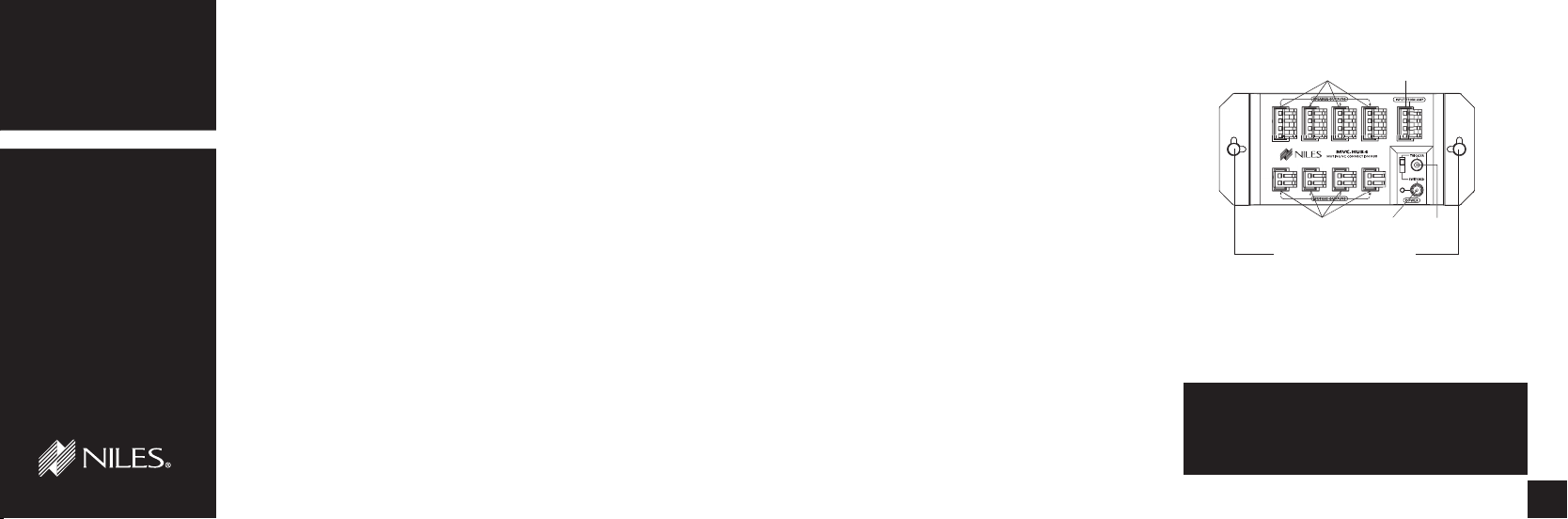
Snap-in "Christmas tree" plugs
Speaker outputs
to volume controls
12V
outputs t
o
volume controls
Amplifier
input
Power
input
Tri
gge
r
input
M UTING V OLUME C ONTROL D ISTRIBUTION H UB
M UTING V OLUME C ONTROL D ISTRIBUTION H UB
MVC HUB4
TABLE OF CONTENTS
Introduction 1
Features and
Benefits 2
Installation
Considerations 2
Installation 4
Specifications 6
Contents 6
INTRODUCTION
The MVC HUB4 is a speaker/power distribution hub for use with Niles muting volume
controls. It connects the speaker-level output of an amplifier or receiver to the muting volume
controls and provides 12V power to the muting volume controls.
When you install a Niles MVC HUB4 Speaker/Power Hub in conjunction with Niles muting
volume controls (MVC 100, WMVC 100 and/or WMVC 100E), the automatic muting feature is
programmable. This allows certain locations (such as the guest bedroom and porch) to remain
muted when system activation turns on other locations (such as the kitchen and family room).
A system with volume controls for multiple speaker pairs connected directly to an amplifier or
receiver requires a large number of connecting wires. This creates an unsightly and often inconvenient installation, and increases the potential for connection errors.
The Niles MVC HUB4 eliminates such problems. Simply run a single set of wires from the
amplifier or receiver to the speaker connectors and the 12V power plug on the distribution hub,
and then connect each of the muting volume controls to the distribution hub.
The only product of its kind on the market, the MVC HUB4 allows you to distribute both the
speaker-level output and the switched power output from your amplifier or receiver to the muting volume controls for up to four pairs of stereo speakers.
The MVC HUB4 mounts conveniently in a structured-wiring cabinet or on a wall.
FEATURES AND BENEFITS
The MVC HUB4 offers a number of improvements over other
speaker/power distribution hubs:
● Rustproof, weather-resistant housing of high-impact, injec-
tion-molded plastic.
● Removable connector blocks for convenient wire connections.
● LED voltage indicator.
● Built-in protection circuit prevents equipment damage from
incorrect wiring.
● Small size and compact footprint, designed specifically to fit
into a standard structured-wiring cabinet.
● Snap-in “Christmas tree” plugs (supplied) for quick and easy
installation in a structured-wiring cabinet.
● Also suitable for wall-mounting.
● Ideal for home and commercial sound installations.
● UL-rated to comply with all local building codes.
● 10 years parts and labor warranty.
Figure 1
INSTALLATION CONSIDERATIONS
Calculating the Impedance Magnification Setting
To ensure optimal operation of your amplifier or receiver, your
speakers must show it a load that it can handle safely and
effectively. This requires the use of impedance-magnifying (IM)
volume controls.
TECH TIP
Some speakers have selectable impedance.
Before you proceed, please confirm that any
selectable-impedance speakers in your system
are properly set for the system you are installing.
2
Page 3

M UTING V OLUME C ONTROL D ISTRIBUTION H UB
2x
8x
AMPLIFIER’S MINIMUM SPEAKER LOAD IS 4 OHMS
0
1
2
3
4
5
6
7
8
2x
4x
8x
012345678910111213141516
8 OHM Speaker Pairs
4 OHM
Speaker
Pairs
1x
8x
4x
8x
4x
4x
AMPLIFIER
S
MINIMUMSPEAKER
L
O
AD I
S8OHMS
4 OH
M
Speake
r
Pair
s
023
234
5
678
12 AWG
14 AWG
M UTING V OLUME C ONTROL D ISTRIBUTION H UB
Figure 2
Figure 3
CAUTION! Every speaker pair in the system must be connected to an impedance-magnifying volume control and set to
the same magnification.
When you install the MVC HUB4 and connect the volume
controls to it, doublecheck the switches on the volume controls
to verify that they are set correctly for the impedance load of
your speakers.
Use the following instructions and the accompanying charts to
select the correct switch setting on the volume controls for the
number and type of speakers in your system.
1. Count the number of pairs of 4-ohm speakers and the number of pairs of 8-ohm speakers you are connecting. Count
pairs of 6-ohm speakers as 4-ohm pairs.
2. Determine whether the amplifier should see a 4-ohm load or
an 8-ohm load. You should find this information in the
owner’s manual of the amplifier.
3. Read the correct switch position from the charts on the next
page. See Figure 2 if your amplifier can drive a 4-ohm
load. See Figure 3 if your amplifier must have an 8-ohm
speaker load.
4. Set the switches on all of the controls to the same position
(1x, 2x, 4x, or 8x).
Type of Speaker Wire
We recommend 16-gauge str anded copper speaker wire for
most connections, and 14-gauge wire for runs longer than 80
feet. Don’t use speaker wire larger than 14 gauge, because larger wire may not fit into the connectors. Never use solid-core,
aluminum, or Romex wire with an IM volume control. For
speaker-wire runs within walls, most U.S. states and municipalities require a special type of speaker wire with a specific CL fire
rating, such as CL-2 or
CL-3. Consult your Niles
dealer, building contractor, or local buildinginspection department if
you aren’t sure what kind
of wire is best for your
application.
Mounting Location
The MVC HUB4 is
designed specifically to fit
into a structured-wiring
TECH TIP
Wire size is expressed by its
AWG (American Wire Gauge)
number. The lower the AWG
number, the larger the wire.
Thus, 12 AWG wire is physically larger than 14 AWG.
cabinet, with snap-in
“Christmas tree” plugs for convenient installation.
Alternatively, you can mount it on a wall, a basement floor joist,
or some other unobtrusive location.
INSTALLATION
1. Run all necessary wiring to the MVC HUB4. Label the wires
for future reference.
2. Secure the MVC HUB4 in a suitable location. In a structuredwiring cabinet, use the convenient snap-in “Christmas tree”
plugs (supplied) to mount it in the cabinet frame. On a wall
or other flat surface, remove the snap-in plugs, insert drywall
screws (not supplied) through the resulting holes, and secure
the screws to the mounting surface. DON’T OVERTIGHTEN
THE SCREWS, WHICH COULD DAMAGE THE HOUSING.
3. Locate the connector plugs (and remove them if they are
plugged in). The four-position connector plugs are for speaker wires; the two-position connector plugs are for 12V wires.
See Figure 1
4. Strip 1/4" of insulation from the end of each wire. Tightly twist
the end of each wire until no frayed ends remain.
5. Use a small flathead screwdriver or your thumbnail to raise
the locking tabs, exposing the holes on the removable connector plug.
6. Insert each wire into the appropriate
hole on the removable connector plug,
and snap the locking tab down.
NOTE: Maintain proper phasing. Connect
the positive terminals on the MVC HUB4
to the positive terminals on the amplifier
or receiver, and on the volume controls.
Connect the negative terminals on the
MVC HUB4 to the negative terminals on
the amplifier or receiver, and on the volume controls. To help you avoid improp-
Figure 4
43
Page 4

M UTING V OLUME C ONTROL D ISTRIBUTION H UB
M UTING V OLUME C ONTROL D ISTRIBUTION H UB
er phasing, the connector plug is keyed. Insert the smooth side
of the connector plug into the smooth side of the socket. Don’t
force the scalloped side of the connector plug into the smooth
side of the socket. See Figure 4.
7. Plug the connectors into the MVC HUB4 as shown in
Figure 4. The single four-position connector plug at lower
right is the speaker-wire input from the amplifier or receiver.
The other four-position connector plugs are the speaker-wire
outputs, each leading to a specific volume control. The
two-position connector plugs are the 12V power outputs,
each leading to a specific volume control.
8. Connect the power-supply wiring. Use a Niles Triggering
Power Supply (FG00666) that converts 110V AC to 12V DC
at 500mA. Plug the AC end into the switched outlet on
the receiver; plug the DC end into the 12V female plug on
the MVC HUB4.
TECH TIP
Maintain proper polarity. If the MVC-HUB4 is not in
the same location as the amplifier or receiver, you
must splice the AC and DC ends of the Triggering
Power Supply onto the wire running from the
amplifier or receiver to the hub.
PROGRAMMING CAPABILITY
Using Niles muting volume controls (MVC 100, WMVC 100,
and/or WMVC 100E) enables you to program individual muting volume controls attached to an MVC HUB4. This allows
certain locations (such as the guest bedroom and porch) to
remain muted when system activation turns on other locations
(such as the kitchen and family room).
To set a pair of speakers attached to a Niles muting volume
control for automatic muting or unmuting, press and hold the
mute button for 10 seconds. An LED blinks to indicate that programming has occurred.
Niles muting volume controls come from the factory preprogrammed in the automatic mute mode. They will unmute
the first time you reprogram them. To restore automatic muting,
reprogram them again.
SPECIFICATIONS
Mounting
In a structured-wiring cabinet, using convenient snap-in
“Christmas tree” plugs (supplied)
On a wall or other flat surface, secured with drywall screws
(not supplied)
iring Requirements
W
14-18 gauge, two individual runs of two-conductor speaker
wire, or one run of four-conductor speaker wire.
Niles Triggering Power Supply (FG00665), converts 110V AC to
12V DC at 200mA
Unit Dimensions
6.85" wide x 3" high x 1.3" deep
CONTENTS
MVC HUB4
• MVC HUB4
• Snap-in “Christmas Tree” plugs X2
• Removable 12V control connectors X5
• Removable speaker connector X5
65
 Loading...