

Page 1

INSTALLATION & OPERATION GUIDE
A4.6Ci
A4.6Ci
MultiZone Audio Preamplifier
B LENDING T ECHNOLOGY AND A RCHITECTURE
®
Four-Source, Six-Zone Preamplifier
Page 2

Congratulations!
Thank you for purchasing the Niles A4.6Ci MultiZone Preamplifier, one of the most flexible and convenient
audio components ever offered. The A4.6Ci, like all Niles products, is built to the highest standards of quality
and reliability. With proper installation and operation, you'll enjoy years of trouble-free use.
Niles manufactures the industry's most complete line of custom installation components and accessories for
audio/video systems. For a free full-line catalog, write:
Niles, Catalog Request, P.O. Box 160818, Miami, Florida 33116-0818
Table Of Contents
INTRODUCTION . . . . . . . . . . . . . . . . . . . . . . . . . . . . . . . . . . . . . . . . . . . . . . . . . . . . . . . . . . . . . . . . . . . . . . . . . .6
FEATURES AND BENEFITS . . . . . . . . . . . . . . . . . . . . . . . . . . . . . . . . . . . . . . . . . . . . . . . . . . . . . . . . . . . . . . . . . . .7
PARTS GUIDE . . . . . . . . . . . . . . . . . . . . . . . . . . . . . . . . . . . . . . . . . . . . . . . . . . . . . . . . . . . . . . . . . . . . . . . . . . . . .9
A4.6Ci . . . . . . . . . . . . . . . . . . . . . . . . . . . . . . . . . . . . . . . . . . . . . . . . . . . . . . . . . . . . . . . . . . . . . . . . . . . . . . . .10
IntelliPad Ci Keypad Modules . . . . . . . . . . . . . . . . . . . . . . . . . . . . . . . . . . . . . . . . . . . . . . . . . . . . . . . . . . . . . . .11
R-4 Remote Control . . . . . . . . . . . . . . . . . . . . . . . . . . . . . . . . . . . . . . . . . . . . . . . . . . . . . . . . . . . . . . . . . . . . . .12
SYSTEM CONFIGURATIONS . . . . . . . . . . . . . . . . . . . . . . . . . . . . . . . . . . . . . . . . . . . . . . . . . . . . . . . . . . . . . . . . . .13
Configuration 1-Six Zones . . . . . . . . . . . . . . . . . . . . . . . . . . . . . . . . . . . . . . . . . . . . . . . . . . . . . . . . . . . . . . . . . .13
Configuration 2-Adding Zones Using Multiple A4.6Ci’s . . . . . . . . . . . . . . . . . . . . . . . . . . . . . . . . . . . . . . . . . . . .15
Configuration 3-Integrating an IR-Controlled Home Theater . . . . . . . . . . . . . . . . . . . . . . . . . . . . . . . . . . . . . . . . .16
Configuration 4-Integrating a Home Theater using an Intellicontrol . . . . . . . . . . . . . . . . . . . . . . . . . . . . . . . . . . .17
Configuration 5-Multiple Master Keypad Modules in a Zone . . . . . . . . . . . . . . . . . . . . . . . . . . . . . . . . . . . . . . . .18
Configuration 6-Multiple Listening Areas in a Zone . . . . . . . . . . . . . . . . . . . . . . . . . . . . . . . . . . . . . . . . . . . . . . .19
Configuration 7-More than One Room in a Zone . . . . . . . . . . . . . . . . . . . . . . . . . . . . . . . . . . . . . . . . . . . . . . . .20
Configuration 8-System Paging with an External Telephone System . . . . . . . . . . . . . . . . . . . . . . . . . . . . . . . . . . .21
Configuration 9-IR Repeating for Control of Local Components . . . . . . . . . . . . . . . . . . . . . . . . . . . . . . . . . . . . . .22
COMPONENT COMPATIBILITY . . . . . . . . . . . . . . . . . . . . . . . . . . . . . . . . . . . . . . . . . . . . . . . . . . . . . . . . . . . . . . .23
Infrared Command Compatibility . . . . . . . . . . . . . . . . . . . . . . . . . . . . . . . . . . . . . . . . . . . . . . . . . . . . . . . . . . . .23
SOURCE-POWER SYNCHRONIZATION . . . . . . . . . . . . . . . . . . . . . . . . . . . . . . . . . . . . . . . . . . . . . . . . . . . . . . . . .24
Choosing A Synchronization Method . . . . . . . . . . . . . . . . . . . . . . . . . . . . . . . . . . . . . . . . . . . . . . . . . . . . . . . . .25
Source and Home Theater Sync Status . . . . . . . . . . . . . . . . . . . . . . . . . . . . . . . . . . . . . . . . . . . . . . . . . . . . . . . .27
2
TABLE OF CONTENTS
Page 3

OPERATIONAL OVERVIEW . . . . . . . . . . . . . . . . . . . . . . . . . . . . . . . . . . . . . . . . . . . . . . . . . . . . . . . . . . . . . . . . . .28
Master Keys/Source Buttons . . . . . . . . . . . . . . . . . . . . . . . . . . . . . . . . . . . . . . . . . . . . . . . . . . . . . . . . . . . . . . . . .28
Master Key/Source Button Events . . . . . . . . . . . . . . . . . . . . . . . . . . . . . . . . . . . . . . . . . . . . . . . . . . . . . . . . . . . . .29
Master Key/Source Button Operation . . . . . . . . . . . . . . . . . . . . . . . . . . . . . . . . . . . . . . . . . . . . . . . . . . . . . . . . . .30
OFF Key/OFF Button . . . . . . . . . . . . . . . . . . . . . . . . . . . . . . . . . . . . . . . . . . . . . . . . . . . . . . . . . . . . . . . . . . . . . .30
OFF Key Events . . . . . . . . . . . . . . . . . . . . . . . . . . . . . . . . . . . . . . . . . . . . . . . . . . . . . . . . . . . . . . . . . . . . . . . . . .31
OFF Key/button Operation . . . . . . . . . . . . . . . . . . . . . . . . . . . . . . . . . . . . . . . . . . . . . . . . . . . . . . . . . . . . . . . . .31
Volume Keys/Volume Buttons . . . . . . . . . . . . . . . . . . . . . . . . . . . . . . . . . . . . . . . . . . . . . . . . . . . . . . . . . . . . . . .32
Volume Keys/Volume Buttons Operation . . . . . . . . . . . . . . . . . . . . . . . . . . . . . . . . . . . . . . . . . . . . . . . . . . . . . . .32
Mute Key/Mute Button . . . . . . . . . . . . . . . . . . . . . . . . . . . . . . . . . . . . . . . . . . . . . . . . . . . . . . . . . . . . . . . . . . . .33
Mute Key/Mute Button Operation . . . . . . . . . . . . . . . . . . . . . . . . . . . . . . . . . . . . . . . . . . . . . . . . . . . . . . . . . . . .33
Function Keys/Buttons . . . . . . . . . . . . . . . . . . . . . . . . . . . . . . . . . . . . . . . . . . . . . . . . . . . . . . . . . . . . . . . . . . . . .34
Function Key/Button Operation . . . . . . . . . . . . . . . . . . . . . . . . . . . . . . . . . . . . . . . . . . . . . . . . . . . . . . . . . . . . . .34
identical Source Components . . . . . . . . . . . . . . . . . . . . . . . . . . . . . . . . . . . . . . . . . . . . . . . . . . . . . . . . . . . . . . .35
Shared Source Components . . . . . . . . . . . . . . . . . . . . . . . . . . . . . . . . . . . . . . . . . . . . . . . . . . . . . . . . . . . . . . . .35
Operating a System with Multiple A4.6Ci’s . . . . . . . . . . . . . . . . . . . . . . . . . . . . . . . . . . . . . . . . . . . . . . . . . . . . .35
Operation from the Stereo Zones Provided by the A4.6Ci . . . . . . . . . . . . . . . . . . . . . . . . . . . . . . . . . . . . . . . . . .36
Operation from the Home Theater Zone . . . . . . . . . . . . . . . . . . . . . . . . . . . . . . . . . . . . . . . . . . . . . . . . . . . . . . .36
System Busy Indication . . . . . . . . . . . . . . . . . . . . . . . . . . . . . . . . . . . . . . . . . . . . . . . . . . . . . . . . . . . . . . . . . . . .37
Paging Indication . . . . . . . . . . . . . . . . . . . . . . . . . . . . . . . . . . . . . . . . . . . . . . . . . . . . . . . . . . . . . . . . . . . . . . . .37
INSTALLATION . . . . . . . . . . . . . . . . . . . . . . . . . . . . . . . . . . . . . . . . . . . . . . . . . . . . . . . . . . . . . . . . . . . . . . . . . . . .38
CONNECTIONS . . . . . . . . . . . . . . . . . . . . . . . . . . . . . . . . . . . . . . . . . . . . . . . . . . . . . . . . . . . . . . . . . . . . . . . . . . .39
Terminating Four-Pair Twisted Cable . . . . . . . . . . . . . . . . . . . . . . . . . . . . . . . . . . . . . . . . . . . . . . . . . . . . . . . . . .39
Connecting the Solo™ or Select™ Master Keypads to the Home Run of Four-Pair Twisted Cable . . . . . . . . . . . . .39
Connecting Numeric™ Keypads . . . . . . . . . . . . . . . . . . . . . . . . . . . . . . . . . . . . . . . . . . . . . . . . . . . . . . . . . . . . .39
Connecting IR Sensors . . . . . . . . . . . . . . . . . . . . . . . . . . . . . . . . . . . . . . . . . . . . . . . . . . . . . . . . . . . . . . . . . . . . .40
Source Component Audio Signals . . . . . . . . . . . . . . . . . . . . . . . . . . . . . . . . . . . . . . . . . . . . . . . . . . . . . . . . . . . .41
3
TABLE OF CONTENTS
Page 4

Telephone Paging . . . . . . . . . . . . . . . . . . . . . . . . . . . . . . . . . . . . . . . . . . . . . . . . . . . . . . . . . . . . . . . . . . . . . . . .41
System Expansion . . . . . . . . . . . . . . . . . . . . . . . . . . . . . . . . . . . . . . . . . . . . . . . . . . . . . . . . . . . . . . . . . . . . . . . .41
Source-Component Power and Home Theater Synchronization Signals . . . . . . . . . . . . . . . . . . . . . . . . . . . . . . . .41
Keypad Modules . . . . . . . . . . . . . . . . . . . . . . . . . . . . . . . . . . . . . . . . . . . . . . . . . . . . . . . . . . . . . . . . . . . . . . . . .42
Preamplifier Zone Outputs . . . . . . . . . . . . . . . . . . . . . . . . . . . . . . . . . . . . . . . . . . . . . . . . . . . . . . . . . . . . . . . . .42
Home Theater Control System . . . . . . . . . . . . . . . . . . . . . . . . . . . . . . . . . . . . . . . . . . . . . . . . . . . . . . . . . . . . . . .42
12V Control Signals . . . . . . . . . . . . . . . . . . . . . . . . . . . . . . . . . . . . . . . . . . . . . . . . . . . . . . . . . . . . . . . . . . . . . .42
IR Flashers . . . . . . . . . . . . . . . . . . . . . . . . . . . . . . . . . . . . . . . . . . . . . . . . . . . . . . . . . . . . . . . . . . . . . . . . . . . . .42
DC Power . . . . . . . . . . . . . . . . . . . . . . . . . . . . . . . . . . . . . . . . . . . . . . . . . . . . . . . . . . . . . . . . . . . . . . . . . . . . . .42
Connecting an IR Sensor for Local-System Control . . . . . . . . . . . . . . . . . . . . . . . . . . . . . . . . . . . . . . . . . . . . . . . .43
Connecting an A/B Amplifier Switch for Local-System Selection . . . . . . . . . . . . . . . . . . . . . . . . . . . . . . . . . . . . . .44
PROGRAMMING OVERVIEW . . . . . . . . . . . . . . . . . . . . . . . . . . . . . . . . . . . . . . . . . . . . . . . . . . . . . . . . . . . . . . . . .45
Installer Programming Panel . . . . . . . . . . . . . . . . . . . . . . . . . . . . . . . . . . . . . . . . . . . . . . . . . . . . . . . . . . . . . . . .45
Installation and Programming Documentation . . . . . . . . . . . . . . . . . . . . . . . . . . . . . . . . . . . . . . . . . . . . . . . . . . .46
System-Installation Schematics . . . . . . . . . . . . . . . . . . . . . . . . . . . . . . . . . . . . . . . . . . . . . . . . . . . . . . . . . . . . .49
System-Programming Worksheets . . . . . . . . . . . . . . . . . . . . . . . . . . . . . . . . . . . . . . . . . . . . . . . . . . . . . . . . . . . .55
Programming a Learning Remote for Zone Operation Using Keypad Modules . . . . . . . . . . . . . . . . . . . . . . . . . . .61
Programming a Learning Remote for Zone Operation Using the Niles R-4 Remote Control . . . . . . . . . . . . . . . . .62
Programming a Home Theater Remote to Operate Source Components Shared with an A4.6Ci . . . . . . . . . . . . . .62
INSTALLATION SETTINGS . . . . . . . . . . . . . . . . . . . . . . . . . . . . . . . . . . . . . . . . . . . . . . . . . . . . . . . . . . . . . . . . . . .65
Setting All ON/PAGE Mode . . . . . . . . . . . . . . . . . . . . . . . . . . . . . . . . . . . . . . . . . . . . . . . . . . . . . . . . . . . . . . . . .65
Setting Master/Slave Mode . . . . . . . . . . . . . . . . . . . . . . . . . . . . . . . . . . . . . . . . . . . . . . . . . . . . . . . . . . . . . . . . .65
Setting Flasher #4 Output Mode . . . . . . . . . . . . . . . . . . . . . . . . . . . . . . . . . . . . . . . . . . . . . . . . . . . . . . . . . . . . .65
Installing Zone Labels . . . . . . . . . . . . . . . . . . . . . . . . . . . . . . . . . . . . . . . . . . . . . . . . . . . . . . . . . . . . . . . . . . . . .65
Volume Settings . . . . . . . . . . . . . . . . . . . . . . . . . . . . . . . . . . . . . . . . . . . . . . . . . . . . . . . . . . . . . . . . . . . . . . . . .65
Installer Setting Mode . . . . . . . . . . . . . . . . . . . . . . . . . . . . . . . . . . . . . . . . . . . . . . . . . . . . . . . . . . . . . . . . . . . . .66
4
TABLE OF CONTENTS
Page 5

PROGRAMMING STEPS . . . . . . . . . . . . . . . . . . . . . . . . . . . . . . . . . . . . . . . . . . . . . . . . . . . . . . . . . . . . . . . . . . . . .69
Power Commands . . . . . . . . . . . . . . . . . . . . . . . . . . . . . . . . . . . . . . . . . . . . . . . . . . . . . . . . . . . . . . . . . . . . . . .69
Input Assignment . . . . . . . . . . . . . . . . . . . . . . . . . . . . . . . . . . . . . . . . . . . . . . . . . . . . . . . . . . . . . . . . . . . . . . . .72
Function-Key IR . . . . . . . . . . . . . . . . . . . . . . . . . . . . . . . . . . . . . . . . . . . . . . . . . . . . . . . . . . . . . . . . . . . . . . . . .73
Master Key Sequence . . . . . . . . . . . . . . . . . . . . . . . . . . . . . . . . . . . . . . . . . . . . . . . . . . . . . . . . . . . . . . . . . . . . .75
Zone ON/OFF and System ON/OFF Sequence . . . . . . . . . . . . . . . . . . . . . . . . . . . . . . . . . . . . . . . . . . . . . . . . . .79
Function Key Sequence . . . . . . . . . . . . . . . . . . . . . . . . . . . . . . . . . . . . . . . . . . . . . . . . . . . . . . . . . . . . . . . . . . . .83
PROGRAM-EDITING STEPS . . . . . . . . . . . . . . . . . . . . . . . . . . . . . . . . . . . . . . . . . . . . . . . . . . . . . . . . . . . . . . . . . .88
Edit Source-Component Power . . . . . . . . . . . . . . . . . . . . . . . . . . . . . . . . . . . . . . . . . . . . . . . . . . . . . . . . . . . . . .88
Edit Input Selection . . . . . . . . . . . . . . . . . . . . . . . . . . . . . . . . . . . . . . . . . . . . . . . . . . . . . . . . . . . . . . . . . . . . . . .88
Function Key IR Programming . . . . . . . . . . . . . . . . . . . . . . . . . . . . . . . . . . . . . . . . . . . . . . . . . . . . . . . . . . . . . . .89
Edit Master Key Sequence Programming . . . . . . . . . . . . . . . . . . . . . . . . . . . . . . . . . . . . . . . . . . . . . . . . . . . . . . .90
Edit Zone and System ON/OFF Sequence Programming . . . . . . . . . . . . . . . . . . . . . . . . . . . . . . . . . . . . . . . . . . .91
Edit Function-Key Sequence Programming . . . . . . . . . . . . . . . . . . . . . . . . . . . . . . . . . . . . . . . . . . . . . . . . . . . . . .93
Program Erasing . . . . . . . . . . . . . . . . . . . . . . . . . . . . . . . . . . . . . . . . . . . . . . . . . . . . . . . . . . . . . . . . . . . . . . . . .94
Transferring IR Configuration Programs Between A4.6Ci’s . . . . . . . . . . . . . . . . . . . . . . . . . . . . . . . . . . . . . . . . . .97
ACCESSORIES . . . . . . . . . . . . . . . . . . . . . . . . . . . . . . . . . . . . . . . . . . . . . . . . . . . . . . . . . . . . . . . . . . . . . . . . . . . . .98
TROUBLESHOOTING . . . . . . . . . . . . . . . . . . . . . . . . . . . . . . . . . . . . . . . . . . . . . . . . . . . . . . . . . . . . . . . . . . . . . . .102
SPECIFICATIONS . . . . . . . . . . . . . . . . . . . . . . . . . . . . . . . . . . . . . . . . . . . . . . . . . . . . . . . . . . . . . . . . . . . . . . . . . .103
5
TABLE OF CONTENTS
Page 6

Niles Audio has recognized the need for a simple-to-use, cost-effective, and flexible multi-zone system
that can provide years of listening pleasure to music-lovers. Our engineering and product-development
departments have joined forces to produce an innovative multi-zone preamplifier that incorporates six
separate zones and connections for four audio source components.
The A4.6Ci MultiZone Preamplifier is the multi-zone solution you have been asking for. It allows you to
combine Keypad Modules with Infrared Sensors and Hand-Held Remotes for total control of your Home
Entertainment System, providing "one-touch" system-wide control.
Now everyone in the household can be happy: One person can listen to the CD player in a bedroom,
while another simultaneously listens to the radio by the pool. At the same time a third person can listen
to DSS music in the den. In addition, the A4.6Ci's source-component IR control is custom-programmable
to provide intuitive operation for a wide range of source components.
6
INTRODUCTION
The Niles A4.6Ci MultiZone Preamplifier
Page 7

Multi-zone/Multi-source
The A4.6Ci MultiZone Preamplifier incorporates matrix preamplifier technology to provide as many as four
source components to six listening zones simultaneously. Finally, Dad can relax to the sound of his favorite
music in the den while the kids are listening to their favorite music by the pool.
Central Intelligence
The design approach of the A4.6Ci MultiZone Preamplifier is a radical departure from that of traditional programmable keypad-controlled multi-zone systems. Instead of redundantly programming each of the individual
keypads with IR commands, all IR commands are programmed and stored in the A4.6Ci. The Solo
™
and Select
™
Master Keypad Modules, Numeric™and Transport™Accessory Keypad Modules, and Niles IR Sensors connect
to the A4.6Ci for complete system control.
Total system cost can be dramatically reduced due to shorter programming time and the low cost of the modular
keypads located in each zone.
Quick and Easy Programming with PC Archiving
Manual programming is quick and easy, with push buttons and LED visual prompts that lead you step by step
through the programming process. Additionally, with Niles Ci Archiving software, all system programming can
be archived on your PC for back-up and for use with pre-designed systems.
One-Touch Operation Including System and Component Power Synchronization
One touch of a Master Key on an IntelliPad
®
Ci Solo™or Select™Master Keypad Module tells the A4.6Ci Preamplifier
to perform an intelligent sequence of IR commands for complete control of your distributed A/V system.
Sync Inputs provided by the A4.6Ci sense wether the connected source components are ON or OFF. Power
commands for these source components are issued only if the source components are actually OFF, turning
them on correctly, every time. The proper input for the source component is then selected and a programmed
sequence of IR commands is issued (i.e., play or favorite station).
A complex mix of various brand audio/video components can be operated with ease and simplicity when using
the A4.6Ci.
Elegant and Intuitive User Interfaces
The Solo
™
Master Keypad Module - The Solo Master Keypad Module is an elegant, single-gang, complete-control
solution for the A4.6Ci. Four custom-labeled Master Keys provide complete system activation, source selection, and
source play commands, while a complete set of cursor keys provides basic source transport and menu control.
The Select
™
Master Keypad Module - The Select Master Keypad Module is an advanced control solution for
the A4.6Ci. Eight custom-labeled Master Keys provide complete system activation, source selection, and source
play/customized music selections.
The Numeric
™
Accessory Keypad Module - The Numeric Accessory Keypad Module can be included along
with the Solo and Select Master Keypad Module in any or all zones. It provides direct access to discs, tracks,
stations, and channels when operating DSS receivers, and CD/DVD changers.
The Transport
™
Accessory Keypad Module - The Transport™Accessory Keypad Module can be included along
with the Solo
™
and Select™Master Keypad Module in any or all zones. It provides basic transport functions and
menu cursor keys for detailed control of source components.
7
FEATURES AND BENEFITS
Page 8

The R-4 Remote - The R-4 Remote provides system control via an ergonomic hand-held IR remote control.
Zones that have been installed with Niles IR Sensors can take advantage of the R-4 Remote, providing system
control from anywhere in the room.
System-Wide Operation
The A4.6Ci MultiZone Preamplifier incorporates system-wide control to activate all zones to a particular source
component. An ALL OFF command is also included for complete system shutdown from any zone in the system.
Paging Input for Telephone Systems
A paging input is provided for telephone systems equipped with a paging output. Audio sensing is utilized to
detect the paging signal. Source components currently playing in the various zones are interrupted, enabling
the paging signal to play through. If a zone is off during a page, it turns on, enabling the paging signal to play
through. Front-panel switches are provided to disable this paging feature in any zones where it is not required.
12V Control Output
A control-output connector provides a constant 12V DC trigger signal the moment any zone is activated. This
signal can be interfaced to voltage-triggered AC power strips (i.e., Niles AC-3) for the automation of source
components that can only be activated via switched AC outlets.
Expandable for Larger Multi Zone Systems
Up to four A4.6Ci’s can be combined in a single system, providing 24 zones. Source component audio signals are
shared between preamplifiers, utilizing the buffered cascade audio outputs provided for each source component.
Multiple Rooms in a Single Zone
A single zone of an A4.6Ci can be expanded to accommodate as many as six individual rooms (master-bedroom
suites, outdoor areas, etc.). A Niles Ci Silencer Muting Volume Control (White - FG00773, Almond - FG00774,
Bone – FG00776) located in each room/area in the zone along with a Master Keypad Module (Solo or Select) provides individual ON/OFF and volume adjustment. A Niles Ci Expander (FG00853) connects all keypads to a single
zone of the A4.6Ci preamplifier. As many as 36 rooms can be connected to a single A4.6Ci preamplifier using six
Ci expanders and 36 Ci silencer volume controls.
Program Memory Protection
The A4.6Ci MultiZone Preamplifier utilizes non-volatile memory for storage of its programming. This safeguards against accidental loss of the programming for the entire life of the product.
8
FEATURES AND BENEFITS
Page 9
9
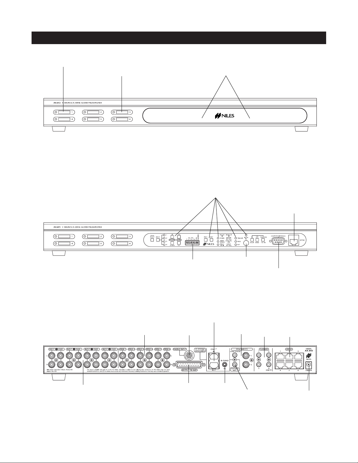
PARTS GUIDE (A4.6Ci)
LED Zone ON/OFF Indicator
Zone Label Slots
Removable Programming Cover
DB-9 Computer
Interface
Sensor for Capturing
IR Commands
Programming Controls
and Indicators
Connection for
Programming
Keypads
Zone All On/Page
Enable Switches
DB-9 Computer
Interface
Sensor for Capturing
IR Commands
Programming Controls
and Indicators
Figure 4 A4.6Ci Rear Panel
16V DC
Power Input
Keypad
Inputs
Flasher
Outputs
12V Control
Output
IR Input
Sync
Inputs
System
Expansion
DB25
Zone Audio
Output
Paging
Input
Audio Inputs
with Buffered
Cascade Outputs
Zone Audio
Outputs
Figure 2 A4.6Ci Front Panel with Programming CoverFigure 2 A4.6Ci Front Panel with Programming Cover
Figure 3 A4.6Ci Front Panel with Programming Cover Removed
Page 10

LED Zone ON/OFF Indicators
Provides individual ON/OFF indication for each
zone.
Zone Label Slots
Coined slots for placing included room labels,
providing zone identification.
Removable Programming Cover
Conceals installer-programming controls.
Programming Controls and Indicators
Push buttons and LED prompts for system and IR
programming.
Zone ALL ON/PAGE Enable Switches
Individual DIP switches to enable or disable systemwide All ON commands and the paging feature for
particular zones.
Sensor for IR Capture
IR sensor for capturing IR commands for control of
the connected source components.
DB-9 Computer Interface
PC connection enabling program configuration backup/downloading.
RJ-45 Connection for Programming Keypad
RJ-45 connection used for Master and Accessory Keypad
Modules providing manual system programming.
Zone Audio Outputs
Six pairs of stereo RCA jacks provide output connections for the external amplifier.
Paging Input
A mono RCA input for a paging signal from a
telephone system.
Flasher Outputs
Three 3.5mm jacks provide an output connection for
IRC-2P Micro Flashers, one for each connected
source component. A fourth is designed for the
IRC-1P Flood Flasher.
Keypad Inputs
Six female RJ-45 jacks are used for the connection of
the IntelliPad Ci Master Keypad Modules.
Audio Inputs with Buffered Cascade Output
Four pairs of stereo RCA jacks provide input connections for source components. Each input has a
respective buffered cascade output for distributing
audio signals for expanded systems.
DB25 Zone Output
A DB-25 Output Connector provides six zoned
stereo output signals using a single cable for connection to Niles Multi-Channel Amplifiers equipped with
a DB-25 Input Connector.
IR Input
A single 3.5mm jack provides an input connection
for IR commands sent from a Home Theater. These
IR commands are used for control of source equipment shared with an A4.6Ci.
12V Control Output
A single 3.5mm jack provides a 12V DC trigger
signal for use with voltage-triggered AC power strips
(i.e., Niles AC-3) to control source components
requiring activation via a switched AC outlet.
Sync Inputs
Video and voltage sensing inputs 1and 2 are for detecting when a source component is on/off for reliable
system activation. The HT Sync Input senses voltage,
determining the on/off status of a Home Theater that
shares source components with the A4.6Ci.
16V DC Power Input
Power connection for use with included AC-to-DC
in-line power adapter.
10
PARTS GUIDE (A4.6Ci)
Page 11
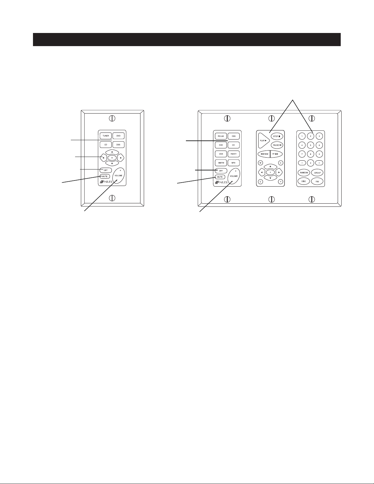
Solo™ Master
Keypad Module
11
PARTS GUIDE SOLD SEPARATELY
Master Keys
Function Keys
Zone OFF Key
Mute Key
Zone Volume Key
Master Keys
Zone OFF Key
Mute Key
Zone Volume Key
Function Keys
Transport™ Master
Keypad Module
Numeric™ Master
Keypad Module
Select™ Master
Keypad Module
IntelliPad Ci Keypad Modules
Figure 5
Master Keys
A quick tap of any of these keys turns on the zone and selects a source component. Pressing and holding
these buttons for longer than three seconds turns on all enabled zones. Also, all zones are selected to the
same source component.
Zone OFF Key
A quick tap of this Key turns your specific ZONE OFF. Pressing and holding this button for longer than three
seconds causes ALL ZONES to turn OFF.
Volume Keys
A continuous press of these buttons raises or lowers the volume in your specific ZONE. Pressing these buttons also restores sound in a muted zone.
Zone Mute Key
A quick tap of this button mutes the sound in a ZONE. A quick tap of this button restores sound in a muted zone.
Function Keys
Pressing these keys issues the individual IR commands programmed for control of the connected source
components.
Page 12
12
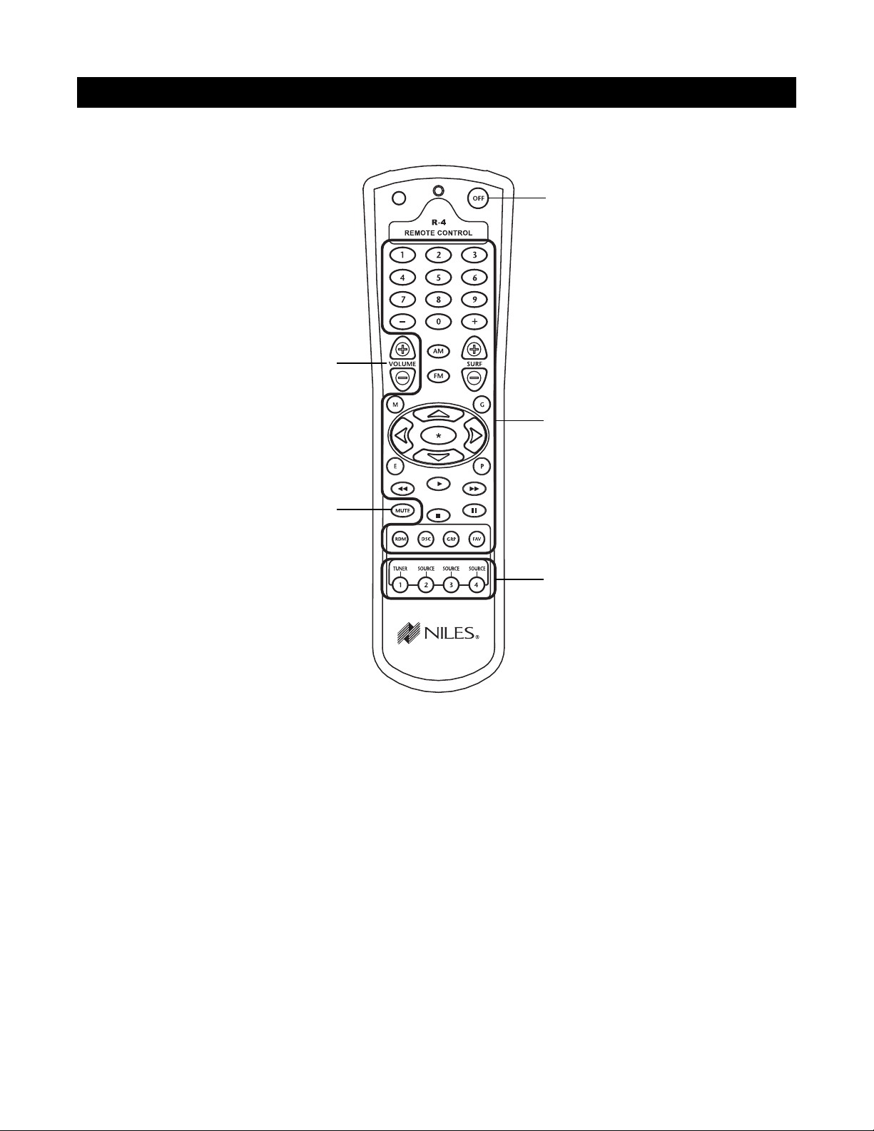
Source Buttons
A quick tap of any of these buttons turns on the zone and
selects a source component. Pressing and holding these
buttons for longer than three seconds turns on causes all
enabled zones. Also, all zones are selected to the same
source component.
Zone OFF Button
A quick tap of this button turns your specific zone off.
Pressing and holding this button for longer than three
seconds causes all zones to turn off.
Function Buttons
Pressing these buttons issues the individual IR commands programmed for control of the connected
source components.
Zone Volume Buttons
A continuous press of these buttons raises or lowers the
volume in your specific zone. Pressing these buttons
also restores sound in a muted zone.
Zone Mute Button
A quick tap of this button mutes the sound in a zone. A
quick tap of this button restores sound in a muted zone.
Figure 6
Zone Volume Buttons
Zone OFF Button
Function Buttons
Source Buttons
Zone Mute Button
PARTS GUIDE SOLD SEPARATELY
R-4 REMOTE
Page 13
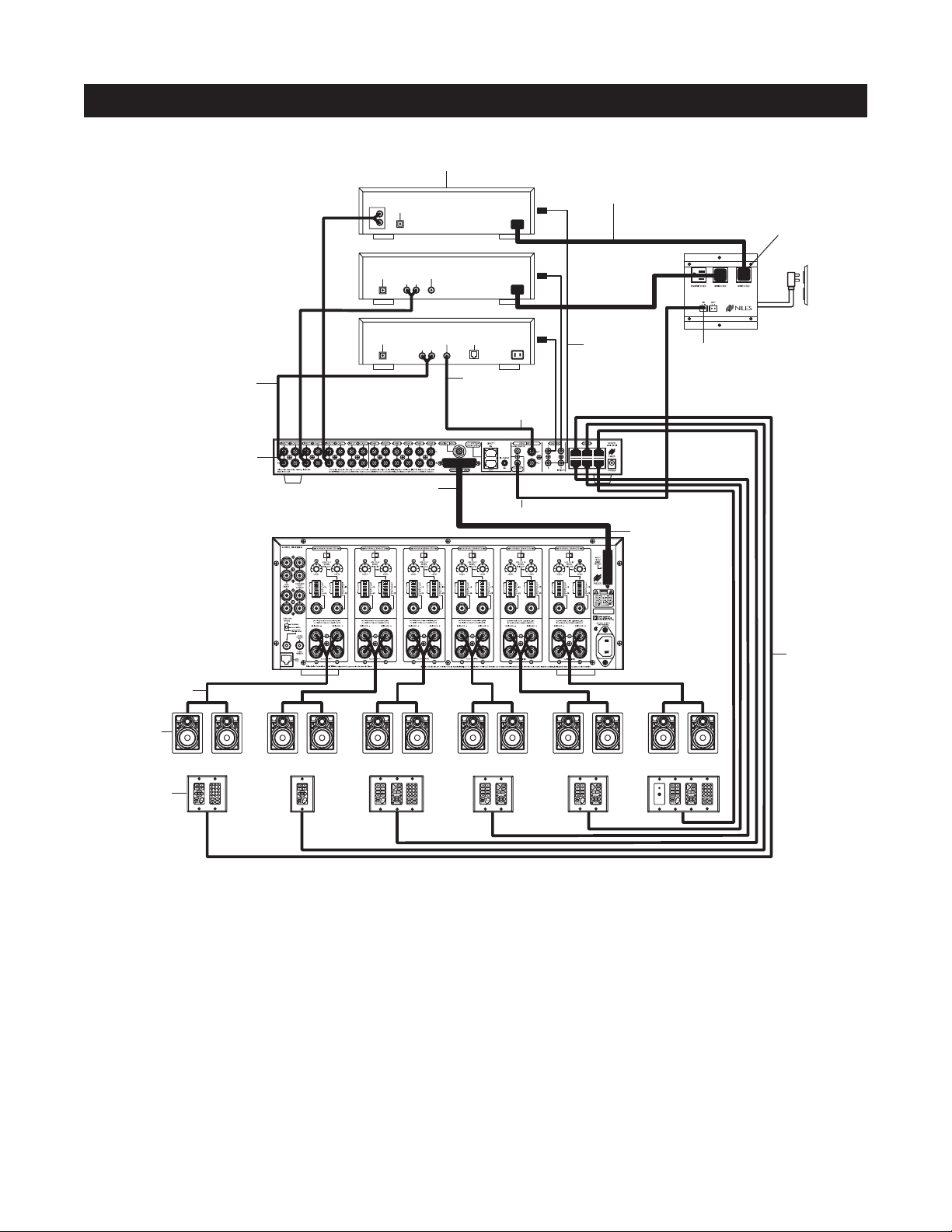
This is the simplest of the A4.6Ci configurations (see Figure 7). It depicts one Niles A4.6Ci MultiZone
Preamplifier installed to provide sound to six listening zones.
Each zone consists of one room with one pair of speakers. One Solo
™
Master Keypad Module or one Select
™
Master Keypad Module is included in each zone for user control. Numeric™Accessory Keypad Modules and/or
Transport
™
Accessory Keypad Modules and IR Sensors are added to specific zones as options.
Source Components
The A4.6Ci has RCA audio inputs for connecting four external source components for selection by each of the
six zones.
With this configuration, a user in one zone can listen to one source component while another user in a different
zone listens to a different source component (i.e., the CD can be selected in Zone 1 while the tuner is selected
in Zone 2). Additionally, each of the six zones can be set to an individual volume level. If more than one zone
chooses the same source component, IR control of that source component is shared between the zones.
13
CONFIGURATION 1 - SIX ZONES
SYSTEM CONFIGURATIONS
I
N
F
R
A
R
E
D
S
E
N
S
O
R
K
N
O
C
K
O
U
T
I
N
F
R
A
R
E
D
S
E
N
S
O
R
K
N
O
C
K
O
U
T
ZONE 1
I
N
F
R
A
R
E
D
S
E
N
S
O
R
K
N
O
C
K
O
U
T
I
N
F
R
A
R
E
D
S
E
N
S
O
R
K
N
O
C
K
O
U
T
ZONE 2
I
N
F
R
A
R
E
D
S
E
N
S
O
R
K
N
O
C
K
O
U
T
I
N
F
R
A
R
E
D
S
E
N
S
O
R
K
N
O
C
K
O
U
T
ZONE 3
I
N
F
R
A
R
E
D
S
E
N
S
O
R
K
N
O
C
K
O
U
T
I
N
F
R
A
R
E
D
S
E
N
S
O
R
K
N
O
C
K
O
U
T
ZONE 4
I
N
F
R
A
R
E
D
S
E
N
S
O
R
K
N
O
C
K
O
U
T
I
N
F
R
A
R
E
D
S
E
N
S
O
R
K
N
O
C
K
O
U
T
ZONE 5
I
N
F
R
A
R
E
D
S
E
N
S
O
R
K
N
O
C
K
O
U
T
I
N
F
R
A
R
E
D
S
E
N
S
O
R
K
N
O
C
K
O
U
T
ZONE 6
LR
AUDIO VIDEO
DSS
PHONE
DIGITAL
L
CD CHANGER
R
AUDIO
DIGITAL
LR
AUDIO VIDEO
DVD
DIGITAL
12V Trigger
Switched
AC Outlet
Unswitched
AC Outlet
Niles
AC-3
Keypads
Speakers
Speaker Cables
Audio Cables
Niles IRC-2P
MicroFlashers
AC Power Cord
Source Components
Four-Pair
Tw isted Cable
Zone Outputs
Niles SI-1260
Audio Inputs
12V Control Output
Sync Input
Video Output
Zone Inputs
Figure 7
Page 14

Keypads and IR Sensors
Keypads and IR sensors enable the user to control the Niles A4.6Ci MultiZone Preamplifier and its connected
source components. The source components’ IR commands are programmed into the Niles A4.6Ci MultiZone
Preamplifier. These commands are then triggered when the user presses a keypad button or issues a Niles IR
command to an IR sensor.
Each zone on the A4.6Ci has a corresponding RJ-45 keypad connector that is used to connect one Solo™ or
Select™ Master Keypad Module. Each Master Keypad Module can be mated with one optional Numeric™ or
Transport™ Accessory Keypad Module using an included jumper cable (see Connections). The Solo™ or Select™
Master Keypad Modules connect to the A4.6Ci with a "home run" of four-pair twisted cable, terminated with
RJ-45 connectors.
An IR Sensor can be included in any zone and connects directly to the Solo™or Select™Master Keypad Module
(see the Connections section of this manual for more details). A three-wire to RJ-45 adapter is available from Niles
(see Accessories) for IR Sensors installed with two-conductor shielded cable rather than four-pair twisted cable.
Adding an IR Sensor enables the Niles R-4 Accessory hand-held IR remote, or a learning remote control
programmed with Niles R-4 IR commands, to control the A4.6Ci and the connected source components. In
addition, a source component’s actual IR commands (i.e., provided by the component’s original remote control or a learning remote control programmed with these IR commands) can be used with the IR sensor to control the source components.
Important Note: The A4.6Ci does not provide individual operation of identical source components when using a source
component’s factory remote through an IR Sensor (see Identical Source Components on page 35 for more details).
Source-Component Automation
There are two methods of controlling the power ON/OFF of the source components.
1. Synchronized IR - In Figure 4, the DSS receiver’s power ON/OFF is synchronized via a video signal con-
nected to the A4.6Ci. When the Master Key/Source Button for the DSS is pressed, the A4.6Ci checks for a
video signal at the Sync Input corresponding to the DSS. The A4.6Ci issues the power command to turn the
DSS ON only when no video signal is present and the DSS is OFF.
When the Off Key/Button is pressed in a zone, the A4.6Ci checks to see if any other zones are on (including
the Home Theater zone sharing sources). The power command for turning the DSS OFF is issued only if that
zone is the last zone turning OFF in entire system and a video signal is present at the Sync Input corresponding to the DSS.
Important Note: RCA Sync Inputs also can detect 12V for use with Niles external sensing devices, (i.e., the
LS-1 Light Sensor and the APC-2 Current Sensing Device). See Source Power Synchronization on page 41 for
more information.
2. Latching Power - In Figure 4, AC power to the DVD and CD changer is turned on and off via the switched
AC outlets of a Niles AC-3. The AC-3 is activated by the 12V control output of the A4.6Ci when any one of the
six zones is ON (including the Home Theater Zone sharing sources).
Each Master Key on the Solo
™
and Select™Master Keypad Modules is programmable with a sequence of IR
commands for their respective source component. Commands included in the sequence are typically the Play
or Channel commands to start a source playing or to select a particular music or radio station after the source
has been selected.
Flasher Outputs
Niles IRC-2P MicroFlashers
™
connect to the numbered flasher outputs on the rear panel of the Niles A4.6Ci
MultiZone Preamplifier. Flashers send IR commands to the individual source components for control. An
IRC-1P Flooding Flasher can be connected to Flasher #4 to control more than one source component.
14
SYSTEM CONFIGURATIONS
Page 15
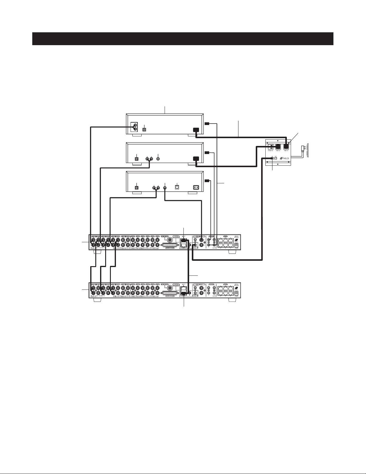
CONFIGURATION 2 – ADDING ZONES USING MULTIPLE A4.6Ci’s
More than one A4.6Ci MultiZone Preamplifier can be used if the system requires more than six zones. A maximum of four A4.6Ci’s (providing up to 24 zones) can be combined to create a larger multi-zone/multi-source
system. One A4.6Ci is designated as the Master and the others as Slaves (see Installation Settings on page 65
for more details).
In Figure 8, a four-pair twisted cable connecting the CiNet system expansion ports of the two A4.6Ci’s facilitates communication between the two. This communication enables all zones, provided by both A4.6Ci’s, to
obtain control of the shared source components (which are always connected to the Master). Also, system-wide
commands can be issued from any zone (i.e., All Zones ON/OFF).
Sharing Source Components with Multiple A4.6Ci’s
The Niles A4.6Ci MultiZone Preamplifiers share the audio signal from the source components via the buffered
cascade audio outputs provided, one for each of the four audio inputs.
Source-component control is accomplished via the programming in the Master A4.6Ci. All Slave A4.6Ci’s in
the system are left unprogrammed except for Zone On/Off Sequences and the required function key IR programming to create these sequences.
All Flasher and Sync Input connections for the shared source components are made to the Master A4.6Ci.
Keypad/Source Button commands and zone On/Off status are communicated to the Master A4.6Ci using the
CiNet system expansion in/out connections, providing coordinated control of all source components.
15
SYSTEM CONFIGURATIONS
Figure 8
Source Components
Designated
as the Master
Designated
as the Slave
AUDIO
L
R
DIGITAL
DIGITAL
DIGITAL
CD CHANGER
AUDIO VIDEO
LR
AUDIO VIDEO
LR
DVD
DSS
PHONE
Ci Net
Input
AC Power Cord
Niles IRC-2P
MicroFlashers
Four-Pair Twisted Cable
Niles
AC-3
12V Trigger
Switched
AC Outlet
Unswitched
AC Outlet
Ci Net
Output
Page 16
16
SYSTEM CONFIGURATIONS
Figure 9
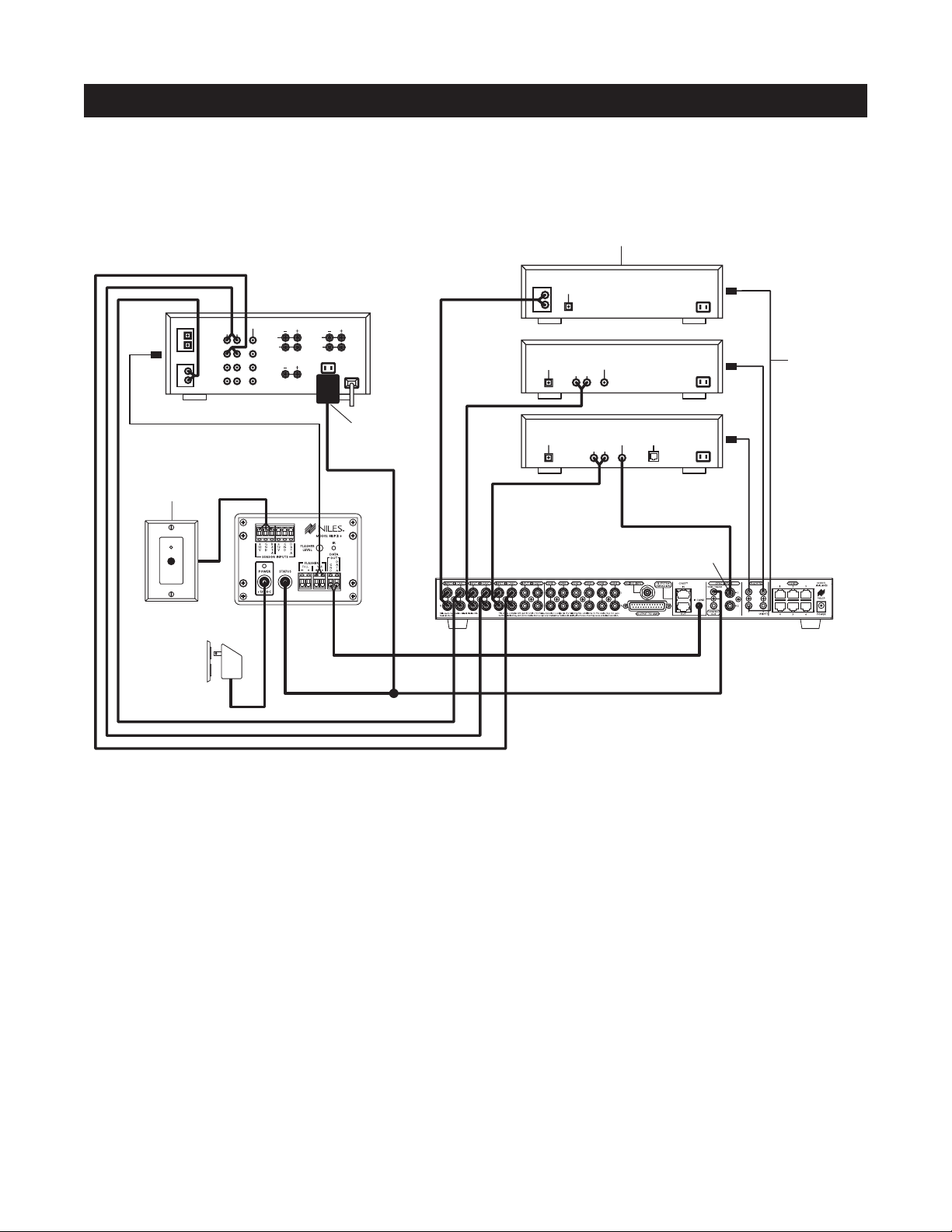
CONFIGURATION 3 – INTEGRATING AN IR-CONTROLLED HOME THEATER
An IR-controlled Home Theater receiver/processor can be integrated to share source components in a system
with a Master A4.6Ci.
Distributing Audio Signals
Audio signals for the shared source components are connected to both the A4.6Ci and the Home Theater receiver using
the buffered cascade audio outputs (Figure 9).
Shared Source Component Control
The DATA output from the Home Theater IR repeater (the IRP-2+ in Figure 9) is connected to the IR Input of the Master
A4.6Ci. The Home Theater IR Remote Control is now able to control the shared source components.
A 12V Sync signal is provided from the Home Theater to the Home Theater Sync Input to provide the A4.6Ci with the
On/Off status of the Home Theater. This status enables the A4.6Ci to provide coordinated control of the source component's power On/Off.
Important Note: When issuing the source component’s actual IR commands from the Home Theater Remote Control, all
IR commands are passed through to all source-component flasher outputs. Identical brand and model source components
cannot be operated individually using these commands. (For more information on controlling identical brand and model
source components, refer to the Operation Overview on page 28.)
Source Components
AUDIO
DIGITAL
DIGITAL
1
2
L
R
Video 1
Video 2
DVD
DSS
AUDIOCDVIDEO
LR
Home Theater Receiver
REAR
FRONT
L
L
R
R
CENTER
12V
D.C.
L
R
DIGITAL
CD CHANGER
DVD
AUDIO VIDEO
LR
Niles IRC-2P
MicroFlashers
Plugged into
Switched
AC Outlet
DIGITAL
DSS
AUDIO VIDEO
LR
PHONE
Niles IR Sensor
located in
Home Theater
Niles
IRP2+
H.T. Sync Input
Plugged into
Unswitched
AC Outlet
12V
D.C.
Page 17
17
SYSTEM CONFIGURATIONS
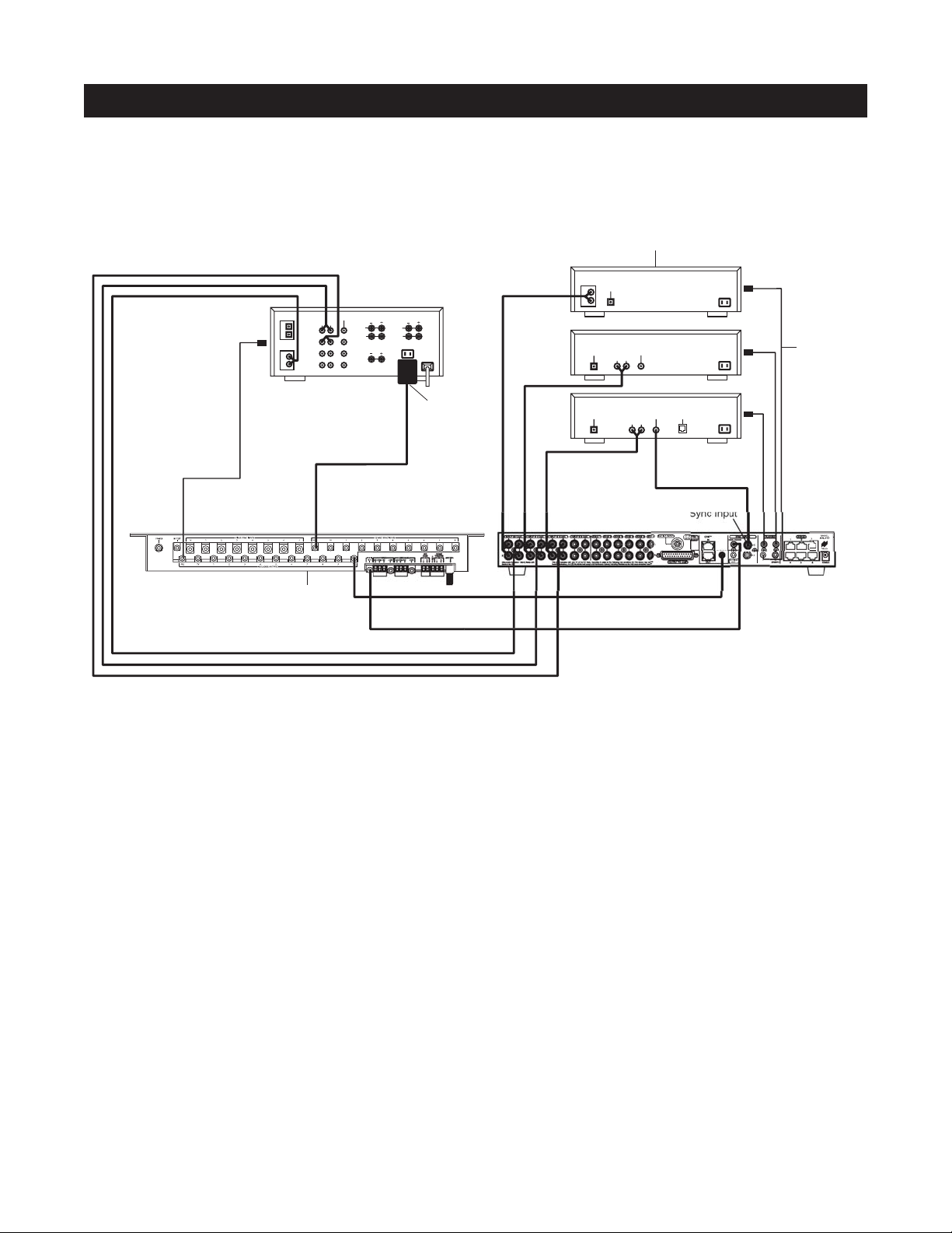
CONFIGURATION 4 – INTEGRATING A HOME THEATER USING AN INTELLICONTROL
A Home Theater system controlled by a Niles IntelliControl®can be integrated to share source components in a system with the A4.6Ci.
Distributing Audio Signals
Audio signals for the shared source components are connected to both the A4.6Ci and the Home Theater receiver
using the buffered cascade audio outputs (Figure 10).
Shared Source Component Control
The FLASHER output from the IntelliControl (Figure 10) is connected to the IR input of the A4.6Ci. The
IntelliControl, programmed with Niles Remote IR commands, is now able to automate and control the shared
source components. Niles IR commands are taught to the IntelliControl using the A4.6Ci and an attached flasher or the R-4 Remote itself (see Programming Overview for more details on page 45).
A12V Sync signal is provided from the IntelliControl to the Home Theater Sync Input to provide the A4.6Ci
with the On/Off status of the Home Theater. This status enables the A4.6Ci to provide coordinated control of
the source component's power On/Off.
Important Note: When issuing the shared source components’ actual IR commands from the Home Theater
Remote Control, all IR commands are passed through to all shared source component flasher outputs. Identical
brand and model source components cannot be operated individually using these commands. (For more information on controlling identical brand and model shared source components, refer to the Operation
Overview on page 28.)
H.T. Sync Input
SU
Figure 10
Source Components
AUDIO
DIGITAL
L
R
DIGITAL
CD CHANGER
DVD
AUDIO VIDEO
LR
Niles IRC-2P
MicroFlashers
DIGITAL
1
2
L
R
Video 1
Video 2
DVD
DSS
Home Theater Receiver
AUDIOCDVIDEO
LR
L
R
CENTER
FRONT
REAR
L
R
12V
D.C.
IntelliControl M
Plugged into
Switched
AC outlet
DIGITAL
DSS
AUDIO VIDEO
LR
PHONE
Page 18
18
CONFIGURATION 5 – MULTIPLE MASTER KEYPAD MODULES IN A ZONE
The single zone of a Niles A4.6Ci MultiZone Preamplifier can be expanded to contain multiple Solo
™
and
Select
™
Master Keypad Modules, providing control from many locations within the zone. A Niles IntelliPad®Ci
Expander
™
is required to connect multiple keypads in a single zone. A maximum of five Solo™Master Keypad
Modules can be included in a single zone using two Expanders.
In Figure 11, two Solo
™
Master Keypad Modules are installed on either side of a bed. When connected, all
keypads in a zone work in tandem with one another (i.e., all control the same zone and display the same Zone
ON/OFF, Mute, and Input Select Status).
SYSTEM CONFIGURATIONS
Figure 11
Niles
Niles SI-1260
DB-25
Cable
IntelliPad
®
Ci Expander
OUTPUT
INPUTS
2
1
3
POWER
™
Unswitched
AC Outlet
Power
Supply
Four-Pair
Twisted Cable
Keypads
Two-Conductor
Speaker Cable
Bed
ZONE 6
(Bedroom)
C
K
O
O
N
U
K
T
I
N
R
F
O
R
S
A
N
R
E
E
S
D
C
K
O
O
N
U
K
T
I
N
R
F
O
R
S
A
N
R
E
E
S
D
Speakers
Page 19
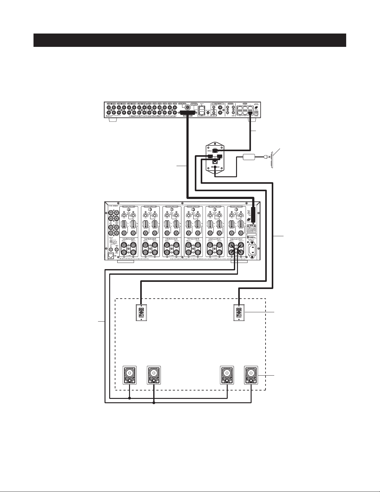
CONFIGURATION 6 – MULTIPLE LISTENING AREAS IN A ZONE
A single zone of the A4.6Ci MultiZone Preamplifier can be set up to contain more than one listening area (i.e., an adjacent living room and dining room). This configuration is chosen when the speakers in the zone are not required to play at
separate volume levels or to be on/off separately.
In Figure 12, a speaker cable is connected to the speaker outputs of Zone 3 and then parallel-connected to the
speakers in both the living room and the dining room. A Solo
™
Master Keypad Module is located in each area.
A Niles IntelliPad
®
Ci Expander™is required to connect the two Solo™Master Keypad Modules in a single zone.
When connected, all keypads in a zone work in tandem with one another (i.e., all control the same zone and
display the same Zone ON/OFF, Mute, and Input Select Status).
19
SYSTEM CONFIGURATIONS
Figure 12
Niles SI-1260
DB-25
Cable
IntelliPad
Niles
®
Ci Expander
OUTPUT
INPUTS
2
1
3
POWER
™
Power
Supply
Four-Pair
Twisted Cable
Unswitched
AC Outlet
Four-Pair
Twisted Cable
Keypads
Two-Conductor
Speaker Cable
ZONE 6
(Living / Dining Room)
Living Room
C
K
O
O
N
U
K
T
I
N
R
F
O
R
S
A
N
R
E
E
S
D
C
K
O
O
N
U
K
T
I
N
R
F
O
R
S
A
N
R
E
E
S
D
Dining Room
C
K
O
O
N
U
K
T
I
N
R
F
O
R
S
A
N
R
E
E
S
D
C
K
O
O
N
U
K
T
I
N
R
F
O
R
S
A
N
R
E
E
S
D
Speakers
Page 20
20
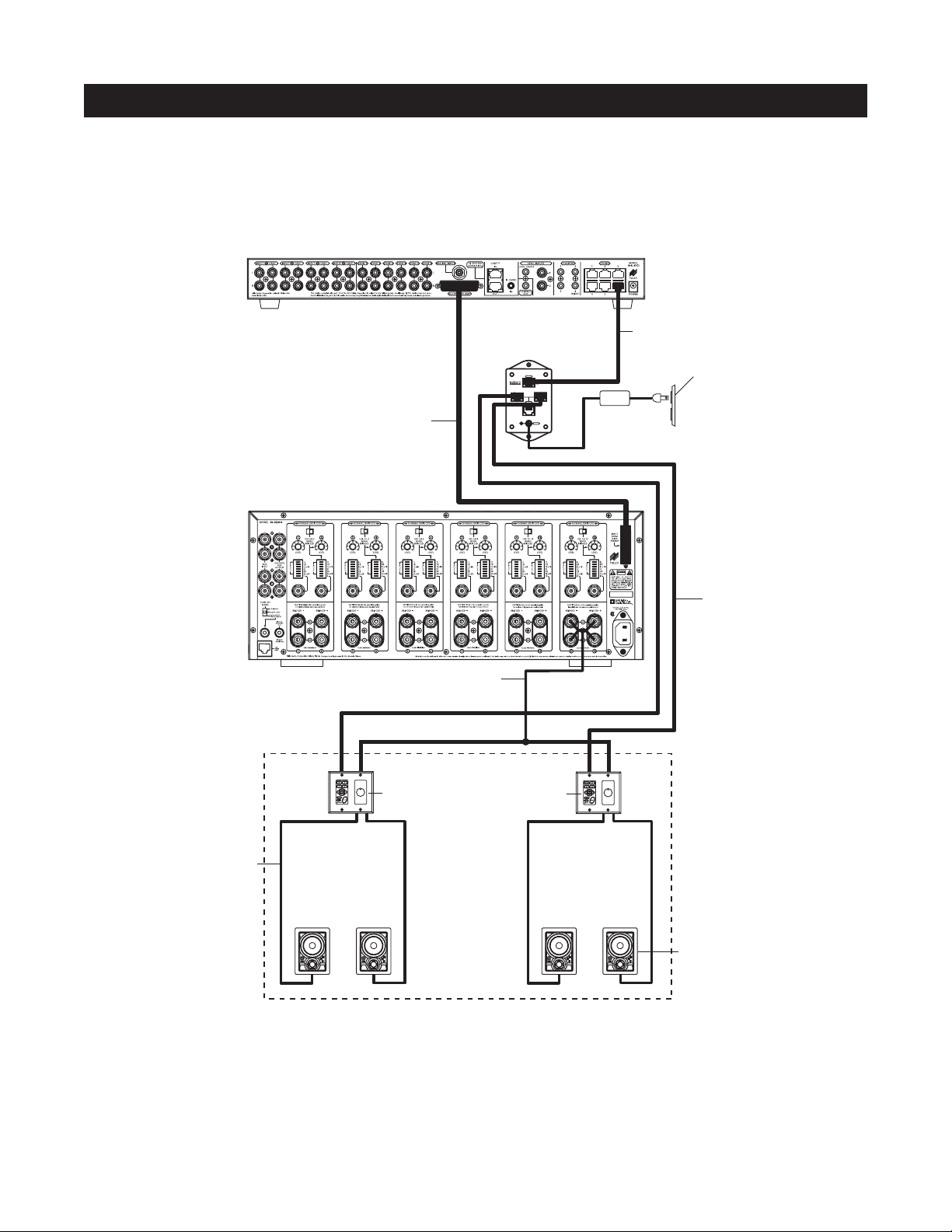
CONFIGURATION 7 – MORE THAN ONE ROOM IN A ZONE
A zone can be divided up into as many as five individual rooms with separate On/Off and Volume controls.
A Niles Silencer Volume Control located along with the Master Keypad in each room is required in addition
to Niles Expanders.
In Figure 13, Zone #6 has been expanded into two rooms that can be On/Off individually and be set at different
volume levels. Impedance magnification is incorporated in the Silencer to enable the safe connection of multiple
pairs of speakers to a single zone amplifier. Connection of three rooms with Master Keypads and Silencers to a
single zone of the A4.6Ci is accomplished with a single Niles Expander. Five rooms is accomplished using two
Expanders (see the Expander manual for more details).
SYSTEM CONFIGURATIONS
Figure 13
Niles SI-1260
DB-25
Cable
Four-Conductor
Speaker Cable
IntelliPad
Niles
®
Ci Expander
OUTPUT
INPUTS
2
1
3
POWER
™
Power
Supply
Four-Pair
Tw isted Cable
Unswitched
AC Outlet
Four-Pair
Tw isted Cable
Silencer
ZONE 6
Keypad
Tw o-Conductor
Speaker Cable
Master Bedroom Master Bathroom
C
K
O
O
N
U
K
T
I
N
R
F
O
R
S
A
N
R
E
E
S
D
C
K
O
O
N
U
K
T
I
N
R
F
O
R
S
A
N
R
E
E
S
D
C
K
O
O
N
U
K
T
I
N
R
F
O
R
S
A
N
R
E
E
S
D
C
K
O
O
N
U
K
T
I
N
R
F
O
R
S
A
N
R
E
E
S
D
Speakers
Page 21
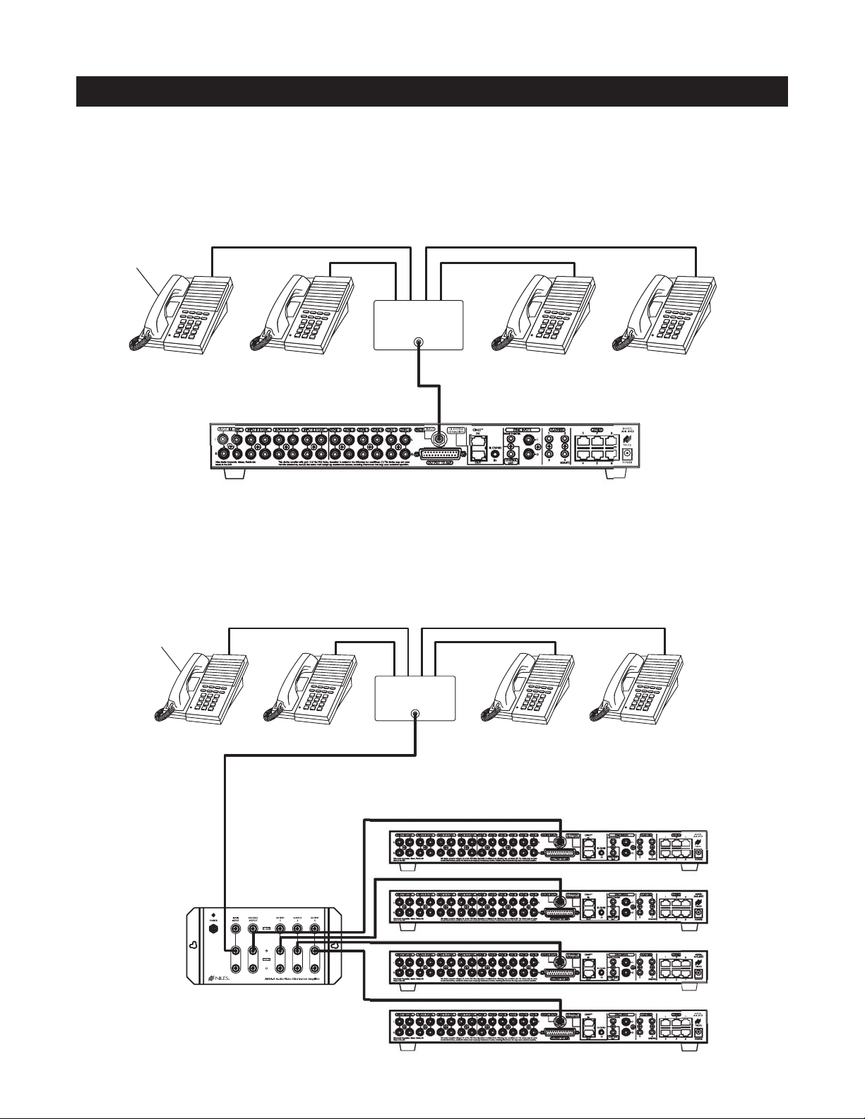
CONFIGURATION 8 – SYSTEM PAGING WITH AN EXTERNAL TELEPHONE SYSTEM
A Paging Input connection is provided on the rear panel of the A4.6Ci. It provides a connection for the paging
output signal of popular telephone systems for voice paging through the speakers located in the listening zones
(see Figure 14).
A Niles AVDA-3 (see Figure 15) is required when connecting a telephone system to two or more A4.6Ci’s in
larger systems.
21
SYSTEM CONFIGURATIONS
Figure 14
Figure 15
System
Telephones
Telephone
Control Unit
PAGE OUTPUT
System
Telephones
Telephone
Control Unit
PAGE OUTPUT
Niles AVDA-3
Distribution Amplifier
Page 22
22
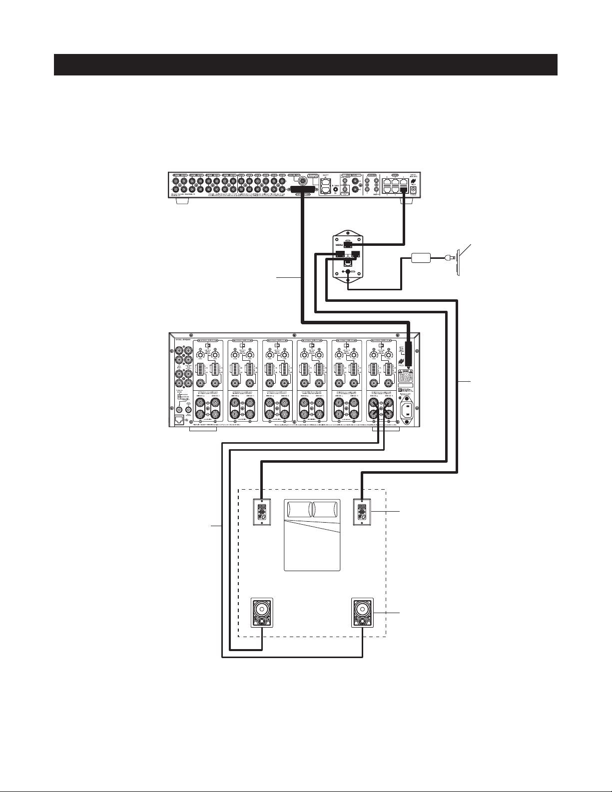
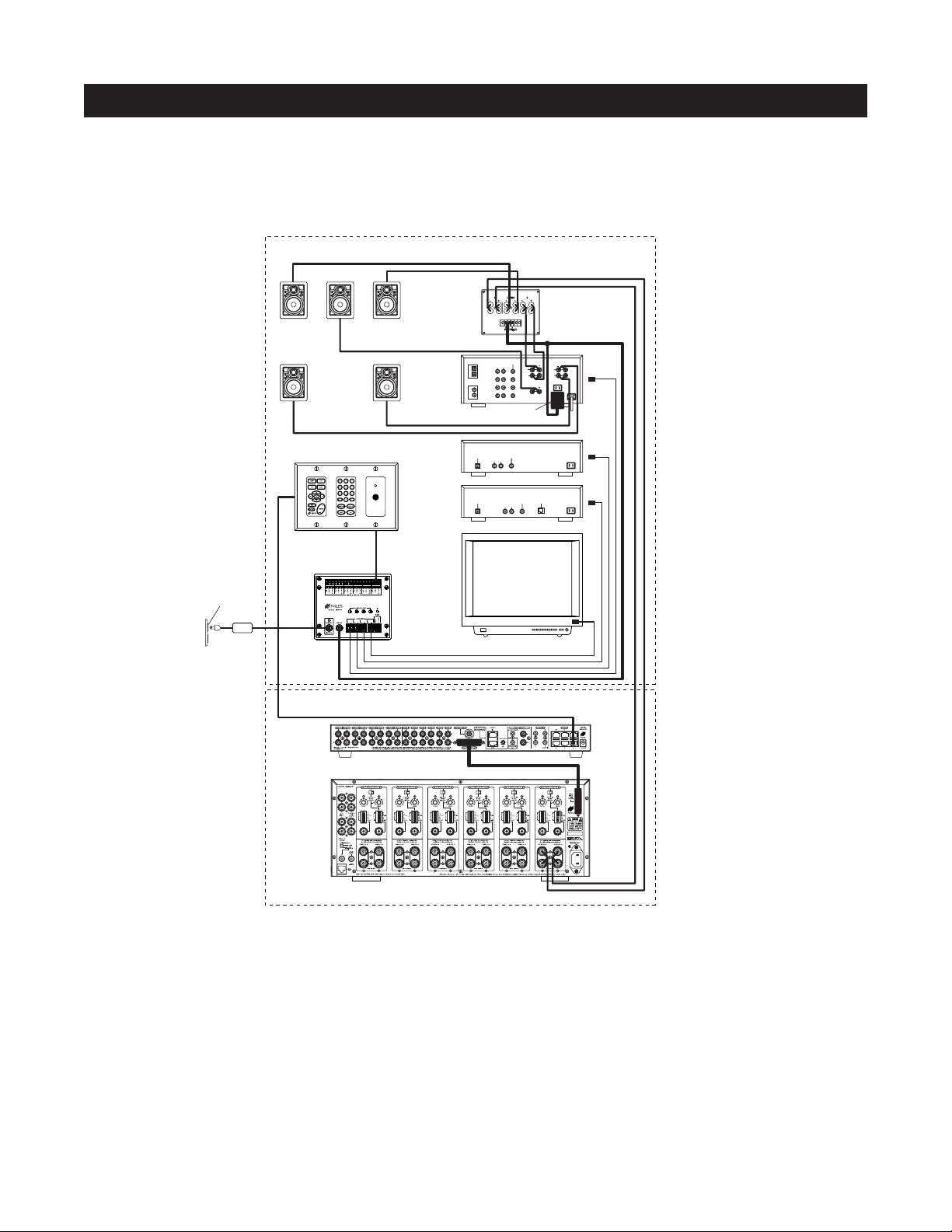
CONFIGURATION 9 – IR REPEATING FOR CONTROL OF LOCAL COMPONENTS
An IR Repeating System can be integrated into a room connected to the Niles A4.6Ci (see Figure 16). This enables
a single IR Sensor (installed in that room) to control local components with a hand-held IR remote control.
In Figure 16, a Niles IR Sensor is connected to a Niles IRP-6+ for control of local components and to a Niles
A4.6Ci for control of distributed components. A Niles SPK-1 Automated Speaker Level A-B Switcher switches
the front speakers in the master bedroom from the A4.6Ci distributed sound system to the local surround-sound
receiver system when the local system is activated. (See the Installation section of this manual for details on the
required connections for the IRP-6+ and the SPK-1.)
Important Note: Use of an identical brand and type component in both the local and the distributed system
(i.e., a Sony CD player in both systems) is not supported by this configuration. Individual operation of identical components may not be possible (refer to Connections section).
Audio signals for the shared source components are connected to the Home Theater receiver using the cascade
audio outputs.
SYSTEM CONFIGURATIONS
Figure 16
Zone 6 – Master Bedroom
Center
D
D
D
S
E
E
R
N
A
S
R
O
F
R
N
I
T
K
U
N
O
O
K
C
S
E
E
R
N
A
S
R
O
F
R
N
I
T
K
U
N
O
O
K
C
Niles SPK-1
Right
Front
DIGITAL
AUDIO
VIDEO
LR
1
DVD
D
S
E
E
R
N
A
S
R
O
F
R
N
I
T
K
U
N
O
O
K
C
2
Video 3
CD
Video 2
L
R
Video 1
Plugged into
Switched AC outlet
REAR
FRONT
L
L
R
R
CENTER
12V
D.C.
Left
Front
S
E
E
R
N
A
S
R
O
F
R
N
I
T
K
U
N
O
O
K
C
D
S
E
E
R
N
A
S
R
O
F
R
N
I
T
K
U
N
O
O
K
C
Rear
Speakers
Unswitched
AC Outlet
Power
Supply
Niles Keypads / IR Sensor
Niles IRP-6+
Niles SI-1260
DVD
AUDIO VIDEO
DIGITAL
LR
DSS
DIGITAL
AUDIO VIDEO
LR
PHONE
TV
Distributed Equipment Location
Page 23

INFRARED COMMAND COMPATIBILITY
IR control testing was conducted on many equipment brands to determine their compatibility with the A4.6Ci.
Typical A/V source components (i.e., CD, DVD, DSS, Cable Boxes, etc.) from each brand were chosen for the
test. All brands listed below passed the test.
Important Note: Use this list only as a starting point. All the components for every brand listed were not available at the time of testing. To avoid unforeseen incompatibilities, Niles recommends always testing components
you have not yet used with a A4.6Ci prior to specifying them in your installation.
Testing for a Possible IR Command Conflict
When using a Niles IRC-1P FloodFlasher,
™
there are rare instances when the same IR command will operate more
than one source component. This prevents the proper operation of another IR controlled component when the
two are installed in the same system because the press of a single remote button causes both components to
respond. Rare as this situation is, when working with unfamiliar equipment or two products that you have never
combined in the same system, it is advisable to first test how these components interact with each other.
To test for this type of conflict, take all the remotes in the system and issue every command you will be programming in the keypads. Expose all components to each command and make sure that only the appropriate
component responds.
Solving the IR Command Conflict if Present
Remember that conflicts of this nature are rare. However, if you find yourself in this situation, contact the manufacturers to ask if they are aware of the problem and if they have a solution. Perhaps they now have a different
remote, or a chip upgrade for the product.
If the manufacturers do not have a solution, the problem may be resolved by using a Niles IRC-2P
MicroFlasher
™
instead of IRC-1P FloodFlasher.™In cases where neither solution works, advise the client of the
situation and explain that you must substitute another component.
23
COMPONENT COMPATIBILITY
Adcom
APEX
B&K
Denon
Echo Star
Escient
Go Video
Harman Kardon
Hitachi
Hughes
Jerrold
JVC
Kenwood
Krell
Lexicon
Lightolier
Lutron
Magnavox
Marantz
McIntosh
Meridian
Mitsubishi
Motorola
NAD Electronics
Nakamichi
Niles
Onkyo
Panasonic
Parasound
Philips
Pioneer
RCA
Rotel
Samsung
Scientific Atlanta
Sharp
Sherwood
Sony
Te ac
Technics
To shiba
Yamaha
Zenith
Page 24

24
WHAT IS SOURCE-POWER SYNCHRONIZATION?
The A4.6Ci has been designed to keep track of the ON/OFF condition of the three source components connected to
the system. This allows you to automate source components that utilize the same IR command for ON and OFF.
For this feature to function as designed, you need synchronization (sync) between the A4.6Ci and source components that utilize the same IR command for ON and OFF. This assures the users of the system that the A4.6Ci
will always issue power commands correctly when they press a Master Key or the Off Key.
Source Power Sync makes it possible for users to always have a source component turn ON when they need
it on and to always have all the components turn OFF when they turn the system off.
Source Components that Require Power Synchronization
Source components that utilize the same IR command for ON and OFF need to be synchronized. The power
button for these source components sends the same IR command to turn the source components ON if they are
OFF, and to turn them OFF if they are ON. It is necessary to “synchronize” these source components with the
A4.6Ci so it knows not to send an ON command if the source components are already ON (if it did, the source
components would turn OFF, which is not the desired result). Conversely, synchronization keeps the A4.6Ci from
issuing a “power” command when the OFF Key is pressed, if the source components are already OFF.
The A4.6Ci has three Sync Inputs for each of the source components. It allows synchronization via voltage and video
signals. (see Choosing a Synchronization Method on page 25 for more information on how to synchronize components).
Source Components that Do Not Require Synchronization
Two types of components do not require synchronization: Those with separate ON and OFF IR commands and
those with “latching power.”
Source Components with Separate ON/OFF IR Commands
Synchronization is not required for source components that are included with and respond to separate ON and
OFF IR commands. When power commands are programmed as separate ON and OFF, the A4.6Ci will issue
ON commands only if sync is not present. Separate OFF commands for source components are always issued
when the last zone turns OFF regardless of sync status.
Source Components with “Latching Power”
Some source components, Such as CD players and tape decks, usually are plugged into the switched AC outlet of the preamplifier/receiver with which they are installed. These components simply turn ON when the system’s receiver/preamplifier turns ON, meaning that they “latch” into an ON or OFF state and do not need an
IR command to turn ON or OFF.
Because they turn ON as soon as there is power on their AC cord, once the preamplifier/receiver is turned on,
these components will turn on as well. They do not need individual synchronization.
Since the A4.6Ci does not provide a switched AC outlet, the 12V control output connected to a voltage-triggered
AC power strip (i.e., Niles AC-3) provides perfect control of latching source component. (See Configuration 1 in
the Systems Configurations section of this manual for more information.)
SOURCE-POWER SYNCHRONIZATION
Page 25
CHOOSING A SYNCHRONIZATION METHOD
Once you establish that all source components in the system have compatible IR commands, the next step is
to choose the appropriate sync method for each component.
There are two ways to detect when a component is ON or OFF: Video or Voltage Sync.
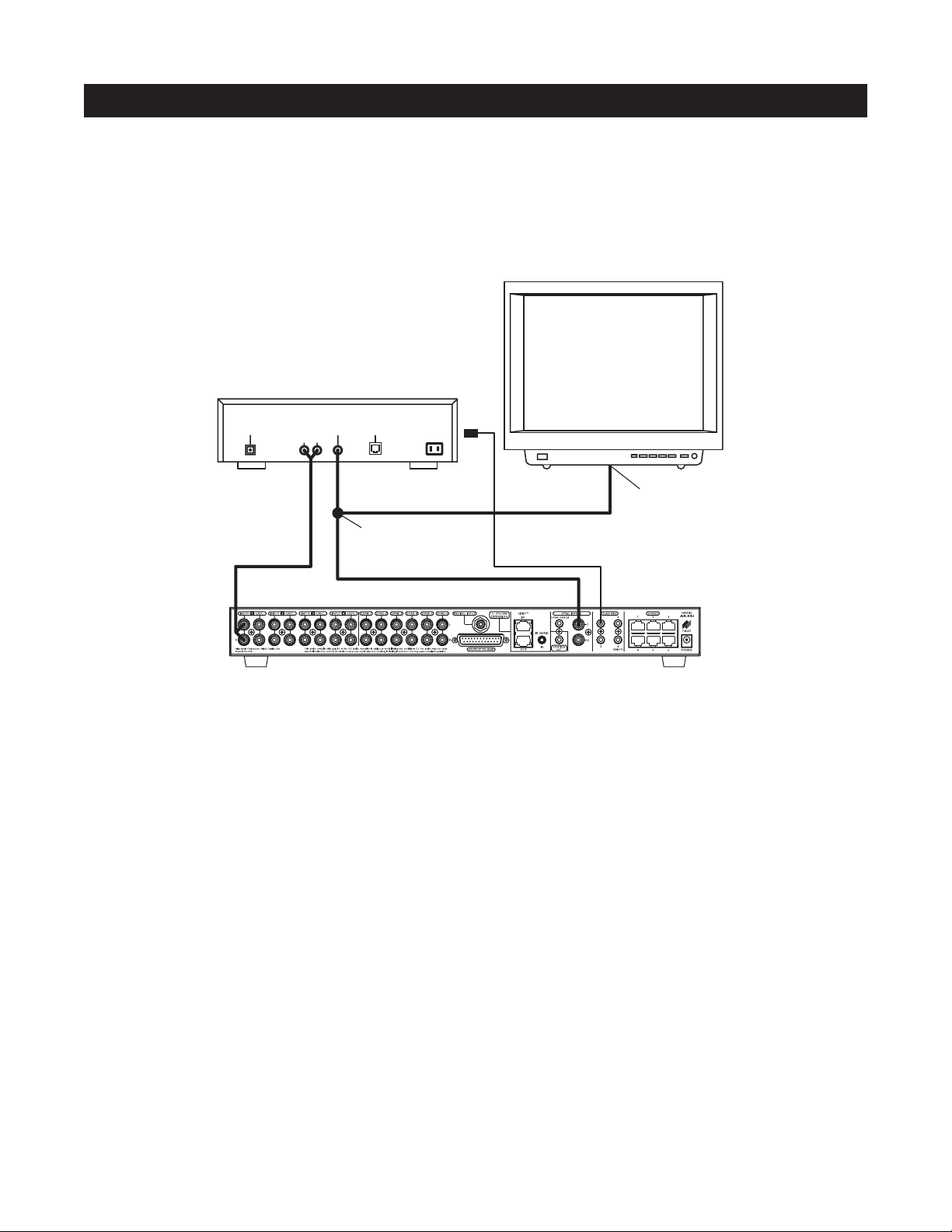
Video Sync
Video sync is the easiest and most reliable method of synchronization. Most video sources have a video output active only when the device is ON. This type of video output provides an excellent method for component
synchronization.
The A4.6Ci has three 12V Video Sync connections for synchronizing as many as three source components. In
Figure 18, the video output of a DSS is connected to both a TV and the corresponding sync input for the DSS using
an RCA Y-adapter. Picture quality will be unaffected due to the high impedance of the sync input.
If the source component has two video outputs, the need for an RCA Y-adapter is eliminated. Simply connect
the first video output to its normal system destination, and the second video output will be dedicated for the
sync input.
25
SOURCE-POWER SYNCHRONIZATION
Figure 18
TV
DIGITAL
AUDIO VIDEO
LR
PHONE
RCA Y-Adapter
Splitting Video Output
Video Input
DSS
Page 26
26
Voltage Sync
Voltage sync is also a reliable method of synchronization if chosen and implemented correctly. The sync inputs
can detect the control out voltage from a Niles signal-sensing product interfaced to the source component.
Obtaining Voltage Sync
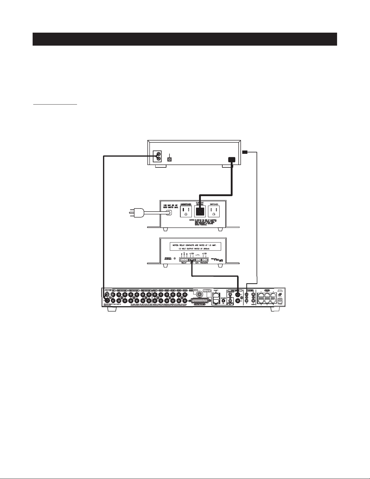
Current Sensing
Current Sensing synchronizes a component by detecting the changes in the AC power draw that occurs with a
component when it turns ON and OFF.
In Figure 19, a Niles APC-2 Current Sensing Switch senses the change in power consumption of a CD changer
when it is turned ON. When it senses that change, it outputs a 12V DC signal. The synchronized CD changer’s
AC power plug is connected to the current sensing outlet on the APC-2. The APC-2’s 12V DC output is connected to the A4.6Ci’s sync input dedicated to the CD changer, using a Niles 10’ bare wire to mini-plug accessory
cable (FG00724, see Accessories for more details).
When using a Niles APC-2, a minimum change of 30W is required for reliable current sensing. If the component does not have a 30W change in current draw when turning ON (i.e., DSS receivers and most VCRs and
CD players), consider the last method, Light Sensing.
SOURCE-POWER SYNCHRONIZATION
Figure 19
AUDIO
DIGITAL
L
R
CD CHANGER
Back
Niles APC-2
Front
Page 27
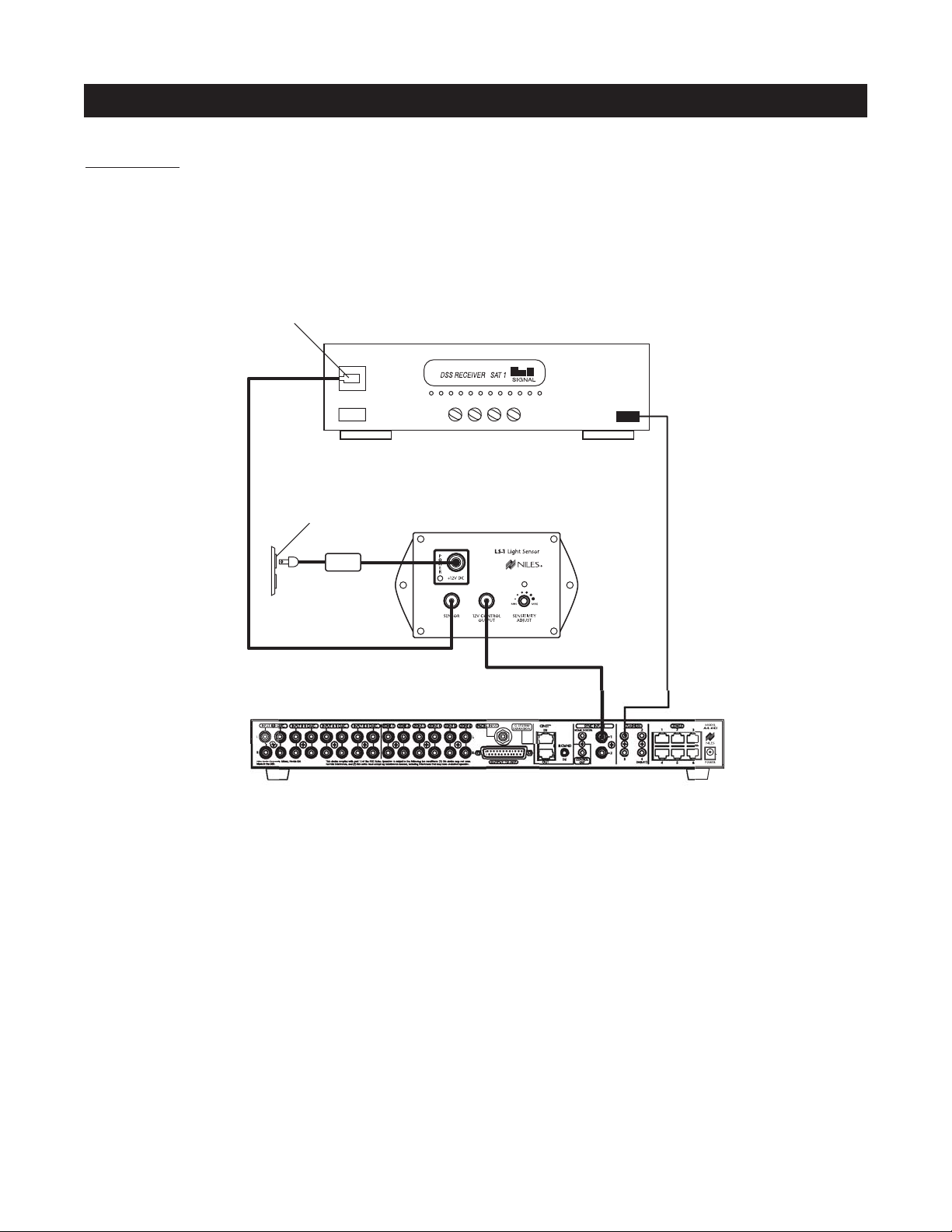
Light Sensing
Using a light sensor (LS-1) to synchronize your components is usually your last choice, simply because the other
choices are more reliable. The Niles LS-1 Light Sensor can synchronize a component by sensing changes in light.
The 12V output of the LS-1 is then connected to the A4.6Ci’s sync input dedicated for that component. A miniplug to RCA adapter is required for this connection (see Connections for more information).
In Figure 20, a Niles LS-1 Light Sensor senses changes in brightness of a DSS’s front-panel LED and outputs a
12V DC signal when the LED is brightest. A blocking cover prevents ambient light from falsely triggering the
LS-1.
An unused optical digital output on the rear panel of a digital source component also can provide a light source
for sync using the LS-1.
SOURCE AND HOME THEATER SYNC STATUS
Sync status (the presence or absence of a valid sync signal) of source components and the Home Theater
associated with the Master A4.6Ci are displayed on the LEDs located in the hidden programming panel. These
LEDs illuminate only while a valid sync signal is being received by the A4.6Ci during normal operation mode.
Source 2, Source 3, and Source 4 LEDs represent Source 2, Source 3, and Source 4 respectively. The Tuner LED
represents the Home Theater. These status LEDs are used during system troubleshooting. Manually turning
ON/OFF synchronized source components and the integrated Home Theater will turn ON/OFF the respective
component’s status LED if synchronized correctly.
27
SOURCE-POWER SYNCHRONIZATION
Figure 20
Light Sensing Probe
placed over an LED
DSS
Unswitched
AC Outlet
Power Supply
Niles LS-1
Page 28
28
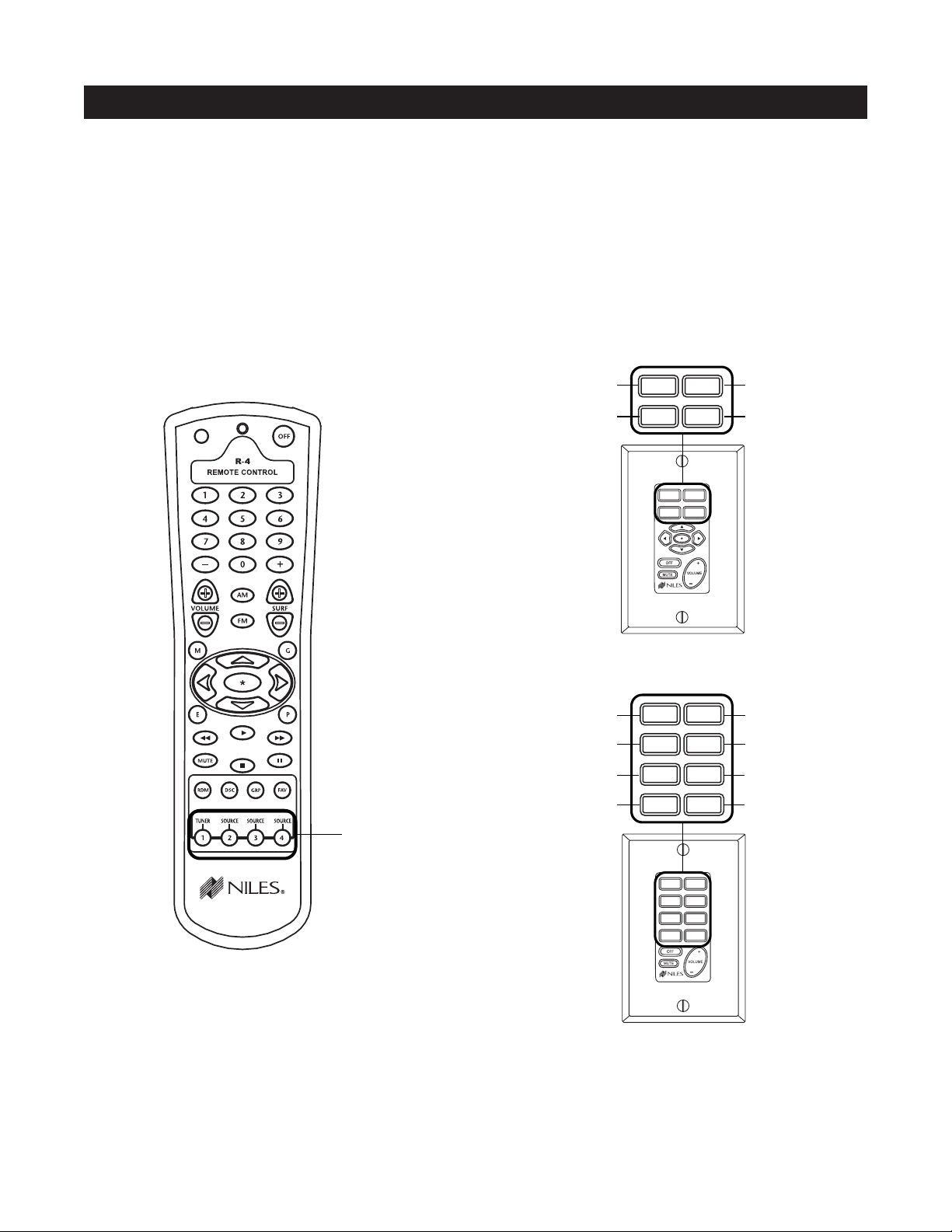
MASTER KEYS/SOURCE BUTTONS
The Master Keys available on the Solo
™
and Select™Master Keypad Module and the Source Buttons on the
hand-held R-4 Remote accessory (Figure 21) provide "one-touch activation" of the A4.6Ci and its connected
source components.
The Master Keys on the Solo and Select Master Keypad Modules are equipped with back-lit LEDs for indicating Zone ON/OFF, Zone Mute, and Zone Input Selection status.
The Source Buttons on the R-4 Remote correspond to the Master Keys on the Solo Master Keypad Module
(Master Key 1 = Tuner, Master Key 2 = Source Button 2, Master Key 3 = Source Button 3, and Master Key 4 =
Source Button 4).
The eight available Master Keys and their corresponding four Source Buttons are individually programmable.
Once programmed, they operate the system identically in each zone. Note: Master Keys on the Solo and Select
Master Keypad Module should be labeled the same in each zone.
OPERATIONAL OVERVIEW
Source Buttons on
the Hand-Held R-4
Remote Accessory
Figure 21
Master Keys on the Solo
™
Master Keypad Module
Master Key #2
Master Key #4
Master Key #1
Master Key #3
DVD
TUNER
CD DSS
DVD
JAZZ ROCK
BLUES
POP
TUNER
CD
DSS
Master Keys on the Select
™
Master Keypad Module
Master Key #2
Master Key #4
Master Key #1
Master Key #3
DVD
JAZZ ROCK
BLUES
POP
TUNER
CD
DSS
Master Key #6
Master Key #8
Master Key #5
Master Key #7
TUNER
DVD
CD
DSS
Page 29

MASTER KEY/SOURCE BUTTON EVENTS
When you press a Master Key on a Solo
™
or Select™Master Keypad Module, or a Source Button on the hand-
held R-4 Remote accessory, up to six events may occur.
Event 1
This event turns the appropriate Zone ON when a Master Key is pressed. Additionally, the 12V Control Output
activates when the first zone in the system turns on during this event.
Note: Pressing and holding a Master Key turns on all zones assigned via DIP switches located on the front panel.
Event 2
The Zone-ON Sequence event is programmed with IR commands and/or delays. Each zone has its own
programmable Zone On Sequence. However, unlike other Master Key events, the Zone-ON Sequence only
occurs when that zone first turns on. It is typically used for light controllers and discrete component commands.
Note: When a zone issues a system-wide ALL ON command, the Zone-ON Sequence event occurs only for
that zone.
Event 3
The source input assignment for the Master Key is programmed into the System Input event individually for
each Master Key. These inputs are selected every time a Master Key is pressed or pressed and held.
Event 4
The Source Power event is programmable with IR commands individually for each Master Key. IR commands
taught to the Master Keys assigned to inputs 1 and 2 are issued conditionally and based on the presence of a
sync signal at the corresponding sync port.
Event 5
The System-ON Sequence event is programmed with IR commands and/or delays and only occurs when the
first zone in the system turns on. It is typically used for issuing a stop command to latching source components
that automatically play when powered.
Note: Only the A4.6Ci set as the Master executes the System ON Sequence.
Event 6
The Master Key Sequence is executed last and is programmed with IR commands and/or delays. It occurs every
time the Master Key is pressed and is typically used for source play or channel commands.
Note: A two-second delay is automatically executed prior to the Master Key Sequence when the first zone in
the system is activated or when a component power command is issued during Event 4.
29
OPERATIONAL OVERVIEW
Event 3 Event 4 Event 5 Event 6
System Input Source Power ON
System-ON
Sequence
Master Key
Sequence
Event 1
Event 2
Zone-ON
Zone-ON
Sequence
Figure 22
Page 30
30
MASTER KEY/SOURCE BUTTON OPERATION
The Master Key/Source Buttons have two methods for operating the system.
Single-Zone Operation
The first method, a quick tap of a Master Key/Source Button in a zone (holding the key/button for less than three
seconds), causes only that zone to turn ON. The quickly tapped Master Key illuminates GREEN after the zone
turns ON.
System-Wide Operation
The second method, a press and hold of a Master Key/Source Button in any zone (holding the key/button for
more than three seconds), turns all zones ON that are set to ALL ON/Page Enabled (this setting is made via
front-panel programming DIP switches, set individually for each zone). All zones enabled for ALL ON/Page
select the source associated with the Master Key/Source Button pressed and held, and that same Master Key
LED illuminates GREEN.
Zones responding to system wide commands turn ON to a default volume. This volume can be individually
adjusted for each zone (see the programming section of this manual for details.)
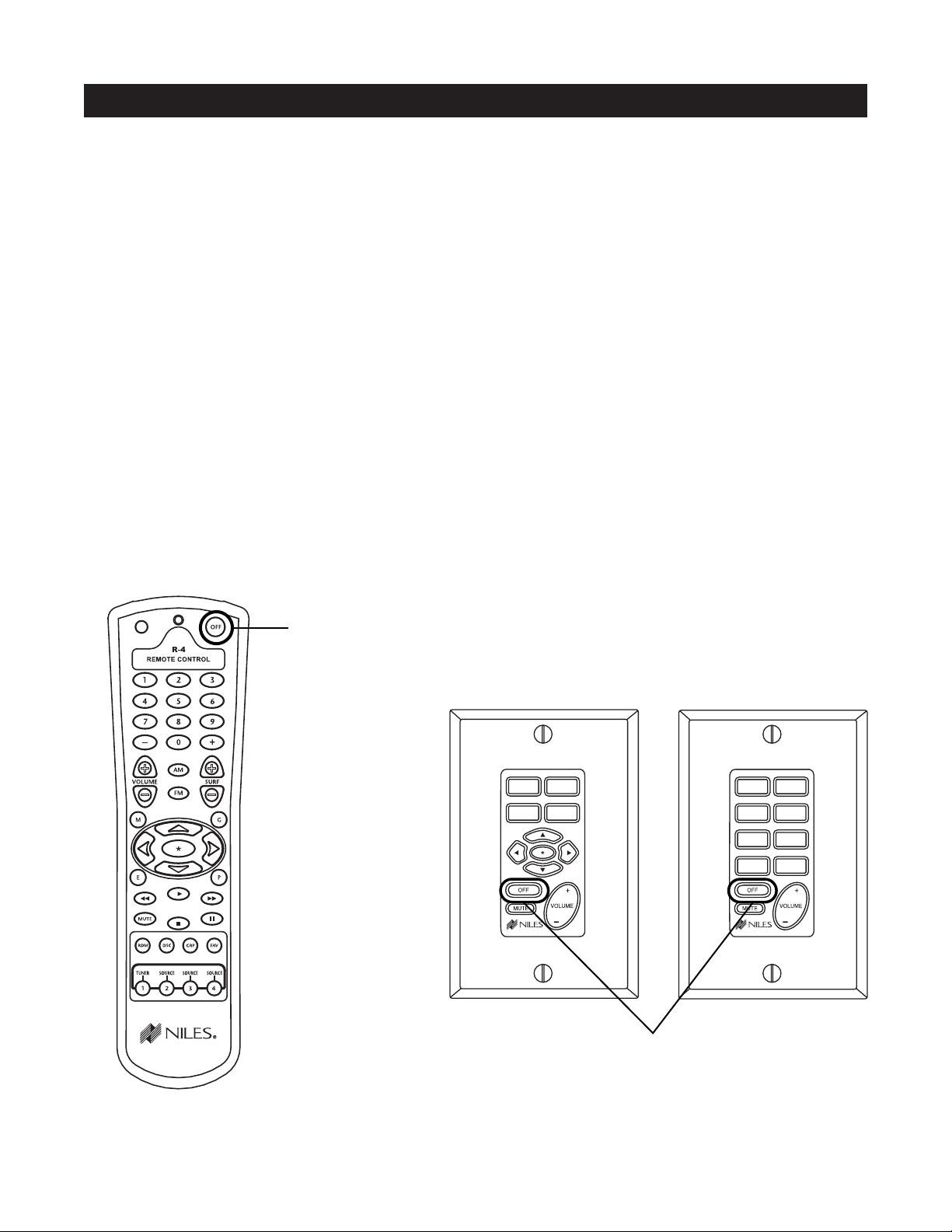
OFF KEY/OFF BUTTON
The OFF Key/Button included on the Solo
™
and Select™Master Keypad Module and the R-4 Remote provide
one-touch system deactivation. When you finish listening in a zone, a single press of the OFF Key/Button deactivates the zone.
OPERATIONAL OVERVIEW
Off Button on the
Hand-Held R-4
Remote Accessory
Off Key on the Solo
™
Master Keypad Module
Figure 23
DVD
JAZZ ROCK
BLUES
POP
TUNER
CD
DSS
TUNER
DVD
CD DSS
Page 31

OFF KEY EVENTS
When you press the OFF Key/Button, up to four events may occur. The first event is the Zone OFF sequence
programmed by the installer for the zone that is turning OFF.
The second event is factory programmed and turns the zone or all zones OFF every time the OFF Key/Button
is pressed.
The third event is responsible for turning OFF the source components and occurs only if the zone turning OFF
was the last zone ON in the system (including the Home Theater zone that shares source components). This
event requires no programming. The programming accomplished for the Master Key Source ON events is
reversed to deactivate the source components.
The fourth event is the System OFF sequence programmed by the installer. It occurs only if the zone turning
OFF was the last zone ON in the system (including the Home Theater Zone that shares source components).
OFF KEY/BUTTON OPERATION
The manner in which the Off Key/Button operates the system is determined by the system configuration and
how the OFF Key/Button is pressed.
These various types of operation are especially useful in systems with multiple rooms within the zones.
Important Note: When a zone has more than one room, a Niles Silencer Volume Control and Master Keypad
Module are required in each room within the zone to provide individual ON/OFF and volume adjustment.
Following is an operational description for zones with one room and zones expanded into multiple rooms
using Silencers.
A Zone with One Room
Individual-Room Operation - A press of the Off Key for less than three seconds in a zone that is currently
ON (selected Master Key illuminated GREEN) causes that zone to turn OFF (Master Key LED turns OFF).
OFF Key Events 1 and 2 occur for that zone. OFF Key Events 3 and 4 occur if that zone is the last zone turning OFF in the System and the Home Theater that shares sources is also OFF.
System-Wide Operation - A press and hold of the OFF Key for more than three seconds always turns all
zones OFF (Master Key LEDs turn OFF). Event 1 occurs in the zone issuing the All OFF command and Event
2 occurs for all other zones, sequentially. Additionally, Events 3 and 4 occur if the Home Theater that shares
sources is also OFF.
OPERATIONAL OVERVIEW
31
Event 1 Event 2 Event 3 Event 4
Zone-OFF
Sequence
Zone OFF Source Power OFF
System-OFF
Sequence
Installer
Programmed
Programmed
Automatically
Factory
Programmed
Installer
Programmed
Page 32

32
OPERATIONAL OVERVIEW
Multiple Rooms in a Zone Using an Expander and Silencers
Individual-Room Operation - Multiple rooms within a zone using silencers require two short taps of the
OFF Key to turn OFF that zone individually.
A press of the OFF Key for less than three seconds in a room that is currently ON (selected Master Key illuminated GREEN) causes that room to MUTE (selected Master Key now illuminates RED).
A press of the OFF Key for less than three seconds in a room that is ON and MUTED (selected Master Key
illuminated RED), causes the entire zone to turn OFF (all Master Key LEDs turn OFF). OFF Key Events 1 and
2 occur when the zone turns OFF. Additionally, Events 3 and 4 occur if the zone is the last zone in the system turning OFF and the Home Theater that shares sources is also OFF.
System-Wide Operation - A press and hold of the OFF Key always turns all zones off (Master Key LEDs turn
OFF). Event 1 occurs in the zone issuing the All OFF command and Event 2 occurs for all other zones,
sequentially. Additionally, Events 3 and 4 occur if the Home Theater that shares sources is also OFF.
VOLUME KEYS/VOLUME BUTTONS
The volume keys on the Solo
™
and Select™Master Keypad Module and the volume buttons on the R-4 Remote
provide control of volume for individual zones.
VOLUME KEYS/VOLUME BUTTONS OPERATION
Pressing the Volume + or the Volume – Keys/Buttons raises and lowers the preamplifier output for the zone in
which you are located.
Important Note: Zones with multiple rooms including Silencer Muting Volume Controls have the Volume Keys
on the Master Keypad replaced with the included Surf+/Surf– Function Keys/Buttons (refer to the Silencer
Operation and Installation Guide for more details). IR commands programmed into the Surf+/Surf– Function
Keys/Buttons are issued from these keys when using a Master Keypad installed with a Silencer (see page 56 for
details on programming Function Keys).
Volume Buttons on
the R-4 Hand-Held
Remote Accessory
Figure 24
Volume Keys on the Solo™and
Select
™
Master Keypad Module
DVD
JAZZ ROCK
BLUES
POP
TUNER
CD
DSS
TUNER
DVD
CD DSS
Page 33

MUTE KEY/MUTE BUTTON
The Mute Key/Button provides a method of turning the sound ON\OFF for a brief moment in an individual
zone without turning the zone OFF. (This also prevents the source components from being turned OFF.)
MUTE KEY/MUTE BUTTON OPERATION
In a single-room zone, the Mute Key mutes and unmutes the preamplifier for that zone only. The system still
considers the zone to be ON while the zone is MUTED. The Master Key lights GREEN while the zone is ON,
and RED while the zone is MUTED. If a zone has more than one Master Keypad Module, but has no silencers,
all the Master Keypad modules always illuminate identically.
In a zone including many rooms with silencers, the Mute Key mutes and unmutes the silencer for that room
only. The system considers the room to be ON while the zone is muted. The Master Key lights GREEN while
the room is ON, and RED while the room is MUTED. A muted room also will un-mute if any Master Key is
pressed or if the volume keys are pressed.
33
OPERATIONAL OVERVIEW
Mute Button on
the R-4 Hand-Held
Remote Accessory
Figure 25
Mute Key on the Solo™and
Select™Master Keypad Module
DVD
JAZZ ROCK
BLUES
POP
TUNER
CD
DSS
TUNER
DVD
CD DSS
Page 34

FUNCTION KEYS/BUTTONS
The Solo
™
Master Keypad Module, the Transport™Accessory Keypad Module and the R-4 Remote include various function keys for control of the connected source components. Figure 23 illustrates the available function
keys for all of the control devices.
FUNCTION KEY/BUTTON OPERATION
After the Master Key/Source Button for a connected source component has been pressed, the A4.6Ci activates
a zone and selects that source component. The individual Function Keys/Buttons in that zone will now issue
the IR commands that have been programmed for the selected source component. A sequence of IR commands
and/or delays can be issued when a Function Key/Button is programmed with a Function Key/Button Sequence.
34
OPERATIONAL OVERVIEW
Function Keys on the Solo™ Master Keypad
Module, the Transport™Accessory Module
and the Hand-Held R-4 Remote Accessory
Figure 25
Page 35

Important Note: Operation of identical source components is not possible using the source components’ actual
IR commands in a zone installed with an IR sensor. (i.e., using the source component’s original remote control or
a learning remote control programmed with these IR commands). Identical source components can be operated
from a zone with an IR sensor using Niles IR commands from the preamplifier or from the hand-held R-4 Remote
commands (see Programming Overview for more information).
SHARED SOURCE COMPONENTS
Source components (i.e. DVD player, CD changer, DSS receiver) used with an A4.6Ci, can be “shared” with
multiple A4.6Ci’s and/or a Home Theater system (refer to System Configurations 2, 3, and 4 for more details).
The A4.6Ci has been designed to provide coordinated control of these shared source components from all
zones of all A4.6Ci’s and the Home Theater.
A source component in an A4.6Ci multi-zone system is considered “shared” when its audio signal is connected to more than one A4.6Ci or if it is connected to an A4.6Ci and a Home Theater system (refer to System
Configuration 2 and System Configuration 3 for more details).
OPERATING A SYSTEM WITH MULTIPLE A4.6Ci’s
Operating a system with multiple A4.6Ci’s is the same as operating a system with only one A4.6Ci Solo
™
or Select
™
Master Keypad. Modules in each zone independently operate the zone to which they are dedicated (i.e., Zone
ON/OFF, Volume Up/Down, Mute). When a user in a zone from any A4.6Ci, presses a key/button, the IR commands
required for the shared source components (i.e., Power ON/OFF, Play, Stop and Channel Up), are issued by the
A4.6Ci that has been programmed. (See the Programming Section of this manual for specific details on programming.)
35
OPERATIONAL OVERVIEW
Assigned Source Flasher 1 Flasher 2 Flasher 3 Flasher 4
Source 1
X
Source 2
X
Source 3
X
IDENTICAL SOURCE COMPONENTS
The A4.6Ci routes the individual source-component IR commands that with which it has been programmed to
specific flasher outputs. This provides individual control of identical source components (i.e., two DSS receivers
of the same brand and model). These programmed IR commands are routed to the individual flasher outputs
based on the assigned source for which they were programmed. The table below designates where IR commands are routed when a zone is selected to one of the three source components.
FLASHER OUTPUTS
Source 4
X
Page 36

OPERATING A SYSTEM INTEGRATED WITH A HOME THEATER
Operation from the Stereo Zones Provided by the A4.6Ci
User operation from the zones provided by A4.6Ci’s, are not affected when integrating a Home Theater to
share source components (see System Configurations 3 and 4). Solo™ or Select™ Master Keypad Modules in
each zone independently operate the zone to which they are dedicated (i.e., Zone ON/OFF, Volume
Up/Down, Mute). When a user in a zone from any A4.6Ci, presses a key/button, the IR commands required
for the shared source components (i.e., Power ON/OFF, Play, Stop and Channel Up) are issued by the A4.6Ci
that has been programmed. (See the Programming Section of this manual for specific details on programming.)
Operation from the Home Theater Zone
A Home Theater can be integrated to share source components with an A4.6Ci using one of three methods.
How the Home Theater will operate depends on which method is chosen. The three methods of integration are listed below, along with a description of the Home Theater operation they provide.
Method 1. Integrated Home Theater Using 12V Home Theater Sync and IR Repeating
The Home Theater IR Remote (programmed with the actual IR commands of the shared source components) sends IR commands to the shared source components via the IR Input located on the rear panel
of the A4.6Ci. This enables control of the shared source components for users in the Home Theater. All
IR commands for shared source components are passed through to all four of the flasher outputs on the
rear panel of the A4.6Ci. Only discrete power ON and transport commands for the shared source components should be issued.
Important Note: Because all of the actual IR commands for shared components are passed through to
all the flasher outputs simultaneously, identical source components cannot operate individually with this
method. Also, when using this method, reliable activation of shared source components that use a single IR command for power ON/OFF is not possible. (Refer to Method 2 for operating identical shared
source components and components with a single IR command for power ON/OFF.)
When the Home Theater turns ON, it provides a 12V status signal that is connected to the Home Theater sync
input on the rear panel of the A4.6Ci. This provides the ON/OFF status of the Home Theater to the A4.6Ci.
The moment a valid Home Theater sync signal is present at the A4.6Ci, the A4.6Ci’s 12V control output sends a turn-on trigger for a voltage-triggered AC power strip (i.e., Niles AC-3) to activate latching
source components.
When the Home Theater is turned OFF, the A4.6Ci checks itself and any other A4.6Ci’s in the system to
see if any zones are still ON. If all zones are OFF, the 12V control output shuts OFF, turning OFF the
latching source components. Power OFF IR commands for turning OFF the IR-controlled shared source
components also are issued.
Method 2. Integrated Home Theater Using 12V Home Theater Sync and Niles R-4 Commands
The Home Theater IR remote (programmed with the Niles R-4 IR commands) sends IR commands to the
A4.6Ci via the IR input on the rear panel. This enables control of the shared source components for users
in the Home Theater.
All the actual IR commands for shared source components are programmed into the A4.6Ci. When a
Niles IR command is received, the corresponding programmed source IR commands are sent to the
flasher output dedicated to the shared source component that is selected (i.e., Source 1 = Flasher 1,
Source 2 = Flasher 2, Source 3 = Flasher 3, Source 4 = Flasher 4). Identical source components can be
individually operated with this method.
Important Note: Shared source components that are unique in the system can have their actual IR commands programmed into the Home Theater remote and issued for simple IR repeating with this method.
36
OPERATIONAL OVERVIEW
Page 37

When the Home Theater turns ON, it provides a 12V status signal that is connected to the Home Theater
sync input on the rear panel of the A4.6Ci. This 12V status signal provides the ON/OFF status of the
Home Theater to the A4.6Ci.
The moment a valid Home Theater sync signal is present at the A4.6Ci, the A4.6Ci’s 12V control output sends a turn-on trigger for a voltage-triggered AC power strip (i.e., Niles AC-3), activating latching
source components.
When the Home Theater is turned OFF, the A4.6Ci checks itself and any other A4.6Ci’s in the system to
see if any zones are still ON. If all zones are OFF, the 12V control output shuts OFF, turning OFF the
latching source components. Power OFF IR commands for turning OFF the IR-controlled shared source
components also are issued.
Method 3. Integrated Home Theater without 12V Home Theater Sync and Using Niles R-4 Commands
The Home Theater IR remote (programmed with the Niles R-4 IR commands) sends IR commands to the
A4.6Ci via the IR input located on the rear panel. This enables control of the shared source components
for users in the Home Theater.
All the actual IR commands for shared source components are programmed into the A4.6Ci. When a
Niles IR command is received, the corresponding programmed source IR commands are sent to the
flasher output dedicated to the shared source component that is selected (i.e., Source 1 = Flasher 1,
Source 2 = Flasher 2, Source 3 = Flasher 3, Source 4 = Flasher 4). Identical source components can be
individually operated with this method.
Important Note: Shared source components that are unique in the system may have their actual IR commands programmed into the Home Theater remote and issued for simple IR repeating using this method.
When the Home Theater is turned OFF, the Home Theater remote sends a Niles OFF command to the
A4.6Ci. The A4.6Ci then checks all zones, for all A4.6Ci’s in the system. If all zones are OFF, the 12V
control output shuts OFF, turning OFF the latching source components. Power OFF IR commands for
the IR-controlled shared source components programmed into the A4.6Ci also are issued, conditionally, based on the source-sync status of the shared source components.
SYSTEM-BUSY INDICATION
The A4.6Ci has a built-in system-busy indication mode that is displayed on the Master Key LEDs of the Solo
™
Master Keypad Module. If the A4.6Ci receives simultaneous commands from two different users and each user
is located in a separate zone, the user who does not get the expected response will be alerted by the Master
Key. That Master Key LED will quickly blink RED three times. The user who received the RED flashing Master
Key simply issues his or her command again.
Important Note: IR commands and delays included in the sequence for Master Keys also cause the system to indicate busy while they are being executed.
PAGING INDICATION
The A4.6Ci has a built-in paging-indication mode that is displayed on a Master Key LED of the Solo
™
or Select™Master
Keypad Module. If the A4.6Ci sends a page to a zone, the user is alerted by the Master Key. That Master Key LED will
blink slowly GREEN. The Master Key LED resumes its last state (ON or OFF) when the page is completed.
Important Note: Paging takes priority over all system functions until the page has ended.
37
OPERATIONAL OVERVIEW
Page 38

PLACEMENT
Place the A4.6Ci on a flat, level surface such as a table or shelf, with its weight equally distributed on each of its
four feet. Like any high-fidelity component, the A4.6Ci will last much longer if it receives adequate ventilation for
proper cooling (see Figure 28).
38
OPERATIONAL OVERVIEW
Make sure that there is a minimum of 1” of
free air space above the preamplifier and 1”
on each side for proper ventilation.
Allow a minimum of 2” of depth behind unit to
accommodate cables and connectors.
Figure 28
Page 39

TERMINATING FOUR-PAIR TWISTED CABLE
The Solo
™
and Select™Master Keypad Modules, the expander, and the A4.6Ci’s system-expansion connections
require a four-pair twisted cable with a one-to-one wiring configuration. To maintain consistency throughout
all Intellipad
®
Ci installations, we recommend the color-coding pattern described in Figure 31. However, you
may follow the color-coding pattern of your choice, as long as it is consistent throughout the system.
39
CONNECTIONS
1 = Green/White
2 = Green
3 = Orange/White
4 = Blue
5 = Blue/White
6 = Orange
7 = Brown/White
8 = Brown
Figure 31
Figure 32
Figure 33
CONNECTING
NUMERIC
™
KEYPADS
Each Solo
™
and Select™Master Keypad
Module can be mated with one
optional Numeric
™
Accessory Keypad
Module using an included jumper
cable (see Figure 33).
CONNECTING THE SOLO
™
AND SELECT™MASTER KEYPADS TO
THE HOME RUN OF FOUR-PAIR TWISTED CABLE
The home run of four-pair twisted cable is terminated with a male
RJ-45 connector and plugged into the rear-panel jack labeled SYSTEM on the Solo
™
and Select™Master Keypad Module (see Figure 32).
Pair 3 Pair 4
Pair 2
Pair 1
1234
567
8
T568A
RJ-45 Connector
for connection to
IR Sensors
RJ-45 Connector
for connection to
Numeric™ Accessory
Keypad Module
RJ-45 Connector for
connection to
the ZR-4630
INPUT
IR SENSOR
SYSTEM
ACCESSORY
KEYPADS
™
Solo
Master
Keypad Module
OUTPUT
Included
Jumper Cable
Numeric
Accessory
Keypad Module
RJ-45 Connector for
connection to Master
Keypad Module
™
Page 40

40
CONNECTIONS
CONNECTING IR SENSORS
An IR sensor can be connected to a Solo
™
and
Select
™
Master Keypad Module in one of two
ways, directly with a four-pair twisted cable
(see Figure 34 and 35), or with a three-wire to
RJ-45 adapter available from Niles for IR sensors installed with two-conductor shielded
cable. (See Figure 36 and the Accessories
Section of this manual.)
Connecting a Sensor Using Four-Pair
Twisted Cable
In Figure 34, one end of the four-pair twisted
cable connects with bare wire to the IR sensor.
The other end terminates with a male RJ-45
connector and plugs into the Solo
™
and
Select
™
Master Keypad Module.
Figure 34 depicts the correct wires to use for connection to the IR sensor when using four-pair twisted cable
terminated with an RJ-45 connecter at the Solo
™
and Select™ Master Keypad Module.
Figure 34
1
1= 1 2 V 3 = GND
2 = DATA
234
Pair 2
Pair 1
T568A
Pair 3 Pair 4
567
8
Figure 35
Figure 36
Connecting a Sensor Installed with Two-Conductor Shielded Cable
An IR sensor installed with two-conductor shielded cable requires the Niles three wire to RJ-45 adapter (see
Accessories) for proper connection to a Solo
™
and Select™Master Keypad Module (see Figure 36). The IR sensor connects to the two-conductor shielded cable with bare-wire, screwdown terminals. (Refer to the IR sensors Installation Guide for more information.) The two-conductor shielded cable then connects to the adapter’s
bare-wire, screwdown terminal, matching 12V, GND, and Data respectively.
Four Pair Twisted Cable
RJ-45 Connector for
connection to
the ZR-4630
RJ-45 Connector
for connection to
IR Sensors
RJ-45 Connector
for connection to
Numeric Accessory
Keypad Module
IR SENSOR SYSTEM
ACCESSORY
KEYPADS
Niles
IRR-4D+
IR Sensor
Keypad Module
™
Solo
Master
Two-Conductor
Shielded Cable
Three-Wire to
RJ-45 Adapter
RJ-45 Connector for
connection to
the ZR-4630
RJ-45 Connector
for connection to
IR Sensors
RJ-45 Connector
for connection to
Numeric Accessory
Keypad Module
Niles
IRR-4D+
IR Sensor
IR SENSOR SYSTEM
ACCESSORY
KEYPADS
™
Solo
Master
Keypad Module
Page 41

41
CONNECTIONS
SOURCE-COMPONENT AUDIO SIGNALS
1. Audio Output of Source Components to the A4.6Ci
Male-to-male RCA audio cables connect the four external audio sources.
2. Buffered-Cascade Audio Output of Source
Components to Slave A4.6Ci’s or a Home Theater
Male-to-male RCA audio cables connect Slave A4.6Ci’s or
the Home Theater.
TELEPHONE PAGING
3. Paging Output of Telephone System to A4.6Ci
Page Input
A male-to-male RCA audio cable connects the paging
output of a telephone system to the A4.6Ci.
SYSTEM EXPANSION
4. System Expansion Input to System Expansion Output
Four-pair twisted cable, terminated with male RJ-45
plugs, connects multiple A4.6Ci's using the System
Expansion Input and Output terminals. Connections are
made from the input of one of the A4.6Ci's to the output
of another, and so on. (For more information on
Terminating Four-Pair Twisted Cable, refer to page 39.)
SOURCE-COMPONENT POWER AND HOME THEATER
SYNCHRONIZATION SIGNALS
5. 12V Home Theater Sync to Home Theater Sync Input
The 12V Home Theater sync signal connects with a
mini-plug to the Home Theater sync input.
6. Video Synchronization from a Source Component
to an A4.6Ci Sync Input
An RCA Y-adapter is used to split the video output of a
source component for connection to one of the two
source sync inputs of the A4.6Ci (1 or 2). One side of the
RCA Y-adapter connects to the appropriate source sync
input and the other side connects to the intended destination for the video signal (i.e., the video input of a TV,
receiver, or RF modulator).
The need for an RCA Y-adapter can be avoided if your
video source has two video outputs. One video output
connects to a source sync input and the other to the
intended destination of the video signal.
Important Note: Source sync inputs are designed with
high-input impedances so as not to affect the quality of
the video signal when using an RCA Y-adapter.
1
2
3
4
5
6
Figure 37
1 2 3 4
109 11 12 13 14 15
75 6
8
Page 42

42
CONNECTIONS
HOME THEATER CONTROL SYSTEM
7. Voltage Sync from a Source Component to an
A4.6Ci Sync Input
When obtaining a 12V sync signal from a source component (refer to the Source Power Synchronization section of
this manual for more information), a Niles Accessory Cable
(FG00724) connected to a Radio Shack 274-326 mini-plug
to male RCA adapter provides proper connection to any of
the three source sync Inputs.
KEYPAD MODULES
8. Keypads to Keypad Inputs for Zones 1-6
Four-pair twisted cable, terminated with male RJ-45
plugs, connects the keypads to the zoned keypad inputs
(for more information on Terminating Four-Pair Twisted
Cable, refer to page 39).
PREAMPLIFIER ZONE OUTPUTS
1. Zones 1-6
Male to male RCA audio cables connect Zone Outputs
1-6 to an external amplifier.
1. Zones 1-6
DB-25 Audio Cables (1-to-1 pin configuration) connect
Zone Outputs 1-6 to a Niles multi-channel amplifier.
HOME THEATER CONTROL SYSTEM
1. IR Output of a Home Theater Control System to the IR In
The mini-plug end of a Niles Accessory Cable
(FG00724) connects a Home Theater control system to
the IR input.
12V CONTROL SIGNALS
1. 12V Control Output to a Voltage Triggered Device
The mini plug end of a Niles Accessory Cable (FG00724)
connects the 12V control output to the trigger input of a
voltage-activated device (i.e., Niles AC-3).
IR FLASHERS
1. Low-Output Flasher to the Flasher Outputs
The mini-plug end of a Niles Low-Output MicroFlasher,
™
Model IRC-2P (FG00726), connects into the Flasher
Outputs 1-4. The Micro-Flasher portion of the IRC-2P is
placed directly over the IR sensor of the corresponding
source component (Source 1 for Flasher 1, Source 2 for
Flasher 2, Source 3 for Flasher 3, Source 4 for Flasher 4)
and adheres with the included peel-back tape.
1. High Output Flasher to the Flasher Outputs
The mini plug end of a Niles High-Output Flasher, Model
IRC-1P (FG00932), connects to the Flasher Output 4
labeled ADJUST. The IRC-1P is strategically positioned to
provide IR transmission to all source components and
adheres with its included Velcro mounting system.
DC POWER
1. DC Power Adapter
The 16V DC power adapter (included with the A4.6Ci)
connects to the removable power-cord socket and to an
AC power outlet.
8
9
10
11
12
131415
7
Page 43

43
CONNECTIONS
CONNECTING AN IR SENSOR FOR LOCAL SYSTEM CONTROL
IR Sensors installed in zones for hand-held IR remote control of the A4.6Ci and its connected source components can also be used to control local components (i.e., a TV, DSS, DVD, and a surround-sound system located in the master bedroom zone as shown in Figure 38).
The IR sensor connects normally to the Solo
™
and Select™Master Keypad to control the A4.6Ci and its connected source components. In addition, the IR sensor connects to a local IR repeating system (DATA and GND
connections only) to provide control of local components.
TV
Four-Pair Twisted Cable
LR
AUDIO VIDEO
DSS
PHONE
DIGITAL
LR
AUDIO VIDEO
DVD
RECEIVER
DIGITAL
LR
AUDIO
CD
DVD
Video 3
Video 2
Video 1
VIDEO
FRONT
L
L
R
DIGITAL
1
2
R
CENTER
REAR
L
R
12V
D.C.
Niles IRP-6+
(provided for IR control
of local equipment)
Zone 6 – Master Bedroom
Distributed Equipment Location
Plugged into
Switched AC outlet
Niles
IRR-4D+
IR Sensor
Solo
Master
Keypad Module
RJ-45 Connector
for connection to
Numeric Accessory
Keypad Module
RJ-45 Connector
for connection to
Master Keypad
Module
RJ-45 Connector
for connection to
IR Sensors
Two-Conductor Shielded Cable
(connect DATA and GND only)
Two-Conductor
Shielded Cable
Three-Wire to
RJ-45 Adapter
RJ-45 Connector for
connection to
the A4.6Ci
Included
Jumper Cable
IR SENSOR
INPUT
OUTPUT
SYSTEM
ACCESSORY
KEYPADS
Figure 38
Page 44

44
CONNECTIONS
CONNECTING AN A/B AMPLIFIER SWITCH FOR LOCAL SYSTEM SELECTION
A Niles SPK-1 Voltage-Activated Speaker Level A/B Switcher connects to both the A4.6Ci and a local system
to provide sound from each system to the same speakers located in a single zone. The local system only connects to the speakers when the local system is turned on. The Niles A4.6Ci connects to the speakers by default
when the local system is off.
As shown in Figure 39, the zoned speaker output of the A4.6Ci connects to the "A" side of the SPK-1. The main
speaker output of the local system connects to the "B" side of the SPK-1. In addition, a 12V DC power adapter
(Niles FG00665) is plugged into a switched AC outlet of the local system to activate the SPK-1.
Zone 6 – Master Bedroom
Distributed Equipment Location
I
N
F
R
A
R
E
D
S
E
N
S
O
R
K
N
O
C
K
O
U
T
I
N
F
R
A
R
E
D
S
E
N
S
O
R
K
N
O
C
K
O
U
T
I
N
F
R
A
R
E
D
S
E
N
S
O
R
K
N
O
C
K
O
U
T
I
N
F
R
A
R
E
D
S
E
N
S
O
R
K
N
O
C
K
O
U
T
I
N
F
R
A
R
E
D
S
E
N
S
O
R
K
N
O
C
K
O
U
T
LR
AUDIO
CD
DVD
DSS
Video 1
Video 2
VIDEO
FRONT
L
L
R
DIGITAL
1
2
R
CENTER
REAR
L
R
12V
D.C.
Rear
Speakers
Center
Left
Front
Right
Front
Niles SPK-1
Plugged into
Switched AC outlet
Figure 39
Page 45

PROGRAMMING PANEL
IR commands needed for control of connected external source components are programmed into the A4.6Ci’s
program memory using the hidden programming controls on the front panel (see Figure 42).
Programming is accomplished by using the hidden panel’s push buttons and LED prompts, and by sending
commands from connected Niles Master Keypad and Accessory Keypad Modules, and IR commands from the
remotes supplied with the source components (see Figure 41). A Niles hand-held R-4 Remote can be used
instead of a connected Master Keypad Module (see Figure 42). For complete information on the A4.6Ci’s stepby-step programming procedure, refer to the Programming Steps section of this manual.
45
PROGRAMMING OVERVIEW
Figure 42
Niles hand-held
R-4 Remote Control
(sold separately)
Source Components
IR Remote Control
(supplied by manufacturer)
Hidden Installer
Programming Panel
Figure 41
Source Components
IR Remote Control
(sold separately)
Hidden Installer
Programming
Panel
Select™
or Solo™
Transport™Numeric™
Note: R-4 does not include Master Keys 5-8.
Page 46

INSTALLATION AND PROGRAMMING DOCUMENTATION
Why Document?
There are three important reasons why you should keep thorough documentation of the installation and the
programming procedure:
• It enables you to program the system properly. When using multiple preamplifiers or programming
sequences, knowing where individual IR commands are programmed is critical. Precise documentation
minimizes delays due to poor planning, and avoids duplication of effort.
• It creates a detailed record that will be invaluable for future upgrades and troubleshooting.
• It enables Niles Technical Support to assist you more efficiently.
Documentation Overview
This section covers the various fill-in schematics and worksheets available to document quickly the basic architectural and programming information regarding the system you are installing. For specific information on actual
connections and how to configure the system, see System Configurations.
The system documentation was designed to minimize your time investment, while still providing all the necessary information that will be required to design, install, and troubleshoot an A4.6Ci preamplifier. As you complete the various forms, you will find that the information is simply the normal questions you are required to ask
when designing a typical distributed audio system.
The documentation sheets provided with this manual are divided into two categories: schematics and worksheets.
• Schematics keep a record of your system's architecture (Figures 43 and 44).
46
PROGRAMMING OVERVIEW
Master Preamplifier Schematic
Slave Preamplifier Schematic
Figure 43
Preamplifier Schematics
JOB TITLE
1
ZONE SETUP
12
MASTERKEYPAD MODULE
(CHOOSEONE)
❏SOLO ❏ SELECT
❏INPUT EXPANDER
OPTIONALACCESSORY
MODULES
❏NUMERIC
❏TRANSPORT
❏IR SENSOR
ZONE#
ZONE NAME
FROM EXPANDER #
MASTER PREAMPLIFIER INSTALLATION SCHEMATIC
AUDIO INPUTS
3
SOURCE
BRAND/MODEL
SOURCE
1
2
3
4
PAGING DEVICE
5
❏ YES ❏ NO
6
Ci Net™CONNECTIONS
FROM
TO
CASCADE OUTPUT
10
SOURCE
❏ YES ❏NO
SOURCE
DESTINATION
1
2
3
4
MASTERKEYPAD MODULE
(CHOOSEONE)
❏SOLO ❏ SELECT
❏INPUT EXPANDER
OPTIONALACCESSORY
MODULES
❏NUMERIC
❏TRANSPORT
❏IR SENSOR
1
ZONE#
2
ZONE NAME
FROM EXPANDER # FROM EXPANDER # FROM EXPANDER # FROM EXPANDER # FROM EXPANDER #
FLASHER
A
B
C
D
MASTERKEYPAD MODULE
(CHOOSEONE)
❏SOLO ❏ SELECT
❏INPUT EXPANDER
OPTIONALACCESSORY
MODULES
❏NUMERIC
❏TRANSPORT
❏IR SENSOR
ZONE#
3
ZONE NAME
SYSTEM DESIGNER
2
HOME THEATER SYNC
7
❏ YES ❏ NO
HOME THEATER IR
❏ YES ❏ NO
VOLTAGEACTIVATED DEVICE
8
❏ YES ❏ NO
ZONE OUTPUT
11
SOURCE
❏ RCA ❏ DB-25
ZONE
1
2
3
4
5
6
MASTERKEYPAD MODULE
(CHOOSEONE)
❏SOLO ❏ SELECT
❏INPUT EXPANDER
OPTIONALACCESSORY
MODULES
❏NUMERIC
❏TRANSPORT
❏IR SENSOR
ZONE#
ZONE NAME
SYNC INPUTS
4
SOURCE
SYNC2TYPE
SOURCE
❏ YES ❏NO
1
❏ YES ❏NO
MASTER A4.6Ci
9
ZONE
1
2
3
4
5
6
A
B
C D
SETTING
AMPLIFIER
FIXED/VARIABLE
/
❏❏
❏❏
/
❏❏
/
❏❏
/
❏❏
/
/
❏❏
MASTERKEYPAD MODULE
(CHOOSEONE)
❏SOLO ❏ SELECT
❏INPUT EXPANDER
OPTIONALACCESSORY
MODULES
❏NUMERIC
❏TRANSPORT
❏IR SENSOR
ZONE#
4
5
ZONE NAME
❏ VIDEO ❏ 12V
❏ VIDEO ❏ 12V
ALL ON / PAGE
❏
❏
❏
❏
❏
❏
MASTERKEYPAD MODULE
(CHOOSEONE)
❏SOLO ❏ SELECT
❏INPUT EXPANDER
OPTIONALACCESSORY
MODULES
❏NUMERIC
❏TRANSPORT
❏IR SENSOR
ZONE#
6
ZONE NAME
JOB TITLE
1
3
PREAMPLIFIER (CHOOSE ONE)
❏ (1) SLAVE - ZONE 7-12 ❏ (2) SLAVE - ZONE 13-18
4
AUDIO INPUTS
SOURCE
SOURCE
1
2
3
4
ZONE SETUP
10
MASTERKEYPAD MODULE
CHOOSEONE)
(
❏SOLO ❏ SELECT
❏INPUT EXPANDER
OPTIONALACCESSORY
❏NUMERIC
❏TRANSPORT
❏IR SENSOR
1
ZONE#
ZONE NAME
FROM EXPANDER #
SLAVE PREAMPLIFIER INSTALLATION SCHEMATIC
SYSTEM DESIGNER
2
❏ (3) SLAVE - ZONE 19-24
5
PAGINGDEVICE
FROM
❏ YES ❏NO
6
Ci Net™Connections
TO
FROM
ZONE OUTPUT
MASTERKEYPAD MODULE
(CHOOSEONE)
❏SOLO ❏ SELECT
❏INPUT EXPANDER
OPTIONALACCESSORY
MODULES
❏NUMERIC
❏TRANSPORT
❏IR SENSOR
ZONE NAME
9
SOURCE
❏ RCA ❏ DB-25
ZONE
1
2
3
4
5
6
MASTERKEYPAD MODULE
(CHOOSEONE)
❏SOLO ❏ SELECT
❏INPUT EXPANDER
OPTIONALACCESSORY
❏NUMERIC
❏TRANSPORT
❏IR SENSOR
ZONE NAME
CASCADE OUTPUT
8
SOURCE
❏ YES ❏NO
SOURCE
DESTINATION
1
2
3
4
MASTERKEYPAD MODULE
(CHOOSEONE)
❏SOLO ❏ SELECT
❏INPUT EXPANDER
OPTIONALACCESSORY
MODULES
MODULES
❏NUMERIC
❏TRANSPORT
❏IR SENSOR
ZONE#2ZONE#3ZONE#4ZONE#5ZONE#
ZONE NAME
FROM EXPANDER # FROM EXPANDER # FROM EXPANDER # FROM EXPANDER # FROM EXPANDER #
7
SLAVE A4.6Ci
ALL ON / PAGE
ZONE
1
_________
2
_________
3
_________
4
_________
5
_________
6
_________
SETTING
AMPLIFIER
FIXED/VARIABLE
/
❏❏
❏❏
/
❏❏
/
❏❏
/
❏❏
/
/
❏❏
MASTERKEYPAD MODULE
MASTERKEYPAD MODULE
(CHOOSEONE)
(CHOOSEONE)
❏SOLO ❏ SELECT
❏SOLO ❏ SELECT
❏INPUT EXPANDER
❏INPUT EXPANDER
OPTIONALACCESSORY
❏NUMERIC
❏TRANSPORT
❏IR SENSOR
ZONE NAME
OPTIONALACCESSORY
MODULES
❏NUMERIC
❏TRANSPORT
❏IR SENSOR
6
ZONE NAME
MODULES
❏
❏
❏
❏
❏
❏
MODULES
Page 47

Each A4.6Ci has six zones to document. Fill out one Master Preamplifier Schematic for the Master A4.6Ci, and
one Slave Preamplifier Schematic for each Slave A4.6Ci in the system. Doing so determines how many zones
will be installed, the name of the room in a zone, and what keypads each room contains.
If you need expanders (required for multi-room and multi-area zones), use the Expander Schematics to keep a
record of all the rooms in the system and their corresponding keypads.
Complete one Multi-Area Schematic per expanded zone that doesn't have individual volume or on/off control
between areas.
Complete one Multi-Room Schematic per expanded zone in which silencers have been installed in all the rooms
for individual on/off and volume control.
• Worksheets are for documenting your programming (Figures 45–50).
47
PROGRAMMING OVERVIEW
123 45
PAGES
KEYS
▼
▼
PAGES
KEYS
▼
▼
Default Library
FUNCTION KEYS
1
2
3
4
5
6
7
8
9
0
-
+
RANDOM
GROUP
DISC
FAV
PLAY
STOP
PAUSE
REW
FF
M
G
E
P
UP
RIGHT
*
AM
FM
SURF +
SURF -
DOWN
LEFT
1
2
3
4
5
6
7
8
9
0
-
+
RANDOM
GROUP
DISC
FAV
PLAY
STOP
PAUSE
REW
FF
M
G
E
P
UP
RIGHT
*
AM
FM
SURF +
SURF -
DOWN
LEFT
678
PROGRAMMING WORKSHEET #2
FUNCTION KEY IR
MASTER A4.6Ci
1
JOB TITLE
2
SYSTEM DESIGNER
Function-Key IR Programming (Master A4.6Ci)
Figure 46 – Worksheet #2
Source IR/Power Programming
and Master-Key Setup
Figure 45 – Worksheet #1
1
2
3
OUTPUT
POWER
INPUTS
1
2
3
OUTPUT
POWER
INPUTS
1
2
3
OUTPUT
POWER
INPUTS
1
2
3
OUTPUT
POWER
INPUTS
Multi-Area Zone Schematic Multi-Room Zone Schematic
Figure 44
Expander Schematics
INTELLIPAD CiEXPANDER INSTALLATION SCHEMATIC
AREA 1
AREA NAME
AREA 2
AREA NAME
AREA 3
AREA NAME
❏SELECT
❏TRANSPORT
❏TRANSPORT
❏SELECT
❏TRANSPORT
MULTI-AREA ZONE
3
TO A4.6Ci
OUTPUT CONNECTION
JOB TITLE
1
Note: No individual volume or on/off control between areas
AREA SETUP
4
MASTERKEYPAD MODULE (CHOOSE ONE)
❏SOLO
OPTIONALACCESSORY MODULES
❏NUMERIC
❏IR SENSOR
MASTERKEYPAD MODULE (CHOOSE ONE)
❏SOLO ❏ SELECT
OPTIONALACCESSORY MODULES
❏NUMERIC
❏IR SENSOR
MASTERKEYPAD MODULE (CHOOSE ONE)
❏SOLO
OPTIONALACCESSORY MODULES
❏NUMERIC
❏IR SENSOR
SYSTEM DESIGNER
2
ZONE#
AREA 4
MASTERKEYPAD MODULE (CHOOSE ONE)
❏SOLO
❏SELECT
OPTIONALACCESSORY MODULES
❏NUMERIC
❏TRANSPORT
❏IR SENSOR
EXPANDER #
EXPANDER #
AREA NAME
AREA 5
MASTERKEYPAD MODULE (CHOOSE ONE)
❏SOLO ❏ SELECT
OPTIONALACCESSORY MODULES
❏NUMERIC
❏TRANSPORT
❏IR SENSOR
AREA NAME
Important Notes:
When using more than three Master Keypad
Modules in a zone, the second expander
connects to the first.
Important Notes:
When using more than three Master Keypad
Modules in a zone, keypads #3, #4 and #5
connect to a second expander.
JOB TITLE
1
Note: Individual volume and ON/OFF control provided by Silencer Volume Crontrols installed in each room
ROOM SETUP
4
MASTERKEYPAD MODULE (CHOOSE ONE)
❏SOLO ❏ SELECT
OPTIONALACCESSORY MODULES
❏NUMERIC
X
MASTERKEYPAD MODULE (CHOOSE ONE)
❏SOLO ❏ SELECT
OPTIONALACCESSORY MODULES
❏NUMERIC
X
MASTERKEYPAD MODULE (CHOOSE ONE)
❏SOLO ❏ SELECT
OPTIONALACCESSORY MODULES
❏NUMERIC
X
INTELLIPAD CiEXPANDER INSTALLATION SCHEMATIC
MULTI-ROOM ZONE
3
ROOM 1
❏TRANSPORT
❏IR SENSOR❏SILENCER
ROOM NAME
ROOM 2
❏TRANSPORT
❏IR SENSOR❏SILENCER
ROOM NAME
ROOM 3
❏TRANSPORT
❏IR SENSOR❏SILENCER
ROOM NAME
OUTPUT CONNECTION
TO A4.6Ci
ZONE#
EXPANDER #
EXPANDER #
SYSTEM DESIGNER
2
ROOM 4
MASTERKEYPAD MODULE (CHOOSE ONE)
❏SOLO ❏ SELECT
OPTIONALACCESSORY MODULES
❏NUMERIC
❏TRANSPORT
X
❏IR SENSOR❏SILENCER
ROOM NAME
ROOM 5
MASTERKEYPAD MODULE (CHOOSE ONE)
❏SOLO
❏SELECT
OPTIONALACCESSORY MODULES
❏NUMERIC
❏TRANSPORT
X
❏IR SENSOR❏SILENCER
ROOM NAME
Important Notes:
When using more than three Master Keypad
Modules in a zone, the second expander
connects to the first.
Important Notes:
When using more than three Master Keypad
Modules in a zone, keypads #3, #4 and #5
connect to a second expander.
PROGRAMMING WORKSHEET #1
JOB TITLE
1
PROGRAM SOURCE COMPONENT POWER – MASTER A4.6Ci
3
SOURCE 1 BRAND: _____________________________ MODEL: _____________________________
COMPONENT SYNC
❏ Yes ❏ No
SOURCE 2 BRAND:_____________________________ MODEL: _____________________________
COMPONENT SYNC
❏ Yes ❏ No
SOURCE 3 BRAND: _____________________________ MODEL: _____________________________
POWER PROGRAMMING
❏ Two Separate ON and OFF IR Commands ❏Latching Power
SOURCE 4 BRAND:_____________________________ MODEL: _____________________________
POWER PROGRAMMING
❏ Two Separate ON and OFF IR Commands ❏Latching Power
LABEL AND ASSIGN INPUTS TO MASTER KEYS – ALL MASTER & SLAVE A4.6Ci’s
4
MASTER KEY 1 MASTER KEY LABEL: ________
ASSIGNED SOURCE INPUT:
MASTER KEY 3 MASTER KEY LABEL: ________
ASSIGNED SOURCE INPUT:
MASTER KEY 5 MASTER KEY LABEL: ________
ASSIGNED SOURCE INPUT:
MASTER KEY 7 MASTER KEY LABEL: ________
ASSIGNED SOURCE INPUT:
SOURCE POWER IR AND MASTER KEY SETUP
If Yes, SYNC TYPE:
❏ Video ❏ 12V
If Yes, SYNC TYPE:
❏ Video ❏ 12V
❏ 1 ❏ 2 ❏ 3 ❏ 4
❏ 1 ❏ 2 ❏ 3 ❏ 4
❏ 1 ❏ 2 ❏ 3 ❏ 4
❏ 1 ❏ 2 ❏ 3 ❏ 4
SYSTEM DESIGNER
2
POWER PROGRAMMING
❏ Single “Power” IR Command
❏ Two Separate ON and OFF IR Commands
❏ Latching Power
POWER PROGRAMMING
❏ Single “Power” IR Command
❏ Two Separate ON and OFF IR Commands
❏ Latching Power
MASTER KEY 2 MASTER KEY LABEL: ________
ASSIGNED SOURCE INPUT:
MASTER KEY 4 MASTER KEY LABEL: ________
ASSIGNED SOURCE INPUT:
MASTER KEY 6 MASTER KEY LABEL: ________
ASSIGNED SOURCE INPUT:
MASTER KEY 8 MASTER KEY LABEL: ________
ASSIGNED SOURCE INPUT:
❏ 1 ❏ 2 ❏ 3 ❏ 4
❏ 1 ❏ 2 ❏ 3 ❏ 4
❏ 1 ❏ 2 ❏ 3 ❏ 4
❏ 1 ❏ 2 ❏ 3 ❏ 4
Page 48

Worksheets keep a detailed record of where individual IR commands are programmed, which of these IR commands are used in sequences (along with their page and key address), and all pertinent information regarding
the Master Keys, and the OFF Key.
48
PROGRAMMING OVERVIEW
Function-Key IR Programming (Slave A4.6Ci)
Figure 47 – Worksheet #3
Master-Key Ending Sequence
Figure 48 – Worksheet #4
Zone On/Off Sequence
and System On/Off Sequence
Figure 49 – Worksheet #5
PROGRAMMING WORKSHEET #6
FUNCTION KEY SEQUENCE
MASTER A4.6Ci
1
JOB TITLE
2
SYSTEM DESIGNER
STEP
PAGE
DESCRIPTION
1
2
3
4
5
TRIGGER PAGE _________ TRIGGER KEY_________
KEY
6
7
8
9
10
STEP
PAGE
DESCRIPTION
1
2
3
4
5
TRIGGER PAGE _________ TRIGGER KEY _________
KEY
6
7
8
9
10
STEP
PAGE
DESCRIPTION
1
2
3
4
5
TRIGGER PAGE _________ TRIGGER KEY _________
KEY
6
7
8
9
10
STEP
PAGE
DESCRIPTION
1
2
3
4
5
TRIGGER PAGE _________ TRIGGER KEY _________
KEY
6
7
8
9
10
STEP
PAGE
DESCRIPTION
1
2
3
4
5
TRIGGER PAGE _________ TRIGGER KEY _________
KEY
6
7
8
9
10
STEP
PAGE
DESCRIPTION
1
2
3
4
5
TRIGGER PAGE _________ TRIGGER KEY _________
KEY
6
7
8
9
10
3
FUNCTION KEY SEQUENCES
Function-Key Sequence
Figure 50 – Worksheet #6
1
STEP
STEP
STEP
STEP
JOB TITLE
MASTER KEY 1
1
2
3
4
5
6
7
8
9
10
MASTER KEY 3
1
2
3
4
5
6
7
8
9
10
MASTER KEY 5
1
2
3
4
5
6
7
8
9
10
MASTER KEY 7
1
2
3
4
5
6
7
8
9
10
DESCRIPTION
DESCRIPTION
DESCRIPTION
DESCRIPTION
PROGRAMMING WORKSHEET #4
MASTER KEY SEQUENCE
PAGE
PAGE
PAGE
PAGE
MASTER A4.6Ci
SYSTEM DESIGNER
2
MASTER KEY 2
KEY
STEP
1
2
3
4
5
6
7
8
9
10
MASTER KEY 4
KEY
STEP
1
2
3
4
5
6
7
8
9
10
MASTER KEY 6
KEY
STEP
1
2
3
4
5
6
7
8
9
10
MASTER KEY 8
KEY
STEP
1
2
3
4
5
6
7
8
9
10
PROGRAMMING WORKSHEET #3
❏ SLAVE 1 ❏ SLAVE 2 ❏ SLAVE 3
FUNCTION KEYS
PAGES
KEYS
1
2
3
4
5
6
7
8
9
0
-
+
RANDOM
GROUP
DISC
FAV
PLAY
STOP
PAUSE
REW
FF
M
G
E
P
UP
DOWN
LEFT
RIGHT
*
AM
FM
SURF +
SURF -
FUNCTION KEY IR
▼
▼
123 45
JOB TITLE
1
DESCRIPTION
DESCRIPTION
DESCRIPTION
DESCRIPTION
KEY
PAGE
KEY
PAGE
KEY
PAGE
KEY
PAGE
(CHOOSE ONE) ❏ MASTER ❏ SLAVE 1 ❏ SLAVE 2 ❏ SLAVE 3
3
ZONE ON SEQUENCE
STEP
1
2
3
4
5
(CHOOSE ONE) ❏ MASTER ❏ SLAVE 1 ❏ SLAVE 2 ❏ SLAVE 3
ZONE ON SEQUENCE
STEP
1
2
3
4
5
(CHOOSE ONE) ❏ MASTER ❏ SLAVE 1 ❏ SLAVE 2 ❏ SLAVE 3
ZONE ON SEQUENCE
STEP
1
2
3
4
5
x
❏ MASTER
4
SYSTEM ON SEQUENCE
STEP
1
2
3
4
5
JOB TITLE
1
678
PROGRAMMING WORKSHEET #5
ZONE ON/OFF AND SYSTEM ON/OFF
SEQUENCE PROGRAMMING
DESCRIPTION
DESCRIPTION
DESCRIPTION
(THE SYSTEM ON/OFF SEQUENCE IS PROGRAMMABLE FOR THE MASTER A4.6CI ONLY)
DESCRIPTION
SYSTEM DESIGNER
2
ZONE OFF SEQUENCE
KEY
STEP
PAGE
ZONE OFF SEQUENCE
KEY
STEP
PAGE
ZONE OFF SEQUENCE
KEY
STEP
PAGE
SYSTEM OFF SEQUENCE
KEY
STEP
PAGE
ZONE #
DESCRIPTION
1
2
3
4
5
ZONE #
DESCRIPTION
1
2
3
4
5
ZONE #
DESCRIPTION
1
2
3
4
5
DESCRIPTION
1
2
3
4
5
SYSTEM DESIGNER
2
▼
Default Library
KEY
PAGE
KEY
PAGE
KEY
PAGE
KEY
PAGE
KEYS
RANDOM
GROUP
PLAY
STOP
PAUSE
DOWN
LEFT
RIGHT
SURF +
SURF -
PAGES
▼
1
2
3
4
5
6
7
8
9
0
-
+
DISC
FAV
REW
FF
M
G
E
P
UP
*
AM
FM
Page 49

SYSTEM-INSTALLATION SCHEMATICS
The first information to document is the makeup of your system. Establish how many zones are involved, and
the number of preamplifiers in your system. Next, determine how many zones have more than one room, requiring the use of an expander. From this information, you will know which sheets to fill out and how many of each
you will need. Use a pencil when completing the sheets. If you need additional sheets, make photocopies.
Following pages are detailed descriptions of the schematic sheets:
Master Preamplifier Installation Schematic
If your system has only six zones and each zone has one room, you can document the necessary information in
just one Preamp Schematic sheet (Figure 43). If your system has more than one A4.6Ci, use the Slave Preamplifier
Installation Schematic for the Slave(s).
49
PROGRAMMING OVERVIEW
1
JOB TITLE
2
SYSTEM DESIGNER
Document the customer’s name. Document the system designer’s name.
Mr. Smith John Doe
3
4
SOURCE
3
1
2
FLASHER
AUDIO INPUTS
BRAND/MODEL
SOURCE
A
B
C
D
SOURCE
4
SYNC INPUTS
1
❏ VIDEO ❏ 12V
SYNC
2
TYPE
❏ VIDEO ❏ 12V
SOURCE
❏ YES ❏NO
❏ YES ❏NO
5
PAGING DEVICE
❏ YES ❏ NO
Ci Net™CONNECTIONS
FROM
TO
6
7
HOME THEATER SYNC
❏ YES ❏ NO
HOME THEATER IR
❏ YES ❏ NO
Your system can have up to four sources.
Document their brand and model, listing them
according to their flasher connections. The four
flashers are already identified in the panel corresponding to A, B, C, and D, respectively.
Denon / DVD 2800
Sync Inputs for Sources 1 and 2
Syncing source 1? (YES/NO)
Syncing source 2? (YES/NO)
If yes,
What type of sync for source 1? (VIDEO/12V)
What type of sync for source 2? (VIDEO/12V)
8
VOLTAGE ACTIVATED DEVICE
❏ YES ❏ NO
Paging Device? (YES/NO)
FROM/TO If you are going to expand the system,
document the Ci Net connection.
Do you have Home Theater sync? (YES/NO)
Is IR coming in from the Home Theater?
(YES/NO)
Are you triggering a voltage activated device?
(YES/NO)
Page 50

50
PROGRAMMING OVERVIEW
9
MASTER A4.6Ci
1
3
4
2
ZONE
ALL ON / PAGE
5
6
❏
❏
❏
❏
❏
❏
SOURCE
10
CASCADE OUTPUT
❏ YES ❏ NO
1
3
4
2
SOURCE
DESTINATION
SOURCE
11
ZONE OUTPUT
❏ RCA ❏ DB-25
1
3
4
2
ZONE
AMPLIFIER
5
6
SETTING
FIXED/ VARIABLE
❏❏
❏❏
❏❏
❏❏
❏❏
❏❏
/
/
/
/
/
/
DIP switches on the front panel
determine which zones will be
enabled to the
ALL-ON and PAGE features.
Check those that have been
enabled to the ALL-ON/PAGE
feature.
Does your system include other preamps or a Home
Theater? (YES/NO)
If yes, specify where the cascade output is going (for
example, a Home Theater or Slave 1).
Indicate if using either RCA or DB-25 to connect to the amplifiers
Then list the brand and model of the amplifier to which it is going.
MASTER KEYPAD MODULE
(CHOOSE ONE)
❏ SOLO
❏ SELECT
❏ INPUT EXPANDER
OPTIONAL ACCESSORY
MODULES
❏ NUMERIC
❏ TRANSPORT
❏ IR SENSOR
ZONE#
1
ZONE NAME
MASTER KEYPAD MODULE
(CHOOSE ONE)
❏ SOLO
❏ SELECT
❏ INPUT EXPANDER
OPTIONAL ACCESSORY
MODULES
❏ NUMERIC
❏ TRANSPORT
❏ IR SENSOR
ZONE#
2
ZONE NAME
MASTER KEYPAD MODULE
(CHOOSE ONE)
❏ SOLO
❏ SELECT
❏ INPUT EXPANDER
OPTIONAL ACCESSORY
MODULES
❏ NUMERIC
❏ TRANSPORT
❏ IR SENSOR
ZONE#
3
ZONE NAME
❏ SOLO
❏ SELECT
❏ INPUT EXPANDER
OPTIONAL ACCESSORY
MODULES
❏ TRANSPORT
❏ IR SENSOR
ZONE#
4
ZONE NAME
❏ SOLO
❏ SELECT
❏ INPUT EXPANDER
OPTIONAL ACCESSORY
MODULES
❏ NUMERIC
❏ TRANSPORT
❏ IR SENSOR
ZONE#
5
ZONE NAME
❏ SOLO
❏ SELECT
❏ INPUT EXPANDER
OPTIONAL ACCESSORY
MODULES
❏ NUMERIC
❏ TRANSPORT
❏ IR SENSOR
ZONE#
6
ZONE NAME
❏ NUMERIC
FROM EXPANDER #
FROM EXPANDER # FROM EXPANDER # FROM EXPANDER # FROM EXPANDER # FROM EXPANDER #
12
ZONE SETUP
MASTER KEYPAD MODULE
(CHOOSE ONE)
MASTER KEYPAD MODULE
(CHOOSE ONE)
MASTER KEYPAD MODULE
(CHOOSE ONE)
Keypad Input Information:
• Check if a Master Key Module was installed (Solo
™
/Select™) or if zone has an expander (expanded zones have more than one
keypad or more than one room).
• Indicate any optional accessory module used (Numeric,
™
Transport,™or IR sensor).
• Zones are pre-numbered for the Master preamp (1 through 6).
• Zone name
• If zone has an expander, indicate number. The expander should be numbered the same as the zone to which it is connected,
since each zone has a unique number. (For example, Zone 6 would have Expander #6).
For zones that require more than three keypads, install two expanders. These become "Aand B." (For example, two expanders in
Zone 6 would be Expander 6A and Expander 6B).
Page 51

Expander Installation Schematic
If your system has zones that require more than one keypad, install expanders in those zones. The Expander
Schematic sheet (Figure 44) enables you to document each of those additional keypads.
Multi-Area Zone
51
PROGRAMMING OVERVIEW
1
JOB TITLE
2
SYSTEM DESIGNER
Document the customer’s name. Document the system designer’s name.
Mr. Smith John Doe
TO A4.6Ci
ZONE#
3
OUTPUT CONNECTION
The A4.6Ci to which the expander is connected (Master or Slaves 1, 2, or 3).
The zone number to which the expander is connected.
4
AREA SETUP
4A
Assign the first expander the same number
as the zone to which it connects, followed by
"A" (for example, the expander for Zone 6
would be #6-A).
4B
If a second expander is required because
the area needs more than three keypads,
it becomes Expander "B" (for example,
two expanders for Zone 6 would be #6-A
and #6-B). With a second expander, the
zone can have up to five keypads.
The top input of Expander (A) connects to
the A4.6Ci keypad input. With a single
expander connect keypads for Areas 1, 2,
and 3 to the remaining inputs.
When a second expander is required,
connect Expander (B) to the bottom input
of Expander (A). Connect keypads for
Areas 1 and 2 to Expander (A) and keypads for Areas 3, 4, and 5 to Expander (B).
MASTER KEYPAD MODULE (CHOOSE ONE)
❏ SOLO
❏ SELECT
OPTIONAL ACCESSORY MODULES
❏ NUMERIC
❏ TRANSPORT
❏ IR SENSOR
AREA NAME
AREA 1
4C
Keypad Input Information:
If you have different keypads in the same zone,
document individually, which keypads are installed
in each area.
• Identify which Master Key Module is installed
(Solo
™
or Select™).
• Indicate any optional Accessory Module
(Numeric
™
, Transport™, or IR sensor).
• Area Name
Identify the area where the keypad is located (for
example, left side of bed for Area 1 and right side
of bed for Area 2).
Master
6
6A
6B
6A
EXPANDER #
6A
1
2
3
OUTPUT
POWER
INPUTS
EXPANDER #
6A
1
2
3
OUTPUT
POWER
INPUTS
EXPANDER #
6B
1
EXPANDER #
OUTPUT
INPUTS
2
3
POWER
Page 52

Multi-Room Zone
In a multi-room zone, the information to document in the Expander Schematic Multi-Room sheet (Figure 44) is
the same as in a Multi-Area Zone. The only difference is that you need silencers in all rooms for individual volume control.
52
PROGRAMMING OVERVIEW
1
JOB TITLE
2
SYSTEM DESIGNER
Document the customer’s name. Document the system designer’s name.
Mr. Smith John Doe
TO A4.6Ci
ZONE#
3
OUTPUT CONNECTION
The A4.6Ci to which the expander is connected (Master or Slaves 1, 2, or 3).
The zone number to which the expander is connected.
4
ROOM SETUP
4A
Assign the first expander the same number as the zone to which it connects, followed by (A) (for example, the expander
for Zone 6 would be #6-A).
4B
If a second expander is required because
the room needs more than three keypads,
it becomes Expander (B) (for example,
two expanders for Zone 6 would be #6-A
and #6-B). With a second expander, the
zone can have up to five keypads.
The top input of Expander (A) connects to
the A4.6Ci keypad input. With a single
Expander, connect keypads for Rooms 1,
2, and 3 to the remaining inputs.
When a second expander is required, connect Expander (B) to the bottom input of
Expander (A). Connect keypads for Room
1 and 2 to Expander (A) and keypads for
Room 3, 4, and 5 to Expander (B).
MASTER KEYPAD MODULE (CHOOSE ONE)
❏ SOLO
❏ SELECT
OPTIONAL ACCESSORY MODULES
❏ NUMERIC
❏ TRANSPORT
❏ IR SENSOR❏ SILENCER
ROOM NAME
ROOM 1
X
4C
Keypad Input Information:
If you have different keypads in the same zone,
to document individually which keypads are installed
in each room along with their Silencers.
• Identify which Master Key Module is installed
(Solo
™
or Select™).
• Indicate any optional Accessory Module (Numeric
™
,
Transport,
™
or IR Sensor).
• Room Name
Identify the room where the keypad is located (for
example, master bedroom for Room 1 and girl's
bedroom for Room 2).
Master
6
Master Bath
❏
X
❏
X
6A
6B
6A
EXPANDER #
6A
1
2
3
OUTPUT
POWER
INPUTS
EXPANDER #
6A
1
2
3
OUTPUT
POWER
INPUTS
EXPANDER #
6B
1
EXPANDER #
OUTPUT
INPUTS
2
3
POWER
Page 53

Slave Preamplifier Installation Schematic
After filling out the Master Preamp Schematic and any necessary Expander Schematics for the Master, you are
ready for the Slave Preamp Schematic sheet (Figure 43) if the system has more than six zones. Fill out one sheet
per Slave A4.6Ci.
53
PROGRAMMING OVERVIEW
1
JOB TITLE
2
SYSTEM DESIGNER
Document the customer’s name. Document the system designer’s name.
Mr. Smith John Doe
3
PREAMPLIFIER (CHOOSE ONE)
❏ (1) SLAVE - ZONE 7-12 ❏ (2) SLAVE - ZONE 13-18
❏ (3) SLAVE - ZONE 19-24
Identify if the sheet documents Slave 1, Slave 2, or Slave 3.
SOURCE
4
AUDIO INPUTS
1
3
4
2
SOURCE
FROM
5
PAGING DEVICE
❏ YES ❏ NO
Ci Net™Connections
TO
FROM
6
7
SLAVE A4.6Ci
3
_________
4
_________
2
_________
ZONE
ALL ON / PAGE
5
_________
6
_________
❏
❏
❏
❏
❏
❏
1
_________
Document the origin of audio inputs
for the four sources. For example, if
this were Slave 2, Source 1 would
come from Slave 1. If it were Slave
1, the source would come from the
Master.
To ensure accuracy, check the
information in this box against the
information documented under
Cascade Output (in box #10 for the
Master Schematic sheet and in box
#8 for the Slave Schematic sheet).
Paging device? (YES/NO)
TO Identify any connections going to the
Master preamp or to another Slave
(CiNet output).
FROM If the slave you are documenting
receives input from another slave, indicate this, as coming from Slave 2 or 3
(CiNet input).
To ensure accuracy, check the information in
this box against the information documented
under CiNet Connections in box #6 for any
other Master and/or Slave Schematic sheets.
Dip switches on the front panel
determine which zones will be
enabled to the ALL-ON and PAGE
features.
• Check those that have been
enabled to the ALL-ON/PAGE
feature.
Page 54

54
PROGRAMMING OVERVIEW
SOURCE
8
CASCADE OUTPUT
❏ YES ❏ NO
1
3
4
2
SOURCE
DESTINATION
SOURCE
9
ZONE OUTPUT
❏ RCA ❏ DB-25
1
3
4
2
ZONE
AMPLIFIER
5
6
SETTING
FIXED/ VARIABLE
❏❏
❏❏
❏❏
❏❏
❏❏
❏❏
/
/
/
/
/
/
MASTER KEYPAD MODULE
(CHOOSE ONE)
❏ SOLO
❏ SELECT
❏ INPUT EXPANDER
OPTIONAL ACCESSORY
MODULES
❏ NUMERIC
❏ TRANSPORT
❏ IR SENSOR
ZONE #
ZONE NAME
MASTER KEYPAD MODULE
(CHOOSE ONE)
❏ SOLO ❏ SELECT
❏ INPUT EXPANDER
OPTIONAL ACCESSORY
MODULES
❏ NUMERIC
❏ TRANSPORT
❏ IR SENSOR
ZONE NAME
MASTER KEYPAD MODULE
(CHOOSE ONE)
❏ SOLO ❏ SELECT
❏ INPUT EXPANDER
OPTIONAL ACCESSORY
MODULES
❏ NUMERIC
❏ TRANSPORT
❏ IR SENSOR
ZONE NAME
❏ SOLO ❏ SELECT
❏ INPUT EXPANDER
OPTIONAL ACCESSORY
MODULES
❏ TRANSPORT
❏ IR SENSOR
ZONE NAME
❏ SOLO ❏ SELECT
❏ INPUT EXPANDER
OPTIONAL ACCESSORY
MODULES
❏ NUMERIC
❏ TRANSPORT
❏ IR SENSOR
ZONE NAME
❏ SOLO ❏ SELECT
❏ INPUT EXPANDER
OPTIONAL ACCESSORY
MODULES
❏ NUMERIC
❏ TRANSPORT
❏ IR SENSOR
ZONE NAME
❏ NUMERIC
FROM EXPANDER #
FROM EXPANDER # FROM EXPANDER # FROM EXPANDER # FROM EXPANDER # FROM EXPANDER #
10
MASTER KEYPAD MODULE
(CHOOSE ONE)
MASTER KEYPAD MODULE
(CHOOSE ONE)
MASTER KEYPAD MODULE
(CHOOSE ONE)
ZONE SETUP
1
ZONE #
2
ZONE #
3
ZONE #
4
ZONE #
5
ZONE #
6
This documents the audio output from the shared source components
going to the next Slave or the Home Theater.
• Does your system include other preamps or a Home Theater?
(YES/NO)
• If yes, specify where the cascade output is going (for example, a
Home Theater or the next Slave preamp in the system).
To ensure accuracy, check the information in this box against the
information documented under Cascade Input (box #4 for the Slave
Schematic sheet).
Also note that the Home Theater is always the last to receive the
shared audio signals in multi-zone systems.
• Indicate if using either RCA or DB-25 to connect
to the amplifiers
• Then list the brand and model of the amplifier
receiving the output.
Keypad Input Information:
• Check if a Master Key Module was installed (Solo
™
/Select™) or if zone has an expander. (Expanded zones have more than one
keypad or more than one room.)
• Indicate any optional accessory module used (Numeric
™
, Transport,™or IR sensor).
• Identify the zones according to the numbers that correspond to each Slave preamp (Slave 1: Zones 7-12; Slave 2: Zones 13-18;
Slave 3: Zones 19-24).
• Zone Name
• If a zone has an expander, indicate its number. The expander should be numbered the same as the zone to which it is connected,
since each zone has a unique number. (For example, Zone 16 would have Expander #16.)
For zones that require more than three keypads, install two expanders. These become "A and B." (For example, two expanders in
Zone 16 would be Expander 16A and Expander 16B.)
Note: After you have completed each necessary Slave Schematic sheet, complete any additional Expander Schematic sheet
your system requires for individual keypad documentation.
Page 55

SYSTEM PROGRAMMING WORKSHEETS
After documenting what is being installed (every keypad, every expander, every zone, every preamp), you can
now document all IR programming used in the system. Following are detailed descriptions of the six
Programming Worksheets.
Worksheet #1, Source Power IR and Master Key Setup
Worksheet #1 documents which source components need to have their power command programmed into the
preamp. You can also identify which ones have a single power command, and which ones have discrete on/off
commands.
55
PROGRAMMING OVERVIEW
1
JOB TITLE
2
SYSTEM DESIGNER
Document the customer’s name. Document the system designer’s name.
Mr. Smith John Doe
3
PROGRAM SOURCE COMPONENT POWER – MASTER A4.6Ci
SOURCE 1 BRAND: _____________________________ MODEL: _____________________________
COMPONENT SYNC
❏ Yes ❏ No
If Yes, SYNC TYPE:
❏ Video ❏ 12 V
POWER PROGRAMMING
❏ Single “Power” IR Command
❏ Two Separate ON and OFF IR Commands
❏ Latching Power
• SOURCE 1 and SOURCE 2
Transfer the information in box 3 and box 4 of the Master Preamp Schematic to identify the brand and model of each source,
then indicate if the components have sync (yes/no), and if yes, the sync type (video/12V).
Power programming: Check if single "power" IR command, two separate ON/OFF IR commands, or latching power
• SOURCE 3 and SOURCE 4
Transfer the information in box 3 and box 4 of the Master Preamp Schematic to identify the brand and model of each source,
then indicate if the components have either two separate ON/OFF IR commands or latching power.
Power programming: Check if two separate ON/OFF IR commands or latching power
4
LABEL AND ASSIGN INPUTS TO MASTER KEYS – ALL MASTER & SLAVE A4.6Ci’s
MASTER KEY 1 MASTER KEY LABEL: ________
ASSIGNED SOURCE INPUT:
❏ 1 ❏ 2 ❏ 3 ❏ 4
MASTER KEY 2 MASTER KEY LABEL: ________
ASSIGNED SOURCE INPUT:
❏ 1 ❏ 2 ❏ 3 ❏ 4
Label and assign inputs to Master Keys 1-8
• Label each Master Key (CD, Tuner, DVD, etc.)
• Check the assigned input number (Inputs 1-4)
Page 56

Worksheets #2 and #3, Function-Keys Programming Worksheets
Worksheets #2 and #3 document the IR commands stored in each of the available function keys for all 10 Pages
(i.e., eight Master Key Pages, the Library page, and the Default Page). Note that the worksheet lists all available
Master Keys for the Solo
™
and Select™modules, and all available function keys for the Numeric™and Transport
™
accessory modules.
You will need a worksheet for each A4.6Ci in your system. Although Worksheet #2 is for the Master, exclusively, make as many copies of Worksheet #3 as needed, one for each Slave.
Worksheet #2, Master A4.6Ci Function-Keys Planning Worksheet
Worksheet #2 (Figure 46) documents the IR commands programmed into the Master A4.6Ci. These commands
control the components and build sequences (regardless of whether the sequences will be used to operate the
sources, in the system On/Off sequence, or in any of the zone On/Off sequences for the Master A4.6Ci).
56
PROGRAMMING OVERVIEW
1
JOB TITLE
2
SYSTEM DESIGNER
Document the customer’s name. Document the system designer’s name.
Mr. Smith John Doe
PAGES
▼
FUNCTION KEYS
Label all Master Key Pages (1- 8) as assigned in Box #4 for Worksheet 1.
1
PAGES
KEYS
▼
▼
FUNCTION KEYS
1
2
3
4
5
6
7
Document the IR command stored in every Function Key in the column
that corresponds to the appropriate Master Key Page, as well as the
Default and Library pages.
RIGHT
*
AM
FM
SURF +
SURF -
Important: Use the Volume + and Volume – keys to program the SURF +
and SURF – Keys when programming with a keypad.
Page 57

Worksheet #3, Slave A4.6Ci Function-Keys Planning Worksheet
Worksheet #3 (Figure 47) documents IR commands programmed into the Slave A4.6Ci’s. Because any IR command programmed into a Slave is transparent to the system during normal operation, these commands cannot
be used to operate the sources. The IR commands documented in Worksheet #3 are to be used in the zone
On/Off sequences for their respective Slave A4.6Ci.
57
PROGRAMMING OVERVIEW
1
JOB TITLE
2
SYSTEM DESIGNER
Document the customer’s name. Document the system designer’s name.
Mr. Smith John Doe
PAGES
▼
FUNCTION KEYS
Label all Master Key Pages (1 - 8) as assigned in box #4 for Worksheet 1.
1
PAGES
KEYS
▼
▼
FUNCTION KEYS
1
2
3
4
5
6
7
8
9
0
-
+
RANDOM
GROUP
Document the IR commands stored in that function key below the column
that corresponds to the appropriate Master Key Page, as well as the
Default and Library pages.
Page 58

Worksheet #4, Master-Key Sequence Programming
Worksheet #4 documents the Master Key Sequences that will be performed whenever a Master Key is pressed.
Indicate each step of the sequences, identifying where the IR commands were programmed by using their page
and key address.
The only Master Key Ending Sequences that can be built are for the Master A4.6, and you may have as many as
eight. Copy the worksheet as needed.
58
PROGRAMMING OVERVIEW
1
JOB TITLE
2
SYSTEM DESIGNER
Document the customer’s name. Document the system designer’s name.
Mr. Smith John Doe
STEP
PAGE
DESCRIPTION
MASTER KEY 1
KEY
1
2
3
4
5
6
7
8
9
10
The steps in the Master Key Ending Sequence (for Master Keys 1-8):
• Describe the IR commands, or indicate if there are delays.
• Page and key address where the IR commands are stored.
Page 59

Worksheet #5, Zone On/Off and System On/Off Sequence Programming
Worksheet #5 documents the steps of the sequences that occur whenever a zone first turns on and when the
zone turns off. Identify where the IR commands were programmed by using their page and key address. Copy
the worksheet as needed to document zone sequences for the Master A4.6Ci and all the Slaves in your system.
It also documents the steps of the sequences that occur whenever the system turns on and when it turns off. The
System On/Off Sequence is controlled by the Master A4.6Ci only.
59
PROGRAMMING OVERVIEW
1
JOB TITLE
2
SYSTEM DESIGNER
Document the customer’s name. Document the system designer’s name.
Mr. Smith John Doe
(CHOOSE ONE) ❏ MASTER ❏ SLAVE 1 ❏ SLAVE 2 ❏ SLAVE 3
ZONE #
3
• Check a box to indicate if it is the Master or Slaves 1-3.
• Zone number
STEP
PAGE
DESCRIPTION
1
2
3
4
5
ZONE ON SEQUENCE
KEY
STEP
PAGE
DESCRIPTION
1
2
3
4
5
ZONE OFF SEQUENCE
KEY
3B
The steps in the Zone On and Zone Off sequences:
• Describe the IR commands, or indicate if there are delays.
• Page and key address where the IR commands are stored.
STEP
PAGE
DESCRIPTION
1
2
3
4
5
SYSTEM ON SEQUENCE
KEY
STEP
PAGE
DESCRIPTION
1
2
3
4
5
SYSTEM OFF SEQUENCE
KEY
❏ MASTER (THE SYSTEM ON/OFF SEQUENCE IS PROGRAMMABLE FOR THE MASTER A4.6CI ONLY)
4
x
The steps in the System On and System Off sequences:
• Describe the IR commands, or indicate if there are delays.
• Page and key address where the IR commands are stored.
3A
Page 60

Worksheet #6, Function-Key Sequence Programming
Worksheet #6 documents the steps of the sequences that have been programmed into any of the available
Function Keys for the Master A4.6Ci only.
Identify where the IR commands were programmed by using their page and key address. Copy the worksheet as
needed to document all Function Key sequences.
Please note that if a Function Key has an IR command programmed and you program a sequence on that same
Function Key, the IR command is not erased. It is, however, overridden by the sequence, so the sequence only
gets issued whenever that key is pressed.
60
PROGRAMMING OVERVIEW
1
JOB TITLE
2
SYSTEM DESIGNER
Document the customer’s name. Document the system designer’s name.
Mr. Smith John Doe
3
FUNCTION KEY SEQUENCES
Indicate the trigger page and the trigger key.
(The Trigger Key is the Function Key that will
initiate the sequence when pressed. The Trigger
Page is the Master Key page to which you need
to be selected for that specific sequence to
occur.)
3A
TRIGGER PAGE _________ TRIGGER KEY_________
3B
STEP
PAGE
DESCRIPTION
1
2
3
4
5
KEY
6
7
8
9
10
The steps in the Function Key Sequence
• Describe the IR commands, or indicate if there
are delays.
• Page and Key Address where the IR commands are stored.
Page 61

PROGRAMMING A LEARNING REMOTE FOR ZONE OPERATION USING KEYPAD MODULES
Learning remote controls can be taught the IR commands to provide individual zone operation. These IR commands operate the A4.6Ci and its associated source components from any zone equipped with an IR sensor.
Important Note: IR sensors cannot operate a zone when used
alone. They must be installed and
connected to a Solo
™
or Select
™
Master Keypad Module.
The commands you will teach the
learning remote are stored in the
following buttons:
Master Keys 1-8. These activate
the system, turn the zones on,
and select the desired source.
Function Keys to issue the IR
commands for each of the individual source components.
Volume and Mute Keys to control the volume in a zone.
The OFF Key to turn off the zones.
Step 1. Connect a flasher to any of the four flasher outputs.
Step 2. Connect a keypad to the preamp's front panel.
Step 3. Press and hold the TEST IR button. The Page LED and the Key LED blink RED to indicate you are in
the teaching mode.
Step 4. Press the Function Key or Master Key that you are going to teach. It is important to note the following:
1. Tapping a Master Key sends one command
2. Pressing and holding a Master Key sends a different command
3. Continuous commands need to be pressed for one second or according to what the manufacturer's
manual specifies for that command.
Step 5. Once the key is pressed, the IR command associated with that key is issued via all four flashers.
Flasher #4 can issue the command at a higher level.
The ENTER IR LED may flicker, blink, or be intermittently solid GREEN to reflect real-time IR
activity whenever outgoing IR commands are issued.
Step 6. Tap the TEST IR button to exit after all the necessary IR commands have been taught.
61
PROGRAMMING OVERVIEW
Figure 51
IR Learning Remote
Select™
or Solo™
Transport™Numeric™
Page 62

PROGRAMMING A LEARNING REMOTE FOR ZONE OPERATION USING THE NILES R-4 REMOTE
Learning remote controls can be taught the IR commands of the hand-held Niles R-4 Remote to provide individual zone operation. These IR commands operate the A4.6Ci and its associated source components from any
zone equipped with an IR sensor.
Important Note: IR sensors cannot operate a
zone when used alone. They must be installed
and connected to a Solo
™
or Select™Master
Keypad Module.
The commands you will teach from the Niles R-4
Remote to the learning remote are stored in the
following buttons:
Source Buttons: Tuner, 2, 3, and 4. These activate the system, turn the zones on, and select the
desired source. The Tuner button is equivalent to
Master Key #1.
Function Buttons to issue the IR commands for
each of the individual source components.
Volume and Mute buttons to control the volume
in a zone.
The OFF Button to turn off the zones.
To teach these commands, set the learning
remote that you will use in the zone, to the
learning mode, choose the appropriate key on
the learning remote, and then issue the appropriate command from the Niles R-4 Remote.
Repeat these steps for the remaining commands
you wish to use.
To test the commands, set the Niles remote aside,
and try the commands on your learning remote. If
they were captured correctly, you will be operating
the system and all the source components identically to the Niles R-4 Remote.
62
PROGRAMMING OVERVIEW
Figure 52
Niles R-4
Remote
Learning
Remote Control
PROGRAMMING A HOME THEATER REMOTE TO OPERATE SOURCE COMPONENTS SHARED WITH
AN A4.6Ci.
A learning remote control operating a Home Theater system can be programmed to operate source components shared with the A4.6Ci (refer to System Configurations #2 and #3).
The learning remote control may be programmed with the source component's factory IR commands using
the A4.6Ci's IR repeating feature (see Method #1), or with the Niles commands (see Methods #2 & #3).
Page 63

Method #1– Controlling Shared Source Components
with IR Repeating and 12V Home Theater Status
When using IR repeating, IR programming for the
source components can be accomplished by programming the actual IR commands from the source component’s included remote control into the Home Theater
learning remote control. An IR output of the IR repeating or control system for the Home Theater is connected to the IR input of the Master A4.6Ci. All the IR commands sent from the home theater are then passed
through to all IR flashers connected to the A4.6Ci for
control of source components.
Important Note: If you have source components that
require an IR command to be turned ON/OFF and they
are not provided with a separate ON and a separate OFF
IR command from their included remote controls, or if
you have two or more shared source components that
are an identical brand and model, refer to Method #2.
All the IR command programming accomplished into
the Home Theater learning remote control is done in
the standard way using the actual remote controls for
the shared source components, with one exception.
The OFF IR command for the shared source components is not taught to the learning remote operating
the Home Theater. Only the ON IR commands are
taught for the shared source components turned ON
and OFF via IR commands. The OFF IR commands
for the shared source components are programmed
into the A4.6Ci, which is responsible for turning these
components OFF when all A4.6Ci zones and the
Home Theater are OFF.
Method #1 requires a 12V DC system ON/OFF status
signal provided from the Home Theater system to the
Home Theater sync input of the Master A4.6Ci. This
allows the A4.6Ci to “know” whether the Home Theater is actually ON or OFF, and to provide the source
components’ OFF commands at the appropriate time.
The IR programming for the actual Home Theater
receiver/processor is not affected when sharing source
components using this method and is done in conjunction with programming described.
Method #2 – Controlling Shared Source Components
with Niles R-4 Commands and 12V Home Theater Status
A second method of programming a Home Theater
remote control is available when the shared source
components are identical and/or they have a single
power ON/OFF IR command. With this method, you
teach the Niles Control IR commands to the Home
Theater learning remote, rather than the IR commands
from the remote controls included with the shared
source components.
You teach the Home Theater learning remote control
the IR commands equivalent to Master Keys 1-8 and
all other commands (excluding Volume +, Volume –,
Mute, and OFF). These IR commands are taught using
the same steps used for teaching a learning remote the
Niles IR commands for zone operation.
Sending a Niles Master Key IR command from the
Home Theater tells the A4.6Ci the Home Theater is
turning on and which source it is selecting.
Synchronized source components corresponding to
the source button pressed are then turned ON, if not
already ON. Finally, the A4.6Ci issues the sequence
that is programmed for that source component.
After the Master A4.6Ci receives a Master Key IR command and it knows which source is selected, it will
then issue the programmed IR commands for that
source component when function key IR commands
are received from the Home Theater.
Identical shared source components are operated
individually using this method via the IR routing feature of the A4.6Ci (refer to Identical Source
Components in the Operational Overview Section).
Method #2 requires a 12V DC system ON/OFF status
signal provided from the Home Theater system to the
Home Theater sync input of the Master A4.6Ci. This
allows the A4.6Ci to “know” whether the Home Theater is actually ON or OFF, and to provide the source
components OFF commands at the appropriate time.
The IR programming for the actual Home Theater
receiver/processor is not affected when sharing source
components with this method and is done in conjunction with programming described.
63
PROGRAMMING OVERVIEW
Page 64

Important Note: There is no need to teach the Niles
OFF command to the Home Theater learning remote
control when using Method #2. As in Method #1,
when the Home Theater turns off, the 12V signal is
removed from the A4.6Ci and it now “knows” that the
Home Theater turned off. It will then check if there are
any other zones on the A4.6Ci before it turns off the
shared source components.
Method #3 – Controlling Shared Source Components
with Niles IR Commands and without 12V Home
Theater Status
A third method of programming is available in situations where a 12V DC status signal is not available
from the Home Theater. With this method you must
teach some of the Niles IR commands to the home
theater learning remote. These IR commands are
taught using the same steps used for teaching a learning remote the Niles IR commands for zone operation.
The minimum requirement is to program the learning
remote with Niles commands from Master Keys 1-8
and the OFF Button IR commands. Whenever the
Master A4.6Ci receives a source-button IR command
from the Home Theater, it will turn on the source component, if needed, and it will also know that the Home
Theater zone is turning on and what source component is selected. Whenever the Master A4.6Ci receives
an OFF button IR command from the Home Theater, it
will know that the Home Theater is turning OFF.
To operate the shared source components, follow the
criteria specified in Method 1 and Method 2, to select
the most appropriate method of operation for your
system. You can program the Home Theater's learning
remote with the components' IR commands, or with
Niles function buttons commands when using this
method.
Important Note: You must teach the Niles OFF IR
command to the Home Theater learning remote control and issue it every time you turn the Home Theater
off when using Method #3. When the OFF IR command is received by the A4.6Ci, it “knows” that the
Home Theater turned off. It will then check if there are
any other zones on the A4.6Ci before it turns off the
shared source components.
64
PROGRAMMING OVERVIEW
Page 65

65
SETTING ALL ON/PAGE MODE
There are six All ON/PAGE switches located on the hidden programming panel of the A4.6Ci. Each of the A4.6Ci's zones has a corresponding numbered switch (see Figure 40).
The switches enable (up) or disable (down) the individual zones from
responding to ALL ON commands and incoming audio pages.
SETTING MASTER/SLAVE MODE
The factory default mode of the A4.6Ci MultiZone Preamplifier is "Master," but it also can be set to function as
one of three "Slaves" in expanded systems (refer to System Configuration 2). Changing the mode of any unit is
accomplished using the S/M switch on the hidden programming panel of the A4.6Ci.
The up position is the Master mode; the down position is the Slave mode (see Figure 40).
SETTING FLASHER #4 OUTPUT MODE
Flasher #4 is adjustable between a low-output mode designed for use with Niles IRC-2P MicroFlashers and a
high-output mode designed for use with the Niles IRC-1P Flooding Flasher. The factory default setting is lowoutput mode.
The up position is the high-output mode; the down position is the low output mode (see Figure 40).
INSTALLING ZONE LABELS
Each A4.6Ci is included with pre-printed zone/room labels that are designed to be placed in the zone label
slots to identify the names of each of six zones. To install these labels follow the steps below:
1. Remove the label chosen for Zone 1 from the included room/zone labels.
2. Affix the label in Zone Label Slot #1.
3. Repeat steps 1 and 2 for Zones 2 through 6.
VOLUME SETTINGS
The A4.6Ci has three useful volume settings:
Maximum Turn ON and Source Change Volume Level
Maximum Turn ON and Source Change Volume prevents a zone from playing too loudly when it is first turned
on or if the zone changes the currently selected source.
When a zone is turned ON individually, it will always turn ON to its last volume setting unless the zone's last
volume setting is greater than the factory set Maximum Turn ON and Source Change Volume. When greater, the
zone will turn ON to the Maximum Turn ON and Source Change Volume level set by the factory in the A4.6Ci.
When a zone selects a new source, the volume setting does not change unless the zone’s current volume setting is greater than the Maximum Turn ON and Source Change Volume setting. When greater, the zone will
change to the Maximum Turn ON and Source Change Volume level set by the factory in the A4.6Ci.
The Maximum Turn ON and Source Change Volume is adjustable individually for each of the six zones using
A4.6Ci Windows configuration software.
INSTALLATION SETTINGS
Figure 40
Page 66

66
INSTALLATION SETTINGS
ALL ON Volume Level
When a system-wide ON command is issued, zones that are turned OFF turn ON to the ALL ON volume level
set by the factory in the A4.6Ci. (Volume levels in zones that are already turned ON do not change during a
system wide ON command.) The factory level for ALL ON is a relatively low volume level. It can be adjusted
individually for each zone using the acoustic setting mode detailed in this section of the manual.
The All on volume level is also adjustable individually for each of the six zones using A4.6Ci Windows configuration software.
Page Volume Level
When a Page occurs, all zones produce the page at the page volume level set by the factory in the A4.6Ci. The
factory default value for paging is a medium volume level.
The page volume Level is adjustable individually for each of the six zones using A4.6Ci Windows configuration software.
INSTALLER SETTING MODE
The installer setting mode is provided for initial set-up. You enter this mode when you press and hold the ZONE
SELECT button.
Once in the installer setting mode, you can perform three functions:
• Manual operation of individual zones.
• Preamplifier output mode setting.
• Acoustic adjustments.
MANUAL OPERATION OF INDIVIDUAL ZONES
The A4.6Ci can be operated manually from the front panel to test the preamplifier if a zone suddenly stops
playing, or if it doesn't activate after the system is installed. Because they are not meant for the end user, all the
buttons used for manual operation of the A4.6Ci are hidden behind a removable cover.
Generally, four variables will cause system activation problems: the keypads, the IR sensor, the four-pair twisted wire, or the A4.6Ci itself. If you use the hidden controls to operate the A4.6Ci, you can select a zone and a
source, and operate volume up/down. If you now have music in that zone, you've just narrowed the problem
to the wire, the keypad, or the IR sensor.
While in the installer setting mode, installers can control the A4.6Ci to turn zones ON or OFF, to select input,
and to control individual UP or DOWN volume in each zone. The keypads are disabled for normal operation
while in this mode, so no IR can be triggered from the rooms. IR sensors are disabled as well.
Page 67

67
INSTALLATION SETTINGS
To Turn a Zone ON/OFF
Step 1. Press and hold the ZONE SELECT button.
Zone #1 LED blinks GREEN.
Step 2. If Zone 1 is not the zone you wish to activate, continue to tap ZONE SELECT until the LED
for the desired zone starts blinking.
Step 3. Press the ON button to turn the zone ON.
The zone turns on to Input #1 by default, indicated by Input LED #1 turning ON.
Step 4. Press the OFF button to turn the zone OFF.
To Change an Input
When you turn ON a zone, it turns on to Input #1 (factory default).
Step 1. To change that input, tap the INPUT
SELECT button once.
The LED for Input #1 turns off and the LED for
Input #2 turns on.
Step 2. Tap the INPUT SELECT button again until
you reach the desired input.
After reaching Input #4, if you press INPUT
SELECT one more time, it starts again at #1.
To Adjust Volume
Step 1. Once a zone is ON, press the Volume Up or
Volume Down buttons to change the volume level.
To Exit Manual Operation
Step 1. Press the OFF button to turn the zone OFF.
The LED for the last zone ON blinks GREEN.
Step 2. Press the Program button to exit Manual
Operation Mode.
PREAMPLIFIER OUTPUT MODE SETTING
The A4.6Ci is set by the factory to the variable-output
mode for use with a single room in a zone. You
change it to the fixed mode when using Silencers in a
zone with multiple rooms.
Step 1. Press and hold the ZONE SELECT button.
All zones are OFF. Zone #1 LED blinks GREEN (will
always start with Zone 1 by default). The LEDs for
the remaining five zones are off.
Step 2. If Zone 1 is not the zone which you wish to
change modes, for continue to tap ZONE SELECT
until the LED for the desired zone starts blinking.
Step 3. Press the ON button to turn the zone ON. The
Power LED indicates the current preamplifier output
mode (GREEN for Variable and RED for Fixed).
Step 4. Press the Next Button to toggle the selected zone to the desired mode (fixed mode is chosen when multiple rooms are included in a zone
installed with silencers).
Step 5. Press the OFF Button to turn the zone OFF.
The LED for the last zone ON blinks GREEN.
Step 6. To change settings for another zone, tap the
ZONE SELECT until the LED for the desired zone
starts blinking.
Step 7. Follow steps 3 - 6 for all zones requiring
acoustic adjustment.
To exit Preamplifier Output Mode Setting
Step 1. Press the OFF button to turn the zone OFF.
The LED for the last zone ON blinks GREEN.
Step 2. Press the Program button to exit Preamplifier
Output Mode Setting.
ACOUSTIC ADJUSTMENTS
To perform acoustic adjustment of the following: All
On Volume (for zones set to Variable Mode), Fixed
Volume (for zones set to Fixed Mode), Bass, Treble,
Balance, Loudness, Flat.
Step 1. Press and hold the ZONE SELECT button.
All zones are OFF. Zone #1 LED blinks GREEN (will
always start with zone 1 by default). The LEDs for
the remaining five zones are off.
Step 2. If Zone 1 is not the zone you wish to perform acoustic adjustments for, continue to tap
ZONE SELECT until the LED for the desired zone
starts blinking.
Step 3. Press the ON button to turn the zone on.
Step 4. Activate the selected source, so sound is dis-
tributed to the zone that is to be adjusted.
Step 5. Go to the Master Keypad in the zone you're
going to adjust. Note that the room will be ON and
Master Key #1 will be illuminated.
Page 68

68
INSTALLATION SETTINGS
All ON/Fixed Volume
Step 6. Master Key #1 lights up, indicating you are
ready to adjust ALL ON Volume if the zone is set to
variable mode. If the zone is set to fixed mode, you
are adjusting the volume level to which the zone will
always be set.
Step 7. Use the Volume Up / Down keys to adjust
the zone ALL ON/Fixed Volume.
Important Note: When setting Fixed Volume for
zones using Silencers, be sure to turn the volume
knob of the Silencer to the full volume position
(turned fully clockwise). Then set the volume to
the a level appropriate for full the volume setting
in that zone.
Bass
Step 8. Tap Master Key #2. Master Key #2 lights
up, indicating it is ready to adjust Bass.
Step 9. Use the Volume Up key to increase bass
and the Volume Down key to decrease it.
Treble
Step 10. Tap Master Key #3. Master Key #3 lights
up, indicating it is ready to adjust treble.
Step 11. Use the Volume Up key to increase treble
and the Volume Down key to decrease it.
Balance
Step 12. Tap Master Key #4. Master Key #4 lights
up indicating it is ready to adjust balance.
Step 13. Use the Volume Up key for the right
speaker and the Volume Down key for the left.
Loudness
Zones are set to loudness OFF as the default.
Step 14. When using Solo
™
keypads, tap the Arrow
Up key to turn loudness ON.
Important Note: When using a Solo
™
keypad module, you must press any one of the Master Keys prior
to setting Loudness. The Arrow Up key won't work
unless one of the Master Keys is illuminated.
or
When using Select
™
keypads, tap Master Key 5 to
turn loudness ON.
Step 15. Tap the same key again (depending on
your keypad module) to turn loudness OFF.
Flat
Tap any other key (besides the five Master Keys and the
Arrow Up key) for acoustic adjustments to revert to flat.
You may tap any other key including those from
Transport
™
or Numeric™Modules installed in the room.
Step 16. Press the OFF Key on the Master Keypad
connected to that zone to memorize the new settings.
Follow steps 2– 16 for all zones requiring acoustic
adjustment.
To exit Acoustic Adjustment Mode
Step 1. Press the OFF button to turn the zone OFF.
The LED for the last zone ON blinks GREEN.
Step 2. Press the Program button to exit Acoustic
Adjustment Mode.
Page 69

69
Step 1 - Press and hold the PROGRAM button to enter the program mode.
The POWER/MASTER KEY SEQ. LED turns on RED, and the PAGE LED blinks RED.
PROGRAMMING STEPS
Important Note: Before you start programming the A4.6Ci:
• Assign components with a single, toggle command for ON and OFF to Inputs 1 and 2. These inputs have sync.
• Assign components with separate ON and OFF commands to Inputs 3 and 4. These inputs do not have sync.
Set-Up
1. Remove the programming cover to reveal the programming panel.
2. Connect a Master Keypad into the keypad input to the far right of the panel.
POWER COMMANDS
Step 2 - Press a Master Key where you want to program source component power IR commands.
Important Note: Every Master Key that activates a source component with IR must be programmed individually.
Master Key 2Master Key 1
Master Key 4
Master Key 3
Master Key 6
Master Key 5
Master Key 8
Master Key 7
Select™Transport™Numeric
™
Page 70

70
The PAGE LED turns off, and the ENTER IR LED turns on GREEN.
PROGRAMMING STEPS
The ENTER IR LED turns on RED to indicate it is
ready to receive the OFF command.
Step 3 - Press the appropriate power
or ON button on the original
factory remote.
Step 4 - Press the OFF button on the original factory remote if the component has discrete ON and OFF commands.
The ENTER IR LED turns OFF, and the PAGE LED
blinks RED.
Or press the PROGRAM button if the component has one power command for both ON and OFF.
The ENTER IR LED turns off, and the PAGE LED blinks RED.
Page 71

71
Step 5 - To test the captured IR command(s), install a flasher for the source component. Tap the TEST button.
PROGRAMMING STEPS
The ENTER IR LED may flicker, blink, or be intermittently solid GREEN to reflect real-time IR.
Step 6 - If the command turns on the source, tap the TEST button again to turn it off and continue your manual programming.
or
If the command fails to operate the source component, press the same Master Key again to erase the IR command automatically.
Step 7 - Repeat steps 2 through 6, until you have successfully captured the IR command(s). Note that you need to capture
both ON and OFF again if the component has discrete power commands.
Step 8 - Press the next Master Key to program. Repeat steps 2 through 7 for the remaining Master Keys.
When all the necessary IR commands have been programmed, press the NEXT button to continue programming.
Page 72

72
PROGRAMMING STEPS
Select
™
The PAGE LED turns off and one of the INPUT LEDs turns on RED.
(It will be the LED corresponding to the source the Master Key is currently programmed for.)
Step 2 - Press the INPUT button to change the input for that Master Key.
Step 3 - When the desired INPUT LED is turned on, press PROGRAM to assign it.
The INPUT LED turns off and the PAGE LED blinks RED.
Step 4 - Repeat steps 1 through 3 until all Master Keys have been assigned their appropriate inputs.
INPUT ASSIGNMENT
Step 1 - Press a Master Key to assign one of the four audio inputs corresponding to the source component that Master Key
will activate. It doesn’t matter how the input assignment is ordered. For example, I can have input 3 assigned to Master
Key 1, input 4 assigned to Master Key 2, and so on.
Transport™Numeric
™
Page 73

73
PROGRAMMING STEPS
Step 5 - When all the necessary inputs have been assigned, press the NEXT button to continue programming.
The FUNCTION-KEY IR/(FUNT. KEY SEQ.) LED turns on RED, and the PAGE LED blinks RED.
FUNCTION-KEY IR
Step 1 - Press the appropriate Master Key to choose the page for programming the individual IR commands stored to the
various Function Keys. Each Function Key can store one IR command per available Master Key Page.
The PAGE LED turns off and the KEY LED blinks RED.
To program function keys within the
Default Page, tap the OFF Key.
Master Keys 1 and 3 illuminate.
To program function keys within the Library
Page, press and hold the OFF key. Master Keys
1, 3, and 4 illuminate, simulating an “L.”
Step 2 - Press the function key you are programming.
The KEY LED turns off, and the ENTER IR LED turns on RED.
Select™Transport™Numeric
™
Page 74

74
PROGRAMMING STEPS
Step 3 - Press the appropriate command on the original factory remote.
The ENTER IR LED turns OFF, and the KEY LED
blinks RED.
Step 4 - To test the captured IR command, install a flasher for the source component and press the TEST IR button.
The ENTER IR LED may flicker, blink, or be intermittently solid RED to reflect real-time IR activity during IR transmission
and then turn OFF again.
Step 5 - If the command fails to operate the source component, press the same Function Key you are programming.
The IR command is automatically erased.
If the command successfully operates the source component, continue programming.
Step 6 - You can continue programming other Function Keys for the same Master Key Page.
Repeat steps 2 through 5 until all IR commands have been programmed.
Page 75

75
PROGRAMMING STEPS
Step 7 - Press the PROGRAM button to select a different Master Key Page.
The KEY LED turns OFF, and the PAGE LED blinks RED.
Step 8 - Repeat steps 1 through 7 until all the necessary IR commands have been stored, and all Function Keys have been
programmed for all the Master Key Pages.
When all the necessary Function-Key IR commands have been programmed, press NEXT to continue programming.
The POWER/MASTER KEY SEQ. LED turns ON GREEN, the TRIGGER LED turns ON RED,
and the PAGE LED blinks RED.
MASTER KEY SEQUENCE
Step 1 - Press a Master Key to program the Master Key Sequence.
The TRIGGER LED turns OFF, and the PAGE continues to blink RED.
Select™Transport™Numeric
™
Page 76

76
PROGRAMMING STEPS
Step 2 - Press the Master Key that identifies the Master Key Page where the IR command is stored for the first step in the
Master Key Sequence you are programming.
or
Tap the OFF Key if the IR command is in the Default Page.
or
Press and hold the OFF key if the IR command is in the Library Page.
The PAGE LED turns OFF, and the KEY LED blinks RED.
Step 3 - Press the Function Key where the IR command is stored.
The KEY LED turns OFF, and the PAGE LED blinks RED.
Select™Transport™Numeric
™
Select™Transport™Numeric
™
Page 77

77
PROGRAMMING STEPS
Step 4 - To insert delays, press the DELAY button instead of a Function Key,
while the PAGE LED is blinking RED.
The PAGE LED turns OFF, the KEY LED blinks RED, and the first four keys on the Master Key module illuminate.
Step 5 - Choose the Master Key for the desired delay time. Refer to the table below:
DELAY TABLE
KEY
Master Key 1
DELAY TIME
.5 seconds
Master Key 2 1 seconds
Master Key 3 4 seconds
Master Key 4 8 seconds
For example, if you press Master Key 2, a one-second delay is added to the sequence.
After you choose a delay, all Master Keys turn OFF.
The KEY LED turns OFF, and the PAGE LED blinks RED.
Step 6 - To add another delay, press the DELAY button again and repeat the previous step. (For example, you can have
two consecutive one-second delays.)
Page 78

78
Step 7 - Repeat steps 2 through 6 to continue identifying the Master Key Pages where the IR commands are stored for
all the steps in the Master Key Sequence you are programming.
PROGRAMMING STEPS
Step 8 - Press the PROGRAM key to program the Master Key Sequence for a different Master Key.
The TRIGGER LED turns on RED, and the PAGE LED continues to blink RED.
Step 9 - Repeat steps 1 through 8 until all Master Key Sequences have been programmed.
Note: If you missed IR commands in a sequence, re-do the programming for the whole sequence. When you reach step
3 and press the actual Function Key that triggers the sequence, whatever was previously programmed for that key is automatically erased. To erase programming after it has been saved, see Erasing Programming.
Step 10 - Press NEXT to continue programming.
The INPUT ASSIGN/ZONE-SYS. SEQ.
LED turns on GREEN,
The TRIGGER LED is on RED.
The LED for Zone 1 blinks GREEN, to indicate that Zone 1 is selected by default.
Page 79

79
ZONE ON/OFF AND SYSTEM ON/OFF SEQUENCE
Step 1 - Press ZONE SELECT until the LED for the desired Zone blinks GREEN. All other LEDs turn off.
PROGRAMMING STEPS
When you pass Zone 6, all LEDs blink. (Press it once more and
you go back to Zone 1 to program the Zone On/Off Sequence.)
Step 2 - Press the ZONE ON button to program the Zone
ON Sequence for the desired zone or to program the
System ON Sequence if you have selected all zones.
Or press the ZONE OFF button to program the zone
off for the desired zone or to program the system OFF
sequence if you have selected all zones.
The INPUT 1 LED turns on.
The INPUT 4 LED turns on.
The selected zone’s LED stops blinking and turns on solid GREEN.
The TRIGGER LED turns off and the PAGE LED blinks
Page 80

80
Step 3 - Press the Master Key that identifies the Master Key page where the IR command is stored for the first step in the
Zone On/Off or System On/Off sequence you are programming.
PROGRAMMING STEPS
The PAGE LED turns OFF, and the KEY LED blinks RED.
Select™Transport™Numeric
™
or
Tap the OFF Key if the IR command is stored in a Function Key
within the Default Page. Master
Keys 1 and 3 illuminate.
or
Press and hold the OFF Key if the
IR command is stored in a
Function Key within the Library
Page. Master Keys 1, 3, and 4 illuminate, simulating an “L.”
Step 4 - Press the Function Key where the IR command is stored.
The KEY LED turns OFF, and the PAGE LED blinks RED.
Select™Transport™Numeric
™
Page 81

81
PROGRAMMING STEPS
Step 5 - Select the page where the next IR command is stored to continue the Zone On/Off or System On/Off sequence
you are programming. (You can press a Master Key, tap the Off Key for the Default page, or press and hold the Off Key
for the Library page).
The PAGE LED turns OFF, and the KEY LED blinks RED.
Select™Transport™Numeric
™
Step 6 - To insert delays, press the DELAY button instead of a Master Key,
while the PAGE LED is blinking RED.
The PAGE LED turns off, the KEY LED blinks RED and the first four keys on the Master Key module illuminate.
Step 7 - Choose the Master Key for the desired delay time. Refer to the table below:
DELAY TABLE
KEY
Master Key 1
DELAY TIME
.5 seconds
Master Key 2 1 seconds
Master Key 3 4 seconds
Master Key 4 8 seconds
For example, if you press Master Key 2,
a one-second delay is added to the sequence.
Page 82

82
After you choose a delay, all Master Keys turn off.
PROGRAMMING STEPS
The KEY LED turns OFF, and the PAGE LED blinks RED.
Step 8 - To add another delay, press the DELAY button again, and repeat the previous step. (For example, you can have
two consecutive one-second delays.)
Step 9 - Repeat steps 3 through 8 (Zone ON/OFF and System ON/OFF sequence) to continue identifying the Master Key Pages
where the IR commands are stored for all the steps in the Zone On/Off or System On/Off sequence you are programming.
Step 10 - Press the PROGRAM key to program a different Zone On/Off or System On/Off sequence.
The ZONE 1 LED blinks GREEN, the TRIGGER LED turns on RED.
Page 83

83
PROGRAMMING STEPS
Step 11 - Repeat steps 2 through 10 until all Zone On/Off or System On/Off sequences have been programmed.
Note: If you missed IR commands in a sequence, re-do the programming for the whole sequence. Whatever was previously
programmed is automatically replaced.
Step 12 - Press NEXT to continue programming.
The FUNCTION KEY IR/FUNCT. KEY SEQ. LED is on GREEN, the TRIGGER LED is on RED, and the PAGE LED is blinking RED.
FUNCTION-KEY SEQUENCE
Step 1 - Press a Master Key to identify the Master Key Page where the Function Key that triggers the sequence is located.
The TRIGGER LED remains ON, the PAGE LED turns OFF, and the KEY LED blinks RED.
Select™Transport™Numeric
™
To choose the Default Page,
tap the OFF Key. Master Keys 1
and 3 illuminate.
Page 84

84
Step 2 - Press the actual Function Key that triggers the sequence.
PROGRAMMING STEPS
The TRIGGER LED turns OFF, the PAGE LED blinks RED, and the KEY LED turns OFF.
Select™Transport™Numeric
™
Step 3 - Press the Master Key that identifies the Master Key Page (or tap the OFF Key for the Default Page, or press and
hold the OFF Key for the Library Page) where the IR command is stored for the first step in the Function-Key Sequence.
The PAGE LED turns OFF, and the KEY LED blinks RED.
Select™Transport™Numeric
™
Page 85

85
PROGRAMMING STEPS
Step 4 - Press the Function Key where the IR command is stored.
The KEY LED turns off, and the PAGE LED blinks RED.
Select™Transport™Numeric
™
Step 5 - To insert delays, press the DELAY button instead of a Master Key
while the PAGE LED is blinking RED.
The PAGE LED turns off, the KEY LED blinks RED and the first four keys on the Master-Key Module illuminate.
Page 86

86
PROGRAMMING STEPS
After you choose a delay, all Master Keys turn off.
The KEY LED turns OFF, and the PAGE LED blinks RED.
Step 7 - To add another delay, press the DELAY button again, and repeat the previous step. (For example, you can have
two consecutive one-second delays.)
Step 8 - Repeat steps 3 through 7 until you have programmed all the steps in the Function-Key Sequence.
Step 9 - Press the PROGRAM button to program a sequence for a different Function Key within the same Master Key Page.
The TRIGGER LED turns on RED, the PAGE LED turns off, and the KEY LED blinks RED.
Step 6 - Choose the Master Key for the desired delay time. Refer to the table below:
DELAY TABLE
KEY
Master Key 1
DELAY TIME
.5 seconds
Master Key 2 1 seconds
Master Key 3 4 seconds
Master Key 4 8 seconds
For example, if you press Master Key 2,
a one-second delay is added to the sequence.
Page 87

87
PROGRAMMING STEPS
Step 10 - Repeat steps 2 through 9 until you have programmed all the Function-Key Sequences within the selected Master Key Page.
Step 11 - Press the PROGRAM button twice to program sequences within other Master Key Pages.
The TRIGGER LED turns on RED, the PAGE LED blinks RED.
Step 12 - Repeat steps 1 through 11 until you have programmed all the Function-Key Sequences for all Master Key Pages.
Step 13 - Press the PROGRAM button three times to save and exit the Programming Mode.
Page 88

88
PROGRAM-EDITING STEPS
EDIT SOURCE-COMPONENT POWER
Steps to edit the IR commands to power IR activated source components.
Step 1
- Press and hold the PROGRAM button.
The POWER/(MASTER KEY SEQ) LED turns on RED, and the PAGE LED blinks, RED.
Step 2
- Press a Master Key where you will edit source component power IR commands.
Important Note: Every Master Key that activates a source component with IR must be programmed individually.
The PAGE LED turns off, and the ENTER IR LED turns on GREEN.
Step 3
- Press the appropriate Power or ON button on the original factory remote.
The ENTER IR LED turns on RED to indicate it is ready to receive the OFF command.
Step 4
- Press the OFF button on the original factory remote if the component has discrete ON and OFF commands.
The ENTER IR LED turns off, and the PAGE LED blinks RED.
or
Press the PROGRAM button if the component has a single power command for ON and OFF.
The ENTER IR LED turns off, and the PAGE LED blinks RED.
Step 5
- To test the command(s), press the TEST button. If it does not operate the component as expected,
teach and test the command again until it does.
Note: Repositioning the remote control when teaching the command can assist in capturing commands accu-
rately.
Step 6
- If there are other Master Keys to edit, press the appropriate Master Key and then repeat steps 3
through 5 until you have edited all the power commands.
Step 7
- Press Next to edit Input Selection. The INPUT ASSIGN /(ZONE-SYS. SEQ.) LED turns on RED, and
the PAGE LED blinks RED.
or
Step 8
- Press PROGRAM to save and exit programming.
EDIT INPUT SELECTION
Steps to edit the assigned audio input for the Master Keys.
Step 1
- Press and hold the PROGRAM button.
Step 2
- Tap the NEXT button once.
The INPUT ASSIGN /(ZONE-SYS. SEQ.) LED turns on RED, and the PAGE LED blinks RED.
Step 3
- Press the Master Key to edit.
The PAGE LED turns off. Either the number 1 INPUT LED turns on RED (by default) or the previously programmed INPUT LED turns on RED.
Step 4
- Press the INPUT SELECT button on the front panel to choose the input for that Master Key. When
the desired INPUT LED is turned on, press PROGRAM to assign it.
The INPUT LED turns off and the PAGE LED blinks RED.
Page 89

89
PROGRAM-EDITING STEPS
Step 5 - Repeat steps 3 and 4 until all inputs have been edited.
Step 6
- Press NEXT to edit Function Key IR. The FUNCTION KEY IR/(FUNCT. KEY SEQ.) LED turns on RED,
and the PAGE LED blinks RED.
or
Step 7
- Press PROGRAM again to save and exit programming.
EDIT FUNCTION KEY IR PROGRAMMING
Steps to edit the individual IR commands stored to the various Function Keys.
Step 1
- Press and hold the PROGRAM button.
Step 2
- Press the NEXT button twice. The FUNCTION KEY IR/(FUNCT. KEY SEQ.) LED turns on RED, and
the PAGE LED blinks RED.
Step 3
- Press the appropriate Master Key to choose a page to edit.
or
To edit a Function Key within the Default Page, tap the OFF Key. Master Keys 1 and 3 illuminate.
or
To edit a Function Key within the Library Page, press and hold the OFF key. Master Keys 1, 3, and 4 illu-
minate, simulating an "L."
The PAGE LED turns off, and the KEY LED blinks RED.
Step 4
- Press the Function Key you are editing.
The KEY LED turns off, and the ENTER IR LED turns on RED.
Step 5
- Press the appropriate command on the original, factory remote.
The ENTER IR LED turns OFF, and the KEY LED blinks RED.
Step 6
- To test the command(s), press the TEST button. If it does not operate the component as expected,
teach and test the command again until it does.
Note: Repositioning the remote control when teaching the command can assist in capturing commands
accurately.
Step 7
- To edit other Function Keys for the same Master Key Page. Repeat steps 4, 5, and 6 until all IR com-
mands have been edited.
Step 8
- Press the PROGRAM button to select a different Master Key Page.
The KEY LED turns off, and the Page LED blinks RED.
Step 9
- Repeat steps 3 through 7 until all the necessary IR commands have been edited.
Step 10
- Press Next to Edit Master Key Sequences. The (POWER)/MASTER KEY SEQ LED turns on GREEN,
the TRIGGER LED turns on RED, and the PAGE LED blinks RED
or
Step 11
- Press PROGRAM again to save and exit programming.
Page 90

90
EDIT MASTER KEY SEQUENCE PROGRAMMING
Step 1
- Press and hold the PROGRAM button.
Step 2
- Press the NEXT button three times.
The (POWER)/MASTER KEY SEQ LED turns on GREEN, the TRIGGER LED turns on RED, and the PAGE LED
blinks RED
Step 3
- Press the Master Key to edit.
The TRIGGER LED turns off, and the PAGE LED continues to blink RED.
Step 4
- Press the Master Key that identifies the Master Key Page where the IR command is stored for the
first step in the Master Key Sequence you are editing.
or
Tap the OFF Key if the IR command is in the Default Page.
or
Press and hold the OFF key if the IR command is in the Library Page.
The PAGE LED turns off, and the KEY LED blinks RED.
Step 5
- Press the function key where the IR command is stored.
The KEY LED turns off, and the PAGE LED blinks RED.
Step 6
- You can now identify the Master-Key Page where the IR command is stored for the second step in
the Master Key Sequence you are editing.
Note: If the sequence includes a DELAY:
i. Press the DELAY button (instead of a function key) while the PAGE LED is blinking RED. The PAGE LED
turns off, and the KEY LED blinks RED.
The first four keys on the Master-Key Module illuminate.
ii. Choose the Master Key for the desired delay time. Refer to the table below:
After you choose a delay, all Master Keys turn off. The KEY LED turns OFF, and the PAGE LED blinks RED.
PROGRAM-EDITING STEPS
DELAY TABLE
KEY
Master Key 1
DELAY TIME
.5 seconds
Master Key 2 1 seconds
Master Key 3 4 seconds
Master Key 4 8 seconds
Page 91

91
iii. Press the DELAY button again and repeat the previous step to add another delay. (For example, you can
have two consecutive one-second delays.)
or
Continue with your editing.
Step 7 - Repeat steps 4 – 6 until you have re-entered all the steps for the Master Key Sequence you are editing.
Step 8
- Press the PROGRAM key to edit the Master Key Sequence for a different Master Key.
The TRIGGER LED turns on RED, and the PAGE LED continues to blink RED.
Step 9
- Repeat steps 3 through 8 until all Master Key Sequences have been edited.
Step 10
- Press NEXT to edit Zone and System ON/OFF sequences. The (INPUT)/ZONE-SYS SEQ LED turns
on GREEN, the TRIGGER LED turns on RED, and the PAGE LED blinks RED. The LED for Zone 1 blinks
GREEN, indicating that Zone 1 is selected by default.
or
Step 10
- Press PROGRAM to save and exit programming.
EDIT PROGRAMMING FOR ZONE AND SYSTEM ON/OFF SEQUENCE
Step 1
- Press and hold the PROGRAM button
Step 2
- Press the NEXT button four times.
The (INPUT)/ZONE-SYS SEQ LED turns on GREEN, the TRIGGER LED turns on RED, and the PAGE LED
blinks RED. The LED for Zone 1 blinks GREEN, indicating that Zone 1 is selected by default.
Step 3
- To edit a sequence for a zone other than Zone 1, press the Zone Select button until the LED for the
desired Zone blinks GREEN. All other LEDs should be off.
or
To edit a system sequence, press the Zone Select button six times until all LEDs are blinking.
Step 4 - Press the ZONE ON button to edit the desired Zone/System On Sequence.
The INPUT 1 LED turns on.
or
Press the ZONE OFF button to edit the desired Zone/System OFF.
The INPUT 4 LED turns on.
The selected zone's LED stops blinking and turns on solid GREEN. The TRIGGER LED turns off and the
PAGE LED blinks RED.
Step 5
- Press the Master Key that identifies the Master Key Page where the IR command is stored for the
first step in the Zone/System Sequence you are editing.
or
PROGRAM-EDITING STEPS
Page 92

92
Press the OFF Key if the IR command is stored in a Function Key within the Default Page. Master Keys 1
and 3 illuminate, indicating you are selected to the Default Page.
or
Press and hold the OFF Key if the IR command is stored in a Function Key within the Library Page. Master
Keys 1, 3, and 4 illuminate, simulating an "L." This indicates that you are selected to the Library Page.
The PAGE LED turns off and the KEY LED blinks RED.
Step 6
- Press the Function Key where the IR command is stored.
The KEY LED turns off, and the PAGE LED blinks RED.
You now identify the Master-Key Page where the IR command is stored for the second step in the Zone
Sequence you are editing.
Note: To incorporate a DELAY into the Sequence:
i. Press the DELAY button (instead of a Function Key) while the PAGE LED is blinking RED. The PAGE LED
turns off, and the KEY LED blinks RED.
The first four keys on the Master-Key Module illuminate.
ii. Choose the Master Key for the desired delay time. Refer to the table below:
For example, if you press Master Key 2, a one-second delay is added to the sequence.
After you choose a delay, all Master Keys turn off. The KEY LED turns OFF, and the PAGE LED blinks RED.
iii. Press the DELAY button again, and repeat the previous step to add another delay (for example, you can
have two consecutive one-second delays).
or
Continue with your editing.
Step 7
- Repeat step 5 and step 6 until you have entered the entire Zone/System Sequence.
Step 8
- Press the PROGRAM key.
The ZONE 1 LED blinks GREEN, the TRIGGER LED turns on RED, and the PAGE LED blinks RED.
You can now edit the On/Off Sequence for a different zone.
PROGRAM-EDITING STEPS
DELAY TABLE
KEY
Master Key 1
DELAY TIME
.5 seconds
Master Key 2 1 seconds
Master Key 3 4 seconds
Master Key 4 8 seconds
Page 93

93
Step 9 - Repeat steps 3 through 8 until all Zone/System Sequences have been edited. Note: If you missed
IR commands in a sequence, re-do the whole sequence.
Step 10
- Press Next to edit Function-Key Sequences. The (FUNCTION KEY IR)/FUNCT. KEY SEQ LED turns
on GREEN, the TRIGGER LED turns on RED, and the PAGE LED blinks RED.
or
Step 11
- Press PROGRAM again to save and exit programming.
EDIT FUNCTION KEY SEQUENCE PROGRAMMING
Step 1
- Press and hold the PROGRAM button
Step 2
- Press the NEXT button five times.
The (FUNCTION KEY IR)/FUNCT. KEY SEQ LED turns on GREEN, the TRIGGER LED turns on RED, and the
PAGE LED blinks RED.
Step 3
- Press the Master Key for the page where the Function Key to edit is located.
or
To edit a sequence to a Function Key located within the Default Page, tap the OFF Key. Master Keys 1 and
3 illuminate, indicating you are selected to the Default Page.
or
To edit a sequence to a Function Key located within the Library Page, press and hold the OFF Key. Master
Keys 1, 3, and 4 illuminate, simulating an "L." This indicates that you are selected to the Library Page.
The TRIGGER LED remains on, the PAGE LED turns off, and the KEY LED blinks RED.
Step 4 - Press the Function Key to edit.
The TRIGGER LED turns off, the PAGE LED blinks RED, and the KEY LED turns off.
Step 5
- Press the Master Key that identifies the Master Key Page (or tap the OFF Key for the Default Page,
or press and hold the OFF Key for the Library Page) where the IR command is stored for the first step in the
Zone Sequence you are editing.
The PAGE LED turns off, and the KEY LED blinks RED.
Step 6
- Press the Function Key where the IR command is stored.
The KEY LED turns off, and the PAGE LED blinks RED.
Note: To incorporate a DELAY into the sequence:
i. Press the DELAY button (instead of a Function Key) while the PAGE LED is blinking RED. The PAGE LED
turns off, and the KEY LED blinks RED.
The first four keys on the Master-Key Module illuminate.
PROGRAM-EDITING STEPS
Page 94

94
ii. Choose the Master Key for the desired delay time. Refer to the table below:
For example, if you press Master Key 2, a one-second delay is added to the sequence.
After you choose a delay, all Master Keys turn off. The KEY LED turns OFF, and the PAGE LED blinks RED.
iii. Press the DELAY button again and repeat the previous step to add another delay. (For example, you can
have two consecutive one-second delays.)
or
Continue with your editing.
Step 7
- Repeat Step 4, 5, and 6 until you have entered all the steps for the sequence.
Step 8
- Press the PROGRAM button.
The TRIGGER LED turns on RED, the PAGE LED turns off, and the KEY LED blinks RED.
This enables you to edit a Sequence for a different Function Key within the same Master-Key Page.
Step 9
- Press the PROGRAM button again to edit sequences within other Master-Key Pages.
The TRIGGER LED turns on RED, and the PAGE LED blinks RED.
Step 10
- Repeat steps 3 through 9 until you have edited all the necessary Function-Key Sequences.
Step 11
- Press the PROGRAM button to save and exit programming.
Note: If you missed IR commands in a sequence, re-do the programming for the whole sequence.
PROGRAM ERASING
Individual IR commands can be erased at the time you are programming them. See the steps for each event for
specific information on how to test IR commands and erase them at that time whenever necessary.
The information in this section describes how to erase programming after it has been saved.
STEPS TO ERASE ALL PROGRAMMING
Step 1
- Press the PROGRAM button to enter programming mode. The Power LED turns on.
Step 2
- Press and hold the ERASE button. All LEDs will begin to blink slowly. (The group of three on the
left will be green; the group of four on the right will be red.)
Continue to press and hold the ERASE button and all LEDs will begin to rapidly blink red. Continuing to
hold the ERASE button now causes all LEDs to turn off, indicating successful erasure.
Important: If the buttons are released at any time while the LEDs are blinking, erasure will be aborted.
PROGRAM-EDITING STEPS
DELAY TABLE
KEY
Master Key 1
DELAY TIME
.5 seconds
Master Key 2 1 seconds
Master Key 3 4 seconds
Master Key 4 8 seconds
Page 95

95
STEPS TO ERASE SOURCE-COMPONENT POWER
To erase source-component power commands, follow the same steps as if you were going to store the power
command up to when you would press the remote to enter the command. Press PROGRAM to exit. The power
command is erased automatically.
Step 1
- Press and hold the PROGRAM key to enter Program Mode. The POWER/(MASTER KEY SEQ) LED
turns on RED, and the PAGE LED blinks RED.
Step 2
- Press the Master Key where you wish to erase source IR commands. The PAGE LED turns off, and
the ENTER IR LED turns on GREEN.
Step 3
- Press PROGRAM to back out and erase another source power command. The POWER/(MASTER KEY
SEQ) LED turns on RED, and the PAGE LED blinks RED. Repeat from step 2 to erase the other power command.
or
Press PROGRAM twice to exit
STEPS TO ERASE FUNCTION-KEY IR PROGRAMMING
To erase individual IR commands in any of the pages, follow the same steps as if you were going to store the
command up to when you would press the key to be programmed. Once pressed, any command stored for
that key is erased.
Step 1
- Press and hold the PROGRAM key to enter Program Mode. The POWER/(MASTER KEY SEQ) LED
turns on RED, and the PAGE LED blinks RED. Then press the NEXT button twice. The FUNCTION KEY
IR/(SEQ.) LED turns on RED, and the PAGE LED blinks, RED.
Step 2
- Press the appropriate Master Key, tap the OFF Key, or press and hold the OFF key on the Master
Keypad to identify the page where the command is stored. (For more information see Master-Key Pages.)
The PAGE LED turns off, and the KEY LED blinks RED.
Step 3
- Press the Function Key where the command is stored.
The KEY LED turns off, and the ENTER IR LED turns on RED.
Step 4
- Press the PROGRAM button. The IR command is automatically erased.
The ENTER IR LED turns off. The KEY LED blinks RED.
You can continue deleting commands from that page.
Repeat steps 3 and 4 until all IR commands have been erased.
or
With the KEY LED blinking RED, press the PROGRAM button.
The KEY LED turns off, and the Page LED blinks RED.
Step 5
- You can continue erasing IR commands from other pages. Repeat steps 2 through 4 until all the
necessary IR commands have been erased.
Step 6
- Press PROGRAM twice to exit.
PROGRAM-EDITING STEPS
Page 96

96
STEPS TO ERASE MASTER-KEY SEQUENCES
To erase Master-Key Sequences, follow the same steps as if you were going to build the sequences, up to when
you identify the page and key address where the individual commands are stored. Instead, press the PROGRAM key to erase the sequence and exit.
Step 1
- Press the PROGRAM button once, then the NEXT button three times. The (POWER)/MASTER KEY
SEQ LED turns on GREEN.
Step 2
- Press a Master Key or press the OFF Key.
The TRIGGER LED turns off, and the PAGE LED continues to blink RED.
Step 3
- Press the PROGRAM button. The TRIGGER LED turns on RED, and the PAGE LED blinks RED.
At this point, the Master-Key Sequence is automatically erased.
Step 4
- Repeat step 2 and step 3 to erase other Master-Key Sequences.
or
Press the PROGRAM button again to exit.
STEPS TO ERASE ZONE AND SYSTEM ON/OFF SEQUENCES
To erase Zone and System ON/OFF sequences, follow the same steps as if you were going to build the
sequences, up to when you identify the page and key address where the individual commands are stored.
Instead, press the PROGRAM key to erase the sequence and exit.
Step 1
- Press the PROGRAM button once, then the NEXT button four times. The (INPUT)/ZONE SEQ LED
turns on GREEN, the TRIGGER LED turns on RED, and the PAGE LED blinks RED.
Step 2
- The Zone 1 LED blinks, to indicate that Zone 1 is selected by default. The LEDs for the remaining
zones are off. To erase a Zone Sequence for a zone other than Zone 1, press the Zone Select button until
the LED for the desired zone/system blinks GREEN.
Step 3
- Press the ZONE ON button to erase the Zone/System On Sequence for that zone. The INPUT 1
LED turns on.
or
Press the ZONE OFF button to erase the Zone/System Off Sequence for that zone. The INPUT 4 LED turns on.
The selected zone's LED stops blinking and turns on solid GREEN. The TRIGGER LED turns off and the
PAGE LED blinks RED.
Step 4
- Press the PROGRAM button. The TRIGGER LED turns on RED, and the PAGE LED blinks RED.
At this point the Zone/System Sequence is erased.
Step 5
- Repeat steps 2 through 4 to erase other Zone and System On/Off sequences for the same zone or
for different zones
or
Press PROGRAM again to exit.
PROGRAM-EDITING STEPS
Page 97

97
STEPS TO ERASE FUNCTION-KEY SEQUENCES
To erase sequences, follow the same steps as if you were going to store the commands, up to when you identify the page and key address where the individual commands are stored. Instead, press the PROGRAM key
to erase the sequence and exit.
Step 1
- Press the PROGRAM button once, then the NEXT button five times. The (FUNCTION KEY IR)/SEQ
LED turns on GREEN, the TRIGGER LED turns on RED, and the PAGE LED blinks RED.
Step 2
- Press a Master-Key to identify the Master-Key Page where the Function Key that triggers the
sequence is located. To erase a sequence located on the Default Page, press the OFF Key.
The TRIGGER LED remains on, the PAGE LED turns off, and the KEY LED blinks RED.
Step 3
- Press the actual Function Key that triggers the sequence.
The TRIGGER LED turns off, the PAGE LED blinks RED, and the KEY LED turns off. The sequence that was
previously built is automatically erased at this point.
Step 4
- Press the PROGRAM button. The KEY LED blinks RED.
Step 5
- To erase other Function Keys within the same page, repeat steps 2 and 3.
Step 6
- Press PROGRAM twice to erase Function-Key Sequences in other Master-Key Pages. Repeat steps
2 through 5.
or
Press PROGRAM three times to exit. Press the PROGRAM button to exit.
TRANSFERRING IR CONFIGURATION PROGRAMS BETWEEN A4.6CI’s
An A4.6Ci that is programmed with an IR configuration may have its program contents transferred to a second A4.6Ci.
Step 1. Connect one end of a DB-9 null modem cable (pins 2 and 3 reversed and pin 5 to 5) to the A4.6Ci
that contains the configuration you wish to transfer. (Refer to this A4.6Ci as the "output unit".)
Step 2. Connect the other end of that DB-9 null modem cable to the A4.6Ci to which you wish to transfer
the configuration. (Refer to this A4.6Ci as the "input unit".)
Step 3. Press and hold the TRANSFER button on the output unit for two seconds.
The Page LED and the Key LED blink RED in tandem to indicate you are initiating a transfer-mode session.
To cancel the session and return to normal-operation mode, press the TRANSFER button again.
Step 4. Press and hold the OUT button on the output unit for two seconds.
The Page LED and the Key LED stop blinking and turn solid RED to indicate the transfer has begun.
The "INPUT ASSIGN/ZONE-SYS. SEQ." LED and the "FUNCT. KEY IR/FUNCT. KEY SEQ." LED blinks GREEN.
The input unit illuminates the PAGE LED and the KEY LED solid RED and the "INPUT ASSIGN/ZONE-SYS.
SEQ." LED and the "FUNCT. KEY IR/FUNCT. KEY SEQ." LED blink RED to indicate a transfer has begun.
Step 5. ALL LEDs, except the POWER LED on the programming panel for both A4.6Ci's, turn OFF when
the transfer is complete and both A4.6Ci's are put back into normal-operation mode.
Important Note: You can also transfer a configuration by driving the input unit. Follow the same steps described
above for the output unit, except instead of pressing the OUT button, press the IN button.
PROGRAM-EDITING STEPS
Page 98

98
Solo™Master Keypad Module
STOCK #
FG00807
• Backlit Master Keys enable monitoring and control of up
to four audio sources or other remote controllable
devices (see Niles MultiZone Control System for details).
All keypad buttons are programmable and capable of
automating multiple commands with the single touch of a
button. Custom label your master keys to match your
system or favorite preset— over 200 labels included.
• Function Keys operate the selected audio component
and change identity when a new component is selected.
Use them to search for a specific track on a specific CD
or change the radio station.
• The Niles MultiZone Control System monitors the status
of your components and automatically shuts down your
entire system with the single touch of a button from the
IntelliPad
®
Ci keypad.
Numeric™Accessory Keypad Module
STOCK #
FG00809
• The Intellipad®Ci Numeric Accessory Keypad operates
the selected audio/video component and changes identity when a new component is selected.
• Numeric Keys enable simple, direct system access.
Select a specific CD number, track number, radio station, or DSS channel. Each key can be programmed for
desired operation.
• Random, Disc, and Group Keys control key functions of
CD changers and DVD players.
• Favorite Key enables you to choose your favorite DSS
channels with direct and easy access.
Zone/Room Labels
STOCK #
LA01021A
• Zone/Room identification labels to place in the label slots
for each zone of the ZR-4630.
Expander™Master Keypad Connection Accessory
1
2
3
OUTPUT
POWER
INPUTS
STOCK #
FG00853
• Expands a single keypad input on a Niles MultiZone Control
System to connect three Master Keypads (up to five Master
Keypads can be connected using two expanders.
• LED indicator monitors power status.
• Convenient mounting wings for easy installation.
• Includes 16V DC power supply with inline transformer.
A4.6Ci SYSTEM ACCESSORIES
Select™Master Keypad Module
STOCK #
FG00808
• Backlit Master Keys enable monitoring and control of
up to four audio/video sources or other remote controllable devices (such as lighting and drapes). Additionally,
all keypad buttons are programmable and capable of
automating multiple commands with the single touch of
a button so you can create custom presets or “scenes.”
Custom label your master keys to match your system
or favorite preset— over 200 labels included.
• The Niles MultiZone Control System monitors the status
of your components and automatically shuts down your
entire system with the single touch of a button from the
IntelliPad
®
Ci keypad.
Transport™Accessory Keypad Module
STOCK #
FG00810
• The IntelliPad®Ci Transport Accessory Keypad operates
the selected audio/video component and changes
identity when a new component is selected.
• Play, Stop, Pause, Rewind, and Fast Forward control
key functions of components such as CD changers and
DVD players.
• Function Keys enable simple, direct system access.
Use them to search for a specific track on a specific CD
or change the radio station.
IntelliPad®Ci Keypads and Remote Control
R-4 Accessory Remote
STOCK #
FG00895
• Source buttons provide automated system activation
and source selection.
• Numeric Keys enable simple, direct system access.
Select a specific CD number, track number, radio station, or DSS channel. Each key can be programmed for
desired operation.
• Play, Stop, Pause, Rewind, and Fast Forward control
key functions of components such as CD changers and
DVD players.
• Function Keys enable simple, direct system access.
Use them to search for a specific track on a specific CD
or change the radio station.
Silencer™Keypad Volume Control
ColorStock#
Almond FG00774
Bone FG00776
White FG00773
• The Silencer combines with IntelliPad®Ci Master
Keypads and a Niles MultiZone Control System to provide automatic muting and independent volume control
of speakers. Automatic muting ensures that family
members won’t be disturbed when their zone is
activated from a different room within the same zone.
• 12-position control enables the broadest range of
volume adjustment available. You can set and maintain
the ideal volume level for each room in which a Silencer
is located.
IntelliPad®Ci Master Keypad Labels
STOCK #
LA00978A
• Additional Master Keypad identification labels to customize a Solo
™
Master Keypad Module.
Rack Mount Kit
STOCK #
FG00850
• Universal deep chassis brackets.
• One rack space high (1-3/4”).
• Six Phillips 6-32 x 1/2” screws.
• Six locking washers.
Page 99

99
A4.6Ci SYSTEM ACCESSORIES
IRC-2P MicroFlasher
™
STOCK #
FG00726
• Transparent to infrared light.
• IRC-2P required for each component you wish to
control.
• Includes IR blocking cover for IR routing/zoning
applications.
• Miniature size for discrete placement.
• Adhesive-backing for quick and easy placement.
• Includes 10' of wire with 3.5mm mono mini-plug.
• Dimensions: 5/16" wide x 11/16" high x 3/16"deep.
• Approximate shipping weight: 1 lb.
IRC-1P FloodFlasher
™
STOCK #
FG00932
• High-output IR flasher capable of controlling an entire
rack of equipment. Connects with a 3.5mm mono miniplug; 10’ cable.
IntelliPad®Ci Adapter Cable
STOCK #
FG00852
• Allows for easy connection of Niles IR Sensors (that
have been installed with two-conductor shielded cable)
to IntelliPad
®
Ci Master Keypad Modules.
• Utilizes a three-position set-screw connector on one
end for connection of a two-conductor shielded cable.
Utilizes a high-quality male RJ-45 connector on the
other end that quickly connects to an IntelliPad
®
Ci
Master Keypad Module.
IR Sensors and IR Flashers
TIR1+ IR Sensor
STOCK #
FG00649
•
Includes Niles’ award-winning power-status display
technology. Its bi-color LED tells you if your remotely
located A/V system is On.
•
Bi-color flashback LED confirms the reception of an IR
command or possible IR interference.
•
Sensor pick-up range: 25-30'
•
Small size enables you to locate unit anywhere.
•
Removable connector simplifies installation.
•
Dimensions: 3-1/8" wide x 1-5/16" high x 2-7/8" deep.
•
Approximate shipping weight: 1 lb.
MS-1 IR MicroSensor
™
STOCK #
FG00518
• Flashback LED confirms the reception of an IR command or possible IR interference.
• Sensor pick-up range: 25-30'
• Miniature size makes it virtually invisible.
• Circuit board’s Surface-Mount Technology (SMT)
assures high reliability.
• Includes a 6' hook-up wire.
• Overall dimensions: 3/4" dia. x 2-3/8" deep.
• Bezel dimensions: 3/4" dia. x 1/4" deep.
• Approximate shipping weight: 1 lb.
MS-2 IR MicroSensor
™
ColorStock#
White FG00627
Black FG00614
• Flashback LED confirms the reception of an IR command or possible IR interference.
• Sensor pick-up range: 25-30 ft.
• Miniature size makes it virtually invisible.
• Adhesive backing for quick and easy mounting.
• Circuit board’s Surface-Mount Technology (SMT)
assures high reliability.
• Includes a 6' hook-up wire.
• Dimensions: 2" wide x 1/2" high x 1/4" deep.
• Approximate shipping weight: 1 lb.
MS-360 Omni-Directional Ceiling-Mount IR Sensor
STOCK #
FG00765
• 1-1/2” frosted dome covers sensing diodes.
• Sensor pick-up 360°, range: 28-45'
• Optical filters for full sunlight and half sunlight.
• All under-dome parts pre-painted white.
• Improved shielding for electromagnetic and RF
interference.
• Mounts in a 1/2" hole with two self-drilling screws.
• Overall dimensions: 1-1/2" diameter x 3-5/8" deep.
• Lens dimensions: 1-1/2" diameter x 1/4" deep.
• Approximate shipping weight: 1 lb.
IRR4D+ Wall-Mount IR Sensor
ColorStock#
Almond FG00640
Bone FG00642
White FG00643
• Bi-color LED tells if remotely located A/V system is on.
• Bi-color flashback LED confirms the reception of an IR
command or possible IR interference.
• Sensor pick-up range: 25-30'
• Removable Decora-style insert for easy color changes.
• Requires 1-gang P-ring or electrical box at least 2-3/4"
deep.
• Dimensions: 2-3/4" wide x 4-1/2" high (includes faceplate), depth behind plate: 2-5/8".
• Approximate shipping weight: 1 lb.
Page 100

100
A4.6Ci SYSTEM ACCESSORIES
AC-3 Voltage-Triggered AC Power Strip
STOCK #
FG00242
AC power strip with two voltage-triggered AC outlets and
one unswitched AC Outlet.
12V DC/200mA Wall Adapter
STOCK #
FG00665
Provides a 12V DC sync signal to the IntelliControl®when
plugged into a component’s switched outlet.
OTI-512 Opto-Isolated Voltage Trigger
STOCK #
FG00319
Converts any voltage between 3V and 30V (AC or DC) to
12V DC sync. Useful in combination with an accessory
cable with Proceed
™
, Fosgate™, Citation™, and Synthesis
™
preamps.
10’ Mini-plug to Mini-Plug Accessory Cable
STOCK #
FG00933
• 10' 3.5mm mono mini to 3.5mm mono mini-cable.
• Used to send sync signals to the 12V sync inputs of
the IntelliControl
®
. Connects with a 3.5mm mono mini-
plug to 3.5mm.
Sync Accessories
Many of the components in your system should have their power status “synced” to the A4.6Ci. The following
accessories either sense that a component is on/off or actually turn the component(s) on/off.
APC-2 Current-Sensing Outlet Switcher
STOCK #
FG00254
Current sensing outlet. Provides 12V DC sync connection
via an accessory cable to the IntelliControl
®
.
IPC-6 Programmable AC Power Controller
LS-1 Light Sensor
SENSITIVITY
ADJUST
12V CONTROL
OUTPUT
SENSOR
LS-1 Light Sensor
MAXMIN
+12V DC
®
P
O
W
E
R
STOCK #
FG00272
STOCK #
FG00728
Six-outlet microprocessor controlled power management
system with on/off sequencing.
*Rack-mount panel available. Stock# FG00669
Senses the brightness of a component’s front-panel display and outputs a 12V DC sync signal when the display
is brightest.
10’ Bare Wire to Mini-Plug Accessory Cable
STOCK #
FG00724
• 10' bare wire to 3.5mm mono mini-cable.
• Used to send sync signals to the 12V sync inputs of
the IntelliControl
®
. Connects with a 3.5mm mono mini-
plug to 3.5mm.
 Loading...