

Page 1
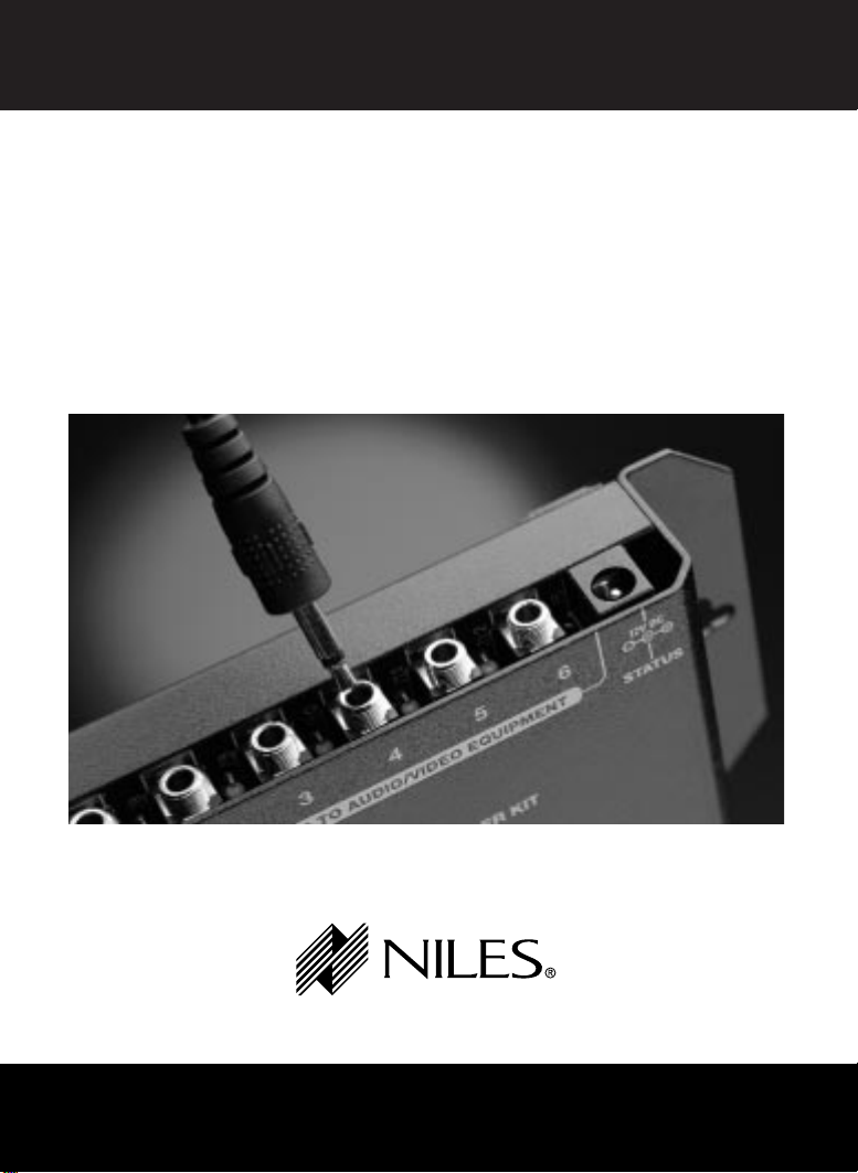
INSTALLATION AND OPERATION GUIDE
Remote Control
™
Anywhere!
Kit
B LENDING H IGH F IDELITY AND A RCHITECTURE
®
Page 2

PRECAUTIONS
IMPORTANT INFORMATION
The Remote Control Anywhere Kit is designed to provide
years of troublefree operation. For your protection, please
read these instructions thoroughly before proceeding
with your installation. Keep this manual for future reference.
Carefully observe and comply with all warnings,
cautions and operating instructions described in this manual.
WARNING
To avoid injury, the following basic safety precautions
will enable you to successfully install and use your
Remote Control Anywhere Kit.
© 1999 Niles Audio Corporation
1
Page 3

PRECAUTIONS
WARNINGS - To prevent possible injury, the following basic safety precautions should be observed in the installation and use of your Remote
Control Anywhere Kit.
1. Read through the entire manual - Before attempting any installation,
read this manual thoroughly and keep it for future reference.
2. Avoid contact with all high voltage electrical wiring and equipment!
3. Keep away from water and moisture - Never use or install electronic
products near water, ie., near a bathtub, sink, washing machine, in a wet
basement, near a swimming pool, or anywhere else the product may be
exposed to water or moisture.
4. Wall Adapter cord protection - Do not run the power cord where it may
be subject to wear or abuse. Do not allow anything to rest on or roll over
the power cord which may damage it.
6. Lightning - It is suggested that you remove the W all Adapter from the wall
if your system will not be used for long periods of time. Power surges due
to lightning strikes may damage your equipment.
7. Check your local building and electrical codes - There may be spe-
cific requirements regarding running low voltage in your area.
2
Page 4

TABLE OF CONTENTS
Introduction . . . . . . . . . . . . . . . . . . . . . . . . . . . . . . . . . . . . . . . . . . . . . . 4
Getting Started
Installation
Step 1 Placing the Connection Hub . . . . . . . . . . . . . . . . . . . . . . . . . . . . . . . 6
Step 2 Connecting the Sensor Cable to the Connection Hub . . . . . . . . . . . . . . 6
Step 3 Connecting the Sensor Cable to the Wall-Mount Sensor . . . . . . . . . . . . 7
Step 4 Connecting the 12V DC Wall Adapter and MicroFlashers . . . . . . . . . . . 8
Step 5 Mounting a MicroFlasher to A/V Components . . . . . . . . . . . . . . . . . . . 9
Step 6 Mounting the Connection Hub . . . . . . . . . . . . . . . . . . . . . . . . . . . . 11
Step 7 Finding the Right Spot to Install the Wall-Mount Sensor . . . . . . . . . . . 12
Step 8 Safety Check . . . . . . . . . . . . . . . . . . . . . . . . . . . . . . . . . . . . . . . . 13
Step 9 Cutting the Hole . . . . . . . . . . . . . . . . . . . . . . . . . . . . . . . . . . . . . 14
Step 10 Installing the Mounting Bracket . . . . . . . . . . . . . . . . . . . . . . . . . . . 15
Step 11 Running the Sensor Cable . . . . . . . . . . . . . . . . . . . . . . . . . . . . . . . 16
Step 12 Installing the Wall-Mount Sensor . . . . . . . . . . . . . . . . . . . . . . . . . . 17
Step 13 Reconnecting the Connection Hub . . . . . . . . . . . . . . . . . . . . . . . . . 18
System Operation
Optional Accessories
. . . . . . . . . . . . . . . . . . . . . . . . . . . . . . . . . . . . . . . . . . . 5
. . . . . . . . . . . . . . . . . . . . . . . . . . . . . . . . . . . . . . . . . . . . . . . . 6
. . . . . . . . . . . . . . . . . . . . . . . . . . . . . . . . . . . . . . . 19
. . . . . . . . . . . . . . . . . . . . . . . . . . . . . . . . . . . . 20
Running Sensor Cable in New Construction
Scheduling and Preparation . . . . . . . . . . . . . . . . . . . . . . . . . . . . . . . . . . . . . 22
Safety First! . . . . . . . . . . . . . . . . . . . . . . . . . . . . . . . . . . . . . . . . . . . . . . . . 22
Drilling . . . . . . . . . . . . . . . . . . . . . . . . . . . . . . . . . . . . . . . . . . . . . . . . . . . 23
Pulling the Cable . . . . . . . . . . . . . . . . . . . . . . . . . . . . . . . . . . . . . . . . . . . . 23
Concealing Sensor Cable in Existing Walls
. . . . . . . . . . . . 22
. . . . . . . . . . . . . . 23
Page 5
INTRODUCTION
The Remote Control
Anywhere! Kit enables you
to operate your remote
controlled audio/video
equipment from virtually any
location. Now you can place
your audio/video (A/V)
components out of sight
(behind cabinet doors, in the
rear of a room, or in a
different room) and still
conveniently control your
system.
Connection
Hub
Wall-Mount
Sensor
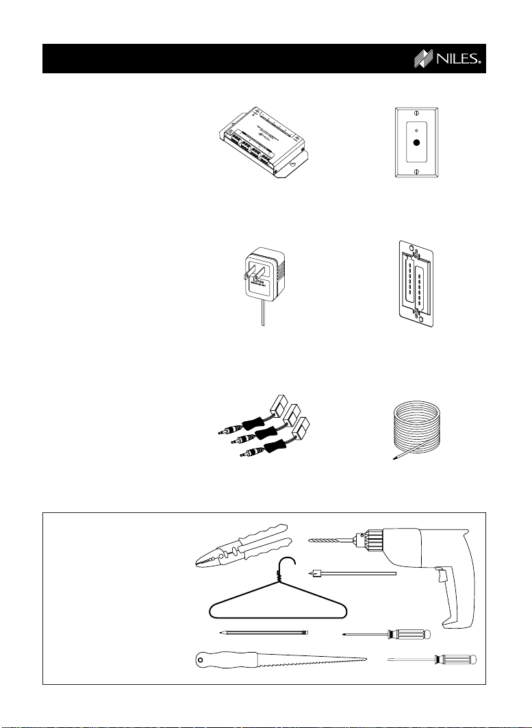
Kit Contents
Check that your Remote
Control Anywhere! Kit
contains the following:
• Connection Hub
• Wall-Mount Sensor
• 12V DC Wall-Adapter
• Mounting Bracket
• MicroFlashers (3)
• Sensor Cable (100ft)
Tools Needed
• pencil
• drywall saw
• standard screwdriver
• phillips screwdriver
• wire strippers
• drill (and assorted bits)
• wire coat hanger
12V DC
Wall Adapter
MicroFlashers (3)
4
Mounting
Bracket
Sensor Cable
(100ft)
Page 6
GETTING STARTED
While the Remote Control
Anywhere! Kit is compatible
with most brands of
audio/video components,
there are a few exceptions.
You should perform a
temporary hook-up to test
for compatibility before you
conceal wire or permanently
mount any parts.
Steps One through Five
describe how to perform a
quick and easy check for
compatibility.
Once you have determined
that all of your remote
controlled A/V components
are compatible, proceed
with the rest of the
installation.
5
Page 7
INSTALLATION
!
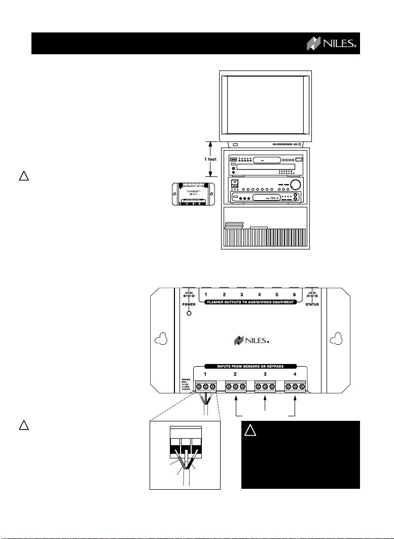
Step 1
Placing the
Connection Hub
Place the Connection Hub so
that the MicroFlasher wires
will reach the components.
!
Never place the
Connection Hub closer
than 1 foot away from a
television set. (See Figure 1)
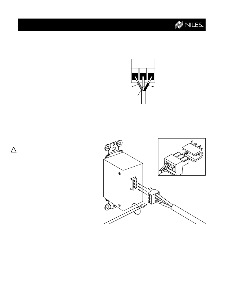
Step 2
Connecting the
Sensor Cable to the
Connection Hub
For your convenience, the
Sensor Cable ends have
been stripped. Insert one of
the stripped ends into the
INPUT connector on the
Connection Hub as shown
in Figure 2 and
tighten the screws.
!
The Cable must be connected as follows:
1 = Red
2 = Bare
3 = Black
Figure 1
Figure 2
Red
Bare
1
23
Black
REMOTE CONTROL ANYWHERE! KIT
CONNECTION HUB
Additional Sensors
Make sure that the
stripped ends of the wire
do not come in contact
with one another or any
surface other than the
connector.
6
Page 8
INSTALLATION
Step 3
CONTINUED
Connecting the
Sensor Cable to the
Wall-Mount Sensor
Pull out the removable
connector from the back of
the Wall-Mount Sensor.
Insert the other stripped end
of the Sensor Cable into the
removable connector on the
Wall-Mount Sensor and
tighten the screws.
(See Figure 3)
The cable must be
!
connected as follows:
1 = Red
2 = Bare
3 = Black
Plug the connector into the
connector socket on the
back of the Wall-Mount
Sensor. Make sure that the
orientation of the connector
is correct. (See Figure 4)
Figure 3
Figure 4
Red
Bare
1
23
Black
7
Page 9
INSTALLATION
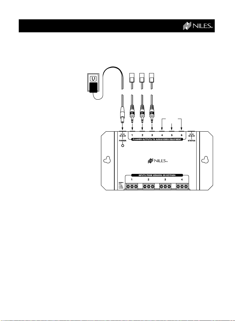
Step 4
CONTINUED
Connecting the
12V DC WallAdapter and
MicroFlashers
Plug the connector on the
supplied 12V DC WallAdapter into the socket
labeled POWER on the
Connection Hub and then
plug the wall adapter into
a live electrical outlet. The
power LED should light.
If the LED does not light,
confirm that the outlet
you used is live by plugging in a lamp.
Plug the MicroFlashers
into any of the sockets
labeled FLASHER OUTPUTS on the Connection
Hub. (See Figure 5)
Figure 5
Additional
Flashers
REMOTE CONTROL ANYWHERE! KIT
CONNECTION HUB
8
Page 10

INSTALLATION
CONTINUED
Step 5
Mounting a
MicroFlasher to A/V
Components
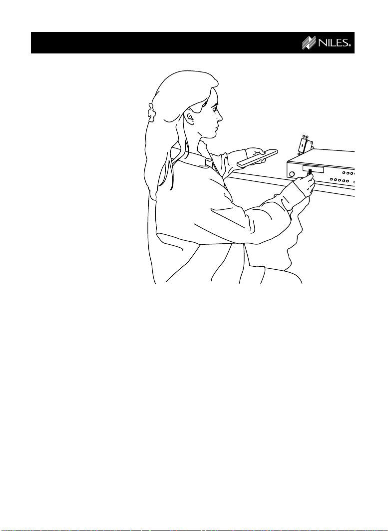
Make sure all of your remote
controls have batteries and
that they are able to operate
the A/V components.
Locate a place for the
remote control that is within
arm’s length of the A/V
components, yet cannot
directly control them. Place
the Wall-Mount Sensor no
closer than two feet in front
of the remote control.
(See Figure 6)
Hold the MicroFlasher four
inches in front of the remote
sensor window on the A/V
component’s front panel.
Press buttons on the remote
control while watching the
front panel of the A/V component. When the component responds repeatedly to
the commands, peel off the
protective backing on the
MicroFlasher and place the
MicroFlasher in that location.
Figure 6
continued
9
Page 11
INSTALLATION
If the A/V component’s
remote sensor is not clearly
marked, slowly move the
MicroFlasher over the window of the A/V component
while pushing buttons on the
remote control until you get
a response. (See Figure 7)
Repeat this procedure for
each A/V component you
wish to control.
When the A/V component
responds repeatedly, peel
off the protective backing on
the MicroFlasher and place
the MicroFlasher in that
location.
If you get no response at all,
call Niles Technical Support
at 1-800-289-4434.
(M-F 8:00 AM - 7:00 PM ET)
CONTINUED
Figure 7
10
Page 12

INSTALLATION
Step 6
CONTINUED
Mounting the
Connection Hub
Make sure that your
!
system tested OK before
proceeding
Once you have decided on
the ideal location for the
Connection Hub, unplug the
12V DC Wall-Adapter from
the electrical outlet and
disconnect the Wall-Mount
Sensor and the MicroFlasher
cables from the Connection
Hub. (See Figure 8) Also
remove the Sensor Cable
from the removable connector on the Wall-Mount
Sensor. (See Figure 9)
The Connection Hub can be
either mounted on a wall
using screws or placed on a
shelf using the included
adhesive feet.
(See Figure 10)
Figure 8
Figure 9
Figure 10
A: Wall mounting
B: If you desire to
shelf mount the
Connection Hub,
stick the included
adhesive backed
feet on the bottom
of the unit and
place it on the shelf
REMOTE CONTROL ANYWHERE! KIT
CONNECTION HUB
A
REMOTE CONTROL ANYWHERE! KIT
CONNECTION HUB
B
11
Page 13

INSTALLATION
Step 7
Finding the right
spot to install the
Wall-Mount Sensor.
Find a location in the
remote room that is convenient for you and where you
believe the Sensor Cable
from the Connection Hub
will easily reach.
If you have doubts about
!
whether you are capable of
installing a Niles Remote
Control Anywhere! Kit in
your walls, consult a Niles
dealer or professional
installer. They have special
tools, techniques, and
experience to make the
impossible possible. The
installer can provide you
with an estimate before
any work is done.
!
Do not install the
Wall-Mount Sensor in the
same electrical box with a
light switch or any other
high voltage device.
CONTINUED
!
Do not install the
Wall-Mount Sensor where
it will be exposed to
sunlight or any other
bright light.
!
Do not install next to TV’s,
fan motor switches, or
alarm panels.
12
Page 14
INSTALLATION
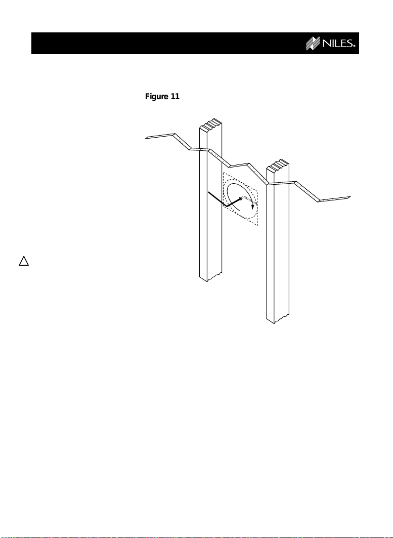
Step 8
CONTINUED
Safety Check
Once you have found your
installation spot, locate
nearby studs in the wall with
a stud sensor or by hand
knocking.
When you’ve found a
location that is free of studs,
drill a small 1/8” pilot hole
just barely through the
drywall. (See Figure 11)
!
Be careful. If you feel any
extra resistance as you
are drilling. STOP!
Cut a piece of coat hanger
and bend the wire to create
two right angles opposite of
each other about four inches long. Poke the four inch
end of the “Z-shaped” wire
into the pilot hole and rotate
in a complete circle while
probing the inside of the
wall for obstructions.
Figure 11
If the wire’s movement is
obstructed by a pipe, cable
or wall stud, fill the hole with
spackle or other patching
compound, sand, paint and
try another location.
13
Page 15
INSTALLATION
Step 9
CONTINUED
Cutting the hole
Once you have determined
the ideal position for the
cut-out, hold the Mounting
Bracket up to the wall
surface. Level the Mounting
Bracket and mark the wall
by tracing the inside
perimeter of the Mounting
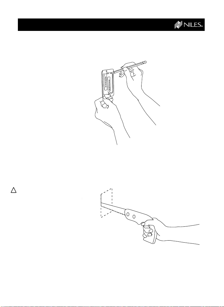
Bracket with a pencil.
(See Figure 12)
If you are cutting painted or
wall-papered drywall, use a
razor-knife to cleanly cut the
wallpaper. Then use a
drywall saw to cut the
drywall. (See Figure 13)
!
Be very careful not to saw
through existing wires,
pipes or structure.
Figure 12
Figure 13
14
Page 16

INSTALLATION
,
y
{
Step 10
CONTINUED
Installing the
Mounting Bracket
Place the Mounting Bracket
against the hole.
(See Figure 14)
Bend the tabs at a 90° angle
and insert into the hole.
(See Figure 15)
When the bracket is secure,
bend the tabs back against
the inside of the drywall and
insert the screws so that
they penetrate the tabs,
clamping the bracket to the
drywall. (See Figure 16)
Figure 14
Figure 15
Figure 16
15
Page 17

INSTALLATION
,,,
,,,
yyy
yyy
{{{
{{{
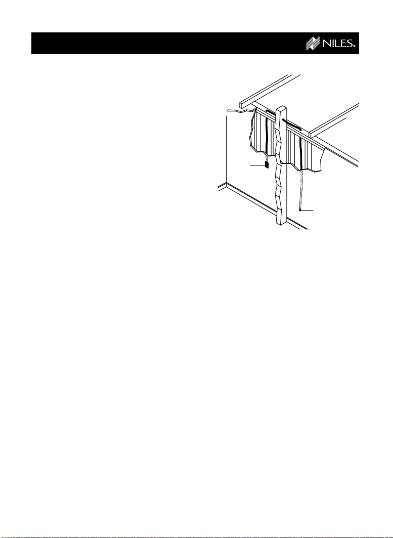
Step 11
CONTINUED
Running the
Figure 17
Sensor Cable
Conceal the Sensor Cable
between the Wall-Mount
Sensor hole and a new hole
near the Connection Hub.
(See Figure 17)
!
If you have doubts about
whether you are capable
of installing a Niles
Remote Control Anywhere!
Kit in your walls, consult a
Niles dealer or professional installer. They have special tools, techniques, and
experience to make the
impossible possible. The
installer can provide you
with an estimate before
any work is done.
Room 1 Room 2
Figure 18
1/4"
!
For more information, see
the section “Hints for
Concealing Wire” located
on page 23.
!
If you need to cut and
restrip the wire, make sure
that only 1/4” of wire is
exposed. Exposing too
much wire could create
“shorts” within the system. (See Figure 18)
Bare
16
1/4"
Page 18

INSTALLATION
Step 12
CONTINUED
Installing the
Wall-Mount Sensor
Reattach the Sensor Cable
to the Wall-Mount Sensor’s
removable connector
following the same
procedure as before.
(See Figure 18)
!
Connect the wires as
before:
1 = Red
2 = Bare
3 = Black
Plug the Sensor Cable
connector into the back of
the Wall-Mount Sensor.
Screw the Wall-Mount
Sensor to the bracket using
the supplied screws, then
screw the Decora®faceplate
into place using the supplied
faceplate screws.
(See Figure 19)
Figure 19
17
Page 19

INSTALLATION
!
Step 13
CONTINUED
Reconnecting the
Connection Hub
Connect the stripped ends
of the Sensor Cable into the
INPUT connectors on the
Connection Hub.
!
Connect the wires as
before:
1 = Red
2 = Bare
3 = Black
Plug the MicroFlashers into
the FLASHER OUTPUT
sockets on the Connection
Hub.
Plug the connector on the
12V DC Wall Adapter into
the POWER socket on the
Connection Hub and then
plug it into a live electrical
outlet. The POWER LED
should light. (See Figure 20)
That’s it! Now you are ready
to control your audio/video
equipment from the room
you chose.
Figure 20
Red
Bare
1
23
Black
Additional
Flashers
REMOTE CONTROL ANYWHERE! KIT
CONNECTION HUB
Additional Sensors
Make sure that the
stripped ends of the wire
do not come in contact
with one another or any
surface other than the
connector.
18
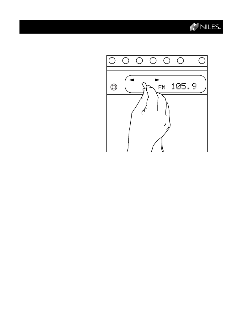
Page 20

SYSTEM OPERATION
Normal Operation
To control your audio/video
components, simply aim
your remote control at the
Wall-Mount Sensor.
If you are within range (and
your remote control’s
batteries are fresh), the LED
on the sensor will flash a
bright red color each time
you press a button on the
remote. (See Figure 21)
If you are using a remote
control with macro
capabilities (a single press
of a button issues a string
of commands), allow sufficient time for all of the
commands to execute.
Figure 21
19
Page 21

OPTIONAL ACCESSORIES
Additional
MicroFlashers
Although the Remote Control
Anywhere! Kit includes three
MicroFlashers, the Connection Hub can accommodate
up to six. Order model
IRC-2P (Stock# FG00726)
from your authorized Niles
dealer for each additional
A/V component you wish
to control.
Status Feedback
Wall Adapter
The Status Feedback
feature (see page 19) lights
the LED green on the Wall
Mount Sensor whenever your
system is on. This is a very
useful feature when operating
your equipment from a
remote location. For this feature to work, your system
receiver (or preamp) must
have a switched AC outlet
and you must purchase the
optional Status Feedback
12V DC Wall Adapter
(FG00665). The Status
Feedback Wall Adapter is
plugged into the switched AC
outlet of your receiver. The
12V DC output plug is inserted into the Connection Hub’s
Status Input. (See Figure 22)
IRC-2P MicroFlasher
Stock # FG00726
Figure 22
Switched outlet on
the back of receiver
or preamp.
12V DC Wall- Adapter
Stock # FG00665
20
™
REMOTE CONTROL ANYWHERE! KIT
CONNECTION HUB
Page 22

OPTIONAL ACCESSORIES
CONTINUED
Additional Sensors
Although the Remote Control
Anywhere! Kit includes one
Wall-Mount Sensor, the
Connection Hub can accommodate up to four Sensors
or Keypads. For additional
Wall Mount Sensors order
Model IRR4D+ White (Stock
number FG00643). Niles also
makes a variety of sensors
for virtually any application.
See your Niles dealer for
more information.
Double-Gang
Mounting Kit
Used for applications that
desire the mounting of two
Decora®style low-voltage
controls next to one another.
The kit includes a doublegang Decora faceplate and
an easy to install drywall
support. All necessary hardware is also included. Order
Double-Gang Mounting Kit
(Stock number FG00783).
Wall-Mount Sensor (IRR4D+) White
Stock # FG00643
Double-Gang Mounting Kit
Stock # FG00783
21
Page 23

INSTALLATION FUNDAMENTALS
Running Sensor
Cable in New
Construction
Scheduling and
Preparation
Plan to schedule the
sensor wiring after the electrical wiring is finished. That
way you can avoid cable
routes which could
potentially induce interference over the Sensor Cable.
The basic rules are:
Never run the Sensor
Cable through the same
hole as an electrical cable.
Never run the Sensor
Cable into the same J-box
as electrical cable.
Avoid running the Sensor
Cable beside the electrical
cable. Keep it at least 3 or
4 feet distant from any
electrical power cable.
As side-by-side wiring is
unavoidable in particular
spots in every house, just
move the Sensor Cable
route away as soon as
possible. If construction
forces a side by side run for
more than ten feet, install
metal conduit or shielded
Sensor Cable. Low-voltage
cables such as doorbells,
intercoms, telephone,
speaker, security, or television cannot cause interference on your Sensor
Cables, so you can safely
run all of them at the same
time, through the same
holes, side-by-side.
Safety First!
Wear gloves, safety goggles
and head protection when
drilling. Avoid nails, they ruin
bits and they can create
injury. Pay particular attention when using “hole-hogs”
and other powerful electric
drills; the torque of the drill
when suddenly stopped by
a nail can break a strong
person’s wrist.
Drilling
Use a bit that is large
enough for
the cables
you plan to
run. An auger
bit is the
preferred bit
for rough-in
wiring. It will
actually pull
itself through
the wood, so
that the drill
motor, not
you, does
most of the
Figure 23
work. You will be drilling a lot
of holes, so this is important.
Always drill the holes in the
center of the stud. If you
have to notch the stud or
drill the hole closer than one
inch from the edge of the
stud, protect the cable with
a nail plate (See Figure 23).
When drilling holes in ceiling
joists, drill in the center of
the joists and try to locate
the hole near the end of the
joist. DO NOT drill through a
“gluelam” or any load
bearing beam without the
direction of your contractor.
Try to line the holes up
perfectly, because it makes
pulling the cable much
easier. A good technique is
to snap a chalk line across
the face of the studs or
22
Page 24
INSTALLATION FUNDAMENTALS
against the bottom of the
ceiling joists. Then work
backward so that you can
always see the holes you
have already drilled. Paying
careful attention to this will
save you a lot of time later!
Pulling the Cable
Whenever you run the cable
farther than 4-1/2 feet from
a hole in a stud or joist
(open attic space, going up
walls, etc.), fasten the cable
to the joists or studs using
cable clamps or appropriately sized cable staples.
The cable should not have
large sags in it, nor should it
be too tight. Try to protect
the cable from being
stepped on in attics or other
unfinished crawl spaces.
There are guard strips, raceways and conduits which
can be used to protect the
cable. Consult the local
building code for special
requirements in your area.
Concealing
Sensor Cable in
Existing Walls
This is actually a fairly
simple task if you restrict
your choice of the WallMount Sensor location and
cable routes to the interior
walls or ceilings of
your home. Interior
walls in almost all
North American
residences are hollow, so that it is
easy to flush
mount the
Wall-Mount
Sensor into them
and route new
Sensor Cable
around the house.
What you see
when you look at
the painted wall
board, plaster, or paneling is
only the skin of the wall.
Behind the skin is the skeleton; two-by-four wood or
metal “studs” running vertically from the floor to the
ceiling in walls and 2 x 6 or
larger “joists” running horizontally in the ceilings and
floors. In between the studs
and the joists is the space
for the wiring and plumbing
of your home.
Exterior walls are different.
They must insulate the
house from the heat and
cold outside, so they are
stuffed with insulation. The
national building code
requires that the hollow wall
space in exterior walls be
broken by a horizontal stud
placed between the vertical
studs. This “fire blocking”
23
Figure 24
Wall-Mount
Sensor
Location
Stereo
Location
makes it very difficult to
retrofit long lengths of cable.
In some areas of the country
the exterior walls are
constructed of solid
masonry, and have no
hollow space for cables.
Start by examining all the
possible routes you might
take to run the Sensor Cable
from the Wall-Mount Sensor
location to the A/V components to be controlled. Use a
stud sensor or other device
to locate the internal
structure of the wall. You
want to avoid all studs or
joists. A typical route (See
Figure 24) would be from
the Wall-Mount Sensor location up the inside of the wall
to a new hole drilled into the
top “plate” (horizontal 2 x 4
at the top of the inside of the
Page 25

INSTALLATION FUNDAMENTALS
wall), into the attic crawl
space, then down another
plate to the wall behind the
stereo system itself. The
other very common route is
through the bottom plate of
the wall into an unfinished
basement or crawl space.
Identify where all of your
electrical, phone, and TV
wiring is likely to be and
plan to route around it all.
You can accidentally induce
interference on your Sensor
Cable right beside electrical
cable for more than a few
feet. Try to keep Sensor
Cable running parallel to
power cables at least 3 feet
away. To find exactly where
an electrical cable is routed,
try inspecting the inside of
the wall by turning off the
breaker for a particular
power outlet or switch,
removing the cover plate
and switch or receptacle,
and shining a penlight into
the wall. If you have access
to an attic or basement
space, you can see which
part of the wall space is free
of obstructions
(See Figure 25).
When you don’t have
access above or below the
wall, try to estimate the
existing cable and pipe
locations from the positions
Figure 25
Unobstructed space
for Sensor Cable
of electrical outlets and
plumbing fixtures on both
sides of the wall. Also, take
a look at the outside of your
house, sometimes a conduit, vent or drain pipe will
be visible and will offer useful information. Choose the
route with the fewest
potential obstacles.
If your house is built on a
slab or you are wiring
between two finished floors,
look for baseboards which
could be removed and
replaced with the cable
behind them. Doorjambs
can be removed and often
have enough space for
Sensor Cable all the way
around the door
(See Figure 26).
Sometimes, an under-thecarpet run is possible. As a
last resort, heating and air
conditioning vents can be
24
used as cable raceways for
plenum rated cable (check
your local building codes,
some municipalities require
a conduit).
In traditional wood
stud/drywall construction
you can cut the hole for the
Wall-Mount Sensor and
utilize the hole to auger
holes across, up or down
Figure 26
Page 26

INSTALLATION FUNDAMENTALS
the wall for as far as your
drill bit will take you. If you
have matching paint and
take reasonable care in
patching you can cut a
hatch in the drywall at each
stud, run your cable, and
patch and touch-up the wall
(See Figure 27).
When you are dealing with
the unknown because of
the structure of your home,
or with difficult materials to
patch the wall, such as
plaster, lath and plaster,
faux finishes, wallpaper etc.,
be patient. A careful study
of the potential problems
before you start the job will
pay off later.
Figure 27
25
Page 27

Niles Audio Corporation
12331 SW 130th Street Miami Florida 33186
TEL: (305) 238-4373 FAX: (305) 238-0185
www.nilesaudio.com
©1999 All Rights Reserved. Niles Audio Corporation. Because Niles strives to continuously improve its products, Niles
reserves the right to change product specifications without notice. Niles, the Niles logo and Blending High Fidelity and
Architecture are registered trademarks of Niles Audio Corporation. Decora is a registered trademark of Leviton
Manufacturing Company. Remote Control Anywhere, MicroSensor and MicroFlasher are trademarks of Niles Audio
Corporation. Printed in the USA 8/98 DS00224B
 Loading...