

Page 1
DIRECTED SOUNDFIELD
INSTALLATION GUIDE
™
DESIGNER AESTHETICS
ADVANCED TECHNOLOGY
Page 2
DIRECTED SOUNDFIELD
™
CONGRATULATIONS!
Thank you for choosing Niles DS Loudspeakers. With proper installation, use,
and care, your loudspeakers will deliver years of listening enjoyment. Niles
manufactures the industry’s most comprehensive line of custom installation
components and accessories. For information on our complete product
assortment, please visit us at: www.nilesaudio.com.
TABLE OF CONTENTS
Introduction 3
Features and Benefits 3
Parts Guide 4
Installation Considerations 4
Installing the Loudspeakers 6
Adjusting the Pivoting Woofer and Tweeter 8
Switch Adjustments 9
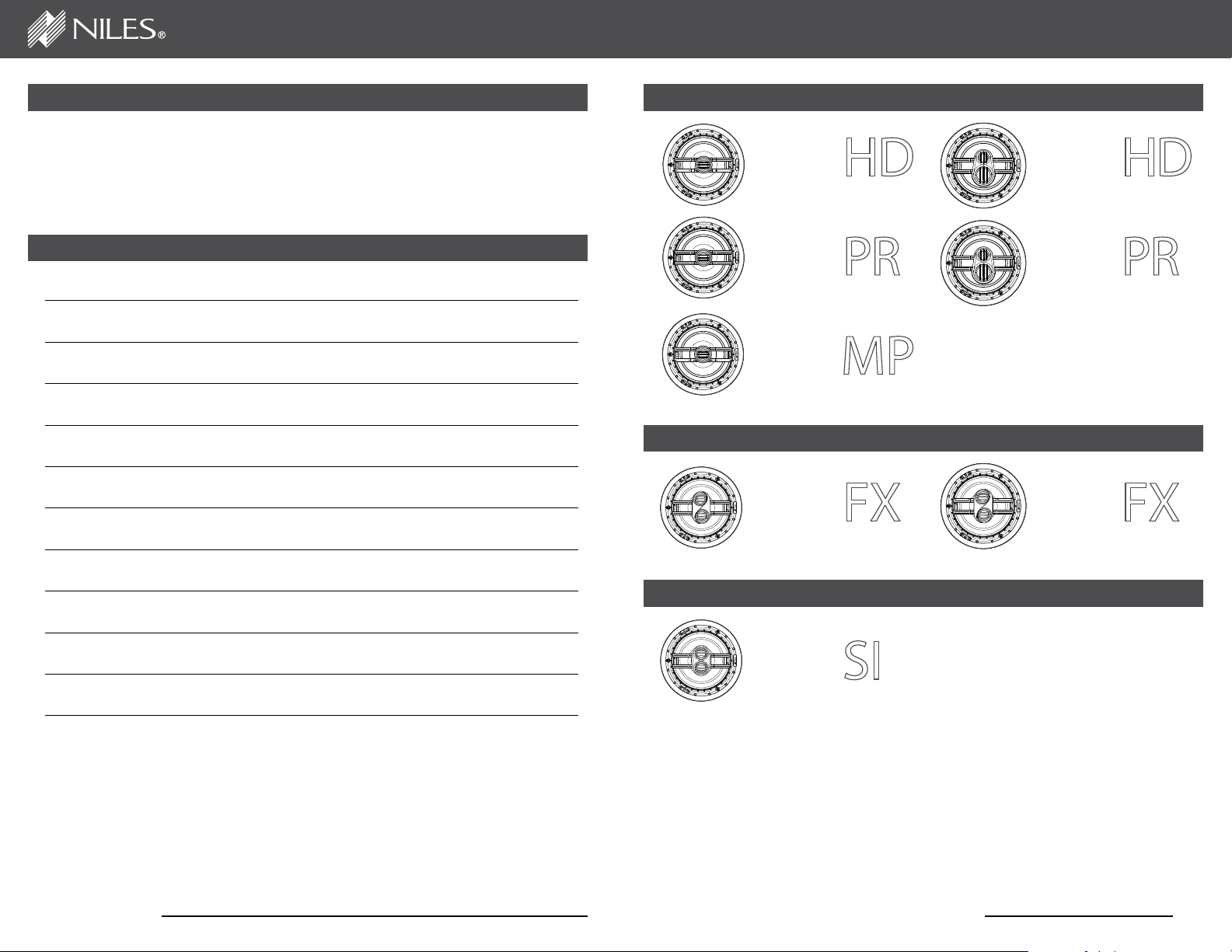
LEFT/CENTER/RIGHT CEILING-MOUNT LOUDSPEAKERS
DS7
DS7
DS8
DS8
DS7
SURROUND EFFECTS CEILING-MOUNT LOUDSPEAKERS
DS7 DS8
Painting the Grilles 9
Installing the Grilles 9
Applications 10
Specifications 12
WWW.NILESAUDIO.COM
STEREO INPUT CEILING-MOUNT LOUDSPEAKER
DS7
NILES AUDIO CORPORATION – 1-800-BUY-HIFI – 1-760-710-0992
2
Page 3
DIRECTED SOUNDFIELD
™
INTRODUCTION
Niles DS Loudspeakers deliver an uncompromising combination of designer
oriented aesthetics, superb sound performance, and ease of installation. Small
footprint and low prole, MicroThin™ magnetically attached grilles provide the
look that homeowners desire. Available in 7” and 8” versions, there are left/center/
right, surround effects, and stereo input models to satisfy applications ranging
from advanced home theaters to distributed audio systems. Niles’ patented
Directed Soundeld™ pivoting woofer technology precisely directs the sound to
the listening area for the best possible audio performance.
FEATURES AND BENEFITS
DESIGNER AESTHETICS
Magnetically attached MicroThin™ round speaker grilles ensure a clean,
unobtrusive designer appearance that blends with the room’s aesthetics. Optional
square grilles provide added design exibility.
SUPERIOR SOUND QUALITY
Patented Directed Soundeld™ technology* precisely directs the sound to the
listening area for better sound quality. New patent-pending pivot mechanism
provides for smooth adjustment and holds the loudspeaker securely in position.
PARTS GUIDE
PACKAGE CONTENTS:
DS7MP, DS7PR, DS7HD, DS8PR, DS8HD, DS7SI
(1) Niles DS loudspeaker, (1) Magnetically attached round grill, (1) Hole template
with painting standoffs, (1) Owner’s manual with warranty information
PACKAGE CONTENTS: DS7FX, DS8FX
(2) Niles DS loudspeakers, (2) Magnetically attached round grilles, (2) Hole
templates with painting standoffs, (1) Owner’s manual with warranty information
INSTALLATION CONSIDERATIONS
Recommended tools for installation:
• Cordless screwdriver • Measuring tape • Painters tape
• One inch #2 Phillips tip • Stud nder • Drop cloth
• 1/8” Drill bit • Spackle • Optional - a 24” x 24”
• Drywall saw • Wire stripper
• Laser plumb bob • Cable ties
• 12” -14” Coat hanger wire • Pencil
piece of R19 insulation
INSTALLATION EASE
Three patent-pending, spring tensioned mounting clamps permit quick installation
and compensate for uneven mounting surfaces and varied environmental
conditions. Weather-resistant construction enables installation in moist areas such
as bathrooms or outdoors under eaves.
INSTALL WITH CONFIDENCE
The best-built loudspeakers deserve the best protection—the Niles Lifetime
Limited Warranty.
* U.S. Patent 6,070,694
WWW.NILESAUDIO.COM NILES AUDIO CORPORATION – 1-800-BUY-HIFI – 1-760-710-0992
7” DS LOUDSPEAKERS
These require an 8-1/2” (21.6 cm)
diameter hole opening and a
minimum of 6” (15.25 cm) depth
when measured from the exterior
face of the drywall. To the sides
of the hole you will need 1” for
the mounting tabs to clamp the
speaker to the drywall.
8” DS LOUDSPEAKERS
These require a 9-3/4” (24.8
cm) diameter hole opening and
depth of 6” (15.25 cm) from the
face of the drywall. To the sides
of the hole you will need 1” for
the mounting tabs to clamp the
speaker to the drywall.
6” (15.25 cm)
Depth Behind
Drywall
DS7 8-1/2” (21.6 cm)
DS8 9-3/4” (24.8 cm)
Diameter Hole Opening
Figure 1. Required dimensions for installation in ceiling.
(CONTINUED ON NEXT PAGE)
43
Page 4

DIRECTED SOUNDFIELD
™
INSTALLATION CONSIDERATIONS CONTINUED
If you are going to use the optional
Niles Rear Wave Enclosure, you will
need an additional 2” of depth and
10” clearance to one side of the
loudspeaker opening.
NOTE: BE VERY CAREFUL WHEN LOCATING
THE SPEAKERS. VERIFY ALL LOCATIONS
ARE CLEAR OF OBSTRUCTIONS BEFORE
CUTTING THE FIRST HOLE.
Each speaker requires two-conductor wiring of sufcient gauge. The gauge
depends on the length of the wire. For recommendations, please refer to (Figure 2).
(Stereo Input loudspeakers require four-conductor wiring).
RWE Rear Wave Enclosure*
RWE-7C Stock# FG01643
RWE-8C Stock# FG01644
Distance from speaker to amplifier Wire Gauge
Less than 80 feet
16
80 to 200 feet 14
More than 200 feet 12
INSTALLING THE LOUDSPEAKERS
It is often easier to lay the speakers out on the oor and then transfer the
locations to the ceiling with a laser plumb bob. If you are using new construction
brackets, place string across the centers of the bracket to provide a way to align
the bracket to the laser. Remember, you will need 1” to the sides of the mounting
hole for the mounting clamps to secure the speaker to the drywall.
1. Once you have determined a possible position for the hole cutout, drill a
1/8” pilot hole just barely through the ceiling (1/2” to 5/8” deep in most
homes) in the center of your proposed loudspeaker location. BE VERY
CAREFUL NOT TO DRILL THROUGH EXISTING WIRES, PIPES, OR
STRUCTURE. IF YOU FEEL ANY EXTRA RESISTANCE AS YOU ARE
DRILLING, STOP.
2. Cut a foot-long piece of coat hanger. Bend the wire (creating a right
angle) leaving 5-1/2” at one end (this allows for the extra width of the
mounting dogs). Poke the “L-shaped” wire into the pilot hole and turn it
in a complete circle and move it into the ceiling cavity to make sure you
have approximately 6” of depth. If the wire’s movement is obstructed by
anything, fill the hole(s) with spackle and try another location. (If there
is any risk of uninsulated electrical connections within the ceiling area,
use insulating gloves or other materials or consult with an installation
professional before proceeding).
Figure 2. Speaker Wire Gauge Guide
When running loudspeaker wire inside walls or ceilings, use special jacketed
cable (CL-2 or CL-3 rating) to protect the wire and for re prevention. In some
municipalities, conduit is required. For a trouble-free installation, low voltage wire
such as loudspeaker wire must be in accordance with the National Electrical Code
and any applicable provisions of the local building code. If you are unsure of the
correct installation techniques, wire jacket, or type of conduit to use, consult a
professional audio/video installer, building contractor, or the local building and
inspection department.
Not for use with SI Speakers
*
WWW.NILESAUDIO.COM NILES AUDIO CORPORATION – 1-800-BUY-HIFI – 1-760-710-0992
3. If the coat hanger moves freely in a complete circle and you have
sufficient depth, tape the template to the ceiling and proceed to layout the
other speakers. Once you are comfortable with all speaker locations, use
a pencil to lightly outline the circular template.
4. Drill the starting point of your cut with a 1/4” bit.
5. If you are cutting drywall, use a sheetrock or keyhole saw. Cut the hole
with the saw at a 45° angle. That way the drywall section can be replaced
cleanly if there is an unseen obstruction behind the wall. IMPORTANT: BE
VERY CAREFUL NOT TO SAW THROUGH EXISTING WIRES, PIPES,
OR STRUCTURE. IF YOU FEEL EXTRA RESISTANCE AS YOU ARE
CUTTING, STOP.
NOTE: DO NOT INSTALL LOUDSPEAKERS BEFORE THE DRYWALL HAS BEEN COMPLETELY
FINISHED AND PAINTED.
(CONTINUED ON NEXT PAGE)
65
Page 5

DIRECTED SOUNDFIELD
™
INSTALLING THE LOUDSPEAKERS CONTINUED
6. Prep the speaker wire by stripping 1/4”-1/2” from each speaker lead.
Twist the strands or tin the leads with solder to ensure there are no stray
strands that could short and possibly harm the amplifier.
7. If you’ve chosen to use insulation behind the loudspeaker, place it through
the hole and center it on the opening. If using paper-backed insulation, it
should be placed so that the paper side is away from the loudspeaker.
8. The speaker has black and red
spring-loaded connectors (Figure 3).
Black is for the negative (-) wire and
red for the positive (+). It is important
to observe correct wiring polarity.
This is especially important for the
Stereo Input (SI) Loudspeaker. If
you have wire other than black and
red, make sure you connect it the
same on the amplifier end as the
speaker end. Failure to do so will
Figure 3. Spring-loaded speaker wire
connectors.
adversely affect the loudspeakers’
performance.
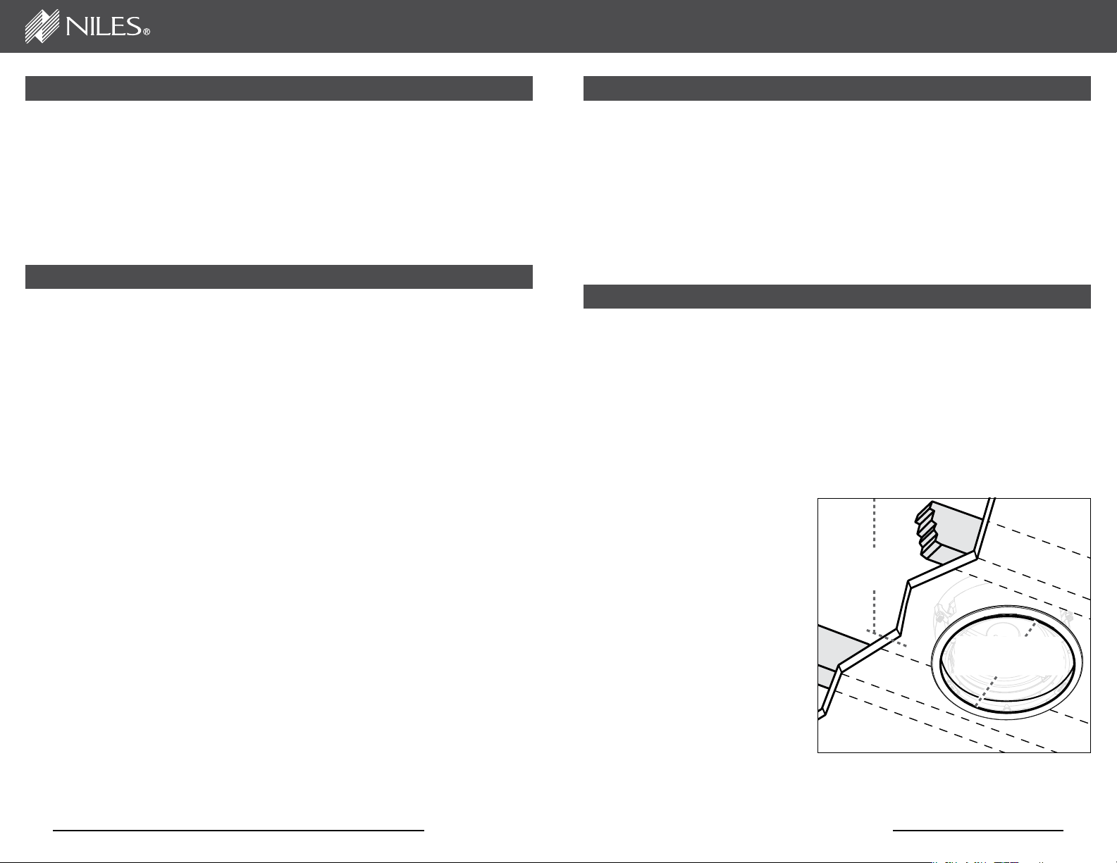
9. Once the speaker wires are
connected, carefully slide the
loudspeaker into the opening hole
(Figure 4). While holding the speaker
in place, tighten the mounting screws
to secure the speaker to the drywall.
We recommend using a motorized
screwdriver. Be careful not to over
tighten. The DS loudspeakers feature
spring loaded mounting clamps that
allow the speaker to remain flush
with the ceiling, even if the
drywall shifts or expands.
ADJUSTING THE PIVOTING WOOFER AND TWEETER
DS loudspeakers feature the patented Directed Soundeld™ woofer pivot
mechanism that enables the loudspeaker to direct the sound to the listening area
(Figure 5). The tweeter(s) pivot independently of the woofer to provide additional
control of the sound. Adjusting the woofer angle will affect the tweeter angle, so
always begin by adjusting the woofer.
1. Press the outside edge of the woofer on the plastic, not the rubber, and
slide the speaker until it is facing the primary listening position. The
woofer adjusts approximately 15-degrees. Do not force the speaker.
2. After adjusting the woofer, adjust the tweeter by pressing on the outside
edge of the tweeter to point to the listening area.
Figure 5. Aim woofer and tweeter towards listener area.
NOTE: DO NOT CARRY THE SPEAKER
BY THE TWEETER OR TWEETER
BRIDGE. THIS MAY DAMAGE THE
SPEAKER.
Mounting clamps require
1” clearance to the sides
of the hole opening
Figure 4. Installing a
DS loudspeaker.
WWW.NILESAUDIO.COM NILES AUDIO CORPORATION – 1-800-BUY-HIFI – 1-760-710-0992
87
Page 6

DIRECTED SOUNDFIELD
™
SWITCH ADJUSTMENTS
TWEETER SWITCH
(DS7MP, DS7PR, DS7HD, DS8PR, DS8HD, DS7SI)
The three-position tweeter switch allows you to adjust the high frequency output
of the loudspeaker to compensate for room acoustics. The center position does
not affect the tweeters output. Moving the switch to the – position reduces the
tweeter output by 3 dB to compensate for bright rooms (tile or wood oors, spare
furnishing, tall ceilings). Moving the switch to the + position increases the tweeter
output by 3 dB to compensate for absorptive rooms (carpeting, lots of drapery,
plush furniture, etc.).
DIALOG COMPENSATION SWITCH
(DS7MP, DS7PR, DS7HD, DS8PR, DS8HD, DS7SI)
This switch provides additional denition at critical midrange frequencies where
the human voice is reproduced. This switch is generally used only for home
theater center speaker applications. Engage the switch if you wish to enhance
the dialog.
DIFFUSE / DIRECT SWITCH (DS7FX, DS8FX)
Use the Diffuse setting for movies and general music listening since most lms
are mixed using non-localized surround effects and music is usually recorded in a
favorable acoustic environment. Use the Direct setting for discrete multi-channel
recordings that equally emphasize front and surround sounds. For 7.1-channel
surround sound systems, use the Diffuse setting on the side effects loudspeakers
and the Direct setting for the rear effects loudspeakers.
PAINTING THE GRILLES
The DS loudspeaker grilles can be painted without priming, but the fabric scrim
must rst be removed. The installation template has die cut standoffs that can be
used to position the grille off the ground while painting. Use several light coats
sprayed from different sides and angles to cover all surfaces and not ll in any
holes. If you do ll some holes, use compressed air to open them before the paint
dries. It may be helpful to dilute the paint.
APPLICATIONS
Niles DS Loudspeakers are designed to be installed in any standard ceiling.
When choosing a location, thought should be given to the sound coverage of the
loudspeaker, and ease of running the speaker wire.
STEREO SOUND APPLICATIONS
The best stereo effect will be achieved if both
loudspeakers are at an equal distance from the
listening area. Ideally all loudspeakers should
8'
be on the same horizontal plane (Figure 6). Avoid
installing loudspeakers near corners to prevent
3-6'
3-6'
8'
a “boomy” or diffracted sound. Also note that
the lower the ceiling, the closer the loudspeaker
should be placed to the listener.
Figure 6. Stereo Sound Application.
HOME THEATER APPLICATIONS
Left/Center/Right – Position the center
channel loudspeaker directly over the
television, with the left and right speakers
equidistant from the center. The separation
between the left and right should not be
LCR
LCR
LCR
more than the distance to the primary
seating area (Figure 7).
Side Surround Effects – Position surround
effects loudspeakers to the sides of the
FX
FX
listening area with the tweeters in-line with
the listener. The tweeters should point to
the front and rear of the room (Figure 7).
Rear Surround Effects – Position surround
FX
Critical
Listening
Position
FX
effects loudspeakers behind the listening
area, to the inside of the front left and right
speakers. The tweeters should point to the
sides of the room (Figure 7).
Figure 7. Home Theater Application.
INSTALLING THE GRILLES
The Niles MicroThin™ speaker grille installs magnetically over the speaker.
Carefully center the grill over the speaker and let the magnets do their work,
verifying that the grill sets ush against the ceiling at all edges.
WWW.NILESAUDIO.COM NILES AUDIO CORPORATION – 1-800-BUY-HIFI – 1-760-710-0992
(CONTINUED ON NEXT PAGE)
109
Page 7

DIRECTED SOUNDFIELD
™
APPLICATIONS CONTINUED
SINGLE SPEAKER STEREO INPUT APPLICATIONS
Stereo Input loudspeakers are ideal for small rooms where positioning two
loudspeakers is not practical. Examples would be a small kitchen, bathroom,
hallway, or small bedroom. Locate the loudspeaker as close to the center of the
room as possible for the most even distribution of sound (Figure 8). Avoid installing
the loudspeaker near a corner to prevent a “boomy” or diffracted sound.
Figure 8. Single Loudspeaker Stereo Input Application.
SPECIFICATIONS
Model Woofer
7” glass
fiber woofer
DS7MP
DS7PR.
DS7HD
DS7FX
DS7SI
DS8PR
DS8HD
DS8FX
cone
7” glass
fiber woofer
cone
7“ IMPACT
(Improved
Aluminum
Ceramic
Technology)
cone
7” glass
fiber woofer
cone
7” glass
fiber woofer
cone
8” glass
fiber woofer
cone
8” IMPACT
(Improved
Aluminum
Ceramic
Technology)
cone
8” IMPACT
(Improved
Aluminum
Ceramic
Technology)
cone
Tweeter /
Midrange
1” UltraSilk®
soft dome
1” fluid-cooled
Teteron® dome
1” nano-coated
IMPACT dome
Dual 1”
fluid-cooled
Teteron®
domes
Dual 1”
UltraSilk® soft
domes
1” fluid-cooled
Teteron®
dome / 1-1/2”
fluid-cooled
Teteron® dome
1” nano-coated
IMPACT dome
Dual 1” nano-
coated IMPACT
domes
Recommended
Amplifier Power
10-130 watts
10-130 watts
10-160 watts
10-140 watts
10-130 watts
10-140 watts
10-160 watts
10-160 watts
Normal
Impedance
8 ohm nominal;
6 ohm minimum
8 ohm nominal;
6 ohm minimum
8 ohm nominal;
6 ohm minimum
8 ohm nominal;
6 ohm minimum
8 ohm nominal;
6 ohm minimum
8 ohm nominal;
6 ohm minimum
8 ohm nominal;
6 ohm minimum
8 ohm nominal;
6 ohm minimum
Frame Dimensions
with Grille
9-7/8” (21.15 cm)
9-7/8” (21.15 cm)
9-7/8” (21.15 cm)
9-7/8” (21.15 cm)
9-7/8” (21.15 cm)
11-1/4” (28.52 cm)
11-1/4” (28.52 cm)
11-1/4” (28.52 cm)
Hole Cut-Out
Dimensions
8-1/2”
(21.6 cm)
8-1/2”
(21.6 cm)
8-1/2”
(21.6 cm)
8-1/2”
(21.6 cm)
8-1/2”
(21.6 cm)
9-3/4”
(24.76 cm)
9-3/4”
(24.76 cm)
9-3/4”
(24.76 cm)
Depth (5/8”
Drywall Ceiling)
5-5/16”
(13.6 cm)
5-5/16”
(13.6 cm)
5-5/16”
(13.6 cm)
5-5/16”
(13.6 cm)
5-5/16”
(13.6 cm)
5-5/16”
(13.6 cm)
5-5/16”
(13.6 cm)
5-5/16”
(13.6 cm)
Model Description Additional Depth Behind Ceiling Additional Side Clearance
RWE7C
RWE8C
7” Rear Wave Enclosure 1-13/16” 10”
8” Rear Wave Enclosure 1-15/16” 10”
WWW.NILESAUDIO.COM NILES AUDIO CORPORATION – 1-800-BUY-HIFI – 1-760-710-0992
1211
Page 8

BY PHONE (IN USA)
1-800-BUY-HIFI (289-4434)
BY PHONE (OUTSIDE USA)
+1 (760) 710-0992
CUSTOMER SERVICE HOURS
8:00 AM to 5:30 PM ET
TECHNICAL SUPPORT HOURS
8:00 AM to 7:00 PM ET
ON THE WEB
www.nilesaudio.com
EMAIL TECHNICAL SUPPORT
techsupport@nilesaudio.com
EMAIL FOR PRODUCT SUGGESTIONS
productsuggestions@nilesaudio.com
DIRECTED SOUNDFIELD
™
LIMITED WARRANTY
Niles Audio Corporation (“NILES”) warrants to the original retail purchaser only that this product will be free of manufacturing defects
in material and workmanship for the following periods and subject to the limitations and exclusions set forth below:
Lifetime Warranty
All Passive Loudspeaker Products (those not requiring AC or battery power).
Ten years from the date of purchase
All Other Passive Products (those not requiring AC or battery power).
Two years from the date of purchase
All Active Products (those requiring AC or battery power).
This warranty is not transferable to subsequent purchasers of the product. To obtain warranty service, contact the authorized dealer
where you purchased your product or take the unit to the nearest authorized NILES dealer (with proof of purchase – claims made
without proof of purchase will be denied) who will test the product and if necessary, forward it to NILES for service. If there are no
authorized NILES dealers in your area, you must contact NILES to receive a factory Return Authorization Number. DO NOT RETURN
ANY UNIT WITHOUT FIRST RECEIVING WRITTEN AUTHORIZATION AND SHIPPING INSTRUCTIONS FROM NILES.
Upon examination, NILES will, at its sole option and expense, repair or replace any product found to be defective. NILES will return
the repaired or replaced unit to you via its usual shipping method from the factory to your address in the United States of America or
Canada only. Any shipping costs for addresses outside of the United States or Canada shall be the responsibility of the purchaser.
In the event that this model is no longer available and cannot be repaired effectively, NILES, at its sole option, may replace it with
a different model of equal or greater value, or refund the original purchase price paid. THE FOREGOING ARE YOUR EXCLUSIVE
REMEDIES FOR BREACH OF WARRANTY.
This Warranty does not include service or parts to repair damage caused by improper use or handling, including but not limited to
damage caused by accident, mishandling, improper installation, commercial use, abuse, negligence, or normal wear and tear, or any
defect caused by repair to the product by anyone other than NILES.
This warranty does not cover reimbursement for your costs of removing and transporting the product for warranty service
evaluation, or installation of any replacement product provided under this warranty.
This Warranty will be void if:
•the Serial Number on the product has been removed, tampered with or defaced.
• the product was not purchased from an authorized dealer or reseller.
THE FOREGOING WARRANTIES ARE EXCLUSIVE AND IN LIEU OF ALL OTHER EXPRESSED AND IMPLIED WARRANTIES.
NILES EXPRESSLY DISCLAIMS ALL SUCH OTHER WARRANTIES, INCLUDING BUT NOT LIMITED TO IMPLIED
WARRANTIES OF MERCHANTABILITY, FITNESS FOR A PARTICULAR PURPOSE AND NON-INFRINGEMENT, WITH RESPECT
TO THE PRODUCT. TO THE MAXIMUM EXTENT PERMITTED BY LAW, NILES SHALL NOT BE RESPONSIBLE FOR ANY
INCIDENTAL OR CONSEQUENTIAL DAMAGES EXCEPT TO THE EXTENT PROVIDED (OR PROHIBITED) BY APPLICABLE
LAW, EVEN IF NILES HAS BEEN ADVISED OF THE POSSIBILITY OF SUCH DAMAGES.
Notwithstanding the above, if you qualify as a “consumer” under the Magnuson-Moss Warranty Act, or applicable state laws, then
you may be entitled to any implied warranties allowed by law for the Warranty Period. Further, some states do not allow limitations
on how long an implied warranty lasts or allow the exclusion or limitation of consequential damages, so such limitations may not
apply to you. This warranty gives you specific legal rights, and you may also have other rights which vary from state to state.
For the name of your nearest authorized NILES dealer, contact: NILES AUDIO CORPORATION, 1969 Kellog Avenue, Carlsbad,
CA 92008, or call 1-800-289-4434, 1-760-710-0992. Please be advised that NILES only sells its products via the Internet through
a select group of authorized Internet dealers. These are listed on our website at www.nilesaudio.com. Products offered on the
Internet through unauthorized Internet dealers are not covered by the NILES warranty and may be either:
1) goods acquired on a secondary or grey market
2) counterfeit or stolen goods
3) damaged, or defective goods
13
WWW.NILESAUDIO.COM
Please fill in your product information and retain for your records.
Model ______________________ Serial No. _____________________________________________ Purchase Date ______________
ATTENTION: TO OUR VALUED CONSUMERS:
To insure that consumers obtain quality pre-sale and after-sale support and service, NILES products are sold exclusively through
authorized dealers. This warranty is VOID if the products have been purchased from an unauthorized dealer.
Page 9

1-800-BUY-HIFI – 760-710-0992 – www.nilesaudio.com
©2011 The AVC Group, LLC. All rights reserved. Niles and the Niles logos, UltraSilk,
Blending High Fidelity and Architecture are registered trademarks of The AVC Group,
LLC. Directed Soundfield and MicroThin are trademark of The AVC Group, LLC. All other
trademarks are the property of their respective owners. Designed and Engineered in the USA.
Made in China. DS00719B
 Loading...