

Page 1
Series 710 UHMWPE
Lined Butterfly Valves
Installation Instructions
Nil-Cor Reserves The Right To Change Product
And Performance Specifications Without Notice
Nil-Cor Recommends
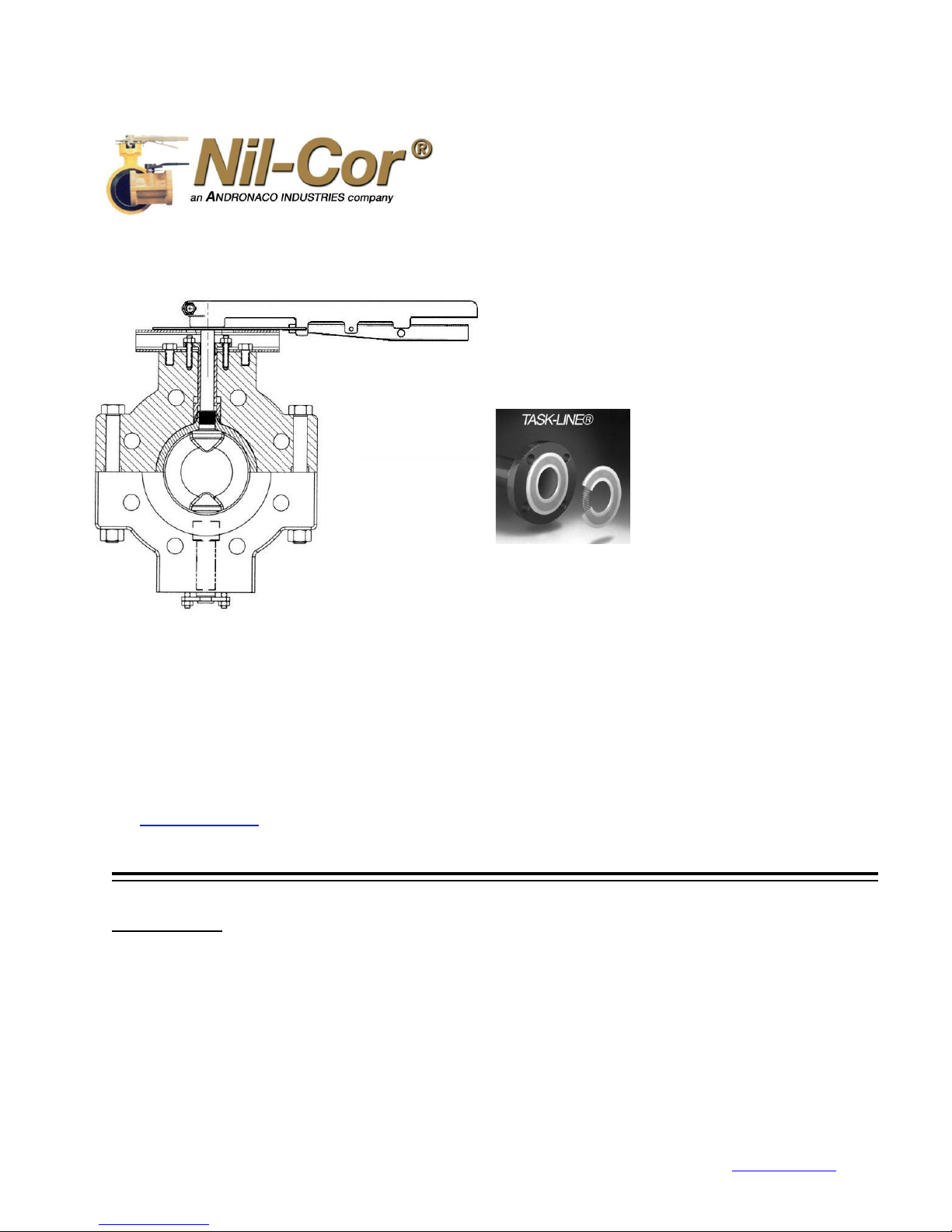
Installation with Task-
Line Gaskets. See
Page 2 for details..
Task-Line gaskets are
available from your NilCor Distributor.
This instruction is intended for use by
persons having technical skill and valve
installation experience, at their own
discretion and risk.
Questions regarding this instruction should
be directed to Nil-Cor Customer Service or
your authorized stocking distributor. A
distributor list can be found on the Internet
at: www.nilcor.com.
Initial Inspection
1. Do not remove protective covers until just prior to the
valve installation. If covers are removed for
inspection, they should be replaced immediately
afterward. This precaution is to protect the sealing
faces from damage during storage and handling
operations.
2. Match the serial number on valve nameplate with the
serial number on the enclosed warranty card. If the
numbers match, please complete the warranty card
3/10/2016 4855 Broadmoor Ave. Kentwood, MI 49512 Phone: (616) 554-3100 Fax: (616) 554-5623 www.nilcor.com
Nil-Cor UHMWPE-Lined Composite Butterfly
Valves offer superior shutoff performance in
a wide range of corrosive and erosive media
and unmatched protection from external
corrosion. At less than half the weight of
lined iron valves, they are less costly to
transport, install and support. This
installation instruction will help you obtain
the full benefit of the world’s best-performing
lined butterfly valves.
and mail back to Nil-Cor If the numbers do not
match, contact Nil-Cor Customer Service.
3. Check the valve nameplate before installation to
ensure that the pressure rating and materials of
construction are compatible with the intended
service conditions.
4. Inspect adjoining pipelines and remove any material
that could damage the valve liner during installation.
Nil-Cor. LLC
1
Page 2
2
Installation Instructions
710 UHMWPE
SIZE
GLAND TORQUE
(IN-LBS)
RE-TORQUE, MIN
(IN-LBS)
2”
30-40
30
3”
40-50
30-40
4”
50-60
40-50
6”
80-90
50-70
8”
90-100
60-80
10”
100-110
70-90
12”
100-110
70-90
Check Disc Clearance
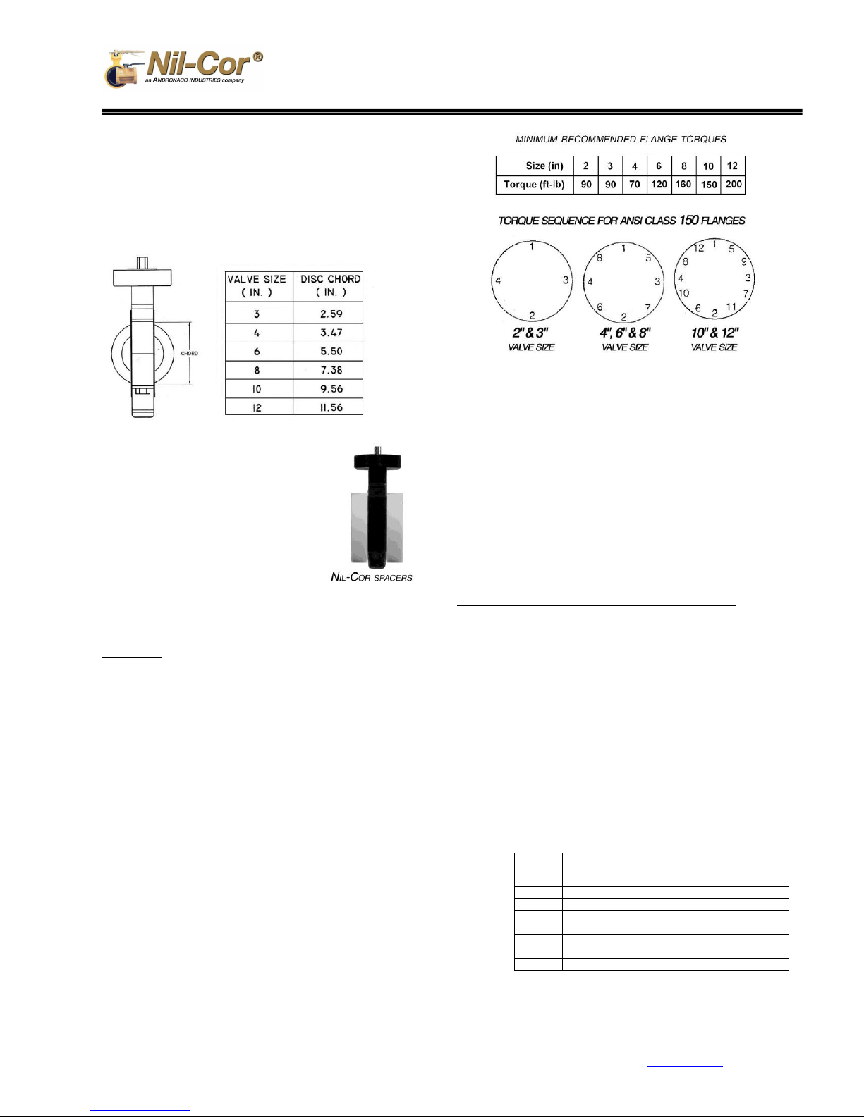
1. The 710 UHMWPE Series valve is designed to be installed
between ANSI Class 150 flanges. Contact Customer
Service for guidance with DIN PN10 & 16 flanges. Check
clearance in piping flange to permit full disc swing of the
valve. The table below lists disc swing clearance
2. If the connecting flanges have an
inside diameter that does not allow
for full swing of the disc, install
spacers with a larger I.D. These
spacers are available from Nil-Cor.
3. Important – Always use spacers
when connecting the valve directly
to fittings such as elbows, short
stack tees, etc., to permit full swing
of valve disc.
4. Ensure that adjoining flanges are clean and free of debris
that could scratch the valve seal faces.
Installation
1. Gaskets are normally not required for 710 Series
UHMWPE-Lined Valves when installed in plastic lined pipe
such as PTFE. If mating flanges are not lined with plastic, a
gasket is recommended such as Task-Line, PTFE
encapsulating a stainless steel core. Task-Line gaskets
can operate in extreme conditions and are resistant to
virtually all chemicals from –60oF to 400
o
F and they won’t
cold flow.
2. Install the valve with the disc closed. Keep the valve liner
clean during installation. Dirt or debris may scratch the liner
or disc edge, which could cause leakage.
3. Do not allow the liner to catch on the mating flange and fold
over during installation. This will cause flange leakage and
damage the valve.
4. Ensure proper alignment of valve with mating flanges so
valve disc is clear to fully rotate without contacting mating
pipe I.D.
5. Tighten the flange bolts in the proper sequence to the
values listed at right.
6. If a flange leak occurs and the bolts of the leaking side have
been properly tightened, they should not be tightened further or
permanent damage to the valve sealing face may occur.
Instead, loosen the bolts on the opposite side of the same
flange a half turn at a time and then tighten the bolts on the
leaking side by the same amount.
7. If leaking persists, remove bolts and examine sealing faces for
scratches or dents across the entire face. Any scratches which
do not exceed 20% of the valve lining thickness can be
eliminated by hand polishing with fine abrasive cloth or paper.
8. If leaks occur after system has been cycled to elevated
temperature and back to ambient temperature, re-torque bolts
to recommended torque after cool down. No further
adjustments should be necessary.
Gland Adjustment In The Event of Through-Leakage
1. The UHMWPE-lined version of the 710 Series is equipped with
hub seal adjustment glands to center the disc and compress
the liner against the disc hub.
2. With the valve closed, adjust gland nut in 1/8 -turn increments
with a torque wrench, alternating between studs. Alternate
between top and bottom glands to compress and center disc.
Increase torque up to specified settings (see Table below).
3. When testing, if seat leaks at both ends, there is not enough
compression. If seat leaks on just one side near stem, then
tighten that side and back off the other side if needed.
4. Check gland bolt torque after every step of testing. Make sure
valve is unpressurized when torque is applied.
5. Re-check torque before commissioning.
3/10/2014 4855 Broadmoor Ave. Kentwood, MI 49512 Phone: (616) 554-3100 Fax: (616) 554-5623 www.nilcor.com
Nil-Cor. LLC
2
 Loading...