

Page 1
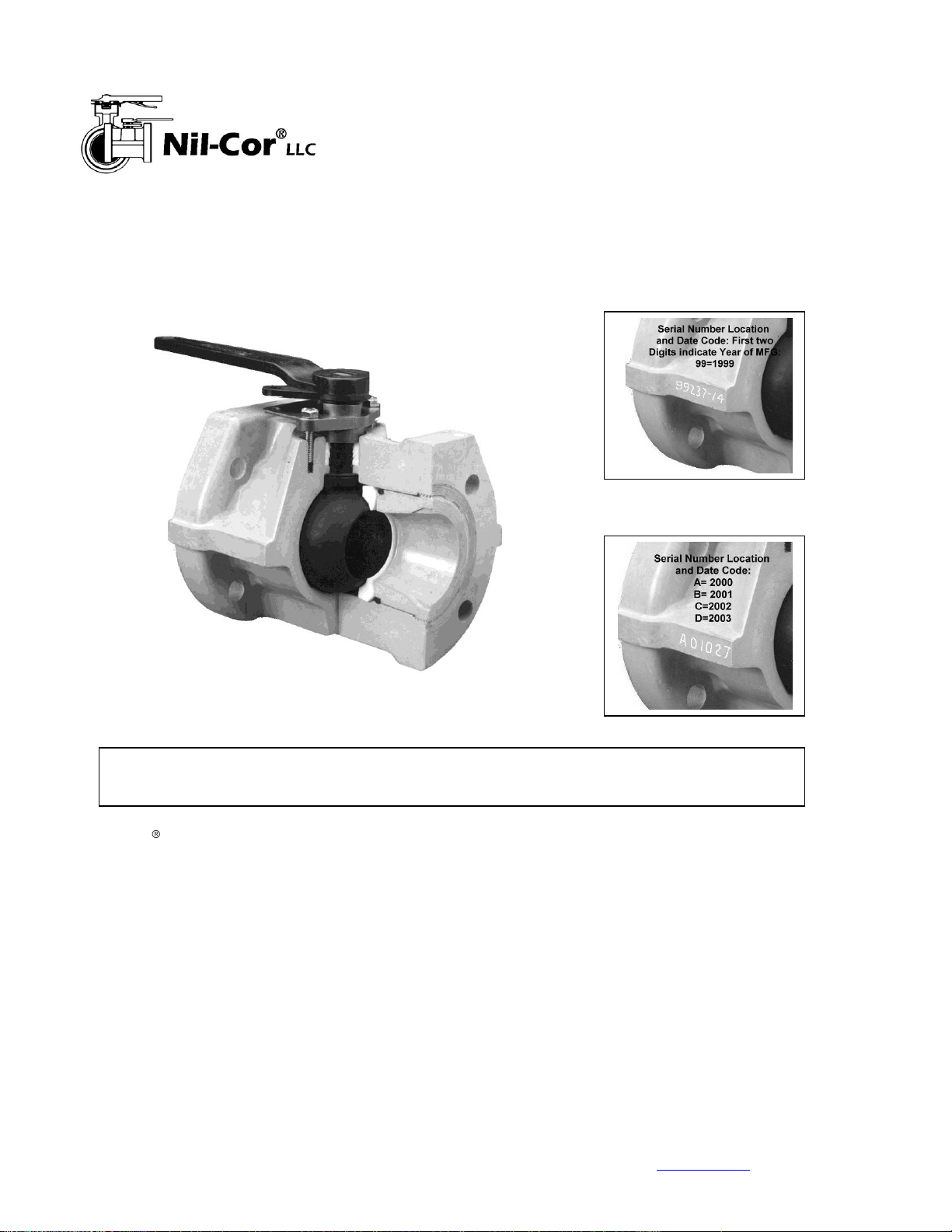
Nil-Cor ball valves have been designed for
easy installation, assembly and
maintenance. We recommend installation
in piping systems with flat-faced flanges.
When installing against raised face flanges,
spacer rings should be used to provide a
flat surface to the face of the valve flange.
A deep stuffing box around the stem holds
PTFE chevron packing, which achieves a
leak-tight seal with minimum pressure
from the gland for ease of maintenance.
With the handle off, the gland is easily
removed for access to packing. The ball
and seats are retained by a threaded body
insert that can be removed and can be
serviced by maintenance personnel who
routinely service metallic valves. In
addition, since Nil-Cor ball valves are
one-third the weight of metal valves, they
are more easily and safely installed and
maintained. All Nil-Cor valves are equipped
with lockout devices as standard.
an Andronaco industries Company
Nil-Cor Flanged Ball Valves
Installation, Maintenance and Operating Instructions
Series 300, 310, 410, 500XP and 610XP
Serial Number Date Code
Prior to Jan. 2, 2000
CAUTION: Refer to the Nil-Cor Corrosion Guide, Catalog 1000, to verify suitability
for chemical applications. Contact factory for assistance for chemicals not listed.
Location of Serial Number
and Date Code
16-May-13 1
4855 Broadmoor Ave. S.E. ● Kentwood, MI ● 49512 ● USA ● (616) 554-3100 ● www.nilcor.com
Nil-Cor, LLC, an Andronaco Industries Company
Page 2
Site Storage Precautions
1. For outside site storage ensure valves or containers are
wrapped in plastic or otherwise protected from ingress of
dust or blowing sand. Do not remove flange covers.
2. Actuated or gear operated valves should be kept dry.
3. Inside warehouse storage requires no special
protections.
Installation
1. Fluid flow may be in either direction and the valve may
be mounted in any position. When the valve terminates
a line, the insert end should be positioned toward the
flow direction (upstream side).
2. Pipe must be properly aligned and provisions made to
minimize stress from thermal expansion. Always
review pipe manufacturer's recommendations.
3. Expanded PTFE or 50 Durometer Rubber Full-Face
gaskets are recommended.
4. Flange Bolts should be evenly tightened, using a
torque wrench, in cross rotation to prevent flange
damage. Refer to the table below for proper flange
bolt torque. We recommend installation in piping
systems with flat-faced flanges.
5. When installing against raised face flanges, spacer
rings should be used to provide a flat surface to the
face of the valve flange.
6. When washers are used under the nuts on flange
studs, AN960 Aeronautics Specification washers
should be used. Optional stainless steel washer kits
meeting this specification are available from Nil-Cor.
7. After valve installation, the packing bolt torque should
be checked to ensure the stem seal. Refer to the table
below for the Packing Bolt Torque.
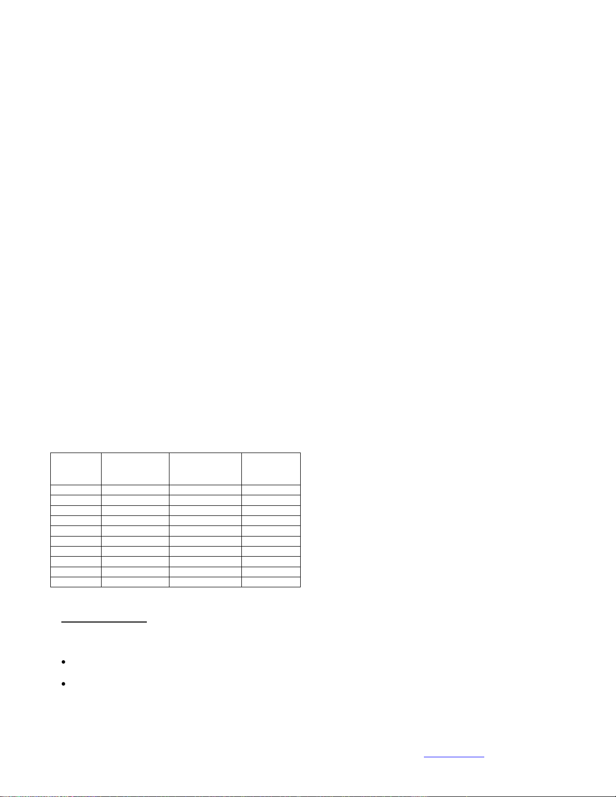
Valve Size
Flange Torque,
Min-Max (ft-lbs)
Packing Torque,
Min-Max (in-lbs)
Packing
Rings (in addition
to top and bottom
adapter rings)
1 "
20-25
20-40
2
1.5"
20-25
30-60
2
2"
20-35
35-70
2
2.5"
20-35
35-70
3
3"
25-35
50-100
3
4"
25-45
65-130
3
5"
25-40
65-130
3
6"
30-45
65-130
3
8"
40-50
65-130
3
10"
50-60
65-130
3
Safety Precautions
For your safety, it is important that these
precautions be taken before removal of the valve
from the line or before disassembly:
Wear protective clothing or equipment
appropriate for the particular fluid.
Observe the precautions and follow the
procedures in Disassembly Item 1.
Disassembly
1. Depressurize the line and valve as follows:
2. Open valve and drain the line.
3. Before removal from the line, cycle (open and close)
the valve to relieve residual pressure in the body
cavity.
4. After removal and before disassembly, cycle (open
and close) the valve several times to clear it of fluid;
then flush with water.
5. Open valve completely and remove handle.
6. Secure body in a clamping device, being careful not to
damage or crush it.
7. Remove gland bolts from the valve body.
8. Use the Insert Removal Tool, sold separately, to
unscrew body insert and remove ball, body insert
gasket, (o-ring) and the two ball seats. Take care not
to damage sealing surfaces in body or gland.
9. Carefully push valve stem down into the valve body
and withdraw it through the open end. Remove the
thrust washer from stem.
Assembly
1. Inspect and clean all parts to make sure they are free
of dust, grit or other material. New O-ring and ball
seats should be used after the valve has been used in
service and is reassembled.
2. A good lubricant compatible with the fluid service,
such as silicone grease, should be applied lightly to
seats, seal, ball, stem, and body insert threads.
3. Assemble thrust washer on stem. Carefully insert
upper end of stem into body of valve and maneuver
into opening in top of valve. Push stem upward until
thrust washer is seated.
4. While holding stem in position with one hand, slip
gland packing into cavity around upper end of stem.
See table at left for correct number of compression
rings and adapter rings. Use the gland to press
packing into place and slightly draw up the packing by
tightening the gland bolts. Assemble valve handle to
stem, insert cap screw and tighten hex nut.
5. Press one ball seat firmly into the valve body seat
cavity. When using self-relieving seats, make sure the
spherical surface of the seat faces the center of the
valve. When using seats with an o-ring backup care
should be taken to be sure that the o-ring does not fall
out or become misaligned inside the valve.
6. Rotate stem so that stem bottom is aligned axially
with the valve and ball can be fully inserted.
7. Place ball in body against seat, with ball in the closed
position. Rotate stem and ball to the open position so
that ball can not fall out.
8. Place second ball seat into the body against the ball,
and the insert O-ring in the body against the back of
the seat.
9. Screw body insert into the valve body until flange
serrations between body and insert are flush with
each other.
16-May-13 2
4855 Broadmoor Ave. S.E. ● Kentwood, MI ● 49512 ● USA ● (616) 554-3100 ● www.nilcor.com
Nil-Cor, LLC, an Andronaco Industries Company
Page 3
10. Attach handle, being sure to line up stop on the gland
with the raised stop on the handle. Carefully tighten
handle setscrew to 48 in-lbs (4 ft-lbs.) max.
11. Cycle valve open and closed to turn ball slowly with a
gentle back and forth motion, building gradually to a full
quarter turn. By rotating slowly, the seat lips will assume
a permanent seal shape against the ball and prevent
damage to the seals.
12. If maximum torque levels are exceeded, the body insert
should be installed in 2 or 3 steps as follows: Tighten the
insert until about ¼ inch still protrudes beyond the valve
face, then operate the valve on and off several times as
in step 10. Tighten the insert to about 1/32-inch from
flush and operate valve several times. Tighten insert until
flush with flange. Seat leak tests at 20 and 80 psi are
recommended.
13. Gland bolts should be tightened as indicated in the table
on page 2. If leakage should occur in service, adjustment
is made by alternately turning each packing bolt ¼ turn
until the leak stops or the maximum packing torque is
reached. (See Torque Table on preceding page.)
14. If the valve is gear-operated or automated, assemble the
mounting bracket to the actuator, but do not fully tighten
the cap screws.
15. Install the coupler into the gear or actuator drive. Be
certain that the valve and actuator are in the
corresponding position, i.e., for DA actuators, the drive
should be in the full-clockwise position with the valve
closed. For SR actuators, be certain the ball is the
position corresponding to the desired actuator air-fail
position. The axis of the actuator cylinder should align
with the axis of the valve bore.
16. Bring the actuator, bracket and coupler down onto the
valve, being certain that the coupler properly engages the
stem. Visually align coupler and stem.
17. Install and tighten the flange mounting cap screws.
Tighten the actuator mounting screws.
18. Apply air and test operation.
Maintenance
Periodic observation is recommended to ensure that the valve
is functioning well. The frequency of observation depends on
the application. Adjustment to stem gland packing should be
made periodically to compensate for wear and packing
consolidation.
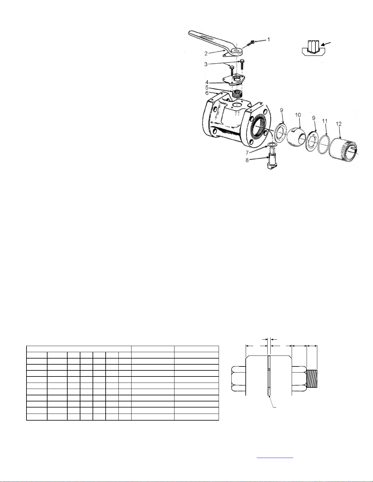
1. Setscrew: Stainless Steel.
2. Handle: VE FRP (1”-4”). All handles have locking
provision.
3. Gland Bolts: Hastelloy-C.
4. Gland: Hastelloy-C with integral locking plate.
5. Stem Packing: Chevron style PTFE.
6. Body: Solid construction of fiberglass or graphite
reinforcement and resin matrix.
7. Thrust Washer: Glass and carbon-filled PTFE.
8. Stem: Hastelloy-C metal insert with molded
composite on all wetted surfaces.
9. Seats: Virgin PTFE. Glass-filled and cavity-filler
seats available.
10. Ball: Solid construction of fiberglass or graphite
reinforcement and same resin as body.
11. Seals: PTFE-coated Viton O-ring.
12. Insert: Solid composite, same as body material.
13. Insert Removal Tool
B
ACD
Line Flange
Gasket
Nil-Cor Valve Flange
E
For Metal Flanges For FRP Flanges
SIZE A (FRP) B C D E No. Size and Length Size and Length
1" 0.875 0.13 0.88 0.5 0.2 4 1/2-13 UNC x 2.25" 1/2-13 UNC x 3.25"
1.5" 1.188 0.13 1.00 0.5 0.2 4 1/2-13 UNC x 2.5" 1/2-13 UNC x 3.5"
2" 1.188 0.13 1.00 0.63 0.2 4 5/8-11 UNC x 2.75" 5/8-11 UNC x 3.5"
2.5" 1.188 0.13 1.19 0.63 0.2 4 5/8-11 UNC x 3.0" 5/8-11 UNC x 3.5"
3" 1.188 0.13 1.36 0.63 0.2 4 5/8-11 UNC x 3.5" 5/8-11 UNC x 4.0"
4" 1.5 0.13 1.50 0.63 0.2 8 5/8-11 UNC x 3.75" 5/8-11 UNC x 4.25"
5" 1.6 0.13 1.50 0.76 0.2 8 5/8-11 UNC x 3.75" 5/8-11 UNC x 4.5"
6" 1.6 0.13 1.63 0.76 0.2 8 3/4-10 UNC x 4.0" 3/4-10 UNC x 4.75"
8" 2.06 0.13 1.75 0.76 0.2 8 3/4-10 UNC x 4.5" 3/4-10 UNC x 5.0"
10" 3.06 0.13 2.00 0.89 0.2 12 7/8-10 UNC x 4.75" 7/8-10 UNC x 6.5"
Nil-Cor Ball Valve Flange Bolt Lengths
Materials of
Construction
13
16-May-13 3
4855 Broadmoor Ave. S.E. ● Kentwood, MI ● 49512 ● USA ● (616) 554-3100 ● www.nilcor.com
Nil-Cor, LLC, an Andronaco Industries Company
Page 4
Valve
Size
A B C D E F G
H
J-
Lever
J -
Gear
HW
Dia
HW
Hgt
K
K
(QTY)
L M W
1”
5.00
.88
1.00
2.25
3.13
4.25
.88
2.50
3.08
5.60 8 8.00
.62 4 2.77
6.25
6.32
1-1/2”
6.50
1.25
1.50
3.00
3.88
5.00
1.00
3.25
3.73
6.53 8 8.92
.62 4 3.55
6.25
6.32
2”
7.00
1.50
2.00
3.66
4.75
6.00
1.00
3.50
4.18
6.71 8 9.11
.75 4 3.96
9.00
6.32
2-1/2”
7.50
1.88
2.50
4.25
5.50
7.00
1.19
3.75
5.44
8.52 8 10.92
.75 4 5.17
9.00
6.32
3”
8.00
2.31
3.00
5.00
6.00
7.50
1.36
4.00
5.58
8.52 8 10.92
.75 4 5.42
9.00
6.32
4”
9.00
3.00
4.00
6.19
7.50
9.00
1.50
4.50
7.05
9.56 8 11.96
.75 8 6.50
11.44
6.32
5”
10
3.75
5.00
7.50
8.50
10.00
1.50
5.00
7.75
11.08
12
14.46
.88 8 7.21
Note 4
7.39
6”
10.50
4.50
6.00
8.50
9.50
11.00
1.63
5.25
10.51
11.58
12
14.96
.88 8 7.91
Note 4
7.39
8”
11.50
6.00
8.00
11.25
11.75
13.50
1.75
5.75
11.77
13.00
12
17.11
.88 8 9.21
Note 4
8.77
10”
13.00
7.50
10.00
14.00
14.25
16.00
2.00
6.50
NA
13.64
18
17.50
1.00
12
11.10
NA
8.77
Actuation Mounting Dimensions
Actuation Torque (in-lbs.)
Weight (lbs.)
Valve
Size
N
P
R x (deep1)
S
T
+.000-
.010
U
+.000-
.010
V
Valve
Running
Torque
(
2)
Breakaway
Torque
(
3)
0-100 psi
Breakaway
Torque
(
3)
>100 psi
Flow
Coeff.
Max
Cv
w/o
Gear
(lbs.)
With
Gear
(lbs.)
1”
4.18
1.75
5/16 - 18 x 1/2
0.64
0.50
0.375
0.500
90
140
160
75 3 9
1-1/2”
5.62
1.75
5/16 - 18 x 1/2
1.05
0.70
0.375
0.500
125
190
230
115 6 12
2”
6.18
2.25
5/16 - 18 x 5/8
0.96
0.75
0.375
0.625
150
230
270
135 8 15
2-1/2”
6.62
2.63
3/8 - 16 x 3/4
1.67
0.75
0.50
0.88
260
400
475
250
13
20
3”
7.12
3.50
3/8 - 16 x 3/4
1.67
0.75
0.500
0.875
370
570
680
350
14
21
4”
8.00
4.00
7/16 - 14 x 7/8
2.00
1.13
0.750
1.000
680
1040
1250
540
23
30
5”
9.00
4.75
7/16 - 14 x 7/8
2.21
1.13
0.75
1.00
1000
1570
1825
1000
33
46
6”
9.00
5.25
7/16 - 14 x 1-1/8
2.41
1.13
0.750
1.000
1400
2100
2400
1240
40
53
8”
9.75
6.00
7/16 - 14 x 1-1/8
2.46
1.13
1.094
1.250
2800
4200
4800
1700
65
90
10”
11.25
7.75
½ - 13 –X 1-1/8
3.10
1.13
1.258
1.438
4100
6300
7200
2600
100
125
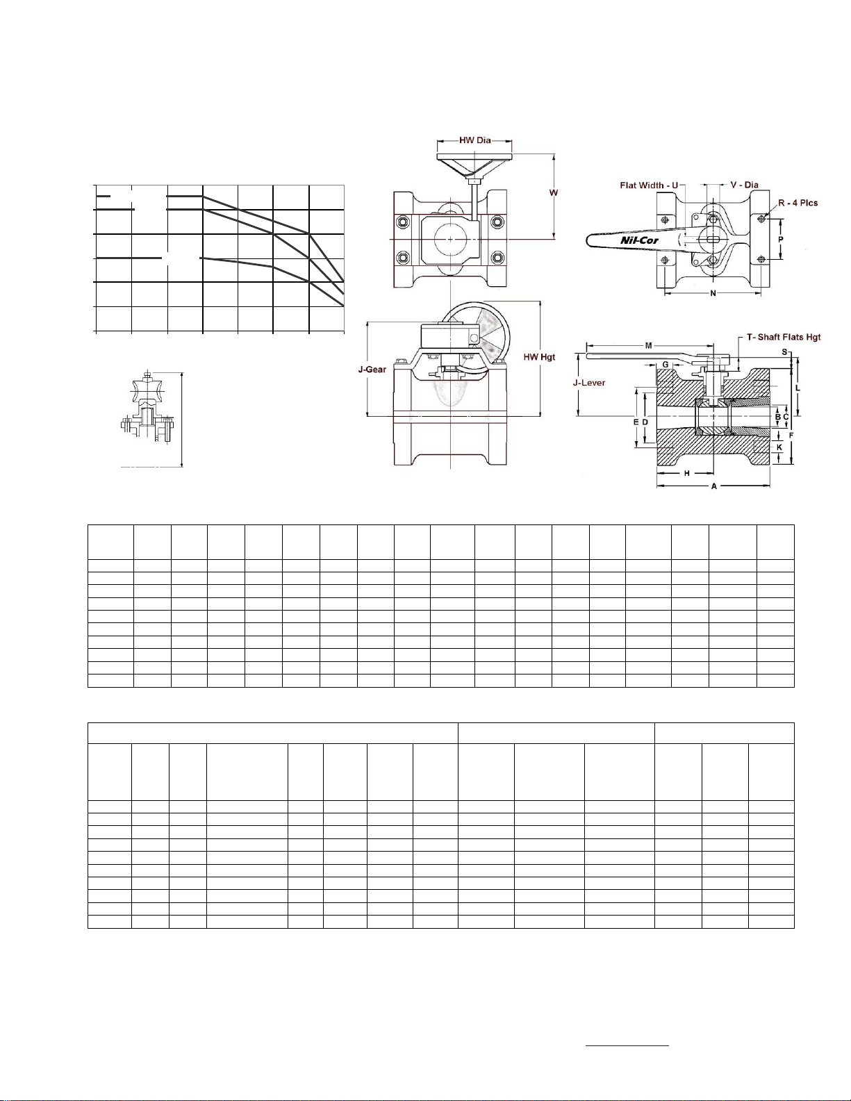
Pressure/Temperature Rating
0
50
100
150
200
250
300
-50 0 50 100 150 200 250 300
Temperature (0F)
Pressure (psig)
4” - 10”
2”, 3”
1”, 1-1//2”
J-For 6”, 8”
Handle
Adapter only
1. Minimum thread engagement required to develop design joint strength on the actuator mounting pad (composite valve body).
2. Flowing fluid, ball in motion between 0 and 90 deg.
3. Maximum breakaway torque for clean liquid service.
4. For manual 5”-8” size, use handle adapter or gear operator. Gear only on 10”
Flanged Ball Valve Dimensions
16-May-13 4
4855 Broadmoor Ave. S.E. ● Kentwood, MI ● 49512 ● USA ● (616) 554-3100 ● www.nilcor.com
Nil-Cor, LLC, an Andronaco Industries Company
 Loading...