

Page 1
Nil-Cor Flanged Ball Check Valves
Installation, Maintenance and Operating Instructions
Series 300, 310 and 410
Nil-Cor Check Valves have been designed for easy installation, assembly and
maintenance. We recommend installation in piping systems with flat face flanges. When
installing against raised face flanges, spacer rings should be used to provide a flat
surface to the face of the valve flange. The ball and seat assembly are retained by a
threaded body insert that can be removed for inspection and can be serviced by
qualified maintenance personnel.
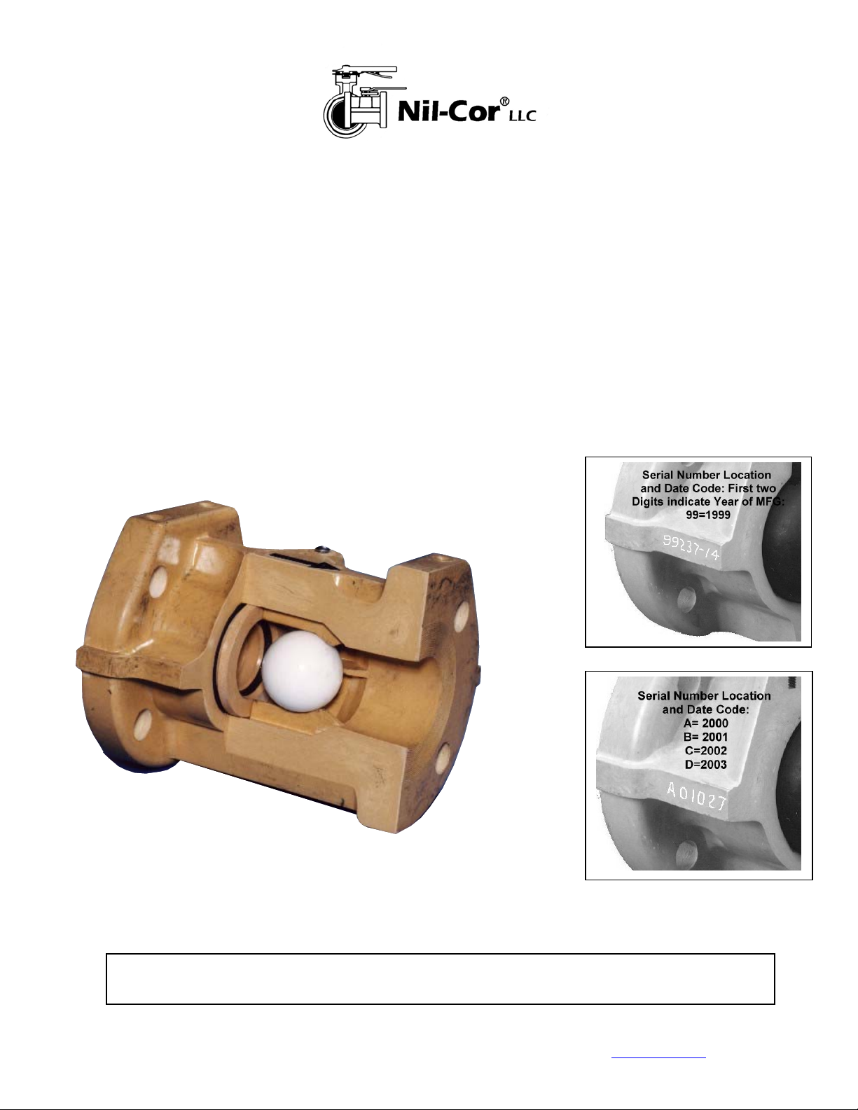
Serial Number
Date Code
Prior to Jan. 2,
2000
CAUTION: Refer to the Nil-Cor Corrosion Guide, Catalog 1000, to verify suitability for
chemical applications. Contact factoryfor assistance for chemicals not listed.
8/31/07 Pub. 410 www.nilcor.com
Serial Number
Date Code
After Jan. 2,
2000
Page 2
Installation
1) Because Nil-Cor Check Valves are unidirectional, it is important to ensure that the arrow on valve points in the direction of free flow.
2) Pipe must be properly aligned and provisions made to minimize stress from thermal expansion. Always review pipe
manufacturer’s recommendations.
3) TFE envelope or 50 Durometer Rubber gaskets are recommended.
4) Flange bolts should be evenly torqued, using a torque wrench, in cross rotation to prevent flange damage. We recommend
installation in piping systems with flat face flanges. When installing against raised face flanges, spacer rings should be
used to provide a flat surface to the face of the valve flange. Bolts should be lubricated for ease of installation.
Removal/Disassembly
For your safety, it is important that these precautions be taken before removal of the valve from the line or before disassembly:
1) Wear protective clothing or equipment appropriate for the particular fluid.
2) Observe the precautions and follow the procedures in Disassembly Item 1.
Disassembly
1) Isolate and depressurize the valve.
a. Take precaution to properly support pipeline.
b. Temporarily cap off exposed pipeline to prevent infiltration of debris.
2) Remove valve from line.
3) Use insert removal tool to remove threaded insert. Remove ball.
Assembly
1) Inspect and clean all parts to make sure they are free of dust, grit or other material. New O-ring and ball seat
should be used after the valve has been in service. Inspect seat and body retainer rings for damage. If dama ged, a complete
seat kit should be used.
2) A good lubricant compatible with fluid service should be applied lightly to seat, seal and body insert threads.
3) Replace ball.
4) Screw body insert into the valve body (flange serrations between body and insert are flush when properly installed). Tighten to torque
values in table below.
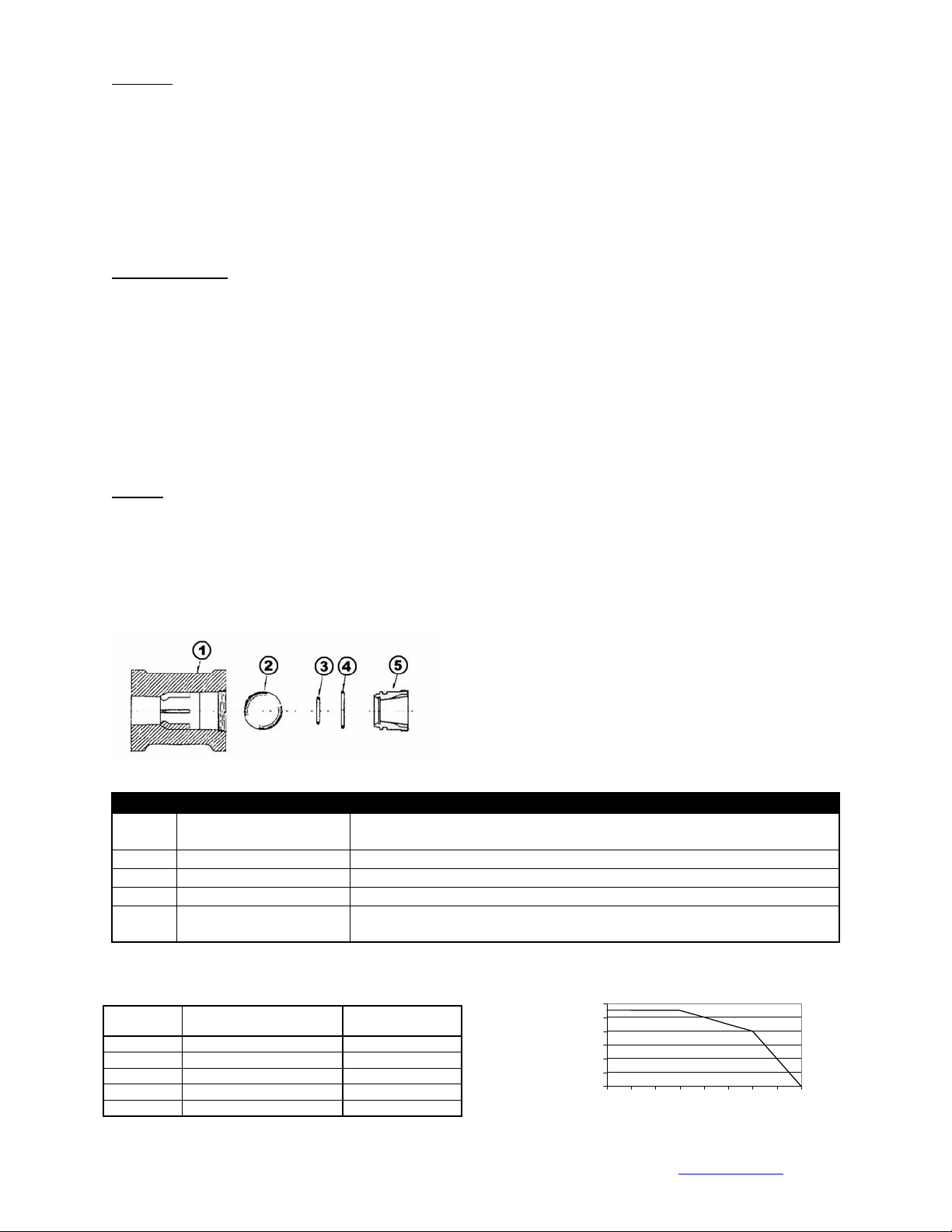
Item Description Material
1 Body Vinyl ester w/Glass Fiber or Graphite Fiber/Polysulfone w/Glass
Fiber
2 Ball Solid Virgin PTFE
3 Seat O-Ring PTFE Coated Viton
4 Body O-Ring PTFE Coated Viton
5 Body Insert Vinyl ester w/Glass Fiber or Graphite Fiber/Polysulfone w/Glass
Fiber
Valve Size Flange Bolt Torque Range
(ft. lbs.)
1” 20-30 4
1.5” 20-30 6
2” 20-45 8
3” 25-50 14
4” 25-50 20
Insert Tightening
Torque (ft. lbs.)
Pressure-Tempera ture R ating
300
250
200
150
100
50
0
Pressure (psig)
-50 0 50 100 150 200 250 300 350
1"- 4"
Temperature (oF)
8/31/07 Pub. 410 www.nilcor.com
 Loading...