

Page 1

Version: 6.00, 12-03-2012
Software-version: 1.38
VPL 15
VPL 15 Top
VPL 25
Installation instruction
CTS 600 by Nilan
Page 2

Table of contents
Table of contents ............................................................................................................................ 2
Figure table .................................................................................................................................... 2
Introduction ..................................................................................................................................... 3
Power supply .................................................................................................................................. 4
Assembly of VPL 15/15T/25 ........................................................................................................... 5
Condensation drain / water seal ..................................................................................................... 6
Ducting ........................................................................................................................................... 7
Heating surface, water .................................................................................................................... 8
Heating surface, electrical (retrofitting) ......................................................................................... 10
Starting and set up of the CTS 600 control .................................................................................... 11
Starting ..................................................................................................................................... 11
Set up of the CTS 600 control ................................................................................................... 11
Activating the service menu ...................................................................................................... 12
Heating surface ......................................................................................................................... 13
Air exchange ............................................................................................................................. 14
Defrost ...................................................................................................................................... 15
Temp. control ............................................................................................................................ 16
Inlet control ............................................................................................................................... 17
Room control ............................................................................................................................ 18
Restart ...................................................................................................................................... 19
Preset ....................................................................................................................................... 20
Manual ...................................................................................................................................... 21
System dimension ........................................................................................................................ 22
Accessories / spare parts ............................................................................................................. 23
Figure table
Figure 1: CTS 600 control ............................................................................................................... 4
Figure 2: Mounting the VPL-Unit ..................................................................................................... 5
Figure 3: Condensation drain / water seal....................................................................................... 6
Figure 4: Insulation of ducting ......................................................................................................... 7
Figure 5: Connecting the heating surface, suggestion .................................................................... 8
Figure 6: CTS 600 control ............................................................................................................. 11
Figure 7: Headlines in the servicemenu ........................................................................................ 12
Figure 8: The "Heating surface" menu .......................................................................................... 13
Figure 9: The "Air exchange" menu ................................ .............................................................. 14
Figure 10: The "Defrost" menu ..................................................................................................... 15
Figure 11: The "Temp. control" menu ........................................................................................... 16
Figure 12: The "Inlet control" menu............................................................................................... 17
Figure 13: The "Room control" menu ............................................................................................ 18
Figure 14: The "Restart" menu ..................................................................................................... 19
Figure 15: The "Preset" menu ....................................................................................................... 20
Figure 16: The "Manual" menu ..................................................................................................... 21
Figure 17: System dimension ....................................................................................................... 22
Page 3

This document may be subject to change Side 3 of 23
Introduction
Please control that the following documents have been delivered together with the unit:
- Directions for assembly & use (this document)
- CTS 600 directions
- Electrical chart
Should you have any questions on how to operate the system, contact your nearest Nilan dealer,
who you can find at www.nilan.dk/dealers
VPL 15/15T/25 is a ventilation unit with heat recovery. The unit can yield up to 325/700m3/h at
100Pa external back pressure.
The unit can be equipped with different accessories e.g. hygrostat and filter box with pollen filter.
Operating the unit is done with the CTS 600 control. The control has many functions such as menu
based attendance, week programme, time controlled filter guard and adjustment of the velocity of
the ventilator. (Directions for the CTS 600 control is described in another document delivered with
the unit.)
For accessories see page 23.
We recommend that the system as well as the installation are adjusted/checked to ensure a healthy indoor climate and optimal operation.
Page 4
This document may be subject to change Side 4 of 23
Power supply
Power supply including safety switch must be installed by an authorized electrician.
The VPL 15/15T/25 unit must be connected according to the attached electrical chart.
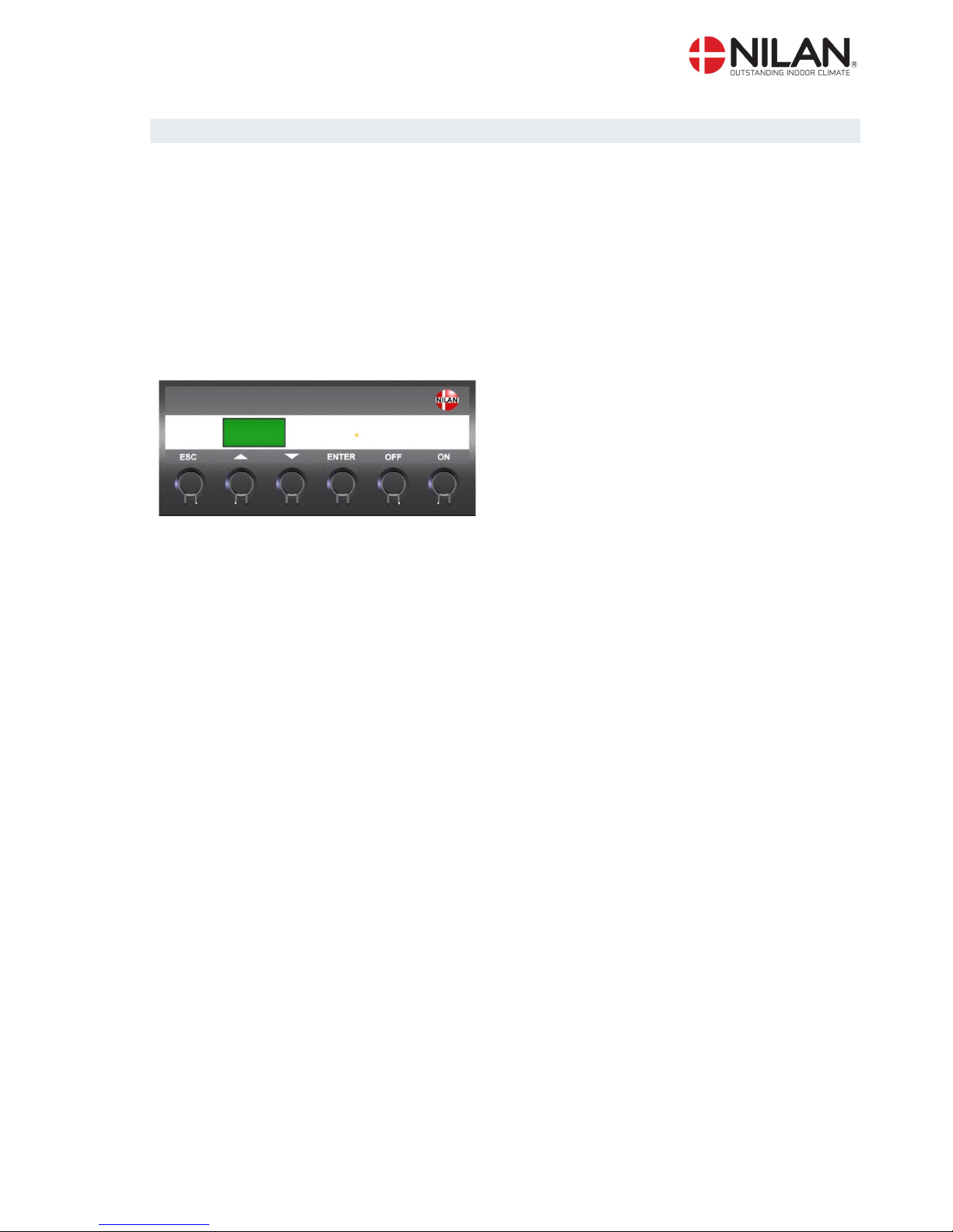
The unit is delivered with 1m test cable for the CTS 600 panel. The panel should be connected to
the CTS 600 control in the unit with cable type 2x2x0.25mm2 twisted in pairs. (Maximum length
50m).
The CTS 600 panel must be placed dry and frost-proof. The panels’ integrated feeler prevents further cooling of the building if the primary heat-supply stops by stopping the ventilation if the panel
feeler gets below a specific value. (Factory setting is 10°C; the value can be set from 1°C to 20°C.)
Figure 1: CTS 600 control
If a water post-heating element is installed, the control valve and circulation pump must be electronically connected as described in the provided wiring diagrams.
Page 5
This document may be subject to change Side 5 of 23
Assembly of VPL 15/15T/25
When mounting the VPL-unit future service and maintenance should be considered.
There is required a minimum of open space in front and behind the unit of 600mm .
The system’s connection pieces and the pipes are connected with a flexible transition (flex
pipes/sound flex pipes or the like).
The system must be level due to the condense outlet. The condense outlet requires a clearance
height of minimum 80-105 mm under the outlet connection piece.
It is not necessary to re-insulate the system as it is delivered with a 20mm standard insulation.
The system is low-noise and low-vibration. However, potential vibrations spreading from the sys-
tem to the individual building parts must be taken into account. We recommend a minimum
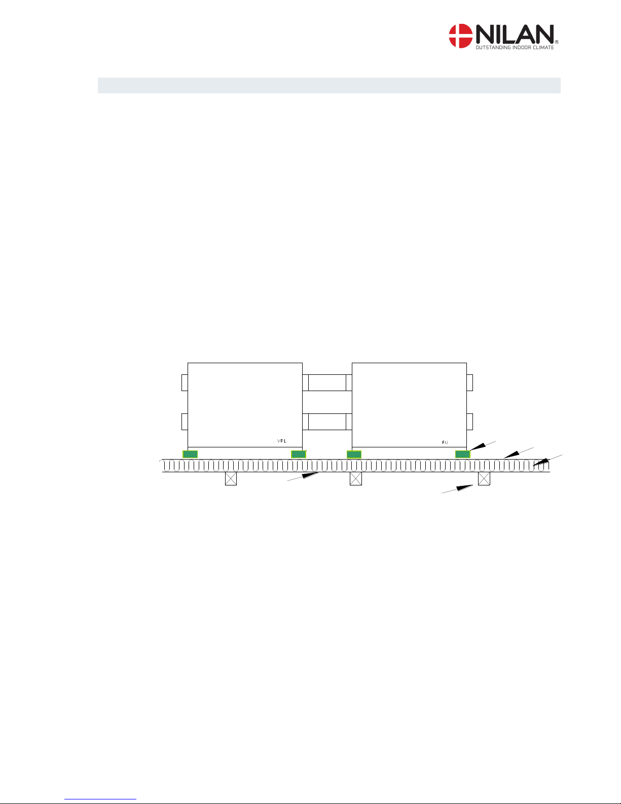
distance of 30 mm from building parts and other fixtures. To detach the system from the floor, we
recommend that the system is placed on vibration absorbers as illustrated in figure 2 (See Accessories)
2 1 2
3
4
1: Vibration absorbers.
2: 22mm plywood/ chip board
3: Firm insulating batts
4: Wooden beam
Figure 2: Mounting the VPL-Unit
Page 6
This document may be subject to change Side 6 of 23
Condensation drain / water seal
The VPL unit is delivered with a 20mm condensation drain. (PVC, GF-fittings). The drain is placed
under the discharge.
The condensation drain should be carried with an even inclination of at least 1 cm per
meter, frost-proof to the nearest outlet. The overflow from the safety valve should also be
carried to the nearest outlet.
To avoid frost problems it can be necessary to supply the condensation drain with a
heating cable. It is the plumbers’ responsibility to secure the drain.
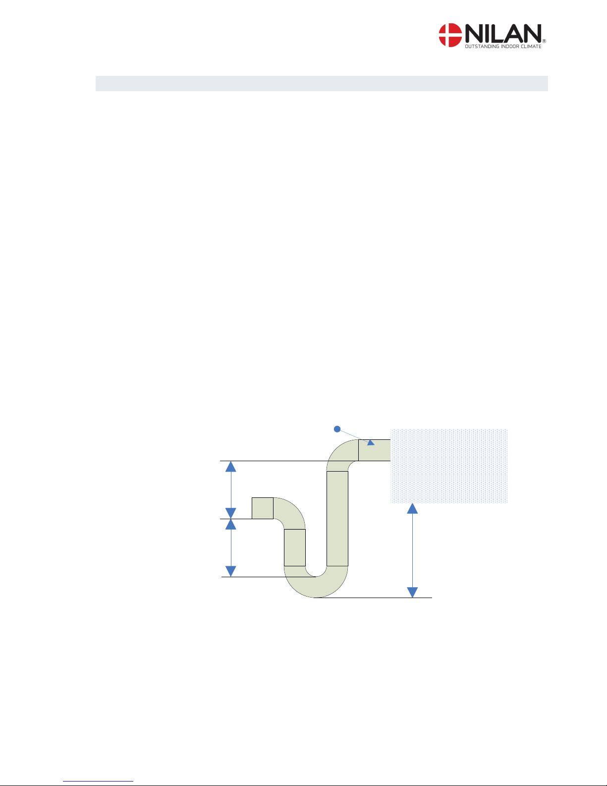
When the system is running, there can be a vacuum of up to 500Pa (corresponding to 50mm water
column) in the outlet. For this reason, the difference in height in the water seal must be minimum
50mm. This means that the first bend of the water seal must be at least twice as long in order for
the system to be able to dispose of the condense water (see figure 3).
The condensation drain must be airproof from the unit to the water seal in order for the condensation water to be let away from the unit. If the condensation drain is not airproof false air will be
sucked in to the unit and the water will stay inside the unit.
The water seal can dry out and avoid the water from running out of the unit. Therefore the water
seal should be tested regularly and refilled with water if necessary. An elevated height of the water
seal will reduce the need for refilling with water.
min. 112,5 mm
min. 50 mm.
min. 50 mm.
Ø20 mm drain
VPL
Figure 3: Condensation drain / water seal
The water seal should be tested as described below. (the unit must be connected to the
ducting and the front door should be closed):
The condensation tray is filled with water and the unit is started at the highest ventilation
step. The unit should run for a couple of minutes. Check that the condensation tray is
empty when the test is finished.
Page 7
This document may be subject to change Side 7 of 23
Ducting
We recommend that there are used ducts and fittings with rubber packing that meet sealing class
B and that the connections between the unit and the ducting are made with 1 metre sound absorbing flexible transitions as regards sound reduction.
The ducts should be shortened with a hacksaw or an angle grinder and laid out according to the
working drawing. The ducts are typically laid out on the main beam of the truss frame and are secured with hole belts or they are being hanged in assembly belts. Please avoid any unnecessary
area reductions and breaks of the ducting.
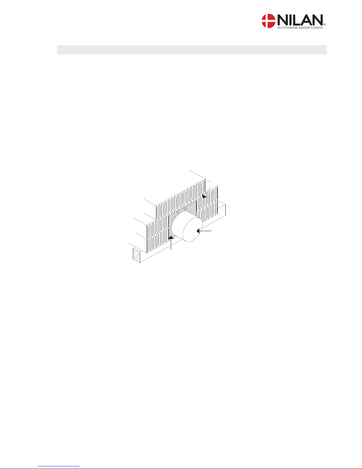
The ducts should be insulated – in some cases with the ordinary attic-insulation. All ducts should
be insulated with 100mm mineral wool to avoid heat loss and condensation. This also applies for
flexible transitions. It is recommended that the insulation is carried out with 2 layers of 50mm. If the
ducts are laid out in an unheated room it will cause condensation problems if the unit are turned off
for a longer period of time as the hot air from the heated room will rise to the ducts and cause condensation which can cause damp problems.
Figure 4: Insulation of ducting
The discharge duct is leading the exhaust air away either above the roof or through the outer wall.
It is important that the roof cowl has at least the same open space as the duct leading to the roof
cowl. A reduction at this place will cause an unnecessary pressure drop which can lead to a reduced ventilation output.
The holes for the inlet- and exhaust valves should be cut according to the mounting-frame for the
prescribed valve. The frame for the valve must be secured with screws before placing the valve in
the frame. The valves are placed in accordance with the size, construction and use of the room. As
an example we would not recommend placing an inlet valve just above people with sedentary work
because the inlet air in some cases would be experienced as a draught.
Granulate
Duct
Loft insulationmaterial
Page 8
This document may be subject to change Side 8 of 23
Heating surface, water
Connecting the heating surface must be done by an authorized plumber.
If the unit is placed outside or in a cold location the installation must frost secured.
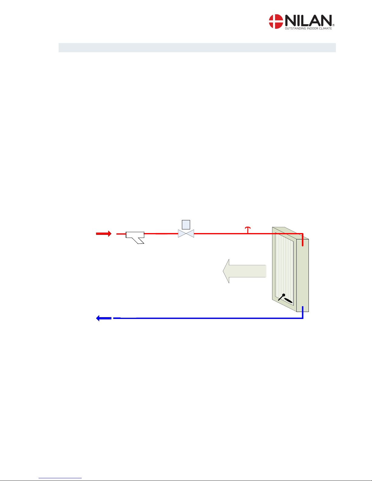
The heating unit is delivered as accessory and consists of: electrical box with LMC200-PCB, heating surface with temperature sensor T9 and frost-protection B3, actuator and regulating valve.
The heating surface is to be installed in the inlet ducting just after the VPL unit. The heating surface must also be activated in the CTS 600 control as described on page 13.
The mixing loop can be constructed as suggested below.
The heating surface should be connected, scavenged and checked for any leakages before start-
ing the unit.
The dirt-catcher should be checked and cleaned after a thoroughly flushing of the system.
Air flow
Flow
Return
B3
T9
2
1
M
Heating surface
3
Note that the temperature sensor T9 and frost-protection B3 is placed at the heated side of the heating
surface close to the return connection. See electrical chart.
1:
Actuator and regulating valve:
Danfoss AME 140/24V 0-10V signal, 2-way valve VZ2 Kv 0,4, (Nilan delivery) Kvs-value must be
checked in accordance with supply.
Differential pressure: 0,1 – 0,6bar
There is calculated with a cooling of 20°C over the heating surface at a flow of 60°C.
2:
Scavenging (not Nilan delivery)
3:
Dirt-catcher (not Nilan delivery)
Figure 5: Connecting the heating surface, suggestion
Page 9

This document may be subject to change Side 9 of 23
IMPORTANT regarding Danfoss Actuator type AME 140:
Re-installing the actuator must be done as described below:
1. Disconnect the power supply and remove the cover of the actuator.
2. Liberate the gear by pressing down the button as the spindle is turned up (counter clockwise)
3. Re-install the actuator and turn on power.
4. DIP-switch nr. 1 should be moved to ON and then to OFF.
5. The actuator is automatically calibrating for up to 6 minutes.
(The LED is flashing when calibrating and is lit constantly when finished).
6. Re-install the cover of the actuator.
Permissible ambient temperature for Danfoss Actuator type AME 140/24 V is 0 ° C to 55 ° C.
Actuators are IP42 and therefore not suitable for mounting in the open..
Electrical box with LMC200 PCB for heating surface:
Power supply must be installed by an authorized electrician.
The electrical box should be installed closed to the inlet branch of the unit.
230V power supply should be installed together with the ventilation unit.
T9, temperature sensor of the heating surface, should be installed in the electrical box.
T7, temperatur sensor of the inlet, should be let 3cm. into the inlet duct approximately 0,5m
away from the ventilation unit.
Danfoss Actuator should be connected to the clamps in the electrical box.
B3 frost-protection should be connected to the CTS 600 PCB in the ventilation unit.
See electrical chart.
Page 10

This document may be subject to change Side 10 of 23
Heating surface, electrical (retrofitting)
Electrical heating surface should be installed in the ducting (Ø160/Ø200). When retrofitting an electrical heating surface it should be activated in the 600 control panel as described on page 15.
Power supply must be installed by an authorized electrician.
See electrical chart for the ventilation unit and electrical chart for LMC200 PCB A - H.
Page 11
This document may be subject to change Side 11 of 23
Starting and set up of the CTS 600 control
Starting
Before starting the VPL please check all functions as cooling, heating and heating surface if installed.
Set up of the CTS 600 control
In this passage we will go through the service menu of the CTS 600 control. For daily use of the
CTS 600 control please see the CTS 600 directions. (delivered together with the VPL).
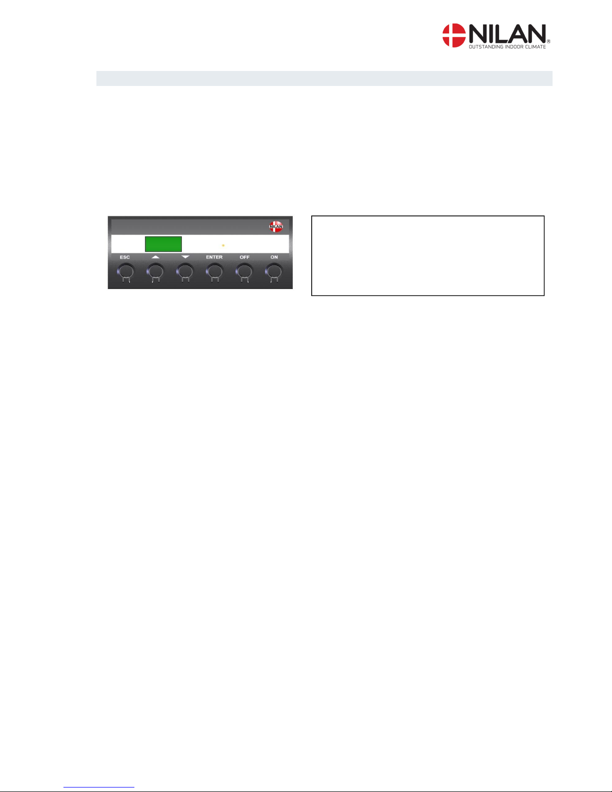
Us e of t he CTS 600 panel :
- pr ess ESC t o go one st ep back i n t he me nu
- pr ess qpt o move up or down i n a me nu or t o
adj ust an act i vat ed menu
- pr ess ENTER t o a ct i va t e a menu
- pr ess ENTER t o c onf i r m a me nu
- pr ess OFF t o t ur n of f t he uni t
- pr ess ON t o t ur n t he uni t on
Figure 6: CTS 600 control
Page 12
This document may be subject to change Side 12 of 23
Activating the service menu
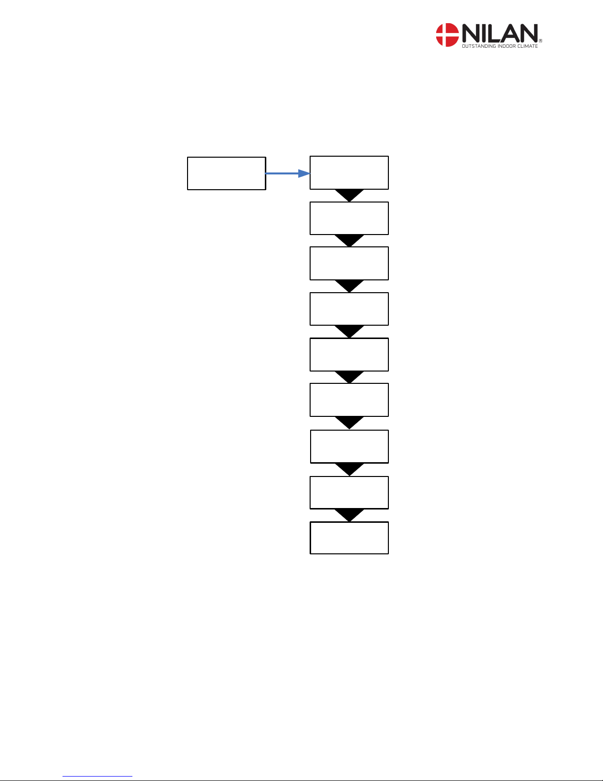
Press q and ENTER at the same time for 10 seconds. The service menu is now available. Press
q multiple times until the panel shows SERVICE. Press ENTER to enter the service menu. It is
now possible to move around in the menu by using pq. The headlines of the service menu are
shown below:
HEATING
SURFACE
AIR
EXCHANGE
DEFROST
TEMP.
CONTROL
INLET
CONTROL
ROOM
CONTROL
PRESET
OFF
MANUEL
OFF
SERVICE
ENTER
Se side 21
Se side 20
Se side 18
Se side 17
Se side 16
Se side 15
Se side 14
Se side 13
RESTART
OFF
Se side 19
Figure 7: Headlines in the servicemenu
Page 13
This document may be subject to change Side 13 of 23
Heating surface
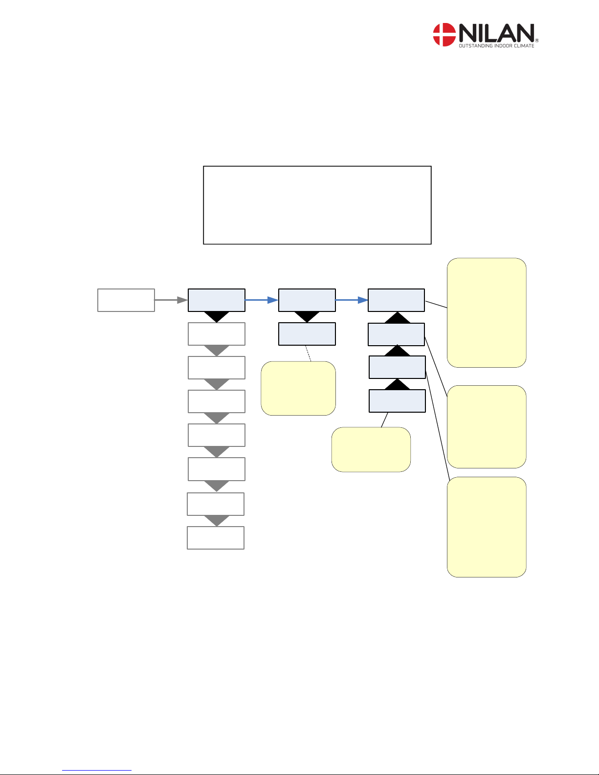
The unit can be equipped with a heating surface.
It is possible to retrofit a heating surface. The surface must be activated in the CTS 600 control in
order to function together with the unit and for the frost-protection to be active.
When installing a heating surface T7 is the temperature sensor in the inlet.
Us e of t he CTS 600 panel :
- pr ess ESC t o go one st ep back i n t he me nu
- pr ess qpt o move up or down i n a me nu or t o
adj ust an act i vat ed menu
- pr ess ENTER t o a ct i va t e a menu
- pr ess ENTER t o c onf i r m a me nu
- pr ess OFF t o t ur n of f t he uni t
- pr ess ON t o t ur n t he uni t on
HEATING
SURFACE
SELECT
”OFF”
SELECT
WATERSUP
DELAY
0 MIN
SELECT
”EB SUP”
SELECT
”EL SUP”
SERVICE
ENTER ENTERENTER
AIR
EXCHANGE
DEFROST
INLET
CONTROL
TEMP.
CONTROL
MANUEL
OFF
RESTART
OFF
ROOM
KONTROL
Should be chosen
when installing a
heating surface for
water.
Controlled via 0 -10
V signal
LMC-200 PCB
should be installed.
Otherwise ”Alarm
90 slave I/O”
occurs.
Should be chosen
when installing an
electrical heating
surface, binary
controlled
(connection of steps
via relays on CTS
600 PCB)
Should be chosen
when installing an
electrical heating
surface, controlled
via 0-10 V signal
LMC-200 PCB
should be installed.
Otherwise ”Alarm
90 slave I/O”
occurs.
Indstilling ”OFF”
vælges ved anlæg
uden
eftervarmeflade
Delay between
start of ventilators
and heating
surface (0 – 60
minutes)
SELECT
”WATERSUP”
Figure 8: The "Heating surface" menu
Page 14
This document may be subject to change Side 14 of 23
Air exchange
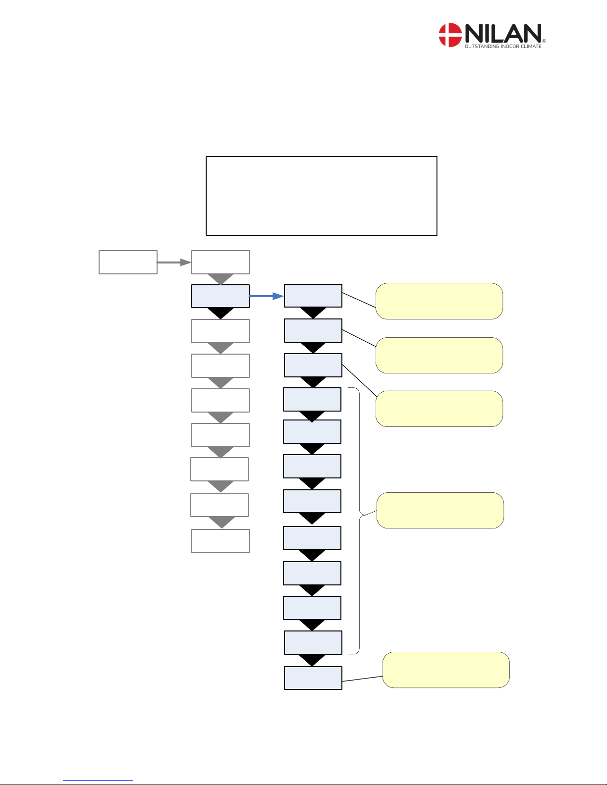
In the ”Air exchange” menu it is possible to adjust 4 steps of ventilation speed (air volume). Inlet
and exhaust is to be adjusted individually at each level.
The inlet speed can be adjusted to a minimum and the exhaust can be adjusted to both a maximum and a minimum.
It is possible to delay the starting of the fan in order to give time to the register to open.
Us e of t he CTS 600 panel :
- pr ess ESC t o go one st ep back i n t he me nu
- pr ess qpt o move up or down i n a me nu or t o
adj ust an act i vat ed menu
- pr ess ENTER t o a ct i va t e a menu
- pr ess ENTER t o c onf i r m a me nu
- pr ess OFF t o t ur n of f t he uni t
- pr ess ON t o t ur n t he uni t on
.
AIR
EXCHANGE
ENTER
SERVICE
ENTER
DEFROST
INLET
CONTROL
TEMP.
CONTROL
PRESET
OFF
RESTART
OFF
ROOM
CONTROL
HOTWATER
The lowest permissible
ventilation step for fresh air/inlet
(0-2)
The lowest permissible
ventilation step for outlet/exhaust
(1-2)
INLET
MIN 0
EXHAUST
MIN 1
EXHAUST
MAX 4
The highest permissible
ventilation step for outlet/exhaust
(3-4)
INLET
23%
INLET
>2< 40%
INLET
>3< 65%
EXHAUST
>1< 25%
EXHAUST
>3< 70%
EXHAUST
>4< 100%
INLET
>4< 100%
EXHAUST
>2< 45%
Each ventilation step can be set
as a percentage of maximum fan
speed.
MANUAL
OFF
>1<
DELAY
2 MIN
Delayed start of vent. This gives
the valve time to open fully
before the vents start (0-4 min.)
Figure 9: The "Air exchange" menu
Page 15
This document may be subject to change Side 15 of 23
Defrost
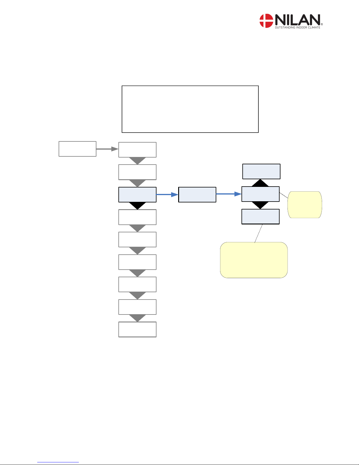
In the ”Defrost” menu it is possible to chose how the unit should perform during defrosting of the
evaporator in the exhaust.
” ” indicates that the menu point flashes and can be set to another value
Us e of t he CTS 600 panel :
- pr ess ESC t o go one st ep back i n t he me nu
- pr ess qpt o move up or down i n a me nu or t o
adj ust an act i vat ed menu
- pr ess ENTER t o a ct i va t e a menu
- pr ess ENTER t o c onf i r m a me nu
- pr ess OFF t o t ur n of f t he uni t
- pr ess ON t o t ur n t he uni t on
Airflow stopped during
defrosting (should be used
when exhaust air
temperature is less than
10°C).
DEFROST
AIR EXCH
USER
ENTER
HEATING
AIR
EXCHANGE
INLET
CONTROL
SERVICE
ENTER
TEMP.
CONTROL
RESTART
OFF
MANUAL
OFF
PRESET
OFF
ROOM
CONTROL
Constant
air flow
during
defrosting.
ENTER
AIR EXCH
”USER”
AIR EXCH
”OFF”
AIR EXCH
”LOW”
SURFACE
Figure 10: The "Defrost" menu
Page 16
This document may be subject to change Side 16 of 23
Temp. control
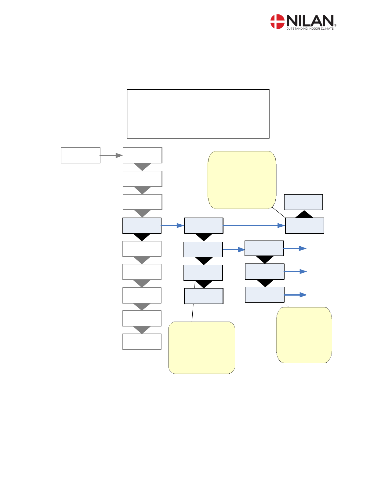
In the ”Temp. control” menu it is possible to chose a room temperature where the unit stops in
order to avoid further cooling of the building if the primary heating shuts down.
” ” indicates that the menu point flashes and can be set to another value
Us e of t he CTS 600 panel :
- pr ess ESC t o go one st ep back i n t he me nu
- pr ess qpt o move up or down i n a me nu or t o
adj ust an act i vat ed menu
- pr ess ENTER t o a ct i va t e a menu
- pr ess ENTER t o c onf i r m a me nu
- pr ess OFF t o t ur n of f t he uni t
- pr ess ON t o t ur n t he uni t on
HEATING
SURFACE
Indicates which sensor
that needs to be the
controlling one.
PANEL T15 (Panel
sensor).
EXTERNAL T10 (to be
installed in representative
extraction fitting).
TEMP.
CONTROL
SENSOR
PANEL
SENSOR
”PANEL”
PRIORITY
”HP”
PRIORITY
”OFF”
ENTER ENTER
ENTER
ROOM
LOW 10°C
PRIORITY
HP+EXT
AIR
EXCHANGE
DEFROST
INLET
CONTROL
SERVICE
ENTER
RESTART
OFF
MANUAL
OFF
PRESET
OFF
ROOM
CONTROL
The unit stops at this
room temperature (120°C) - - means that the
function is unactive.
- - should be chosen if
the panel is placed in a
cold environment.
OFF: ventilation
without heatpump
HP: ventilation only
with heatpump activ
ENTER
ENTER
EXTERNAL
-1 °C
SENSOR
”EXTERNAL”
PRIORITY
”HP+EXT”
ENTER
HP+EXT: ventilation
with heatpump and
heating surface activ
Figure 11: The "Temp. control" menu
Page 17
This document may be subject to change Side 17 of 23
Inlet control
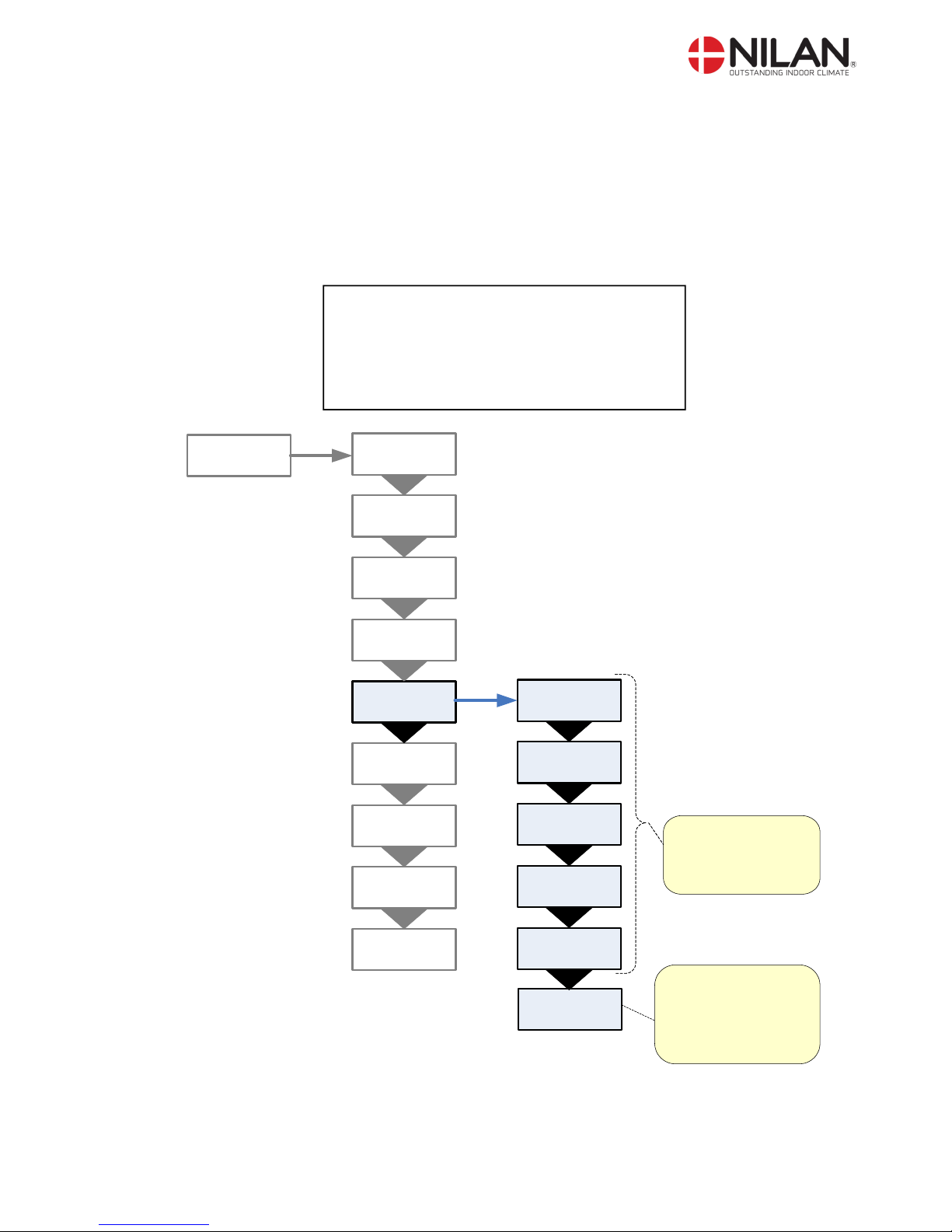
In the ”Inlet control” menu it is possible to adjust the period of time before restart of the compressor.
The ”Inlet control” menu should only be adjusted by persons with knowledge of control
engineering. (To restore factory settings, see page 19)
” ” indicates that the menu point flashes and can be set to another value
Us e of t he CTS 600 panel :
- pr ess ESC t o go one st ep back i n t he me nu
- pr ess qpt o move up or down i n a me nu or t o
adj ust an act i vat ed menu
- pr ess ENTER t o a ct i va t e a menu
- pr ess ENTER t o c onf i r m a me nu
- pr ess OFF t o t ur n of f t he uni t
- pr ess ON t o t ur n t he uni t on
TEMP.
CONTROL
HOTWATER
AIR
EXCHANGE
DEFROST
SERVICE
ENTER
RESTART
OFF
MANUAL
OFF
PRESET
OFF
ROOM
CONTROL
INLET
CONTROL
HEATPUMP
RST ”6m”
The minimum length of
time (in minutes) the
compressor must be
stopped before
restarting.
GAIN
7.0%/°
INTEGRAL
120s
N-ZONE
2.0°C
TMP- RAMP
0.10°/s
KAP- RAMP
0.5%/s
ENTER
The menu options are
only accessible when
the system has a postheating element
Figure 12: The "Inlet control" menu
Page 18
This document may be subject to change Side 18 of 23
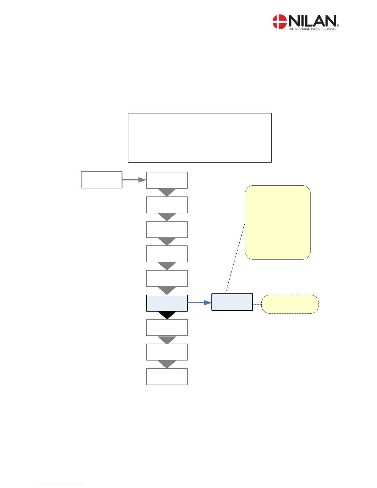
Room control
In the ”Room control” menu it is possible to adjust the regulator for controlling the room temperature.
The ”Room control” menu should only be adjusted by persons with knowledge of control
engineering.
” ” indicates that the menu point flashes and can be set to another value
Us e of t he CTS 600 panel :
- pr ess ESC t o go one st ep back i n t he me nu
- pr ess qpt o move up or down i n a me nu or t o
adj ust an act i vat ed menu
- pr ess ENTER t o a ct i va t e a menu
- pr ess ENTER t o c onf i r m a me nu
- pr ess OFF t o t ur n of f t he uni t
- pr ess ON t o t ur n t he uni t on
ROOM
CONTROL
TEMP.
CONTROL
HEATING
AIR
EXCHANGE
DEFROST
INLET
CONTROL
SERVICE
ENTER
RESTART
OFF
MANUAL
OFF
PRESET
OFF
ENTER N-ZONE
2.0°C
SURFACE
Heat demand:
Neutral Zone for start
and stop of the
evaporator:
Desired room
temperature (21°C) +
N-ZONE (2°C) = 20°C
for start of the
evaporator, 22°C for
stop of the evaporator
Can be set from
0,5-10°C.
Figure 13: The "Room control" menu
Page 19
This document may be subject to change Side 19 of 23
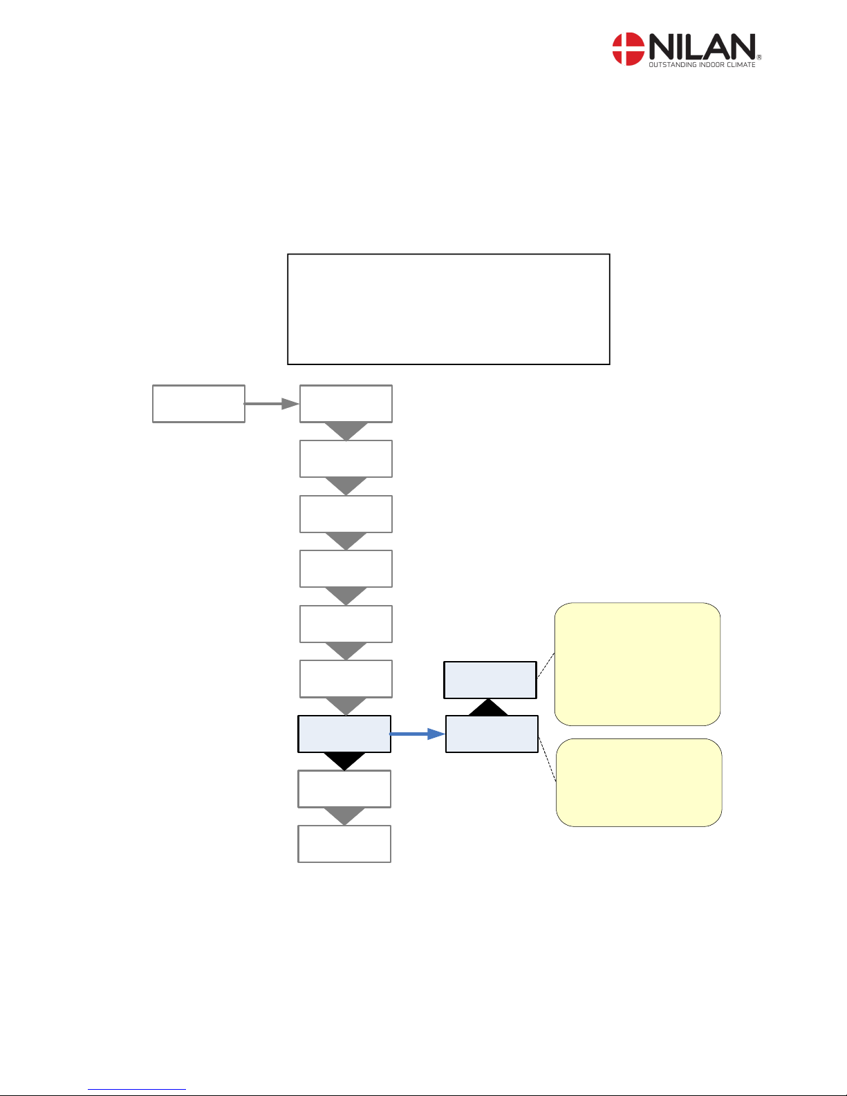
Restart
The ”Restart” menu enables you to set the unit to automatically restart in connection with highpressure/low-pressure alarms.
” ” indicates that the menu point flashes and can be set to another value
The setting HP/LP in the Restart menu may not be used under normal conditions.
Us e of t he CTS 600 panel :
- pr ess ESC t o go one st ep back i n t he me nu
- pr ess qpt o move up or down i n a me nu or t o
adj ust an act i vat ed menu
- pr ess ENTER t o a ct i va t e a menu
- pr ess ENTER t o c onf i r m a me nu
- pr ess OFF t o t ur n of f t he uni t
- pr ess ON t o t ur n t he uni t on
HEATING
SURFACE
This function may not be
used under normal
conditions. (the function
indicates that the unit
should restart automatcally
when high-pressure/lowpressure alarms occur.)
AIR
EXCHANGE
DEFROST
TEMP.
CONTROL
ROOM
CONTROL
SERVICE
ENTER
INLET
CONTROL
MANUAL
OFF
PRESET
OFF
RESTART
OFF
ENTER
RESTART
”HP/LP”
RESTART
OFF
Indicates that the unit
should not restart
automatically when high-
pressure/low-pressure
alarms occur.
Figure 14: The "Restart" menu
Page 20
This document may be subject to change Side 20 of 23
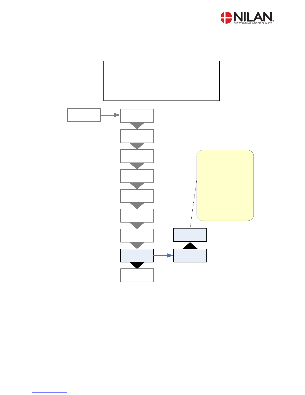
Preset
” ” indicates that the menu point flashes and can be set to another value
Us e of t he CTS 600 panel :
- pr ess ESC t o go one st ep back i n t he me nu
- pr ess qpt o move up or down i n a me nu or t o
adj ust an act i vat ed menu
- pr ess ENTER t o a ct i va t e a menu
- pr ess ENTER t o c onf i r m a me nu
- pr ess OFF t o t ur n of f t he uni t
- pr ess ON t o t ur n t he uni t on
HEATING
AIR
EXCHANGE
DEFROST
INLET
CONTROL
SERVICE
ENTER
TEMP.
CONTROL
MANUAL
OFF
ROOM
CONTROL
RESTART
OFF
PRESET
OFF
ENTER
PRESET
”OFF”
PRESET
”STANDARD”
When ”standard” is
chosen all factory
settings are reset. An
eventual supplementary
heating surface must be
re-activated.
A heating surface is NOT
frost-protected until it is
correctly installed and
activated in the service
menu.
SURFACE
Figure 15: The "Preset" menu
Page 21
This document may be subject to change Side 21 of 23
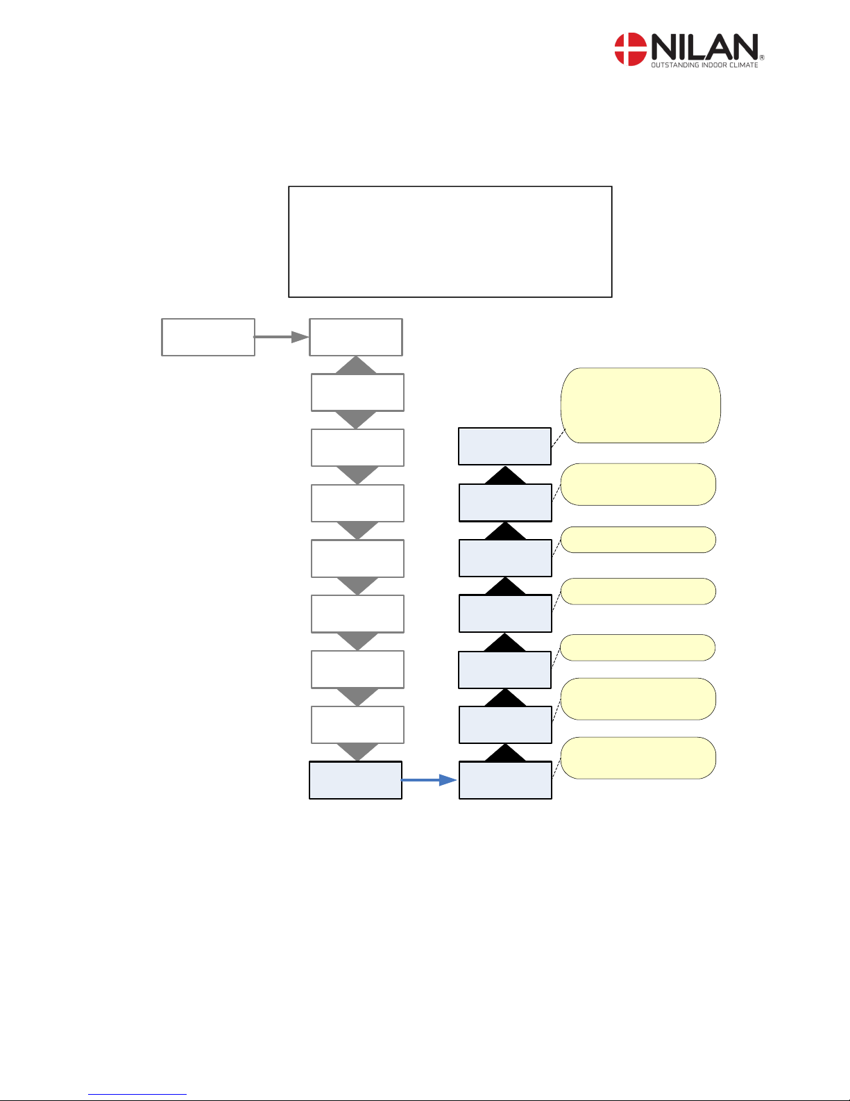
Manual
In the ”Manual” menu it is possible to test the functions of the unit manually.
” ” indicates that the menu point flashes and can be set to another value
Us e of t he CTS 600 panel :
- pr ess ESC t o go one st ep back i n t he me nu
- pr ess qpt o move up or down i n a me nu or t o
adj ust an act i vat ed menu
- pr ess ENTER t o a ct i va t e a menu
- pr ess ENTER t o c onf i r m a me nu
- pr ess OFF t o t ur n of f t he uni t
- pr ess ON t o t ur n t he uni t on
HEATING
SURFACE
AIR
EXCHANGE
DEFROST
TEMP.
CONTROL
ROOM
CONTROL
SERVICE
ENTER
INLET
CONTROL
RESTART
OFF
PRESET
OFF
MANUAL
OFF
MANUAL
”OFF”
ENTER
MANUAL
DEFROST
MANUAL
INLET
MANUAL
EXHAUST
MANUAL
VENT+CPR
MANUAL
VEN+HEAT
Manual test of ventilation
& heat. Under test there
are 50% signal to the
heating surface
Manual test of ventilation
& compressor
Manual test of exhaust
Manual test of inlet
Manual test of the
defrost function.
Manual test de-activated
(normal working)
MANUAL
FLAPS
Manual test of flaps
Figure 16: The "Manual" menu
Page 22
This document may be subject to change Side 22 of 23
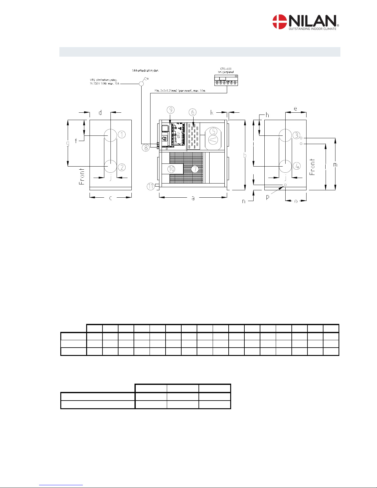
System dimension
Figure 17: System dimension
1. Fresh air intake. 5. Compressor 9. Inlet fan
2. Exhaust 6. Condensator (hidden) 10. Exhaust fan
3. Inlet 7. Evaporator 11. Condensation drain
4. Discharge 8. Electrical connections
Dimensions in mm:
a b c d e f g h i j k l m n o p
VPL15 650 680 400 200 200 90 410 90 410 Ø160 38 450 510 50 200 Ø20
VPL15T 550 600 635 50 95 190 140 140 160 160 160 160 - - - -
VPL25 700 760 570 285 215 160 480 205 505 Ø250 44 505 540 25 85 Ø20
Weight in kg.:
VPL15 VPL15T VPL25
Unit 54 50 65
Filterunit with Heat-pipe 30 - 40
Right
Left
Front
Page 23
This document may be subject to change Side 23 of 23
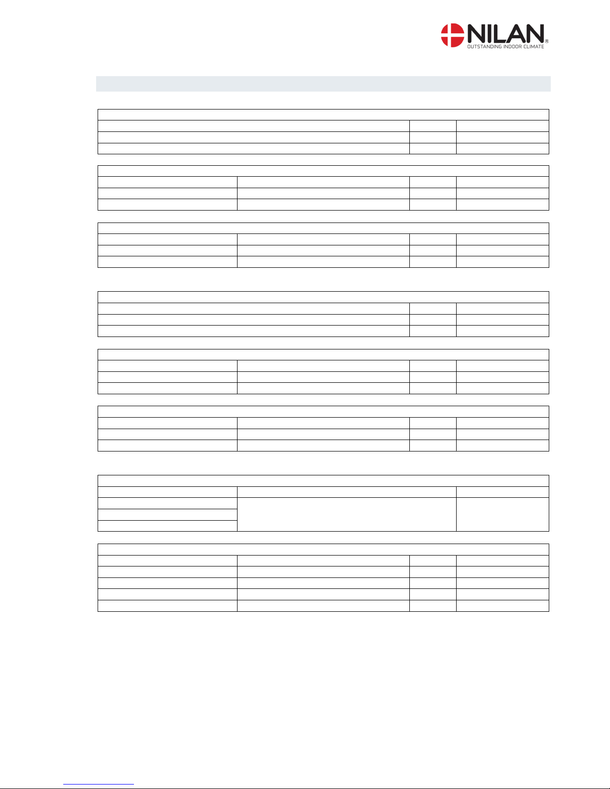
Accessories / spare parts
VPL 15
Filter types
Qty.
Nilan item no.
F5 (exhaust)
1
3953
F7 (inlet) 1 3952
VPL 15T
Filter types
Designation
Qty
Nilan item no.
T-filter, comlete
Ø160mm 1 8481
Filter for item no. 8481
Ø160mm 1 8504
VPL 25
Filterklasse
Designation
Qty.
Nilan item no.
T-filter, complete
Ø250mm 1 8484
Filter for item no. 8484
Ø250mm 1 85063
Heating surface, water
Unit
Qty.
Nilan item no.
VPL 15 + VPL 15T
1
768893
VPL 25 1 768983
Heating surface, electrical
Unit
Output
Qty.
Nilan item no.
VPL 15 + VPL 15T
0,9kW
1
76413
VPL 25
6,0kW
1
76423
Filterunit FU
Unit
Filter type
Qty.
Nilan item no.
FU15H
G3
1
3931
FU25H
G3
1
3932
Heating Cable for condensate drain (frost protection)
Unit
Designation
Nilan item no.
VPL 15
Heating Cable (specify length when ordering)
2172
VPL 15T
VPL 25
Vibration
Unit
Designation
Qty
Nilan item no.
VPL 15
Sylomer (Green)
4
30451
VPL 25
Sylomer (Green)
6
30451
FU15H
Sylomer (Green)
4
30451
FU25H
Sylomer (Green)
4
30451
 Loading...