


JVP 3*
Version: 6.00, 14-09-2012
Software 1.11
*This guidance applies to JVP 3 (740023, SW 1.09)
Installation and User Guide
LMC 223 by Nilan

All rights reserved Page 2 of 33
Table of contents
Table of contents ............................................................................................................................ 2
Figure ............................................................................................................................................. 3
Tables ............................................................................................................................................. 3
General information before installation ................................................................ ........................... 4
Safety ............................................................................................................................................. 5
System Design ............................................................................................................................... 6
Operation and maintenance ........................................................................................................... 7
Starting the heat pump ................................................................................................................ 7
Pressure in ground source loop (ground pipe)............................................................................. 8
Filling the ground source loop with brine ..................................................................................... 8
Water pressure in the central heating loop ................................................................................ 11
Filling water in the central heating loop ..................................................................................... 12
Dirt filters in central heating and ground source loops ............................................................... 12
Maintenance and Warranty ....................................................................................................... 12
Operation ..................................................................................................................................... 13
Menu Selection ......................................................................................................................... 13
Service Menu ............................................................................................................................ 13
Setting values ........................................................................................................................... 13
Language .................................................................................................................................. 14
Menu Summary ............................................................................................................................ 15
Operating Status Menu ............................................................................................................. 15
Operating Mode Menus ............................................................................................................. 15
Main Menus .............................................................................................................................. 15
Function Description ..................................................................................................................... 20
Heat pump compressor ............................................................................................................. 20
Frequency-controlled compressor (variable capacity) ............................................................... 20
Ground pipe and brine .............................................................................................................. 20
Condenser and heating circulation pump .................................................................................. 20
Permitted area of action for the heat pump ............................................................................... 21
Auxiliary heating ........................................................................................................................ 21
Central heating.......................................................................................................................... 21
Curve control via outside temperature ....................................................................................... 22
Frost protection ................................................................................................ ......................... 23
Alarm Menu .................................................................................................................................. 24
High pressure alarm .................................................................................................................. 24
Low pressure malfunction ......................................................................................................... 24
Leakage ................................................................ .................................................................... 25
Installation .................................................................................................................................... 27
Electrical connection ................................................................................................................. 28
The heat pump must be connected to electrical installation by an authorised electrician. .......... 28
Floor heating loop ..................................................................................................................... 28
Ground source loop .................................................................................................................. 28
Testing for leaks: ....................................................................................................................... 30
Brine filling ................................................................................................................................ 30
Safety ground coil system ......................................................................................................... 30
Isolation of the tubes ................................................................................................................. 30
Drainage and collection tray ...................................................................................................... 30
Disposal of the heat pump ........................................................................................................ 30
Check list for brine/water pump system at start-up and commissioning ........................................ 31

All rights reserved Page 3 of 33
Figure
Figure 1: Example of system design ............................................................................................... 6
Figure 2: JVP 3 installed with Compact P ....................................................................................... 7
Figure 3: LMC 223 Control Unit .................................................................................................... 13
Figure 4: Curve Selection for external temperature compensation ................................................ 22
Figure 5: Structural ground source pump system diagram. ........................................................... 27
Figure 6: Example of layout of ground pipes in a collector. ........................................................... 29
Figure 7: Example of layout of ground pipes with collection inside footing. ................................... 29
Tables
Table 1: List of Alarms .................................................................................................................. 26

All rights reserved Page 4 of 33
General information before installation
Check that the following documents have been supplied with the unit:
- Installation and User Guide (this document)
- Wiring diagram
If you have any questions concerning installation after reading the guide, please contact your local
Nilan dealer. Find your local dealer here: www.nilan.dk/forhandlere
Control of the system is via a NILAN LMC 223 control unit, which offers a wide range of functions,
for example, menu-driven control, summer/winter operation, outside compensated control, etc.
Before the establishment of a geothermal system, any permits and approvals must be obtained
from relevant authorities.
The Geothermal heat pump JVP is designed for heating homes with low temperature heating systems with forward-flow temperatures of up to 45 °C.

All rights reserved Page 5 of 33
Safety
Always disconnect the electrical supply to the heat pump if any malfunction occurs
that cannot be remedied via the control unit.
If any malfunction arises on the electrical part of the heat pump, always contact a
licensed electrician to repair the fault.
Avoid direct contact with the heating system pipes in the heat pump, as they can
be very hot.
Many types of antifreeze are hazardous to health, dangerous when ingested, and
must be kept out of the reach of children.
To protect the heat pump from damage, it is supplied with the following safety
equipment:
Expansion systems for central heating and brine/ground source loop
Safety valves for central heating and brine/ground source loop
Low and high-pressure cut-off switches for compressor
Pressure guard brine loop/ground pipe (mandatory environmental
pressure switch)
Minimum/frost thermostat (cuts off the heat pump if the temperature
becomes too low in the brine loop)
The heat pump must be serviced in accordance with applicable legislation and
regulations to ensure that the system is responsibly maintained and complies with
safety and environmental requirements.
Responsibility for maintenance of the heat pump rests with the owner or user. The
ground source loop contains antifreeze, which can compromise groundwater if
spilled or leaked. Contact an authorised service technician immediately if you suspect there is a leak in your ground source heat system.

All rights reserved Page 6 of 33
System Design
Electrical installation/power supply (including safety switch) should be installed by an
authorised electrician.
Connect the unit according to the wiring diagram supplied.
Figure 1: Example of system design
Function of ground source heat system
The Geothermal heat pumpJVP is designed for heating homes with low temperature heating systems with forward-flow temperatures of up to 45 °C, for example floor heating systems.
System components (function)
The ground source heat system obtains heat from the ground through the ground pipe loop (3).
The ground stores heat, which it accumulates from the sun in the summer and releases the heat to
the ground pipe loop (3) in the winter. The temperature in the water/antifreeze mixture (= brine);
from the ground pipes (1). Brine to be protected against freezing form a freezing point of -20 °C to
-18 °C. To exploit the heat energy in the brine, the system uses a heat pump to transfer energy
from a low temperature in the brine to a higher temperature in the central heating system. Circulation pumps (8) maintain flow in both the ground pipe loop (3) and the central heating/floor heating
loop (10).
The heat pump consists of an evaporator (4), compressor (5), condenser (6) and an expansion
valve (7). These elements are connected and filled with a refrigerant in a closed cycle in a closed
system. The antifreeze in the ground source loop is heated by the ground and cooled in the evaporator. After the evaporator the refrigerant is compressed in the compressor and the temperature
and pressure of the refrigerant are increased. In the heat exchange process in the condenser, the
refrigerant then releases heat energy to the central heating water, and the temperature of the central heating water rises. After the condenser the refrigerant pressure is reduced in the expansion
valve, and the refrigerant continues into the evaporator where it cools the brine before flowing return into the ground pipe loop (2).
An auxiliary heating element (9) is installed in the central heating loop, which can supplement the
ground source loop in the event of particularly high heating demand.

All rights reserved Page 7 of 33
Operation and maintenance
When setting up the system, future service and maintenance should be taken into account.
Minimum clearance in front of the system of at least 1m is recommended.
Starting the heat pump
Before starting the heat pump, check the following:
Pressure in the central heating system, see Figure 5 no. 17
Pressure in the ground loop, see Figure 5 no. 17
Check that both the central heating loop and the ground source loop have been ventilated.
The central heating circuit has an excess flow valve or other circulation, which ensures the
flow, see Figure 5, no 28
Check list for brine/water pump system at start-up and commissioning (see page 29) must be reviewed before starting.
The heat pump can then be switched on at the safety switch.
The heat pump is shut off at the safety switch.
Figure 2: JVP 3 installed with Compact P
1 central heating inflow - (3/4”)
2 central heating return - (3/4”)
3 brine inflow from ground pipe - (1”)
4 brine return from ground pipe - (1”)
5 safety valve - brine loop
6 manometer - brine loop

All rights reserved Page 8 of 33
Pressure in ground source loop (ground pipe)
The pressure must be inspected as often as several times a day in the initial days. If necessary,
the system must be topped up with brine. See Figure 5, no. 17
Brine pressure will stabilise after a few days and inspection can then be reduced to once a month.
It is important that brine pressure is correct. Too little pressure in the ground source loop can/will
trigger the alarm device in the ground source heat system. (low pressure)
Brine may have to be added a couple of times during the first year in connection with ventilation of
the ground source loop.
Filling the ground source loop with brine
The brine in the ground source loop comprises water and antifreeze. Ethanol, IPA alcohol, ethylene glycol or propylene glycol.
The heat pump is equipped with a low-pressure switch, which ensures that the brine never becomes so cold that it freezes solid, and thus the ground source heat pump's heat exchanger is
protected against frost damage.
The frost protection mixture must be adapted to the operating temperatures in the ground source
loop. It is very important that the frost protection fluid is mixed thoroughly before it is added to the
ground source loop as no mixing takes place in the ground pipes. Failure to do so increases the
risk of the heat pump freezing, thus creating a potential risk of frost damage. Brine may only be
added/topped up by an authorised technician. Before loading, check that the ground coils are tight.
How to fill brine into the ground source loop before start:
Switch off the heat pump and the circulation pump at the main switch before filling
brine into the system
Shut off one valve at the circulation pump of the brine circuit. Figure 5: Structural
ground source pump system diagram.

All rights reserved Page 9 of 33
, item 18 and 19
By means of a combined filling and venting tank, the brine loop is filled through the
filler tap until the loop is compeletely full Figure 5: Structural ground source pump
system diagram.

All rights reserved Page 10 of 33
, item 13. Duration minimum 1 hour.
The shutter tap at the cirkulation pump in the brine loop Figure 5: Structural ground
source pump system diagram.

All rights reserved Page 11 of 33
item 18 and 19, is reopened, and the pump is filled up and vented
If brine has to be repeatedly added to the ground source loop, this indicates that the ground pipes
are leaking.
ALWAYS contact an authorised service technician immediately if you suspect leakage.
Water pressure in the central heating loop
The water pressure in the central heating loop must initially be inspected as often as several times
a day. Top up the system with water, if necessary, see Figure 5 item 13
The water pressure will stabilise after a few days and inspection can then be reduced to once a
month. If you have to add water to the central heating loop beyond the start-up phase, the system
must be checked for leaks.

All rights reserved Page 12 of 33
Filling water in the central heating loop
Switch off the heat and circulation pumps at the main switch.
Fill water into the central heating loop via the filler cock, Figure 5, item
13, until the correct water pressure is achieved, Figure 5, item 17
The automatic vents on the heat tank, central heating loop, etc., are
activated automatically when water is added to the system.
Add water to the system until the water pressure is correct. If the wa-
ter pressure disappears entirely during filling, filling must be restarted
right from the beginning.
Restart the heat pump at the main switch.
Dirt filters in central heating and ground source loops
Immediately after the heat pump has been commissioned, a certain amount of dirt can accumulate
in both loops. The dirt filter is located in the central heating string and in the ground pipe string outside the heat pump, as shown in Figure 5
The filters must be checked and cleaned several times daily after installation of the heat pump until
the filters remain clean. In normal operation of the heat pump, it should be sufficient to check the
filter twice a year.
Cleaning the dirt filters:
Switch off the heat pump at the main switch.
Close the shut-off valves on each side of the filter.
Pull out filter and rinse until clean.
Replace the filter and open the shut-off valves. Then switch on the
heat pump at the main switch.
Maintenance and Warranty
The heat pump must undergo appropriate service in accordance with applicable laws and regulations in order to keep the plant maintained in good condition and to fulfill demands on safety and
environmental compliance. It is recommended that the owner / operator immediately after commissioning of the facility shall consult with a qualified service technician about the scope and
frequency of servicing.
The responsibility for maintenance of the heat pump is for the owner’s / user’s. Geothermal circuit
containing coolant that can harm groundwater by leakage. Immediately contact a qualified service
technician by suspected leaks in your geothermal system.
The installer of heat pump is obliged to provide an assurance to the owner / operator in accordance with applicable laws and regulations. For specific warranty terms refer to the owner / user
agreement with his supplier.
A prerequisite for warranty obligation is that servicing and maintenance is carried out as described.

All rights reserved Page 13 of 33
Operation
The JVP is equipped with a control unit (see below).
Figure 3: LMC 223 Control Unit
The control unit is used to control heat pump operation.
The unit has 2 diodes to the left of the display:
- the upper diode is illuminated when the heat pump is operating.
- the lower diode is illuminated when the auxiliary heating is operating.
The backlight in the display flashes when the system's alarm device is triggered.
Nilan LMC220 control unit is controlled solely by turning the knob to the right of the display. The
knob has three functions:
- Turn clockwise: Go to next menu item or increase the last value in the display.
- Turn anticlockwise: Go to previous menu item or reduce the last value in the display.
- Press: Select sub-menu, activate adjustment of value, or approve the last value.
The light in the display is illuminated when the unit is being operated. The light switches off after 30
seconds if the unit is not activated by the user. The control unit will revert to the start screen (status
menu) after five minutes if the unit is inactive.
Menu Selection
To switch between the menus, turn the knob.
Menus with an arrow at bottom right also have a sub-menu. To activate a sub-menu, press once
on the knob. To switch between sub-menu items, turn the knob. To exit the sub-menu, turn forward
or back until "Menu up" appears in the display. Then press the knob.
Service Menu
The sub-menus in the service menu are not accessible during normal operation. They are for use
in connection with installation and service.
Setting values
To set values in the display:
- Turn the knob until the value you wish to change is shown in the display.
- Press the knob to activate the value. The value will flash, if it can be changed.
- To change the value, turn the knob.
- Press the knob to accept the value shown. The value will stop flashing.

All rights reserved Page 14 of 33
Language
At the bottom of the service menu, you can select various languages:
- Turn the knob clockwise until the service menu is displayed.
- Press the knob to activate the service menu.
- Turn the knob until the LANGUAGE menu is shown in the display.
- Press the knob. The text in the display flashes.
- Turn the knob forward or back until the desired language is displayed.
- To approve the language, press once on the knob. The text stops flashing.

All rights reserved Page 15 of 33
Menu Summary
Operating Status Menu
The system's current operating status is displayed as the initial screen in the main menus.
OFF
The system is switched off. All functions are inactive, except:
- Alarm from ground pipe environmental pressure switch
- Circulation pump periodic test run and frost protection
START
Start heat pump. Circulation pumps start. Switch after a short time to operational
READY
The system is switched on but there is no current heat demand
HEATING
Room heating. Central heating temperature in the house at the desired value
WATER
Domestic hot water production
MANUAL
The user has activated manual operation via the service menu
ALARM
Alarm device triggered. The system continues to operate but with reduced function
STOP
The system was stopped due to a critical malfunction
Operating Mode Menus
In the OPERATION menu, the following operating modes can be selected:
OFF
No heating functions are active
SUMMER
Normal condition is domestic water. Central heating is not active
WINTER
Normal condition is central heating, which switches to domestic water as needed
AUTO
The system selects operating mode based on average outside temperature,
set summer temperature and a 3°C neutral zone
- Winter: After 24 hours under summer temperature minus neutral zone
- Summer: After 24 hours above summer temperature
When user function HEATING has been choice in "SELECT" in the "SERVICE",
summer/winter mode is chosen by an external signal on digital input DI4
Main Menus
Parameters in blue text below can be adjusted by authorized service personnel / user. The product
is delivered with factory settings as indicated.
Shaded cells must often change
STATUS *
HEATING
Readout of current operation status text
* Symbol indicates that a user function is active on the digital input
This is the main screen
OPERATION
WINTER
The unit's main switch and selection of overriding operating mode
In operating mode AUTO the choice can be by user function HEATING on digital input. [OFF, SUMMER, WINTER, AUTO]
T USER
EXT 15°C
Alternative setting selected via user function digital input
(shown only if a user function with setting is selected (COOL, DELAY)
READOUT
Sub-menu for display of current sensor and control data
T WATER
45°C
Domestic water tank temperature
T HEAT*
CURRENT
33°C
Central heating temperature
T HEAT*
SET 32°C
Current setting for central heating temperature. Recommended flow central
heating temperature is 30 ° C to 45 ° C. Fixed value or variable value using
outdoor compensation.
T OUT
12°C
Outside temperature
EVAP. T
-2°C
Evaporator temperature, Indicates the temperature of the cooled brine in the
evaporator
CP CAP
60 %
Current compressor capacity (%)
(shown only if compressor speed control is selected)
CURVE
+/- 0°C
Raises or lowers the calculated curve setting a fixed value (°C) [-9..9] (shown
only if curve control is selected) - See the menu CENTRAL HEAT
* Version 1.09 displayed T HEAT as T RETUR

All rights reserved Page 16 of 33
... Menu continued from previous page:
SET
Menu normally hidden
(to activate this menu, press knob for 8 secs while the Status Menu is active)
HEATING
PUMP
AUX
OFF
Auxiliary heating released for operation (for both domestic water and central heating)
[OFF, ON]
DELAY
AUX 30m
Delaying connection of auxiliary heating gives the heat pump a better chance to meet
demand
[0..60]
RESTART
CP 30m
Compressor restart time to prevent unnecessary wear (between two consecutive starts)
[2..60] minutes
STOP
CP 10m
Minimum stop time for the compressor (time from stop to start)
[0..15] minutes
COMPRESS
MIN OFF°C
Minimum outside temperature for compressor operation. If colder, stopped compressor
and EL takes over [OFF, -25..-10] °C
COMPRESS
MAX 47°C
Max temperature to permit compressor running. (stop to avoid pressure overload of
condenser)
[40..80] Max. Temperature is Twater (T2) for SHWt and Theat (T1) for central heating.
T SUMMER
15°C
Level for automatic switch between summer and winter operation
[0..30]
CP LEVEL
RPM
Select compressor operating mode on/off or RPM regulation
[1 LEVEL, RPM]
STOP %
10
Compressor stop capacity
(shown only when RPM compressor level selected)
ST DIFF%
40
Compressor start difference
(shown only when RPM compressor level selected)
U MIN %
25
Minimum voltage to frequency converter
(shown only when RPM compressor level selected)
U MAX %
100
Maximum voltage to frequency converter
(shown only when RPM compressor level selected)
U START%
70
Initial voltage to frequency converter
(shown only when RPM compressor level selected)
U 60°C %
MIN 30
Compressor RPM limit in heating operation as a function of the current setting - curve
max. [MIN, OFF] (shown only when RPM compressor level selected)
U 40°C %
MIN 20
Compressor RPM limit in heating operation as a function of the current setting - curve
min. [MIN, OFF] (shown only when RPM compressor level selected)
GAIN
7
Enhancement of PI regulator (factory setting: 5 % per ℃)
(shown only when RPM compressor level selected)
TN
3m
PI regulator integration period (factory setting: 5 minutes)
(shown only when RPM compressor level selected)
VENT HI
50
Capacity for transfer between high/low ventilator speed
U LOW %
50
Voltage for low ventilator capacity
U HI %
100
Voltage for high ventilator capacity
CIRCPUMP
CONTIN
Select operating mode for central heating circulation pump (on/off only with buffer tank)
[CONTIN, ON/OFF]
Important:
The parameters menu HEATPMP must be set by authorized service personnel.
Parameters in gray boxes changed as required, while the other parameters should not be
changed.

All rights reserved Page 17 of 33
... Menu continued from previous page:
DOMESTIC
WATER
Geothermal heat pump JVP is designed for HEATING
For SHW it should only be used as back-up or as preheating
HEATING
OFF
Heat source selection for domestic water production
[OFF, HP, AUX, HP+AUX]
MINIMUM
35°C
Temperature setting for auxiliary heating (if released and selected)
[5..80]
SETTING
45°C
Temperature setting for heat pump compressor
[5..60]
NEUTRAL
ZONE 4°C
Dead time for connecting. Heating starts at setting minus this value
[1..9]
CP CAP
60 %
Compressor capacity during domestic hot water production. (Factory setting 60 %)
LEGIO
DAYS OFF
Legionella function frequency (auxiliary heating must be released for operation)
[OFF, 7..30] days
CENTRAL
HEAT
CTR HEAT
HP+AUX
Heat source selection for room heating
[OFF, HP, AUX, HP+AUX]
T HEAT
MIN 35°C
Setpoint of the housing central heating temperature and setpoint-heating [5 0.60].
Recommended central heating temperature is 30 ° C to 45 ° C. By TEMP CTR, AMB
COMP will restrict the central heating temperature, downwards, and must therefore
be adjusted the curve.
T HEAT
MAX 45°C
The maximum permitted setpoint for the building central heating temperature
[5 0.60] By TEMP CTR, AMB COMP will restrict the central heating temperature up
to MAX
NEUTRAL
ZONE 3°C
Dead time for connecting. Heating starts at setting minus this value
[1..9]
TEMPCTRL
MIN
Central heating temperature control function
[MIN, OUT COMP]
CURVE
SELECT
5
Outside temperature compensation curve (Curve Menus displayed if selected under
CONTROL) [DEF, 1..10]
CURVE
+/- 0°C
Raises or lowers the calculated curve setting a fixed value (°C)
[-9..9]
CURVE 20
DEF 50°C
Manually-selected five-interval out/in curve (at -20, -10, 0, 10 and 20 °C) for central
heating temperature [5..60]
CURVE 10
DEF 45°C
CURVE 0
DEF 40°C
CURVE+10
DEF 35°C
CURVE+20
DEF 30°C
Parameters menu, DOMESTIC WATER and CENTRAL HEAT needs to be set by authorized service personnel
Parameters in gray boxes changed as required, while the other parameters should not be changed
* Version 1.09 displayed T HEAT as T RETUR

All rights reserved Page 18 of 33
DEFROST
TYPE
OFF
Choosing the defrosting method
[OFF, HOTGAS, AIR, AIR+HG]
MAN DEFROST
OFF
Not a function of Geothermal heat pump system
ICE LEVEL
-2 °C
Not a function of Geothermal heat pump system
ICE ACC
20 m
Not a function of Geothermal heat pump system
STOP T
8 °C
Not a function of Geothermal heat pump system
MAX TIME
8 m
Not a function of Geothermal heat pump system
DEFROST
CAP 80 %
Not a function of Geothermal heat pump system
NUM HG
0
Not a function of Geothermal heat pump system
NUM AIR
0
Not a function of Geothermal heat pump system
LAST DE-
FROST 0 m
Not a function of Geothermal heat pump system
INTERVAL
240 m
Not a function of Geothermal heat pump system
MIN TEMP
-15 °C
Minimum evaporator/brine temperature. (frequency converter operation only)
Important:
The parameters in menu DEFROST must be set by authorized service personnel.
Parameters in gray boxes changed as required, while the other parameters should not be
changed.

All rights reserved Page 19 of 33
... Menu continued from previous page:
ALARMS
ALARM 0
NONE
Display of up to three current alarms
Data readout (code and text) for each alarm line. Reset in the event of power outage
ALARM
LOG
Alarm log stores and displays the last 16 active alarms
NOT reset in the event of power outage
AL 0: 13
T2 SHORT
Most recent active alarm
AL 1: 20
PRESSURE
Next most recent active alarm
Service menu activated using key combination:
SERVICE
Service menu for set-up, testing and troubleshooting
Normally hidden menu (activated by holding the button down for 8 seconds while the
status menu is active)
LMC 223
VER 1.09
Unit type identification and software version number
RESTART
CP 914s
Seconds until release of compressor restart
Can be reset for service purposes
USER
FUNCT
Menu for setting user-selected functions
SELECT
NONE
Select user function in digital input DI4
[NONE, DEFROST, COOL, DELAY, HEATING)
MANUAL
Manual activation of relay outlets
ACTIVATE
NO
Activation of manual operation
[NO, YES]
COMPRESS
OFF
Start compressor
[OFF, ON]
AUX
OFF
Start auxiliary heating
[OFF, ON]
3-WAY
OFF
Activate 3-way valve for domestic water
[OFF, ON]
BRINE
PUMP
OFF
Start ground pipe brine pump
[OFF, ON]
CIRCPUMP
OFF
Start central heating circulation pump
[OFF, ON]
OPERTIME
Operating hours counter
HEAT
PUMP
8206h
Indicates how long the heat pump has been switched on
COMPRESS
2184h
Compressor
AUX
514h
Auxiliary heating
3-WAY
0h
3-way valve for domestic water
BRINE
PUMP
4740h
Ground pipe brine pump
CIRC
PUMP
2948h
Central heating circulation pump
SETUP
GUIDE
Menu which leads the user through the selections that have to be made to set up the
system
...
LANGUAGE
ENGLISH
Section of user interface language
[ENGLISH, DANISH, GERMAN]
Important:
The parameters in menu SERVICE must only be set by authorized service personnel.
Parameters in gray boxes changed as required, while the other parameters should not be
changed.

All rights reserved Page 20 of 33
Function Description
Heat pump compressor
The system is protected with high and low-pressure switches that can stop the compressor and
trigger an alarm.
By heating demand the heat pump compressor starts when the temperature has dropped to setpoint minus the neutral zone. When the compressor is operating the central heating temperature is
raised up to the respective set point before it goes out. The neutral zone helps to avoid frequent
start / stop.
Frequency-controlled compressor (variable capacity)
The frequency is controlled by a PI regulator. The PI regulator parameters are set in the HEATING
PUMP menu.
OTo avoid frequent ON / OFF couplings on the compressor because of the large hysteresis on
central heating temperature, the compressor starts only when the PI controller's capacity reaches
above 40%. The compressor stops when PI regulator capacity falls to under 10 %.
If the compressor continues to start/stop at short intervals, it may be necessary to set a wider neutral zone (in the CENTRAL HEAT / NEUTRAL ZONE Menu).
Ground pipe and brine
The brine pump always runs with the compressor and starts 1 minute before and runs 1 minute
longer. After a week of inactivity, the pump starts briefly to prevent blockage.
The environmental pressure switch triggers an alarm and stops the system if there is a leak in the
brine system.
Condenser and heating circulation pump
The system has a water-cooled condenser with a circulation pump.
To prevent excessive condenser pressure in the event of failure of the high pressure switch, hot
water is circulated in the central heating system until the temperature falls below the set maximum
value for the compressor, before the compressor is started.
After a week of inactivity, there is a brief periodic test run.
In addition the pump has the following operating modes, which depend on the overriding control
mode:
- Winter operation: The pump runs constantly.
- Summer operation: The pump is inactive (except for brief periodic test run).

All rights reserved Page 21 of 33
Permitted area of action for the heat pump
- Brine temperature to the evaporator from ground hoses -5 °C to +20 °C
- Central heating flow temperature +24 °C to +55 °C
It is recommended to use JVP for central heating systems with a flow temperature of 30 °C to 45
°C, to obtain an energy-efficient operation and less wear on the heat pump compressor.
Installation location:
- Room temperature 5 °C to 35 °C and a relative humidity of 30-70%
Auxiliary heating
A 2.0 kW electric water heater is connected as a supplement to the heat pump, in the event that it
cannot supply the desired heating, for example, in cold and windy weather.
The auxiliary heating must be released for operation by the user. The auxiliary heating is activated
if the forward water temperature falls below the minimum set value (minus neutral zone). The system thus ensures that the heat pump supplies the greatest share of energy. At the same time, the
user, even during extraordinary demand, is ensured a well-defined comfort. The heat pump is delivered with optional additional heating turned off (OFF) as factory setting.
The auxiliary heating will also be used as a reserve supply and to maintain normal comfort in situations where the heat pump is not operating due to installation work, a fault, etc. Under these
circumstances, the compressor settings are overridden so that the auxiliary heating is not controlled by minimum values.
Central heating
During regular heat pump operation, compressor capacity is adjusted thus maintaining a predetermined central heating temperature in the house. The required central heating temperature depends
on the heating demand in the house, which in turn depends on its size, insulation and the outside
temperature. Several different temperature compensation modes can be selected. These can be
activated separately or simultaneously.

All rights reserved Page 22 of 33
Curve control via outside temperature
You can pre-program the house's return flow setting in accordance with the outside temperature, if
OUT COMP is selected as the control mode for central heating. This requires that the outdoor sensor is mounted.
The desired heating temperature is set to an outdoor temperature of -20 ° C, -10 ° C, 0 ° C, 10 ° C
and 20 ° C. On the basis of these temperatures, the central heating temperature is determined by
interpolating between the points for a given outside temperature, see Figure 4
For outside temperatures under -20 °C and over 20 °C, the programmed forward central heating
temperature is used for -20 °C and 20 °C respectively.
In the control menu CTR HEAT MIN and MAX are set. MIN and MAX can limit the control curve
upwards and downwards.
You can select from 10 pre-programmed curves or create a user-defined one.
Outside temperature
central heating temperature
Figure 4: Curve Selection for external temperature compensation

All rights reserved Page 23 of 33
Frost protection
A number of functions are built into the system to prevent frost damage. These functions are always active regardless of the operating modes and settings selected (including OFF). Any missing
or defective temperature sensors or system components can of course render this protection ineffective:
- When the outside temperature falls below 2 °C, the central heating circulation pump will
start. With that, any spaces under the eaves and any attic space are secured and you can
also monitor water temperature.
- If the central heating or room sensors fall below 2 °C, all circulation pumps will start, along
with the heat pump and auxiliary heating, and temperatures will, if possible, be raised to
5°C.

All rights reserved Page 24 of 33
Alarm Menu
The Alarm Menu displays any alarms and an alarm overview for the last 16 alarms. (see ALARMLOG).
If an alarm is triggered, the backlight in the display will flash. Operating status switches to ALARM
or STOP. You can read the cause of the alarm in the ALARM sub-menu.
The alarm is displayed with an alarm code. When the cause of the alarm is removed, the alarm
switches automatically from active to inactive and the backlight stops flashing.
To acknowledge an alarm, press the knob in the sub-menu ALARM when the alarm is displayed.
The alarm is then deleted from the alarm log.
Active alarms cannot be acknowledged before the system has registered that the alarm cause has
been eliminated.
There are three alarm levels:
INFO : General information for the user that does not affect operation.
WARNING : Given in the event of alarms, which permit continued operation with small
inconveniences.
CRITICAL : This type of alarm means that operation stops entirely or is significantly reduced.
High pressure alarm
Refrigerant pressure in the condenser is too high. This is due to the fact that the heat pump cannot
clear the heat it is producing. The central heating water is circulating too slowly.
Possible causes:
1. Dirt filter in the central heating system is clogged
2. There is air in the central heating system – ventilate the system
3. There is insufficient water in the central heating system.
4. The “hot pump” to the central heating system is not running. The pump should
buzz quietly when operating
Check 1 – 4 and correct the fault. Acknowledge the alarm by pressing the knob in the Alarm submenu when the alarm is displayed.
Low pressure malfunction
Refrigerant pressure in the evaporator is too low. This is due to the fact that there is not enough
heat coming from the ground source loop. Either the brine is circulating too slowly or the brine is
too cold when it returns from the ground loop.
Possible causes:
1. There is air in the ground pipes – ventilate the ground heat loop/ground pipes
2. There is insufficient brine in the ground pipes
3. The brine has frozen in the heat exchanger. The “cold pump” will be very hot
4. The “cold pump” to the ground pipes/ground source loop is not running. The
pump should buzz slightly while operating
Check 1 – 4 and correct the fault. Acknowledge the alarm by pressing the knob in the Alarm submenu when the alarm is displayed. Contact a service technician if the low pressure switch shuts
down the system again after a few minutes. Don not attempt to start the system repeatedly, as this
increases the risk of frost damage to the heat pump evaporator.

All rights reserved Page 25 of 33
Leakage
The pressure is too low in the ground pipes/ground source loop. This may mean that the ground
pipes are leaking.
Check the following:
1. Are all cocks open that should be open?
2. Is there enough brine in the system? Top up if necessary.
Check 1 – 2 and correct the fault. Acknowledge the alarm by pressing the knob in the Alarm submenu when the alarm is displayed. Call a service technician if you cannot locate the fault yourself.

All rights reserved Page 26 of 33
No.
Text
Type
Action
Description
5
DATABASE
I
--
The control unit has been reset to the factory setting
and requires a renewed default setting. This occurs,
for example, if software is updated with a new program that differs significantly from the old one.
- Make the desired settings via the menu system
10
T1 OPEN
C
STOP
Central heating temperature sensor disabled
- Check connection. Replace sensor if necessary
11
T1 SHORT
C
STOP
Central heating temperature sensor disabled
- Check connection. Replace sensor if necessary
12
T2 OPEN
C
STOP
Domestic water temperature sensor disabled
- Check connection. Replace sensor if necessary
13
T2 SHORT
C
STOP
Domestic water temperature sensor disabled
- Check connection. Replace sensor if necessary
14
T3 OPEN
W
7°C presumed
Outside temperature sensor disabled
- Check connection. Replace sensor if necessary
15
T3 SHORT
W
7°C presumed
Outside temperature sensor disabled
- Check connection. Replace sensor if necessary
16
T4 OPEN
W
Deactivate room
control
Brine temperature sensor disabled
- Check connection. Replace sensor if necessary
17
T4 SHORT
W
Deactivate room
control
Brine temperature sensor disabled
- Check connection. Replace sensor if necessary
32
LOW PRS
C
Stop compressor
auxiliary heating
takes over heating
Low pressure alarm. The heat pump will start automatically two minutes after the alarm has
disappeared.
33
HIGH PRS
W
Stop compressor
auxiliary heating
takes over heating
High pressure alarm. The heat pump will start automatically 2 minutes after the alarm has disappeared.
See also Alarm 34.
34
RESTART
C
Stop compressor
auxiliary heating
takes over heating
Safety shut-off from compressor high pressure. After
three high-pressure alarms (code 33) within 12 hours,
alarm 34 is triggered. Alarm 34 includes manual reset. The compressor will not restart until you have
acknowledged Alarm 34 in the Alarm Menu.
34
RESTART
W
Aux heating
takes over after 5
mins.
Safety shut-off from compressor high pressure and
low pressure
- Compressor restarts when user acknowledges the
alarm
50
FROST
W
Circulation
pumps are started.
Temperature for domestic water, central heating or
room sensor has fallen below 2°C for more than two
hours. Frost protection function is active
53
LÆK
W
Aux. heatin takes
over after 5 mins.
Ground pipe environmental pressure switch
- Check system for leaks
54
OVERHEAT
C
STOP
Forward or domestic water overheated to 90°C or
more
- Check relays and contacts to compressor and auxiliary heating
70
LEGIO
I
--
The Legionella function has not been performed within the deadline in two successive weeks.
- Insufficient heat energy supplied from brine or auxiliary loop
Table 1: List of Alarms

All rights reserved Page 27 of 33
Installation
Figure 5: Structural ground source pump system diagram.
All rights reserved Page 28 of 33
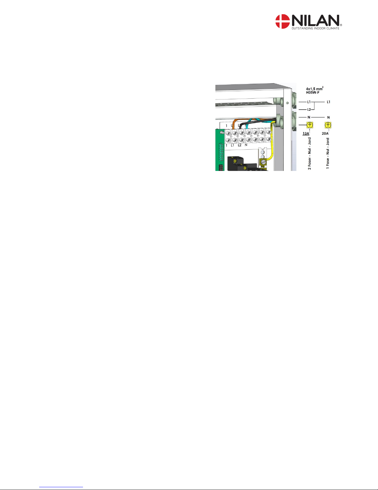
Electrical connection
The heat pump must be connected to electrical installation by an authorised electrician.
2x230 V, N + PE, - 13 A, 50 Hz
1x230 V, N + PE, - 20 A, 50 HZ
Supply cable: 4x1,5mm², HO5W-F
The supplied electrical diagram shows how to
connect the system to the grid
Floor heating loop
IMPORTANT: An overflow valve must be installed (Figure 5, no. 28) in the floor heating loop with a
fixed-speed circulation pump. Alternatively, individual thermostats must be installed to maintain
sufficient flow.
It is possible to connect an external run signal to the pump control unit (see wiring diagram) from
eg a floor heating system.
Starting with software version 1.10 of LMC223, this works as an external summer-/winter shift. In
the controller menu SERVICE SELECT USER FUNK can be select HEATING. . When HEATING is
chosen you make and extreme change between winter - and summer operation. The controller is
forced to run in winter operation when the digital input 4 is close. Conversely, the control is forced
to run in summer operation when the digital input 4 is open. In winter operation the pump in central
heating is running. User Function HEATING assumes that the system is in DRIFT-AUTO.
Ground source loop
When setting up a ground source loop, there are a number of clearance requirements which must
be complied with to ensure efficient and trouble-free operation. Furthermore, local authorities often
stipulate their own requirements for installation and approval of the system before it is commissioned.

All rights reserved Page 29 of 33
Figure 6: Example of layout of ground pipes in a collector.
Figure 7: Example of layout of ground pipes with collection inside footing.

All rights reserved Page 30 of 33
Testing for leaks:
As cracks in the pipes can occur during handling/transport, it is important to pressure test the pipes
individually for leaks immediately before covering with earth. Testing for leaks should be carried
out in accordance with the applicable regulations.
Brine filling
After completed and substantiated testing for leaks, the system can be filled with brine. Brine filling
should be performed by an authorised technician. Brine can be purchased ready-mixed with corrosion inhibitors or the fluid can be mixed before filling. We recommend that you use ready-mixed
brine containing corrosion inhibitors. If mixing the brine yourself, the water quality must be appropriate to brine and to the materials in the system. In the case of ready-mixed brine, product safety
data sheets are enclosed which document the composition of the brine. Brine and water must be
mixed thoroughly before filling; a bulk container can be used, for example. Use a powerful pump to
remove air pockets from the ground pipes before filling them with brine. Calculate pumping time for
filling the system at an established pumping rate. It will not take less than the calculated pumping
time to fill the system with brine. Prevent air from entering the ground pipes during filling.
Safety ground coil system
The ground source heating pipes are equipped with a low pressure switch which triggers an alarm
in the event of a fall in pressure in the ground pipe. In the event of an alarm, the system must be
disconnected and prevented from restarting automatically. The ground pipe system must be dimensioned as a closed system with a standing pressure of 150-250 kPa.
Isolation of the tubes
All piping to and from the ground tubes / geothermal heating circuit must be insulated up to the
heat pump, so that no condensation occur on the cold pipes.
Drainage and collection tray
There may be advantageously established drains condensate from the heat pump and water from
the safety valve during heat pump. It is mandatory to established collection tray at the safety valve
on the collector side.
Disposal of the heat pump
Please contact your municipality or its authorized installer, when the heat pump must be disposed,
as the heat pump and brine must be disposed in accordance with applicable laws.

All rights reserved Page 31 of 33
Check list for brine/water pump system at start-up and commissioning
The check list must be followed at start-up and commissioning of the complete heating system.
Reference is made to the text in the manual for further details.
Before the system is put into opereation the following item must be checked and notes made.
Brine circuit
Control
Yes/No
Memo
Date
Brine heat/source circuit is tight?
Brinetype
N/A
Brine concentration %
N/A
%
The brine concentrationen, freezing temperature
(registered -20°C til -18°C)
N/A
°C
The brine is properly mixed prior to filling of the
circuit?
The brine cicuit is purge of air?
The pressure of the brine circuit, bar gauge
N/A
bar
Any leakage from the relief valve must be collected. Brine must not run into any sewers
The brine circuit is connected correctly to the heat
pump (which can be damage)
Design flow of brine circuit
N/A
m3/h
Actual flow brine circuit
N/A
m3/h
There is risk of low pressure cut-out failures and risk of freezing the evaporator of the heat pump, if
these instructions are not followed.

All rights reserved Page 32 of 33
Central heating circuit
Control
Yes/No
Memo
Date
The heating circuit is tight?
The heating circuit is purged of air after filling the
system
Pressure of the heating circuit, bar gauge
N/A
bar
The safety valve of the heating circuit is mounted
correctly and has correct opening pressure
The is a bypass, which ensures a sufficient flow
through the condenser (eliminates HP cut-out)
The circulation pump must be dimensioned for the
specific installation
The circulation pump is in constant operation or is
controlled by the heat pump
Strainer is mounted
Strainer has been cleaned after circulation of water
The design flow of the heating circuit
N/A
m3/h
The actual flow of the heating circuit
N/A
m3/h

All rights reserved Page 33 of 33
Electircal supply and controls
Control
Yes/No
Memo
Date
The mains supply, protection and connection, must
be according to the wiring diagram and manual.
Chosen form of regulation in the control, fixed or
variable heating temperature
N/A
Fixed
Variabel
Selected setpoint Elected curve for central heating
temperature
N/A
°C
curve
The ourdoor sensor is mounted when weather
compensation is used (variable temperature of
central heating).
Central temperature compliance requirements for
max. 45 ° C
In case a remote running signal from the heat system is used, connection must be made and heat
pump controller configured for this
Supplementing electrical heating element is activated if required, after the system has been filled
with water and put into operation
The recommended seetings of the controls, described in the manual, are checked. Any
adjustments are noted for later reference.
The mains supply, protection and connection, must
be according to the wiring diagram and manual.
JVP 3 with 3 kW HP out-put
(acc. to EN14511, 0/35°C)
Evaporator
(brine circuit)
Condenser
(central heating circuit)
Flow approx.
0,66 m3/h (0,19 l/s)
0,52 m3/h (0.14 l/s)
Pressuredrop
heat exchanger approx.
10 kPa
10 kPa
Temperature change approx.
3°C
5°C
 Loading...