


INSTALLATION INSTRUCTIONS
CTS700-TOUCH
BY NILAN
Compact P / Compact P Polar - GEO (English)
Version 2.10 - 06.03.2017

TABLE OF CONTENTS
S
afety
Power supply................................................................................................................................................................................................................................................................... 4
Heat pump domestic hot water...................................................................................................................................................................................................................4
Heat pump for central heating.................................................................................................................................................................................................................... 4
Disposal............................................................................................................................................................................................................................................................................................. 5
Ventilation system....................................................................................................................................................................................................................................................5
Heatpump............................................................................................................................................................................................................................................................................5
General information
Introduction.................................................................................................................................................................................................................................................................................. 6
General information prior to installation.........................................................................................................................................................................................6
Unit type........................................................................................................................................................................................................................................................................................... 6
Product description..................................................................................................................................................................................................................................................6
The unit.................................................................................................................................................................................................................................................................................. 8
Overview of temperature sensors.......................................................................................................................................................................................................... 9
Dimensional drawing...........................................................................................................................................................................................................................................10
Pipe diagram.................................................................................................................................................................................................................................................................11
Accessories................................................................................................................................................................................................................................................................................ 12
Electrical preheating element for frost protection.......................................................................................................................................................... 12
Adjustable water comfort heater.........................................................................................................................................................................................................12
Electric heating element................................................................................................................................................................................................................................. 12
Pollen filter F7............................................................................................................................................................................................................................................................ 12
EM box ................................................................................................................................................................................................................................................................................ 12
CO2 sensor..................................................................................................................................................................................................................................................................... 12
Safety group.................................................................................................................................................................................................................................................................13
Safety features ........................................................................................................................................................................................................................................................13
Flexible silencing...................................................................................................................................................................................................................................................... 13
Trolley................................................................................................................................................................................................................................................................................. 13
SHW hot water tank ............................................................................................................................................................................................................................................ 13
Installation
Installing the unit.................................................................................................................................................................................................................................................................14
Transport into the dwelling......................................................................................................................................................................................................................... 14
Positioning of unit.................................................................................................................................................................................................................................................. 14
Ground collector circuit................................................................................................................................................................................................................................................15
Examples of the laying...................................................................................................................................................................................................................................... 15
Electrical installation
Safety.................................................................................................................................................................................................................................................................................. 17
Connections lists......................................................................................................................................................................................................................................................17
Control panel............................................................................................................................................................................................................................................................................18
Touch panel................................................................................................................................................................................................................................................................... 18
Control panel connection .............................................................................................................................................................................................................................. 18
Wall fittings ...................................................................................................................................................................................................................................................................19
Electrical connections unit....................................................................................................................................................................................................................................... 20
Safety.................................................................................................................................................................................................................................................................................. 20
Compact P....................................................................................................................................................................................................................................................................... 20
GEO3...................................................................................................................................................................................................................................................................................... 21
GEO6...................................................................................................................................................................................................................................................................................... 21
Electrical connections accessories................................................................................................................................................................................................................. 22
External electrical preheating element ........................................................................................................................................................................................ 22
Electric heating element................................................................................................................................................................................................................................. 23
Water comfort heater .......................................................................................................................................................................................................................................23
CO2 sensor..................................................................................................................................................................................................................................................................... 26
Cooker hood and EM box ................................................................................................................................................................................................................................27
Other electrical connections.................................................................................................................................................................................................................................. 28
User selection 1 ....................................................................................................................................................................................................................................................... 28
2

User selection 2 ....................................................................................................................................................................................................................................................... 29
E
xternal room temperature sensor................................................................................................................................................................................................... 30
Fire protection .......................................................................................................................................................................................................................................................... 30
Common alarm...........................................................................................................................................................................................................................................................31
External heat supply .......................................................................................................................................................................................................................................... 31
Connecting EHD damper ................................................................................................................................................................................................................................ 32
BAH Geothermal heater ................................................................................................................................................................................................................................. 33
Passive cooling function..................................................................................................................................................................................................................................34
Plumbing installation
Condensate drain................................................................................................................................................................................................................................................................ 36
Important information ..................................................................................................................................................................................................................................... 36
Domestic hot water tank............................................................................................................................................................................................................................................ 37
Connection overview.......................................................................................................................................................................................................................................... 37
Connection .................................................................................................................................................................................................................................................................... 37
Hot water circulation.......................................................................................................................................................................................................................................... 38
Solar coil............................................................................................................................................................................................................................................................................ 38
Softened water ........................................................................................................................................................................................................................................................ 38
Central heating...................................................................................................................................................................................................................................................................... 39
Water connection list.......................................................................................................................................................................................................................................... 39
Brine circuit................................................................................................................................................................................................................................................................... 40
Check list for the central heating system prior to start-up.................................................................................................................................... 41
Plumbing connections for accessories........................................................................................................................................................................................................ 42
Safety group ............................................................................................................................................................................................................................................................... 42
Safety group with anti-scald protection....................................................................................................................................................................................... 43
Hot water heater (accessory) .................................................................................................................................................................................................................. 44
Output chart, hot water heater...............................................................................................................................................................................................................45
Domestic hot water tank................................................................................................................................................................................................................................ 46
Connecting to SHW hot water................................................................................................................................................................................................................... 47
Connecting to DHW hot water................................................................................................................................................................................................................... 47
Ventilation mounting
Duct system.............................................................................................................................................................................................................................................................................. 48
Legislation...................................................................................................................................................................................................................................................................... 48
Ducts..................................................................................................................................................................................................................................................................................... 48
Unit.......................................................................................................................................................................................................................................................................................... 48
Extract air........................................................................................................................................................................................................................................................................ 49
Supply air......................................................................................................................................................................................................................................................................... 49
Roof stack....................................................................................................................................................................................................................................................................... 49
Initial regulation................................................................................................................................................................................................................................................................... 50
Important information...................................................................................................................................................................................................................................... 50
Initial regulation connectors...................................................................................................................................................................................................................... 50
Pressure fall diagram......................................................................................................................................................................................................................................... 50
Start-up
Central heating...................................................................................................................................................................................................................................................................... 51
Filling with water..................................................................................................................................................................................................................................................... 51
Topping up water.................................................................................................................................................................................................................................................... 51
Check the particle filter................................................................................................................................................................................................................................... 51
Troubleshooting
Emergency operation..................................................................................................................................................................................................................................................... 52
Emergency operation domestic hot water................................................................................................................................................................................. 52
Emergency operation central heating.............................................................................................................................................................................................53
Domestic hot water.......................................................................................................................................................................................................................................................... 54
Errors and solutions domestic hot water..................................................................................................................................................................................... 54
Compact P / Compact P Polar - GEO (English)
BY NILAN
3

Safety
Power supply
CAUTION
A
lways disconnect mains electricity to the unit if a fault occurs which cannot be rectified via the
control panel.
CAUTION
I
f a fault occurs on the electricity-conducting elements of the unit, always contact an
authorised electrical installer to rectify the fault.
CAUTION
A
lways disconnect mains electricity to the unit before opening the doors, e.g. for installation,
inspection, cleaning and filter change.
Heat pump domestic hot water
CAUTION
A
void direct contact with the heating system pipes in the heat pump as they can get very hot.
CAUTION
T
o protect the heat pump against damage, it is fitted with the following safety equipment.
• High-pressure cut-out switch for compressor
The heat pump must undergo suitable service inspections under applicable legislation and regulations
t
o keep it in good condition and in compliance with safety and environmental requirements.
Responsibility for maintenance of the heat pump rests with the owner/user.
Heat pump for central heating
CAUTION
To secure the heat pump against damages, it is fitted with the following safety equipment
• Expansion systems for central heating and buffertank
• Safety valve for central heating and buffertank
• Low and high pressure switch for compressor
The heat pump must undergo suitable service inspections under applicable legislation and regulations
t
o keep it in good condition and in compliance with safety and environmental requirements.
Responsibility for maintenance of the heat pump rests with the owner/user.
4

Disposal
V
entilation system
Nilan units mainly consist of recyclable materials. They should therefore not be
d
isposed of with household refuse. Take them to your local recycling centre.
Heatpump
Conserning disposal og units with heat pumps, it ist important to contact the
l
ocal authorities for information about correct handling of these. The heatpump
contains the refrigerant R134a, which is harmful to the environment if not
handled corectly.
Compact P / Compact P Polar - GEO (English)
BY NILAN
5

General information
Introduction
General information prior to installation
T
he following documents are supplied with the unit:
• Installation instructions/Software instructions
• User manual
• Wiring diagram
The instructions can be downloaded from the Nilan website: http://www.nilan.dk/da-dk/forside/
download
If you have further questions on unit installation after reading the instructions, contact your nearest
Nilan distributor, who can be found on www.nilan.dk/forhandlere.
The purpose of these instructions is to give the installer advice on correct installation and maintenance
of the unit.
The unit must be started up immediately after installation and connection to the duct system. In
periods where the ventilation system is not in operation, humid air from the rooms may penetrate into
the ducts and form a condensate. The condensate may leak out of the valves and damage furniture and
floors. In addition, condensate may form inside the unit, damaging the unit's electronics and fans.
The unit is supplied fully tested and ready for operation.
Unit type
Product description
C
ompact P GEO is a ventilation unit with an integral heat exchanger that also produces hot water for
domestic use as well as central heating via an ground source heat pump.
Compact P is designed for air flows of up to 275 m3/h at 100 Pa external counter-pressure. Compact P
XL can handle air flows up to 430 m3/h at 100 Pa external counter-pressure.
The ventilation part draws the humid, vitiated air out of the dwelling via the bathroom, WC, kitchen and
utility room and introduces fresh air into the habitable rooms, i.e. living room, bedrooms and office. The
could outdoor air is heated up in the heat exchanger (heat recovery) by the warm extract air.
In addition to a (counterflow) heat exchanger, Compact P has an integral heat pump. The heat pump
uses the heat remaining in the extracted air following heat recovery in the heat exchanger to produce
hot water. In case of high hot water consumption, there is a 1.5 kW electric supplement heater in the
hot water tank, which can also be used to heat the water.
In the winter, the heat pump can be used to heat the supply air during periods in which not domestic hot
water is being produced. The supply air can be heated up to 34 ºC.
As it is a reversible heat pump, it can be used in summer to cool the supply air. Compact P is able to cool
the supply air by up to 10 ºC. However, it will not function as an air conditioning unit, as it operates with
a relatively low air change rate. Cooling of the supply air removes humidity from the indoor air,
providing good comfort for persons in the dwelling, even if the indoor temperature is high. Compact P is
able both to provide cooling and produce domestic hot water, so it could be said that the cooling of the
supply air is "free of charge".
6

The energy-efficient and low-noise GEO ground source heat pump heats the home via floor heating or
l
ow-temperature radiators. It extracts energy form the ground. The heat pump has an electrical power
supply to help it to function during very cold periods. The GEO can cool the dwelling during the summer
by passive cooling, using either the floor heating system or fan coils.
The GEO ground source heat pump can also be used to help produce hot water for domestic use, either
by pre-heating the water in a buffer tank, or directly in a Compact P hot water tank, if bought with a
solar coil.
Compact P / Compact P Polar - GEO (English)
BY NILAN
7

The unit
Compact P: GEO:
1. Duct connections
2
. Front panel for filter changes
3. Control panel (touch screen)
4. Extract air filter
5. Outdoor air filter (this is the location for F7
pollen filter, if one is installed
6. Counterflow heat exchanger
7. Heat pump for ventilation and domestic hot
water
8. Automatic control system
9. Fans
10. 100% bypass damper
11. Pre-heating element (Polar version only)
12. LAN cable (for connection to router or PC)
13. Condensate drain with water trap
14. 180 l domestic hot water tank (DHW)
15. 1,5 kW electrical supply heating element (with
overheating cut-out, which has to be pressed
in again if activated)
16. Electronically monitored sacrificial anode
17. Supplement heating coils (SOL version only)
18. Plumbing connections
20. 2 kW electrical supplement heating
2
1. 2 x 8 l expansion tank for central heating and
brine circuit
22. Safety valve and manometer for the central
heating circuit
23. Inverter controlled DC compressor
24. Feed tab and particle filter for the central
heating circuit
25. Integrated circulation pump for the brine
circuit
8

Overview of temperature sensors
T11
T4
T6
T5
T3
T1/T20
T2
T12
T17/18
T16T13
T14
Temperature sensors in the unit Temperature sensors outside
t
he unit
Temperature sensors int the hot
water tank
T1: Outdoor air
T
2: Supply air
T3: Extract air
T4: Extract air after heat
exchanger
T5: Condenser
T6: Evaporator
T7: Supply air after heating
e
lement (accessory)
T8: Outdoor air before preheating element (accessory)
T9: On heating element
(accessory)
TExt: External temperature
sensor
(accessory)
T11: Top of water tank
T
12: Bottom of water tank
Temperature sensor Brine Temperature sensors GEO
T13: Brine supply flow
T
14: Brine return flow
T16: Before condenser
T17: After condenser
T18: Supply flow central heating
T20: Outdoor temperature
T23: Evaporator temperature
Compact P / Compact P Polar - GEO (English)
BY NILAN
9

Dimensional drawing
900
2065
120
179
399
141
337
160
160
119
97
328
160
610
1
2
3
4
Connections:
1. Outdoor air
2. Supply air
3. Extract air
4. Discharge air
Weight: 257 kg
All dimensions in mm
10

Pipe diagram
PTL PTH
1
2
8
9
10
~
11
11
3
4
5
7
25
19
18
17
16
PZAL
20
18
14
28
13
14
15
14
40
6
46
12
12
18
14
15
14
13
13
41
22
23
21
22
23
21
24
42
43
26
27
27
17
36
Coolin g module
Supply flow
Return flow
Centra l heatin g
Ground collect ors
GEO heat pump
Everything within the red box is Nilan delivery.
1. Evaporator
2
. Service valve for low pressure
3. Low-pressure pressostat
4. Compressor
5. High-pressure pressostat
6. Condensor
7. Expansion valve
8. Sight glass with humidity indicator
9. Service valve for high pressure
10. Combi filter
11. Connection 1"
12. Flexihose 1"
13. Feed tab
14. Shut-off valve
15. Dirt filter
16. Safety valve 3,5 bar
17. Manometer (for central heating, not mounted)
18. Ball valve
1
9. Circulation pump 130 mm
20. Pressure control 0,5/1,1 bar
21. Flexihose 10 mm
22. Expansion tank 8 L
23. Automatic control vent 3/8"
24. Electric cartridge 2 kW
25. Temperature sensor T18
26. Safety valve 2,5 bar (not mounted)
27. Connection 3/4"
28. Overcurrent valve
36. Circulation pump
40. Temperature sensor T13
41. Temperature sensor T14
42. Temperature sensor T16
43. Temperature sensor T17
46. Outdoor temperature sensor T20
ATTENTION
A
n overflow valve must be installed point 28 in the floor heating circuit, with a circulation pump
with fixed speed. Alternatively, remove the individual thermostats, to ensure sufficient flow.
Compact P / Compact P Polar - GEO (English)
BY NILAN
11

Accessories
E
lectrical preheating element for frost protection
In longer periods of sub-zero temperatures, the high-efficiency counterflow heat
e
xchanger will ice up. To avoid icing, it is recommended that an electrical
preheating element is mounted.
The preheating element uses very little energy, but ensures efficient heat
recovery without de-icing, thus achieving an overall saving in energy
consumption.
Adjustable water comfort heater
A water comfort heater can be used to increase supply air temperature to the
d
esired level. It is fitted in the supply air duct and must be connected to the
primary heat supply.
Supplied with a two-way regulating valve, temperature sensor and frost
thermostat.
Electric heating element
An electric heating element allows the supply air temperature to be raised to the
d
esired level. Electric heating elements are supplied for mounting in the supply
air duct, and are provided with the necessary sensors.
Pollen filter F7
The unit is supplied as standard with a G4 filter.
I
f persons in the dwelling suffer from a pollen allergy, there is an option for
mounting a F7 pollen filter in the outdoor air inlet to minimise the pollen in the
indoor air.
EM box
With an EM box it is possible to divide the extract air between the kitchen and
b
athroom.
If the cooker hood is operating via the unit and is switched on, air extraction from
the bathroom reduces slightly to allow sufficient air for the cooker hood to
extract kitchen fumes.
The EM box has a metal filter which efficiently separates grease particles from
the cooker hood air, thus protecting the unit.
CO2
sensor
Fitting a CO2
sensor means the ventilation speed can be pre-programmed to run
higher ventilation levels in the event of high CO2 level in the extracted air. CO
2
levels can be programmed.
12

Safety group
The safety group, which is made of brass, consists of a stop valve with an integral
n
on-return valve, a safety valve and drain cock. It can be installed directly
beneath the hot water tank.
Safety features
During periods with cooling ventilation, hot water in the tank can reach very high
t
emperatures - up to 80 ºC.
A maximum temperature of up to 60 ºC can be set in the control system to
prevent scalding, but active cooling is then limited.
To make full use of the cooling function, scalding protection should be fitted that
mixes hot water with cold to bring the temperature down.
If a solar panel is used to supplement hot water heating, scalding protection must
be fitted.
Flexible silencing
To facilitate later servicing of the unit, we recommend fitting a flexible
connection between the unit and the duct system.
Nilan's sound damping flexi-hose gives good sound damping both to the duct
system and to roof stacks.
Trolley
A trolley makes it possible to lift the unit of the pallet without physical strain.
T
he same trolley can be moved to wheel the unit around.
SHW hot water tank
If there is a large demand for hot water, a 250 litre hot water tank can be
c
onnected.
The hot water tank is heated by the central heating system’s heat pump and/or
via solar panels.
The water runs from the SHW tank, through the DHW tank in Compact P, before
running into the domestic hot water supply.
Compact P / Compact P Polar - GEO (English)
BY NILAN
13

Installation
Installing the unit
Transport into the dwelling
C
ompact P is supplied in one piece on a pallet, packed in cardboard.
It is fitted at the factory with 4 lifting straps, one for each top corner. This makes it possible to lift in the
unit with a crane. When lifting the units with the supplied straps, these must be at an angle of max. 45°
from the vertical.
Nilan also offers a lifting trolley, with which the unit can be lifted directly off the pallet and into the
building. If the filter box is removed, the unit can be manoeuvred through an ordinary door.
Positioning of unit
ATTENTION
W
hen setting up the unit, consideration must always be given to future servicing and
maintenance.
It must be easy to replace filters, and it must be possible to perform tasks such as removing the
heat exchanger, replacing fans and other components.
ATTENTION
A
minimum free space in front of the unit of 60 cm is recommended.
It is important that the unit is level in order to achieve proper run-off from the condensate tray.
The unit should be positioned on a level and vibration-free substrate. In itself, the unit is low-noise and
l
ow-vibration, but even so, account must be taken of possible vibrations which could be transferred to
building parts. We recommend maintaining a minimum 10 mm gap from building parts and other fixed
equipment.
ATTENTION
F
or noise reasons, it is recommended that the unit is positioned with its rear panel against an
outer wall.
At the lower rear and sides there are punched
areas which can be clipped out.
This avoids the necessity of cutting holes
yourself.
The rear angle iron on the base frame can be
removed, allowing the unit to be pushed up
against the wall, thereby concealing the water
connections.
ATTENTION
I
f a screen is mounted over the Compact P, it must be easy to dismantle this.
14

Ground collector circuit
E
xamples of the laying
By laying the geothermal circuit there are some range distances, which need to be observed to get a
unit which will have an effective and smooth operation. Further local authorities may make
requirements for installation and acceptance of the facility before entry into use.
In some cases where there is less space vertically holes is drilled for hoses, but most lay the hoses
horizontally. Below are some examples of laying the ground collectors.
ATTENTION
I
s is important to pressure test the pipes for tightness one by one immediately before covering
with soil, as during handling.
Example of layout of ground tubes collecting in a well.
Min.
1,5 m
Min. 0,6 m
Min. 0,4 m
Min.
1 m
Example of layout of ground tubes collected within the foundation.
Min.
1,5 m
Min. 0,6 m
Min.
1 m
Compact P / Compact P Polar - GEO (English)
BY NILAN
15

16

Electrical installation
Safety
ATTENTION
A
ll work must be carried out by qualified personnel and in accordance with applicable legislation
and regulations.
ATTENTION
I
t is important that power is disconnected when working with the unit's electrical components.
It is important to check that cables have not been damaged or trapped during connection and use.
C
onnections lists
1
3
2
4
5
1. Connection for the Touch control panel (RJ45 plug)
2
. Connection for ventilation and domestic hot water via Schuko plug, 230V (do not forget the earth
connection)
3. Connection for PC or router via LAN cable
4. Connection of the heat pump (cable mounted)
5. Connection of the circulation pump for central heating (cable mounted)
Compact P / Compact P Polar - GEO (English)
BY NILAN
17

Control panel
T
ouch panel
The unit is supplied with a 3 m cable with RJ45 plug mounted on the touch panel for connection to the
unit. The cable may be extended to a maximum length of 50 m.
ATTENTION
A
n ordinary LAN cable must be used, not a crowwover bacle max 50 m.
Do you want to crimp a RJ45 plug on to a cable, you must notice the following:
1. Green/white
2
. Green
3. Orange/white
4. Empty
5. Empty
6. Orange
7. Brown/white
8. Brown
Use RJ45 T568 type A plug and RJ45 crimping tool.
The touch user panel should be located in a prominent place to allow changes to be made to settings
a
nd for observing operational warnings or alarms.
Touch panel seen from below:
1. Locking clip
2
. Power connection
3. USB stick
Control panel connection
18
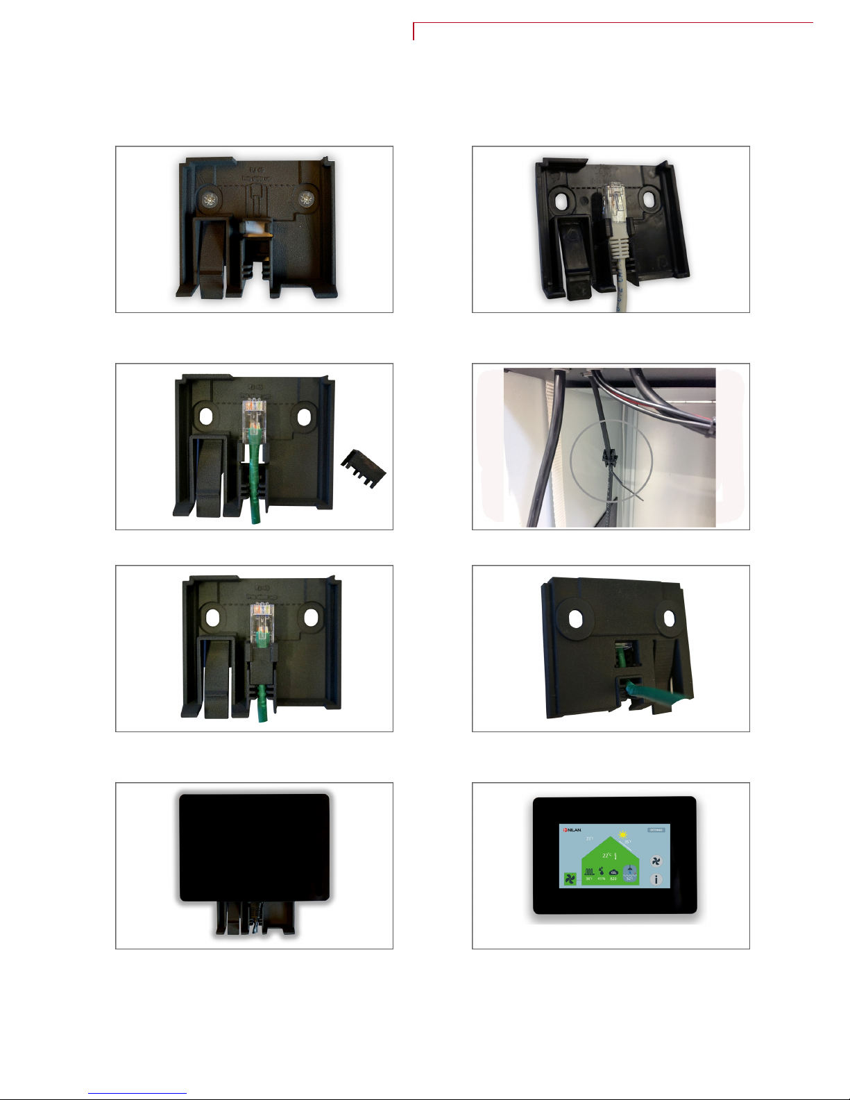
Wall fittings
T
he touch panel should be mounted on the wall with the integral wall fittings, and the cable form the
unit is mounted here too.
1. The wall bracket is fixed to the wall with two screws. 2.a. The RJ45 plug is mounted in the wall fitting with the
the top of the plug flush with the dotted line in the wall
fitting, and with the RJ45 trigger pin away from the wall.
2.b. You can fit the RJ45 plug to the cable you make
y
ourself. A spacer is supplied for this purpose.
The specer is fastened to the LAN-cable which is located
behind the large door.
2.c. The top of the plug must be flush with the dotted line
i
n the wall fitting. The spacer fits between the plug and
cable relief bracket.
3. The cable may be led down from the wall fitting or into
a
hole in the wall behind it.
4. Push the touch panel down over the wall bracket until a
c
lick is heard.
The panel may be removed from the wall by pressing the
locking clip.
5. The touch panel is ready for use.
Compact P / Compact P Polar - GEO (English)
BY NILAN
19

Electrical connections unit
S
afety
ATTENTION
A
ll work must be carried out by qualified personnel and in accordance with applicable legislation
and regulations.
ATTENTION
I
t is important that power is disconnected when working with the unit's electrical components.
It is important to check that cables have not been damaged or trapped during connection and use.
Compact P
Ventil ation an d domesti c hot wa ter
230V H z max 13 A (Schuko plug)
(Polar version 16A)
Safety switch
20

GEO3
Heat p ump for central h eating
Standa rd:
2 x 40 0V, 2L+N +PE, 13A, 50 Hz
Option 1:
Safety switch
3 x 23 0V, 3L+P E, 13A, 5 0 Hz
Option 2:
1 x 23 0V, L+N+ PE, 20A, 50 Hz
GEO6
Heat p ump for central h eating
400/23 0V, 2L+N +PE, 16A, 50 Hz
Safety switch
Compact P / Compact P Polar - GEO (English)
BY NILAN
21

Electrical connections accessories
E
xternal electrical preheating element
If Compact P has not been purchased in the Polar version with integral preheating element, there is an
option for purchasing an external electrical preheating element for subsequent installation.
The electric preheating element is mounted in the outdoor air duct before the unit with the necessary
temperature sensor, and connected to an external power supply.
1x230V ~ 50 Hz max. 16A
7 8
Min. 32 cm
T8
ATTENTION
I
t is important that the temperature sensor for the heating element is positioned at least 32 cm
after the preheating element in order to achieve correct regulation.
The T8 outdoor air temperature sensor is positioned before the external preheating element and
c
onnected to the Compact P control system, to allow it to perform regulation via the outdoor air
temperature. If it is not wished to regulate the functions via the outdoor air temperature, T8 may be
deactivated in the software under the frost protection section:
The preheating element has a three-stage safety system against overheating.
1
. There is a operating thermostat which regulates the heat and ensures that the supply air
temperature does not fall below -1 °C
2. There is a max. thermostat, which shuts down the preheating element if the temperature rises
above 50 °C
3. There is a manual safety thermostat, which shuts down the preheating element if the
temperature rises above 100 °C
ATTENTION
When mounting the electric preheating element, there must be a safety gap of minimum 15 cm
from any flammable material. The heating element must be insulated with a fire retardant
insulation material, but the cover on the connection box must not be insulated.
A dimensional drawing is available under the section on the electric heating element.
22

Electric heating element
I
f it is wished to control the supply air temperature, it will be necessary to fit a heating element.
An electric heating element can be purchased for fitting in the supply air duct (inlet air), and comes with
the necessary sensor and connection to the unit.
0-10V
GND
1x230V ~ 50 Hz max. 16A
Min. 50 cm
T7
0-10V
GND
T7
Wiring diagrams are supplied with the products. The heating element is set on the display under menu
o
ption: Ventilation/Heating element.
The wires are led alongside the duct and drawn through the bushing on top of the Compact P, led down
to the circuit board and mounted in accordance with the wiring diagram.
ATTENTION
W
hen mounting the electric heating element, there must be a safety gap of minimum 15 cm
from any flammable material. The heating element must be insulated with a fire retardant
insulation material, but the lid on the connection box must not be insulated.
Dimensional drawing:
Ø160
Positi oning opt ions:
Water comfort heater
I
f it is wished to control the supply air temperature, it will be necessary to fit a heating element.
Compact P / Compact P Polar - GEO (English)
BY NILAN
23

A water heating element can be purchased for fitting in the supply air duct, and comes with the
n
ecessary sensor and connection to the unit.
Connecting the sensors
Min. 50 cm
T7
T7
T9
T9
B44
B44
21 24
T7: Temperature sensor - T9: Temperature sensor heating element - B44: Frost protection
ATTENTION
W
hen B44 frost protection is mounted, the jumper in the same connections is removed.
The wires are led alongside the duct and drawn through the bushing on the top of the Compact P, led
d
own to the circuit board and mounted in accordance with the wiring diagram. The heating element
settings can be found on the display under menu option: Ventilation / Heating element.
24

Electrical connection for 2-way valve
1
1.
A 24V autotransformer is supplied and should be installed in a suitable position in the unit.
ATTENTION
T
he valve must not be connected to a 230V power supply
The wires are led alongside the duct and drawn through the bushing on the top of the Compact P, led
down to the circuit board and mounted in accordance with the wiring diagram.
Dimensional drawing:
83
310
440
Ø 125/160
238
22
32
31
300
3/4" RG
3/4" RG
Compact P / Compact P Polar - GEO (English)
BY NILAN
25

CO2
sensor
It is possible to purchase a CO2 sensor as an accessory if it is wished to control the ventilation level via
the CO2level in the dwelling.
The CO2 sensor is positioned in the extract air from the dwelling, and mounted on the beam with the
screws supplied:
The wire from the CO2sensor is led to the circuit board and connected as shown below:
The three wires are connected as follows:
G
ND: Blue
Out: Black
24V Brown
26

Cooker hood and EM box
T
here are several benefits from connecting the cooker hood to the dwelling's ventilation system.
Firstly, there is full heat recovery of heat from cooking.
Secondly, the unit is able to provide balance in the ventilation. If the cooker hood does not run via the
ventilation system and if the house is new and airtight, use of the cooker hood will create a
underpressure in the dwelling, minimising the suction effect from the cooker hood and also creating
smoke problems, for instance if a wood-burning stove or open fire is installed and in use. By running the
cooker hood via the ventilation system, the unit can increase the supply air as the volume of extract air
from cooker hood operation goes up. In this way, a balance can be maintained in the dwelling, and the
cooker hood will retain its full suction power.
In the case of ventilation of a large dwelling/building, with more than one bathroom, there may be
problems creating sufficient air capacity for the cooker hood. In these cases, an EM box will be an ideal
addition, as it minimises the extract air from the other high-humidity rooms for the short period that
the cooker hood is in use, and in this way ensures sufficient air for extraction via the cooker hood.
ATTENTION
I
f the cooker hood is connected to the ventilation system, it is important that it is fitted with a
good grease filter and that this can be regularly cleaned.
User selection 1
User selection 2
EM box
The potential free contact for the cooker hood is connected to User selection 1 or 2, which are
p
rogrammed in the unit's software under the section General settings. User selection 2 is chosen if an
EM box is to be installed.
Compact P / Compact P Polar - GEO (English)
BY NILAN
27

Other electrical connections
U
ser selection 1
It is possible to override the unit's functions via an external signal from a potential free contact.
The User selection function can be used for many purposes, e.g. in the case of a wood burning stove or
open fire. Initial settings of the ventilation system set up a small underpressure, so that humidity in the
air is not forced into building parts. This is naturally a disadvantage when lighting a wood burning stove,
as smoke will enter the room. By means of an potential free contact, one of the fan speeds, e.g. fan
speed 4, can be set to run with a slight overpressure instead, so the smoke goes up the chimney as it
should.
Connection to CTS700 control system:
Potential free contact
User selection 1 is programmed in the unit's software under General settings. See the options in the
S
oftware instructions.
28

User selection 2
A
s with User selection 1, it is also possible with User selection 2 to override the unit's functions via an
external signal from a potential free contact. The difference is that by activating User selection 2, the
control system also transmits an output signal.
User selection 2 has the higher priority and is therefore used for cooker hood operation if a cooker
hood is connected to the ventilation system. Normally fan speeds 3 or 4 are set for cooker hood
operation. The output signal can be used for connecting an EM box or external damper which is to
assume a particular setting during cooker hood operation.
There are many other uses for User selection 2 which we shall not discuss further in these instructions.
Connections:
Potent ial free contact
Output signal
Compact P / Compact P Polar - GEO (English)
BY NILAN
29

External room temperature sensor
D
o you not want to control the unit according to a room temperature measured through the T3 extract
air, an external room temperature sensor can be connected..
The room temperature sensor is placed in the room, which should be the reference for the house.
Fire protection
A
fire thermostat or external fire automatic can be connected. It must be a joined signal, when it is
broken the Compact P register it as a fire and stop the unit.
Note! If the unit is connected to external fire automatic, you set the software: General Settings/
S
ervice/Auto reset for external fire alarm to "On".
30

Common alarm
I
f the unit is located in a place where access is poor or infrequent, and if the control panel is also located
here, it may be hard to observe any alarms.
An external alarm in the form of a light or acoustic signal, etc., can be connected to the unit.
External heat supply
C
ompact P is able to control an external room heating such as electric radiators or a floor heating
system.
The room temperature is monitored by the Compact P, which block the external heating supply when
there is no need for heating. If Compact P cannot achieve the desired room temperature through the
ventilation, the external heating supply is released until the room temperature is in the desired level.
The external heat supply is connected via relay 8, and set in the touch-display under the menu:
Ventilation-/Temperature regulation
A maximum effect of 500W can be connected (Compact P Polar need to have a transfer relay mounted).
Compact P / Compact P Polar - GEO (English)
BY NILAN
31

Connecting EHD damper
T
o conduct outdoor air down through a geothermal pipe in the ground makes good sense. The air is
heated during the winter and cooled in the summer by the ground.
But passing outdoor air through such a geothermal system may not be the best idea in the spring and
autumn, but taking it directly through a roof vent is recommended.
The CTS700 control system has a built-in function that measures whether the geothermal pipe or roof
vent provides the best option for air intake.
It measures the outdoor temperature during a stabilising period from the geothermal pipe and roof
vent respectively. The measurement indicates where it is best to direct the outdoor air. CTS700 sets
the EHD damper to the best option, and continues ventilation for a set period, referred to in the
program as holding time.
The EHD damper is connected via relay 7 and set on the display menu item: Ventilation / Frost
protection or de-icing / Frost protection.
EHD
ATTENTION
D
amper, geothermal pipe and roof vent are not supplied by Nilan.
ATTENTION
W
hen using a geothermal pipe, the "Low ventilation a low outdoor temperature" feature cannot
be used.
32

BAH Geothermal heater
A
geometric preheater has two functions:
1. It acts as frost protection in the winter, heating up the outdoor air and protecting the unit against
icing up
2. It can then be used to cool down outdoor air in the summer, supplying cooled air to the home
The heater is set on the display under: Ventilation/frost-protection or de-icing
11
12
14
14
13
12
12
19
1517
18
16
T8
Pdiff.
19
18
T8
11. Condensation drain
1
2. Shut-off valves
13. Particle filter
14. Filling and drain cocks
15. Safety valve
16. Bleed screw
17. Expansion tank
18. Pressostat
19. Circulation pump
T8. Outdoor temperature sensor
ATTENTION
C
irculation pump, heater and brine circuit are not supplied by Nilan.
Compact P / Compact P Polar - GEO (English)
BY NILAN
33

Passive cooling function
G
EO has a passive cooling function. It works by the soil which cools the temperature of the brine, the
cold brine water used to cool the water in the central heating floor system or led to a fan coil.
Passive cooling by the floor heating system
An external temperature sensor is connected to digital input 10. When the contact is switched on GEO
goes into passive cooling, where the circulation pump for the brine circuit and the circulation pump for
the central heating are running. The relay output 10 is activated and turns a tree-way-valve, so the
brine water is led to the passive heat exchanger (not a Nilan delivery). When the contact is switched off
again, GEO will go back to normal operation.
The external temperature sensor is often equipped with an infrared sensor, which measures the floor
temperature and stop the cooling before, dew is formed on the floor.
+
+
+
+
+
T18
T17T13
T14
T16
T21
T22
If there is a need that GEO must produce domestic hot water, the passive cooling is stopped.
+
+
+
+
+
T18
T17T13
T14
T16
T21
T22
34

Passive cooling by fan coils
A
n external temperature sensor is connected to digital input 10. When the contact is switched on GEO
goes into passive cooling, where the circulation pump for the brine circuit are running. The relay output
10 is activated and turns a tree-way-valve, so the brine water is led tod the fan coil (the fan coil is not a
Nilan delivery). When the contact is switched off again, GEO will go back to normal operation.
+
+
+
+
+
T18
T17T13
T14
T16
T21
T22
If there is a need that GEO must produce domestic hot water, the passive cooling will still be running,
e
ven with higher effect, because the brine water will be cooled by the heat pump, when it is producing
domestic hot water.
+
+
+
+
+
T18
T17T13
T14
T16
T21
T22
Compact P / Compact P Polar - GEO (English)
BY NILAN
35

Plumbing installation
Condensate drain
Important information
C
ompact P is supplied with a reinforced 20 mm condensation drain pipe with built-in water lock.
ATTENTION
I
nstall the condensation drain with an even slope of minimum 1 cm per metre to the nearest
drain. The overflow from the safety valve to the cold water supply must be piped to a visible
drain.
ATTENTION
I
f the unit is placed outside the building, the condensation drain must be protected against icing
up. The fitter is responsible for ensuring that the unit is protected from freezing.
The connection of the water lock must be airtight to prevent air being sucked into the unit, trapping
c
ondensation in the unit. Ehen the condensation overflows the tray and runs out of the unit, damages
must be expected.
After fitting the water trap, you must test the function in the following way: Fill the condensate tray
with water. Start up the unit at highest fans speed, and allow it to run for several minutes. After that
control that no water is left in the condensation tray (the unit must be connected to the duct system,
and the lid must be on during the test).
The water trap can dry out, preventing water to run out from the unit condensation tray. Control the
water trap in regular intervals, especially after the summer and top up with water if needed.
The water trap is integrated in the pipe running from the condensation tray to the drain.
36

Domestic hot water tank
C
onnection overview
Compact P front
310
110 248
200
240
1
2
3
5
4
Compact P back
C
onnections:
1. Connection for 3/4” circulation pipe
2. Hot water outlet 3/4"
3. Cold water intake 3/4"
4. Return supplementary coil 3/4"
5. Supply supplementary coil 3/4"
Supplementary coil is only standard on Compact P SOL models.
The coil is located in the bottom, and has an external diameter of 22 mm and is 8,500 mm long,
equivalent to 0.6 m 2 .
Connection
ATTENTION
A
ll work must be performed by qualified personnel and in accordance with relevant legislation
and provisions.
Nilan's hot water tanks are double-enamelled, ensuring long life. The efficient foam insulation protects
a
gainst unnecessary heat loss.
All connection nozzles for water have 3/4" thread and are located in the tank bottom.
The tank is also fitted with an electronically-monitored sacrificial anode that automatically displays a
warning on the display when it needs changing.
Compact P / Compact P Polar - GEO (English)
BY NILAN
37
CAUTION
C
hanging the anode when notified on the display is important. Failure to do so can cancel the
guarantee on the hot water tank.
The tank is fitted with a 1.5 kW supplementary electrical heater deactivated by default and activated
v
ia the control panel if required.
ATTENTION
T
he supplementary heating must not be activated before the water tank is full of water.
Hot water circulation
I
f wished, hot water circulation can be established by fitting a non-return valve and a circulation pump
for domestic water to the tank's circulation connector (1).
If hot water circulation is not established, the connector must remain closed with the factory-mounted
shut-off plug.
ATTENTION
H
ot water circulation can lead to a significant heat loss in the pipes, diverting a good proportion
of the heat pump's output. To avoid this, circulation pipes and the hot water loop must be
insulated with at least 30 mm mineral wool.
It is advisable to set a timer so that the circulation pump is not running constantly.
Solar coil
A
ll Compact P SOL models have integral supplementary coil, see connections list.
The solar coil with a surface area of 0.6 m2 is intended for solar heating systems, though it can also be
connected to other heat sources.
ATTENTION
I
f a solar collector or other heat source is connected to a Compact P model, it is recommended
that a safety group is connected to the hot water outlet to secure against scalding.
Softened water
I
f it is wished to soften water with salt in a Nilan hot water tank, the following must be observed:
• The hardness of the water must be at least -2° dh (proportion of alkaline earths 0,4 mmol/l)
• The conductivity must be between 13 mS/m og 150 mS/m (millisiemens per m)
• The pH value must be between 6.5 and 9.5
• The chlorine content must be under 250 mg Cl/l
If the above criteria are exceeded, the anode current will be too high, the anode will break down too
quickly and the water will begin to smell bad.
CAUTION
D
emineralised water (double ion exchange) must not be used as the tank will corrode very
rapidly. Demineralised water is also called totally desalinated water and deionised water.
38

Central heating
W
ater connection list
4
3
21
1. Supply flow central heating
2. Return flow central heating
3. Supply flow brine (from ground hose)
4. Return flow brine (to ground hose)
Compact P / Compact P Polar - GEO (English)
BY NILAN
39

Brine circuit
A
fter completed and demonstrated leak testing, brine can be filled. Filling the brine should be
performed by a qualified installer.
It is recommended to buy ready-mixed brine with corrosion inhibitors. If you mix the brine by yourself,
the water quality must be suitable for brine.
CAUTION
E
nsure that the brine hoses are deflated and without dirt, befor the brine is connected to the
heat pump.
Isolation of the brine tubes
A
ll pipes to and from the ground collectors / geothermal circuit must be isolated completely into the
heat pump, to prevent condensation on the cold tubes.
A collection tray must be established for condensation water from the heat pump and water from the
safety valve.
Safety for the brine system
The brine hoses is equipped with a pressure control which make an alarm by falling pressure in the
ground hoses. The alarm is triggered, if the pressure falls below 0,6 bar. The unit is turned of and
cannot start up again automatically.
The ground hose system must be designed as a closed system with a pressure at rest of 1,5 - 2,5 bar.
40

Check list for the central heating system prior to start-up
T
he check list is used when starting and delivering the system, and it should always be filled in. See the
other sections in the manual for further information.
Electrical connection and controls Checked - date Notes
The power supply is connected and secured in
a
ccordance with the wiring diagram and manual
The control panel is installed in a place that can
e
asilybe seen by the user
Central heating circuit Checked - date Notes
The central heating circuit is sealed
The central heating circuit has been vented after filling
Central heating circuit pressure, overpressure Bar
The opening pressure for the central heating circuit´s
s
afety valve is correct
The circulation pump is rated correctly for the
i
nstallation
The circulation pump is in constant operation or is
c
ontrolled by the heating pump
Brine circuit Checked - date Notes
Brine circuit / ground hoses is sealed
Brine type
Brine concentration % %
Freezing point (recommended -20 °C to -18 °C) °C
The brine is mixed thoroughly before filling
The brine circuit is vented after filling
Pressure of brine circuit bar
Fluid from the safety valve for the brine circuit cannot
r
un into the sewer
The brine circuit is connected correctly to the heat
p
ump (the heat pump can be damaged by wrong
connection)
Design flow brine circuit m3/h
Adjusted flow brine circuit m3/
h
There is a risk of low pressure and frost damage of evaporator in the heat pump, if the conditions for
t
he brine circuit is not met.
Compact P / Compact P Polar - GEO (English)
BY NILAN
41

Plumbing connections for accessories
S
afety group
CAUTION
A
safety device must be connected to the hot water tank.
When water is heated to 60 °C, it expands by 2%. A pressure tank could burst without a safety valve
k
eeping excess water out. The safety valve should therefore drip during warming up.
Installation:
The following should be remembered during installation:
a
.
The double nut is attached to the water heater’s cold water
pipe so that the arrows are pointing in towards the water
heater (in the direction of the flow). The joint with the water
heater is sealed using a threaded washer.
b.
The joint between the double nut and the system is sealed
using fibre packing.
c.
The rubber ring seal (the O-ring) is fitted to the unit so that it
can function as a seal between the safety valve and the unit in
such a way that the valve is locked.
The end of the overflow pipe must be visible, and it must be able to run out safely via the drain.
ATTENTION
A
s water expands as it heats up, the safety valve will drip.
ATTENTION
It is up to the installation engineer to tell the customer where the safety valve is and how it
works, and also that it must be regularly checked at least twice a year in order to prevent
incrustation.
42

Safety group with anti-scald protection
T
he control system contains as standard a temperature limit for domestic hot water of 65 ºC. This
setting prevents users from scalding themselves when the hot tap is turned on.
It also means that when Compact P is in cooling mode, cooling will stop when the domestic hot water
reaches a temperature of 65 ºC.
If the cooling requirement is higher than this, the temperature limit may be raised to 80 ºC, but in this
case an anti-scald device must be mounted under the hot water tank, to prevent users from scalding
themselves when turning on the hot tap.
The anti-scald device mixes hot water with cold water, thus bringing down the temperature and
avoiding scalding. This will extend the period for which Compact P can perform cooling.
CAUTION
I
f a solar panel is connected to the hot water tank, an anti-scald device must be mounted.
1
2
3
4
5
6
7
8
1. Hot water from the hot water tank
2
. Cold water to the hot water tank
3. Stop cock cold water
4. Pressure relief valve (6 bar or 10 bar)
5. The overflows from the safety valve are led to a prominent drain
6. Cold water supply
7. Domestic hot water for the dwelling
8. Mixing valve for domestic hot water for the dwelling (can be set between 35 - 60 ºC)
Compact P / Compact P Polar - GEO (English)
BY NILAN
43

Hot water heater (accessory)
CAUTION
Connection of the hot water heating element must be carried out by an authorised plumber.
CAUTION
I
f the control unit is installed outdoors or external to the building, it must be protected against
frost.
The heater is for duct connection, and cannot be integrated into the control unit.
T
he heater is supplied as an accessory and consists of: Heating element with temperature sensor T9
and frost thermostat B3, actuator, regulator valve and autotransformer.
Must be activated via the control system.
The system should be connected, bled and checked for leaks. The system can then be started. Check
and clean the sediment trap after flushing the system appropriately.
4
2
3
1
Supply
Return
1. Water heater
2
. Actuator and regulation valve: Danfoss AME 140/24V 0-10V signal, 2-way valve VZ2 Kv0,4
(supplied by Nilan) Kvs-value MUST be checked compared to the supply.
Differential pressure: 0.1-0.6 bar
At a supply temperature of 60°C, a cooling effect of 20°C over the heater is calculated at maximum
heat output.
3. Bleed valve (not supplied by Nilan)
4. Snavsopsamler (ikke Nilan leverance)
44

IMPORTANT, concerning Danfoss Actuator type AME 140:
M
andatory procedure for refitting the actuator:
1. Disconnect from mains electricity. Remove actuator cover.
2. Disengage the gear by holding the button under the housing in while screwing the spindle upwards
as far as it will go (counter-clockwise)
3. Fit actuator and reconnect mains electricity.
4. Switch DIP switch no. 1 to ON and then OFF.
5. Automatic calibration will run for up to 6 minutes.
(The diode will flash during calibration before becoming constant).
6. Fit actuator cover.
Output chart, hot water heater
Water side Air si de
[°C] [m3/h] [kPa] [kW] [m3/h] [°C] [°C] [Pa]
40/30
0,04 0,85 0,52 100 16 31,1 2
0,06 1,25 0,64 135 16 29,8 3
0,08 2,18 0,87 210 16 28,1 6
0,11 4,65 1,32 400 16 25,7 17
0,17 9,62 1,98 800 16 23,2 53
0,19 11,9 2,23 1000 16 22,5 77
60/40
0,04 0,69 0,94 100 16 43,5 2
0,05 1,00 1,16 135 16 41,1 3
0,07 1,75 1,58 210 16 38,0 6
0,10 3,70 2,40 400 16 33,5 17
0,16 7,66 3,58 800 16 29,1 53
0,18 9,48 4,03 1000 16 27,8 77
70/40
0,03 0,40 1,06 100 16 47,0 2
0,04 0,58 1,30 135 16 44,2 3
0,05 1,00 1,76 210 16 40,5 6
0,08 2,09 2,64 400 16 35,3 17
0,11 4,25 3,9 800 16 30,3 53
0,13 5,24 4,38 1000 16 28,8 77
Temper ature
supply /return
Flow Pressu re loss Output Air v olume Temper ature
before HWH*
Temper ature
after HWH*
Pressu re loss
over H WH*
*(HWH) hot water heater
Compact P / Compact P Polar - GEO (English)
BY NILAN
45

Domestic hot water tank
T
he GEO unit can be connected to an external hot water tank (SHW) and to the hot water tank in the
Compact P (DHW). A three-way valve, which can be purchased as an accessory, is required.
PTL PTH
1
2
8
9
10
~
11
11
3
4
5
7
25
19
18
17
16
PZAL
20
18
44
14
28
13
14
15
14
40
35
6
B
AB
35
B
A
46
12
12
18
14
15
14
13
13
41
22
23
21
22
23
21
24
42
43
45
26
27
27
17
36
Everything with in the red box is in the Nilan delivery included.
1. Evaporator
2
. Service valve for low pressure
3. Low-pressure presostat
4. Compressor
5. High-pressure pressostat
6. Condenser
7. Expansion valve
8. Sight glass with humidity indicator
9. Service valve for high pressure
10. Combi filter
11. Connection 1"
12. Flexihose 1"
13. Feed tab
14. Shut-off valve
15. Dirt filter
16. Safety valve 3,5 bar
17. Manometer (for the central heating, not mounted)
18. Ball valve
19. Circulation pump 130 mm
2
0. Pressure control 0,5/1,1 bar21. Flexihose 10 mm
22. Expansion tank 8 L
23. Automatic control vent 3/8"
24. Electric cartridge 2 kW
25. Temperature sensor T18
26. Safety valve 2,5 bar (not mounted)
27. Connection 3/4"
28. Over current valve
35. Three way valve
36. Circulation pump
40. Temperature sensor T13
41. Temperature sensor T14
42. Temperature sensor T16
43. Temperature sensor T17
44. Temperature sensor T21 (top SHW tank)
45. Temperature sensor T22 (bottom SHW tank)
46. Outdoor temperature sensor T20
46

Connecting to SHW hot water
T
he cold water form the domestic supply is pre-heated in the GEO heat pump´s SHW tank to 45 ºC
(factory setting 40 ºC), after which it is fed to the DHW tank in the Compact P, where it is heated to the
desired flow temperature.
76
1
2
3
4
5
GEO se en from the front GEO se en from below D HW tank SHW ta nk
1. Supply flow to the solar coil in the SHW tank from GEO heat pump (the three-way-valve ist not
m
ounted from factory)
2. Return flow from the solar coil in the SHW tank to GEO heat pump
3. Connection for domestic cold water supply
4. Supply flow af pre-heated domestic hot water from the SHW tank to the DHW tank in Compact P
5. Supply flow of domestic hot water from the DHW tank
6. Connection for hot water circulation
7. Sensor pocket
Connecting to DHW hot water
If the demand for domestic hot water is so great that the Compact P unit´s heat pump cannot cope, the
GEO heat pump can be connected to the DHW tank´s solar coil to help heating up the domestic hot
water
1
2
3
4
GEO se en from the front GEO se en from below D HW tank
1. Supply flow to the solar coil in the DHW tank from GEO heat pump (three-way-valve as accessories)
2. Return flow from the solar coil in the DHW tank to GEO heat pump
3. Connection for domestic cold water supply
4. Supply flow of domestic hot water from the DHW tank
Compact P / Compact P Polar - GEO (English)
BY NILAN
47

Ventilation mounting
Duct system
Legislation
ATTENTION
A
ll work must be carried out by qualified personnel and in accordance with applicable legislation
and regulations.
Ducts
T
here are two systems for transporting air round the building.
Spiral tubes
Spiral tubes are metal ducts which are cut to size with an angle grinder, screwed together with bends
and manifolds and laid out in accordance with the working drawing. The duct pipes are typically laid at
the rafter ends and fixed with perforated band or suspended with suspension band. Avoid unnecessary
bends in the ducting.
To avoid noise transmission, where sound is transmitted from room to room, a sound damper must be
mounted in each room.
The ducts must be insulated to avoid heat loss and condensation. In some cases this can be avoided if
the ducts are led through the ordinary insulation or inside the climate screen.
NilAIR tubes
NilAIR tubes are a flexible system which is easy to mount. The tubes are easily cut to size with a hobby
knife and laid according to the working drawing without use of bends and manifolds. A manifold box is
installed after the unit and the tubes run from this out to the various rooms.
With NilAIR tubes it is unnecessary to mount sound dampers in each room, as there is no risk of noise
transmission.
If the tubes are led outside the climate screen they must be insulated to avoid heat loss and
condensation. This is easier than with spiral tubing, as NilAIR tubes are easier to lead through ordinary
insulation.
NilAIR tubes are more flexible than spiral tubing and can therefore be laid in places where ordinary
spiral tubing would be impossible.
Unit
Nilan recommends mounting a flexible connection between the unit and the duct system.
This is to avoid oscillations from the unit being transmitted to the duct system, but also to ease future
servicing where it is necessary to move the unit.
Nilan offers flexible silicing, which, apart from providing a flexible connection between the unit and the
duct system, also dampen the passage of sound from the unit to the duct system.
Flexible silencing are insulated for condensation, but it may be necessary to insulate them further to
meet local requirements for duct system insulation.
48

Extract air
E
xhaust valves are mounted in the moisture-generating rooms and strategically placed where they can
extract the moisture air most effectively.
Moisture-generating rooms:
• Bathroom
• Toilet
• Kitchen
• Utility room
Supply air
Supply air valves are mounted in habitable rooms and strategically positioned to give the minimum
annoyance. For example, it is not recommended to mount incoming air valves over areas where people
sit, as the air in some cases can be perceived as a draught.
Habitable rooms:
• Living room
• Kitchen-living room
• Bedroom
• Office
Roof stack
The roof inlet and outlet must be positioned and designed to limit pressure fluctuations in the
ventilation system caused by wind impact, and also to prevent access by birds and other animals, and
to ensure that the inlet and closed duct system are kept free of plant parts and foreign objects.
The air inlet must be located to minimise the risk of short-circuiting from the discharge air, having
regard to the prevailing wind direction.
The air inlet should be placed a minimum of 0.5 m above the roof surface, but a minimum of 1 m over
flat black roofs up to the underside of the inlet, to ensure that warm air is not drawn into the building in
the summer. The air inlet should be located on the north or east sides of pitched roofs.
Sound damping should also be mounted between the unit and roof stacks to avoid noise annoyance to
neighbours.
Compact P / Compact P Polar - GEO (English)
BY NILAN
49

Initial regulation
I
mportant information
ATTENTION
F
or the ventilation system to operate optimally, it is important that initial regulation is carried
out correctly. We recommend having this done by experts.
It is important to measure the total supply (inlet) air and extract (outlet) air. The system must
have a minimum vacuum, i.e. it must draw in more air out than in, to avoid humidity being
pressed into the building construction.
Initial regulation connectors
T
he unit has initial regulation connectors for measuring the supply air (inlet air) and extract air (outlet
air) volumes.
The graph can be used for roughly setting the main air volume for dry operation without condensation
precipitation, and with approximately the same temperature for outdoor air and extract air.
On the extract air side (outlet air), the pressure drop dP4-3 [Pa] is measured between the connectors
labelled 3 and 4. The air volume qv [m3/h] is read off on the graph.
On the supply air side (inlet air), the pressure drop dP2-1 [Pa] is measured between the connectors
labelled 1 and 2. The air volume qv [m3/h] is read off on the graph.
ATTENTION
T
he capacity in the pressure drop diagram is based on a dry heat exchanger.
Pressure fall diagram
2
4
1
3
The measuring connectors are inside behind the
t
op front panel.
50

Start-up
Central heating
Filling with water
ATTENTION
B
efore starting the heat pump and the circulation pump, the central heating circuit must be
filled with water
Fill central heating circuit with water via the feed tap until the correct water pressure is obtained. It is
i
mportant that all circuits in the central heating system are open during filling.
ATTENTION
O
rdinary water or all common types of antifreeze can be used
There is an automatic vent fitted, which is activated wen filling with water. Check that the cover on the
vent is loose.
Once the central heating circuit has been filled to the correct water pressure, the circulation and heat
pump can be started.
Topping up water
The water pressure must be carefully checked the first few days, even several times a day. It may be
necessary to top up the water in the central heating circuit if the water pressure has dropped.
ATTENTION
I
t is important that the circulation and heating pump is switched off while topping up the water
The water pressure will stabilise after a few days, after which the checks can be reduced to once a
month.
ATTENTION
I
f the central heating circuit requires topping up after the start-up phase, it should be checked
for leaks
Check the particle filter
T
here may be some particulate matter in the central heating circuit, and the heating pump must be
checked immediately after being put into operation.
The filter must be checked several times a day just after installation until it stays clean. With normal
operation, it is enough to check the filter twice a year.
Cleaning the particle filter:
1. Switch off the heating pump on the control panel (Settings: Central heating / Standby functions /
Turn off central heating)
2. Turn the shut-off valve to close off the circulation
3. Remove the filter and rinse until clean
4. Replace the filter
5. Turn the shut-off valve to open up the circulation
6. Switch the heating pump back on
Compact P / Compact P Polar - GEO (English)
BY NILAN
51

Troubleshooting
Emergency operation
Emergency operation domestic hot water
I
f an error occurs in the controller or components in the Compact P, and the unit therefore stops, it will
not be able to produce domestic hot water.
If the installer is not able to come right away or the error happens outside the opening hours, and you
therefore cannot contact the installer, there is a possibility to get hot water by setting the unit into
emergency mode.
The bu tton for the emer gency op eration a re locat ed behind the larg e door
The emergency operation has three settings:
I
- Auto: El-supplementation is controlled by the control in the unit
(standard setting)
0 - Off: El-supplementation is off and cannot be turned on again by
the control in the unit
II - Manuel: El-supplementation is turned on, and cannot be turned
off by the control in the unit (Don´t turn it on if there is no water in
the tank)
CAUTION
In manual operation, the water temperature can achieve 75 °C, which can cause scalding, if you
are not careful when you open the hot water.
52
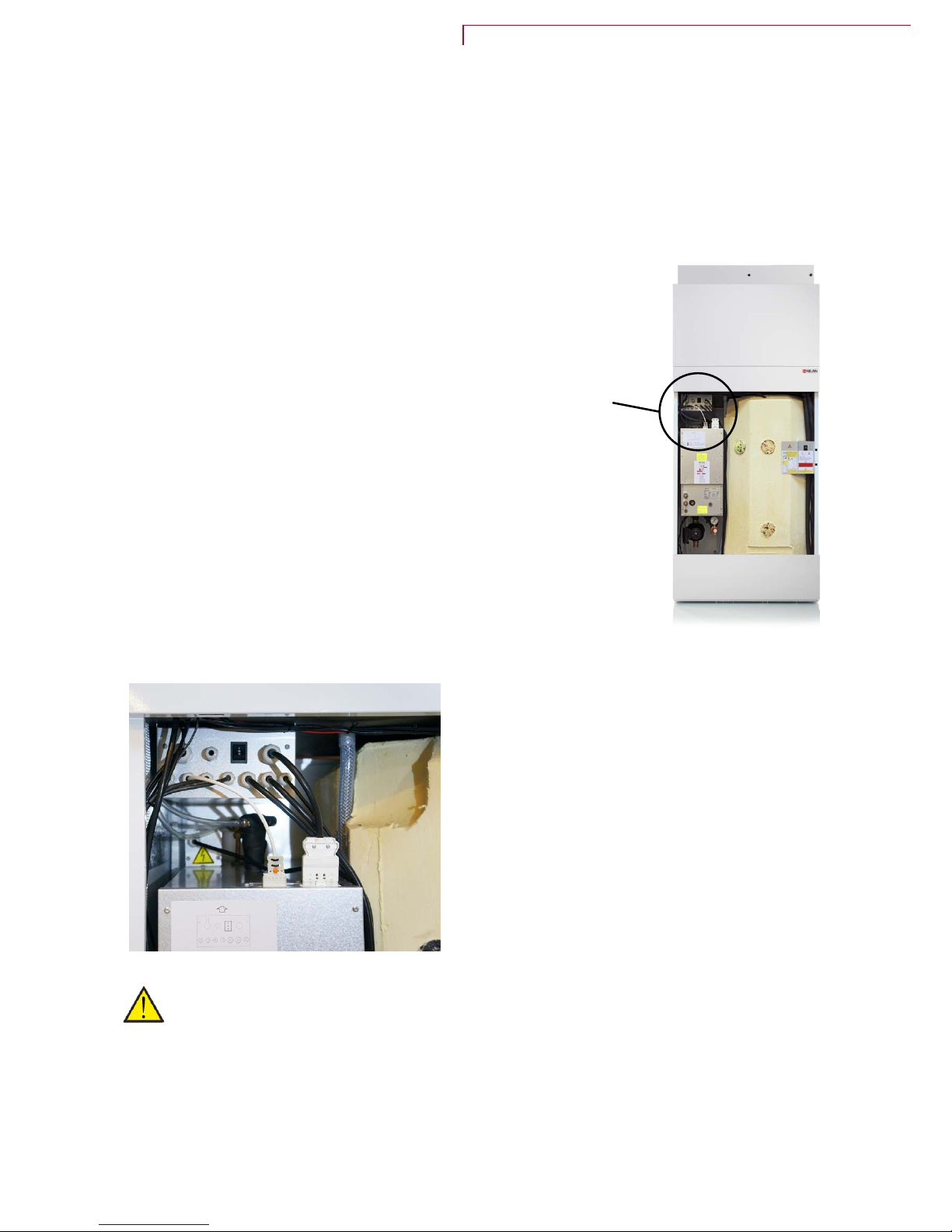
Emergency operation central heating
I
f an error occurs in the controller or components in the GEO heat pump, and the heat pump therefore
stops, it will not be able to heat up the house by the central heating.
If the installer is not able to come right away or the error happens outside the opening hours, and you
therefore cannot contact the installer, there is a possibililty to heat up the house by setting the heat
pump into emergency mode.
The button for the emergency operation is located behind the large door
The emergency operation has tree settings:
I
- Auto: El-supplementation and circulation pump controlled by the
control in the unit (standard setting)
0 - Off: El-supplementation is off and cannot by turned on by the
control in the unit
II - Manuel: El-supplementation and circulation pump is on and
cannot be turned off by the control in the unit
ATTENTION
I
n manual operation the supply flow temperature for the central heating can achieve 40 °C.
Compact P / Compact P Polar - GEO (English)
BY NILAN
53

Domestic hot water
E
rrors and solutions domestic hot water
Proble m Possib le cause Soluti on
The un it produc es insuff icient do mestic hot water The fi lters may be block ed so tha t insuffic ient air
i
s reac hing the unit.
This c an occur if the fi lters are not chang ed
freque ntly enou gh.
This c an occur if the un it has be en operate d
during the buil ding proc ess and t he filters are
filled with dus t and dir t.
Change the filt ers and, if necess ary, chang e the
f
ilter change pe riod to a shorter interval.
54

Compact P / Compact P Polar - GEO (English)
BY NILAN
55

Nilan A/S
Nilanvej 2
DK-8722 Hedensted
Tlf. +45 76 75 25 00
Fax +45 76 75 25 25
nilan@nilan.dk
www.nilan.dk
United Kingdom:
S L Services
25 St Leonards Road, Horsham
RH13 6EH West Sussex
Tlf. +44 (0) 7919 444452
stuart315@aol.com
www.nilanuk.com
Ireland:
Nilan Ireland
Ballylahive, Abbeydorney
Tlf. +353 (0) 87 9798361
maurice@nilan.ie
www.nilanireland.ie
Document no.M32_Compact-P-GEO_DK
Nilan A/S disclaims all liability for errors and omissions in printed instructions - and for loss, damage or injury arising from the published material, whether this is due to errors or
inappropriate information in the material or other causes. Nilan A/S reserves the right to make changes to products and instructions without prior warning. All trademarks are the property of
Nilan A/S, and all rights are reserved.
 Loading...