


Version: 10.00, 13-04-2015
Software-version: 2.30
Installation instruction
CTS 602 by Nilan
Comfort 1200
Comfort 5000

Table of contents
Table of contents ............................................................................................................................ 2
Introduction ..................................................................................................................................... 3
Power supply .................................................................................................................................. 4
Assembly of Comfort ...................................................................................................................... 5
Condensation drain / water seal ..................................................................................................... 6
Heating surface, water .................................................................................................................... 7
Heating surface, electrical (retrofitting) ........................................................................................... 9
Activating the service menu ................................................................ ...................................... 10
Heating surface ......................................................................................................................... 11
Air quality .................................................................................................................................. 12
Air exchange ............................................................................................................................. 13
Defrost ...................................................................................................................................... 14
Temp. control ............................................................................................................................ 15
Inlet control ............................................................................................................................... 16
Room control ............................................................................................................................ 17
Re-start ..................................................................................................................................... 18
Preset ....................................................................................................................................... 19
Manual ...................................................................................................................................... 20
Modbus ..................................................................................................................................... 21
Datalog ..................................................................................................................................... 22
System dimensions ...................................................................................................................... 23
Accessories/spare parts ............................................................................................................... 25

Please control that the following documents have been delivered together with the unit:
- Directions for assembly & use (this document)
- CTS 600 directions
- Electrical chart
Introduction
Comfort is designed for heat recovery with air volumes up til1200m3 / h. The energy from the exhaust is recovered to the inlet via the counter flow heat exchanger, where the two air streams pass
each other without coming into direct contact.
The system is prepared for retrofitting of a post-heating element (electricity or water) for supply
heating of the inlet air. The post-heating element is controlled via CTS 602.
The system comes standard with filter class F5 on the extract air and F7 on the supply air.
Operating the unit is done with the CTS 602 control. The control has many functions such as menu
based attendance, week programme, time controlled filter guard and adjustment of the velocity of
the ventilator. (Directions for the CTS 602 control is described in another document delivered with
the unit.)
Comfort is delivered tested and ready for use. Installation and start-up must be carried out by an
authorized electrician.
Nilan reserves the right to alter these instructions without prior notice Page 3 af 25

Power supply including safety switch must be installed by an authorized electrician.
The Comfort-unit must be connected according to the attached electrical chart.
Power supply
The unit is delivered with 1m test cable for the CTS 602 panel. The panel should be connected to
the CTS 602 control in the unit with cable type 2x2x0.25mm2 twisted in pairs. (Maximum length
50m).
The CTS 602 panel must be placed dry and frost-proof. The panels’ integrated feeler prevents further cooling of the building if the primary heat-supply stops by stopping the ventilation if the panel
feeler gets below a specific value. (Factory setting is 10°C; the value can be set from 1-20°C.)
CTS 602 control
If a water heating element is installed in the system, the regulation vent must be connected electrically as described in the enclosed wiring diagrams.
Nilan reserves the right to alter these instructions without prior notice Page 4 af 25

When mounting the Comfort-unit future service and maintenance should be considered.
There is required a minimum of open space in front and behind of the unit of 60cm.
Comfort
1200/5000
4 x vibration absorbers
Assembly of Comfort
In order to ease the mounting each of the connection pieces is labeled. Please notice the labels.
The connection between the unit and the ducting should be a flexible transition.
The system must be level because of the condense outlet. The condense outlet requires a minimum clearance height of 125mm beneath the outlet connection.
The exchanger is low-noise and low-vibration. However, potential vibrations spreading from the
system to the individual building parts must be taken into account. To detach the system from the
floor, we recommend that the system is placed on vibration absorbers. The vibration absorbers
must be placed diagonally on each corner to ensure that the system does not “fall down” from
them. If a water heating element is installed in Comfort 300/450/600, a clearance distance of 60cm
is required behind the system.
It is not necessary to re-insulate the system as it is delivered with a 20mm standard insulation.
Mounting the Comfort unit
Nilan reserves the right to alter these instructions without prior notice Page 5 af 25

The condensation drain should be carried with an even inclination of at least 1cm per
metre, frost-proof to the nearest outlet. The overflow from the safety valve should also be
carried to the nearest outlet.
To avoid frost problems it can be necessary to supply the condensation drain with a
heating cable. It is the plumbers’ responsibility to secure the drain. (See Accessories)
min. 112,5mm
min. 50mm.
min. 50mm.
Ø20mm drain
Comfort
The water seal should be tested as described below. (the unit must be connected to the
ducting and the front door should be closed):
Condensation drain / water seal
The Comfort unit is delivered with a 20mm condensation drain. (PVC, GF-fittings). The drain is
placed under the discharge.
When the system is running, there can be a vacuum of up to 500Pa (corresponding to 50mm water
column) in the outlet. For this reason, the difference in height in the water seal must be minimum
50mm.
The water seal can dry out and avoid the water from running out of the unit. Therefore the water
seal should be tested regularly and refilled with water if necessary. An elevated height of the water
seal will reduce the need for refilling with water.
Condensation drain / water seal
Nilan reserves the right to alter these instructions without prior notice Page 6 af 25

Connecting the heating surface must be done by an authorized plumber.
If the unit is placed outside or in a cold location the installation must frost secured.
To obtain a stable control of the heating surface, the distance between the mixing loop
and heating coil must not exceed 2 meters.
Avoid routing pipes in the system in such a way that the fan cannot be removed.
Air flow
Flow
Return
B3
T9
2
1
M
Heating surface
3
Note that the temperature sensor T9 and frost-protection B3 is placed at the heated side of the heating
surface close to the return connection. See electrical chart.
1:
Actuator and regulating valve:
Danfoss AME 140/24V, - 3-vejsventil VZ3 DN15 Kv0,63, (Nilan delivery)
2:
Circulation pump, eg. Grundfos UPS 25-40 or equivalent (not Nilan supply)
3:
Dirt-catcher (not Nilan delivery)
4:
Shutoff valve (not Nilan delivery)
5:
Exhaust (not Nilan delivery)
Connecting the heating surface, suggestion
Heating surface, water
The heating surface should be connected, scavenged and checked for any leakages before starting the unit.
The dirt-catcher should be checked and cleaned after a thoroughly flushing of the system.
Nilan reserves the right to alter these instructions without prior notice Page 7 af 25

Indicative performance data for the Comfort 1200 water heating element
Pipe connection: Ø15 (by factory-mounted water heating element)
Flow/return
temperatur
Airflow
Performan
ce
Air supply temperature (at temperature
of 5 °C immediately
prior to the heating
element)
Pressure
drop on
water side
Pressure
drop on
air side
Water
Quantity
Recommended
Kv value
for valve
[°C]
[m3/h]
[kW]
[°C]
[kPa]
[Pa]
[l/h]
40/30
400 3 26,1
5
4,3
259
0,63
600 4 23,7
8,4
8,4
344
800
4,8
22
11,8
13,5
416
1.000
5,6
20,7
15,3
19,5
480
1.200
6,2
19,6
18,7
26
537
60/40
400
4,5
36,8
2,9
4,3
196
600 6 33,1
4,8
8,4
260
800
7,2
30,5
6,7
13,5
314
1.000
8,3
28,4
8,6
19,5
361
1.200
9,3
26,8
10,5
26
403
70/40
400 5 39,9
1,6
4,3
144
600
6,5
35,6
2,7
8,4
189
800
7,9
32,7
3,7
13,5
228
1.000 9 30,4
4,7
19,5
261
1.200
10
28,6
5,8
26
291
IMPORTANT regarding Danfoss Actuator type AME 140:
Re-installing the actuator must be done as described below:
1. Disconnect the power supply and remove the cover of the actuator.
2. Liberate the gear by pressing down the button as the spindle is turned up (counter clockwise)
3. Re-install the actuator and turn on power.
4. DIP-switch nr. 1 should be moved to ON and then to OFF.
5. The actuator is automatically calibrating for up to 6 minutes.
(The LED is flashing when calibrating and is lit constantly when finished).
6. Re-install the cover of the actuator.
The actuator should be placed in an environment of 0°C to 55°C.
Nilan reserves the right to alter these instructions without prior notice Page 8 af 25

Power supply must be installed by an authorized electrician.
Heating surface, electrical (retrofitting)
Electrical heating surface should be installed in the ducting Ø315mm, 400V, 3~.
Electric heating surfacel mounted in supply air duct for Comfort 1200.
There must be af safety distance of minimum 150 mm from the electrical heating element to flammable material. The heating element must be insulated with a fire-resistant insulating material,
however the connection box must not be insulated. (Important: The instructions from the manufacturer of the heating element MUST be followed).
• Electrical assembly must be performed by a qualified electrician.
• Power supply is installed with the ventilation system.
• T7, air supply sensors, installed in supply air duct approx. 1 meter after the electrical
heating el ement.
• 0-10V signal is connected to electrical heating element.
• Signal to overheating from the electrical heating element is connected to the CTS
602 print in the ventilation system.
The Nilan supplied heating element is installed in accordance with the enclosed chart
The heating element is now an option in the software via the control panel. See the instructions on
the following pages.
See electrical chart for the ventilation unit.
Nilan reserves the right to alter these instructions without prior notice Page 9 af 25

DEFROST
ENTER
SERVICE HOTWATER
AIR
EXCHANGE
TEMP.
CONTROL
INLET
CONTROL
ROOM
CONTROL
RESTART
OFF
PRESET
OFF
MANUAL
OFF
MODBUS
ADR
30
AIR
QUALITY
DATALOG
INTV 10
Activating the service menu
Press and ENTER at the same time for 10 seconds. The service menu is now available. Press
multiple times until the panel shows SERVICE. Press ENTER to enter the service menu. It is
now possible to move around in the menu by using . The headlines of the service menu are
shown below:
Headlines in the service menu
Nilan reserves the right to alter these instructions without prior notice Page 10 af 25

Use of the CTS 602 panel:
- press ESC to go one step back in the menu
- press to move up or down in a menu or to adjust an
activated menu
- press ENTER to activate a menu
- press ENTER to confirm a menu
- press OFF to turn off the unit
- press ON to turn the unit on
hotwater will be
HOTWATER
ENTER
EL SUP
ON
EL SUP
”ON”
LEGIONEL
”MON”
ENTER
ENTER
ENTER
ENTER
ENTER
EL SUP
”OFF”
LEGIONEL
OFF
LEGIONEL
”OFF”
A weekday can
be chosen,
where the
warmed up to
65°C between
01.00 and 06.00
o’clock.
Fuction is not
active.
SERVICE
ENTER
DEFROST
INLET
CONTROL
TEMP.
CONTROL
PRESET
OFF
RESTART
OFF
ROOM
CONTROL
AIR
EXCHANGE
MANUAL
OFF
MODBUS
ADR
30
AIR
QUALITY
DATALOG
INTV 10
Heating surface
The unit can be equipped with a heating surface.
It is possible to retrofit a heating surface. The surface must be activated in the CTS 602 control in
order to function together with the unit and for the frost-protection to be active.
When installing a heating surface T7 is the temperature sensor in the inlet.
The “Central heating” menu
Nilan reserves the right to alter these instructions without prior notice Page 11 af 25

Use of the CTS600 panel:
- press ESC to go one step back in the menu
- press to move up or down in a menu or to adjust an
activated menu
- press ENTER to activate a menu
- press ENTER to confirm a menu
- press OFF to turn off the unit
- press ON to turn the unit on
HOTWATER
DEFROST
FUNCTION
OFF
ENTERENTER
FUNCTION
”OFF”
AIR
EXCHANGE
INLET
CONTROL
SERVICE
ENTER
TEMP.
CONTROL
RESTART
OFF
MANUAL
OFF
PRESET
OFF
ROOM
CONTROL
AIR
QUALITY
Can be set to:
OFF, HUMIDITY or
HUM+CO2, when is
mounted.
MODBUS
ADR
30
DATALOG
INTV 10
Air quality
In the ”Air quality” menu it is possible to choose between 3 types of regulation: Humidity, Humidity
+ CO2 or OFF.
The “Air quality” menu
Nilan reserves the right to alter these instructions without prior notice Page 12 af 25

Use of the CTS600 panel:
- press ESC to go one step back in the menu
- press to move up or down in a menu or to adjust an
activated menu
- press ENTER to activate a menu
- press ENTER to confirm a menu
- press OFF to turn off the unit
- press ON to turn the unit on
Möglichkeit zur Einstellung jeder
Der Wert gibt die kleinste
zulässige Lüfterstufe des
Zuluftgebläses an (0-2).
Der Wert gibt die kleinste
zulässige Lüfterstufe des
Abluftgebläses an (1-2).
LUFT
WECHSEL
ZULUFT
MIN 0
ABLUFT
MIN 1
ABLUFT
MAX 4
ENTER
SERVICE
ENTER
ABTAUEN
ZULUFT
STEUERNG
TEMP.
STEUERNG
RAUM
STEUERNG
HEIZUNG
W-HEIZRG
Der Wert gibt die höchste
zulässige Lüfterstufe des
Abluftgebläses an (3-4).
ZULUFT
>1< 20%
ZULUFT
>2< 45%
ZULUFT
>3< 65%
ABLUFT
>1< 25%
ABLUFT
>3< 70%
ABLUFT
>4< 100%
ZULUFT
>4< 100%
ABLUFT
>2< 45%
Lüfterstufe ausgedrückt in % der
maximale Lüfterleistung.
LUFT
QUALITÄT
VERSöG
2 MIN
PRESET
AUS
RESTART
AUS
MANUELL
AUS
MODBUS
ADR
30
DATALOG
INTV 10
BYPASS
150 SEK
Air exchange
In the ”Air exchange” menu it is possible to adjust 4 steps of ventilation speed (air volume). Inlet
and exhaust is to be adjusted individually at each level.
The inlet speed can be adjusted to a minimum and the exhaust can be adjusted to both a maximum and a minimum.
It is possible to delay the starting of the fan in order to give time to the register to open.
Nilan reserves the right to alter these instructions without prior notice Page 13 af 25
The "Air exchange" menu

Use of the CTS600 panel:
- press ESC to go one step back in the menu
- press to move up or down in a menu or to adjust an
activated menu
- press ENTER to activate a menu
- press ENTER to confirm a menu
- press OFF to turn off the unit
- press ON to turn the unit on
ENTER
.
AIR
USER
ENTER
BYPASS
”OPEN”
ENTER
BYPASS
”CLOSE”
BYPASS
OPEN
EXCH.
PERIODE
90 MIN
TERMINAT
T4/6 °C4
AIR
”USER”
EXCH.
”OFF”
AIR
”LOW”
EXCH.
AIR EXCH.
Fixed off-period in
minutes between two
defrost modes. Can
be set to anything
from 15 to 720
minutes.
Adjustable temperature
for discontinuing
defrosting measured on
T4, discharge censor
Low-level
injection during
defrosting
Custom injection
during defrosting.
Discontinued
injection during
defrosting
DEFROST
HOTWATER
AIR
EXCHANGE
INLET
CONTROL
SERVICE
ENTER
TEMP.
CONTROL
RESTART
OFF
MANUAL
OFF
PRESET
OFF
ROOM
CONTROL
MODBUS
ADR
30
AIR
QUALITY
DATALOG
INTV 10
Defrost
In the ”Defrost” menu it is possible to chose how the unit should perform during defrosting of the
evaporator in the exhaust.
” ” indicates that the menu point flashes and can be set to another value
The "Defrost" menu
Nilan reserves the right to alter these instructions without prior notice Page 14 af 25

Use of the CTS600 panel:
- press ESC to go one step back in the menu
- press to move up or down in a menu or to adjust an
activated menu
- press ENTER to activate a menu
- press ENTER to confirm a menu
- press OFF to turn off the unit
- press ON to turn the unit on
HEATING
SURFACE
TEMP.
CONTROL
AIR
EXCHANGE
DEFROST
INLET
CONTROL
SERVICE
ENTER
ROOM
CONTROL
The unit stops at this
room temperature (120°C) - - means that the
function is unactive.
- - should be chosen if
the panel is placed in a
cold environment.
SENSOR
”EXTERNAL”
SENSOR
PANEL
SENSOR
”PANEL”
PRIORITY
”HP + EXT”
PRIORITY
”HF”
ENTER ENTER
ENTER
SENSOR
”EXHAUST”
ROOM
LOW 10°C
PRIORITY
HP + EXT
EXTERNAL
-1 °C
PRIORITY
”OFF”
Indicates which sensor
that needs to be the
controlling one.
PANEL T15 (Panel
sensor).
ROOM EXT: T10 (to be
installed in representative
extraction fitting).
EXHAUST: T3 (Exhaust)
AIR
QUALITY
Option for an extra heating
element via relay output,
R8. R8 is an accessory and
the option is only possible
via accessory pcb.
The temperature is added
or subtracted to/from the
set point shown in the main
menu.
OFF: ventilation
without heating surface
HP: ventilation only
with heatrecovery
HP+EXT:ventilation with
heatpump and heating
surface activ
RESTART
OFF
MANUAL
OFF
PRESET
OFF
MODBUS
ADR
30
DATALOG
INTV 10
Temp. control
In the ”Temp. control” menu it is possible to chose a room temperature where the unit stops in
order to avoid further cooling of the building if the primary heating shuts down.
Nilan reserves the right to alter these instructions without prior notice Page 15 af 25
The "Temp. control" menu

The ”Inlet control” menu should only be adjusted by persons with knowledge of control
engineering.
Use of the CTS600 panel:
- press ESC to go one step back in the menu
- press to move up or down in a menu or to adjust an
activated menu
- press ENTER to activate a menu
- press ENTER to confirm a menu
- press OFF to turn off the unit
- press ON to turn the unit on
HEATING
SURFACE
TEMP.
CONTROL
AIR
EXCHANGE
DEFROST
SERVICE
ENTER
ROOM
CONTROL
INLET
CONTROL
ENTER
GAIN
7.0%/°
INTEGRAL
120 s
N-ZONE
0.5°C
TMP-RAMP
0.10°/s
CAP-RAMP
0.5%/s
AIR
QUALITY
RESTART
OFF
MANUAL
OFF
PRESET
OFF
MODBUS
ADR
30
DATALOG
INTV 10
Inlet control
In the ”Inlet control” menu it is possible to adjust the regulation of the inlet. The menu is only accessible when the unit has a heating surface installed.
” ” indicates that the menu point flashes and can be set to another value.
Nilan reserves the right to alter these instructions without prior notice Page 16 af 25
The "Inlet control" menu

The ”Room control” menu should only be adjusted by persons with knowledge of control
engineering.
Use of the CTS600 panel:
- press ESC to go one step back in the menu
- press to move up or down in a menu or to adjust an
activated menu
- press ENTER to activate a menu
- press ENTER to confirm a menu
- press OFF to turn off the unit
- press ON to turn the unit on
HEATING
SURFACE
ROOM
CONTROL
TEMP.
CONTROL
AIR
EXCHANGE
DEFROST
INLET
CONTROL
SERVICE
ENTER
ENTER
RESPONSE
NORMAL
RESPONSE
”USER”
RESPONSE
”FAST”
RESPONSE
”NORMAL”
GAIN
6.0°/°
INTERGRAL
6m
RESPONSE
”SLOW”
ENTER
N-ZONE
2.0°C
ENTER
RESPONSE
USER
N-ZONE
2.0°C
The RESPONSE
menu is only
accessible when the
CTS 600 control is
set up to heating
surface
Rum control parametres:
Response Gain Integral
Slow 4.0 12
Normal 6.0 6
Fast 8.0 4
User 6.0 6
AIR
QUALITY
RESTART
OFF
MANUAL
OFF
PRESET
OFF
MODBUS
ADR
30
DATALOG
INTV 10
Room control
In the ”Room control” menu it is possible to adjust the regulator for controlling the room temperature.
” ” indicates that the menu point flashes and can be set to another value.
Nilan reserves the right to alter these instructions without prior notice Page 17 af 25
The "Room control" menu

HEATING
SURFACE
TEMP.
CONTROL
AIR
EXCHANGE
DEFROST
INLET
CONTROL
SERVICE
ENTER
AIR
QUALITY
MANUAL
OFF
PRESET
OFF
MODBUS
ADR
30
DATALOG
INTV 10
ENTER
RESTART
”OFF”
ROOM
CONTROL
RESTART
OFF
”FIRE”
FIRE: Auto restart
when fire input is back
to normal
RESTART
Re-start
Fire alarms can be acknowledged automatically in connection with fire drills/testing. A condition for
acknowledgement is that the fire thermostat input has returned to normal state.
The "Restart"
Nilan reserves the right to alter these instructions without prior notice Page 18 af 25

Use of the CTS600 panel:
- press ESC to go one step back in the menu
- press to move up or down in a menu or to adjust an
activated menu
- press ENTER to activate a menu
- press ENTER to confirm a menu
- press OFF to turn off the unit
- press ON to turn the unit on
HEATING
SURFACE
AIR
EXCHANGE
DEFROST
INLET
CONTROL
SERVICE
ENTER
TEMP.
CONTROL
MANUAL
OFF
ROOM
CONTROL
PRESET
OFF
ENTER
PRESET
”OFF”
PRESET
”STANDARD”
Factory settings are
chosen when pressing
ENTER at
”STANDARD”. If a
heating element is
installed, it must be
activated in the service
menu again.
AIR
EXCHANGE
”BACKUP”
”RESTORE”
PRESET
PRESET
The backup will be
saved.
The backup is restored.
Subsequently, the
system must be
restarted.
MODBUS
ADD 30
DATALOG
INTV 10
RESTART
OFF
Preset
” ” indicates that the menu point flashes and can be set to another value.
RESTORE menu allows you to reload a copy of the installation setup.
By keeping the ESC + key pressed for 5 seconds a new menu item RESTORE appear, this is
then acceptable / activated by pressing the ENTER
Nilan reserves the right to alter these instructions without prior notice Page 19 af 25
The "Preset" menu

Use of the CTS600 panel:
- press ESC to go one step back in the menu
- press to move up or down in a menu or to adjust an
activated menu
- press ENTER to activate a menu
- press ENTER to confirm a menu
- press OFF to turn off the unit
- press ON to turn the unit on
Test der
Abtaufunktion.
Manueller Test
deaktiviert
(normaler
Betriebsmodus).
HEIZUNG
W-HEIZRG
LUFT
WECHSEL
ABTAUEN
ZULUFT
STEUERNG
SERVICE
ENTER
TEMP.
STEUERNG
PRESET
AUS
RAUM
STEUERNG
MANUELL
AUS
MANUELL
”AUS”
MANUELL
”ABTAUEN”
MANUELL
”ZULUFT”
MANUELL
”ABLUFT”
MANUELL
”VENT+HEI”
ENTER
Test der Zuluft
Test der Abluft
Test der Lüftung
und des
Heizbetriebs.
Während des
Tests wird 50%
Heizsignal
gegeben.
LUFT
QUALITÄT
MANUELL
”KLAPPE”
Test der Klappe
MODBUS
ADD 30
DATALOG
INTV 10
RESTART
AUS
Manual
In the ”Manual” menu it is possible to test the functions of the unit manually.
” ” indicates that the menu point flashes and can be set to another value.
The "Manual" menu
Nilan reserves the right to alter these instructions without prior notice Page 20 af 25

Use of the CTS600 panel:
- press ESC to go one step back in the menu
- press to move up or down in a menu or to adjust an
activated menu
- press ENTER to activate a menu
- press ENTER to confirm a menu
- press OFF to turn off the unit
- press ON to turn the unit on
HEATING
SURFACE
AIR
EXCHANGE
DEFROST
INLET
CONTROL
SERVICE
ENTER
TEMP.
CONTROL
ROOM
CONTROL
PRESET
OFF
AIR
QUALITY
MANUEL
OFF
MODBUS
ADD 30
Modbus Communication
[1..247]
DATALOG
INTV 10
RESTART
OFF
Modbus
” ” indicates that the menu point flashes and can be set to another value.
The "Modbus" menu
Nilan reserves the right to alter these instructions without prior notice Page 21 af 25

På CTS602 Panelet tryk:
- ESC for at gå et trin tilbage i menuen
- for at gå hhv. ned og op i menuen eller for at justere et
aktiveret menupunkt
- ENTER for at aktivere et menupunkt
- ENTER for at bekræfte et menupunkt
- OFF for at slukke anlægget
- ON for at tænde anlægget
INDBLÆS
VARME
LUFT
SKIFTE
AFRIMER
INDBLÆS
KONTROL
SERVICE
ENTER
TEMP.
KONTROL
NULSTIL
OFF
RUM
KONTROL
MANUEL
OFF
LUFT
KVALITET
MODBUS
ADR 30
DATALOG
INTV 10
Datalog inteval
[1..120] minutter
GENSTART
OFF
Datalog
Data log intervallet indstilles via menuen SERVICE - DATALOG INTV mellem 1 og 120 minutter.
Hvis der vælges 0 / OFF, logges der ikke periodisk, men kun ved events og alarmer.
Det er valgt at logge temperaturer i hele grader celsius, for at minimere log fil størrelsen.
Status for digitale ind- og udgange er slået sammen i to fælles log variable, ”Din” og ”Dout”.
Menuen ”Manuel” giver mulighed for en manuel test af anlæggets funktioner.
Nilan reserves the right to alter these instructions without prior notice Page 22 af 25
The "Datalog"

System dimensions
System dimensions for Comfort 1200
Nilan reserves the right to alter these instructions without prior notice Page 23 af 25

System dimensions for Comfort 5000
Nilan reserves the right to alter these instructions without prior notice Page 24 af 25
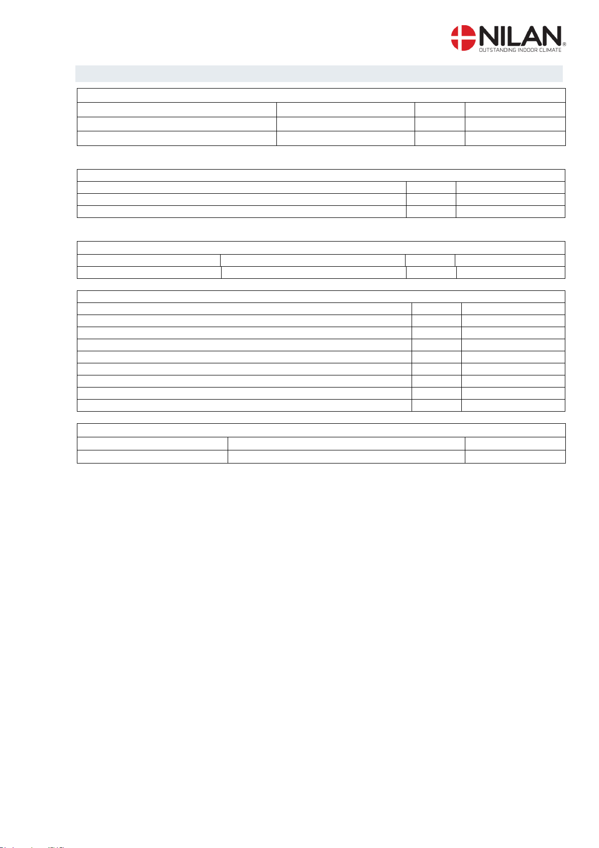
Filters
Type
System type
Qty
Nilan item no.
F7
Comfort 1200
1
3949
F5
Comfort 1200
1
3948
Heating surface for water incl. regulation
System
Qty
Nilan item no.
Comfort 1200 (right)
1
76792
Comfort 1200 (left)
1
76793
Electrical heating surface (for fitting in inlet duct)
System
Output
Qty
Nilan item no.
Comfort 1200
6kW, 400V, 3~
1
7644
Spare parts/accessories
Type
Qty
Nilan item no.
Hygrostat 1 3637
CTS 602, control PCB
1
239932
CTS 602, control panel, complete
1
2398
CTS 602, white control panel enclosure
1
2398HX
Filterguard excl. hose (3m item nr. 3049)
1
3635
Vibration absorber
1
7722401
Humidity sensor
1
23997
CO2-Sensor
1
7134B13
Heating cable for condensation outlet (frost protection)
System
Type
Nilan item no.
Comfort
Heating cable
2172
Accessories/spare parts
Nilan reserves the right to alter these instructions without prior notice Page 25 af 25
 Loading...