

Page 1

XT•350
&
XT•100
MOTORIZED TURNTABLES
MANUAL
The information in this manual is furnished for information use only, is subject to
change without notice, and not be construed as a commitment by Anything3D Corp.
Anything3D Corp assumes no responsibility or liability for any errors or inaccuracies
that may appear in this book.
© 20002001 Anything3D Corp. All right reserved.
Page 2

Page 3

CONTENS
1. Safety instructions .................................................. 2
2. Introduction............................................................ 6
3. Complete set of equipment .................................... 10
4. Description........................................................... 12
5. Installation ........................................................... 14
6. Operating controls ................................................ 16
7. Preparing for photography ..................................... 21
7.1 Connecting the Turntable .................................. 21
7.2. Starting the Turntable ...................................... 27
8. Operating modes .................................................. 29
9. Rotation speed adjustment mode ........................... 33
10. Manual mode...................................................... 37
11. Slave mode......................................................... 40
12. Optional auto mode............................................. 43
13. Frequently asked questions ................................. 46
14. Recommendations for use ................................... 48
15. Troubleshooting ................................................ 53
16. Maintenance ...................................................... 55
17. Specification ...................................................... 57
18. Product warranty................................................. 59
NIKON is a registered trademark of Nikon Corporation.
Anything3D and Anything3D logo are registered trademarks of
Anything3D Corporation.
Photo3D and Photo3D logo are registered trademarks of Anything3D
Corporation.
MS Windows is a registered trademark of Microsoft Corporation.
Page 4

1. SAFETY INSTRUCTIONS
4
1. Please, carefully read these instructions.
2. The turntable must be installed on a flat
horizontal surface, otherwise it won’t work
properly.
Figure 1.1
3. Use AC power source indicated in the
specification ONLY.
Figure 1.2
4. Turn on the equipment only via proper
5. Never use a damaged power cable.
6. When using an extension piece, make sure
1. SAFETY INSTRUCTIONS
ly earthed sockets.
that the total current value doesn’t exceed
the permissible one.
Page 5
7. The total current consumed by all devices
through the common outlet should not ex
ceed its rated current.
8. Always turn off the turntable if the power
cable or socket is damaged, if liquid has
got inside the turntable or if the turntable
works improperly.
Figure 1.3
9. After switching the turntable off DO NOT
switch it on again before 2 seconds have
elapsed.
5
10. Always switch off your turntable by using
the button on the power panel.
11. Never take the plug out of the socket
before the indicators on the control panel
go off.
12. Before cleaning the table disconnect it
from the power source.
13. Never use volatile flammable liquids
to clean the turntable.
1. SAFETY INSTRUCTIONS
Page 6
6
14. DO NOT perform maintenance and repair
of the turntable yourself. In case of any
trouble contact ANYTHING3D.
15. Make sure that during rotation the turnta
ble spinning surface doesn’t contact with
the external objects.
16. See to it that the load on the turntable is
as close to the center as possible or else it
might cause damage to the turntable.
(Fig. 1.4)
Figure 1.4
17. Never place the photographed objects on
1. SAFETY INSTRUCTIONS
CorrectIncorrect
the turntable while it is spinning.
to contents
Page 7

7
1. SAFETY INSTRUCTIONS
Page 8

2. INTRODUCTION
8
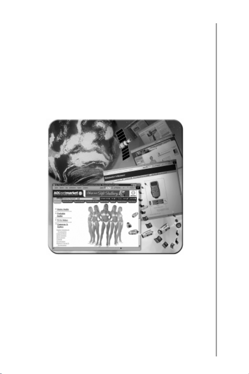
ANYTHING3D XT100 AND XT350 MOTOR
IZED TURNTABLES are intended for automa
tion of 3D photography process. With 3D
photography the objects you are taking pic
tures of can be seen on the computer screen
and you can get the complete visual informa
tion about all their features! Our turntable lets
you get the 3D images series of any object
you choose. This widely adaptable kind of 3D
images is in great demand. They could be
used in Internetshops, on the model agen
cies sites, at the advertising shows, presen
tations, etc.
XT350 model 39" in diameter is intended
for making the photos of people and large
objects. XT350 turntable is capable of
bearing the heavy objects with a weight of
up to 350 lb.
XT100 model is 20" in diameter and bears
the objects with a weight of up to 100 lb.
XT350 and XT100 turntables have the
same indication, controls and functional abil
ities. In addition to the common function
abilities ХТ350 turntable is equipped with a
frame number sound indication, as well as
with a pullout handle and wheels to move the
turntable around your photo studio.
The turntable enables a series consisting of
different quantities of images (32, 16 or 8
frames). You may take any number of frames
depending on your quality and technical re
quirements. A series of 32 frames produces a
2. INTRODUCTION
Page 9
9
2. INTRODUCTION
Page 10

10
highquality 3D photo with a bigger file size. A
series of 8 frames gives the smallest file size
and requires the least time to be loaded
through the Internet. A series of 16 frames is
a compromise between quality and file size.
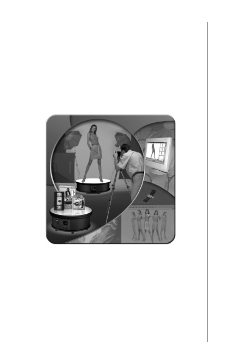
ANYTHING3D XT100 AND XT350 MOTOR
IZED TURNTABLES render 3D photography
as simple as 1,2,3! You may take pictures in
manual, semiautomatic or automatic
modes. The enhanced indicating system
gives you complete control over the process
of photography. Due to its adjustment sys
tem the turntable is well adaptable to the var
ious photo studio equipment and cameras.
The best results will be attained by means of
using a modern digital camera and a set of
the studio lighting equipment as in this case
you make the best of all the turntable appli
ances for automatic photography in order to
compile a 3D series.
The original Anything3D software included in
the complete set offers a wide variety of 3D
series processing options and their further
usage.
2. INTRODUCTION
Page 11
11
to contents
2. INTRODUCTION
Page 12
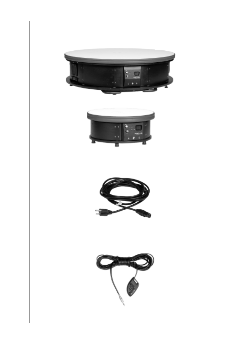
3. COMPLETE SET OF EQUIPMENT
12
1. Turntable (XT350 or XT100)
Figure 3.1
XT350
XT100
2. Power cable
Figure 3.2
3. COMPLETE SET OF EQUIPMENT
3. Remote control
Figure 3.3
Page 13
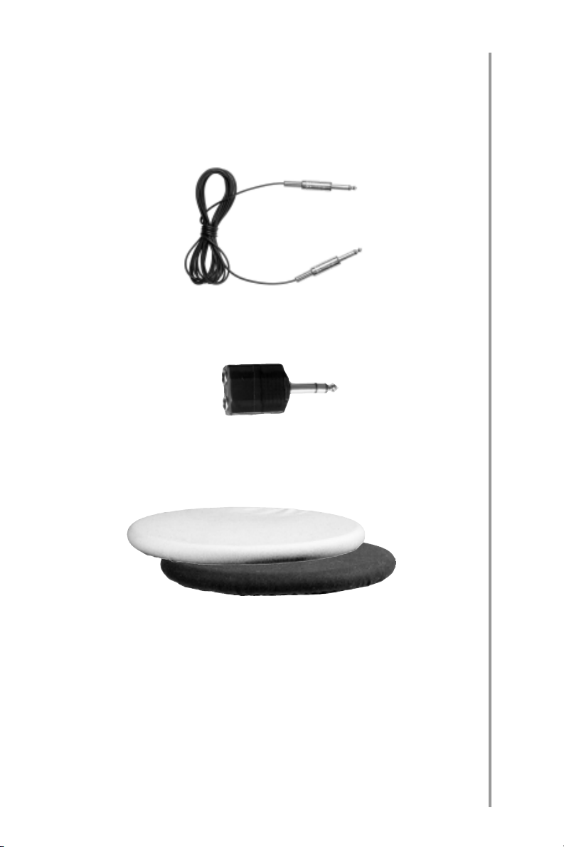
4. Turntable sync cable (intended for con
nection to the studio flash sync terminal
through the splitter)
Figure 3.4
5. Splitter (for connection to the studio flash
sync terminal)
Figure 3.5
6. 2 colored covers for the turntable rotating
surface
13
7. Manuals
8. Software CD
Figure 3.6
3. COMPLETE SET OF EQUIPMENT
to contents
Page 14
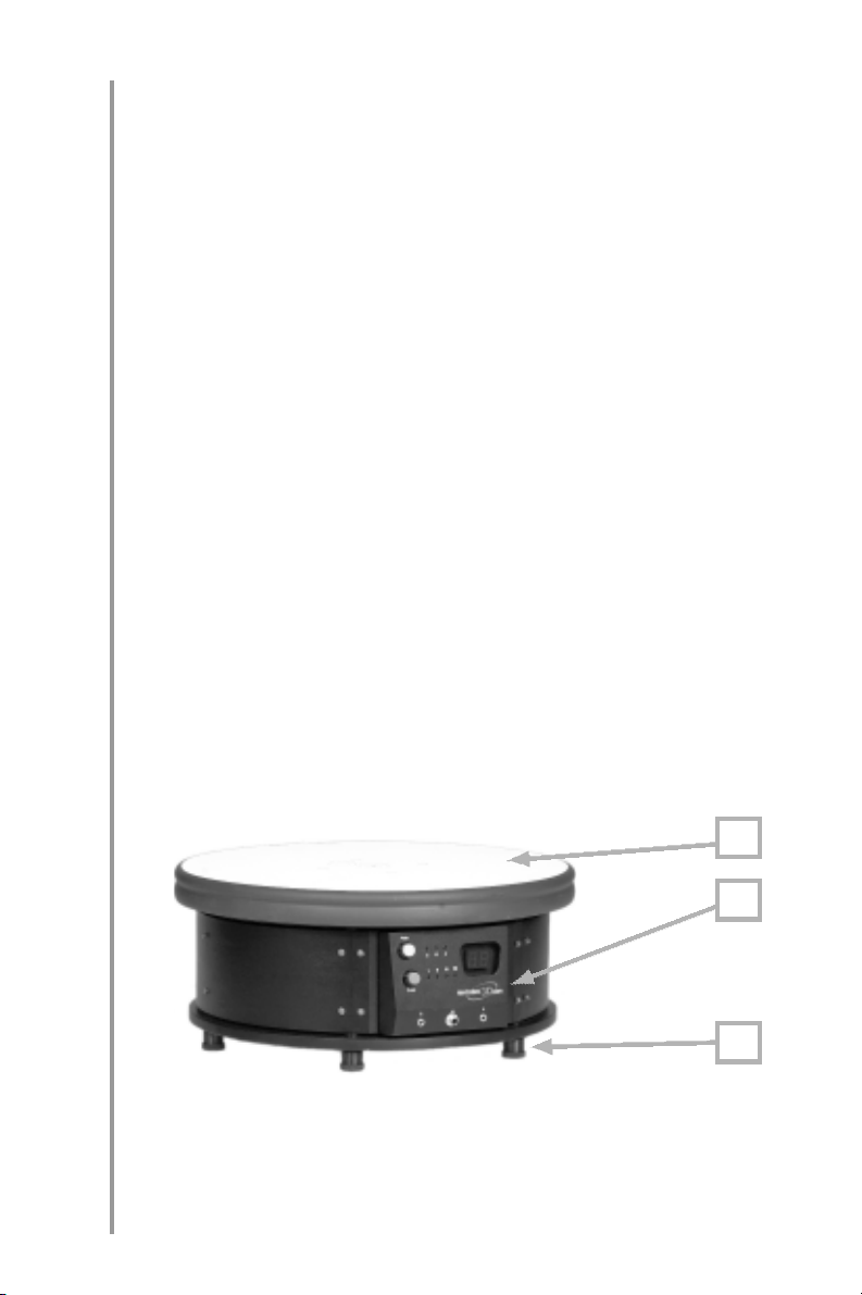
4. DESCRIPTION
14
The upper part of a turntable is a rotating disk
(Fig. 4.1a) on which the photographed object
is arranged. The disk can rotate in any direc
tion (both clockwise and counterclockwise).
Arranged on the turntable body are the con
trol panel (Fig. 4.1b, Fig.4.3c) and power
panel (Fig. 4.2a, Fig.4.4a).
Fixed on the turntable bottom are the adjust
able legs (Fig. 4.1c, Fig. 4.4c) designed for
adjusting the level of the turntable.
In addition the turntable model ХТ350 is
supplied with the sound control panel (Fig.
4.3a), pullout handle (Fig. 4.3b) and two
small wheels (Fig. 4.4b) used to move the
turntable around.
Figure 4.1
4. DESCRIPTION
a
b
c
Page 15

Figure 4.2
Figure 4.3
ba с
15
a
Figure 4.4
cba
4. DESCRIPTION
to contents
Page 16

5. INSTALLATION
16
Prior to photography locate the turntable on
a flat, horizontal and steady surface in your
photo studio or any other photography site at
your option in order to get the most efficient
position for photography. Avoid unstable or
vibrating places. Arrange the turntable so
that its control panel faces the camera.
For the XT350 turntable to be easily moved
about your photo studio it is supplied with a
handle and 2 small wheels. To move the turn
table pull out the handle located on its bot
tom (Fig. 5.1) against the stop; then begin
lifting the turntable till its whole weight rests
on the wheels (Fig. 5.2). After placing the
turntable at the required point let it acquire
horizontal position again and push the han
dle back as far as it will go.
5. INSTALLATION AND PREPARATION FOR PHOTOGRAPHY
Figure 5.1
Page 17
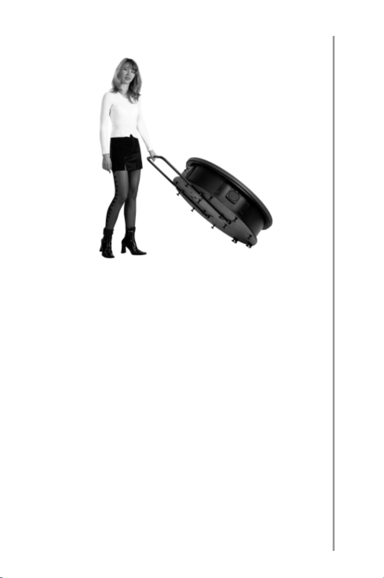
Figure 5.2
IMPORTANT: In order to protect the turnta
ble from damage DO NOT hold it by the rotat
ing disk when moving about!
For the device to operate properly its level
should be adjusted by screwing the bottom
legs in or out, each one in turn, until the rotat
ing surface of the turntable acquires horizon
tal position.
17
IMPORTANT: When installing a photo
graphed object on the turntable, please, re
member that the object should be fixed in the
center of the turntable and its weight should
not exceed the greatest permissible one.
DO NOT place heavy objects on the turntable
edge so that the mechanism does not get
damaged.
to contents
5. INSTALLATION AND PREPARATION FOR PHOTOGRAPHY
Page 18
6. OPERATING CONTROLS
18
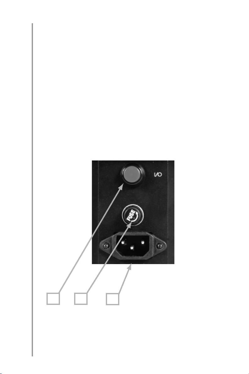
6.1. The power panel located on the turn
table body is intended for connecting the de
vice to the power source, as well as for
switching it on and off. Located on the power
panel are ON/OFF (I/O) button (Fig. 6.1a),
FUSE (Fig. 6.1b) and power cable socket
(Fig. 6.1c).
Figure 6.1
6. OPERATING CONTROLS
ba
c
Page 19
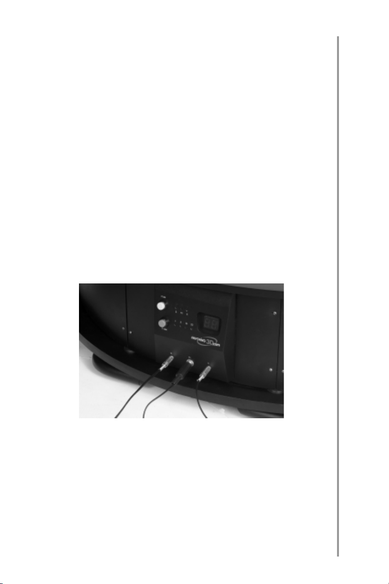
6.2. The control panel (Fig.6.2) located on
the turntable body is intended for operating
modes control and indication, and also for
remote control, studio flashes and camera
connection to the turntable by means of
special cables (included in the kit, optional).
The cables are plugged into the special
sockets (R, M, A) arranged on the control
panel bottom.
Figure 6.2.1
19
6. OPERATING CONTROLS
Page 20
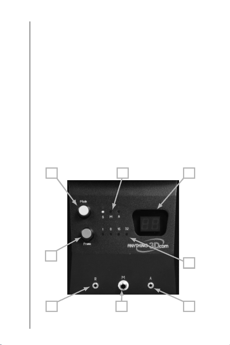
20
Located on the control panel are:
MODE button operating mode selection
(Fig. 6.2.2a);
FRAME button setting the number of the
frames (Fig. 6.2.2b);
Digital display indication of the frames
number in «M» and «A» modes and the rota
tion speed in «S» mode (Fig. 6.2.2c);
S, M, A operating modes indicators (Fig.
6.2.2d);
1, 8, 16, 32 indicators of the frames
number in a series (Fig. 6.2.2e);
R remote control socket (Fig. 6.2.2f);
Figure 6.2.2
6. OPERATING CONTROLS
a
cd
b
e
gf
h
Page 21

M the turntable sync cable socket (Fig.
6.2.2g);
A camera remote control cable socket for
the turntable operation in «Auto Mode» (Fig.
6.2.2h).
6.3. The sound control panel (XT350
only) located on the turntable body is intend
ed for the ON/OFF voice indication and vol
ume control. Arranged on the sound control
panel are the ON/OFF voice indication button
(Fig. 6.3a), sound ON/OFF indicator (Fig.
6.3b) and volume control handle (/+) (Fig.
6.3c). 2 speakers are also fixed on the turnta
ble body.
Figure 6.3
21
a b
c
6. OPERATING CONTROLS
Page 22

22
6.4. The remote control is intended for re
mote start of photography, selection of the
rotation direction, manual control of rotation
and adjustment of its speed.
The remote control is plugged into «R» sock
et on the control panel. Located on the re
mote control are (Fig.6.4):
a counterclockwise rotation button;
b clockwise rotation button;
c rotation instant stop and the pictures dig
ital counter reset button.
The buttons
(Fig.27a) and (Fig.27b)
control the turntable rotation direction. But
ton
(Fig.27c) resets the digital indication
on the Digital Display on the Control panel
and stops rotation.
a b c
Figure 6.4
6. OPERATING CONTROLS
to contents
Page 23

7. PREPARING FOR
PHOTOGRAPHY
7.1 CONNECTING THE TURNTABLE
IMPORTANT: Plug in/out the connectors R,
M and A only the power supply line is discon
nected from the turntable!
1. Plug the remote control into the connector
«R» on the control panel.
Figure 7.1.1
23
2. Plug the splitter into the studio flash sync
terminal .
Figure 7.1.2
7. PREPARING FOR PHOTOGRAPHY
Page 24

24
3.For «Manual» mode only: plug the turntable
sync cable into one of the splitter sockets
and the other end of the sync cable into
«M» socket on the control panel.
Figure 7.1.3a
7. PREPARING FOR PHOTOGRAPHY
Figure 7.1.3b
Page 25

4. Plug the studio flash sync cable which is
not included in the complete set of the
turntable equipment; but supplied togeth
er with the flash) into the second splitter
socket and its other end into the camera
sync terminal.
Figure 7.1.4a
25
Figure 7.1.4b
7. PREPARING FOR PHOTOGRAPHY
Page 26

26
5. The owners of the digital cameras with an
interface for Remote Control may take pic
tures in Auto Mode. In order to use Auto
Mode you will have to apply Optional
Adapter (Fig.7.1.5a) and Remote Control
Cable (Fig. 7.1.5b). Optional Adapter and
Remote Control Cable serve to connect a
camera to the turntable.
Figure 7.1.5a
7. PREPARING FOR PHOTOGRAPHY
Figure 7.1.5b
Page 27

6. Plug optional camera remote control
adapter into the camera special remote
terminal and connect the optional remote
control cable to the adapter pin jack. Plug
the other end of the remote control cable
into «A» connector on the turntable control
panel.
Figure 7.1.6a
27
Figure 7.1.6b
7. PREPARING FOR PHOTOGRAPHY
Page 28

28
7. Plug the power cable into the corre
sponding socket on the power panel and
then connect it to the AC supplyline.
Figure 7.1.8
7. PREPARING FOR PHOTOGRAPHY
Page 29

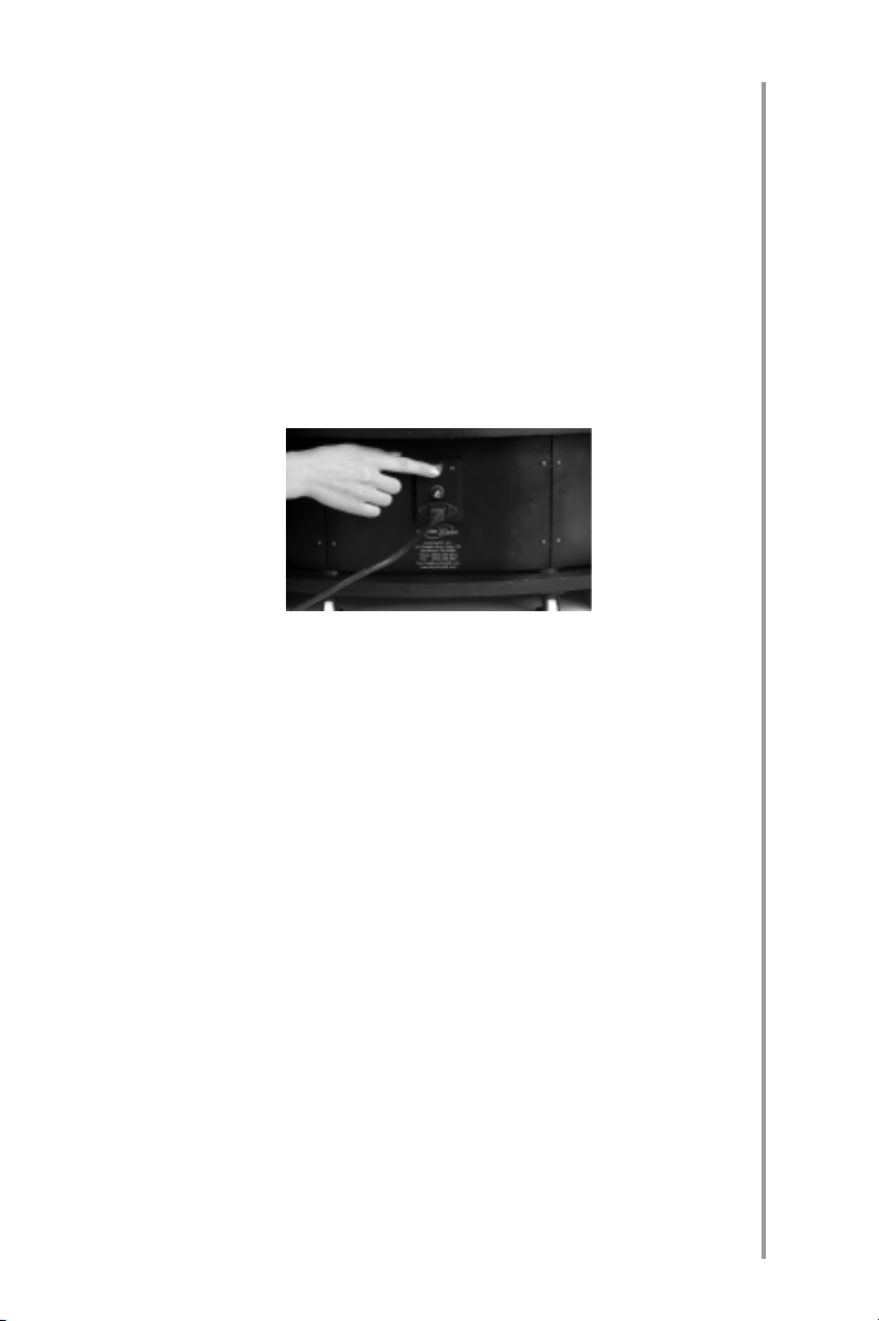
7.2. STARTING THE TURNTABLE
1. Depress the ON/OFF button (I/O) on the
power panel to switch on the turntable. The
indicators «M» and «32» on the control
panel will go on and digit «1» on the digital
display panel will also be displayed.
Figure 7.2.1
2. Depress the ON/OFF (I/O) button on the
sound control panel (XT350 only) to ini
tiate the sound indication; the LED locat
ed on same panel will go on. Then, using
the volume control knob set the desired
volume.
29
Figure 7.2.2
7. PREPARING FOR PHOTOGRAPHY
Page 30

30
3. To set the frames number in one series
(32, 16 or 8) for full turn press the «Frame»
button on the control panel. While rotation
the turntable will make the corresponding
number of stops for taking pictures. You
may also use the mode in which the turn
table makes a whole turn without any
stops by setting the light indicator «1» in
its ON position.
Figure 7.2.3
7. PREPARING FOR PHOTOGRAPHY
to contents
Page 31

8. OPERATING MODES
The turntable has different operating modes,
namely:
«S» mode (Rotation Speed Adjustment
Mode) where the turntable rotation speed is
set by remote control.
Figure 8.1
«М» mode has two versions – Manual
mode and Slave mode that differ in the
method of the turntable rotation control. In
Manual mode the turntable rotation is oper
ated by means of remote control. In Slave
mode the turntable obtains the control com
mands from the camera.
31
Figure 8.2
In Manual Mode you have the utmost control
over the 3D series photography process.
When using this mode you can change the
8. OPERATING MODES
Page 32

32
position of the object (e. g. in case you desire
to demonstrate the moving parts of the ob
ject or smoothly change the model’s atti
tude), return back and make the bad frame
once more.
Slave Mode enables the semiautomatic
photography. In order to get each frame of
the series you just need to press the camera
release.
In this mode the turntable rotates counter
clockwise.
«A» mode (Optional Auto mode). This is an
optional mode. The use of the cameras with
the remote control interface in this mode will
be possible after you acquire the Optional
Adapters and Remote Control Cable.
8. OPERATING MODES
Figure 8.3
In this mode the turntable makes only one
turn without a stop, and at the points of mak
ing a frame a command to operate the cam
era is given through the connector «А» on the
control panel. It is very easy to use Auto
mode and it saves time in the process of
shooting as you just need to press the button
Page 33

selecting the direction of rotation on the re
mote control and further on all the operations
in making the 3D series will be performed au
tomatically requiring no participation of the
photographer.
Prior to starting the turntable in any mode the
required quantity of frames in a series should
be set. To set the quantity of frames in a se
ries (32,16, 8 or 1) for one turn press the
«Frame» button on the control panel several
times. The indicators under the correspond
ing digits will go on.
33
Figure 8.4
8. OPERATING MODES
Page 34

34
Additional information:
1. Voice message always duplicates the indi
cation (if the sound indication is ON);
2. Pressing the «Mode» button always caus
es the turntable to stop and the digital display
to reset;
3. The quantity of the frames may be set only
when the turntable has stopped; at the same
time the indication on the digital display will
also reset;
4. The mode with the number of frames set to
«1» is intended for viewing the object, there
fore, indication on the digital display is not
available in this mode.
8. OPERATING MODES
to contents
Page 35

9. ROTATION SPEED
ADJUSTMENT MODE
The rotation speed of the turntable should be
shosen prior to photography. It will depend
on the photo equipment abilities: the time re
quired for the flashbulbs charging between
the pulses and also the time required for en
tering the information into the computer or
recording it on the flashcard in the digital
cameras. To set the required rotation speed,
proceed as follows:
1. Turn on 4 the turntable by pressing red
ON/OFF (I/O) button on the power panel.
35
Figure 9.1
3. Choose mode «S» by pressing the «Mode»
button.
Figure 9.2
9. ROTATION SPEED ADJUSTMENT MODE
Page 36

36
2. Choose the required quantity of the frames
(8, 16, 32) by pressing «Frame» button.
Figure 9.3
4. Press a button determining the rotation di
9. ROTATION SPEED ADJUSTMENT MODE
rection on the remote control (
crease the speed and
will decrease it).
will in
The turntable will start to rotate. Press the
rotation control button on the remote con
trol a several times in succession in order
to set the required rotation speed.
Figure 9.4
Page 37

5. In «S» mode the digits indicate the
number of seconds required for the turn
table to move from one frame to another;
e. g. «8» means that it takes 8 seconds for
the turntable to move from one frame to
the next one.
Figure 9.5
6. In order to switch over from the “S” mode
to any other operation mode press the
“Mode” button on the control panel. The
“S” mode operation completed the turnta
ble rotation stops. The determined speed
value is used for further operation.
37
Figure 9.6
9. ROTATION SPEED ADJUSTMENT MODE
Page 38

38
The minimal rotation speed is set when the
turntable is switched on for the first time.
The turntable will maintain the set speed of
rotation after it is turned off.
IMPORTANT: In «S» mode the continuous
rotation of the turntable should not exceed
10 minutes.
9. ROTATION SPEED ADJUSTMENT MODE
to contents
Page 39

10. MANUAL MODE
In this mode to create a 3D series the turnta
ble with an object on it should rotate after
each shot by means of the remote control.
The turntable may rotate both clockwise and
counterclockwise at your option. The direc
tion of rotation is prescribed by pressing the
corresponding button on the remote control.
IMPORTANT: Operation in Manual Mode re
quires the turntable connection to Remote
Control only. The Turntable Sync Cable
should be disconnected from the jack “M” on
the control panel.
To shoot in Manual Mode proceed as follows:
1. Switch on the turntable by pressing the red
ON/OFF (I/O) button on the power panel.
39
Figure 10.1
2. Choose «М» mode by pressing the «Mode»
button.
Figure 10.2
10. MANUAL MODE
Page 40

40
3. Choose the required quantity of frames
(8, 16, 32) by pressing the «Frame»
button.
Figure 10.3
4. Take the first picture with the camera.
10. MANUAL MODE
Figure 10.4
5. Press one of the buttons on the remote
control to set the direction of rotation. After
Figure 10.5
Page 41

that the rotating surface of the turntable
will move to the next frame. Indication of
the digital display located on the control
panel will increase by one.
6.If required the bad shot may be taken
again. With this aim press the other button
control rotation on the remote control. The
turntable will go back to the previous shot
position. Take the picture. Then press the
first rotation controlling button to resume
the movement of the turntable in the previ
ously set direction.
Figure 10.6
41
6. Take the next picture after the rotation has
ceased.
7. Depress the button on the remote control
once again and take the pictures one by
one in each point of photography until ro
tation is completed. Indication of the digital
display on the control panel should coin
cide with the set number of frames in the
series. The moment of photography of
each frame is accompanied with sound in
dication (XT350 only).
to contents
10. MANUAL MODE
Page 42

11. SLAVE MODE
42
Slave Mode is a semiautomatic mode. Op
erated in this mode the turntable rotates till
the point of making the next frame after
pressing the camera shutter release. The
mode is more convenient as there is no need
to use remote control for the turntable rota
tion, i. e. first the picture is made and then the
turntable rotating surface spins automatical
ly till the next frame and so on. The operation
order in this mode is as follows:
1. Connect the turntableto the sync termi
nals of the camera (Fig. 11.1) and flash
by means of the splitter and cables (Fig.
11.2) as it is pointed out in item 6.2
above via «М» connector.
11. SLAVE MODE
Figure 11.1
Figure 11.2
Page 43

2.Choose «M» mode by means of the
«Mode» button .
Figure 11.3
3. Set the quantity of frames points (8 16
32) by means of «Frame» mode.
Figure 11.4
43
4. Take a picture by pressing the camera re
lease. After that the turntable will automat
ically get to the next frame.
Figure 11.5
11. SLAVE MODE
Page 44

44
5. Take the next picture when the table has
stopped.
6. Take pictures in each point of photography
till the turn is completed.
The digital display on the control panel shows
the frame number. The moment of photogra
phy of each frame is accompanied with
sound indication (XT350 only).
In this mode only counterclockwise rotation
is supported.
11. SLAVE MODE
to contents
Page 45

12. OPTIONAL AUTO MODE
In Auto Mode during the process of photog
raphy the turntable makes one complete turn
without any stops. It makes the time of pho
tography shorter and gives the opportunity to
improve the 3D series quality when taking
pictures of the photo models.
The Auto Mode enables a whole series of pic
tures by way of pressing just one button on
the remote control. The frames are made au
tomatically as the turntable controller sends
the control signal to the camera at each next
frame point. This mode is applicable for the
digital cameras with the remote control inter
face. The adapter and camera remote control
cables are not included in the complete set of
equipment.
1. Insert the optional camera remote cable
into socket «A» on the control panel by us
ing the remote control cable and adapter
connector.
45
Figure 12.1
12. OPTIONAL AUTO MODE
Page 46

46
2. Set «A» mode by pressing the «Mode»
button.
Figure 12.2
3. Set the required quantity of frames (8, 16,
32) by pressing the «Frame» button.
Figure 12.3
12. OPTIONAL AUTO MODE
4. Now, by pressing one of the buttons on the
remote control the turntable will be caused
to start its rotation in the prescribed direc
tion, and the camera will take pictures at
Figure 12.4
Page 47

each stop of the turntable in any point of
photography.
A complete series of pictures will be obtained
in this manner.
The digital display on the control panel shows
the frame number. The moment of photogra
phy of each frame is accompanied with
sound indication (XT350 only).
The set parameters will be retained after the
turntable is switched off.
NOTE: In Auto Mode the turntable synch ca
ble connected to «M» jack may be removed
as it is not used. However, the connected
synch cable won’t affect the turntable opera
tion in Auto Mode.
47
to contents
12. OPTIONAL AUTO MODE
Page 48

48
13. FREQUENTLY ASKED
QUESTIONS
Question 1: What is to be done if the camera
does not possess a synch contact for the
flash bulb synch cable ?
Answer: There is a number of solutions to
this problem :
1. If the camera lacks a synch contact for the
flash bulb synch cable and if the synch
contact is nonstandard or arranged in the
place of the flash bulb attachment on the
camera it is recommended to purchase an
adapter with a standard synch contact ;
2. If the studio pulse light and a stationary
flash bulb on the camera are used the stu
dio flash bulbs should be equipped with
light synchronizers.
3. Use constant illumination.
Question 2: What is to be done if the camera
does not possess a connector for the camera
remote control adapter?
13. FREQUENTLY ASKED QUESTIONS
Answer: All the turntable operation modes,
except Auto one, may be used. The camera
remote control cable is not used in this case
and there is no need to connect it to socket
«A» on the control panel.
Question 3: If the photo studio is supplied
with constant illumination, in what way
should the photography be made?
Answer: When applying the constant illumi
nation you may use all the turntable opera
tion modes and there is no need to use the
Page 49

synch cable intended for the turntable con
nection to synch pin jack of the camera and
that intended for connecting the camera to
the flash.
49
to contents
13. FREQUENTLY ASKED QUESTIONS
Page 50

50
14. RECOMMENDATIONS
FOR USE
1. Always place the turntable on a firm sur
face which will not get dented and use
special devices if the turntable requires
levelling.
Figure 14.1
2. Arrange the equipment connecting cables
so that nobody touches them when moving
around the studio. The cables may be fiy p
of an adhesive tape and it will help to avoid
damaging both people and equipment.
14. RECOMMENDATIONS FOR USE
3. Adjust the turntable rotation speed in con
junction with that of the camera (it takes
some time with digital cameras to store the
information).
4. When taking photographs of the people in
all modes except Auto one it is recom
mended to use a low speed of the turntable
rotation for smooth movement (and to help
the photographed person to maintain his
attitude without much effort). In Auto Mode
use the greatest speed of rotation allowed
Page 51

by your photographic equipment for a se
ries of images.
5. Use mainly auto mode («A» mode) when
you take photos of the static objects to
save your time.
6. Slave or Manual Modes («M» mode) are
more suitable when you take the photos of
people; make sure that the model keeps
her/his eyes open to avoid having the
frames where the eyes are closed.
7. Application of the turntable enables ani
mated 3D series. As a result it is possible to
get very chic 3D series of the photo models
making some movements during rotation
or changing their attitude, and also of
some transforming objects (the movable
parts of which may be drawn in/out or ro
tated) and give more complete information
about the object.
8. Say, you want to make a 32frame 3D se
ries where being rotated the photogra
pher’s model gently raises her hand, titi
vates her hair and then puts her hand down
again. It is recommended to train this
movement on the rotating turntable before
taking pictures by the camera. The model
must split her movement into 32 phases so
that after making a full turn she may ac
quire the initial attitude. The voice indica
tion of the frames will help to do so. For ex
ample, the movement of the hand starts
from the 3rd frame, the hand reaches the
51
14. RECOMMENDATIONS FOR USE
Page 52

52
highest point by the 13th frame and the
model fixes her hair. Starting from the 18th
frame the hand moves down and acquires
the initial position by the 30th frame.
9. When working in the Manual or SemiAuto
matic Modes you can make the animated
3D series of the objects. For instance, you
may show how during rotation of the scan
ner its lid is being opened and closed.
When the turntable stops after a frame the
position of its lid must be changed a little so
that, say, from frame 4 to frame 13 the lid
will be evenly opened, from frame 14 to
frame 18 it will be fixed in the open position
and closed from frame 19 to frame 29.
While doing this it is very convenient to get
the information about the turntable posi
Figure 14.2
14. RECOMMENDATIONS FOR USE
Page 53

tion (about the number of the frame) by
means of the voice indication. The interja
cent positions of the lid may be fixed with
the help of anything you have at hand, ten
sion members, for example. They may be
removed from the image during the photo
graphs processing.
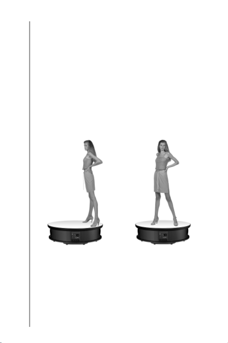
10. Start photography from the model’s back
to make sure that the 1st and 32nd frames
of the series get stitched smoothly without
displacement of the model as in this case
the insignificant shift of the model from the
32nd frame to the 1st one is practically un
noticeable. (Fig.14.2)
Figure 14.2
53
14. RECOMMENDATIONS FOR USE
Page 54

54
11. Use white background as much as you
can and adjust the object illumination
(steadily N) so that the background and
the turntable surface blend. It will simplify
further processing of the series by the im
age editor.
12. If the ready images are to be arranged
against a light background use the acces
sory light cover for the table surface (in
cluded in the kit) and the light background
to avoid a dark outline around the object.
Accordingly, it is preferable to use the ac
cessory dark cover (also included in the
kit) and a dark background (the back
ground cover is not included in the com
plete set of the turntable equipment) to
take the photos of the objects arranged on
a dark background.
13. The changeable covers must be washed
as they get dirty. They may be washed both
by hands and washing machine at a tem
perature below 140°F.
14. RECOMMENDATIONS FOR USE
14. Apply the camera auto focus only for pre
liminary adjustment for sharpness and dis
able it in the process of taking the photos.
to contents
Page 55

15. TROUBLE(SHOOTING
Malfunction Possible Cause Remedy
55
Turntable
won't switch
on by pressing
ON/OFF
button (I/O)
Turntable gets
energized but
indication on
digital panel is
invalid
Frame
numbers are
changed on
digital
indication
panel but the
turntable
surface won't
move
1. Turntable isn't
connected to AC
power supply-line.
2. Power cable is not
tightly plugged into its
socket on power
panel.
3. Burnt fuse on
power panel.
You plugged cables in
"R", "M" and "A"
sockets prior to
disconnecting the
turntable from AC
power supply-line.
1. You have violated
the instruction and
photographed the
objects or people
whose weight was
greater than maximal
permissible one.
Rotation gear is
damaged.
2. You often
photograph objects
located far from
turntable centre.
Rotation gear is
damaged.
1. Connect the
turntable to AC
power supplyline.
2. Disconnect
the cable from
switching
connector and
plug it in again.
3. Replace fuse
on power panel.
Switch the
turntable off,
connect cables
properly
following the
instruction and
then switch the
turntable on.
Contact
Anything3D.
15. TROUBLE(SHOOTING
Page 56

56
Malfunction Possible Cause Remedy
Studio flash
won't work in
slave or auto
mode.
1. Unreliable contact
in camera sync
terminal or studio
flash.
2. Damaged cable
connecting studio
flash and "M" socket.
3. Unreliable contact
with control panel
sockets or in splitter
connected to studio
flash.
1. Make sure
that camera
sync terminal is
operable and its
contact with
flash is reliable.
2. Replace
cable.
3. Test cable and
"M" connector
contact on
control panel for
reliability; make
sure that
required splitter
contact is
connected to
sync terminal.
15. TROUBLE(SHOOTING
to contents
Page 57

16. MAINTENANCE
1. In order to replace the fuse proceed as fol
lows :
a. Disconnect the power supply wire from
the AC power supplyline;
Figure 16.1
b. Screw out the cap with the fuse by turn
ing it counterclockwise ;
57
Figure 16.2
c. Replace the fuse ;
d. Screw in the cap with the new fuse ;
e. Connect the power supply wire to the
supply line.
2. Clean the turntable from dust on a regular
scale.
16. MAINTENANCE
Page 58

58
3. Flannel the turntable rotating surface as it
gets soiled.
4. Do not use solvents, petrol etc. for clean
ing the turntable.
5. Do not allow liquids to get inside the turn
table.
16. MAINTENANCE
to contents
Page 59

17. SPECIFICATION
1. Rotation surface diameter:
• 40 inches (XT350);
• 20 inches (XT100).
2. Rotation speed:
• min 1 turn / 168 sec;
• max 1 turn / 72 sec.
3. Rotation speed adjustment:
• smooth.
4. Rotation direction:
• clockwise;
• counterclockwise.
5. Information about rotation speed:
• visual (digital indication).
6. Information about photography point
number:
• visual (digital indication);
• voice ( XT350 only).
59
7. Frames number / 1 turn:
• 8;
• 16;
• 32.
8. Rotation characteristics :
• continuous rotation control signal is
sent to the camera in each point of pho
tography, and the picture is taken0 with
out stopping the turntable;
17. SPECIFICATION
Page 60

60
• discrete rotation turntable is stopped at
each photography point and then is
started again.
9. Maximal permissible weight of the object
placed on the turntable:
• 350 pounds (XT350);
• 100 pounds (XT100).
10. Overall dimensions:
• 40x40x11 inches (XT350);
• 20x20x8 inches (XT100).
11. Power supply AC 110 V ± 10%, 60 Hz ±3
Hz.
12. Power consumption 150 W.
13. Ambient atmosphere conditions:
• operating temperature 32°F to 95°F;
• operating humidity 10% to 80%;
• storage temperature 4°F to 113°F;
• storage humidity 5% to 95%.
17. SPECIFICATION
to contents
Page 61

18. PRODUCT WARRANTY
This product is guaranteed to be free from
manufacturing defects in material and work
manship under normal use for a period of
1(one) year from the date of purchase. If a
defect that is covered by the foregoing war
ranty occurs during the applicable period
stated above, Anything3D Corp., at its op
tion, will either repair or replace the product,
and such action on the part of Anything3D
Corp. shall be the full extent of Anything3D
Corp. liability, and the Customer’s sole and
exclusive remedy. This warranty does not
cover a product (a) used in other than its nor
mal and customary manner; (b) subject to
misuse; (c) subject to alterations, modifica
tions or repairs by the Customer of by any
party other than Anything3D Corp. without
prior written consent of Anything3D Corp.;
(d) special order or «closeout» merchandise
or merchandise sold «asis» by either
Anything3D Corp. or the Anything3D Corp.
dealer; or (e) merchandise that has been dis
continued by the Anything3D and either parts
or replacement units are not available due to
reasons beyond the control of Anything3D
Corp.
61
Anything3D Corp. shall not be responsible
for any defects or damage that in Anything3D
Corp.’s opinion is a result of mishandling,
abuse, misuse, improper storage or improp
er operation, including use in conjunction
with equipment which is electrically or me
chanically incompatible with or of inferior
18. PRODUCT WARRANTY
Page 62

62
quality to the product, as well as failure to
maintain the environmental conditions speci
fied by the Anything3D. This warranty is ex
tended only to the original purchaser. Any
breach of this warranty shall be waived un
less the customer notifies Anything3D Corp.
at the address noted below within the appli
cable warranty period.
THE CUSTOMER UNDERSTANDS AND
AGREES THAT EXCEPT FOR THE FOREGO
ING WARRANTY, NO OTHER WARRANTIES,
WRITTEN OR ORAL, STATUTORY, EX
PRESSED OR IMPLIED, INCLUDING ANY IM
PLIED WARRANTY OF MERCHANTABILITY
OR FITNESS FOR A PARTICULAR PURPOSE,
SHALL APPLY TO THE PRODUCT. ALL SUCH
IMPLIED WARRANTIES ARE HEREBY EX
PRESSLY DISCLAIMED.
LIMITATION OF LIABILITY
18. PRODUCT WARRANTY
Anything3D Corp. will not be liable for any
claims, actions, proceedings, costs, expens
es, damages or liabilities arising out of the
use of this product. Operation and use of the
product are the sole responsibility of the Cus
tomer. Anything3D Corp.’s sole undertaking
is limited to providing the products and serv
ices outlined herein in accordance with the
terms and conditions of this Agreement. The
provision of products sold and services per
formed by Anything3D Corp. to the Customer
shall not be interpreted, construed, or re
garded, either expressly or implied, as being
Page 63

for the benefit of or creating any obligation
forward any third party of legal entity outside
Anything3D Corp. and the Customer;
Anything3D Corp.’s obligations under this
Agreement extend solely to the Customer;
ANYTHING3D CORP.’S LIABILITY HEREUN
DER FOR DAMAGES, REGARDLESS OF THE
FORM OR ACTION, SHALL NOT EXCEED
THE FEES OR OTHER CHARGES PAID TO
ANYTHING3D CORP. BY THE CUSTOMER
OR CUSTOMER’S DEALER. ANYTHING3D
CORP. SHALL NOT, IN ANY EVENT, BE LIABLE
FOR SPECIAL, INDIRECT, INCIDENTAL, OR
CONSEQUENTIAL DAMAGES INCLUDING,
BUT NOT LIMITED TO, LOST INCOME, LOST
REVENUE OR LOST PROFIT, WHETHER
SUCH DAMAGES WERE FORESEEABLE OR
NOT AT THE TIME OF PURCHASE, AND
WHETHER OR NOT SUCH DAMAGES ARISE
OUT OF A BREACH OF WARRANTY, A
BREACH OF AGREEMENT, NEGLIGENCE,
STRICT LIABILITY OR ANY OTHER THEORY
OF LIABILITY.
63
PRODUCT WARRANTY REGISTRATION
In order to validate the warranty on your
product, Anything3D Corp. must receive a
completed Product Warranty Registration
Card for each unit. Please, complete the
form below and immediately mail it to our
Service Center: Anything3D Corporation,
901 Sneath Ln. Suite 105 San Bruno CA
94066. Products qualifying for warranty re
18. PRODUCT WARRANTY
Page 64

64
pair will be either repaired or replaced within I
O business days of receipt of merchandise
unless the customer is notified otherwise.
OBTAINING WARRANTY SERVICE
To obtain warranty service on your unit, take
or send the product, postage paid, with a
copy of your sales receipt to our service cent
er, Anything3D Corporation at the address
noted above. All merchandise must be fully
insured with the correct postage: Anything3D
Corporation will not be responsible for im
proper postage, or missing or damaged mer
chandise during shipment.
18. PRODUCT WARRANTY
to contents
 Loading...