

Page 1
Wireless Transmitter
User's Manual
En
Page 2

Trademark Information
Macintosh and Mac OS are trademarks of Apple Computer, Inc. Microsoft,
Windows, and Windows Vista are registered trademarks of Microsoft
Corporation. CompactFlash is a trademark of SanDisk Corporation.
other trade names mentioned in this manual or the other documentation
provided with this Nikon product are trademarks or registered trademarks
of their respective holders.
All
Apple Public Source License
This product includes Apple mDNS source code that is subject to the
terms of the Apple Public Source License located at URL
http://developer.apple.com/darwin/.
Portions copyright © 1999-2003 Apple Computer, Inc. All Rights Reserved.
This file contains Original Code and/or Modifications of Original Code as
defined in and that are subject to the Apple Public Source License Version
2.0 (the ‘License’). You may not use this file except in compliance with the
License. Please obtain a copy of the License at
http://www.opensource.apple.com/apsl/ and read it before using this
file.
The Original Code and all software distributed under the License are
distributed on an ‘AS IS’ basis, WITHOUT WARRANTY OF ANY KIND, EITHER
EXPRESS OR IMPLIED, AND APPLE HEREBY DISCLAIMS ALL SUCH
WARRANTIES, INCLUDING WITHOUT LIMITATION, ANY WARRANTIES OF
MERCHANTABILITY, FITNESS FOR A PARTICULAR PURPOSE, QUIET
ENJOYMENT OR NON-INFRINGEMENT. Please see the License for the
specific language governing rights and limitations under the License.
Page 3
For Your Safety
To prevent damage to your Nikon product or injury to yourself or to
others, read the following safety precautions in their entirety before using
this equipment. Keep these safety instructions where all those who use
the product will read them.
The consequences that could result from failure to observe the
precautions listed in this section are indicated by the following symbol:
This icon marks warnings, information that should be read before
using this Nikon product to prevent possible injury.
❏ WARNINGS
Do not disassemble
Failure to observe this precaution could result in fire, electric shock, or other
injury. Should the product break open as the result of a fall or other accident,
disconnect the camera power source and take the product to a Nikonauthorized service representative for inspection.
Cut power immediately in the event of malfunction
Should you notice smoke or an unusual smell coming from the equipment,
immediately unplug the AC adapter and remove the battery, taking care to
avoid burns. Continued operation could result in injury. After removing the
battery, take the equipment to a Nikon-authorized service representative for
inspection.
Do not use in the presence of flammable gas
Failure to observe this precaution could result in explosion or fire.
Keep dry
Do not immerse in or expose to water or rain. Failure to observe this
precaution could result in fire or electric shock.
Do not handle with wet hands
Failure to observe this precaution could result in electric shock.
Keep out of reach of children
Failure to observe this precaution could result in injury.
For Your Safety
i
Page 4

Observe proper precautions when handling batte ries
Batteries may leak or explode if improperly handled. Observe the following
precautions when handling batteries for use in this product:
• Be sure the product is off before replacing the battery. If you are using an AC
For Your Safety
adapter, be sure it is unplugged.
• Use only batteries approved for use in this equipment.
• Do not attempt to insert the battery upside down or backwards.
• Do not short or disassemble the battery.
• Do not expose the battery to flame or to excessive heat.
• Do not immerse in or expose to water.
• Replace the terminal cover when transporting the battery. Do not transport
or store with metal objects such as necklaces or hairpins.
• Batteries are prone to leakage when fully discharged. To avoid damage to
the product, be sure to remove the battery when no charge remains.
• When the battery is not in use, attach the terminal cover and store in a cool
place.
• Immediately after use, or when the product is used on battery power for an
extended period, the battery may become hot. Before removing the battery,
turn the camera off and allow the battery to cool.
• Discontinue use immediately should you notice any changes in the battery,
such as discoloration or deformation.
Do not expose to high temperatures
Do not leave the device in a closed vehicle under the sun or in other areas
subject to extremely high temperatures. Failure to observe this precaution
could result in fire or in damage to the casing or internal parts.
Observe caution when using the antenna
When using the antenna, be careful not to put the tip of the antenna in your
eye accidentally. Failure to observe this precaution could result in blindness or
other visual impairment.
CD-ROMs
The CD-ROMs on which the software and manuals are distributed should not
be played back on audio CD equipment. Playing CD-ROMs on an audio CD
player could cause hearing loss or damage the equipment.
Follow the instructions of hospital and airline personnel
This device emits radio frequency radiation that could interfere with medical
or navigational equipment. Do not use this device in a hospital or on board an
airplane without first obtaining the permission of hospital or airline staff.
ii
Page 5

Notices
• No part of the manuals included with this product may be reproduced,
transmitted, transcribed, stored in a retrieval system, or translated into
any language in any form, by any means, without Nikon’s prior written
permission.
• Nikon reserves the right to change the specifications of the hardware
and software described in these manuals at any time and without prior
notice.
• Nikon will not be held liable for any damages resulting from the use of
this product.
• While every effort has been made to ensure that the information in
these manuals is accurate and complete, we would appreciate it were
you to bring any errors or omissions to the attention of the Nikon
representative in your area (address provided separately).
This product, which contains encryption software developed in the
United States, is controlled by the United States Export Administration
Regulations and may not be exported or re-exported to any country to
which the United States embargoes goods. As of August 2007 the
following countries were subject to embargo: Cuba, Iran, North Korea,
Sudan, and Syria.
Notices
iii
Page 6

Notice for Customers in the U.S.A.
❏ U.S.A. Federal Communications Commission (FCC)
Declaration of Conformity
Notices
This device complies with Part 15 of FCC rules and RSS-Gen of IC rules.
Operation is subject to the following two conditions: (1) this device may not
cause harmful interference, and (2) this device must accept any interference
received, including interference that may cause undesired operation of this
device.
Products that contain a radio
transmitter are labeled with FCC ID
and may also carry the FCC logo.
FCC Radio Frequency Interference S tatement
This equipment has been tested and found to comply with the limits for a
Class B digital device, pursuant to Part 15 of the FCC rules. These limits are
designed to provide reasonable protection against harmful interference in a
residential installation. This equipment generates, uses, and can radiate radio
frequency energy and, if not installed and used in accordance with the
instructions, may cause harmful interference to radio communications.
However, there is no guarantee that interference will not occur in a particular
installation. If this equipment does cause harmful interference to radio or
television reception, which can be determined by turning the equipment off
and on, the user is encouraged to try to correct the interference by one or
more of the following measures:
• Reorient or relocate the receiving antenna.
• Increase the separation between the equipment and receiver.
• Connect the equipment into an outlet on a circuit different from that to
which the receiver is connected.
• Consult the dealer or an experienced radio/television technician for help.
CAUTIONS
Modifications
The FCC requires the user to be notified that any changes or modifications
made to this device that are not expressly approved by Nikon Corporation
may void the user’s authority to operate the equipment.
Interface Cables
Use the interface cables sold or provided by Nikon for your equipment. Using
other interface cables may exceed the limits of Class B Part 15 of the FCC rules.
iv
Page 7

Indoor operations
In accordance with 47 CFR Part 15.407 (e) U-NII, devices operating in 5.15–
5.25 GHz frequency bands are restricted to indoor operations only.
Co-loc ation
This transmitter must not be co-located or operated in conjunction with any
other antenna or transmitter.
FCC/IC RF Exposure Statement
The available scientific evidence does not show that any health problems are
associated with using low power wireless devices. There is no proof, however,
that these low power wireless devices are absolutely safe. Low power Wireless
devices emit low levels of radio frequency energy (RF) in the microwave range
while being used. Whereas high levels of RF can produce health effects (by
heating tissue), exposure to low-level RF that does not produce heating effects
causes no known adverse health effects. Many studies of low-level RF
exposures have not found any biological effects. Some studies have suggested
that some biological effects might occur, but such findings have not been
confirmed by additional research. This Wireless Transmitter (WT-4A), which is
equipped with an SX-10WAG (FCC ID: N6C-SX10WAG / IC: 4908B-SX10WAG)
Wireless LAN Module, has been tested and found to comply with FCC radiation
exposure limits set forth for uncontrolled equipment and meets the FCC radio
frequency (RF) Exposure Guidelines in Supplement C to OET65 and RSS-102 of
the IC radio frequency (RF) Exposure rules. Please refer to the SAR test report
that was uploaded to FCC website.
This WT-4A has been tested and meets the FCC RF exposure guidelines when
used with the Nikon Corporation accessories supplied or designated for this
product. Use of other accessories may not ensure compliance with FCC RF
exposure guidelines.
Notice for Customers in the State of California, U.S.A.
WARNING : Handling the cord on this product will expose you to lead, a chemical
known to the State of California to cause birth defects or other reproductive
harm. Wash hands after handling.
Nikon Inc.,
1300 Walt Whitman Road, Melville, New York
11747-3064, U.S.A. Tel.: 631-547-4200
Notices
v
Page 8

Notices for Customers in Canada
CAUTION : This class B digital apparatus complies with Canadian ICES-003.
ATTENTION : Cet appareil numerique de la classe B est conforme a la norme
Notices
NMB-003 du Canada.
❏ IC RSS-GEN Exposure of Humans to RF Fields
This device complies with Part 15 of FCC Rules and RSS-Gen of IC Rules.
Operation is subject to the following two conditions: (1) this device may not
cause harmful interference, and (2) this device must accept any interference
received, including interference that may cause undesired operation of this
device.
This device has been designed to operate with an antenna having a maximum
gain of 2.1 dBi. Industry Canada regulations strictly prohibit antennas with
higher gain. The required antenna impedance is 50 ohms.
To reduce potential radio interference to other users, the antenna type and its
gain should be so chosen that the equivalent isotropically radiated power
(EIRP) is not more than that required for successful communication.
Co-loc ation
This transmitter must not be co-located or operated in conjunction with any
other antenna or transmitter.
FCC/IC RF Exposure Statement
The available scientific evidence does not show that any health problems are
associated with using low power wireless devices. There is no proof, however,
that these low power wireless devices are absolutely safe. Low power Wireless
devices emit low levels of radio frequency energy (RF) in the microwave range
while being used. Whereas high levels of RF can produce health effects (by
heating tissue), exposure to low-level RF that does not produce heating effects
causes no known adverse health effects. Many studies of low-level RF
exposures have not found any biological effects. Some studies have suggested
that some biological effects might occur, but such findings have not been
confirmed by additional research. This Wireless Transmitter (WT-4A), which is
equipped with an SX-10WAG (FCC ID: N6C-SX10WAG / IC: 4908B-SX10WAG)
Wireless LAN Module, has been tested and found to comply with FCC radiation
exposure limits set forth for uncontrolled equipment and meets the FCC radio
frequency (RF) Exposure Guidelines in Supplement C to OET65 and RSS-102 of
the IC radio frequency (RF) Exposure rules. Please refer to the SAR test report
that was uploaded to FCC website.
This WT-4A has been tested and meets the FCC RF exposure guidelines when
used with the Nikon Corporation accessories supplied or designated for this
product. Use of other accessories may not ensure compliance with FCC RF
exposure guidelines.
vi
Page 9

Notices for Customers in Europe
Hereby, Nikon, declares that this Wireless LAN Module (SX-10WAG) is in
compliance with the essential requirements and other relevant provisions of
Directive 1999/5/EC.
❏ Notice for Customers in France
Outdoor use of wireless transceivers is prohibited in France.
❏ Symbol for Separate Collection in European
Countries
The following apply only to users in European countries:
This symbol indicates that this product is to be collected separately.
• This product is designated for separate collection at an
appropriate collection point. Do not dispose of as household
waste.
• For more information, contact the retailer or the local authorities
in charge of waste management.
Notices
vii
Page 10

Table of Contents
For Your Safety................................................................................................................i
Notices.............................................................................................................................iii
Introduction................................................................1
Parts of the WT-4...........................................................................................................2
Supported Modes.........................................................................................................4
Workflow..........................................................................................................................6
Preparing the Camera .................................................................................................7
Preparing the WT-4 ......................................................................................................8
Installing Software......................................................................................................10
Configuring the Network.........................................................................................16
Windows Vista/Creating an Ad Hoc Network.............................................................. 17
Windows Vista/Connecting to an Infrastructure Network ..................................21
Windows XP/Creating an Ad Hoc Network ..................................................................26
Windows XP/Connecting to an Infrastructure Network.......................................32
Macintosh/Creating an Ad Hoc Network.......................................................................38
Macintosh/Connecting to an Infrastructure Network............................................42
Using the WT-4 with a Computer ........................... 47
Copying Network Profiles to the Camera...........................................................48
Ad Hoc Networks........................................................................................................................... 48
Infrastructure Networks.............................................................................................................59
Upload pictures to a host computer....................................................................70
Connecting the WT-4 .................................................................................................................70
Uploading Images ........................................................................................................................74
Thumbnail Select Mode ...........................................................................................79
Connecting the WT-4 .................................................................................................................81
Uploading Images ........................................................................................................................85
PC Mode.........................................................................................................................90
Connecting to the Computer................................................................................................90
Controlling the Camera.............................................................................................................94
Print Mode.....................................................................................................................97
Configuring the Printer..............................................................................................................97
Printing Pictures..........................................................................................................................102
viii
Page 11

Uploading Images to an ftp Server ...................... 107
Creating an ftp Server .............................................................................................108
Windows Vista.............................................................................................................................. 108
Windows XP .................................................................................................................................. 114
Macintosh....................................................................................................................................... 117
Copying Network Profiles to the Camera ........................................................119
Ad Hoc Networks....................................................................................................................... 119
Infrastructure Networks .........................................................................................................129
Connecting to the ftp Server ...............................................................................140
Uploading Images....................................................................................................145
Menu Guide............................................................ 151
Mode.............................................................................................................................152
Choose Profile.............................................................................................................................. 152
FTP Registration (for Connection to ftp Servers Only)........................................ 153
Editing ftp Profiles...................................................................................................................... 153
Transfer Settings (Transfer Mode Only)............................................................169
Auto Send....................................................................................................................................... 169
Delete After Send? .................................................................................................................... 169
Send File As.................................................................................................................................... 170
Send Folder.................................................................................................................................... 170
Deselect All?.................................................................................................................................. 170
Print (Print Mode Only)..........................................................................................171
Device Info..................................................................................................................172
Battery Info..................................................................................................................................... 172
MAC Address................................................................................................................................. 172
Firmware Version........................................................................................................................ 172
Device Settings .........................................................................................................173
Auto Power Off............................................................................................................................ 173
Format Transmitter’s Memory............................................................................................ 173
Appendices............................................................. 175
Creating ftp Profiles Using Camera Menus .....................................................175
Troubleshooting.......................................................................................................178
Glossary........................................................................................................................180
Specifications.............................................................................................................183
ix
Page 12

A Background Knowledge
This manual assumes basic knowledge of ftp servers and local area
networks (LANs). For more information on installing, configuring, and
using devices in a network, contact the manufacturer or network
administrator.
A Illustrations
The camera shown in this manual is a Nikon D3. Save where otherwise
noted, all software and operating system dialogs, messages, and displays
are taken from Windows Vista Ultimate or Mac OS X. Their actual
appearance and content may vary with the operating system used. For
information on basic computer operations, see the documentation
provided with the computer or operating system.
A Life-Long Learning
As part of Nikon’s “Life-Long Learning” commitment to ongoing product
support and education, continually-updated information is available online at the following sites:
• For users in the U.S.A.: http://www.nikonusa.com/
• For users in Europe and Africa: http: //www.europe-nikon.com/support
• For users in Asia, Oceania, and the Middle East: http://www.nikon-asia.com/
Visit these sites to keep up-to-date with the latest product information,
tips, answers to frequently-asked questions (FAQs), and general advice on
digital imaging and photography. Additional information may be
available from the Nikon representative in your area. See the following
URL for contact information: http://nikonimaging.com/
x
Page 13

Introduction
Thank you for your purchase of a WT-4 wireless transmitter for
compatible Nikon digital cameras. The WT-4 is for use exclusively
in the country of sale; operation in other jurisdictions is not
guaranteed. Users who are unsure as to the country of purchase
are requested to contact a Nikon-authorized service
representative for more information. Please read this manual
thoroughly and keep it where all those who use the product can
read it.
The principal difference between the WT-4 and WT-4A/B/C/D/E is
in the number of channels supported (pp. 54, 123, 155, 183);
unless otherwise stated, all references to the WT-4 also apply to
the WT-4A/B/C/D/E.
The following symbols and conventions are used throughout this
manual:
This icon marks cautions,
information that should be
D
read before use to prevent
damage to the product.
This icon marks notes,
information that should be
A
read before using the device.
Introduction 1
Page 14
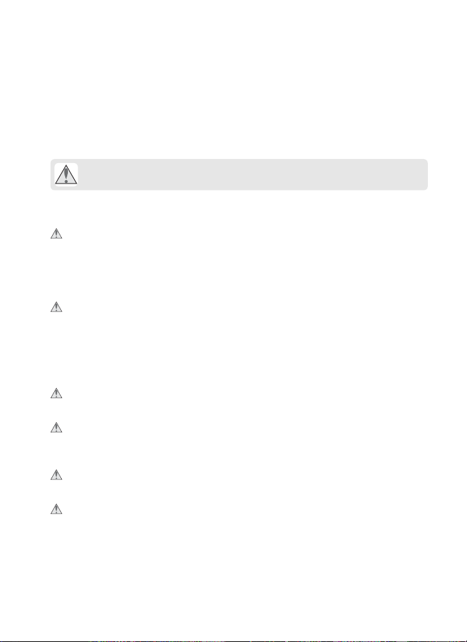
Parts of the WT-4
Parts of the W T-4
9
10
1 Power switch
...........................71, 82, 91, 103, 141
2 Antenna connector....................... 8
3 Status LEDs ............................... 3, 77
POWER (green/yellow),
LINK (green), ERROR (orange)
4 USB connector cover
...........................70, 81, 90, 102, 140
5 USB connector
...........................70, 81, 90, 102, 140
4, 5
23
6
7
8
6 Eyelet for strap
7 Connector cover
8 Battery chamber cover.................8
9 DC-IN connector
10 Ethernet connector
1
2
Introduction
Page 15
D The Antenna
Always use the supplied antenna with the WT-4. Use of other antennas
with this transmitter is prohibited by law.
A The POWER LED
When the WT-4 is on, the POWER LED glows green to indicate that the
battery is fully charged or that an AC adapter is connected. At battery
levels below 10%, it will blink green to warn that the battery requires
charging. When the WT-4 is turned off, the POWER LED briefly turns yellow
as the product powers down.
A Supplied Accessories
The following accessories are supplied with the WT-4 (batteries such as
the EN-EL3e and the battery chargers such as the MH-18a are not
supplied):
❏ User’s Manual (this manual)
❏ Warranty
❏ Software CD
❏ Antenna
❏ Case
❏ Strap
❏ USB cable
❏ USB cable clip for the D3
❏ USB cable clip for the D300
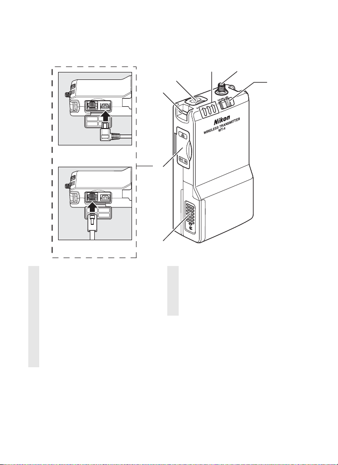
A USB Cable Clips for D3 and D300 Cameras
The USB cable clips prevent accidental disconnections. Attach as shown
below.
Parts of the W T-4
USB cable clip for the D3
USB cable clip for the D300
Introduction
3
Page 16

Supported Modes
The WT-4 connects the camera to wireless and Ethernet networks.
Supported Modes
Photographs on the camera can then be previewed on the
computer or transmitted to an ftp server or printer and the camera
controlled remotely from a computer. The WT-4 supports the
following modes:
Mode Host Description See
Tran sfer m ode
Thumbnail
select mode
PC mode Computer
Print mode Computer
Computer
or ftp server
Computer
Before data can be transferred over a wireless or Ethernet network,
the camera must be supplied with a network profile providing
information on the host computer or ftp server.
Upload new or existing
photographs to host.
Preview the photographs in internal
memory on the computer monitor
before upload.
Control camera from computer
using optional Camera Control Pro 2
software.
Print JPEG photographs on printer
connected to network computer.
pg. 70
pg. 79
pg. 90
pg. 97
4
Introduction
Page 17

A FTP Servers
Servers can be configured using standard ftp services available with
supported operating systems, such as IIS (Internet Information Services).
Connection to computers on other networks via a router, Internet ftp
connections and ftp servers running third-party software are not
supported.
A Ethernet Connection
The camera can not connect to a wireless LAN when an Ethernet cable is
connected. Before connecting to a wireless LAN, turn the WT-4 off and
disconnect the Ethernet cable.
No adjustments to wireless LAN settings are required when the camera is
connected to a LAN by an Ethernet cable.
A Routers
Connection to computers on other networks via a router is not supported.
A Firewall Settings
The WT-4 uses TCP ports 20 and 21 for ftp and TCP port 15740 and UDP
port 5353 when connecting to a computer. Computer firewalls must be
configured to allow access to these ports, as otherwise the computer may
not be able to access the WT-4.
A MAC Address Filtering
If the network using MAC address filtering, the filter must be supplied
with the MAC address of the WT-4. After attaching the WT-4 to the
camera, choose [Device info] > [MAC address] (pg. 172) from the camera
setup menu and note the wireless and Ethernet MAC addresses.
Supported Modes
Introduction
5
Page 18

Workflow
When using the WT-4 for the first time, follow the steps below to
set up the WT-4, install the required software, create a wireless
Workflow
network, and upload pictures to the computer.
1 Set up the WT-4 and install software (pp. 7–15).
1-1 Preparing the Camera
1-2 Preparing the WT-4
1-3 Installing Software
2 Configuring the Network (pp. 16–46).
• See pages pp. 17–25 for information on Windows Vista.
• See pages pp. 26–37 for information on Windows XP.
• See pages pp. 38–46 for information on Mac OS X.
3 Upload pictures.
Upload pictures to a host computer/Thumbnail Select Mode/PC Mode/Print Mode
(pp. 47–106).
3-1 Copying Network Profiles to the Camera
3-2 Connecting the WT-4
3-3 Uploading Images
Uploading Images to an ftp Se rver (pp. 107–149) .
3-1 Creating an ftp Server
3-2 Copying Network Profiles to the Camera
3-3 Connecting to the ftp Server
3-4 Uploading Images
6
Introduction
Page 19
Preparing the Camera
Before using the WT-4, set the camera [USB] option to [MTP/PTP],
insert a battery in the WT-4, and install the WT-4 Setup Utility and
Thumbnail Selector on the host computer.
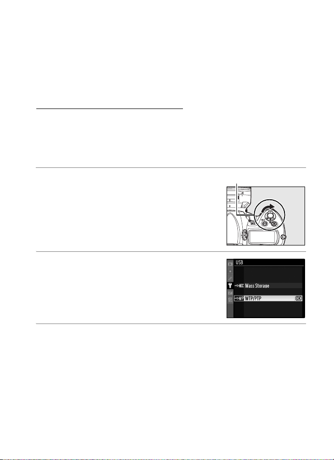
Choosing “MTP/PTP”
Before connecting the WT-4, set the camera [USB] option to [MTP/
PTP] as described below. Make sure that the camera battery is fully
charged or the optional AC adapter is connected. See the camera
manual for more information.
1 Turn the camera on.
Power switch
2 Select the [USB] in the camera setup
menu and choose [MTP/PTP]. See the
camera manual for details.
3 Turn the camera off.
Preparing the Camera
Introduction
7
Page 20
Preparing the WT-4
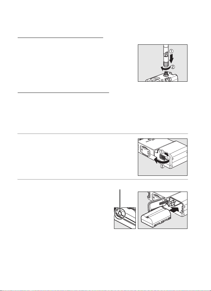
Attach the Antenna
Preparing the WT-4
Attach the supplied antenna to the WT-4 as
shown in the diagram.
Inserting the Battery
To prevent loss of power during setup or upload, use a fullycharged battery or an optional AC adapter. The WT-4 takes one
EN-EL3e rechargeable Li-ion battery; other batteries can not be
used. Note that the drain on the battery is increased when the
WT-4 is attached.
1 Open the battery chamber cover.
2 Using the side of the battery to
push the battery latch to one
side, slide the battery in until
the latch clicks into place. Be
sure the battery is in the
correct orientation. For safety
precautions and information
on charging the battery, see the battery and charger manuals.
8
Introduction
Battery latch
Page 21
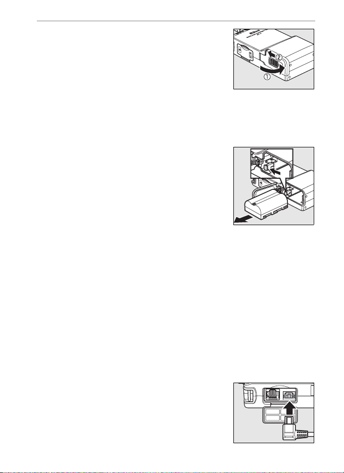
3 Close the battery-chamber cover.
A Removing the Battery
Being careful not to drop the battery, open the
battery chamber cover and remove the battery as
shown at right.
A Stand-By Mode
When disconnected from the camera, the WT-4 will turn off automatically
after the delay chosen for the [Auto power off] option in the [Wireless
transmitter] menu (pg. 173), reducing the drain on the battery. Note that
the WT-4 will not turn off automatically when transmitting data to a
computer in thumbnail select mode (pg. 79).
A Battery Level
The level of the battery inserted in the WT-4 can be determined by
connecting the WT-4 to the camera (pp. 70, 81, 90, 102, 140) and checking
the battery level using the [Battery info] option (pg. 172) in the camera
setup menu.
A The EH-6 AC Adapter
The optional EH-6 AC adapter can also be used to
power the camera when the WT-4 is connected.
Connect the DC plug on the AC adapter to the
WT-4 DC-IN connector, not to the camera.
Preparing the WT-4
Introduction
9
Page 22

Installing Software
This section describes how to install the WT-4 Setup Utility and
Installing Software
Thumbnail Selector. The WT-4 Setup Utility is used to copy
computer and printer profiles to the camera and is required when
configuring the camera for connection to a computer in transfer,
PC, and print modes (either the WT-4 Setup Utility or the camera
menus can be used for connection to ftp servers in transfer mode;
see page 175 for information on using the camera menus for ftp).
Thumbnail Selector required for thumbnail select mode (pg. 79).
Follow the steps below to install the WT-4 Setup Utility and
Thumbnail Selector under Windows Vista, Windows XP, or Mac OS X.
10
Introduction
Page 23

❏ System Requirements
Before using the WT-4 or WT-4 Setup Utility CD, confirm that your
system meets the following requirements:
Camera Nikon D3 and D300 digital single-lens reflex cameras
Power source
OS
Network
Miscellaneous
1. For the latest information on supported operating systems, see the Nikon
website for your area (pg. x).
2. Not required for connection to ftp servers.
3. Connect the camera directly to the computer. The camera may not function
as expected when connected via a hub, extension cable, or keyboard.
One EN-EL3e rechargeable Li-ion battery or EH-6 AC
adapter (available separately)
• To connect to a computer: Windows Vista Home Basic/
Home Premium/Business/Enterprise/Ultimate (32 bit),
Windows XP Service Pack 1 or later (Service Pack 2
recommended) or Mac OS X version 10.3.9 or 10.4.10
(Power PC G4/G5 and Intel CPUs only). Connection to
1
computers on other networks via a router is not
supported.
• To upload pictures to an ftp server: Operation has been
confirmed with Windows Vista Business/Enterprise/
Ultimate, Windows XP Professional Service Pack 1 or
later and Mac OS X version 10.3.9 or 10.4.10.
• Wir eless: Wireless LAN access point or computer with
built-in or external wireless LAN adapter (IEEE 802.11b,
802.11g, or 802.11a compliant).
• Ethern et: Ethernet cable and computer with built-in or
external Ethernet port (100 base-TX or 10 base-T)
• WT-4 Setup Utility: required to copy computer profiles to
camera.
2
• Thumbnail Selector : required for thumbnail select mode.
• CD-ROM drive: required when installing WT-4 Setup
Utility/Thumbnail Selector
• USB: the supplied USB cable and a computer with built-
in USB port are required when copying network
profiles to camera.
3
Installing Software
Introduction
11
Page 24
❏ Windows Vista/Windows XP
1 Start the computer and log in to an account with
administrator privileges.
Installing Software
2 Insert the supplied installer CD in a CD-ROM drive.
A Windows Vista
Under Windows Vista, an “AutoPlay” dialog will be displayed; click
[Run Welcome.exe].
displayed; click [Allow].
A language-selection dialog will be displayed.
A “User Account Control” dialog will then be
A If the Language Selection Dialog Is Not Displayed
If the installer does not start automatically, open the “Computer” or
“My Computer” window by selecting [Computer] or [My Computer]
from the [Start] menu (Windows Vista/XP) or by double-clicking the
[My Computer] icon on the desktop (Windows 2000 Professional),
and then double-click the CD-ROM icon.
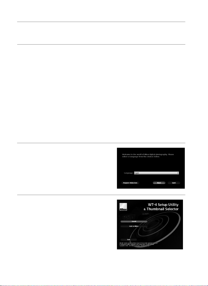
3 Select a language and click
[Next].
If the desired language is
not available, click [Region
Selection] to choose a different
region and then choose the
desired language.
4 Click [Install].
A Link to Nikon
Download trial versions of other
Nikon software from a Nikon website
or visit Nikon technical support
websites (Internet connection
required).
12
Introduction
Page 25

5 Select the software to be
installed and click [Install].
Follow the on-screen instructions
to complete installation.
6 The dialog shown at right will be
displayed when installation is
complete. Click [Yes] to close the
installer dialog.
7 Remove the installer CD from the CD-ROM drive. If prompted
to restart the computer, follow the on-screen instructions.
Installing Software
Introduction
13
Page 26
❏ Mac OS X
1 Start the computer and log in to an account with
administrator privileges.
Installing Software
2 Insert the supplied installer CD in a CD-ROM drive.
click the installer CD icon on the desktop, then double-click
the [Welcome] icon.
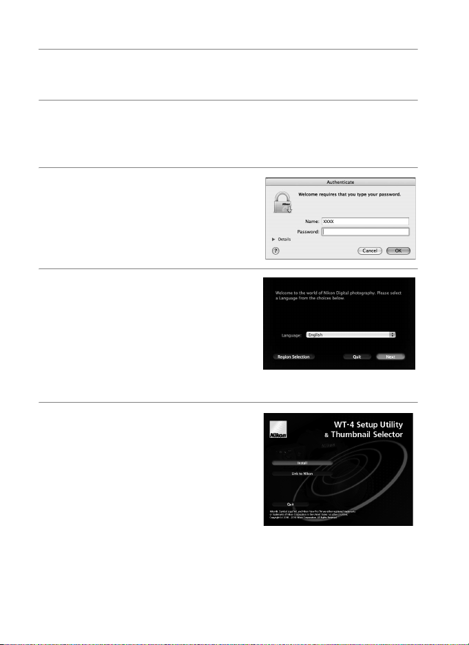
3 The dialog shown at right will be
displayed; enter an administrator
name and password and click
[OK].
4 A language selection dialog will
be displayed; select a language
and click [Next].
language is not available, click
[Region Selection] to choose a
different region and then choose
the desired language.
If the desired
5 Click [Install].
A Link to Nikon
Download trial versions of other
Nikon software from a Nikon website
or visit Nikon technical support
websites (Internet connection
required).
Double-
14
Introduction
Page 27
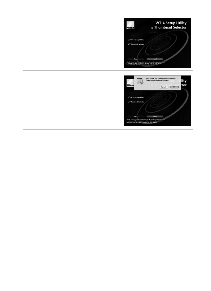
6 Select the software to be
installed and click [Install].
Follow the on-screen instructions
to complete installation.
7 The dialog shown at right will be
displayed when installation is
complete. Click [OK].
8 Remove the installer CD from the CD-ROM drive. If prompted
to restart the computer, follow the on-screen instructions.
Installing Software
A The WT-3 Setup Utility
If the WT-3 Setup Utility is installed or uninstalled after the WT-4 Setup
Utility/Thumbnail Selector is installed, the WT-4 Setup Utility/Thumbnail
Selector must be reinstalled.
Introduction
15
Page 28

Configuring the Network
This section describes how to create ad-hoc and infrastructure
Configuring the Network
networks under Windows Vista, Windows XP, and Mac OS X.
Windows Vista
Ad hoc Network pg. 17
Infrastructure Network pg. 21
Windows XP
Ad hoc Network pg. 26
Infrastructure Network pg. 32
Macintosh
Ad hoc Network pg. 38
Infrastructure Network pg. 42
A Connecting to Existing Wireless LANs
The WT-4 can also be used to connect to existing wireless LANs. Switch to
the existing network after creating a new network for use with the WT-4.
A Wireless Networks: Infrastructure Versus Ad-hoc
Wireless networks may be either infrastructure or ad-hoc.
• Infrastructure: Connection is via a
wireless LAN access point.
• Ad-hoc: A peer-to-peer wireless
network consisting solely of the
WT-4 and the host.
WT-4 Wireless
16
Introduction
LAN access
Host WT-4 Host
point
Page 29
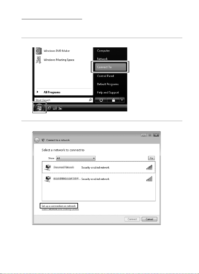
Windows Vista
❏ Creating an Ad Hoc Network
1 Click the [Start] orb and select [Connect To].
2 Click [Set up a connection or network].
Configuring the Network / Windows Vista / Creating an Ad Hoc Network
Introduction 17
Page 30
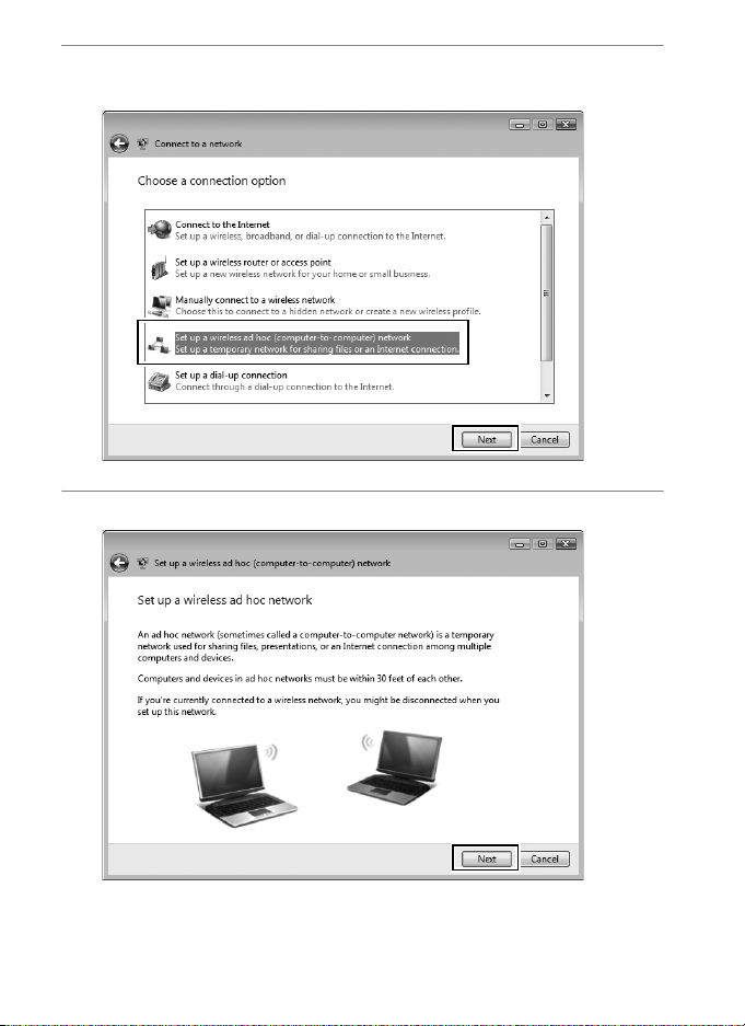
3 Select [Set up a wireless ad hoc (computer-to-computer)
network] and click [Next].
Configuring the Network / Windows Vista / Creating an Ad Hoc Network
4 Click [Next].
Introduction18
Page 31

5 After entering a network name and choosing security options
as described below, select [Save this network] and click [Next].
• Network name: Enter a name of up to 32 characters.
• Security type: Choose from [WEP] and [No authentication
(Open)].
• Security key/Passphrase: If [WEP] is selected for [Security type],
enter a security key. To enable 64-bit encryption, enter a
five-character ASCII or ten-digit hexadecimal key. To enable
128-bit encryption, enter a 13-character ASCII or 26-digit
hexadecimal key. ASCII keys may contain letters,
punctuation, and the numbers 0–9, hexadecimal keys the
numbers 0–9 and the letters a, b, c, d, e, and f.
Configuring the Network / Windows Vista / Creating an Ad Hoc Network
Introduction 19
Page 32

6 Click [Close].
Configuring the Network / Windows Vista / Creating an Ad Hoc Network
Network setup is now complete. Proceed to “Using the WT-4 with
a Computer” (pg. 47) or “Uploading Images to an ftp Server” (pg.
107).
Introduction20
Page 33

❏ Connecting to an Infrastructure Network
Procedures for connecting your computer to a wireless LAN access
point are described here.
Configuring the Wireless LAN Access Point
Following the instructions in the manual for the wireless LAN
access point, choose a network name (SS-ID), authentication,
encryption, security key, and key index.
Configuring the Host
1 Click the [Start] orb and select [Connect To].
Configuring the Network / Windows Vista / Connecting to an Infrastructure
Introduction 21
Page 34

2 Click [Set up a connection or network].
Configuring the Network / Windows Vista / Connecting to an Infrastructure
3 Select [Manually connect to a wireless network] and click
[Next].
If [Manually connect to a wireless network] is not displayed,
install the necessary driver software as described in the
documentation for the wireless LAN adapter.
Introduction22
Page 35

4 After entering a network name and choosing security options
to match those selected for the wireless LAN access point,
click [Next].
• Network name: Enter a name of up to 32 characters.
• Security type: Choose from [No authentication (Open)], [WEP],
[WPA-Personal], and [WPA2-Personal]. [WPA-Enterprise],
[WPA2-Enterprise], and [802.1x] can not be used with the
WT-4.
• Encryption type: The type of encryption available depends on
the options selected for [Security type]:
❏ None (open system): [None]
❏ WEP: [WEP]
❏ WPA, WPA2: [TKIP], [AES]
• Security key/Passphrase: If [WEP] is selected for [Security type],
enter a 5- or 13-character ASCII key or 10- or 26-digit
hexadecimal key. Entering a five-character ASCII or ten-digit
hexadecimal key enables 64-bit encryption, a 13-character
ASCII or 26-digit hexadecimal key 128-bit encryption. ASCII
keys may contain letters, punctuation, and the numbers 0–9,
hexadecimal keys the numbers 0–9 and the letters a, b, c, d,
e, and f. If [TKIP] or [AES] is selected for [Security type], enter
an ASCII key of 8 to 63 characters or a 64-digit hexadecimal
key.
Configuring the Network / Windows Vista / Connecting to an Infrastructure
Introduction 23
Page 36

Configuring the Network / Windows Vista / Connecting to an Infrastructure
5 Click [Connect to…].
Introduction24
Page 37

6 Confirm that [Connected] appears next to the network name
entered in Step 4 and click [Cancel].
Network setup is now complete. Proceed to “Using the WT-4 with
a Computer” (pg. 47) or “Uploading Images to an ftp Server” (pg.
107).
Configuring the Network / Windows Vista / Connecting to an Infrastructure
Introduction 25
Page 38

Windows XP
❏ Creating an Ad Hoc Network
Configuring the Network / Windows XP / Creating an Ad Hoc Network
1 Click [Start] and select [All Programs] > [Accessories] >
[Communications] > [Network Connections].
Introduction26
Page 39

2 Select [Wireless Network Connection] and click [Change
settings of this connection].
If a [Wireless Network Connection] icon is not displayed, install
the necessary driver software as described in the
documentation for the wireless LAN adapter.
Configuring the Network / Windows XP / Creating an Ad Hoc Network
Introduction 27
Page 40

3 Click the [Wireless Networks] tab.
Configuring the Network / Windows XP / Creating an Ad Hoc Network
If a third-party wireless connection program is installed, the
[Wireless Networks] tab will not be displayed. Choose
authentication, encryption, and a security key as described in
the documentation for the wireless LAN adapter. Make a note
of the security key, as it will be required when setting up the
camera.
4 Select [Use Windows to configure my wireless network
settings].
Introduction28
Page 41

5 Click [Add].
Configuring the Network / Windows XP / Creating an Ad Hoc Network
Introduction 29
Page 42

6 After entering a network name and choosing security options
as described below, select [This is a computer-to-computer
(ad hoc) network; wireless access points are not used] and
Configuring the Network / Windows XP / Creating an Ad Hoc Network
click [OK]. Do not select [The key is provided for me
automatically].
• Network name (SSID): Enter a name of up to 32 characters.
• Network Authentication: Choose from [Open] and [Shared].
• Data encryption: Choose from [WEP] and [Disabled].
• Network key : If [WEP] is selected for [Data encryption], enter a
security key. To enable 64-bit encryption, enter a fivecharacter ASCII or ten-digit hexadecimal key. To enable 128bit encryption, enter a 13-character ASCII or 26-digit
hexadecimal key. ASCII keys may contain letters,
punctuation, and the numbers 0–9, hexadecimal keys the
numbers 0–9 and the letters a, b, c, d, e, and f.
• Key index (advanced): If [WEP] is selected for [Data encryption],
choose a key index.
Introduction30
Page 43

7 Click [OK].
Network setup is now complete. Proceed to “Using the WT-4 with
a Computer” (pg. 47) or “Uploading Images to an ftp Server” (pg.
107).
Configuring the Network / Windows XP / Creating an Ad Hoc Network
Introduction 31
Page 44

❏ Connecting to an Infrastructure Network
Procedures for connecting your computer to a wireless LAN access
point are described here.
Configuring the Network / Windows XP / Connecting to an Infrastructure
Configuring the Wireless LAN Access Point
Following the instructions in the manual for the wireless LAN
access point, choose a network name (SS-ID), authentication,
encryption, security key, and key index.
Configuring the Host
1 Click [Start] and select [All Programs] > [Accessories] >
[Communications] > [Network Connections].
Introduction32
Page 45

2 Select [Wireless Network Connection] and click [Change
settings of this connection].
If a [Wireless Network Connection] icon is not displayed, install
the necessary driver software as described in the
documentation for the wireless LAN adapter.
Configuring the Network / Windows XP / Connecting to an Infrastructure
Introduction 33
Page 46

3 Click the [Wireless Networks] tab.
Configuring the Network / Windows XP / Connecting to an Infrastructure
If a third-party wireless connection program is installed, the
[Wireless Networks] tab will not be displayed. Choose
authentication, encryption, and a security key as described in
the documentation for the wireless LAN adapter. Make a note
of the security key, as it will be required when setting up the
camera.
4 Select [Use Windows to configure my wireless network
settings].
Introduction34
Page 47

5 Click [Add].
Configuring the Network / Windows XP / Connecting to an Infrastructure
Introduction 35
Page 48

6 After entering a network name and choosing security options
to match those selected for the wireless LAN access point,
remove the check from [This is a computer-to-computer (ad
Configuring the Network / Windows XP / Connecting to an Infrastructure
hoc) network; wireless access points are not used] and click
[OK].
• Network name (SSID): Enter a name of up to 32 characters.
• Network Authentication: Choose from [Open], [Shared], [WPA],
and [WPA-PSK].
• Data encryption: The type of encryption available depends on
the options selected for [Network Authentication]:
❏ Open, Shared: [WEP], [Disabled]
❏ WPA, WPA-PSK: [TKIP], [AES]
• Network key : If [WEP] is selected for [Data encryption], enter a
5- or 13-character ASCII key or 10- or 26-digit hexadecimal
key. Entering a five-character ASCII or ten-digit hexadecimal
key enables 64-bit encryption, a 13-character ASCII or 26digit hexadecimal key 128-bit encryption. ASCII keys may
contain letters, punctuation, and the numbers 0–9,
hexadecimal keys the numbers 0–9 and the letters a, b, c, d,
e, and f. If [TKIP] or [AES] is selected for [Data encryption],
enter an ASCII key of 8 to 63 characters or a 64-digit
hexadecimal key.
Introduction36
Page 49

7 Click [OK].
Network setup is now complete. Proceed to “Using the WT-4 with
a Computer” (pg. 47) or “Uploading Images to an ftp Server” (pg.
107).
Configuring the Network / Windows XP / Connecting to an Infrastructure
Introduction 37
Page 50

Macintosh
❏ Creating an Ad Hoc Network
Configuring the Network / Macintosh / Creating an Ad Hoc Network
1 Open [System Preferences] and click [Network].
Introduction38
Page 51

2 Choose [Network Port Configurations] from the [Show] menu.
3 Enable [AirPort], drag it to the top of the list, and click [Apply
Now].
Configuring the Network / Macintosh / Creating an Ad Hoc Network
Introduction 39
Page 52

4 Click the AirPort status icon in the menu bar and select [Turn
AirPort On].
Configuring the Network / Macintosh / Creating an Ad Hoc Network
5 Click the AirPort status icon in the menu bar and select [Create
Network...].
Introduction40
Page 53

6 After choosing a network name and channel and adjusting
encryption and password options as described below, click
[OK].
• Name: Enter a name of up to 32 characters.
• Channel: Choose a channel.
• Enable encryption (using WEP): Select this option to enable WEP
encryption.
• Password: If WEP encryption is enabled, enter a security key.
The length of the key depends on the option selected for
[WEP key]:
❏ [40-bit (more compatible)]: Enter a five-character ASCII or ten-
digit hexadecimal key.
❏ [128-bit]: Enter a 13-character ASCII or 26-digit
hexadecimal key.
ASCII keys may contain letters, punctuation, and the
numbers 0–9, hexadecimal keys the numbers 0–9 and the
letters a, b, c, d, e, and f.
• WEP key : Choose the length of the WEP key.
Configuring the Network / Macintosh / Creating an Ad Hoc Network
Network setup is now complete. Proceed to “Using the WT-4 with
a Computer” (pg. 47), “Uploading Images to an ftp Server” (pg.
107).
Introduction 41
Page 54

❏ Connecting to an Infrastructure Network
Procedures for connecting your computer to a wireless LAN access
point are described here.
Configuring the Network / Macintosh / Connecting to an Infrastructure
Configuring the Wireless LAN Access Point
Following the instructions in the manual for the wireless LAN
access point, choose a network name (SS-ID), authentication,
encryption, security key, and key index.
Configuring the Host
1 Open [System Preferences] and click [Network].
Introduction42
Page 55

2 Choose [Network Port Configurations] from the [Show] menu.
3 Enable [AirPort], drag it to the top of the list, and click [Apply
Now].
Configuring the Network / Macintosh / Connecting to an Infrastructure
Introduction 43
Page 56

4 Choose [AirPort] from the [Show] menu.
Configuring the Network / Macintosh / Connecting to an Infrastructure
5 Choose [Preferred networks] from the [By default, join] menu
and click [+].
Introduction44
Page 57

6 Enter the network name and other settings for the wireless
access point and click [OK].
• Network Name: Enter a name of up to 32 characters.
• Wireless Security: Choose from [None], [WEP Password], [WEP
40/128-bit hex], [WEP 40/128-bit ASCII], [WPA Personal], and
[WPA2 Personal]. [LEAP], [WPA Enterprise], [WPA2
Enterprise], and [802.1X WEP] can not be used with the
WT-4.
• Password: If WEP or WPA encryption is enabled, enter a
security key. The length of the key depends on the option
selected for [Wireless Security]:
❏ [WEP Password]: Enter a five- or thirteen-character key.
❏ [WEP 40/128 bit (hex)]: Enter a 10- or 26-digit hexadecimal
key. Hexadecimal keys may contain only the numbers 0–9
and the letters a, b, c, d, e, and f.
❏ [WEP 40/128 bit (ASCII)]: Enter a five- or thirteen-character key.
❏ [WPA-Personal], [WPA2-Personal]: Enter a key of 8 to 63
characters.
Configuring the Network / Macintosh / Connecting to an Infrastructure
Introduction 45
Page 58

7 Click [Apply Now].
Configuring the Network
Network setup is now complete. Proceed to “Using the WT-4 with
a Computer” (pg. 47) or “Uploading Images to an ftp Server” (pg.
107).
46
Introduction
Page 59

Using the WT-4 with a Computer
The WT-4 can be used in the following modes:
Transfer mode: Upload images to a computer.
Thumbnail select mode: Use the supplied Thumbnail Selector software
to preview the photographs on the camera as small thumbnail
images and select pictures for upload.
PC mode: Control the camera from a computer using Camera
Control Pro 2 (available separately).
Print mode: Print JPEG images from the camera to a printer
connected to a network computer.
The workflow for each of these modes is shown below.
1 Copying Network Profiles to the Camera (pg. 48).
• Ad Hoc Networks (pg. 48)
• Infrastructure Networks (
2 Upload pictures.
Upload pictures to a host computer (pp. 70–78).
2-1 Connecting the WT-4
2-2 Uploading Images
Thumbnail Select Mode (pp. 79–89).
2-1 Connecting the WT-4
2-2 Uploading Images
PC Mode (pp. 90–96).
2-1 Connecting to the Computer
2-2 Controlling the Camera
Print Mode (pg. 97–106).
2-1 Configuring the Printer
2-2 Printing Pictures
pg. 59)
Using the WT-4 with a Computer 47
Page 60

Copying Network Profiles to the Camera
Copying Network Profiles to the Camera / Ad Hoc Networks
Ad Hoc Networks
1 Connect the UC-E4 as shown below.
2 Turn the camera on.
Power switch
3 Turn the computer on and start the WT-4 Setup Utility.
• Windows: Double-click the [WT-4 Setup Utility] icon on the
desktop.
• Macintosh: Click the [WT-4WirelessSetup] icon in the Dock.
48
Using the WT-4 with a Computer
Page 61

4 The dialog shown below will be displayed; click [Next].
5 Select [Add/Edit profiles] and click [Next].
Copying Network Profiles to the Camera / Ad Hoc Networks
Using the WT-4 with a Computer
49
Page 62

A The “Select Action” Dialog
The other options in the “Select Action” dialog are described below. Note
that the camera need not be connected to a computer to choose a printer
or change the upload folder.
Copying Network Profiles to the Camera / Ad Hoc Networks
• Change password: The dialog shown at
right will be displayed. By default, no
password is required to change
device profiles using the WT-4 Setup
Utility. A password can be added by
selecting [Change password]. If the
camera is later connected to a
different computer, a password
prompt will be displayed. Once the
correct password has been entered,
the prompt will not be displayed
again. To change an existing
password, enter the old password before typing the new password. To
remove the password, select [Reset password (profiles will be lost)] and
click [Next]. Please note that resetting the password deletes all existing
device profiles from the camera. Click [Back] to exit without changing
password settings.
• Setup wireless printer: By default, the system default printer for the host
computer will be used when printing pictures. To choose a different
printer, select [Setup wireless printer] (pg. 97).
• Setup picture folder: The dialog shown
at right will be displayed. This screen
allows you to select the destination
folder when downloading images to
your computer in transfer mode.
Click the […] button to select the
destination for images uploaded to
the computer (the camera need not
be connected for this operation). The
default destination is the “WT-4”
folder in the “Pictures” (Windows
Vista/Mac OS X) or “My Pictures”
(Windows XP).
• Show it with ViewNX: If this option is selected, uploaded images will be
displayed in ViewNX when the connection with the WT-4 is
terminated. This option only available if ViewNX is installed.
50
Using the WT-4 with a Computer
Page 63

6 Select [Add new profile] and click [Next].
7 Enter the following information and click [Next]:
• Profile name: Enter a name of up to 16 characters.
• Profile type: Choose [Computer].
• Interface type: Choose [Wireless & Ethernet] for networks that
include wireless, or [Ethernet only] for Ethernet-only
networks.
Copying Network Profiles to the Camera / Ad Hoc Networks
Using the WT-4 with a Computer
51
Page 64

8 Select [Manual setup] and click [Next].
Copying Network Profiles to the Camera / Ad Hoc Networks
52
Using the WT-4 with a Computer
Page 65

A “Au tomatic Set u p ”
Choose [Automatic setup (recommended)] when using a new
network for the first time. The following dialog will be displayed;
select [Use Ad-hoc network] and click [Next] to proceed to Step 11
(pg. 57).
The [Automatic setup (recommended)] option can not be used with
existing network profiles, third-party wireless LAN adapters, networks
using static IP addresses, or Windows XP SP1 or Mac OS X.
Copying Network Profiles to the Camera / Ad Hoc Networks
Using the WT-4 with a Computer
53
Page 66

9 Enter the following information and click [Next].
• Network name (SSID): Enter a network name or choose from a
Copying Network Profiles to the Camera / Ad Hoc Networks
list of existing networks. Do not change the name if it is
supplied automatically.
• Communication mode: Select [Ad hoc].
• Channel: Select a channel. Note that if a matching SSID is
detected on a different channel, the WT-4 may change the
channel automatically.
• Authentication: Choose the type of authentication used on the
network. In ad-hoc mode, the camera supports open system
and shared key authentication.
• Encryption: The type of encryption used on the network.
Choose from [None] (open networks only), 64-bit WEP, and
128-bit WEP.
• Encryption key: If the network uses encryption, enter the
network key. The number of characters required depends
on the type of key used:
WEP (64-bit) WEP (128-bit)
Number of characters (ASCII) 513
Number of characters (hex) 10 26
• Key Index: If [WEP64] or [WEP128] is selected for [Encryption],
choose a key index (the default index is [1]). A key index is
not required when [None] is selected.
54
Using the WT-4 with a Computer
Page 67

Copying Network Profiles to the Camera / Ad Hoc Networks
Using the WT-4 with a Computer
55
Page 68

10
Select [Obtain IP address automatically] and click [Next].
• Obtain IP address automatically: Select this option if the network
Copying Network Profiles to the Camera / Ad Hoc Networks
is configured to supply IP addresses automatically. If the
network does not include a DHCP server, addresses will be
supplied by Auto IP (pg. 180).
• IP address: If the network is configured for manual IP
addressing, enter an IP address for the WT-4.
• Subnet mask: If the network is configured for manual IP
addressing, enter a subnet mask for the WT-4.
• Default gateway: If the network requires a gateway address,
select this option and enter the address supplied by the
network administrator. This option applies only if [FTP
Server] is selected for [Profile type] in Step 7.
• DNS Server: If a Domain Name Server exists on the network,
select this option and enter the address supplied by the
network administrator. This option applies only if [FTP
Server] is selected for [Profile type] in Step 7.
56
Using the WT-4 with a Computer
Page 69

11
Confirm that settings are correct and click [Next].
12
Select [Finish wizard] and click [Next].
Copying Network Profiles to the Camera / Ad Hoc Networks
Using the WT-4 with a Computer
57
Page 70

13
Turn the camera off and
disconnect the USB cable.
Copying Network Profiles to the Camera / Ad Hoc Networks
The network profile has now been copied to the camera. Proceed
to “Upload pictures to a host computer” (pg. 70), “Thumbnail
Select Mode” (pg. 79), “PC Mode” (pg. 90) or “Print Mode” (pg. 97).
58
Using the WT-4 with a Computer
Page 71

Infrastructure Networks
1 Connect the UC-E4 as shown below.
2 Turn the camera on.
Power switch
3 Turn the computer on and start the WT-4 Setup Utility.
• Windows: Double-click the [WT-4 Setup Utility] icon on the
desktop.
• Macintosh: Click the [WT-4WirelessSetup] icon in the Dock.
Copying Network Profiles to the Camera / Infrastructure Networks
Using the WT-4 with a Computer
59
Page 72

4 The dialog shown below will be displayed; click [Next].
Copying Network Profiles to the Camera / Infrastructure Networks
5 Select [Add/Edit profiles] and click [Next].
60
Using the WT-4 with a Computer
Page 73

A The “Select Action” Dialog
The other options in the “Select Action” dialog are described below. Note
that the camera need not be connected to a computer to choose a printer
or change the upload folder.
• Change password: The dialog shown at
right will be displayed. By default, no
password is required to change
device profiles using the WT-4 Setup
Utility. A password can be added by
selecting [Change password]. If the
camera is later connected to a
different computer, a password
prompt will be displayed. Once the
correct password has been entered,
the prompt will not be displayed
again. To change an existing
password, enter the old password before typing the new password. To
remove the password, select [Reset password (profiles will be lost)] and
click [Next]. Please note that resetting the password deletes all existing
device profiles from the camera. Click [Back] to exit without changing
password settings.
• Setup wireless printer: By default, the system default printer for the host
computer will be used when printing pictures. To choose a different
printer, select [Setup wireless printer] (pg. 97).
• Setup picture fold er: The dialog shown
at right will be displayed. This screen
allows you to select the destination
folder when downloading images to
your computer in transfer mode.
Click the […] button to select the
destination for images uploaded to
the computer (the camera need not
be connected for this operation). The
default destination is the [WT-4]
folder in the “Pictures” (Windows
Vista/Mac OS X) or “My Pictures”
(Windows XP).
•Show it with ViewNX: If this option is selected, uploaded images will be
displayed in ViewNX when the connection with the WT-4 is
terminated. This option only available if ViewNX is installed.
Using the WT-4 with a Computer
Copying Network Profiles to the Camera / Infrastructure Networks
61
Page 74

6 Select [Add new profile] and click [Next].
Copying Network Profiles to the Camera / Infrastructure Networks
7 Enter the following information and click [Next]:
• Profile name: Enter a name of up to 16 characters.
• Profile type: Choose [Computer].
• Interface type: Choose [Wireless & Ethernet] for networks that
include wireless, or [Ethernet only] for Ethernet-only
networks.
62
Using the WT-4 with a Computer
Page 75

8 Select [Manual setup] and click [Next].
Copying Network Profiles to the Camera / Infrastructure Networks
Using the WT-4 with a Computer
63
Page 76

A “Au tomati c Setup ”
Choose [Automatic setup (recommended)] when using a new
network for the first time. The following dialog will be displayed.
Select [Infrastructure network (recommended)] (if more than one
Copying Network Profiles to the Camera / Infrastructure Networks
infrastructure network exists, choose a network from the pull-down
menu) and click [Next] to proceed to Step 11 (pg. 68).
The [Automatic setup (recommended)] option can not be used with
existing network profiles, third-party wireless LAN adapters, networks
using static IP addresses, Windows XP SP1, Mac OS X, or computers
that are not configured for connection to a wireless LAN access point.
64
Using the WT-4 with a Computer
Page 77

9 Enter the following information and click [Next].
• Network name (SSID): Enter a network name or choose from a
list of existing networks. Do not change the name if it is
supplied automatically.
• Communication mode: Select [Infrastructure].
• Authentication: Choose the authentication used on the
network. In infrastructure mode, the camera supports WPAPSK, WPA2-PSK, open system, and shared key
authentication.
• Encryption: Choose the encryption used on the network. The
options available depend on the authentication used:
Open: None, 64- or 128-bit WEP Shared: 64- or 128-bit WEP
WPA-PSK: TKIP, AES WPA2-PSK: AES
• Encryption key: If the network uses encryption, enter the
network key. The number of characters required depends
on the type of key used:
WEP (64-bit) WEP (128-bit) TKIP, AES
Number of characters (A SCII) 5138–63
Number of characters (hex) 10 26 64
• Key Index: If [WEP64] or [WEP128] is selected for [Encryption],
choose a key index (the default index is [1]). A key index is
not required when [None] is selected.
Copying Network Profiles to the Camera / Infrastructure Networks
Using the WT-4 with a Computer
65
Page 78

Copying Network Profiles to the Camera / Infrastructure Networks
66
Using the WT-4 with a Computer
Page 79

10
Select [Obtain IP address automatically] and click [Next].
• Obtain IP address automatically: Select this option if the network
is configured to supply IP addresses automatically. If the
network does not include a DHCP server, addresses will be
supplied by Auto IP (pg. 180).
• IP address: If the network is configured for manual IP
addressing, enter an IP address for the WT-4.
• Subnet mask: If the network is configured for manual IP
addressing, enter a subnet mask for the WT-4.
• Default gateway: If the network requires a gateway address,
select this option and enter the address supplied by the
network administrator. This option applies only if [FTP
Server] is selected for [Profile type] in Step 7.
• DNS Server: If a Domain Name Server exists on the network,
select this option and enter the address supplied by the
network administrator. This option applies only if [FTP
Server] is selected for [Profile type] in Step 7.
Copying Network Profiles to the Camera / Infrastructure Networks
A Choosing an IP Address
Select [Obtain IP address automatically] if a DHCP server is present on the
network, otherwise deselect this option and enter an IP address different
from that of the computer or wireless LAN access point.
Using the WT-4 with a Computer
67
Page 80

11
Confirm that settings are correct and click [Next].
Copying Network Profiles to the Camera / Infrastructure Networks
12
Select [Finish wizard] and click [Next].
68
Using the WT-4 with a Computer
Page 81

13
Turn the camera off and
disconnect the USB cable.
The network profile has now been copied to the camera. Proceed
to “Upload pictures to a host computer” (pg. 70), “Thumbnail
Select Mode” (pg. 79), “PC Mode” (pg. 90), “Print Mode” (pg. 97).
Copying Network Profiles to the Camera / Infrastructure Networks
Using the WT-4 with a Computer
69
Page 82

Upload pictures to a host computer
Upload pictures to a host computer / Connecting the WT-4
Connecting the WT-4
Before connecting the WT-4, select [MTP/PTP] for the [USB] option
in the camera setup menu (pg. 7) and confirm that the host
computer is running and the user is logged in.
1 Turn the camera off an d inse r t the
memory card containing the pictures to
be sent (if the camera is equipped with
multiple memory card slots, the card can
be inserted into any slot).
Front
To access the network via Ethernet, connect the Ethernet
cable (pg. 2). Note that wireless transfer is disabled while an
Ethernet cable is connected. Disconnect the Ethernet cable
before accessing a wireless network. Turn the WT-4 off before
connecting or disconnecting the Ethernet cable.
2 Open the WT-4 USB connector cover and
connect the USB cable from the WT-4 to
the camera USB connector.
3 Turn the camera on.
70
Using the WT-4 with a Computer
Page 83

4 Select [Transfer mode] for the [Wireless
transmitter] > [Mode] option in the
camera setup menu (pg. 152).
5 A list of available connection profiles will
be displayed. Highlight the desired
profile and press J.
A Viewing Profile Information
Press the camera L (?) button to view
information on the selected profile.
6 Select [Wireless transmitter] > [Transfer
settings] and adjust settings as
described on pages pp. 169–170.
Upload pictures to a host computer / Connecting the WT-4
7 Turn on the WT-4.
8 Confirm that the selected profile is
displayed in green in the top level of the
wireless transmitter menu. For
information on what to do if an error is
displayed, see “Troubleshooting” (pg.
178).
Power switch
Using the WT-4 with a Computer
71
Page 84

A Ad-hoc Networks (Windows Vista)
To connect to an ad-hoc network using Windows Vista, turn the
WT-4 on and follow the steps below on the computer.
Upload pictures to a host computer / Connecting the WT-4
1 Click the “Start” orb and select [Connect To].
2 Select the network name (SSID) for the WT-4 and click
[Connect].
72
Using the WT-4 with a Computer
Page 85

3 Enter the network security key and click [Connect].
4 Click [Close].
Upload pictures to a host computer / Connecting the WT-4
Using the WT-4 with a Computer
73
Page 86

Uploading Images
1 Press the K button to view pictures on the memory card.
Upload pictures to a host computer / Uploading Images
Display the first picture to be sent in single-image playback or
highlight it in the thumbnail list.
2 While pressing the N button, press the
center of the multi selector (D3) or the J
button (D300). The image will be
marked with a white “send” icon and
transmission will begin immediately.
During upload, images are marked with
a green “sending” icon. Repeat this process to send additional
images (pictures will be sent in the order selected).
Images that have been successfully
uploaded are marked with a blue “sent”
icon. Images can be resent by pressing
the center of the multi selector while
pressing the N button (D3) or the J
button (D300) to change the blue “sent”
icon to a white “send” icon.
A D300 Retouch Options
When [Wireless transmitter] > [Mode] > [Transfer mode] is selected in the
camera setup menu and the WT-4 is on, the J button on the D300 is used
during playback to select pictures for upload, preventing it from being
used to select pictures for other operations, such as side-by-side
comparison. To restore normal operation, select another option for
[Wireless transmitter] > [Mode].
74
Using the WT-4 with a Computer
Page 87

3 Turn the WT-4 off and wait for the
POWER LED (pg. 3) to turn from green to
yellow and then go out. Disconnect the
USB cable. The destination folder
selected in the Setup Utility (pg. 50) will
open automatically when the
connection between the computer and
the WT-4 is terminated.
❏ Interrupting Transmission
To cancel transmission of images marked with a white “send” icon
or green “sending” icon, select the images during playback and
press the center of the multi selector while pressing the N button
(D3) or the J button (D300). The icon will be removed. Any of the
following actions will also interrupt transmission:
• Turning the camera or WT-4 off
• Selecting [Yes] for [Wireless transmitter] > [Transfer
settings] > [Deselect all]
D During Upload
Do not remove the memory card or disconnect the Ethernet cable during
upload.
A Voice Memos
Voice memos can not be uploaded separately, but will be included when
associated pictures are transmitted. Voice recordings can not be selected
for upload.
A Loss of Signal
Transmission may be interrupted if the signal is lost (pg. 77). Transmission
can be resumed by turning the WT-4 off and then on again.
A Turning the Camera Off
“Send” marking will be saved if the camera or WT-4 is turned off while
transmission is in progress. Transmission of images marked with a “send”
icon will resume when the camera or WT-4 is turned on.
Using the WT-4 with a Computer
Upload pictures to a host computer / Uploading Images
75
Page 88

❏ Transfer Status
During playback, the status of images selected for upload is shown
as follows:
Upload pictures to a host computer / Uploading Images
a: “Send”
Images that have been selected for upload
are marked with a white
a icon.
b: “Sending”
A green
b icon is displayed during upload.
c: “Sent”
Images that have been uploaded
successfully are marked with a blue
c icon.
A Removing the “Send,” “Sending,” and “Sent” Icons
“Send,” “sending,” and “sent” icons can be removed from all images by
selecting [Yes] for [Wireless transmitter] > [Transfer settings] > [Deselect
all?] (pg. 170).
76
Using the WT-4 with a Computer
Page 89

❏ Network Status
The status of the link between the host and the WT-4 is shown by
the status LEDs and by the display in the top level of the wireless
transmitter menu.
The Status LEDs
The POWER LED lights when the WT-4 is on.
Signal quality is shown by the LINK LED: the
faster the LED blinks, the better the signal
and the faster data can be transmitted. The
ERROR LED blinks to show that an error has
occurred.
Status POWER LINK ERROR
WT-4 off
USB cable not connected
Connecting to host
Waiting to send or sending data
Connection error
WT-4 hardware or battery malfunction
I (off ) I (off) I (off)
K (on) I (off ) I (off)
K (on) K (on) I (off)
K (on) H (blinks) I (off )
H (blinks) I (off) H (blinks)
H (blinks) H (blinks) H (blinks)
Status LEDs
Upload pictures to a host computer / Uploading Images
Using the WT-4 with a Computer
77
Page 90

The Status Display
Network status can also be viewed in the top level of the wireless
transmitter menu.
Upload pictures to a host computer / Uploading Images
Status area: The status of the
connection to the host. The host
name is displayed in green when a
connection is established. While files
are being transferred, the status
display shows “Now sending”
e, f: The estimated
time required to
send the remaining
images.
Battery level: A fivelevel display
showing the charge
state of the battery
in the WT-4.
followed by the nam e of the fi le bei ng
sent. Any errors that occur during
transfer are also displayed here.
Signal strength: This icon shows w ireless
signal strength. It is displayed in red
when no signal can be detected. For
maximum signal strength, ensure a
clear line of sight between the WT-4
antenna and the wireless LAN adapter
or access point. A d icon is displayed
when the WT-4 is connected via
Ethernet.
78
Using the WT-4 with a Computer
Page 91

Thumbnail Select Mode
Photographs taken with [Thumbnail select mode] selected for
[Mode] are saved both to the camera memory card and to the
WT-4 wireless transmitter’s internal memory.
previews of the copies on the WT-4 are transmitted to the
computer for display in the supplied Thumbnail Selector software,
making it possible to select photographs for transfer to the
computer.
Small thumbnail
Example
Suppose multiple photographers using cameras equipped with
WT-4 wireless transmitters are stationed around the field at a
soccer game, recording the action from different angles.
Thumbnail previews are transmitted over a wireless network to a
computer, where Thumbnail Selector can display photographs
from up to five cameras in real time.
select the thumbnails they prefer and upload only these selected
images to the computer.
Workers at the computer can
Thumbnail Select Mode / Uploading Images
Using the WT-4 with a Computer
79
Page 92

Thumbnail Selector
Thumbnail Selector displays the images stored in the WT-4 as
small thumbnail previews.
Thumbnail Select Mode / Uploading Images
can be previewed instantly and selected for upload as desired.
Photographs from up to five cameras
more information, see the online help for Thumbnail Selector.
A Internal Memory
The WT-4 is equipped with 1 GB of internal memory.
photographs are stored; if memory is full, the oldest photographs will be
deleted as necessary to make room for new pictures. The photographs on
the WT-4 are not affected when a new memory card is inserted in the
camera, and memory cards can be freely exchanged without concern for
whether the images they contain have been uploaded to the computer.
Photographs can be deleted from the WT-4 by formatting internal
memory as described on page 173. All photographs stored in internal
memory will be deleted.
If a large number of photographs are taken in a single burst, some time
may be required to copy the pictures to internal memory.
photographs remaining to be copied can be viewed by selecting [Wireless
transmitter] in the setup menu after shooting.
The camera memory card access lamp will light while photographs are
being copied to internal memory.
memory, do not remove the battery from the camera or WT-4 or
disconnect the AC adapter or USB cable while the access lamp is lit. If the
WT-4 is turned off while the access lamp is lit, the WT-4 will remain on until
all pictures have been transferred to internal memory.
To prevent damage to internal
Only the most recent
The number of
For
80
Using the WT-4 with a Computer
Page 93

Connecting the WT-4
Before connecting the WT-4, select [MTP/PTP] for the [USB] option
in the camera setup menu (pg. 7) and confirm that the host
computer is running.
1 Turn the camera off and insert the
memory card containing the pictures to
be sent (if the camera is equipped with
multiple memory card slots, the card can
be inserted into any slot).
Front
To access the network via Ethernet, connect the Ethernet
cable (pg. 2). Note that wireless transfer is disabled while an
Ethernet cable is connected. Disconnect the Ethernet cable
before accessing a wireless network. Turn the WT-4 off before
connecting or disconnecting the Ethernet cable.
2 Open the WT-4 USB connector cover and
connect the USB cable from the WT-4 to
the camera USB connector.
Thumbnail Select Mode / Connecting the WT-4
3 Turn the camera on.
Using the WT-4 with a Computer
81
Page 94

4 Select [Thumbnail select mode] for the
[Wireless transmitter] > [Mode] option in
the camera setup menu (pg. 152).
Thumbnail Select Mode / Connecting the WT-4
5 A list of available connection profiles will
be displayed. Highlight the desired
profile and press J.
A Viewing Profile Information
Press the camera L (?) button to view
information on the selected profile.
6 Turn on the WT-4.
7 Confirm that the selected profile is
displayed in green in the top level of the
wireless transmitter menu. For
information on what to do if an error is
displayed, see “Troubleshooting” (pg.
178).
82
Using the WT-4 with a Computer
Power switch
Page 95

A Ad-hoc Networks (Windows Vista)
To connect to an ad-hoc network using Windows Vista, turn the
WT-4 on and follow the steps below on the computer.
1 Click the “Start” orb and select [Connect To].
2 Select the network name (SSID) for the WT-4 and click
[Connect].
Thumbnail Select Mode / Connecting the WT-4
Using the WT-4 with a Computer
83
Page 96

3 Enter the network security key and click [Connect].
Thumbnail Select Mode / Connecting the WT-4
4 Click [Close].
84
Using the WT-4 with a Computer
Page 97

Uploading Images
1 Connect the WT-4 as described above and select [Thumbnail
select mode] for [Wireless transmitter] > [Mode]. Thumbnail
Selector will start automatically.
2 Choose a camera in the [Source] panel. Small previews of the
pictures on the WT-4 will appear in the thumbnail area.
[Source] Panel
thumbnail
area
A Starting Thumbnail Selector
To start Thumbnail Selector manually:
• Wi ndows: Double-click the [Thumbnail Selector] shortcut on the desktop
or display the Start menu and select [Thumbnail Selector] from the
program list.
• Macintosh: Click the [Thumbnail Selector] icon in the Dock (if available) or
open the “Applications/Nikon Software/Thumbnail Selector” folder and
double-click the [Thumbnail Selector] icon.
A The Camera Clock
At default settings, the computer and camera clocks will be synchronized
then the host computer detects the camera. To prevent the camera clock
from being reset, open the [Preferences] panel and remove the check
from [Synchronize camera date and time to computer when camera is
connected (supported cameras only)].
Using the WT-4 with a Computer
Thumbnail Select Mode / Uploading Images
85
Page 98

3 Right click the camera icon in the [Source] panel and select
[Edit camera information]. Enter a name and choose a label for
the camera and then click [OK]. The selected label will be
Thumbnail Select Mode / Uploading Images
displayed on the images in the thumbnail list.
4 Take photographs. The new pictures will be displayed in the
thumbnail list.
5 Click [Start Transfer]. The button will change to [Stop Transfer].
86
Using the WT-4 with a Computer
Page 99

6 Click the thumbnail for a photograph that you wish to transfer
to the computer. The selected thumbnail will be highlighted.
2
Click the selected thumbnail again or press the spacebar. A
check-mark will appear on the selected photograph and
upload will begin immediately.
2
At default settings, photographs are uploaded to a “WT-4”
folder in the “Picture” (Windows Vista/Mac OS X) or “My
Pictures” (Windows XP) folder. For more information on using
Thumbnail Selector, see online help.
7 Turn the WT-4 off when transfer is
complete.
3) to turn from green to yellow and
then go out, and then disconnect the
USB cable.
Wait for the POWER LED (pg.
Thumbnail Select Mode / Uploading Images
Using the WT-4 with a Computer
87
Page 100

❏ Network Status
The status of the link between the host and the WT-4 is shown by
the status LEDs and by the display in the top level of the wireless
Thumbnail Select Mode / Uploading Images
transmitter menu.
The Status LEDs
The POWER LED lights when the WT-4 is on.
Signal quality is shown by the LINK LED: the
faster the LED blinks, the better the signal
and the faster data can be transmitted. The
ERROR LED blinks to show that an error has
occurred.
Status POWER LINK ERROR
WT-4 off
USB cable not connected K (on) I (off ) I (off)
Connecting to host K (on) K (on) I (off)
Waiting to send or sending data K (on) H (blinks) I (off)
Connection error H (blinks) I (off ) H (blinks)
WT-4 hardware or battery malfunction H (blinks) H (blinks) H (blinks)
I (off ) I (off) I (off)
Status LEDs
88
Using the WT-4 with a Computer
 Loading...