

Page 1
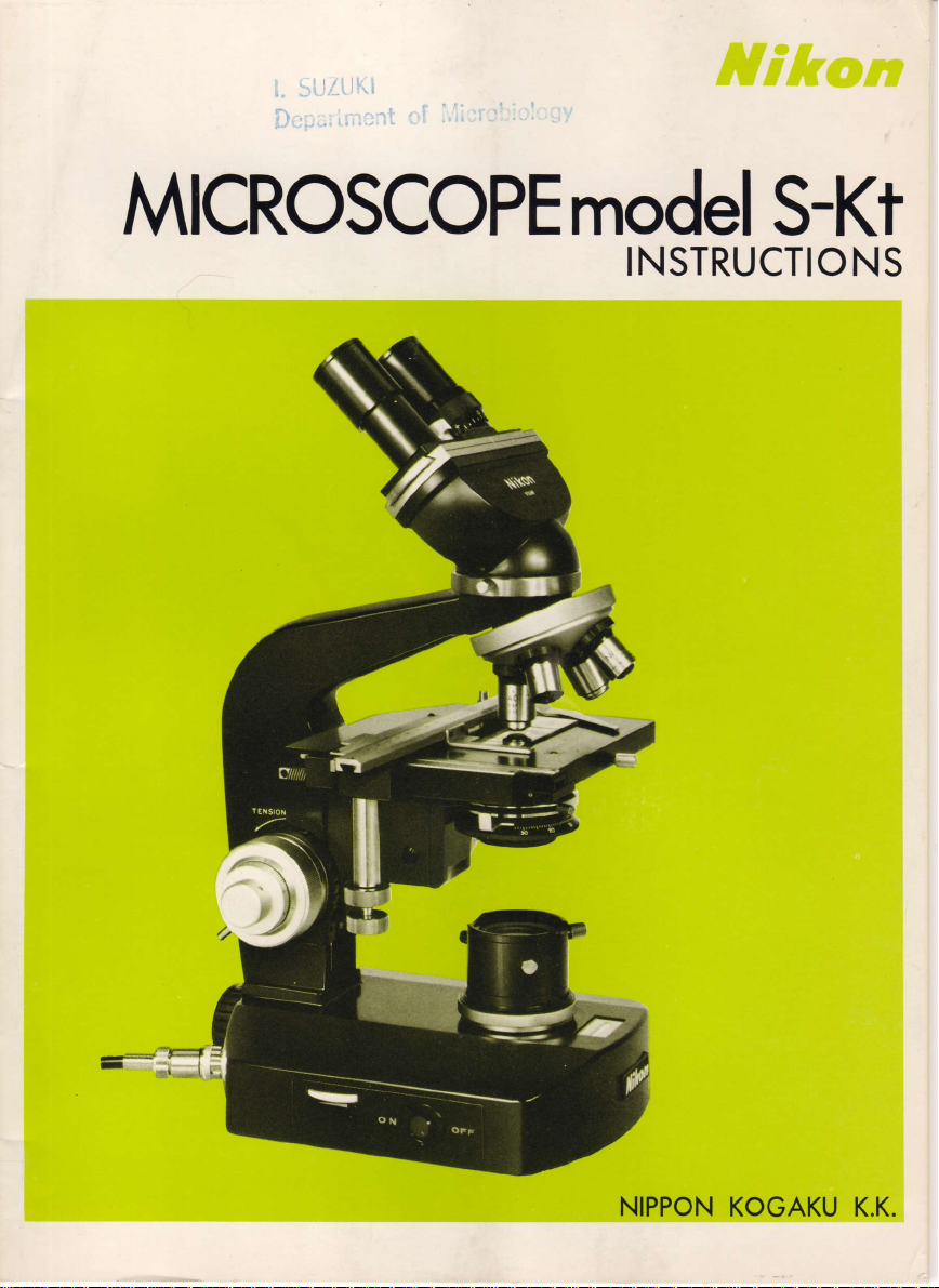
MICROSCOPEmodeI
S-Kt
INSTRUCTIO
NS
NIPPON
KOGAKU K.K.
Page 2
I
CONTENTS
NOMENCLATURE
1.
ATTACHINGTHELENSES
2.
(1)
Mounting
(2)
Mounting the Eyepieces
(3)
Mounting
ILLUMINATION
3.
(1)
Condenser lris Diaphragm
(z
LightSource...
(3
Condenser
(4
Brightness
(5
Preparation
(6
Observation
Photom
17
(8)
F ilters
(9)
lllumination for Very Low Magnifications
(10)
Replacing the
4.
FOCUSTNG
(1)
Focusins
(21
EyepieceAdjustment
(3)
CoarseFocusing .......1a
(41
PresetDevice
(5)
FineFocusing
(6)
Oil lmmersion
(Vl
ExchangingStages
MOVTNG
5.
(1)
Rectangular Mechanical
Circular
l2l
PHOTOMICROGRAPHY
6.
7.
COMBINATIONS.
(1)
lnterchangeableEyepieceTubes
(21
lnterchangeableStages
OBJECTIVES, EYEPIECES, CONDENSERS ......21
8.
(1)
Objectives ......2i
(21
Eyepieces
(3)
Combinations of
(4)
Condensers .. .....25
(5)
llluminationSystem .....25
CAUTIONS IN HANDLING AND MAINTENANCE -27
9.
the
Objectives . .
. . .
the
Condenser . .
..
Focusing
Adjustment
and Adjustment for
icrography
Bulb
Knob
.
Observation
;
. . ...
nOiusireni........... ....13
........14
.....i........15
THE SPECTMEN
Gliding Stage
Objectives and
THE
ON
Stage
"C"
STAGE
"R"
Eyepieces
........20
.......6
....
. .
....13
...14
. ..1b
. . . . .
. . .
. . . .
....18
...19
......20
. ....29
. .
6
l
7
8
g
g
g
q
f 6
p
n
13
tf
16
16
17
23
Page 3
E
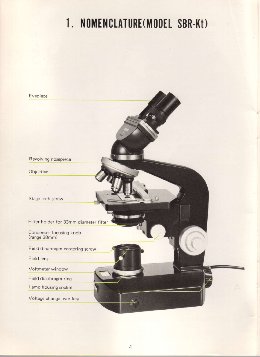
yep
iece
I. NOMENCTATURE(]YIODEL
SBR.I{I)
Revolving
Objective
Stage lock
Filter
holder for
Condenser
(range
2Bmm)
Field
diaphragm
F
ield
lens
Voltmeter
Field
diaphragm
Lamp
housing
Voltage
change-over
nosepiece
screw
33mm
focusing
centering
window
ring
socket
diameter filter
knob
screw
key
Page 4
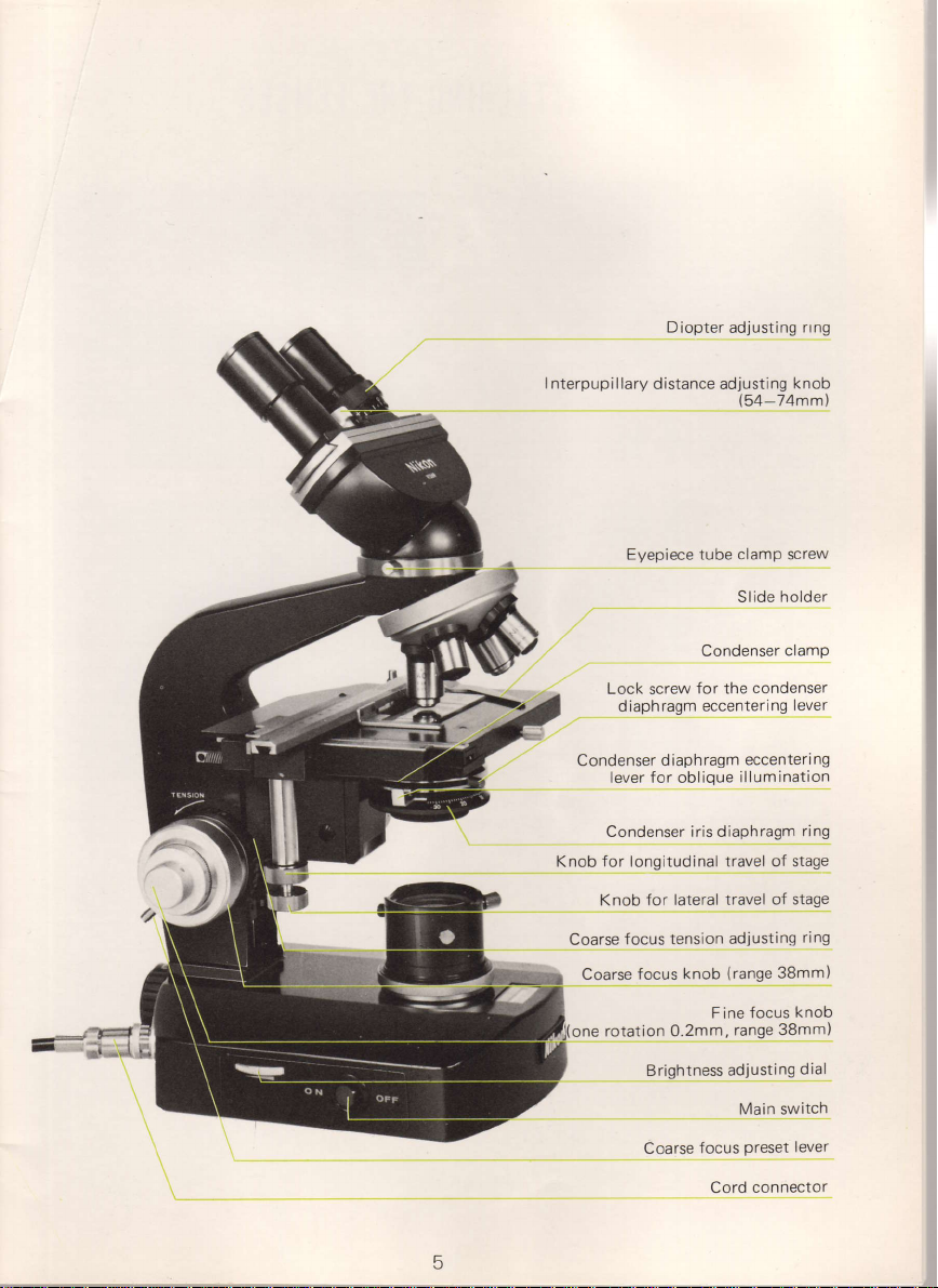
Diopter
adjusting
rrng
I nterpupillary
Condenser
Knob for longitudinal travel of stage
Coarse
Coarse
distance adjusting
Frrcnicec tilhc clamn
Condenser
Lock
d iaph
lever for oblique
Condenser iris diaphragm
Knob
focus
for the
screw
ragm eccentering
ragm eccenteri
diaph
for lateral travel
tension adjusting
(range
knob
focus
knob
(54-74mm)
Screw
holder
Slide
clamP
condenser
lever
illumination
of stage
38mm)
ng
ring
ring
fi=
rotation 0.2mm,
one
Brightness
Coarse
F
ine
adjusting
focus
Cord connector
knob
focus
range 38mm)
dial
Main switch
lever
Preset
5
Page 5
2.
ATTAC]IINO
THT LENSTS
Before attaching
eyepiece
outer
mark may
contrast.
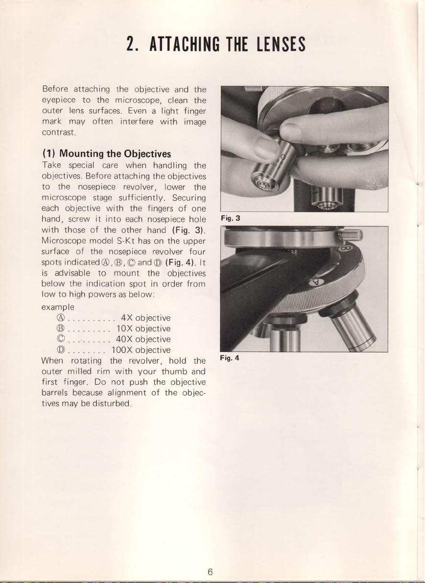
(1)
Take
objectives.
to the nosepiece revolver,
microscope
each
hand,
with
Microscope
sr rr face of the noseniece
spots
is advisable to mount
below the indication
low to high
to
lens
Mounting
special care when
Before attaching
objective with the fingers
screw
those of the other hand
indicated
the objective
microscope,
the
surfaces.
often
stage sufficiently.
it into
model
powers
Even
interfere with
the
Objectives
each nosepiece
has
S-Kt
@), O
as
below:
and
spot
@,
a
handling
the objectives
on the upper
revolver
O
the
in
and the
clean
the
light finger
image
the
lower the
Securing
of
one
hole
(Fig.
3)
f
our
(Fig.
4) lt
objectives
from
order
example
@
@
o
@..
When
outer
first finger.
barrels because alignment of the objec-
maV
tives
.... 4xobjective
....10Xobjective
....40Xobjective
. ...looxobjective
rotating
milled rim
Do
be disturbed
the
with
not
revolver,
your
push
hold the
thumb
the objective
and
Fis.
Fig'
3
4
Page 6
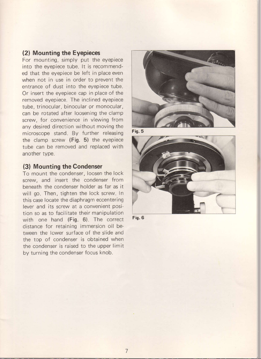
(2)
Mounting
For mounting, simply
into the eyepiece tube.
ed that the eyepiece be
not in use
when
entrance
Or
removed
tube,
can be
screw,
anv desired
microscope stand.
the clamp screw
tube can
another
of dust into
the eyepiece cap
insert
eyepiece. The inclined
trinocular, binocular
rotated
for convenience
direction
be
type.
Eyepieces
the
in order to
loosening the
after
without moving
By
(Fig.
removed
put
lt is
left in
the eyepiece tube.
in viewing
further releasing
5) the eyepiece
and
eyepiece
the
recommend-
place
even
prevent
place
in
gr
replaced
of the
eyepiece
monocular,
clamp
from
with
the
the
Fis. 5
(3)
Mounting the
To mount the
insert
screw.
beneath
will
this
lever
tion so as
with
distance
tween
the
the condenser
by turning
and
the condenser
go.
Then, tighten
locate the diaphragm
case
and its screw
facilitate their manipulation
to
one hand
for retaining immersion
the lower surface
too of condenser
the condenser
Gondenser
condenser,
(Fig.
raised to the upper
is
loosen the
the condenser
holder as
lock
the
eccentering
convenient
at a
6). The
the
of
is obtained
focus
lock
from
far as it
screw.
posi-
correct
oil
slide
when
limit
knob.
In
Fis.6
be-
and
Page 7
I TTlJ]t|I]{ATION
3.
Resolution
affected
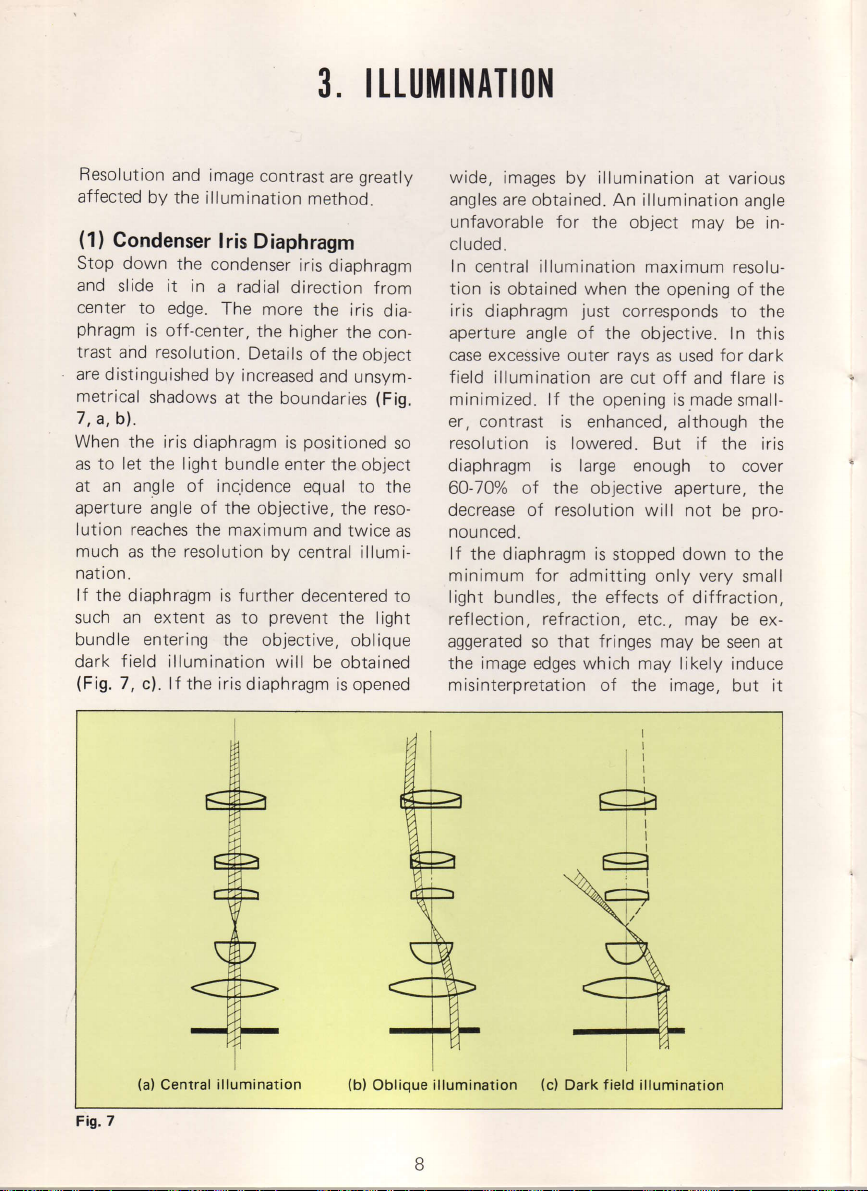
(1)
Stop
and
center
phragm
trast and resolution.
are
distinguished
metrical
7,a,bl.
When
as to let
at an angle of inc.idence
aperture angle of
lution reaches
much as the resolution
natron.
lf the diaphragm is further
such an extent
bundle entering
dark
(Fig.
and
image
by the
illumination
Condenser
down
slide it in
to edge.
is off-center,
shadows
the iris diaphragm
the light bundle enter
field
7,
c). lf the iris
lris
Diaphragm
the
condenser
a radial
The
the
Details
by increased
at the
the objective,
the maximum
to
as
the objective,
illumination
diaphragm
contrast
iris
direction
more
higher
boundaries
is
by central
decentered to
prevent
will
greatly
are
method.
diaphragm
from
the iris
of the object
and
positioned
equal
and twice
be
dia-
the
con-
unsym-
(Fig.
so
the object
to the
reso-
the
as
illumi-
light
the
oblique
obtained
is opened
wide, images
angles
unfavorable for
cl
uded.
In
tion is
iris
aperture angle of the objective.
case
field
minimized. lf the
er,
resolution
diaphragm is large enough
60-700/0 of the objective
decrease
nounceo.
lf
the diaphragm is
minimum
light
reflection, refraction,
aggerated
the
misinterpretation of
obtained.
are
central illumination
obtained when the
diaphragm
excessive outer rays
illumination
contrast is enhanced,
of
for
bundles, the
so
image
edges which may likely
illumination
by
An illumination
the object may
maximum resolu-
just
are cut off
opening
is lowered.
resolution
admitting only very
effects
that fringes
opening of the
corresponds
as used
ismade
although the
But
aperture, the
will not
stopped down to the
of diffraction,
etc., may
may be
the image, but it
at
for
and
if
the iris
to cover
be
various
angle
be in-
to the
In this
dark
flare
is
small-
pro-
small
be ex-
seen at
induce
Fig.7
(a)
Central
illumination
(b)
Oblique
illumination
(c)
Dark field illumination
Page 8
may be effective
(e.9.
definition of the
unstained
(2)
As already
plays
for microscopy.
phragm
numerical aperture
equal
in order
ln
light
by
down
will bring
cases.
phragm
pupil)
by
after
the
user,
procedure,
adjusting
satisfactory
obta
lf high
high
nation
suited
Fig. I
specimens) .
Light Source
discussed,
important
an
should
to that of
to obtain
practice,
whlch
closing
the aperture
to 60-700/o
about
The coincidence
aperture
the objective
of
looking down
removing the
diaphragm
however,
and obtain
the
i ned
.
resolution and, at
contrast are
may be
for lightly stained specimens,
for
general
the
role
principle,
In
be so adjusted
of the
the objective being
maximum
however,
would
diaphragm
distinctness
effective. This
keeping
reduce image contrast
of that
good results in most
the aperture
with
can be ascertained
the
eyepiece and
slowly.
may
dispense
the same
desirable,
special
of the
of condenser
occasions
structure of
iris diaphragm
illumination
in
the dia-
the
that
condenser
used,
resolution.
out stray
condenser
of the objective
dia-
(exit
microscope tube
closing
experienced
An
this
with
result by
opening
the image
of
the same
oblique
until
time,
illumi-
is especially
trans-
parent phase
with this
contrast
may
be
of illumination,
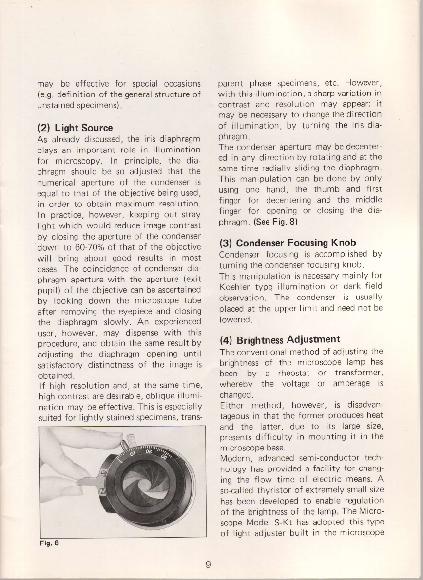
phragm.
condenser
The
in
ed
any
time
same
manipulation
This
is
is
one
using
for decentering
finger
for opening
finger
phragm.
(3)
Condenser
Condenser
turning
manipulation
This
Koehler
observation.
placed
at
lowered.
(4)
Brightness
The conventional
brightness
by a
been
whereby
cnangeo.
Either method,
tageous
the
and
presents
microscope
Modern, advanced
nology has
the
ing
so-called
has been
brightness
of the
Model
scope
light adjuster
of
specimens,
illumination,
resolution
and
necessary to
direction
radially sliding
hand,
(See
Fig.8)
a sharp
change
turning
by
aperture
rotating
by
can be
the thumb
or closing
Focusing
focusing
the condenser
type
The
the upper
is accomplished
focusing
is necessary
illumination
condenser
limit and
Adjustment
method
of the
the
in
that
latter,
difficulty
base.
flow time
thyristor
developed
microscope
rheostat or
voltage
however,
former
the
due
mounting
in
semi-conductor
provided a facility
of electric
of extremely
to
the
of
has
S-Kt
built
However,
etc.
variation
may appear;
the direction
iris dia-
the
may be decenter-
at the
and
the diaphragm.
and
the
only
first
middle
the
dia-
done by
and
Knob
by
knob.
for
mainly
or dark
of adiusting
transformer,
or amPerage
is disadvan-
produces
to its
enable
lamp, The
adopted
in the
field
is usually
not
need
the
lamp has
heat
large size,
in the
it
tech-
for chang-
means. A
size
small
regulation
Micro-
type
this
microscope
in
it
be
is
Page 9
Dase.
Turn the
side
voltmeter
age,
the direction of the
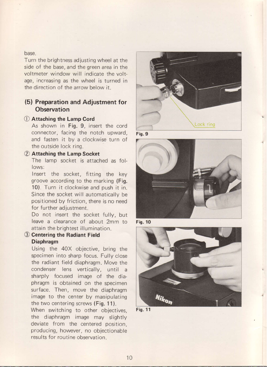
(5)
brightness ad
of the
base, and the
window will indicate
increasing
as the wheel
arrow below it.
Preparation
and Adjustment for
Observation
Attaching the Lamp
O
As shown in Fig.
connector, facing
fasten
and
the outside
Attaching
@
The lamp
it
by a clockwise
lock ring.
the Lamp
socket
lows:
Insert
groove
the
socket,
according to
10). Turn it clockwise
the
Since
positioned
for further
Do not insert
leave
attain the
Centering
O
socket will
f riction,
by
justment.
ad
the
a clearance
brightest illumination.
the
Radiant Field
Diaphragm
Using the
specimen
the radiant field
condenser
sharply
phragm
40X objective,
into
sharp
diaphragm. Move
lens
focused
is
obtained
surface. Then, move
image to the
the two centering
When
switching to other
the
diaphragm image
deviate
producing,
results for
center
from
the
however,
routine
screws
justing
wheel
green
area
the volt-
is turned in
Cord
insert
9,
the
notch
the cord
upward,
turn of
Socket
is
attached
fitting
the
the markinS
push
and
automatically
there is
socket
of
about 2mm to
no
fullv,
bring the
focus.
Fully
vertically,
image
on the
of the
specimen
the
diaphragm
until
by manipulating
(Fig.
1 1).
objectives,
may
slightly
centered
no
position.
objectionable
observation.
at the
in
the
fol-
as
key
(FiS.
it
need
but
close
the
dia-
in
be
Fis.
9
Fig. 10
a
11
Fig.
10
Page 10

(6)
Observation
The microscope
uniformly bright illumination ranging
from
the 4X objective up
immersion
of changing the illumination
interference or
tion, turn
(Fig.
Note that
for
tion with the
cause of insufficient
It can be used
up to a total
when the illumination ls
maximum
(7)
Compared with
scope, the
graphs
In monochromatic
contrast
green
In
Fig. 13, the dial of
adjuster at the
base
PHOTO
green
Use Nikon Filter
to
12)
interference
Photomicrography
of
can
(monochrombtic)
photomicrography.
color
is
to be set
position
area
permits
objective,
100X
phase-contrast
the
brightness adjdsting
get
brighter image
a
microscope
this
phase-contrast
oil-immersion,
100X
brightness.
with
the 40X objective for
magn
if ication of 400X,
brightness.
Nikon
the
Model
somewhat
be
fills
the
will
S-Kt
lower
photography,
obtained
f i lter.
the built-in light
of the microscope
side
with
(near
window.
CB i65 or Wratten 58.
observation with
to the oil-
with no need
system.
cannot be used
adiusted
S-Ke
provide photo-
contrast.
by the use of a
as shown in
the voltmeter in
7.5V), where
For
observa-
dial
observa-
be-
for
Micro-
good
the
Rri,rhtnocc :rlirrciino rl i:l
Fis. 12
Fis. 13
(8)
Filters
Filters 33mm in
filter
holder
and 45mm diameter f
illumination field
diameter
beneath the condenser
lens.
are used in the
ilters
above the
lens,
Page 11
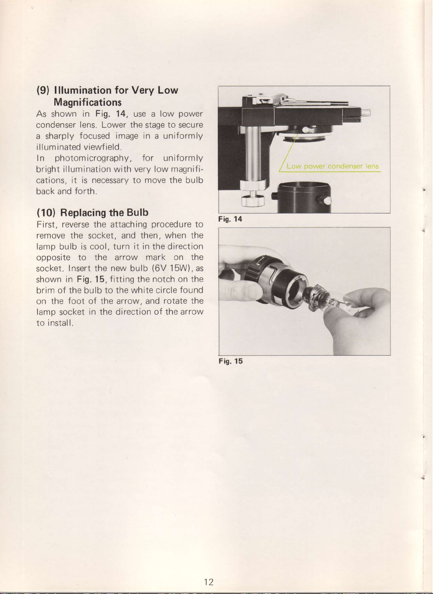
(9)
lllumination for Very Low
Magnifications
As shown
condenser
a sharply
il I
um
In
bright illumination
cations,
back and
(10)
First,
remove the socket, and
lamp bulb
opposite
socket.
shown
brim
on the
lamp
to instal
in Fig.
lens. Lower
focused
inated viewf ield.
photomicrography,
it is necessary to move the bulb
forth.
Replacing the
reverse
of
socket
the attaching
is cool, turn it in the direction
to the arrow
Insert the
in Fig. 15,
the bulb
foot of the arrow, and
in the direction
|.
use a low
14,
the stage
image in a uniformly
wlth very low magnifi-
Bulb
new
bulb
fitting
to the white circle
power
to
secure
for
unlformly
procedure
then, when the
mark on the
(6V
15W), as
notch on the
the
found
rotate the
of the arrow
to
Fig.
Fis.
14
15
J\
/
Low
power
condenser ens
12
Page 12

(1
Focusing
)
The model
coarse
which
wise
by the
stage and vice versa
(2)
When using
eyepiece tube
ment of the user's eye-sight
discrepancy
eyes
the
piece
After
raising or lowering
turn the adjusting
obtain
well. Then,
distance
the eyepieces left or right
the
both
tageous to memorize
and
future use.
The red dot engraved
lary distance
where the mechanical
comes exactly
eyepoint type) eyepieces
on top,
proper
who wear eyeglasses,
be
tenses.
and
are
rotation
Eyepiece
necessary.
is
adjusting
tube.
focusing
a sharp
knob
eyepieces merge. lt
interpupillary
slipped
Adjustment
provided
is
S-Kt
fine focus
loCated
of either
operator
knobs,
near the
of the focus knobs
lowers the microscope
(Fig.
16, a,
Adjustment
a binocular
for
observation,
between
ring
image
regulate
of
the binocular tube by
(Fig.
17), until the viewfields of
scale indicates the
extension
the
eye-to-lens
on
the right
This is done
on the lefthand eye-
with the right
microscope
the
ring
left or
with
the interpupillary
the attained diopter
distance
on the interpupil-
tube length
160mm. The HK
of
distance.
the eyecup
protect
to
with coaxial,
base.
b).
or
the adjust-
by
your
by
will be advan-
readings for
have
an eyecup
which will
For those
the spectacle
4.
both of
Clock-
trinocular
(diopter)
and left
rotating
eye by
stage,
right
to
left eye
sliding
means
position
be-
(high
give
should
as
of
t0cljstilG
Fig. 16, a
b
Fig. 16,
Fig. 17
Page 13

(3)
Coarse
coarse adjustment
The
tightened
tension
lf the
loose, turn the adjusting
too
clockwise.
adjusted
rotation
be avoided.
Never twist
adjustment
whose
located separately
may
be
microscope
the
between
becomes
the objective
and
eyepiece, lower the stage
specimen
visible.
4X, 10X,40X
parfocal,
when revolved into
another.
knob
Ing.
Focusing
may be
means of the
by
adjusting
rotation of the coarse
by
in the opposite direction
focus
performed
the specimen
less than the
p.221
only is
ring.
'tension
much
Too
turning
as
to be used
,
to be
and are
The use of the
clockwise.
the focus
in traditional
knobs, coarse and
stage
then
and 100X-objectives
required
knobs
(not
coaxial).
follows: First,
as
until the distance
and the
working distance
(See
looking through
examined
approximately
position
for critical
coarse
focus
ring counter-
eased or
focus
knob is
may be
Excessive
should
for
this
microscopes
fine, are
Focusing
raise
objective
of
tableon
p.21
the
the
until
is clearlY
are
focus
in
after
one
focus
fine
focus-
glass
and
(5)
Manipulation of the
18)
a.
b.
c. To
d. To correct
e. To measure
The microscope
revolution of the
lowers the
permits
knob
0.002mm
f
ine
coarse
slide.
Focusing
Fine
necessary:
is
To obtain
To transfer the
edge of the
an
thick specimen.
occur when shifting
under examination.
motion
the
sharpest
viewfield.
focus upon different
a slight
the thickness
is
f ine
microscope stage
reading
direct
looking
scale,
(2ttm\.
is
38mm;
motion.
image.
layers
which
slide.
of an
0.2mm.
on the
the
knob
object
that one
raises or
left-hand
front, to
range
that of
as
fine focus
focus from center
blurring
the
designed
so
focus knob
from
complete
The
the same
(Fig.
to
of
a
may
This
of
I
{
(4)
Preset Device
right-hand
The
lever on its
the
When
clockwise
it
until
cannot
closer to
utilized
stage
for
immersion
locked,
stops,
be turned to move
for
has been
changing
prevents
focus knob has a
(Fig.
drum
lever is
(as
the objective.
quick
oil.
18).
fastened by turning
indicated by
coarse
the
refocusing
lowered
a
specimen
preset
The
damaging the
preset
the arrow)
focus knobs
the stage
preset
This
after
defocused
and
applying
or
device,
objective
is
the
when
I
l
Fis. 18
14
Page 14

(6)
When
cation
space
tive and
attain
For critical
placed
condenser
tween the
Oil
as
objective
men and center
preset
the
nosepiece
After
onto
preset
through
carefully
knob. The
is designed
about
focus
about
from the
the
spoil
when
without
lmmersion
Oil
using the 100X
of immersion
(0.1-0.16mm)
cover
the
the
specified
work immersion
between
immersion
follows:
(dry
lever by
microscope
revolver to
applying
the cover
limit.
the eyepiece
by
1/3
knob, that is, by bringing
0.08mm
parfocal position.
immersion
microscope
the
looking
the
the top
the slide
and
objective
observation
First, using
system),
it in the
turning clockwise.
stage
drop
a
glass,
Then
manipulating
oil immersion
to attain
forward
closer
oil,
into the
eyepiece,
objective,
oil in the minute
between
glass
numerical
and
viewfield. Set
and
the
raise the stage
focus
and
its
rotation
which may sometimes
image
can be
the appli-
the objec-
is necessary
oil
lens of the
well as be-
as
the cover
performed
is
a 10X
focus the speci-
revolve
'100X
of immersion
by
raising the stage
fine
the
100X
critical
of the
to the
bubbles
Air
and are
microscope
removed
to
aperture.
be
should
glass.
or 40X
the
Lower
the
objective.
oil
to the
looking
focus
objective
focus by
fine
the stage
objective
visible
tube
by
in
repeating
piece
or by adding
immersion
Unremoved
impair the image.
finishing the work,
after
remaining oil
cloth
cotton
alcohol
use
objective
Be careful
has
The refractive
should
(7)
Lower the stage
focus
screw.
aged and
been
be 1.515.
Exchanging Stages
knob
The stage
movements
slight
oil or bv
hardened
from the lens
moistened
or immerse the
in xylol.
not to
index of the
by
and
can
of the nose-
a certain
means of a
Therefore,
use immersion
thickened.
means of the
unlock
then be
quantity
needle.
oil may often
immediately
remove
using a soft
with xylol. Never
front
immersion
the
stage
removed.
of
the
of the
oil that
oil
coarse
lock
l
15
Page 15
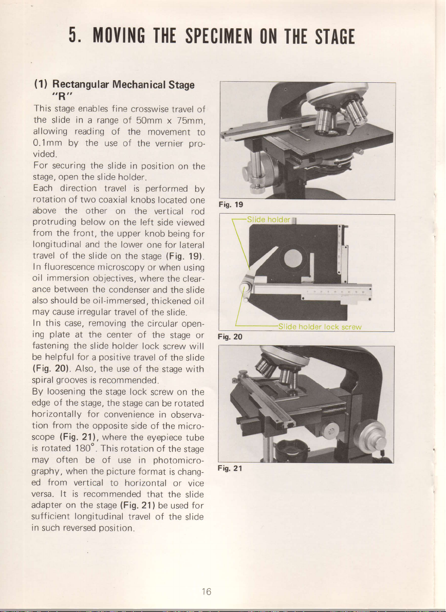
5. |||Ot|ING
(1)
Rectangular
ttRrt
This
stage enables
the
slide in a range
allowing reading
O.imm by the
vided.
For
securing
open
stage,
Each
rotation
above the
protruding
from
longitudinal
travel of
In fluorescence
oil immersion
ance
also
may cause
In this case, removing
plate
ing
fastening
be helpful for
(Fig.
spiral
loosening
By
edge of
horizontally for
tion
scope
is rotated
may often
graphy,
ed from
versa. lt is
adapter on
sufficient
in
such
the
direction
of
two coaxial knobs
below on the
front,
the
the slide on
between the
should be
irregular
at the center
the
20). Also,
grooves
the
stage, the stage
from
the opposite
(Fig.21),
180'. This rotation
when
vertical
the
longitudinal
reversed
Mechanical
f ine
of
of the movement
use of
the
slide
slide holder.
travel
other
on the
the upper
and
the lower
the
microscopy
objectives,
condenser
oil-immersed.
travel of
holder
slide
positive
a
the use of
recommended.
is
the
stage lock
convenience
where
be
of use in
picture
the
to horizontal
recommended
(Fig.21)
stage
travel
position.
THE
SPECIMEN
Stage
crosswise
50mm
the vernier
in
is
left
where
the circular
of the
travel of
side of the micro-
the eyepiece
format
travel of
x 75mm.
position
performed
knob
stage
lock
the
can be
that the
on the
located
vertical rod
side viewed
being
for
one
or when
lateral
(Fig.
the clear-
and the
thickened
the
slide.
open-
stage or
screw will
the
stage
screw on the
rotated
in observa-
of the
photom
is chang-
or vice
be used
of the
to
pro-
by
one
for
19).
using
slide
oil
slide
with
tube
stage
icro-
slide
for
slide
Fig.
19
Fig.2O
Fis.21
T||E
ON
Slide
STAGE
holder
lock
screr"ry
16
Page 16
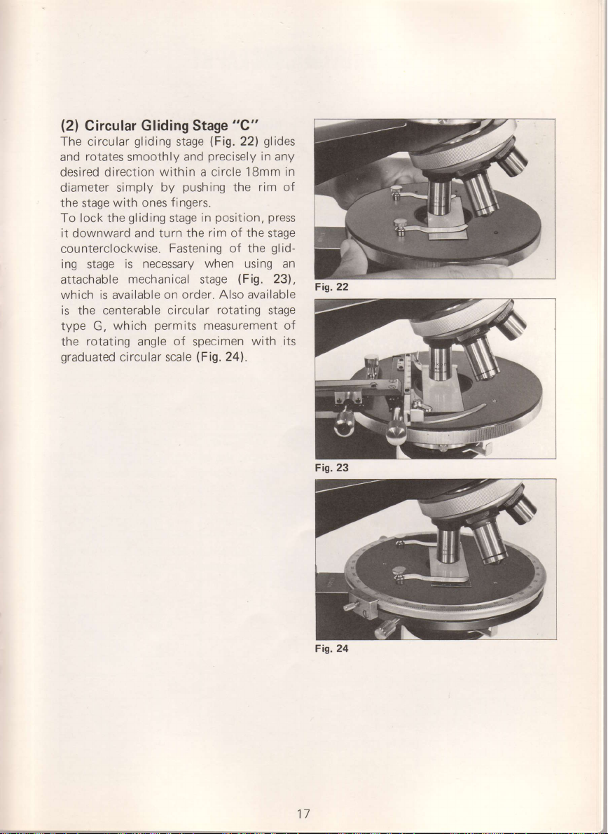
(2)
Circular
circular
The
rotates
and
desired direction
diameter simply
the
stage
To lock the
it downward and turn
counterclockwise.
ing stage
attachable
which is available on
is the centerable
type
G,
rotating
the
graduated
Gliding Stage
gliding
smoothly
within
by
with ones f ingers.
gliding
stage
Fastening
is necessary
mechanical stage
circular
permits
which
angle
circular
scale
"C"
(Fig.
stage
and
pushing
the rim of the
order.
of specimen
(Fig.
22)
precisely
a circle iSmm
the
position. press
in
of the
when using an
(Fig.
available
Also
rotating
measurement of
24).
glides
in any
in
rim
of
stage
glid-
23),
stage
with its
Fis.22
Fig. 23
Fig.24
Page 17
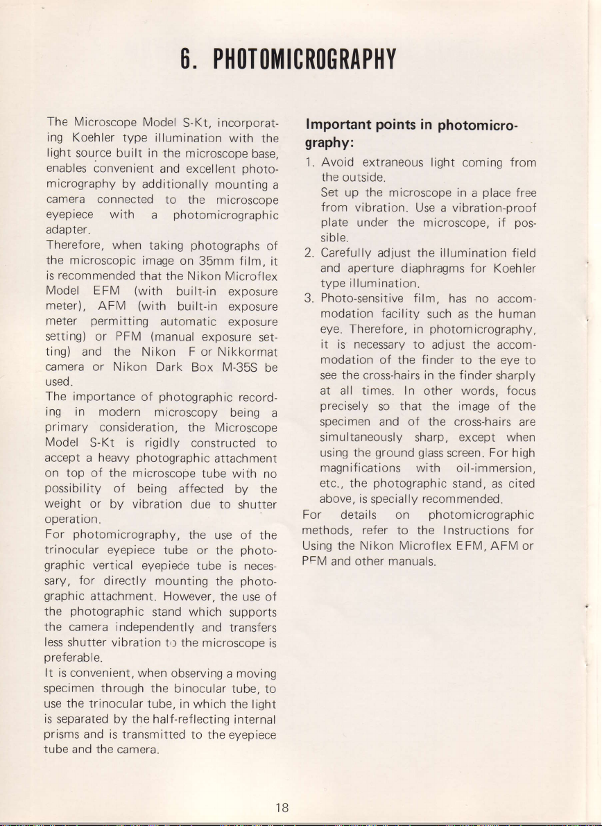
6. P1|OTOillICROGRAP]|Y
The Microscope
ing
Koehler type
light
source built
enables
micrography
camera connected
eyepiece
adapter.
Therefore,
the microscopic
is recommended
Model EFM
meter),
meter
setting)
ting)
camera or
useo.
The importance
ing in
primary
Model
accept a heavy
on top of
possibility
weight
operation.
For
trinocular eyepiece
graphic
sary,
graphic
the
the camera independently
less shutter vibration
preferable.
It is convenient,
specimen
use the
is
prisms
tube and the
convenient
AFM
permitting
or PFM
and
modern m
consideration,
S-Kt
or
photomicrography,
vertical eyepiece
for
attachment. However,
photographic
through
trinocular tube, in
separated by the half-reflecting
and is transmitted
Model
S-Kt, incorporat-
illumination
in the
microscope
and excellent
by additionally
to
the microscope
with
when
the N ikon
Nikon
is rigidly
the microscope
of
by vibration
directly mounting
camera.
photom
a
taking
image on
that the Nikon Microflex
(with
(with
of
photographic
being
when observing
photographs
35mm film,
built-in exposure
built-in exposure
automatic exposure
(manual
Dark Box M-35S
stand which
the
exposure
F or
photographic
icroscopy
the
constructed
tube
affected
due to
the use of the
tube
or the
tube
and transfers
t,t the microscope
binocular tube,
which the light
to
the eyepiece
with
the
base,
photo-
mounting
icrograph
N ikkormat
being
Microscope
attachment
is neces-
the
the use
supports
a moving
a
ic
of
it
set-
be
record-
a
to
with no
by the
shutter
photo-
photo-
of
is
to
internal
lmportant
points
photomicro-
in
graphy:
1. Avoid extraneous light
the outside.
up the microscope
Set
from
vibration.
plate
under
sible.
2. Carefully
and aperture
illumination.
type
Photo-sensitive
3.
modation facility
eye.
Therefore, in
it is necessary
modation
see the cross-hairs in the finder
at all times.
precisely
specimen and of the
simultaneously sharp, except when
using the
magnifications with oil-immersion,
etc.,
above, is
For
methods, refer
Using the Nikon Microflex
PFM
and other
photographic
the
specially
details
Use a vibration-proof
the microscope,
adjust the
diaphragms
film,
to adjust
finder
of the
In other words,
that
so
ground
glass
on
to the Instructions for
manuals.
coming
place
in a
if
illumination
for
Koehler
has no accom-
as the human
such
photomicrography,
the accom-
eve
to the
sharply
image
the
cross-hairs are
screen.
stand, as
recommended.
photomicrographic
EFM,
of the
For high
AFM or
from
free
pos-
field
to
focus
cited
18
Page 18
1.
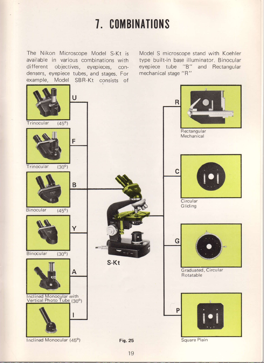
CO]||BINATIO}IS
The Nikon Microscope
available
different objectives,
densers,
example, Model
in various
eyepiece
tubes,
combinations
eyepieces,
SBR-Kt consists
s
Trinocular
s
rinocular
rf
(45")
(30o)
Model
and
stages. For
S-Kt
with
con-
is
of
Model
type
eyepiece
mechanical
microscope
S
built-in base
tube
stage
stand with
illuminator.
"8"
and Bectangular
"R"
m
3
R
Mechan
ectangu
ical
lar
o
lar
Circu
G lid ing
Koehler
Binocular
t
$
Vertical
Photo
with
@(3oo)
Fig.25
19
/-
-.
I
aduated,
R otatable
0
I
.,-._
rti'Fr
Page 19

(1
Interchangeable Eyepiece
)
"U"
a
.
.
.
.
(2)
o
.
.
.
Trinocular
Magnification factor
distance adjustment from
phototube
transmission
vertical tube while viewing
observation binoculars
photo
"F"
Trinocular
Magnification factor
observation binoculars or
graphy.
compensation. Interpupillary distance
"8"
Binocular
Magnif
compensation. Interpupillary distance
"Y"
Magnification factor
provision
to 74mm.
"A"
Magnification factor
photo
lnclined
Magnification
upright,360o rotatable. With
can be
for
tube
Inclined
ication factor
Binocular
for
diopter compensation. Interpupillary distance adjustment
Inclined Monocular with Vertical
tube upright,
Monocular
lnterchangeable
"R"
Rectangular
Stage surface 130mm x
controls which
50mm x 75mm.
"C"
Circular
Stage surface 140mm in diameter.
mechanical
diameter of
desired
"G"
Graduated,
Stage surface
increments
screw. Supplied with stage clips.
"P"
Sguare
Stage surface i30mm x 130mm.
mechanical
Gliding
stage available on order. Moves
18mm in
position.
and
Plain
stage available on order.
1X. Has
switched
photomicrography,
factor
by switching
1.25X. 2-way
from horizontal
30o
1X.
i.25X. Inclined
1X. Observation monocular inclined 30"
360"
1X.
Stages
Medranical
provide
graduated
Scales
straight and/or
Circular
140mm
reads
in diameter. 360o
to
Tubes
provision
54mm to 74mm.
three ways to
through binocular tube; i00% of light directed
total light
Inclined
rotatable,
Inclined
140mm.
exceptionally fine,
Rotatable
6'with
for
diopter compensation and
Observation
built-in
path
light
micro-projection
sliding
directed
and
adjustment
45o and
adjustment
30o
Photo
with built-in, 2 way sliding
45o and
Has low-positioned
to 0.1mm on vernier.
Provided
vernier. Centerable
Provided
prism;
to vertical
rotatable
rotatable
from horizontal and
Tube
rotatable
smooth
with
smoothly
rotating motion.
rotatable.
with
sliding
permit photomicrography
or
from
from
light
total
or closed-circuit
lOOo/o of light directed to
photo
Has
360o.
54mm
Has
360o.
54mm
360o
coaxial X and
cross travel within range of
clips. Accepts attachable
stage
in
any direction
Goniometer
stage
clips. Accepts attachable
stage
20
interpupillary
binoculars inclined 45o,
prism
system,
directed
T.V.
tube for
provision
to 74rnm.
provision
to 74mm.
rotatable
from
prism.
Can be clamped
provided
photomicro-
from
horizontal, and
within circle
divided into 1o
with clamping
light
through
to
to vertical
pickup.
for diopter
for diopter
Has
360o.
54mm
Y motion
in
any
Page 20
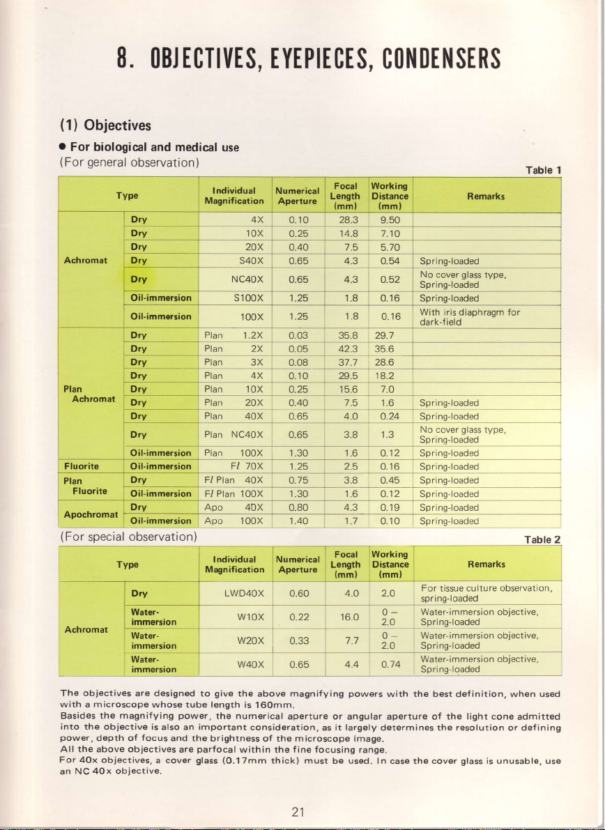
8.
OBJTCTIt|ES,
(1)
Objectives
o
For biological
(For
general
and medical
observation)
Type
Dry
Dw 2OX
Achromat , Dry
,
Dry
Oil-immsrsion
oil.immersion 100x 1 .25
Dry
Dry
Dry Plan
Dry
Plan
Achromat
Dry Ptan
[Orv
-'
!otv_=_
rtrv
Dry
Oif-immersion
Fluorite
Apochromat
(For
special
Achromat
The obiectives are designed
with a microscope
Basides
into the objective is
power,
All the above obiectives
For AOx objectives,
NC
an
Oif-immersion
D:t
Oil-immersion F/ Plan
t ^.:-
ult-rmmersron Apo
observation)
Type
the magniJying
depth of
40x objective.
whose tube length is
focus
power,
also an important
and the
are
a cover
EYEPIECES,
use
I ndividual
Magnif ication
Plan
Plan
Plan
prun
llql 1!l_
ptrn
NC4n)( n Aq ? R
Plan
NC40X
Plan
Fl 7OX
Plul
l{
Apo
Individual
Magnification
LWD4OX
give
to
the numerical
brightness of the microscope image.
parfocal
(O.1
glass
4X
Numerical
Aperture
0.10
Length Distance
28.3
14.8 7.10
S40X
1 .g
l.2X
rox
2OX O.4O
O.O3 35.8 2g.l
2X
0.05
3X
0.08 37.7
4X
0.1 O 2g.5
-l.is
0.65
42.3
15.6 7.o
7.5
4.o
0.65 3.8 1.3
100X 1.30 1.6
aor
_
'100X
40X 0.80
'100X
^,..-^-,^^,
'ifiijjii'
'
WlOX
W2OX
l
W40X
the
above
'l6Omm.
consideration,
within
the
7mm
thick)
1.25
!.75
1.30
1.40 1.7
0.60
o.22
0.33
0.65
magnifying
aperture or angular
fine focusing range.
2.5
9j_0r45_
'l
4.3
'
Focal
t-,""et1'
tmm, tmm,
4.O
16.0
7.7
4.4
it largely
as
must
be used. In case the cover
CONDENSERS
i
9.50
glass
No
cover
Spring-loaded
Spring-loaded
With iris diaphragm for
0.16
dark-field
35.6
28.6
'18.2
1.6 Spring-loaded
0.24_
_
't
O.12
0.16 Sorinq,loaded
.6 O.12 Spring-loaded
0.19 Spring-loaded
0.10 Spring
lworfing
Distanc-e Remarks
2.O
0
2.O Spring-loaded
0
2.O Spring-loaded
^ 1A
powers
determines the
qrr1o-loaded
No cover
?
Sor.s:i"#"j
Spring-loaded
Sprins-loaded
_
I
For
tissue
ng-l
spri
-
Water-immersion objective
-
Water-immersion
Water-immersion objective,
ri nq-l oaded
Sp
with the best
aperture
of the light cone
type
glass
type,
loaded
culture observation,
oaded
objective,
inition,
def
resolution
glass
when
or def ining
is unusable, use
admitted
Table 1
Table
used
2
21
Page 21
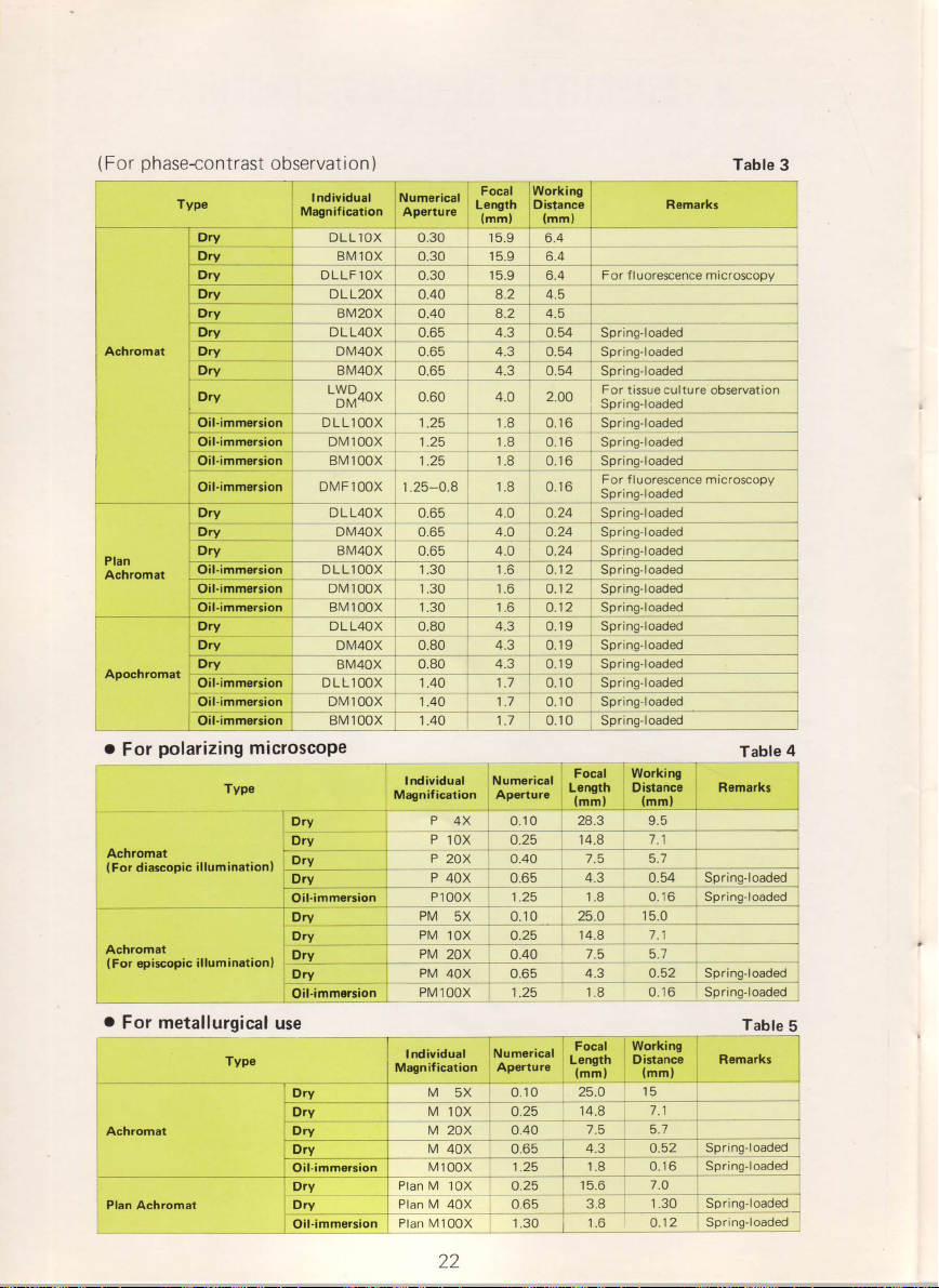
(
phase-contrast
For
Typo
Ach.omat
bw
observat
ory DLLl
Drv
Dry DLLF1oX
Dry DLL2oX
Dry BM20X o.40 4.2
Dry
Dry
Dru
Dry
Oil-immsrsion
OilnnmKis
o
Dry
ion
)
lndividual
Ma0nification
Numsrical
Aperturc
OX 0.30 15.9
Lsngth
eMiox o.30 15.9 6.4
0.30
0.40 8.2
DLL4OX
DM40X
q,,r+ox
L$ff+0"
DLL100X
onr rbox
sv
roox 1 .25
DMF100X
D L L4OX
DIV40X
BM40X
0.65 I 43 i 0.54 Sprins-loaded
0.65 4.3 0.54 Spring-loaded
-0.
0.60
1.25
1 .25
1.25-0.8
0.65
0.65
0.65
Focal
(mm)
15.9
1.8
1.8
1.8 O.16 Sprlng-loaded
1.8
4.0
4.O
4.O
6.4
For f luorescence microscoov
6.4
4.5
For
, ^^
0.16 Spring-loaded
0.16 Spring-loaded
U Ib
o.24 Spri
tissue culture observation
ng-loaded
Spri
For
f luorescence microscopy
sqmclqqgq
ng'loaded
o.24
i
O.24
Sprjng-loaded
Rsmarks
Table
3
Oil-immersion
Apochromat
o
For
Achromat
(For
Achromat
(
For
o
For metallurgical
Achromat
Plan
Oil-immersion
Oil-immersion
Oil-immersion
polarizing microscope
Typ6
illumination)
dia$opic
illuminationl
epi$opic
Type
Achromat
DMlOoX 1:30
BM100X 1.30 1.6
DLL4oX
DM40X 0.80 4.3 0.19
;
0.80 4.3 0.19
BMlooi T -.4L t.z o.to
P
lox 0.25 ^ 14.8
P 20X
P
40x
Oil-immsrsion
D,y
Dry_
Dry
Dry
t,-,-,-
Oil.immsrsion
P10OX 1.25 1.8 0.16 Spring-loaded
PM
5X 0.1 O
PM
IlI _
PM
2OX
PM
""
4OX
r
-:
PM 100X
use
M
5X 0.'1
M
10X
M
20X
M
40X 0.65
M
Oil-immersion
Dry
Oil.immersion
100x 1 .25
Pt".'
v
tox OZs
Plan M
4OX 0.65
Plan M100X
1€ -
0.40
0,65
O.25
,OAO
0.65
l.?9
O.25
0.40
1.30
O.12
9!r'ng-loud"d_
.
Spring-loaded
O.12
Sprlng-loaded
Spring'loaded
-sprins-roaded
7l
7.5 5.7
3.3
_
25.O 1 5.0
14.8
0 25.0
M.A
|
T|
15.6
9.s1
7.1
_
7.5 - 5:7
4.3 0.52 Sprlng-loaded
016
l.q _
15
7.1
7.5 5.1
4.3 O.52
0.16
f
?3
1.30 Sp'i"gf""d"d
3.8
1.6 O.12
4
Table
:elas:!9qgd
_9et!asj!qq"d
ng-loaded
Spri
Spri ng'loaded
Spring'loaded
22
Page 22

(2)
Eyepieces
noiu-iar"r
Type
Huygenian
Wide-fisld
-Iislg9e9,
High
Diopter adiustable high eyepoint,
Filar micrometsr
The
by the
All
High
(3)
Total magnifying
objective
can
extent of object
or the
raising
Shown
"!19ry9$4qq_
€yepoint, compensating
wide-field
compensating,
eyspiece
field
power
eyepieces are
eyepoint
wide-field Bi
model 2
number indicates the
of the
obiective
parfocal
eyepieces
Combinations of Objectives and
power
power
multiplied
made
be
greatest
or
below are the
as to
so
area
thickness of object
lowering
the
T-
!r!<w10x
H KW15X
DH KW10X
effective
gives
used,
within the
enable
easier observation,
obtained
by individual
get
the highest
(real
field) which
microscope
results
compiled
eyep reces:
Obiective Eyepiece
4X
10x5X10x
20x
40x
100x
5X
10x
15X
15X
5X
10x
15X
5X 200x
10x 400x
15X
10x
15X
Total
Magnifying
Power
100x
150X
100x
200x
300x
r 6O0X
1000x
1500x
20x
40x
60x
50x
Working
Distance
(mm)
9.5 2.7
t.t
5.7 0.69- 1 .38
0.54 0.42-0.84
0.16 0.22-O.44 o.22-O.44
Focal
H5X
HlOX
H15X
WF.I
Length
50mm 21
25mm 12.O
16.7mm
OX 25mm 18.0
50mm 21.0 With
31.3mm With
25mm
16.7mm 14.Q With
25mm 18.0
12.5mm 8.0
25mm 14.0
10x
field
visual
the diameter of the
fine focusing range.
o{
especially
Eyepieces
the combination
by
eyepiece
resolution
observed without
can be
(depth
stage, depending
of
from
Resolt
Minimur
I n oblecl
(pml
-5.5
t.t-z-z
focus)
the
Field
Number
.O
8.0
18.6
r e-o
12.O
for
view
a
obiect covered
for
spectacle
power.
of the image
adjustable
adjustable
-l
With
adjustable
adiustable eyepiece collar
With
5X, 10X, 15x
plus
frames
frami no and focus
For
with the
For measurement. Vernier
scale enables direct
M
in imum 0.01mm
particular
is the
A
selection
(resolving
cross-l
measurement
graduation
eyepiece, which, divided
in mm
wearers
product
of the
power),
moving the
can
which
upon the
distinctly seen
be
purpose
of the microscope.
different combinations of
rtron or
r Resolved
I n image
(mm)
0.05-0.1
-O.22
o.1 1
0.16-0.32
0.05-0.1
o.11-O.22 1 .8
7-0.33 1
0.1
o.o7-o.14
o.14-O.24
o.21-O.42
0.08-0.1
7-0.34
0.1
0.25-0.50
0.33-0.66 Q.14
Real Field of Viil
eyepoint
Eyepiece
1 5.25
4.5
3.5
1 2.1
.4
1.06
0.9
o.7
7
o.52
6nF
0.35
0.18
(mml
Huygenian
Eyepiece
Table
Bemarks
eyepiece collar
eyepiece collar
eyepiece col
ines
(real
ar
picrure
for
of 10/100mm
type
reading.
f
ield).
of individual
combination
largest
the
or slide,
stage
without
obiectives and
Table
Depth ot
Focus
(pm)
5.25
364
252
0.8
1.06
0.6
o.4
o.52
0.30
o.20
o.12 0.44
0.08
100
to
10
8
6
4
3
1.8
1.2
i.0
0.38
I
6
7
23
Page 23

The working
and the lowest edge
Table 7,
The resolution
minimum distance
microscope
The
shorter
resolved
oblique
by
p.8)
The
minimum resolved
the total
is important,
the naked eye
generally
microscope
Note that in
resolving
resolution
taken at a lower
field
Real
observation. For
Consequently, it is
under lower
Depth
when
becomes
attention must
By closing the
value
shown
When
because
when
adjust the
distance is the clearance
the working distance
of minimum resolved
illuminated
the
wave length, the higher
distance. In the
and the larger
magnification
choose the eyepiece for
0.15-0.3mm
accepted criterion for
is
about 500-1000X of the numerical
photomicrography
power
focus
of
observed
smaller than the figure
focus
a curvature of
using a
fine
of
of the emulsion
magnification
of view
(in
higher magnif ication it becomes
magnification
represents
through the microscope.
paid
be
condenser
in
the table.
is on
the center of the field,
flat field
focus knob
between the upper surface of the cover
of the objective when
becomes very
between object
by light of wave length
the
table,
values by central illumination.
distance in the image is
microscope.
of the
(when
the upper limit of the total magnification of a
it is
the emulsion
higher
is
and thereafter enlarged.
mm) represents the extent of
advisable to
focusing
to
the image
objective. In order to
center on the object
then revolve the nosepiece to a
and
the thickness or height of the object in
shown in
when taking microscope
diaphragm, the
plane
and shift the
critically focused.
for
small
(the
distance
points
the
smaller values indicate the
lf the resolving
which the image resolution
the object is
useless to
(usually
than that of the
In
depth of field can
the
is unavoidable in the
get
focus from
limit of resolving
discernible
550mpm.
resolving
value in
the
seen
aperture of the
raise
0.05mm).
about
extremely small.
photomicrography
previous
the
circumference will usually be blurred,
sharp
the center
glass
Note
that,
power
high
as separate under the
power,
from
the magnification beyond the
naked eye,
the object that comes under
point
edge images,
that is,
resolution
(see
object multiplied
the
power
a distance of 25cm); the
However,
photographs
to be
higher magnification.
table.
pictures.
made larger than the
be
microscope, except
to the
as shown
objectives.
power)
"lllumination"
of the microscope
falls
within that of
objective
examined
pm
the
depth
Therefore, careful
it
is
periphery.
is the
the smallest
obtained
on
in use.
the
since
can be
first
sharply seen
of focus
necessary to
in
by
24
Page 24

(4)
Condensers
These condensers
illumination of the image field,
microscope image, image contrast
photomicrography,
oblique
an
Abbe
Aplanat 1.40
Achromat 1.25 For critical microscopy
Achromatic-aplanat 1.40
Phase Turret 1.30
L,W.D.
External
Universal
Low-Power o.32
(5)
As shown
transmitted as
illumination device and
Type Numericsl Aporturs Remarks
Turret 0.70
L.W.D, Turret
Dark-Field 1.20-1.40
lllumination System
Fig.26,
in
a
illumination uniform,
collected by
the opening of
illumination
The
lens onto the
Thus, the
for
Koehler
for
the 4X
the illumination
the condenser iris diaphragm.
specimen
illumination system
type illumination
objective as
not only
are
the use of
light emitted from the lamp
the
parallel
provides
field
diaphragm
plane.
well
capable of concentrating the
but also
and depth
an achromat
filter
a
1.30
1.30
0.40
to the mirror. A
bundle
the entire
field
lens onto the
is imaged by the
of the microscope
over a wide
to cover the aperture
as
greatly
of focus. For more critical observation and
or achromatic-aplanat
holder is
For central illumination
(without
For
(with
For
For
With turret-mounted annular diaphragms
contrast microscopV
Working
annular diaphragms
interference microscopy.
Working
diaphragms
For
With
IOX to 100X. ldeallv
objective used
orfunnel
than 1.2mm.
For
Achromats.
specially
oblique illumination
central
and
illumi nation
oblique
increased i | | umi nation
best image
dark-field
outer
low-power
quality
distance
distance
phase{ontrast
for
microscopy.
diameter 36.8mm. To be used with objectives
should
Thickness of slide
stop.
macro-objectives,e.9. 1.2X,2X and 3X
fine
viewfield
front
illumination
model
range
so
as to
angle
light-beam for
influence the
condenserprovided
recommended.
oblique illumination
10
for
30 - 60mm.With
is collected
diffusing
with
focal
slider)
slider)
(f
I uorescence
-
2Omm.
With turret-mounted
phase-contrast
microscopy-
Supplied in
for fluorescence work.
suited
have built-in adjustable
glass
by the collector
filter,
light.
even
plane
of the condenser,
field
fulfills
S-Kt
offer uniform
of the highest
better
resolution of the
with
Table
m icroscopv
for
phase-
and
turret-mounted
centerable mount.
used
)
phase.
annular
100X
iris diaphragm
be less
should
Plan
lens and
make the
serving
to
The light bundle,
covers
lens and condenser
requirements
all the
image
brightness
power
objective.
8
25
Page 25

Fig.
26
Page 26

9. CAt|TIOl{S
I1{ 1|Al{DtIl{G
AND
MAINTENANCE
Avoid touching
dusting,
with a
alcohol
The
be slightly
Tension
of microscope, by
Dismantling
not be attempted,
instrument.
manufacturer.
Do
coarse
dealer
Avoid any
instrument should
hold thet base
transportation,
lenses-objectives,
Protect the
use, it
is available
tighten
microscope substage
microscooe
and
Sufficient
observation
h igher.
The
contrast.
The circuit
electrical interference.
Use the microscope at
short
Also, the
encephalograph
When taking
that there
use a
well-washed soft cotton
or ether
microscope
of the coarse
not
apply
focusing adjustment
or the manufacturer.
should
the locking
eyepieces
Model
wave
the lens surfaces
camel
soft
for
wiping
stand
oiled,
means of the adjusting
internal optical
of the
because it
lt should be
grease
of an
forcible manipulation
be
with one hand and
pack
eyepieces and
microscope
be covered with
on order.
screw
cabinet bottom.
the
at
kept in a container
be
brightness
the
using
L-Ke is
or
S-Ke
microscope is designed
in the
receiver
instrument
is no need
or a noise may be
in a clinical
electro-cardiograms,
for
fingers or
with
hair
off
surfaces should
focus knobs
unspecified
or the
handled carefully
the body
from
When storing
of the
and secure
can not be
binocular
recommended
a distance of
must be
examination
taking
and then
brush
cloth. Wet
finger marks or
be dusted
should
parts
may interfere
only by an
done
gliding
of the
tube,
condenser-in a separate
and store
dust
the vinyl
it in the
eyepiece tube.
it. Fasten
lt is
with desiccant.
obtained in
Model
S-Kt
at least 1-2
heard in
kept 2 meters
however, it
precaution.
this
rough material.
any
wipe the
the cloth with
grease.
be adjusted,
ring, not by twisting
the
and
with the
type to the sliding
stage.
moving
for
e.g.
the arm
rectangular
in a dry
cover or
Place
the
recommended
at a
for use with
minimize the
to
the
room.
lens surfaces
xylol, but
in the same
in this
microscope body should
performance
expert
lf
parts.
carrying
kept in the
cabinet, do
holding screws
interference-phase-contrast
magnification
meters away
reception.
or
found by
is
or the original
necessary,
At all
the
the
with
or circular stage
contai
place.
the support
that
interference
more
For
lightly
never
way and
surfaces
contact
microscope,
When
cabinet
not
the objectives
occurence
from a electro-
practical
may
(S-Kt)
type
knobs.
the
of
the
of the
your
times, the
other. For
and
ner.
not in
which
forget to
under the
for the
600x
phase
tests
or
of
of
from an AF
Page 27
Fuji
NIPPON KOGAKU
Bldg.,2-3,3-chome, Marunouchi,
623 Stewart
NIPPON
Freeport
NIKON VERTRIEBS
4000 Dilsseldorf
Kaspar-Fenner-Strasse
KOGAKU
Avenue,
Garden
NIKON
Bldg., Schiphol-Centrum,
Uerdingerstrasse
,
NIKON
K.K.
Chiyoda-ku, Tokyo
(U.S.A.}
City, New York
EUROPE B.V.
8700 Kiisnacht,
6;
The Netherlands
G.m.b.H.
96/102,
AG
100,
INC.
11530, U.S.A.
West
Germany
Switzerland
Japan
Printed
in
Japan
(74.2,8)
M-6
 Loading...