

NIKON LTZ70WS Repair manual

FCA53001-R.3572.A
作成承認印
配布許可印
FCA53001
REPAIR MANUAL
FCA53201
(With remote control)
FCA53211
Recycled paper
Printed in Japan May 2002
NIKON CORPORATION
Tokyo, Japan
Copyright
All Rights Reserved.
©
2002 by Nikon Corporation.

SPECIFICATIONS
Type of camera 35mm autofocus lens-shutter camera with Nikon zoom lens
Usable lm DX-coded 35mm lm in lm cartridge
Picture format 24 x 36 mm
Lens 28 mm f/5.6–70 mm f/10, 5 elements in 5 groups
Shutter Programmed electronic type, shutter speeds: 2 to 1/300 sec.
FCA53001-R.3572.A
Viewnder
Viewnder information Image size frame marks (with parallax compensation marks); Autofocus frame
Orange LED indications
Green LED indications Ready to shoot (Lights up), Flash being charged (Blinks), Popped-up
Focusing
Focus lock Focus is locked as long as the shutter Release button lightly pressed.
Exposure control
Film speed setting
Film loading
Frame counter Shown in the LCD panel; Additive type; Counts back during lm rewind
Self-timer
Film advance
Built-in ash
Red-eye Reduction mode Red-eye Reduction lamp lights up for approx. 1 second when ash res
Real-image viewnder; frame coverage: approx. over 75% inregular-size frame; approx. 0.33x
magnication at 28mm, approx.0.62x at 70mm; Diopter: approx. –0.1m -
Ready to shoot (Lights up), Flash being charged (Blinks), Popped-up ash unit is being ressed down
(Blinks at 8 Hz)
Activated by lightly pressing the Shutter Release button.
Distance range from approx. 0.8 m (3.0 ft.) to innity
Electronically controlled program AE: auto exposure range (ISO100):EV4 to 16 at 28mm, EV5.5 to
16 at 70mm; Flash res automatically if the available light is low
Valid for DX-coded ISO100, and 400 lms. (ISO100 is automatically selected for DX-coded ISO200
lms. ISO 400 is automatically selected for DX-coded ISO 800 lms.)
Film automatically advances to the rst frame upon completion of lm loading; With a lm cartridge
conrmation window
Electronically controlled; Activated by depressing the Shutter Release button; Self-timer lamp blinks
and lights up (10 seconds in total) to show when ready; Timer duration 10 seconds; Cancelable
Film automatically advances after each shot; Auto rewind at the end of lm roll; Mid-roll rewind
function available
Four ash modes available: Auto Flash, Flash Cancel, Anytime Flash, and Night Portrait (Slow Sync
Flash); Flash automatically res when there is not enough light; Shutter button is locked while the
ash is being charged, Flash shooting range (ISO100): approx. 0.8 to 3.3 m (2.6 to 10.8 ft.) at 28mm,
approx. 0.8 to 1.9 m (2.6 to 6.2 ft.) at 70mm,(ISO400): approx. 0.8 to 6.6 m (2.6 to 21.7 ft.) at 28mm,
approx. 0.8 to 3.8 m (2.6 to 12.5 ft.) at 70mm; Recycling time approx. 7 sec.
1
Battery life Approx. 12 rolls of 24-exposure lm when ash is used for half the exposures
LCD panel (Power is on) Frame counter, Flash mode, Red-eye Reduction, Self-timer, Innity Focus mode, Low battery power
Power source One 3V lithium battery (CR123A type or DL123A)
Date imprint functi on (Lit e
Touch Zoom 70Ws QD only)
Dimensions (W x H x D)
Weight (without battery)
24-hour cycle with no AM/PM; Five indication formats selectable by a push button;
Year/Month/Day, Day/Hour/Minute, no printing, Month/Day/Year, Day/Month/Year;
Leap year adjustment until 2049; Incremental correction of date;
Lite Touch Zoom 70Ws Approx. 113.5 x 64 x 43 mm (4.5 x 2.5 x 1.7 in)
Lite Touch Zoom 70Ws QD Approx. 113.5 x 64 x 47.5 mm (4.5 x 2.5 x 1.9 in)
Lite Touch Zoom 70Ws Approx. 210 g (7.4 oz.)
Lite Touch Zoom 70Ws QD Approx. 215 g (7.6 oz.)
• Specications apply when a fresh battery is used at normal temperature (20°C or 68°F).
- M1・Lite Touch Zoom 70Ws -

DISASSEMBLING
FCA53001-R.3572.A
Rear cover unit
Front cover unit
Discharge of main condenser
Slidecover/Button
Battery cover/Camera back
QD camera back
Flash P.C.B.
Flash unit
AF P.C.B.
Finder unit
Bottom cover/Advance gear/Advance motor unit
Spool
D1
D1
D2
D2
D3
D3
D4
D4
D5
D6
D6
D7
Zoom gear unit
Removing lens barrel unit
Other parts of rear body
Front lens unit
Connected lever
Liner tube
Rear lens unit
Inner helicoid/Outer helicoid
Shutter unit
Other parts of lens barrel base
D7
D8
D8
D9
D9
D10
D11
D11
D12
D12
- Lite Touch Zoom 70Ws -
DISASSEMBLING
Notes: ① Before disassembly, remove the batteries.
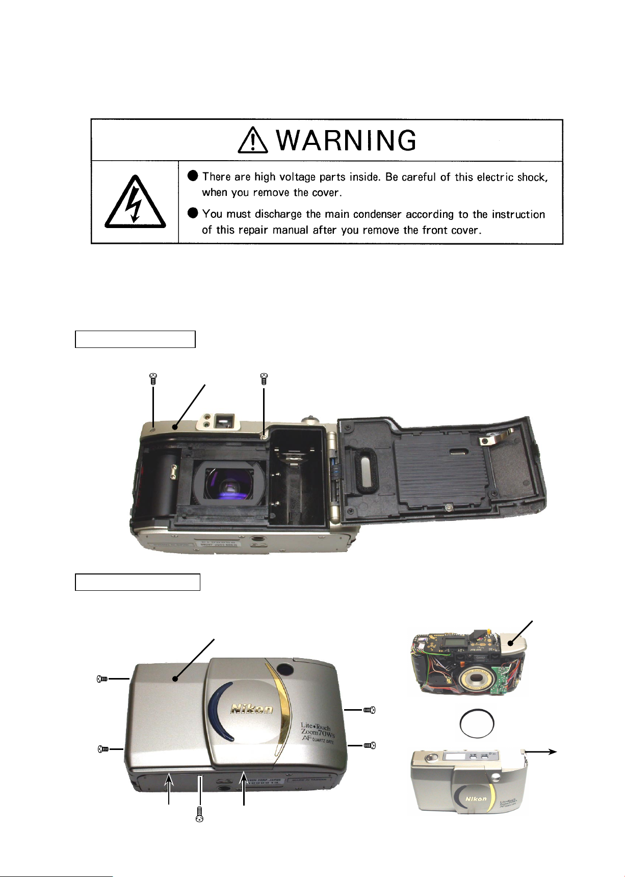
REAR COVER UNIT
Before disassembly, memorize the cord processing condition, the screw installation condition, their kinds, etc.
②
Electric parts are easily affected by static electricity. Be sure to ground them.
③
When removing a gear, take a measure to distinguish its front and rear.
④
FCA53001-R.3572.A
①×2
Rear cover unit
FRONT COVER UNIT
• The front cover hits the ash unit. Bend the end of the cover to the "A" side and remove it.
Front cover unit
Flash unit
①×2
Hook
Hook
③
- D1・Lite Touch Zoom 70Ws -
②×2
⑤
A
③
④

DISCHARGE OF MAIN CONDENSER
FCA53001-R.3572.A
2K Ω /5W
Main condenser
SLIDECOVER/BUTTON
• Insert a knife, etc. into the section "A". Move the slide cover in the arrow mark direction and remove it.
Slidecover
A
- D2・Lite Touch Zoom 70Ws -
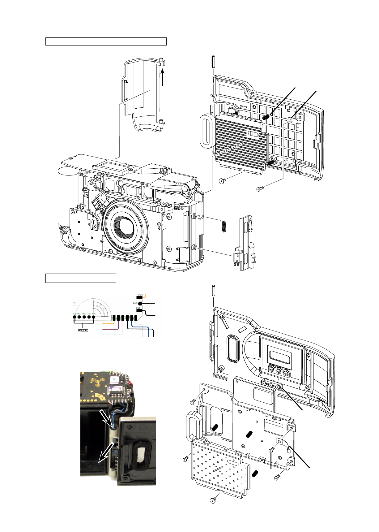
BATTERY COVER/CAMERA BACK
• Bend the battery cover in the arrow mark direction and remove it.
FCA53001-R.3572.A
①
⑪
②
④
⑥
⑦
③
⑨
⑤
⑧×4
⑩
QD CAMERA BACK
Remove the solder of cords as shown belo
①
Pass the cords in the arrow mark direction.
②
Glay
Blue
Black
⑭
w.
Push the pin to remove the camera back.
③
④
⑩
⑨
⑪
⑥
⑤
- D3・Lite Touch Zoom 70Ws -
⑦×4
⑫
⑬
⑧×4
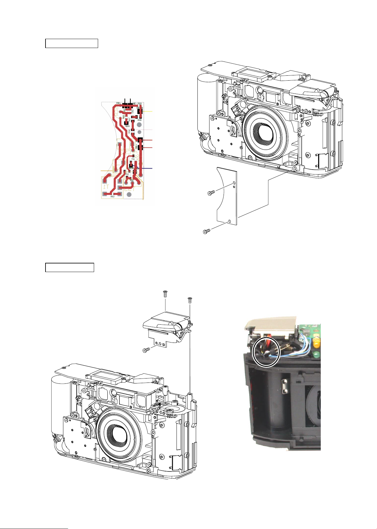
FLASH P.C.B.
Remove the solder of cord as shown below.
①
Black
FCA53001-R.3572.A
Black
Yellow
White
Red
Red
Orange (Rear side)
FLASH UNIT
Orange
③
Blue
①
②×2
②×2
③
Remove the solder of the black and blue cords
④
.
- D4・Lite Touch Zoom 70Ws -
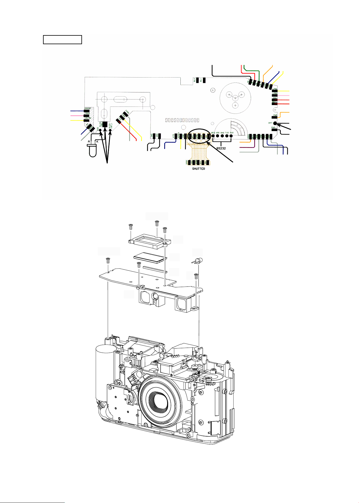
AF P.C.B.
• Remove the solder of the cords and soldering bridges as shown below.
Yellow
Gray
Gray
Red
Black
Blue
Yellow
Black
Black
Red
Orange
Purple
Gray
Green
FCA53001-R.3572.A
Orange
Blue
Yellow
Yellow
White
Red
Red
Orange
Black
Soldering bridges
Black
Soldering bridges
⑥×2
⑧
②×3
④
⑤
Soldering bridges
③
①
⑦
- D5・Lite Touch Zoom 70Ws -
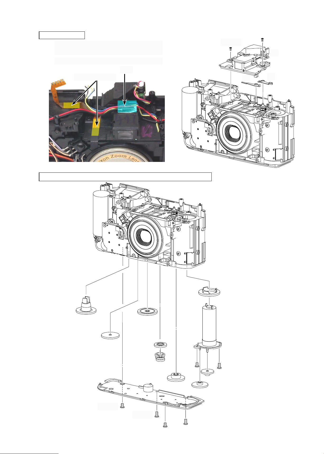
FINDER UNIT
Take off the shutter FPC which is adhered with
①
the double adhesive tape.
Take off the tape and oat the cords.
②
Tape
Double adhesive tape
BOTTOM COVER/ADVANCE GEAR/ADVANCE MOTOR UNIT
③×2
FCA53001-R.3572.A
④
⑥
⑤
③
④
①×2
⑤
⑦
⑥
⑫
⑨
⑧
②×2
- D6・Lite Touch Zoom 70Ws -
⑭
⑬
⑪
⑩
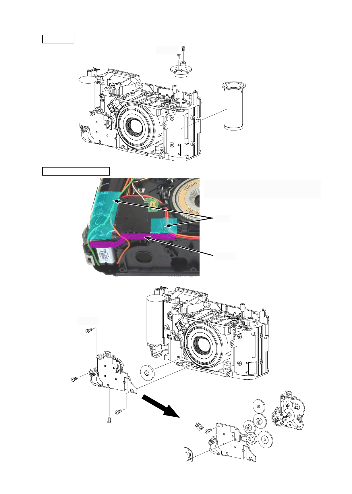
SPOOL
ZOOM GEAR UNIT
①×2
②
FCA53001-R.3572.A
③
After taking off the tape and oating the cords,
①
take off the sponge.
③×3
Tape
Sponge
④
⑤
②
⑦
⑧
⑥
⑨
- D7・Lite Touch Zoom 70Ws -
⑪
⑫
⑭
⑩
⑬

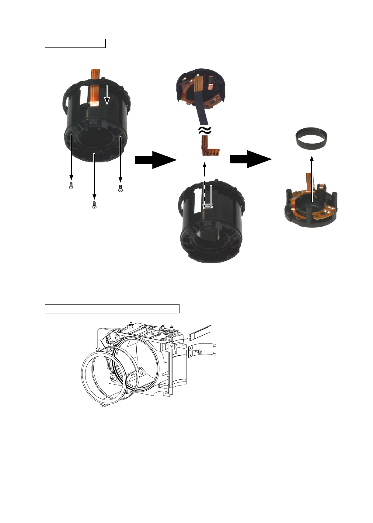
REMOVING LENS BARREL UNIT
④
①
③
FCA53001-R.3572.A
②×3
OTHER PARTS OF REAR BODY
- D8・Lite Touch Zoom 70Ws -
FCA53001-R.3572.A
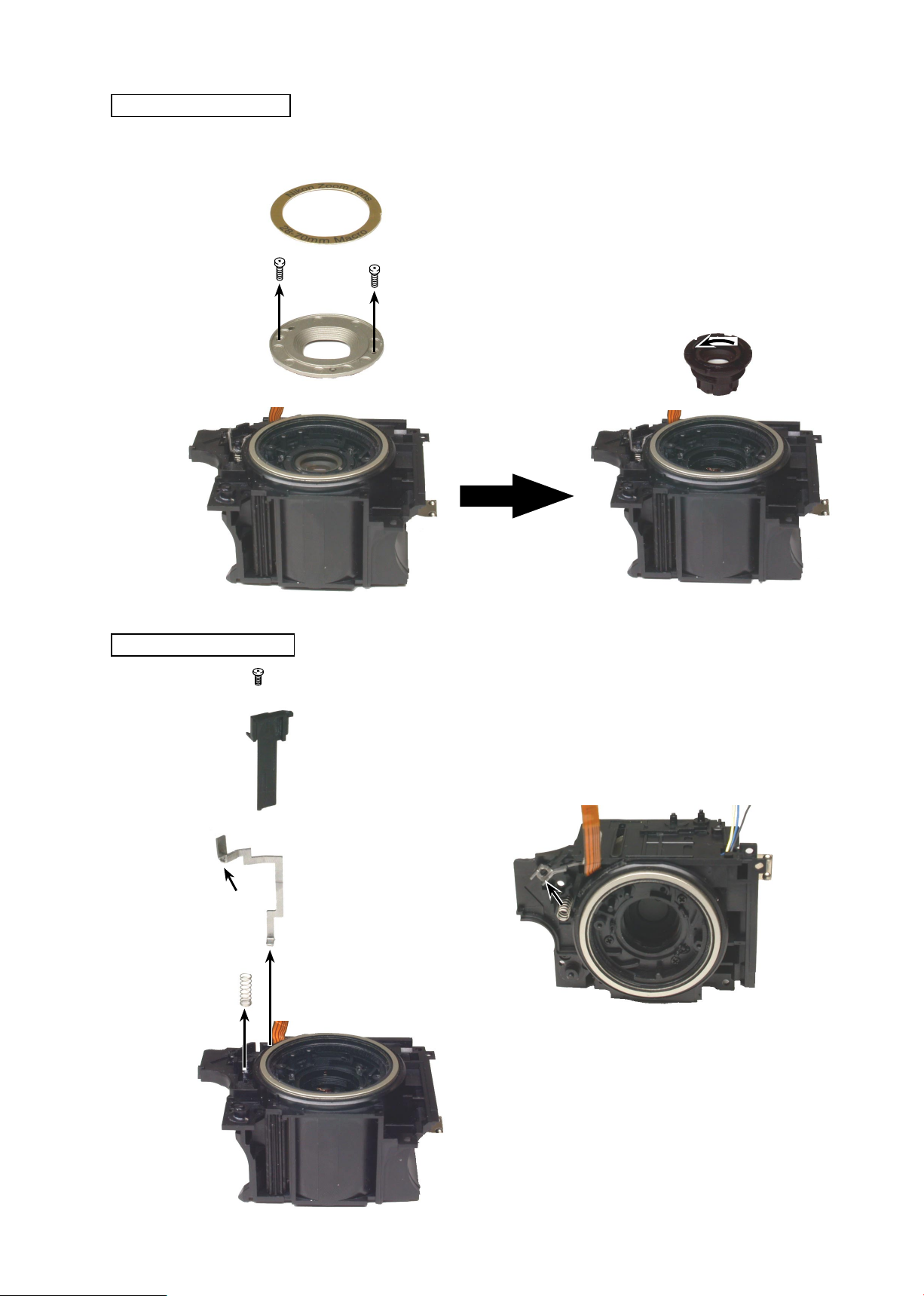
FRONT LENS UNIT
Notes:
The front lens group and the rear lens group are supplied in a set.
When replacing the lens, be sure to replace both lens groups because their optical axes are adjusted together.
①
②×2
③
④
CONNECTED LEVER
④
①
③
②
Remove the connected lever at the arrow mark position.
③
- D9・Lite Touch Zoom 70Ws -
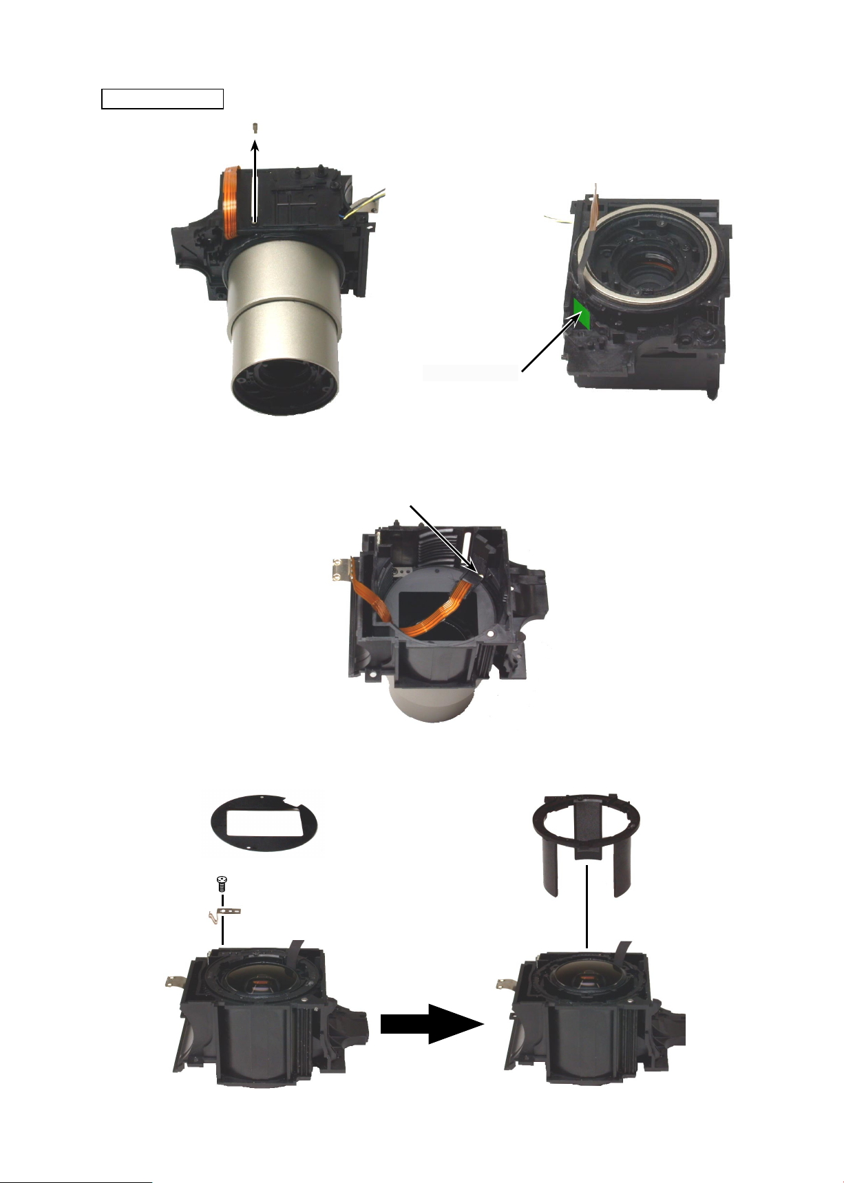
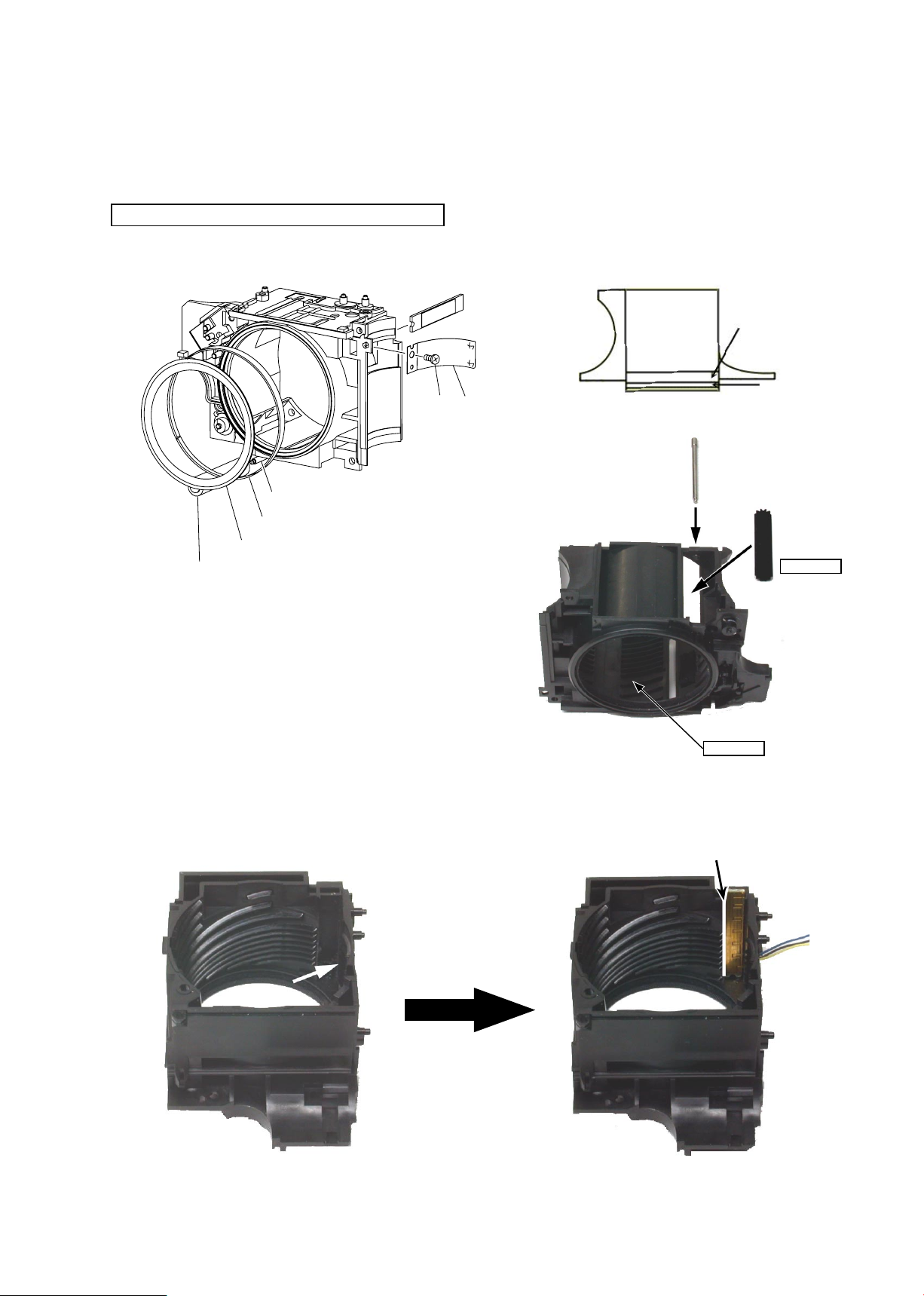
LINER TUBE
①
Light-shield tape
Take off the light-shield tape.
②
FCA53001-R.3572.A
Set to the TELE side and remove the shutter FPC from the hole of "A".
③
A
Take off the light-shield sheet which is adhered with the double adhesive tape.
④
⑦
⑤
⑥
- D10・Lite Touch Zoom 70Ws -

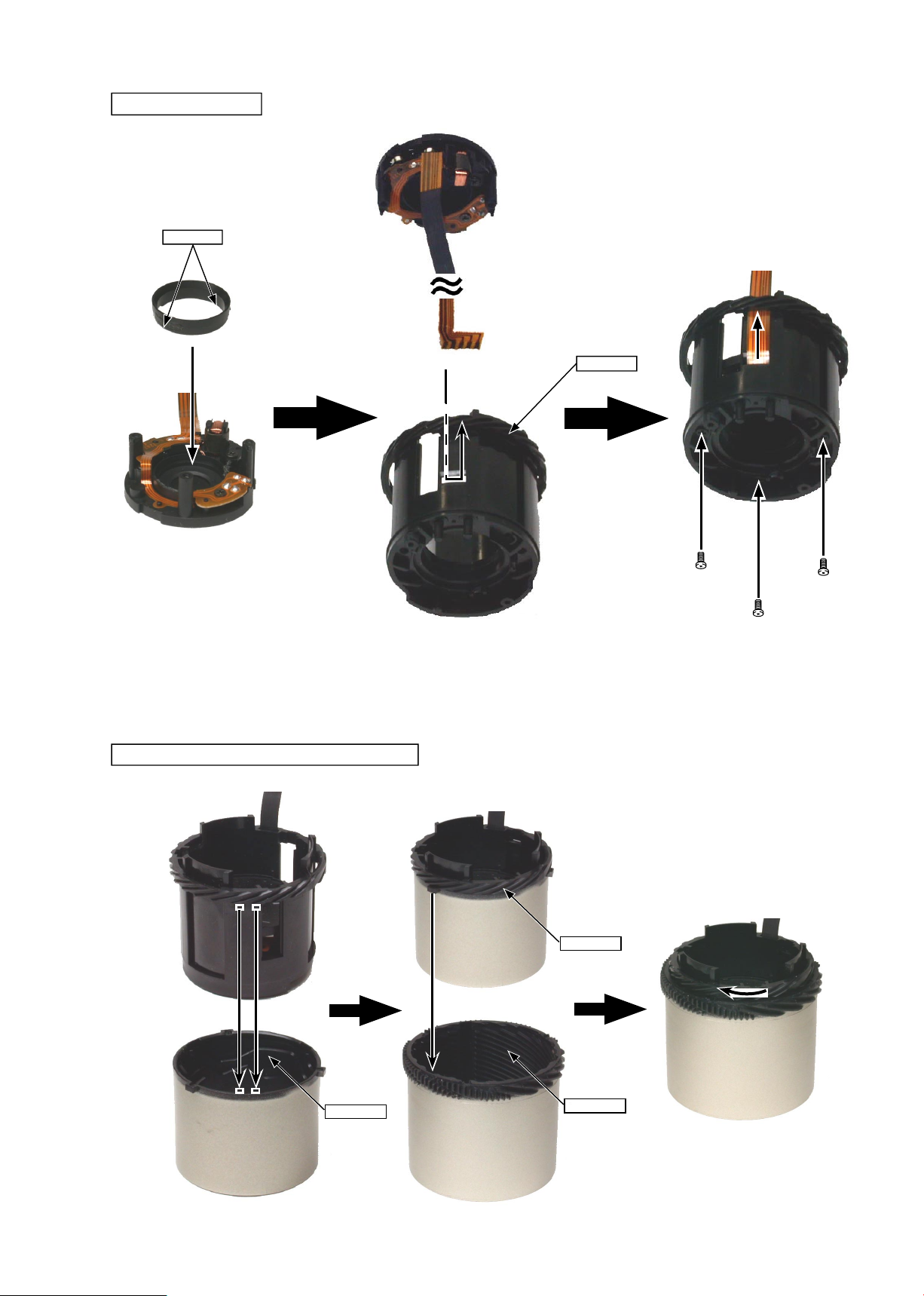
REAR LENS UNIT
FCA53001-R.3572.A
Notes:
When replacing the lens, be sure to replace both lens groups because their optical axes are adjusted together.
The front lens group and the rear lens group are supplied in a set.
•
Turn the inner helicoid to the limit in the arrow mark direction and remove
the rear lens group.
①
②
INNER HELICOID/OUTER HELICOID
①
②
③
- D11・Lite Touch Zoom 70Ws -
SHUTTER UNIT
Remove the shutter FPC in the arrow mark direction.
①
FCA53001-R.3572.A
③
④
②×3
OTHER PARTS OF LENS BARREL BASE
- D12・Lite Touch Zoom 70Ws -

ASSEMBLING / ADJUSTMENT
FCA53001-R.3572.A
Other parts of lens barrel base
Shutter unit
Outer helicoid/Inner helicoid
Attaching helicoid unit to lens barrel base
Rear lens unit
Liner tube
Connected lever
Front lens unit
Other parts of rear body
Attaching lens barrel unit
Zoom gear unit
Spool
Advance motor unit/Advance gear/Bottom cover
Finder unit
A1
A2
A2
A3
A3
A4
A5
A5
A6
A6
A7
A7
A8
A8
AF P.C.B.
Flash unit
Flash P.C.B.
QD camera back
Camera back/Battery cover
Arrange wires
Button/Slidecover
Front cover unit
Check and inspection on camera operation
Prior to inspection and adjustment
Inspection and adjustment of back focus
AF inspection and adjustment
AE inspection and adjustment
BC inspection and adjustment
A9
A10
A10
A11
A11
A12
A13
A13
A14
A14
A20
A25
A28
A31
PI inspection and adjustment
Rear cover unit
Inspection and adjustment when parts are replaced
- Lite Touch Zoom 70Ws -
A31
A33
A33
ASSEMBLING / ADJUSTMENT
1. ASSEMBLING
OTHER PARTS OF LENS BARREL BASE
④
①
②
③
FCA53001-R.3572.A
Light-shield sheet and paper adhering position
①
②
⑦⑤⑥
④
③
MZ-800S
Pass the cord of the zoom PCB through the hole shown by
・
the arrow mark.
MZ-800S
• Fit the end face of the zoom PCB to "A".
A
- A1・Lite Touch Zoom 70Ws -
SHUTTER UNIT
C-8008B
①
FCA53001-R.3572.A
Pass the shutter FPC in the arrow mark direction.
②
MZ-800S
OUTER HELICOID/INNER HELICOID
③×3
MZ-800S
MZ-800S
- A2・Lite Touch Zoom 70Ws -
MZ-800S
 Loading...