

Page 1
NÊkon
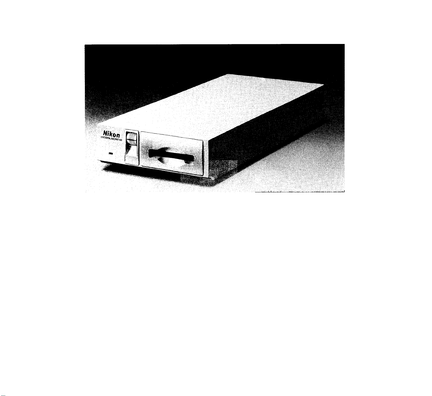
35mm Film Scanner
IIICOOLSCnnill
(LS-IOE Standard model & LS-10 Internal-mount model)
Instruction manual
Before operating the unit, please read this manual throughly
and retain it for future reference.
Mode d’emploi
Avant la mise en service de cet appareil, prière de lire attentivement
ce mode d’emploi et de le conserver pour toute référence future.
Bedienungsanleitung
Lesen Sie vor der Inbetriebnahme diese Anleitung sorgfältig durch
und bewahren Sie sie zum späteren Nachschlagen gut auf.
Page 2

Table of Content
Chapter 1 Getting Started
1-1 Unpacking .................................................................. 4
1-2 Checking the Parts List .............................................. 4
1-3 Components of Internai-mount Modei (LS-10) .... 4
1-4 Components of Standard Model (LS-10E)
1-5 Software Backups ...................................................... 6
1-6 Minimum System
1- 7 Notes on Use ...................................................... 8
Chapter 2 Setting the Standard Modei (LS-10E)
2- 1 Setting Up the LS-10E Scanner
2-2 Setting the SCSI ID .................................................. 16
2-3 Terminating the SCSI Chain .................................... 20
2-4 Connecting to the Computer SCSI
2-5 Setting Up the SCSI Chain
2- 6 Setting Up a SCSI Chain with the LS-10E
Chapter 3 Setting Up the internai-mount Model
3- 1 Setting Up the LS-10 Scanner .......................... 28
3-2 Installing the LS-10 Scanner
3-3 Setting the SCSI ID
3-4 Terminating the SCSI Chain
3-5 SCSI Cables Used with Internal Scanners
3-6 Connecting to the Computer SCSI
3- 7 Setting Up a SCSI Chain with the LS-10 ................. 50
Chapter 4 Using the Scanner
4- 1 Knowledge of Films ................................................. 52
4-2 Operation to Use a Slide Film
4-3 Operation to Use a Strip Film Holder
4-4 Focus ....................................................................... 70
4-5 Calibration ............................................................... 74
4-6 LED Indicator
4-7 TERM. PWR Switch ................................................ 76
Specifications ..................................................................... 78
.......................................................
......................................
(LS-10)
...................................
.................................................
...................................
.................................
..........................................................
................
.......................
..........................
.......
.............
..........................
.............
14
22
24
26
30
40
46
46
48
54
62
76
6
6
Page 3

Sommaire
Inhaltsverzeichnis
Chapitre 1 Mise en route
1-1 Déballage
1-2 Vérification du contenu .............................................. 5
1-3 Pièces du modèle interne (LS-10) ............................. 5
1-4 Pièces du modèle standard (LS-10E)
1-5 Copies de sauvegarde du logiciel
1-6 Configuration minimum
1- 7 Notes d'utilisation
Chapitre 2 Raccordement du modèie standard
2- 1 Préparation du scanner LS-10E .............................. 15
2-2 Sélection d’ID SCSI ................................................. 17
2-3 Terminaison de la chaîne SCSI
2-4 Connexion SCSI à l’unité centrale
2-5 Établissement de la chaîne SCSI ............................ 25
2- 6 Intégration du LS-10E à la chaîne SCSI
Chapitre 3 Montage du modèle interne (LS-10)
3- 1 Préparation du scanner LS-10
3-2 Installation du scanner LS-10
3-3 Sélection d’ID SCSI
3-4 Terminaison de la chaîne SCSI ............................... 47
3-5 Câbles SCSI utilisés avec des scanners
internes ................................................................... 47
3-6 Raccordement au port SCSI de l’unité
centrale .................................................................. 49
3- 7 Intégration du LS-10 à la chaîne SCSI
Chapitre 4 Utilisation du scanner
4- 1 Connaissance des films
4-2 Numérisation de diapositives
4-3 Numérisation de film en bande
4-4 Mise au point ........................................................... 71
4-5 Calibrage ................................................................. 75
4-6 Diode-témoin ........................................................... 77
4-7 Interrupteur TERM. PWR
Caractéristiques
..................................................................
.......................
.............................
.............................................
......................................................
(LS-10E)
..............................
..........................
.................
................................
.................................
................................................
............
...................................
..................................
...............................
........................................
...............................................................
21
23
27
29
31
41
51
53
55
63
77
79
Kapitel 1 Vorbereitungen
5
7
7
7
9
1-1 Auspacken ................................................................ 5
1-2 Prüfen der Teileliste .................................................. 5
1-3 Teile des Einbaumodells (LS-10)
1-4 Teile des Standard-Modells (LS-10E)
1-5 Sicherungskopien der Software ................................ 7
1-6 Geräte-Mindestanforderungen
1- 7 Allgemeine Hinweise
Kapitel 2 Anschluß des Standard-Modells (LS-10E)
2- 1 Aufstellen des externen Scanners LS-10E
2-2 Einstellen der SCSI-Adresse
2-3 Abschluß der SCSI-Kette
2-4 Anschluß an die SCSI-Schnittstelle
des Computers
2-5 Aufbau der SCSI-Kette
2- 6 Aufbau einer SCSI-Kette mit dem LS-10E
Kapitel 3 Anschluß des Einbaumodells (LS-10)
3- 1 Montage des Scanners LS-10
3-2 Einbau des Scanners LS-10
3-3 Einstellen der SCSI-Adresse .................................. 41
3-4 Abschließen der SCSI-Kette ................................... 47
3-5 SCSI-Kabel des Einbau-Scanners
3-6 Anschluß an die SCSI-Schnittstelle des
Computers ............................................................. 49
3- 7 Aufbau einer SCSI-Kette mit dem LS-10
Kapitel 4 Bedienung des Scanners
4- 1 Grundsätzliches zum Film
4-2 Verwendung von Umkehrfilm .................................. 55
4-3 Verwendung des Fllmstreifenhalters
4-4 Scharfeinstellung .................................................... 71
4-5 Kalibrierung ............................................................. 75
4-6 LED-Anzeige ........................................................... 77
4-7 Abschlußstromschaiter (TERM. PWR)
Technische Daten
......................................................
...........................................
............................................................
.............................
......................
.................................
.........................................
......
..................................
.......................................
......
.........................
..................................
.........................
........
...............................
......................
...................
15
17
21
23
25
27
29
31
47
51
53
63
77
79
5
7
7
9
Page 4

Getting Started
1-1 Unpacking
Care should be exercised when unpacking the scanner.
Foilow the instructions beiow before beginning the
installation procedure.
1. Remove ail packaging materials from the scanner
and the Interface kit.
2. Check for damage whiie unpacking the scanner. If
you notice any damage, notify the dealer or the
Nikon sales office where you purchased the scanner.
3. Save all shipping and packaging materials in case
you want to ship the scanner in the future.
1-2 Checking the Parts List
Each scanner package, whether internal or external,
includes all of the necessary hardware, software,
documentation and cabling to get you to started
scanning film. Check the components in the LS-10/
LS-10E packaging against the following parts list to
insure that you have unpacked all contents.
1-3 Components of Internai-mount
Modei (LS-10)
The internal scanner package contains the following
items:
1. Scanner LS-10
2. Strip film holder FH-1
3. SCSI 50-pin flat cable IS-1
4. DC power cable IW-1
5. Internal mounting kit IP-1
6. Utility software for MS-Windows
7. User’s manual
Page 5

1
1
Mise en route
1-1 Déballage
Déballez le scanner et ses accessoires avec précaution.
Respectez les consignes suivantes avant de procéder à
l'installation.
1. Enlevez le matériau d'emballage du scanner et des
accessoires.
2. Vérifiez qu'aucun élément n’est endommagé. Si vous
constatez un dommage, signalez-le à votre
revendeur ou à l’agent Nikon chez qui vous avez
acheté le scanner.
3. Conservez l'emballage d’origine, pour le cas où
vous auriez à expédier le scanner ultérieurement.
1-2 Vérification du contenu
L’emballage du scanner interne ou externe contient tout
le matériel, le logiciel, la documentation et le câblage
nécessaires pour la numérisation des films. Pointez le
contenu de l'emballage du LS-10/LS-10E sur la liste des
pièces ci-dessous pour vous assurer qu elles ont toutes
été déballées.
1-3 Pièces du modèle interne
(LS-10)
Vorbereitungen
1-1 Auspacken
Das Auspacken des Scanners sollte mit großer Sorgfalt
erfolgen. Folgen Sie hierzu den nachstehend
beschriebenen Schritten.
1. Entfernen Sie sämtliches Verpackungsmaterial vom
Scanner und der Schnittstelle.
2. Prüfen Sie den Scanner beim Auspacken auf
Beschädigungen. Sollten Sie Schäden feststellen,
setzen Sie sich bitte unverzüglich mit Ihrem Nikon
Händler in Verbindung.
3. Bewahren Sie das Verpackungsmaterial für den Fall
einer zukünftigen Versendung des Geräts auf.
1-2 Prüfen der Teileliste
Jedes Scanner-Modell wird mit sämtlicher zum Betrieb
des Gerätes erforderlichen Hardware, Software,
Dokumentation und Verkabelung geliefert. Vergewissern
Sie sich durch einen Vergleich mit der nachstehenden
Teileliste, daß Sie sämtliche Teile des LS-10 bzw.
LS-10E ausgepackt haben.
1-3 Teile des Einbaumodells
(LS-10)
L’emballage du scanner interne contient les pièces
suivantes:
Scanner LS-10
1.
Porte-film FH-1
2.
Câble en nappe 50 broches SCSI IS-1
3.
Câble d’alimentation lW-1
4.
Nécessaire de montage interne IP-1
5.
Logiciel pour MS-Windows
6.
Mode d’emploi
7.
Die Verpackung des Einbaumodells des Scanners
enthält die folgenden Teile:
Scanner LS-10
1.
Filmstreifenhalter FH-1
2.
SCSI-Kabel (Flachkabel IS-1 mit zwei 50poligen
3.
Steckverbindern)
Gleichspannungskabel IW-1
4.
Einbausatz IP-1
5.
Dienstprogramm für MS-Windows
6.
Benutzerhandbuch
7.
Page 6

1-4 Components of Standard Model
(LS-10E)
The external scanner package contains the following
items:
1. Scanner LS-10E
2. Strip film holder FH-1
3. SCSI cable SS-1D
4. SCSI terminator ST-1
5. AC power cable PW-2
6. Plug-in software for Photoshop
7. Utility software for MS-Windows
8. User’s manual
1-5 Software Backups
As with any software, it is wise to make a complete
backup of the software disk and store the master disk in
a safe place. Always work with the backup copies when
installing the Nikon software.
1-6 Minimum System
As an absolute minimum, an IBM PC-type computer
system must have the following components:
1. 386 or 486 Processor
2. 1 Megabyte of memory
3. Super VGA graphic card
4. Windows 3.0 or later installed
5. SCSI Bus or card slot for the SCSI card included
The recommended computer system should have at
least 4 to 8 megabytes of memory with a 16- to 32-bit
color graphic adapter.
As an absolute minimum, the Macintosh-type computer
system must have the following components:
1. Most of Macintosh models (More than 640 x 480 dots
of monitor resolution is required,), such as
Powerbook, II, Centris and Quadra series.
2. Apple Macintosh system 6,07 or later
3. 32-bit Quick Draw
4. 4 MB RAM (8 MB is recommended)
5. Hard disk (300 MB is recommended)
6. Color display & video card capable of more than
8-bit color reproduction (Full color display & 24-bit
video card are recommended)
7. Adobe Photoshop version 1.07 or later
Page 7

1-4 Pièces du modèle standard
(LS-10E)
1-4 Teile des Standard-Modells
(LS-10E)
L'emballage du scanner standard contient les pièces
suivantes:
Scanner LS-10E
1.
Porte-film FH-1
2.
Câble SCSI SS-1D
3.
Bouchon de terminaison SCSI ST-1
4.
Câble secteur PW-2
5.
Logiciel additionel pour Photoshop
6.
Logiciel pour MS-Windows
7.
Mode d'emploi
8.
1-5 Copies de sauvegarde du
logiciel
Comme pour tout logiciel, il est avisé de faire une copie
de sauvegarde complète de la disquette du logiciel et
de ranger la disquette d’origine dans un endroit sûr.
Travaillez toujours avec les copies lorsque vous
installez le logiciel Nikon.
1-6 Configuration minimum
Pour les ordinateurs de type IBM PC, la configuration
minimum est la suivante:
1. Processeur 386 ou 486
2. 1 Mo de mémoire vive
3. Carte graphique super VGA
4. Windows 3.0 ou ultérieur installé
5. Bus SCSI ou fente pour la carte SCSI Installée
Il est recommandé d'utiliser en pratique une
configuration disposant de 4 à 8 Mo de mémoire vive,
dotée d'une carte graphique couleur de 16 à 32 bits.
Pour les ordinateurs Macintosh, la configuration
minimum est la suivante:
1. La plupart des modèles Macintosh (une résolution
supérieure à 640 x 480 points est requise pour le
moniteur) tels que les séries Powerbook, II, Centris
et Quadra
2. Ordinateur Apple Macintosh au 6.07 ou ultérieur
3. Quick Draw 32 bits
4. 4 Mo de mémoire vive (8 Mo recommandés)
5. Disque dur (300 Mo recommandés)
6. Affichage couleur et carte vidéo capables d’une
reproduction couleur de plus de 8 bits (un affichage
“full color” et une carte vidéo de 24 bits sont
recommandés)
7. Adobe Photoshop version 1.07 ou ultérieure
Die Verpackung des externen Scanner-Modells enthält
die folgenden Teile:
Scanner LS-10E
1.
Filmstreifenhalter FFI-1
2.
SCSI-Kabel SS-1D
3.
SCSI-Abschlußwiderstand ST-1
4.
Netzkabel PW-2
5.
Plug-in-Software für Photoshop
6.
Dienstprogramm für MS-Windows
7.
Benutzerhandbuch
8.
1-
■ 5 Sicherungskopien t
Wie bei jeder Software empfiehlt es sich auch hier,
einen kompletten Satz Sicherungskopien herzustellen
und die Originale an einem sicheren Ort aufzubewahren.
Benutzen Sie zur Installation der Nikon Software
ausschließlich die Sicherungskopien.
1-6 Geräte-Mindestanforderungen
Der IBM-kompatible PC muß folgende
Mindestanforderungen erfüllen:
1. Prozessor 386 oder 486
2. 1 Megabyte Speicher
3. Super-VGA-Grafikkarte
4. Windows 3.0 oder später installiert
5. SCSI-Bus oder Kartenschlitz für die beigefügte SCSIKarte.
Das empfohlene Computersystem sollte mindestens 4
bis 8 MByte Speicher und einen 16- bis 32-BitColorgrafik-Adapter haben.
Der Macintosh-Computer muß folgende
Mindestanforderungen erfüllen:
1. Die meisten Macintosh-Modelle (eine Bildauflösung
des Monitors von mehr als 640 x 480 Punkten ist
erforderlich), wie z.B. die Modelle der Serien
Powerbook, II, Centris und Quadra
2. Apple Macintosh-System ab Version 6.07
3. 32-Bit Quick Draw
4. 4 MB RAM (8 MB ist empfehlenswert)
5. Festplatte (300 MB ist empfehlenswert)
6. Farbdisplay und Grafikkarte, die für eine
Farbwiedergabe von mehr als 8 Bit tauglich sind
(Vollfarben-Display und 24-Bit-Grafikkarte sind
empfehlenswert)
7. Adobe Photoshop ab Version 1.07
Page 8

1-7 Notes on Use Power source
1. Always use the power source of 100 — 240 V,
50 — 60 Hz.
Use the power cord subject to the voltage of power
source, and if you use over AC125 V:
* the plug must be rated for AC250 VISA
(NEMA6P-15).
• the insulation of the cord must be more than SVT
type, and be a suitable cord of at least AWG18 and
approved under safety regulations of the nations in
which it is used.
2. Once the power source is turned off, do not turn it
on until at least 5 minutes have passed.
3. Don’t unplug the unit while the power is on.
4. Don’t hold the cord itself when unplugging the unit.
5. The power source must be grounded. A joint ground
with other instruments is indispensable, or else a
ground loop, which can cause electrical shocks and
electrical noise, may result.
6. Don’t unplug the peripherals while the power is on.
7. Don’t carry the main unit while the power is on.
* Be sure to use the unit in a horizontal orientation only;
a perpendicular orientation will cause misoperation.
* Don’t use a slide mount more than 3 mm thick. If the
slide mount is not flat on its surface, you may feel
some roughness when mounting or unmounting the
slide.
* Don’t force the slide-mount or strip film holder into or
out of the scanner if it does not move smoothly.
* When moving the scanning stage, don’t touch or
unmount the strip film holder.
* Don’t disassemble the main unit. It is dangerous to
touch the internal components because of high-voltage.
* Don’t put the things inside the unit. Flammable
materials, metals, water etc., will cause fire, electrical
shock, damage and misoperation.
In emergency
If you find something unusual, such as abnormal noise,
smells or smoke, turn off the power switch, and take the
unit to the dealer from whom you purchased it.
8
Page 9

1-7 Notes d’utilisation
1-7 Allgemeine Hinweise
Alimentation
1. utilisez toujours un secteur compris entre 100 et 240
volts, 50 à 60 Hz.
Utilisez un cordon secteur approprié à la tension
d’alimentation, et si cette tension est supérieure à
125 V:
* la prise doit être aux normes 250 V 15 A
(NEMA6P-15).
* l'isolation du cordon doit être supérieure au type
SVT, et la section des conducteurs supérieure ou
égale à AWG18, et le cordon d’un type agréé dans le
pays d'utilisation.
Si vous utilisez une tension égale ou inférieure à
125 V:
* la prise doit être aux normes AC125 V 10 A.
2. Si vous coupez l'alimentation du scanner, ne la
rétablissez pas avant cinq minutes.
3. Ne débranchez pas le cordon d’alimentation lorsque
le scanner est sous tension.
4. Ne pas brancher et débrancher la prise en la tenant
par le cordon.
5. Il est nécessaire de relier le scanner à la terre. La
connexion de terre concentrée par tous les appareils
reliés entre eux est indispensable pour un bon
fonctionnement; sinon, cela peut former une boucle
d’induction génératrice de parasites.
6. Ne jamais débrancher un périphérique sous tension.
7. Ne pas déplacer l’unité centrale lorsqu’elle est sous
tension.
* Le scanner doit reposer sur une surface horizontale.
Si on le place verticalement, ceci se traduira par des
anomalies.
* Ne pas utiliser de montures de diapositives
d’épaisseur supérieure à 3 mm. Si la monture de la
diapositive ne repose pas à plat, l’on ressentira
parfois une résistance lors de l’introduction ou du
retrait de la diapositive.
* Si l’on ressent une telle résistance, ne pas forcer pour
introduire ou retirer la diapositive ou le porte-film.
* Ne pas toucher le porte-film pendant la numérisation.
* Ne pas démonter l’unité centrale. La haute tension
présente un danger mortel.
* Ne pas introduire de corps étrangers à l’intérieur de
l’unité centrale. Des objets inflammables, métaux, eau,
etc., peuvent provoquer un incendie, une électrocution,
des dommages et des anomalies.
En cas d’urgence
Si vous trouvez quelque chose d’anormal, bruit, odeur,
fumée, coupez l’alimentation et faites parvenir le
scanner à votre revendeur.
Spannungsquelle
1. Das von Nikon mitgelieferte Netzkabel entspricht den
einschlägigen Bestimmungen über die elektrische
Sicherheit. Wenn Sie ein anderes Netzkabel
verwenden, achten Sie auf das Vorhandensein des
VDE- bzw. TÜV-Prüfzeichens. Die Prüfwerte 250 V
und 15 A dürfen nicht unterschritten werden!
2. Nach dem Ausschalten des Gerätes müssen
mindestens fünf Minuten verstreichen, bevor das
Gerät erneut eingeschaltet wird.
3. Der Netzstecker darf nur bei ausgeschaltetem Gerät
gezogen werden.
4. Fassen Sie das Netzkabel zum Trennen der
Verbindung grundsätzlich nur am Stecker, niemals
direkt am Kabel!
5. Der Netzanschluß muß unbedingt geerdet sein. Die
Erdung ist beim Betrieb mit anderen Geräten
unerläßlich, da sonst eine Erdschleife entsteht, die
zu elektrischen Schlägen und Rauschen führen kann.
6. Die Verbindung zu Peripheriegeräten darf nur bei
ausgeschaltetem Gerät unterbrochen werden.
7. Das Gerät darf nur in ausgeschaltetem Zustand
transportiert werden.
* Das Gerät darf nur in horizontaler Stellung betrieben
werden. Bei vertikaler Aufstellung ist ein fehlerfreier
Betriebsablauf nicht gewährleistet.
* Die maximal zulässige Dicke von Diarähmchen beträgt
3 mm. Falls die Oberfläche des Diarähmchens nicht
flach ist, kann das Einschieben oder Auswerfen des
Dias manchmal nicht ganz reibungslos ablaufen.
* Bei Einlegen oder Entnehmen des Dias oder
Filmstreifenhalters ist jede Gewaltanwendung zu
vermeiden.
* Während des Scannens darf der Filmstreifenhalter
weder berührt noch entnommen werden.
* Jeder Eingriff in das Gerät ist zu unterlassen. Durch
Hochspannung droht Lebensgefahr!
* Das Geräteinnere darf nicht mit Fremdkörpern in
Berührung kommen. Metall, Wasser und brennbare
Materialien können Feuer, elektrische Schläge,
Geräteschäden oder Betriebsstörungen verursachen.
In einem Notfall
Schalten Sie das Gerät im Falle ungewöhnlicher
Geräusch-, Geruchs- oder Rauchentwicklung
unverzüglich ab und verständigen Sie den Nikon
Kundendienst.
Page 10

Safety regulation
Hinweis:
Dieses Gerät entspricht der europäischen
Sicherheitsnorm EN60950, hat die GS-Marke erhalten
und erfüllt die Norm-Vfg 243/1991 Klasse B für unnötige
Sekundarstrahlung. Dieses Gerät sollte nur in
Ausrüstung eingebaut werden, die denselben Normen
(TÜV, f-Marke usw.) entspricht.
For regular use
Avoid using and storing the scanner in locations that
are:
* extremely hot or cold, (from +10 to +35°C)
* near heat sources or in direct sunlight.
* exposed to moisture or dust.
* exposed to hard vibration.
Avoid hard physical shocks to the main unit.
Note on transportation
When transporting the main unit, always use the
packaging materials in which the main unit was packed
when you purchased it. The focus dial must be turned
downward to the end before packing. If you have lost the
packaging materials, use materials designed to protect
precision instruments from vibration and physical
shocks. Be especially careful when using air or courier
service.
Taking this product out of country
The use of this product may violate local laws and
restrictions in some countries. If this is the case, we can
not bear any responsibility for any violations resulting
from the use of this product. Note that, in some
countries, this product can be made to conform with
regulations through an internal adjustment. Therefore,
before taking this product out of the country, consult
with your service representative.
10
Page 11

Réglementations de sécurité Sicherheitsbestimmung
Hinweis;
Dieses Gerät entspricht der europäischen
Sicherheitsnorm EN60950, hat die GS-Marke erhalten
und erfüllt die Norm-Vfg 243/1991 Klasse B für unnötige
Sekundarstrahlung. Dieses Gerät sollte nur in
Ausrüstung eingebaut werden, die denselben Normen
(TÜV, f-Marke usw.) entspricht. '
Hinweis:
Dieses Gerät entspricht der europäischen
Sicherheitsnorm EN60950, hat die GS-Marke erhalten
und erfüllt die Norm-Vfg 243/1991 Klasse B für unnötige
Sekundarstrahlung. Dieses Gerät sollte nur in
Ausrüstung eingebaut werden, die denselben Normen
(TÜV, f-Marke usw.) entspricht.
Conditions d’utilisation normales
Evitez d'utiliser et de stocker le scanner dans les
conditions ci-dessous:
* froid ou chaleur extrêmes (température recommandée
de -t-10 à +35°).
* près d’une source de chaleur, ou sous la lumière
solaire directe.
* dans des endroits excessivement poussiéreux ou
humides
* dans des conditions de fortes vibrations.
Manipulez le scanner avec précautions, et évitez les
chocs.
Remarques sur le transport
Si vous devez expédier le scanner, utilisez les
matériaux d’emballage et le conditionnement avec
lesquels le scanner vous a été livré. La molette de mise
au point doit être positionnée à fond vers le bas avant
l'emballage. Si vous ne disposez plus des matériaux
d’emballage d’origine, procurez vous des matériaux
identiques, qui amortissent les chocs et absorbent les
vibrations. Soignez particulièrement l’emballage pour
les expéditions par Air ou Poste.
Utilisation de ce produit à i’étranger
L’utilisation de ce produit peut contrevenir à la
réglementation et aux restrictions locales de certains
pays. Dans un tel cas, notre responsabilité ne saurait
être engagée pour toute infraction résultant de
l’utilisation de ce produit. Notez, toutefois, que, dans
certains pays, il est possible de rendre ce produit
conforme à la réglementation par un réglage interne.
Avant d’utiliser ce produit à l’étranger, adressez-vous
donc à votre agent de service après-vente.
Im Normalbetrieb
Vermeiden Sie die Benutzung bzw. Aufbewahrung des
Scanners unter den nachfolgend aufgeführten
Bedingungen.
* An sehr heißen oder kalten Orten (außerhalb von -MO
bis -l-35°C).
* In der Nähe von Hitzequeilen oder im direkten
Sonnenlicht.
* Bei sehr hoher Feuchtigkeit oder starkem Staub.
* Bei starken Schwingungen.
Schützen Sie das Gerät vor Schlägen.
T ransporthinweise
Versenden Sie das Gerät ausschließlich in seiner
Originaiverpackung. Die Feinfokussierung muß vor dem
Einpacken ganz nach unten gedreht werden. Sollte die
Originalverpackung nicht mehr zur Verfügung stehen, ist
auf besonders widerstandsfähige Verpackung zu achten,
wie sie für Präzisionsgeräte geeignet ist. Dies gilt
besonders für den Versand auf dem Luftwege oder per
Spediteur.
Benutzung dieses Produktes im
Ausland
Der Betrieb dieses Produktes kann in einigen Ländern
gegen die örtlichen Gesetze und Bestimmungen
verstoßen. Sollte dies der Fall sein, so übernehmen wir
keinerlei Haftung für etwaige Verstöße, die auf den
Betrieb dieses Produktes zurückzuführen sind. Wir
weisen darauf hin, daß für einige Länder eine interne
Einsteilung an diesem Produkt notwendig sein kann, um
es den geltenden Bestimmungen anzupassen. Wenden
Sie sich daher an Ihre Kundendienststelle, bevor Sie
dieses Produkt ins Ausland mitnehmen.
11
Page 12

Note on installation
1. Turn off the power switches for the equipment. (The
LS-10 is not provided with a power switch. Aiways
turn off the switch on the computer.)
2. Turn off the power switches for ali the devices
(printer, display) connected to the computer.
3. Move the key to the unlock position if the computer
has a key-lock mechanism.
4. Unplug all the cables, including the power cords.
Remove the cover of computer as described in the
5.
manual.
Remove the cover of the bay as described in the
6.
manual.
'Warning! ' ‘ ‘
Electrostatic discharge will 'damage the scanner if
you touch the s'canner’s connector pins. Do not
touch the pins.'' ' "
12
Page 13

Remarques sur l’installation
1. Mettez l’interrupteur des périphériques sur Arrêt.
(Le LS-10 ne dispose pas d’un interrupteur: coupez
toujours l’alimentation de l’unité centrale.)
2. Mettez tous les interrupteurs de tous les
périphériques (imprimante, écran) reliés à l’unité
centrale sur Arrêt.
3. Mettez le cas échéant la clé de sécurité de l’unité
centrale sur déverrouillage.
4. Déconnectez tous les câbles reliés à l’unité centrale,
y compris le câble secteur.
5. Déposez le capot de l’unité centraie selon les
instructions de son mode d’emploi.
6. Déposez le capot du logement selon les instructions
du mode d’emploi.
AttentionI ,, ^
Une décharge d’éllsctricité, statique peut gravernênt'i
endommager les circuits du scanner. Ne touchez
jamais les broches du connecteur du scanner.
Installationshinweise
1. Schalten Sie die Hauptschalter der Geräte aus.
(Der LS-10 besitzt keinen eigenen Hauptschalter.
Schalten Sie das Gerät stets mit dem Hauptschalter
des Computers aus.)
2. Schalten Sie auch sämtliche an den Computer
angeschlossenen Peripheriegeräte aus (Drucker,
Monitor usw.).
3. Sofern der Computer mit Schlüssel verriegelt
werden kann, muß er geöffnet werden.
4. Trennen Sie den Computer von der Netzspannung
und entfernen Sie alle von außen eingesteckten
Kabel.
5. Entfernen Sie das Computergehäuse wie im
Computer-Handbuch beschrieben.
6. Entfernen Sie die Abdeckung des Laufwerkschachts
wie im Computer-Handbuch beschrieben.
Achtung!
Vermelden Sie jede Berührung der Sleekerkontaktol
''Eine' dl^ktrostatische'Entladun'g'kann das Gerät ’ ''
beschädigeni
'■ ' i" I ' ^ t».i ' 1 ’ I*. ' - ,m’ I i'« '■*
13
Page 14
[a]
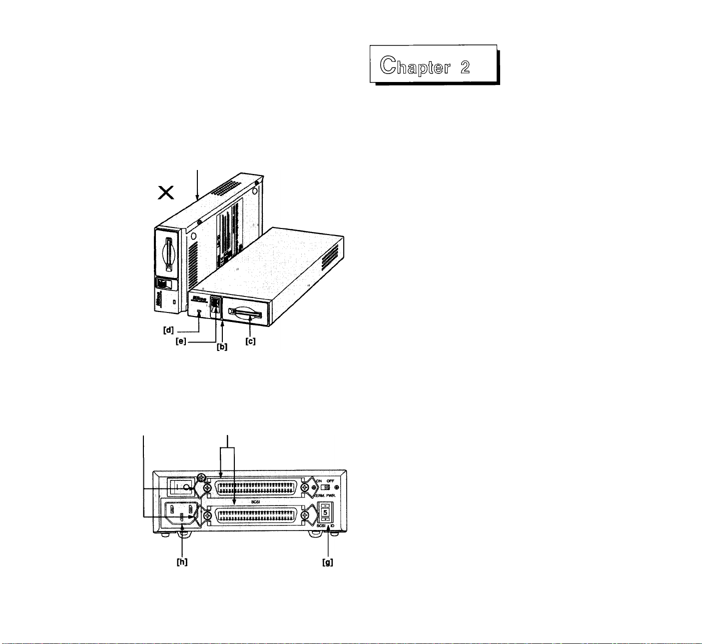
Fig. 2.1 The LS-10E scanner
Le scanner LS-10E
Der Scanner LS-10E
[i]
Fig. 2.2
The LS-10E scanner (Rear view)
Le scanner LS-10E (vue arrière)
Rückseite des Scanners LS-10E
[f]
Setting the Standard Model
(LS-10E)
2-1 Setting Up the LS-10E Scanner
Let’s take a look at the LS-10E scanner as shown in
Figure 2.1. Note that the face of the LS-10E is identical
to the LS-10 scanner. The front of the scanner includes
the film slot, focus control and active light.
[a] Not standable
[b] LS-10E correctly seated
[c] Insert slide here
[d] Active indicator
[e] Focus control
The rear panel of the LS-10E is shown in Figure 2.2.
Note that there are four items of interest on the rear
panel. These are the AC power connector, the two SCSI
connectors, the SCSI ID switch and the SCSI locking
rings.
[I] SCSI connectors
[g] SCSI ID switch
[h] AC power connector
[i] SCSI locking rings
The LS-10E is oriented on its base. When on its base, it
can be positioned next to or on top of the computer. This
provides maximum stability.
Placing the scanner next to the
computer
Although the scanner is very insensitive to
environmental conditions, the following guidelines and
precautions should be followed when finding a home for
the scanner.
Place the scanner near the computer so that the
1.
maximum suggested SCSI cable length is not
exceeded.
Place the scanner in a position so that it is easy to
2.
reach when inserting and removing film.
The scanner should be placed on a flat stable
surface.
Keep the scanner away from damaging liquids by
4.
locating it away from sinks, coffee pots, etc.
Protect the scanner from dampness, high humidity,
and excessive dust or smoke.
Avoid locations where a quick change in
temperature might cause condensation inside the
scanner. Do not use air-spray cans.
Keep the front of the scanner out of direct sunlight
and bright lights.
14
Page 15

Raccordement du modèle
Anschluß des Standard
standard (LS-10E)
2-1 Préparation du scanner LS-10E 2-1
La version du scanner LS-10E est représentée figure
2.1. Notez que la face avant des versions LS-10E et
LS-10 est strictement identique. La face avant du
scanner regroupe le logement du film, le voyant
d’activité, et la molette de mise au point.
[a] Ne pas utiliser en position verticale
[b] LS-10E correctement en place
[c] Insérez la diapositive ici
[d] Voyant d'activité
[e] Molette de mise au point
La figure 2.2 montre la face arrière du LS-10E: s'y
trouvent la prise de raccordement au secteur, les deux
connecteurs SCSI, le sélecteur d’ID SCSI et les clips de
verrouillage.
[f] Connecteurs SCSI
[g] Sélecteur d’ID SCSI
[h] Prise de raccordement au secteur
[i] Clips de verrouillage
Le scanner LS-10E doit être utilisé à l’horizontale. Il
peut alors être placé à proximité de ou sur l’ordinateur.
Ceci procure une stabilité maximale.
Emplacement du scanner près de
l’unité centrale
Bien que le scanner soit très bien protégé, il est
fortement recommandé de respecter autant que possible
les indications suivantes iorsqu’il a été décidé de son
emplacement.
1. Placez le scanner près de l’unité centrale, sans
dépasser la longueur de câble SCSI recommandée.
2. Placez le scanner à un endroit tel que l’insertion et
le retrait des diapositives et du porte-film soient
facile.
3. Le scanner doit reposer sur une surface plane et
régulière.
4. Veillez à ce que le scanner ne soit pas exposé à des
projections de liquide. Eloignez-le des éviers,
cafetières, etc.
5. Évitez l’humiditè, l’eau, la poussière excessive et ia
fumée.
6. Évitez les endroits présentant un risque de
condensation. N’utilisez jamais d’air comprimé,
notamment en bombes, pour le dépoussiérer.
7. Évitez que les rayons solaires, ou un éclairage
violent, ne tombent directement sur la face avant.
Modells (LS-10E)
Aufstellen des externen
Scanners LS-10E
Schauen wir uns zunächst den in Abb. 2.1 dargestellten
externen Scanner LS-10E an. Die Vorderseite dieses
Geräts ist mit jener des Einbaumodells LS-10 identisch.
An der Vorderseite befinden sich der Filmschlitz, die
Feinfokussierung und die Kontrollampe.
[a] Nicht hochkant stellen
LS-10E in korrekter Lage
[b]
Schlitz zum Einlegen des Dias
[c]
Kontrollampe
[d]
Feinfokussierung
[e]
Die Rückseite des LS-10E ist in 2.2 abgebildet. Sie
enthält vier Elemente: den Anschluß für den Netzstecker,
die beiden SCSI-Steckverbinder, den SCSIAdressenschalter und die SCSI-Klemmen.
[f] SCSI-Steckverbinder
[g] SCSI-Adressenschalter
[h] Netzanschluß
[i] SCSI-Klemmen
Der externe Scanner (LS-10E) muß horizontal aufgestellt
werden. Somit kann er neben oder auf dem Computer
stehen, so daß maximale Stabilität gewährleistet ist.
Aufstellung des Scanners neben dem Computer
Wenngleich der Scanner recht unempfindlich gegenüber
den Umgebungsverhältnissen ist, sollten bei der Wahl
des Aufstellungsorts folgende Kriterien in Betracht
gezogen werden.
1. Stellen Sie den Scanner so nah am Computer auf,
daß die vorgeschriebene Maximallänge des SCSIKabels nicht überschritten wird.
2. Stehen Sie den Scanner so auf, daß er zum Einlegen
und Entnehmen des Films leicht zu erreichen ist.
3. Stellen Sie den Scanner auf einer ebenen, stabilen
Fläche auf.
4. Stellen Sie den Scanner außer Reichweite von
schädlichen Flüssigkeiten auf, d.h. keinesfalls in der
Nähe von Ausgüssen, Kaffeemaschinen usw.
5. Schützen Sie den Scanner vor Nässe, Feuchtigkeit,
Staub und Rauch.
6. Vermeiden Sie Aufstellungsorte, an denen plötzliche
Temperaturschwankungen zur
Kondenswasserbildung innerhalb des Scanners
führen könnten. Verwenden Sie keine Sprühdosen.
7. Schützen Sie die Vorderseite des Scanners vor
direktem Sonnenlicht und starken Kunstlichtquellen.
15
Page 16

Connecting AC power to the scanner
The scanner power cord is a standard three-wire
grounding plug. This plug will fit only a grounded AC
outlet. Intended to be a safety feature, the grounding
connector should not be removed. Use of a transient
protected power source is highly recommended. The
scanner would ideally be turned on and off with the
computer.
Always remove the power cord from the AC source
when any one of the following occurs:
1. The power cord or plug becomes damaged.
2. Any liquids are spilled into the scanner.
3. The scanner is exposed to excessive moisture.
4. The case of the scanner has become damaged.
5. The case is opened.
6. You think the scanner is not functioning properly and
requires repair.
2-2 Setting the SCSI ID
Up to eight devices can share a SCSI device. These are
each identified by SCSI ID numbers. Thus, a SCSI ID can
have a value between 0 and 7. There are no implicit
regulations regarding the use of these numbers.
Typically, the computer controller would be SCSI ID
number 0, while the SCSI peripherals would be 1
through 7.
A minimum of two devices must sit on any SCSI bus. In
this case, one is designated as the initiator while the
other is the target. It is possible to have many
configurations of initiators and targets on a bus. More
than one initiator can be present on a SCSI bus. The
typical configuration is one initiator and one or more
targets. The LS-10/LS-10E scanner is always a target. In
the case we show below there is only one initiator of the
computer.
The SCSI ID is typically set by a switch on the rear of
the SCSI peripherals. The default SCSI ID number set at
the factory is ID #5.
16
Page 17

Raccordement au secteur
Le cordon d’alimentation trifilaire du scanner est un
cordon type pour raccordement aux prises de terre. Il
doit être utilisé sur des prises raccordées à la terre. Par
mesure de sécurité, la connexion de mise à la terre ne
doit jamais être interrompue ou supprimée. L’utilisation
d’un filtre secteur supprimant les transitoires est
recommandée. Idéaiement, le scanner devrait être mis
sous tension et hors tension avec l’ordinateur.
Toujours commencer par déconnecter le cordon
d’alimentation du secteur dans les cas suivants:
1. Le cordon est abîmé ou la prise est endommagée.
2. Le scanner a reçu du liquide accidentellement.
3. Le scanner présente des traces d’humidité.
4. Le boîtier du scanner est endommagé.
5. Le boîtier du scanner est ouvert.
6. Le scanner ne semble pas fonctionner correctement
et nécessite une réparation.
2-2 Sélection d’ID SCSI
Huit dispositifs SCSI peuvent être reliés simultanément
à un SCSI. Ils sont identifiés par un numéro, l’ID SCSI,
qui peut prendre les valeurs de 0 à 7. Il n’y a pas de
régie absolue dans l’affectation des ID SCSI. On attribue
généralement l’ID SCSI 0 au contrôleur de l’unité
centraie, ies ID 1 à 7 étant destinées aux périphériques
SCSI.
Un minimum de deux dispositifs SCSI doivent être
raccordés à un bus SCSI. Dans ce cas, un des
dispositifs est quaiifié de maître, et l’autre d’esclave. Il
est possible de raccorder à un bus SCSI plusieurs
dispositifs maîtres en même temps que plusieurs
dispositifs esciaves. La configuration ia pius fréquente
est toutefois un dispositif maître raccordé à plusieurs
dispositifs esclaves. Le scanner LS-10/LS-10E est
toujours un esclave. Dans le cas indiqué ci-dessous, il y
a seulement un maître de l’unité centrale.
L’ID SCSI se choisit généralement à l’aide d’un
commutateur situé à l’arriére des périphériques SCSI.
L’ID SCSI par défaut est ID 5.
Netzanschluß des Scanners
Das Netzkabel des Scanners ist mit einem dreipoligen
Erdungsstecker versehen, der nur in geerdete
Steckdosen paßt. Da es sich bei der Erdung um eine
Sicherheitsmaßnahme handelt, sollte diese keinesfalls
umgangen werden. Die Verwendung einer gegen
Spannungsstöße abgesicherten Spannungsquelle wird
dringend empfohlen. Im Idealfall sollte der Scanner
zusammen mit dem Computer ein- und ausgeschaltet
werden.
Ziehen Sie den Netzstecker des Scanners in den
folgenden Fällen:
1. Wenn das Netzkabel oder der Netzstecker schadhaft
ist.
2. Wenn der Scanner mit einer Flüssigkeit in
Berührung gekommen ist.
3. Wenn der Scanner übermäßiger Feuchtigkeit
ausgesetzt ist.
4. Wenn das Gehäuse des Scanners schadhaft
geworden ist.
5. Wenn das Gehäuse geöffnet werden soll.
6. Wenn der Scanner nicht einwandfrei zu funktionieren
scheint und instandgesetzt werden muß.
2-2 Einstellen der SCSI-Adresse
Bis zu acht Geräte können sich eine SCSI-Schnittstelle
teilen. Jedes Gerät erhält dabei eine SCSI-Adresse, die
zwischen 0 und 7 liegen kann. Für die Verwendung
dieser Zahlen gibt es keine festen Vorschriften.
Normalerweise ist die Nummer 0 für den SCSI-Controller
im Computer reserviert, während die SCSI-
Peripheriegeräte die Nummern 1 bis 7 erhalten.
Mindestens zwei Geräte müssen sich auf jedem SCSI-
Bus befinden. Dann gilt eines als Haupt-, das andere als
Nebengerät. Viele verschiedene Konfigurationen von
Haupt- und Nebengeräten sind auf einem Bus möglich.
Auch mehr als ein Hauptgerät kann sich auf einem
SCSI-Bus befinden. Bei der typischen Konfiguration
handelt es sich um ein Hauptgerät und ein oder
mehrere Nebengeräte. Der LS-10/LS-10E ist immer ein
Nebengerät. In unserem gezeigten Fall gibt es nur ein
Hauptgerät.
Die SCSI-Adresse wird im allgemeinen mit einem
Schalter an der Rückseite der SCSI-Peripheriegeräte
eingestellt. Im Werk wird die Nummer 5 als SCSIAdresse eingestellt.
17
Page 18
[a]
[d]
SCSI ID ■ .
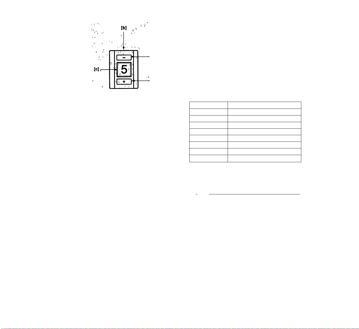
Fig. 2.3 SCSI ID Switch on the rear of the LS-10E
Scanner
Seiecteur d’lD SCSI à l’arrière du LS-10E
SCSI-Adressenschalter an der Riickseite des
Scanners LS-10E
Determining which ID to use
If the scanner is the only SCSI device that will sit on the
SCSI bus, there is no need to change the SCSI ID from
the preset value.
If the scanner must share the SCSI bus with one or
more other peripherals, it is necessary to insure that no
two peripherals have the same ID. Create a list of SCSI
peripherals (see Table 2.1) on the desired bus, noting
the device type and the SCSI ID of that device. To
determine the SCSI ID of the other peripherals, check
the rear of each peripheral for some indication of the
SCSI ID of that device. If there is no indication as to the
ID number, then consult with the peripheral’s user's
manual or call the peripheral manufacturer to determine
the SCSI ID setting.
, -SCSI ID
0
1
2
3
4
5
6
7
Table 2.1 Typical SCSI ID chart
,, Device Type
Computer (default)
LS-10 Scanner (default)
18
fWarnlri^i * 1 ,f* ■ • ''
Never change the SCSI,ID of a,,device with the.
pomputeriiiunning. ' ’ ’ , "
’ i
________
* " y “ ^ ‘ i! A. ’
If another SCSI peripheral shares the same SCSI ID as
the scanner, change the SCSI ID of the scanner to an
unused SCSI ID as indicated in the following section.
Note any changes in Table 2.1.
Setting the SCSI ID on the LS-10E scanner
The SCSI ID is set via a switch on the back of the
scanner as shown in Figure 2.3. Simply push the button
below the SCSI ID number indicator to increment the
SCSI ID. Similarly, push the button above the indicator
to decrement the SCSI ID.
[a] Top button (push to decrement)
[b] SCSI ID switch
[c] SCSI ID # indicator
[d] Bottom button (push to increment)
........
.........
Page 19

Détermination de i’ID
Si le scanner est le seul périphérique connecté au bus
SCSI, Il est inutile de modifier cette ID préréglée.
Si le scanner doit cohabiter sur le bus SCSI avec
d'autres périphériques, il est nécessaire de vérifier que
deux périphériques ne reçoivent pas la même ID SCSI.
Établissez une liste de vos périphériques sous la forme
du tableau 2.1.
L’ID SCSI peut être relevée sur la face arrière de la
plupart des périphériques. Si vous ne trouvez pas
d'indication de numéro d'ID, consultez leurs notices
respectives ou contactez le fabricant ou distributeur.
ID SCSI
0 Unité centrale (par défaut)
1
2
3
4
5
6
7
Tableau 2.1 Tableau ID SCSI
Attention!''■ ''
Ne jamais modifier l’ID SCSI d’un périphérique
pendant le fonctionnement de l’unité centrale.
Si un autre périphérique SCSI a la même ID SCSI que le
scanner, modifiez MD SCSI du scanner pour lui attribuer
une ID SCSI libre comme indiqué dans les sections
suivantes. Notez ces modifications dans le tableau 2.1.
Scanner LS-10 (par défaut)
Équipement
Ermittiung der einzusteilenden Adresse
Wenn der Scanner das einzige SCSI-Gerät auf dem
SCSI-Bus ist, besteht keine Veranlassung, die
eingestellte SCSI-Adresse zu ändern.
Muß sich der Scanner mit einem oder mehreren
Peripheriegeräten den SCSI-Bus teilen, muß
sichergestellt werden, daß die Adressennummern nicht
doppelt vergeben sind. Machen Sie deshalb eine
Aufstellung der SCSI-Pheripheriegeräte (siehe Tabelle
2.1) auf dem betreffenden Bus, der die entsprechenden
Gerätetypen und SCSI-Adressen zu entnehmen sind. Um
die SCSI-Adresse anderer Peripheriegeräte
festzustellen, überprüfen Sie die Rückseite jedes
Peripheriegerätes auf das Vorhandensein einer SCSIAdressenanzeige. Ist eine Adresse nicht bekannt,
schlagen Sie bitte im Handbuch des betreffenden
Peripheriegeräts nach oder konsultieren Sie den
Gerätehersteller.
SCSI-Adresse
0
1
2
3
4
5
6
7
Tabelle 2.1 Aufstellung der SCSI-Adressen
Achtung!
ijiijidern Sie die Einstellung ^der SCSI-Ac|r,esse
keinesfalls bei lautendem Сотри,terl , "i '' i
Computer (Vorgabe)
Scanner LS-10 (Vorgabe)
Gerätetyp
Sélection d’ID SCSI sur le Scanner LS-10E
L'ID SCSI est déterminée par un commutateur situé sur
la face arrière du scanner, comme indiqué figure 2.3.
Appuyer sur le bouton situé au dessous de l’indicateur
de numéro d'ID SCSI pour incrémenter et sur celui du
dessus pour décrémenter.
[a] Bouton supérieur (appuyer pour décrémenter)
[b] Commutateur d’ID SCSI
[c] Indicateur de numéro d’ID SCSI
[d] Bouton inférieur (appuyer pour incrémenter)
Sollte ein anderes SCSI-Peripheriegerät dieselbe
Adresse haben wie der Scanner, so ändern Sie die
Einstellung der SCSI-Adresse des Scanners wie
nachstehend beschrieben. Notieren Sie jede Änderung
in Tabelle 2.1.
Einstellung der SCSI-Adresse am
externen Scanner (LS-10E)
Die SCSI-Adresse wird wie in Abb. 2.3 dargestellt über
einen Schalter an der Rückseite des externen Scanners
eingestellt. Zur Einstellung einer höheren Zahl drücken
Sie die Taste unter der Adressenanzeige, zur
Einstellung einer niedrigeren die Taste über der
Anzeige.
[a] Obere Taste (Einstellung einer niedrigeren Zahl)
[b] SCSI-Adressenschalter
[c] SCSI-Adressenanzeige
[d] Untere Taste (Einstellung einer höheren Zahl)
19
Page 20
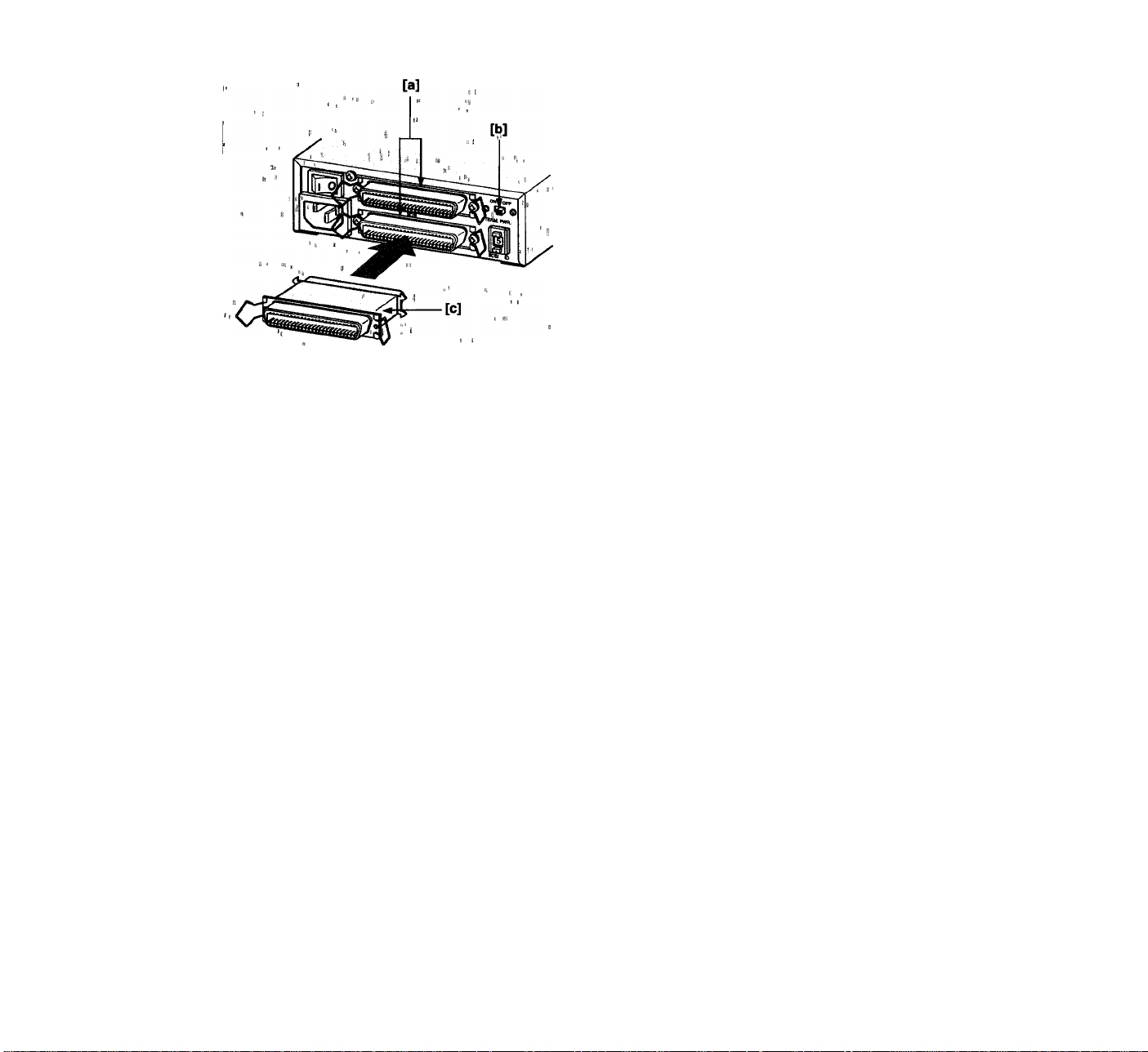
Fig. 2.4 SCSI termination on the rear of the LS-10E
scanner
Terminaison SCSI à l’arrière du scanner
LS-10E
SCSI-AbschluB an der Riickseite des
Scanners LS-10E
2-3 Terminating the SCSi Chain
The SCSI chain is an electrical bus connecting two or
more devices. It is critical that this bus be correctly
terminated for the SCSI peripherals to work properly.
Termination is an electronics term that applies to the
impedance found at both ends of the bus. The electrical
signals on the SCSI bus are changing rapidly between
their digital “on” and “off” states. To minimize noise, a
terminator is placed at each end of the bus. The effects
of this termination may be subtle, but are critical.
"Warning! ’ j "
Incorrect SCSI termination can cause unpredictable
Typically, the computer sits as one end of the SCSI bus.
Assuming this is the case, the SCSI controller in the
computer has to be terminated.
If another SCSI peripheral shares this SCSI bus, it also
has to be terminated. If additional SCSI devices sit on
the bus in between the two end SCSI devices, these
devices can NOT be terminated. Only two terminated
devices can reside on the SCSI bus, one at each end.
Terminating an LS-10E
The LS-10E scanner box is configured with two 50-pin
SCSI connectors on the rear of the LS-10E unit as shown
in Figure 2.4. Install the standard 50-pin SCSI terminator
onto the bottom connector if termination is desired. If
the LS-10E sits in the center of a SCSI chain, then by
necessity, the bottom connector will be used for a SCSI
terminator.
[a] SCSI connectors
[b] TERM. PWR. switch
[c] SCSI terminator
Term. Power Switch
If the terminator-power is supplied by the other
connected peripherals, always turn off the “TERM.
PWR” switch on the rear panel.
If it is not so supplied, always turn on the switch.
ON: Supplies SCSI terminator-power
OFF: Stops supplying SCSI terminator-power
20
Page 21

2-3 Terminaison de ia chaîne SCSI
2-3 Abschluß der SCSI-Kette
La chaîne SCSI est un bus électrique reliant deux
périphériques ou pius. Pour que les périphériques SCSI
puissent fonctionner correctement, il est essentiel que la
terminaison soit correctement effectuée.
"Terminaison” est un terme d’électronique qui
s’applique à l’impédance des deux extrémités du bus.
Les signaux électriques sur le bus SCSI passent
rapidement entre les niveaux “haut” et "bas”. Pour
réduire le bruit au minimum, une terminaison est placée
à chaque extrémité du bus. Les effets de cette
terminaison sont essentiels.
Attention! ’ ■ " ‘ '
Une terminaison SCSi incorrecte peut provoquer des
erreurs imprévisibles.
Typiquement, l’unité centrale se trouve à l’une des
extrémités du bus SCSI. Le contrôleur SCSI dans l’unité
centrale est alors muni d’une terminaison.
Si un autre périphérique SCSI partage ce bus SCSI, il
doit lui aussi recevoir sa terminaison. Si des
périphériques SCSI additionnels se trouvent sur le bus
entre deux périphériques, ces périphériques NE
PEUVENT PAS recevoir de terminaison.
Autrement dit, seules deux extrémités du bus SCSI sont
munies de terminaisons.
Terminaison d’un LS-10E
Le boîtier du scanner LS-10E comporte à l’arrière deux
connecteurs SCSI de 50 broches, comme le représente
la figure 2.4. Installez le bouchon de terminaison
standard à 50 broches sur le connecteur inférieur si une
terminaison est nécessaire. Si le scanner fait partie
d’une chaîne de dispositifs SCSI, le bouchon de
terminaison sera utilisé sur le dernier dispositif.
[a] Connecteurs SCSI
[b] Interrupteur Term. PWR
[c] Bouchon de terminaison SCSI
interrupteur Term. Power
Si l’alimentation de la terminaison est fournie par les
autres périphériques, placez l’Interrupteur “TERM.
PWR” situé sur le panneau arrière sur OFF.
Si elle n’est pas fournie par les autres périphériques,
placez-le sur ON.
ON: Fournit l’alimentation de terminaison SCSI.
OFF: Coupe l’alimentation de terminaison SCSI.
Bei der SCSI-Kette handelt es sich um einen
elektrischen Bus zwischen zwei oder mehreren Geräten.
Dieser Bus muß auf jeden Fall entsprechend terminiert
sein, damit die SCSI-Peripheriegeräte einwandfrei
arbeiten können.
Bei “Abschluß” handelt es sich um einen elektronischen
Fachausdruck, der sich auf den Widerstand an beiden
Enden eines Busses bezieht. Die elektrischen Signale
auf dem SCSI-Bus wechseln in schneller Folge zwischen
dem digitalen EIN- und AUS-Zustand. Um das Rauschen
auf ein Minimum zu verringern, wird der Bus an beiden
Enden abgeschlossen. Der Effekt eines solchen
Abschlusses mag gering sein, er ist jedoch wichtig.
Achtung! •
Falscher SCSI-Abschluß kann unvorhersehbare
Feh!er verursachen!
Normalerweise befindet sich der Computer an einem
Ende des SCSI-Busses. Sofern dies der Fall ist, muß der
SCSI-Controller im Computer terminiert werden.
Sollte ein weiteres SCSI-Peripheriegerät diesen SCSI-
Bus teilen, muß auch dieses abgeschlossen werden.
Befinden sich weitere SCSI-Geräte auf dem Bus
zwischen den beiden vorgenannten SCSI-Geräten, so
können diese NICHT terminiert werden. Am SCSI-Bus
können sich nur zwei Abschlußschaltungen befinden,
eine an jedem Ende.
Abschluß eines LS-10E
An der Rückseite des LS-10E befinden sich - wie in Abb.
2.4 dargestellt - zwei 50polige SCSI-Steckverbinder.
Bringen Sie den normalen 50poligen SCSI-
Abschlußwiderstand gegebenenfalls im unteren
Anschluß an. Befindet sich der LS-10E in der Mitte der
SCSI-Kette, ist der untere Anschluß zwangsläufig mit der
SCSI-Leitungsbrücke besetzt.
[a] SCSI-Stecker
[b] Abschlußstromschalter (TERM. PWR)
[c] SCSI-Abschlußwiderstand
Abschlußstromschalter
Falls der Abschlußstrom durch die anderen
angeschlossenen Peripheriegeräte geliefert wird, stellen
Sie den Abschlußstromschalter (TERM. PWR) an der
Rückseite des Gerätes grundsätzlich auf OFF (AUS).
Wird der Strom nicht so geliefert, stellen Sie den
Schalter stets auf ON (EIN).
ON (EIN): SCSI-Abschlußstrom wird geliefert
OFF (AUS): SCSI-Abschlußstrom wird nicht geliefert
21
Page 22
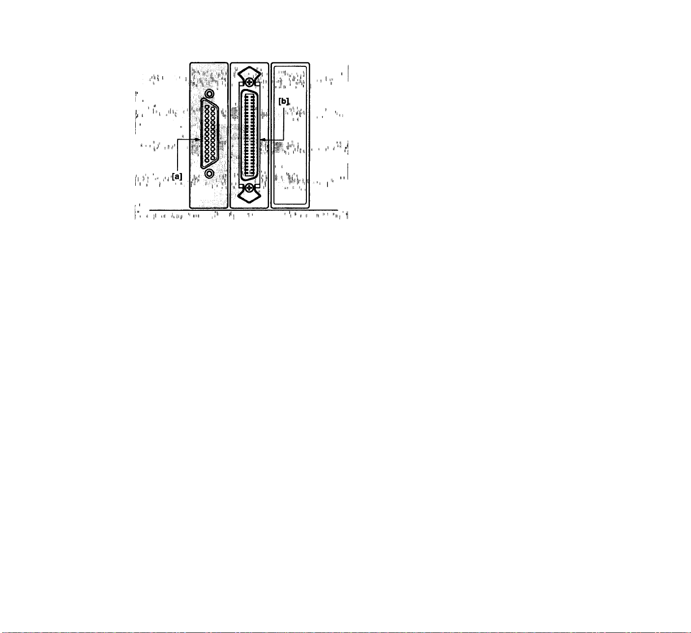
Fig. 2.5 Typical SCSI connectors on the rear of the
computer
Connecteurs SCSI à l’arrière d’une unité
centrale
Typische SCSI-Stecker an der Rückseite eines
Computers
2-4 Connecting to the Computer
SCSI
The SCSI port on the computer is a connector found
either inside the computer or on the rear panel of the
computer. There are three basic types of SCSI
connectors dealt with in this manuai.
The three types of SCSi connectors discussed in this
manual are the 50-pin internai connector, external 25-pin
DB25-type connector or 50-pin external Centronics
connector.
Warning!
Thp,SCSl'cpnnectpr should neyei; be connected or
unconnecteld while tlie computer is running. ■ • •
Connecting to the inside of a computer
The External SCSI Connector
There are two typical SCSI connectors on computers.
The first is the 25-pin DB25 connector. This is the
standard connector used on the Macintosh computers. It
is a female connector, as shown in Figure 2.5 [a], and is
similar to the printer port connector. Do not confuse one
of the printer port connectors on the computer with the
SCSI connector should this type of connector be used.
The 50-pin Centronics connector is the most common
connector used for external SCSI connections on the
IBM-type PC computers. This connector is shown in
Figure 2.5 [b].
[a] 25-pin DB25 SCSI Connector
[b] 50-pin Centronics SCSI Connector
22
Page 23

2-4 Connexion SCSI à l’unité
centraie
Le port SCSI de l'ordinateur est un connecteur situé à
l’intérieur ou sur le panneau arriére de l’unité centrale.
Ce manuel traite de trois types de connecteurs SCSI.
Trois types différents de connecteurs SCSI nous
intéressent pour le raccordement du scanner: 50
broches en ligne (internes), 25 broches DB-25 et 50
broches Centronics (externes).
Attention! ' ‘ '
Ne branchez et ne débranchez Jamais un connecteur
SCSi pendant te fonctionnethént de ü’unité,.centraie.' <
Connexion à l’intérieur de l’unité centrale
Connecteur SCSI externe
Les unités centrales peuvent être munies de deux types
de connecteurs SCSI. Le premier est le connecteur
DB25 à 25 broches qui est le connecteur standard des
Macintosh. C’est un connecteur femelle tel que le
représente la figure 2.5 [a] similaire au connecteur du
port d’imprimante. Il faut donc veiller à ne pas le
confondre avec les ports d’imprimante de l’unité
centrale.
Le connecteur Centronics à 50 broches est le
connecteur le plus communément utilisé pour les
connexions SCSI externes sur les ordinateurs de type
IBM PC. Ce connecteur est représenté à la figure 2.5 [b].
[a] connecteur 25 broches DB-25
[b] connecteur 50 broches Centronics SCSI
2-4 Anschluß an die SCSi-
Schnittstelie des Computers
Der SCSI-Anschluß des Computers befindet sich
entweder im Inneren oder an dessen Rückseite. In
diesem Handbuch werden drei Grundtypen von SCSISteckverbindern behandelt.
Bei den drei in diesem Handbuch besprochenen SCSISteckverbindern handelt es sich um den 50poligen
Innensteckverbinder, den 25poligen
Außensteckverbinder DB25 und den 50poligen
Centronics-Außensteckverbinder,
-Achtung^,,, ,
ScJiließen Sie den SCSI-Steckverbinder nie bei
iaufendem Computer an! , , ,
iij
i,'i
J,.,:
.....
!i‘i|. '
Anschluß Im Innern des Computers
Der äußere SCSI-Steckverbinder
Es gibt zwei typische SCSI-Steckverbinder an
Computern. Der erste ist der 25polige DB25Steckverbinder. Dies ist der Standard-Steckverbinder an
Macintosh-Computern. Es ist eine Steckerbuchse (siehe
Abb. 2.5 [a]), die dem Druckeranschluß ähnelt.
Verwechseln Sie keinesfalls einen der
Druckeranschlüsse des Computers mit dem SCSISteckverbinder!
Der 50polige Centronics-Steckverbinder ist der
gebräuchlichste Steckverbinder für äußere SCSIAnschlüsse an IBM-kompatiblen PCs. Er ist in Abb. 2.5
[b] dargestellt.
[a] 25poliger SCSI-Steckverbinder DB25
[b] 50poliger SCSI-Steckverbinder von Centronics
23
Page 24
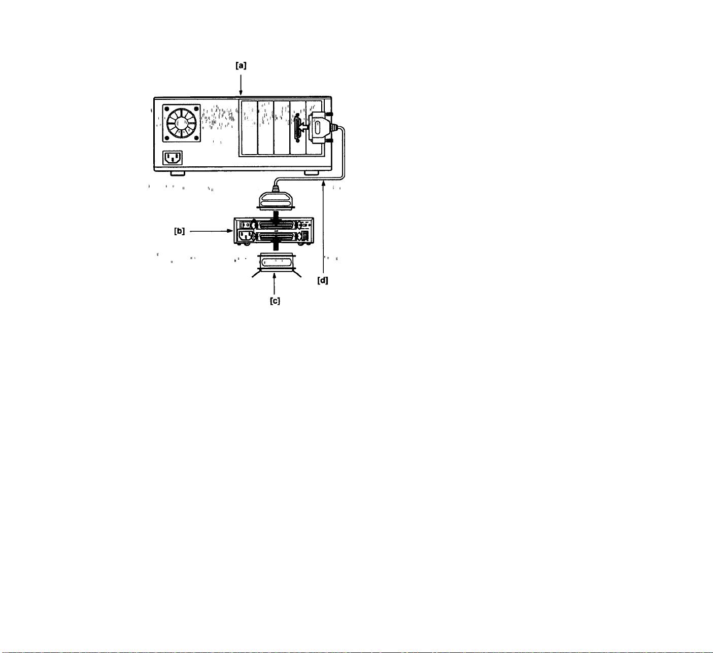
Fig. 2.6 Two SCSI devices on the SCSI bus
Deux dispositifs SCSI sur le bus SCSI
Zwei SCSI-Gerate auf dem SCSI-Bus
2-5 Setting Up the SCSI Chain
The SCSI chain is the electronic data and control bus
that connects two or more SCSI devices. As mentioned
at the start of this chapter, the SCSI chain can have
multiple devices on the bus. Thus, the name “chain”
implies the connection of these devices.
On any SCSI bus, there must be at least one SCSI
initiator and one SCSI target. The LS-10E scanner is
always a SCSI target device. This is the standard for
SCSI scanners. Most peripherals connected to
computers will be SCSI targets. Typically, the computer
will be the SCSI initiator.
In certain cases, there can be more than one initiator on
a bus, and in fact there are times when a computer can
be an SCSI target device. These cases are rare and are
not covered in this manual.
In each case, the SCSI ID's of each device must be
unique.
Two SCSI devices
In the simplest case, only two devices share the SCSI
chain. These are referred to as the SCSI initiator and
the SCSI target. In our case, the SCSI initiator is the
computer and the SCSI target is the scanner. This
simple configuration is shown in Figure 2.6.
[a] Computer SCSI initiator (internally terminated)
[b] Scanner SCSI target
[c] SCSI terminator
[d] SCSI cable
In this case, both the SCSI initiator side of the bus and
the SCSI target side of the bus have to be terminated,
as shown in Figure 2.6.
24
Page 25

2-5 Établissement de la chaîne
SCSI
_______________________
La chaîne SCSI est un bus de données électroniques et
de commande reliant deux périphériques SCSI ou plus.
Comme il a été indiqué au début du chapitre, la chaîne
SCSI peut comporter plusieurs dispositifs sur le bus. Le
terme “chaîne” désigne la liaison de ces périphériques.
Sur un bus SCSI, il doit y avoir au moins un maître SCSI
et un esclave SCSI. Le scanner LS-10E est toujours un
esclave SCSI. C'est la norme pour les scanners SCSI.
La plupart des périphériques reliés à l'unité centrale
sont des esclaves SCSI. L’unité centrale est
généralement le maître SCSI.
Dans certains cas, il peut y avoir plusieurs maîtres sur
un bus ; parfois, l'unité centrale peut être un esclave
SCSI. Ces cas sont rares et ne sont pas traités dans le
présent manuel.
Dans tous les cas, la règle à respecter absolument est
l’attribution à chaque dispositif d’une ID SCSI unique.
Deux dispositifs SCSi
Dans le cas le plus simple, seulement deux dispositifs
SCSI constituent la chaîne. Ils sont désignés comme
maître et esclave. Dans le cas traité l'unité centrale est
le maître et le scanner, l'esclave. Cette façon très
simple d’interfacer deux dispositifs est montrée figure
2.6.
[a] Unité centrale Maître SCSI (terminaison
intérieure)
[b] Scanner Esclave SCSI
[c] Terminaison SCSI (bouchon)
[d] Câble SCSI
Dans ce cas, les deux extrémités du bus SCSI doivent
recevoir une terminaison, comme indiqué sur la figure
2.6.
2-5 Aufbau der SCSI-Kette
Bei der SCSI-Kette handelt es sich um den
elektronischen Daten- und Steuerbus, der zwei oder
mehr SCSI-Geräte verbindet. Wie bereits zu Beginn
dieses Kapitels erwähnt, können sich innerhalb der
SCSI-Kette mehrere Geräte auf dem Bus befinden. Somit
bezieht sich die Bezeichnung ‘‘Kette’’ auf die
Verbindung dieser Geräte.
Auf jedem SCSI-Bus muß sich mindestens ein SCSIHauptgerät und ein SCSI-Nebengerät befinden. Der
Scanner LS-10E ist stets das SCSI-Nebengerät. Dies ist
normal für SCSI-Scanner. Bei den meisten an einen
Computer angeschlossenen Peripheriegeräten handelt
es sich um SCSI-Nebengeräte. Im Normalfall ist der
Computer das SCSI-Hauptgerät.
In manchen Fällen kann sich mehr als ein Hauptgerät
auf einem Bus befinden, und es kann auch verkommen,
daß ein Computer zum SCSI-Nebengerät wird. Dies ist
jedoch nur selten der Fall, so daß hier nicht darauf
eingegangen wird.
In jedem Fall darf die SCSI-Adresse jedes Geräts nur
einmal vergeben sein.
_________
Zwei SCSI-Geräte
Im einfachsten Fall befinden sich nur zwei Geräte in der
SCSI-Kette. Diese gelten als SCSI-Hauptgerät und SCSINebengerät. In unserem Fall Ist das SCSI-Hauptgerät
der Computer und das SCSI-Nebengerät der Scanner.
Diese einfache Anordnung ist in Abb. 2.6 dargestellt.
[a] Computer, SCSI-Hauptgerät (intern
abgeschlossen)
[b] Scanner, SCSI-Nebengerät
[c] SCSI-Abschluß
[d] SCSI-Kabel
In diesem Fall muß der Bus sowohl auf der Seite des
SCSI-Hauptgeräts als auch auf jener des SCSINebengeräts terminiert werden. Dies ist in Abb. 2.6
dargestellt.
25
Page 26

( -
. )
— —
Fig. 2.7 Multiple SCSI devices on the SCSI bus
The LS-10E is shown at the end of the chain.
Dispositifs multiples sur un bus SCSI
Le scanner LS-10E est positionné en fin de
chaîne.
Mehrere SCSI-Geräte auf dem SCSI-Bus
Der Scanner LS-10E befindet sich hier am Ende
der Kette.
Multiple SCSI devices in chain
Often more than one SCSI target device wiil be hooked
up to the SCSI bus. When this is true, the chain of
cabies must connect each device together, even though
the devices will typically only communicate with the
computer. This chaining, as shown in Figure 2.7,
minimizes the number of cables and connectors.
[a] Computer-SCSI master (internally terminated)
[b] SCSI cable
[c] Optional peripheral-SCSI target
[d] Scanner-SCSI target
[e] SCSI terminator
[f] SCSI cable
In the case shown in Figure 2.7, the LS-10E scanner is
installed at the end of the SCSI chain, opposite of the
computer. Since the LS-10E is at the end of the chain it
has to be terminated. Since the computer is at the other
end of the chain, it also has to be terminated. No other
SCSI devices on the chain can be terminated in this
configuration.
It is equally possible to configure the SCSI chain with
the LS-10E in the center of the chain. In this case, the
SCSI terminator would reside on the optional peripheral,
as opposed to the LS-10E.
2-6 Setting Up a SCSI Chain with
the LS-10E
The LS-10E scanner can easily sit in the center or at the
end of a SCSI chain. The two 50-pin connectors at the
rear of the LS-10E are both used for this purpose.
Something must always be plugged into each of these
two connectors. For the LS-10E plugged into the center
of the SCSI chain, two SCSI cables must be plugged into
them, one going to each neighboring SCSI device. In the
case that the LS-10E is at the end of the SCSI chain,
then one connector will have a SCSI cable in it. This
cable will connect the LS-10E to the SCSI bus. The other
connector will have a SCSI terminator plugged into it
since it is at the end of the SCSI chain.
26
Page 27

Chaîne SCSI à dispositifs multipies Mehrere SCSI-Geräte in der Kette
Souvent, plus d'un dispositif esclave SCSI sera relié au
bus SCSI. Dans ce cas, les dlspostlfs sont reliés les uns
aux autres par des cordons uniques, ce qui minimise le
nombre de câbles et de connecteurs, comme le montre
la figure 2.7. Chacun de ces dispositifs, cependant,
communique uniquement avec l’unité centrale.
[a] Unité centrale Maître SCSI terminaison
intérieure
[b] Câble SCSI
[c] Autre périphérique Esclave SCSI
[d] Scanner Esclave SCSI
[e] Terminaison SCSI (bouchon)
[f] Câble SCSI
Dans le cas de la figure 2.7, le scanner LS-10E est
installé en bout de chaîne SCSI, â l’opposé de l’unité
centrale. Il doit dans ce cas recevoir un bouchon de
terminaison, comme nous l’avons vu plus haut. L’unité
centrale étant à l’autre bout de la chaîne, doit également
recevoir un bouchon de terminaison. Aucun autre
dispositif de cette chaîne n’a à recevoir de terminaison.
Il est bien sûr possible de positionner le scanner LS-10E
en milieu de chaîne. Dans ce cas, le bouchon de
terminaison sera connecté à un autre périphérique au
lieu du LS-10E.
2-6 Intégration du LS-10E à la
Oft wird mehr als ein SCSI-Nebengerät an den SCSI-Bus
angeschlossen. Ist dies der Fall, muß die Kabelkette
sämtliche Geräte miteinander verbinden, wenngleich die
Geräte normalerweise nur mit dem Computer
kommunizieren. Diese Verkettung ist in Abb. 2.7
dargestellt. Sie verringert die Anzahl der Kabel und
Stecker auf ein Minimum.
[a] Computer, SCSI-Hauptgerät (intern
abgeschlossen)
[b] SCSI-Kabel
[c] Optionales Peripheriegerät, SCSI-Nebengerät
[d] Scanner, SCSI-Nebengerät
[e] SCSI-Abschluß
[f] SCSI-Kabel
In dem in Abb. 2.7 gezeigten Fall befindet sich der
Scanner LS-10E am Ende der SCSI-Kette, gegenüber
dem Computer. Nachdem der Scanner LS-10E das Ende
bildet, muß er abgeschlossen werden. Da der Computer
das andere Ende der SCSI-Kette darstellt, muß er
ebenfalls terminiert werden. In dieser Konfiguration
kann kein weiteres SCSI-Gerät in der Kette terminiert
werden.
Es ist auch möglich, die SCSI-Kette so aufzubauen, daß
sich der Scanner LS-10E in der Mitte befindet. In diesem
Fall würde sich der SCSI-Abschlußwiderstand nicht am
LS-10E befinden, sondern am optionalen
Peripheriegerät.
chaîne SCSI
Le scanner LS-10E peut être positionné au milieu ou en
bout de la chaîne SCSI. Les connecteurs à 50 broches
au dos du LS-10E sont tous deux destinés à cette fin. Il
doit toujours y avoir quelque chose de branché à ces
deux connecteurs. Si le LS-10E est au milieu de la
chaîne SCSI, les deux câbles SCSI doivent être
branchés â ces connecteurs, chacun de ces câbles
allant au SCSI voisin. Si le LS-10E est en bout de
chaîne, l’un des connecteurs reçoit le câble SCSI qui
relie le LS10E au bus SCSI. L’autre reçoit un bouchon
de terminaison puisqu’il se trouve à l’extrémité de la
chaîne SCSI.
2-6 Aufbau einer SCSI-Kette mit
dem LS-10E
Der Scanner LS-10E kann sich ohne weiteres in der
Mitte oder am Ende einer SCSI-Kette befinden. Die
beiden SOpoligen Steckverbinder an der Rückseite des
LS-10E dienen beide zu diesem Zweck. An beide muß
stets etwas angeschlossen sein. Befindet sich der
LS-10E in der Mitte der SCSI-Kette, müssen zwei SCSIKabel angeschlossen sein, von denen je eines zu den
benachbarten SCSI-Geräten geht. Befindet sich der
LS-10E am Ende der SCSI-Kette, muß ein SCSI-Kabel an
einen der Steckverbinder angeschlossen sein. Dieses
Kabel verbindet den LS-10E mit dem SCSI-Bus. Im
anderen Steckverbinder muß sich ein SCSIAbschlußwiderstand befinden, nachdem es sich hierbei
um das Ende der SCSI-Kette handelt.
27
Page 28

Fig. 3.1 The LS-10 scanner front view
Face avant du LS-10
Vorderansicht des Scanners LS-10
ra
Setting Up the Internal-mount Model (LS-10)
The LS-10 scanner is easy to install. The following
instructions will lead you through this process.
3-1 Setting Up the LS-10 Scanner
Let’s take a look at the LS-10 internal-mount scanner as
shown in Figure 3.1. Note that the face of the LS-10 is
identical to the LS-10E scanner. The front of the scanner
includes the film slot, the focus control and the active
indicator.
[a] Insert slide here
[b] Active indicator
[c] Focus control
Rear panel
The rear panel of the LS-10 is shown in Figure 3.2. Note
that there are three items of interest on the rear panel.
These are the DC power connector, SCSI connector and
configuration DIP switch block.
[d] SCSI connector
[e] Configuration DIP switch
[f] Power connector
The default DIP switch configuration is shown in Table
3.1. The meaning of the SCSI termination and the SCSI
ID DIP switch is discussed in this chapter. The LS-10
scanner is set at the factory to SCSI ID #5 and to
termination OFF. Note the connector on the right side of
the rear view of the LS-10 as shown in Figure 3.2. [t]
connector is unused when connecting the LS-10 inside
the computer.
Fig. 3.2 The LS-10 scanner rear view
Face arrière du LS-10
Rückseite des Scanners LS-10
28
DIP
Switch
1
2 open SCSI ID bit 1 = 0
3 closed
4 open SCSI ID Termination = OFF
Table 3.1 Factory set default DIP switch
Default Usage
closed
configuration
SCSI ID bit 0 = 1
SCSI ID bit 2 = 1
Page 29

Montage du modèle interne
Anschluß des Einbaumodells
(LS-10)
Le scanner LS-10 est facile à installer. Ces instructions
doivent vous aider à réaliser son intégration dans l'unité
centrale.
3-1 Préparation du scanner LS-10
La figure 3.1 montre que la face avant du scanner LS-10
est en tous points identique au scanner LS-10E, avec le
logement film, la molette de mise au point, et le voyant
d’activité.
[a] Insérez la diapositive ici
[b] Voyant d'activité
[c] Molette de mise au point
Panneau arrière
La face arrière du LS-10 est illustrée figure 3.2. On y
trouve le connecteur d’alimentation en courant continu,
le connecteur SCSI et les interrupteurs DIP de
configuration.
Id] Connecteur SCSI
[e] Interrupteurs DIP
[f] Connecteur d’alimentation
La configuration par défaut des interrupteurs DIP est
indiquée au tableau 3.1. La terminaison SCSI et
l’interrupteur DIP pour l’ID SCSI sont expliqués dans ce
chapitre. Le Scanner LS-10 a été réglé en usine sur l’ID
SCSI = 5 et sur la terminaison désactivée. Notez le
connecteur du côté droit de la vue arrière du LS-10
représenté sur la figure 3.2 [f]. Ce connecteur n’est pas
utilisé lorsque le LS-10 est monté à l’intérieur de
l’ordinateur.
Inter
rupteur
DIP
1
2
3 fermé
4
Tableau 3.1 Configuration par défaut réglée en usine
Défaut '
fermé
ouvert
ouvert
de l’interrupteur DiP
K ,,
Utilisation
ID SCSI bit 0 = 1
ID SCSI bit 1 = 0
ID SCSI bit 2 = 1
Terminaison ID SCSI
= désactivée
II
(LS-10)
Das Einbaumodell LS-10 ist leicht anzuschließen. Dieser
Anschluß ist im folgenden beschrieben.
3-1 Montage des Scanners LS-10
Abb. 3.1 zeigt die Frontplatte des Einbau-Scanners
LS-10, die mit jenem des externen Scanners LS-10E
identisch ist. Auf ihr befinden sich der Filmschlitz, die
Feinfokussierung und die Kontrollampe.
[a] Schlitz zum Einlegen des Dias
[b] Kontrollampe
[c] Feinfokussierung
Rückseite
Abb. 3.2 zeigt die Rückseite des LS-10. An dieser
befinden sich der Gleichstromanschluß, der SCSISteckverbinder und die DIP-Schalter.
[d] SCSI-Steckverbinder
[e] DIP-Schalter
ra Gleichstromanschluß
Tabelle 3.1 zeigt die vorgegebene DlP-SchalterEinstellung. Die Bedeutung des SCSI-Abschlusses und
der SCSI-Adressen-DIP-Schalter wird in diesem Kapitel
erläutert. Die werkseitige Einstellung des Scanners
LS-10 ist wie folgt: SCSI-Adresse = 5, SCSIAdreßabschluß = OFF (AUS). Beachten Sie den in der
Abb. 3.2 [f] gezeigten Steckverbinder auf der linken
Seite der Rückansicht des LS-10. Dieser Steckverbinder
bleibt unbenutzt, wenn der LS-10 im Inneren des
Computers angeschlossen wird.
DIP- '
Schalter
1 geschlossen
2
3 geschlossen SCSI-Adreßbit 2 = 1
4
Tabelle 3.1 Werkseitig vorgegebene DlP-Schalter-
Vorgabe
li
offen
offen
Elnstellung
SCSI-Adreßabschluß
III ' "il ä
Verwendung
1 1
SCSI-Adreßbit 0 = 1
SCSI-Adreßbit 1 = 0
= OFF (AUS)
29
Page 30

[C]
Fig. 3.3
[a]
The LS-10 scanner side view with raiis
Vue iatérale du LS-10 et rail guide de montage
Seitenansicht des Scanners LS-10 mit
Führungsschienen
[b]
Both sides of the LS-10 are identical as shown in Figure
3.3. Note the set of two tapped holes on each side. One
set of holes on each side of the scanner will be used for
the rails as shown in this figure.
[a] Mounting holes
[b] Guide rail
[c] Locking tab
[d] Top panel
[e] LS-10 front panel
[f] Tapped holes
3-2 Installing the LS-10 Scanner
Installing the internal-mount scanner is very easy. The
guide rails provided with the scanner must be screwed
to the two sides of the scanner. The scanner must be
inserted into the drive bay using the computer drive bay
slots. Connections to the back of the scanner include the
computer power and the SCSI flat cable.
Due to the tight space constraints inside the computer, it
is not possible to connect the cables to the scanner after
the scanner is installed. The SCSI cable and terminating
networks are easier to connect to the scanner before the
scanner is mounted in drive bay. The computer power
connector is typically easiest to connect to the scanner
when the scanner is partially pushed into the drive bay.
Installing the guide rails
Each computer can have its own special requirements
for mounting devices into the internal drive bays. In
most cases, a pair of guide rails are screwed to the
sides of the scanner to slide into the drive bay as shown
in Figure 3.3. These guide rails are also used to lock the
scanner in place.
30
The computer drive bays
In order for a scanner to be mounted internal to the
computer, the computer must have the following:
1. An externally accessible 5 1/4" half-height bay
2. A standard power supply connector
3. A card slot available on the motherboard
Page 31

Les deux côtés du LS-10 sont identiques comme ie
représente la figure 3.3. Notez les paires d’orifices
taraudés de chaque côté. Ces orifices servent au
montage des rails comme le représente la figure.
[a] Orifices de montage
[b] Rail guide
[c] Butée de verrouillage
[d] Panneau supérieur
[e] Face avant du LS-10
m Orifices taraudés
Beide Seiten des LS-10 sind identisch und in Abb. 3.3
dargestellt. Auf jeder Seite befinden sich zwei Paare von
Gewindelöchern. Eines dieser Paare pro Seite dient zur
Befestigung der abgebildeten Schienen.
[a] Montagelöcher
[b] Führungsschiene
[c] Sicherungsblech
[d] Deckplatte
[e] Frontplatte des LS-10
[f] Gewindebohrungen
3-2 Installation du scanner LS-10
L'installation interne du LS-10 est très simple. Les rails
guides fournis doivent être fixés de chaque côté du
scanner. Il suffira alors de le glisser dans le logement
de l’unité centrale, doté de glissières à cette fin. Les
raccordements électriques à effectuer à l’arrière du
scanner se résument à l’alimentation et au cordon en
nappe SCSI.
L’espace intérieur de l’unité centrale étant réduit, il
n’est pas possible de connecter les câbles au scanner
lorsque celui-ci est installé. Il est plus facile de
connecter le câble SCSI et les bouchons de terminaison
avant de monter le scanner dans le logement. Il est plus
facile de brancher le connecteur d’alimentation de
l’unité centrale au scanner lorsque celui-ci est
partiellement introduit dans le logement.
Montage des rails guides
Chaque unité centrale a ses spécificités en matière de
montage encastré de périphériques. La plupart du
temps, une paire de rails est fixée de chaque côté du
scanner, comme sur la figure 3.3, et le scanner glisse
comme un tiroir dans le logement. Ces rails servent
aussi au blocage du scanner en place.
Le iogement de l’unité centraie
Pour pouvoir intégrer un scanner LS-10 à une unité
centrale, celle-ci doit être dotée de:
1. un emplacement 5 1/4”, demi-hauteur, accessible de
l’extérieur
2. un connecteur d’alimentation standard
3. un emplacement pour carte disponible sur la carte
mère
3-2 Einbau des Scanners LS-10
Der Einbau des Scanners ist sehr einfach. Die mit dem
Scanner gelieferten Führungsschienen werden auf die
beiden Seiten des Scanners geschraubt. Der Scanner
wird über die entsprechenden Führungsschlitze in den
Laufwerkschacht des Computers eingesetzt. An der
Rückseite des Scanners werden das Spannungskabel
vom Computer und das SCSI-Flachkabel angeschlossen.
Auf Grund der räumlichen Enge innerhalb des
Computers ist es nicht möglich, die Kabel nach dem
Einbau in den Computer anzuschließen. Vielmehr ist es
leichter, das SCSI-Kabel und die Abschlußwiderstände
vor dem Einbau des Scanners in den Laufwerkschacht
anzuschließen. Der Spannungsstecker des Computers
läßt sich meist am leichtesten an den Scanner
anschließen, wenn dieser zum Teil in den
Laufwerkschacht eingeführt ist.
Montage der Führungsschienen
Die Montage von Geräten im Laufwerkschacht kann in
den verschiedenen Computern unterschiedlich gelöst
sein. In den meisten Fällen kann der Scanner wie in
Abb. 3.3 gezeigt auf zwei angeschraubten
Führungsschienen in den Laufwerkschacht geschoben
werden. Diese Führungsschienen dienen auch zur
Fixierung des Scanners im Computer.
Die Computer-Laufwerkschächte
Damit der Scanner in einen Computer eingebaut werden
kann, muß dieser über folgende 'Voraussetzungen
verfügen:
1. Von außen zugänglicher, halbhoher
5 1/4”-Laufwerkschacht
2. Normaler Stromversorgungsstecker
3. Kartenschlitz auf der Grundplatine
31
Page 32

Fig. 3.4 A typical computer drive bay slot
(The drive bay as seen from the front)
Emplacement typique 5 1/4” demi hauteur, vu
de ¡’avant
Ein typischer Computer-Schachteinschub
(Vorderansicht des Laufwerkschachts)
The scanner will slide into a 5 1/4” half-height drive bay
as shown in Figure 3.4. Since you will be inserting film
into the scanner, the computer must have a cutout for
this drive bay. In other words, the drive bay must be
externally accessible. The scanner will be powered from
the computer using the standard computer drive power
supply connector. The computer motherboard needs to
have an available single short connector slot for the
SCSI interface board.
[a] Rail slots
[b] Rail stop screws
[c] Rail stop (open)
[d] Drive slot
[e] Insert LS-10 here
[f] Rail stop (closed)
The computer drive bay has one or two metal stops
screwed into the tapped holes on the sides of each half
height drive slot as shown in Figure 3.4. These should
be loosened to allow them to either be removed or hung
freely so they do not block the drive bay receptacles for
the guide rails. These will be repositioned after the
scanner is installed to lock the scanner in place.
The scanner side mounting holes
Two sets of vertical holes are provided on the sides of
the scanner. These are called the top and bottom rail
mounting holes. One set must be chosen in accordance
with where the computer allows the scanner to be
positioned in the drive bay. Most computers require that
the bottom set of mounting holes be used. Position the
rails at the bottom of the scanner and, while holding the
scanner, see if the scanner will slide into the bay rail
slots.
32
Page 33

Le scanner se glisse dans le logement 5 1/4”, demihauteur comme sur la figure 3.4. Comme vous devez
introduire le film dans le scanner, l'unité centrale doit
être dotée d'une fente pour ce logement qui devra être
accessible de l'extérieur. Le scanner sera alimenté par
le connecteur standard d'alimentation interne. La carte
mère de l'unité centrale doit disposer d'un emplacement
libre pour y insérer une carte d’interface SCSI.
[a] Rainures
[b] Vis de taquet
[c] Taquet (ouvert)
[d] Emplacement
[e] Insérer le LS-10 ici
[I] Taquet (fermé)
Le logement de l’unité centrale comporte un ou deux
taquets métalliques vissés dans les orifices sur les
côtés de chaque fente comme le représente la figure
3.4. Dévissez les vis et retirez les taquets ou laissez-les
pendre librement de sorte que les rails guides puissent
passer librement. Après avoir posé le scanner, remettez
les taquets en place pour bloquer le scanner.
Alésages latéraux du scanner
Deux séries d’alésages filetés sont pratiqués de chaque
côté du scanner LS-10. Il servent à fixer les rails guides,
soit en position haute, soit en position basse. Choisissez
la série de trous qui permet de monter correctement le
scanner dans l’unité centrale. La plupart des unités
centrales requièrent un montage des rails en position
basse. Montez les rails guides en position basse, et
présentez le LS-10 face au logement pour vérifier qu'il y
entre facilement.
Der Scanner wird gemäß Abb. 3.4 in den halbhohen
5 1/4”-Laufwerkschacht geschoben. Nachdem Film in
den Scanner eingeführt werden muß, muß der Computer
über eine Aussparung für diesen Laufwerkschacht
verfügen. Mit anderen Worten, der Laufwerkschacht muß
von außen zugänglich sein. Der Scanner wird über
einen normalen Stecker vom Computer mit Spannung
versorgt. Auf der Grundplatine muß sich ein freier
Steckschlitz für die SCSI-Schnittstellenkarte befinden.
[a] Schienenschlitze
[b] Schienenanschlagsschrauben
[c] Schienenanschlag (offen)
[d] Laufwerkeinschub
[e] LS-10 hier einschieben
[<] Schienenanschlag (geschlossen)
Wie Abb. 3.4 zeigt, befinden sich ein oder zwei
Metallanschläge in Gewindelöchern an der Seite jedes
Laufwerkeinschubs. Diese müssen gelockert werden, so
daß sie entweder entfernt oder so weggeklappt werden
können, daß sie die Aufnahme der Führungsschienen
nicht blockieren. Nach der Montage des Scanners
werden sie wieder in ihren ursprünglichen Zustand
zurückversetzt.
Seitliche Montagelöcher des Scanners
An den Seiten des Scanners befinden sich je zwei Sätze
von Löchern. Diese werden als obere und untere
Montageiöcher für die Führungsschienen bezeichnet. Je
nachdem, wie sich der Scanner im Computer anbringen
läßt, müssen zwei dieser Löcher zur Befestigung
gewählt werden. Bei den meisten Computern sind dies
die unteren Löcher. Bringen Sie die Schienen in den
unteren Löchern an und probieren Sie, ob sich der
Scanner damit in die Schlitze des Schachtes einführen
läßt.
33
Page 34

The guide rails mounting holes
The guide rails have a tapered end and a non-tapered
end. The tapered end is mounted at the rear of the
scanner. This faciiitates the scanner’s entry into the
drive bay siot. The non-tapered end mounts to the front
of the scanner. This flat end allows the scanner to be
locked into position once the scanner is installed.
Certain holes on the rails are elongated in the vertical
direction. This permits precise adjustment of the position
of the rails with respect to the scanner. The rails have a
set of horizontal holes that can be used to position the
rails forward or backward with respect to the scanner.
Attaching the guide rails to the scanner
There are several different styles of computers. It may
take several tries before the best combination of holes
are found on the scanner and rails for optimal mounting.
The face of the scanner has to fit flush with other
peripherals in the drive bays as well as the face of the
computer. In addition, the scanner must slide into the
drive bay without touching any other devices or the
drive bay. It should sit so that the cutout in the computer
front panel aligns with the face of the scanner.
The process of properly aligning the scanner into the
computer drive bay can take several attempt and some
patience. It is often easiest to eyeball the best holes
while holding the scanner and rails in front of the drive
bay. Choose the position that looks best. Then screw the
rails into the side of the scanner loosely and attempt to
push the scanner into the bay. If it fits, remove the
scanner, tighten the screws and continue on with the
installation. If not, move the rails with respect to the
scanner and try again until it fits.
34
Sliding the scanner into the drive bay
Before the scanner is inserted into the drive bay, insure
that the DIP switch block is set correctly. In rare cases,
it may be necessary to change the configuration of the
DIP switch block.
Never force the scanner into the drive bay. It should
have a snug fit, yet it should not be necessary to apply
excessive force when pushing in the scanner. If it does
not slide in easily, reposition the guide rails or visually
check the drive bay to see what might be blocking the
path of the scanner.
Page 35

Alésages des rails guides
Les rails guides ont une extrémité en biseau et une
extrémité normale. Cette extrémité doit être positionnée
à l'arriére du scanner pour faciliter la pénétration du
scanner dans le logement. L'extrémité normale va à
l’avant du scanner. Elle permet de bloquer le scanner
en place après son installation. Certains trous sur les
rails sont allongés verticalement. Ceci permet de régler
la position des rails avec précision sur le scanner. Les
rails comportent une série de trous horizontaux qui
peuvent être utilisés pour leur positionnement avant ou
arrière sur le scanner.
Fixation des raiis guides sur le scanner
Les rails se montent différemment selon les ordinateurs.
Il peut donc être nécessaire d’effectuer plusieurs
tentatives pour trouver la meilleure combinaison de
trous sur le scanner et les rails. L'avant du scanner doit
être en affleurement avec les autres périphériques dans
ies baies et avec l'avant de l’ordinateur. Le scanner doit
glisser dans le logement sans toucher ni les autres
périphériques ni ie logement. Son montage doit être tel
que la découpe du panneau avant de l’ordinateur soit en
affleurement avec l’avant du scanner.
Un bon alignement du scanner dans le logement peut
demander plusieurs tentatives et une certaine patience.
Il est parfois plus facile de trouver les trous à utiliser si
l’on présente le scanner et les rails à l’avant du
logement. Choisissez la position qui paraît la meilleure.
Vissez ensuite les rails sur le côté du scanner sans
serrer et essayez de pousser le scanner dans le
logement. S’il est bien adapté, retirez-le, serrez les vis
et poursuivez l’installation. S’il est mal adapté, déplacez
les rails sur le scanner et essayez à nouveau.
Introduction du scanner dans le logement
Avant d’introduire le scanner dans le logement, assurezvous que les interrupteurs DIP sont correctement
positionnés. Dans de rares cas, il peut être nécessaire
de changer configuration des interrupteurs DIP.
Ne forcez jamais pour introduire le scanner dans le
logement. Le scanner doit être bien ajusté et vous
devez pouvoir l’introduire sans trop pousser. Si le
scanner ne glisse pas facilement, repositionnez les rails
guides ou cherchez visuellement ce qui fait obstacle.
Montagelöcher für die Führungsschienen
Die Führungsschienen haben ein konisch zulaufendes
und ein gerades Ende. Das konische Ende muß sich an
der Rückseite des Scanners befinden. Dies erleichtert
das Einführen des Scanners in den Führungsschlitz des
Laufwerkschachts. Das gerade Ende befindet sich im
vorderen Teil des Scanners. Es gestattet die
Verriegelung des Scanners nach der Montage. Einige
der Montagelöcher in den Führungsschienen sind mit
vertikalen Längslöchern versehen, die eine Justierung
der Schienen gestatten. Darüber hinaus gestatten
horizontaie Längslöcher die horizontaie Ausrichtung der
Schienen auf dem Scanner.
Anbringung der Führungsschienen am Scanner
Wegen der unterschiediichen Computer-Konstruktionen
können mehrere Versuche nötig werden, bis die beste
Kombination von Montagelöchern an Schienen und
Scanner gefunden ist. Die Frontpiatte des Scanners muß
bündig mit den anderen Peripheriegeräten und der
Vorderseite des Computers abschließen. Darüber hinaus
darf der Scanner beim Einschieben in den
Laufwerkschacht keines der anderen Geräte berühren.
Seine Frontplatte muß sauber in der entsprechenden
Aussparung des Computers sitzen.
Die Einpassung des Scanners in den Computer erfordert
einige Versuche und ein wenig Geduld. Oft ist es am
einfachsten, die bestgeeigneten Montagelöcher nach
Augenmaß zu ermitteln, während der Scanner und die
Schienen vor den Laufwerkschacht gehalten werden.
Dann schraubt man die Schienen nur ieicht auf die
Seiten des Scanners und versucht, den Scanner in den
Schacht zu schieben. Paßt er, zieht man ihn noch einmal
heraus, zieht die Schrauben fest und fährt mit der
Montage fort. Andernfalls verschiebt man die Schienen
auf dem Scanner und beginnt erneut mit der
Einpassung.
Einsetzen des Scanners in den Laufwerkschacht
Vor dem Einschieben des Scanners in den
Laufwerkschacht vergewissert man sich, daß die
Leitungsbrücken an der Rückseite den Erfordernissen
entsprechen. In seltenen Fällen kann es notwendig sein,
die Konfiguration des Brückenblocks zu ändern.
Vermeiden Sie beim Einsetzen des Scanners in den
Laufwerkschacht jede Gewaitanwendung! Der Scanner
sollte kein Spiel haben, jedoch beim Einschieben keinen
zu großen Kraftaufwand erfordern. Bei zu großem
Widerstand nimmt man die Führungsschienen noch
einmal ab oder prüft den Laufwerkschacht visuell, um
festzustellen, was den Scanner blockiert.
35
Page 36

[a] [b]
Procedure 3.1 provides step-by-step instructions for
physicaliy instaliing the LS-10 internal-mount scanner.
Please read through this chapter before the actual
installation of the scanner.
Fig. 3.5 SCSI connection on the LS-10
Connexion SCSI du LS-10
SCSI-Stecker an LS-10
Procedure 3.1
__________________
Installing the internal-mount scanner into the drive bay
Step 1 Connect the SCSI cable to the LS-10
Connect one end of the flat 50-pin SCSI cable to the
50-pin SCSI connector on the rear of the LS-10 as shown
in Figure 3.5. Insure that Pin 1 of the cable is aiigned
with Pin 1 of the scanner.
[a] LS-10 rear side
[b] SCSI connector
[c] SCSI flat cable (SCSI cable showing keying)
The connectors on both the scanner and on the cable
are protected with a protruding tab to force the
connector to mount properiy. Note that Pin 1 on the
scanner connector and the cable connector is marked
with a triangie, and the wire associated with Pin 1 has a
red stripe on it. Do not force the cable connector into the
scanner. It should snap into piace with a bit of force. Be
careful to have the connector on the cable positioned
paraliel to the connector on the scanner before applying
force. This wiil reduce the risk of bending any pins.
Warning! .. <
,,Make sure Pin .1 marked on the scanner connector
mates with Pin 1 of the flat cable connector.
Step 2 Terminating the SCSI
LS-10 needs the SCSI termination. Refer to “3-4
Terminating the SCSI chain” in this chapter for more
information.
Step 3 Loosen the lock down screws
On one or both sides of the drive bay opening are
iocking screws. These may be positioned so that they
block the access to the openings in the drive bay where
the rails will slide in. Loosen these screws so that the
metal tab does not block access to the openings. It may
be necessary to remove these tabs. Keep them handy
because they will be repositioned in Step 8 below.
36
Page 37

La procédure 3.1 détaille pas à pas rinstallation du
LS-10 dans l’unité centrale.
Veuillez lire attentivement ce chapitre avant de
commencer l’installation du scanner.
Procédure 3.1_________________
Installation du scanner dans le
logement de l’unité centrale
Etape 1 Connexion du cable SCSI au LS-10
Connectez une extrémité du câble en nappe SCSI à
50 broches au connecteur 50 broches qui se trouve à
l’arrière du LS-10, comme sur la figure 3.5. Assurezvous que la broche 1 du câble est en regard de la
broche 1 du scanner.
[a] Face arrière LS-10
[b] Connecteur SCSI
[c] Cable en nappe SCSI (repérage du cable SCSI)
Les connecteurs du scanner et du câble sont protégés
par un ergot saillant qui assure un bon engagement.
Notez que les broches N“ 1 des connecteurs du scanner
et du câble sont repérées par un triangle, et que le fil
qui leur est associé comporte un filet rouge. Ne forcez
pas pour introduire le connecteur de câble dans le
scanner. Le connecteur doit s’engager avec une légère
pression. Veillez à ce que le connecteur du câble soit
parallèle au connecteur du scanner avant de l’enfoncer.
Vous éviterez ainsi de tordre des broches.
Attention!
Assurez-vous que la broche 1 marquée du scanner
coïncide avec la broche ï du connecteur du pâble à
nappe. ''
Etape 2 Terminaison du SCSI
Le LS-10 doit faire l’objet d’une terminaison SCSI. Pour
de plus amples précisions, reportez-vous à "3-4
Terminaison de la chaîne SCSI’’ dans ce chapitre.
Etape 3 Desserrez les vis de maintien
L'un ou les deux côtés du logement comportent des
taquets de blocage. Les vis de ces taquets peuvent être
positionnées pour bloquer l’accès du logement au
niveau des rails. Desserrez ces vis de sorte que le
taquet ne bloque pas l’accès. Retirez les taquets si
nécessaire. Gardez-les à portée de main car vous
devrez les remettre en place à l’étape 8.
Die einzelnen Arbeitsschritte zur Montage des Einbau
Scanners LS-10 sind unter Verfahren 3.1 ausführlich
beschrieben.
Bitte lesen Sie dieses Kapitel vor der eigentlichen
Installation des Scanners durch.
Verfahren 3.1
__________________
Einbau des Scanners in den
Laufwerkschacht
Schritt 1 Anschluß des SCSI-Kabels an den LS-10
Schließen Sie ein Ende des 50poligen SCSI-Fachkabels
an den SOpoligen SCSI-Steckverbinder an der Rückseite
des LS-10 an, wie in Abb. 3.5 dargestellt. Vergewissern
Sie sich, daß sich Stift 1 des Kabels in der Stellung von
Stift 1 des Scanners befindet.
[a] Rückseite des LS-10
[b] SCSI-Steckverbinder
[c] SCSI-Flachkabel (SCSI-Kabel angeschlossen)
Die Steckverbinder am Scanner und am Kabel sind
durch einen Vorsprung geschützt, der einwandfreien Sitz
sicherstellt. Beachten Sie das Dreieck zur Markierung
von Stift 1 auf dem Scanner-Steckverbinder und dem
Kabelstecker sowie den roten Streifen auf dem Kabel für
Stift 1. Wenden Sie beim Ansetzen des Kabelsteckers an
den Scanner keine Gewalt an. Er sollte mit geringer
Kraft einrasten. Beachten Sie, daß sich der Kabelstecker
parallel zum Steckverbinder des Scanners befinden
muß, bevor Sie Druck ausüben. Dies verringert die
Gefahr, daß sich Stifte verbiegen.
Achtungl
Vergewissern Sie sich, daß der auf dem Scanner-''
Steckverbinder gekennzeichnete Stift 1 in Kontakt mit
Stift 1 des Steckers am Flachkabel ist. , . .
Schritt 2 SCSI-Abschluß
Der LS-10 benötigt einen SCSI-Abschluß. Weitere
Informationen hierzu entnehmen Sie bitte dem Abschnitt
"3-4 Abschließen der SCSI-Kette’’ in diesem Kapitel.
Schritt 3 Lösen der Klemmschrauben
Auf einer oder beiden Seiten der Öffnung des
Laufwerkschachts befinden sich Klemmschrauben. Diese
können unter Umständen die Öffnungen im
Laufwerkschacht versperren, durch die die Schienen
eingeführt werden. Lösen Sie deshalb die Schrauben,
bis die Metallplättchen den Zugang zu den Öffnungen
nicht mehr versperren. Es kann erforderlich werden, die
Plättchen zu entfernen. Heben Sie sie jedoch auf, weil
sie in Schritt 8 wieder angebracht werden!
....... , I . >. •' ,,
37
Page 38

Step 4 Feed the computer power connector
Feed the computer power 4-pin connector, as shown in
Figure 3.6, through the drive bay from the inside as far
as it will extend out through the drive bay. Connect the
cords with each 12 V DC or 5 V DC connector.
[a] Computer power connector (Typical connector
on four wire cable)
[b] Y-Adapter power connector (Optional Y-type
power connector)
Step 5 Slide the LS-10 part way into the
Thread the unconnected end of the 50-pln SCSI cable
through the drive bay and pull it through into the inside
of the computer while sliding the scanner rear-first into
the drive bay. The scanner should slide in easily if the
rails are properly positioned. Push the scanner in so
that the rear of the scanner aligns with the computer
power connector.
Warning!
The top or bottom of the scanner should not touch
anything whfsn sliding,Into 'the computer. Damage
''cai^ occur to the scanner or to other devices If the
scanner scrapes during installation.
drive bay
Fig. 3.6 Computer power supply connector
Connecteurs d’alimentation d’unité centrales
Stromversorgungsstecker des Computers
Step 6 Connect the power connector
Connect the 4-pin power connector of the computer to
the 4-pin power connector of the scanner. Note that both
connectors are keyed so that one side of the connector
is beveled. Be careful to insure that the beveled edges
are properly aligned. Under certain circumstances, it is
possible to force the connector in at an improper angle
thereby creating a backward connection. Extreme
damage can occur to the scanner should this happen.
Make sure that the connection is correct.
Note: An optional Y-adapter may be necessary if there
are not any available power connectors in the
computer.
Vi(arningl
' Never attempt to connect power to'the scanner with
the computer power on."
38
Page 39

Etape 4 Passage du cordon d’alimentation
Comme le représente la figure 3.6, faites passer le
connecteur d’alimentation à 4 broches à travers le
logement depuis l'intérieur et faites-le dépasser au
maximum du logement. Branchez les câbles à chaque
connecteur 12 V CC ou 5 V CC.
[a] Connecteur d’alimentation de l’unité centrale
(Connecteur type sur le câble à quatre fils)
[b] Cordon de dérivation en Y (Connecteur
d’alimentation de type Y en option)
Etape 5 Insertion partielle du LS-10
Faites passer l’extrémité non branchée du câble SCSI à
50 broches à travers le logement et tirez-la à l’intérieur
de l'unité centrale tout en glissant l'arrière du scanner
en premier dans le logement. Le scanner coulisse
facilement si les rails sont bien positionnés. Pousser le
scanner de sorte que sa face arrière soit en ligne avec
le connecteur d’alimentation de l’unité centrale.
Attention!
Les faces supérieures et inférieures du scanner ne
doivent rien toucher en glissant dans l’unité
centrale. Le scanner ou les autres périphériques
peuvent subir des dommages si le scanner est
enfoncé à force dans le logement.
Etape 6 Connection d’alimentation
Enfichez le connecteur d’alimentation à quatre broches
sur la prise d’alimentation du scanner. Notez que les
deux connecteurs comportent un biseau sur un côté.
Veillez à ce que les bords en biseau soient bien alignés.
On risque, dans certaines circonstances, d’enfoncer le
connecteur avec un angle incorrect et de faire ainsi une
mauvaise connexion. Ceci peut alors entraîner de très
importants dommages pour le scanner. Assurez-vous
que la connexion est correcte.
Remarque: Un adaptateur en Y, en option, peut être
nécessaire s’il n’y a plus de connecteurs
d’alimentation disponibles dans l’unité
centrale.
Attention! ' '
Ne tentez jamais de raccorder l’alimeritiation au
scanner lorsque l’ordinateur est sous tension.
Schritt 4 Zuführen der Spannungsversorgung vom
Computer
Führen Sie den vierpoligen Spannungsstecker des
Computers wie in Abb. 3.6 dargestellt von innen so weit
wie möglich durch den Laufwerkschacht. Verbinden Sie
die Kabel mit einem 12-Volt- oder 5-VoltGleichspannungsstecker.
[a] Stromversorgungsstecker des Computers
(Normaler Stecker mit vierpoligem Kabel)
[b] Stromversorgungsstecker mit T-Adapter
(Zubehörstecker mit T-Adapter)
Schritt 5 LS-10 teilweise in den Laufwerkschacht
schieben
Führen Sie das nicht angeschlossene Ende des 50-
poligen SCSI-Kabels durch den Laufwerkschacht und
ziehen Sie es in den Computer hinein, während Sie den
Scanner mit seiner Rückseite voran in den
Laufwerkschacht schieben. Der Scanner sollte sich
leicht einführen lassen, sofern die Führungsschienen
richtig sitzen. Schließlich drücken Sie den Scanner so
weit hinein, bis seine Rückseite mit dem
Stromversorgungsstecker des Computers abschließt.
Achtung!
Beim Einschieben in den Computer darf der Scanner
oben und unten nicht schleifen. Andernfalls Ist eine
Beschädigung des Scanners oder anderer Geräte
möglich.'' ' ' . i
Schritt 6 Anschließen des Stromversorgungs
steckers
Verbinden Sie den vierpoligen Stromversorgungsstecker
des Computers mit jenem am Scanner. Beide laufen auf
einer Seite konisch zu. Achten Sie auf präzise
Ausrichtung der Stecker. Unter Umständen ist es
möglich, die Stecker in einem falschen Winkel
ineinanderzudrücken, so daß sich eine Fehlverbindung
ergibt. Diese kann zu schwerer Beschädigung des
Scanners führen! Vergewissern Sie sich deshalb, daß
die Stecker einwandfrei sitzen.
Hinweis: Wenn auf seiten des Computers nicht
genügend Stromversorgungsstecker zur
Verfügung stehen, kann ein als Zubehör
lieferbarer T-Adapter erforderlich werden.
Achtung! ■ i
Der Computer muß beim Anschluß des Scanners an
die Spannungsversorgung grundsätzlich
ausgeschaltet sein!
39
Page 40

step 7 Slide the scanner into the computer
Once the power connection is made, carefully slide the
scanner the rest of the way into the computer. One hand
should gently pull the SCSI cable to provide a slight
tension on the cable while the scanner Is being pushed
in. Never tug on the cable nor allow the cable to fold
while pushing in the scanner.
Step 8 Screw down the rail stops
Once the scanner is pushed into the computer,
reposition or reinsert the lock tabs mentioned in Step 3
above. The tabs should slide in front of the scanner
guide rails, thereby locking the scanner in place.
____________________________
End of Procedure 3.1
3-3 Setting the SCSI ID
Up to eight devices can share a SCSI device. These are
each identified by SCSI ID numbers. Thus, a SCSI ID can
have a value between 0 and 7. There are no implicit
regulations regarding the use of these numbers.
Typically, the computer controller would be SCSI ID
number 0, while the SCSI peripherals would be 1
through 7.
A minimum of two devices must sit on any SCSI bus. In
this case, one is designated as the initiator while the
other is the target. It is possible to have many
configurations of initiators and targets on a bus. More
than one initiator can be present on a SCSI bus. The
typical configuration is one initiator and one or more
targets. The LS-10/LS-10E scanner is always a target. In
the case we show below there is only one initiator of the
computer.
The SCSI ID is typically set by a switch on the rear of
the SCSI peripherals. The default SCSI ID number set at
the factory is ID #5.
40
Page 41

Etape 7 Introduisez le scanner dans l’unité
centrale
Après avoir branché l'alimentation, introduisez avec
soin le scanner au fond du logement. Lorsque vous
enfoncez le scanner, tendez légèrement le câble SCSI
d’une main. Ne tirez jamais sur le câble et veillez à ce
qu’il ne se plie pas lorsque vous enfoncez le scanner.
Etape 8 Revissez les taquets
Une fois le scanner à sa position définitive, bloquez-le
en revissant ou repositionnant les taquets déposés ou
déserrés à l’étape 3. Les taquets doivent glisser à
l’avant des rails guides du scanner et bloquer ainsi le
scanner en place.
____________________________ Fin de la procédure 3.1
3-3 Sélection cTlD SCSI
Schritt 7 Einschieben des Scanners in den
Nach dem Anschluß der Spannungsversorgung schieben
Sie den Scanner vorsichtig den Rest des Wegs in den
Computer. Dabei sollte eine Hand vorsichtig am SCSI-
Kabel ziehen und dieses straff halten. Vermeiden Sie
jedoch jeglichen kräftigen Zug an diesem Kabel!
Andererseits darf das Kabel beim Einschieben des
Scanners nicht geknickt werden.
Schritt 8 Anbringen der Schienenanschiäge
Nach der Plazierung des Scanners im Computer bringen
Sie die in Schritt 3 gelockerten oder abgenommenen
Metallplättchen wieder an. Diese müssen vor die
Führungsschienen des Scanners zu liegen kommen, so
daß der Scanner damit fixiert wird.
________________________
Computer
Ende des Verfahrens 3.1.
Huit dispositifs SCSI peuvent être reliés simultanément
à un bus SCSI. Ils sont identifiés par un numéro, l’ID
SCSI, qui peut prendre les valeurs de 0 à 7. Il n’y a pas
de règle absolue pour l'attribution de ces numéros. On
attribue généralement l’ID SCSI 0 au contrôleur de
l’unité centrale, les ID 1 à 7 étant destinées aux
périphériques SCSI.
Un minimum de deux dispositifs SCSI doivent être
raccordés à un bus SCSI. Dans ce cas, un des
dispositifs est qualifié de maître, et l’autre d’esclave. Il
est possible de raccorder à un bus SCSI plusieurs
dispositifs maîtres en même temps que plusieurs
dispositifs esclaves. La configuration la plus fréquente
est toutefois un dispositif maître raccordé à un ou
plusieurs dispositifs esclaves. Le scanner LS-10/LS-10E
est toujours un esclave. Dans le cas indiqué ci-dessous,
il y a seulement un maître de l’unité centrale.
L’ID SCSI est généralement déterminée par le
commutateur à l’arrière des périphériques SCSI. Le
numéro d’ID SCSI par défaut est ID 5.
3-3 Einstellen der SCSI-Adresse
Bis zu acht Geräte können sich eine SCSI-Schnittstelle
teilen. Dabei wird jedes einzelne durch eine SCSIAdresse identifiziert. Diese kann somit zwischen 0 und 7
liegen. Es gibt keine festen Vorschriften für die Vergabe
dieser Nummern. Im allgemeinen haben der Computer
Controller die SCSI-Adresse 0, die SCSI-
Peripheriegeräte die Nummer 1 bis 7.
Auf einem SCSI-Bus müssen sich mindestens zwei
Geräte befinden. In diesem Fall wird eines als Haupt-,
das andere als Nebengerät bezeichnet. Auf einem Bus
sind viele verschiedene Konfigurationen von Haupt- und
Nebengeräten möglich. Auch mehr als ein Hauptgerät
kann sich auf einem SCSI-Bus befinden. Typisch ist eine
Konfiguration aus einem Haupt- und einem oder
mehreren Nebengeräten. Der LS-10/LS-10E ist immer
ein Nebengerät. In unserem gezeigten Fall gibt es nur
ein Hauptgerät.
Die SCSI-Adresse wird im allgemeinen an der Rückseite
der SCSI-Peripheriegeräte eingestellt. Der Scanner ist
werksseitig auf die SCSI-Adresse 5 eingestellt.
41
Page 42

Determining which ID to use
If the scanner is the only SCSI device that will sit on the
SCSI bus, there is no need to change the SCSI ID from
the preset value.
If the scanner must share the SCSI bus with one or
more other peripherals, it is necessary to insure that no
two peripherals have the same ID. Create a list of SCSI
peripherals (see Table 3.2) on the desired bus, noting
the device type and the SCSI ID of that device. To
determine the SCSI ID of the other peripherals, check
the rear of each peripheral for some indication of the
SCSI ID of that device. If there is no indication as to the
ID number, then consult with the peripheral’s user's
manual or call the peripheral manufacturer to determine
the SCSI ID setting.
SCSI ID
0 Computer (default)
1
2
3
4
5 LS-10 Scanner (default)
6
7
Table 3.2 Typical SCSI ID chart
Warning! , ^
Neyer'ichange the SCSI ID of,at device“with the ■
¿(^mputdrlruhning
If another SCSI peripheral shares the same SCSI ID as
the LS-10, change the SCSI ID of the LS-10 to an unused
SCSI ID as indicated in the following sections. Note any
changes in Table 3.2.
___ _
t U. . I. ‘
Device Type
42
Page 43

Détermination de l’iD
Si le scanner est le seul périphérique connecté au bus
SCSI, Il est inutile de modifier cette ID préréglée.
Si le scanner doit cohabiter sur le bus SCSI avec
d’autres périphériques, il est nécessaire de vérifier que
deux périphériques ne reçoivent pas la même ID SCSI.
Établissez une liste de vos périphériques sous la forme
du tableau 3.2. L’ID SCSI peut être relevée sur la face
arrière de la plupart des périphériques. S'il n'y a pas
d’indication d’ID, consultez leurs notices respectives ou
contactez leur fabricant ou distributeur.
ID SCSI
0
1
2
3
4
5
6
7
Tableau 3.2 Tableau ID SCSI type
Ne jamais modifieri|lilD SCSI, d’iiii'périphérique'»
pendant le fonctionnement de l’ordinateur • '• ‘ » >
Si un autre périphérique SCSI a la même ID SCSI que le
LS-10, modifiez l’ID SCSI du LS-10 pour lui attribuer une
ID SCSI libre comme il est indiqué dans les sections
suivantes. Notez ces modifications dans le tableau 3.2.
Unité centrale (par défaut)
Scanner LS-10 (par défaut)
, .,n,
Équipement
Ermittlung der einzustellenden Adresse
Wenn der Scanner das einzige SCSI-Gerät auf dem
SCSI-Bus ist, besteht keine Veranlassung, die
eingestellte SCSI-Adresse zu ändern.
Muß sich der Scanner mit einem oder mehreren
Peripheriegeräten in den SCSI-Bus teilen, muß
sichergestellt werden, daß die Adressennummern nicht
doppelt vergeben sind. Machen Sie deshalb eine
Aufstellung der SCSI-Pheripheriegeräte (siehe Tabelle
3.2) auf dem betreffenden Bus, der die entsprechenden
Gerätetypen und SCSl-Adressen zu entnehmen sind. Um
die SCSI-Adresse anderer Peripheriegeräte
festzustellen, überprüfen Sie die Rückseite jedes
Peripheriegerätes auf das Vorhandensein einer SCSIAdressenanzeige. Ist eine Adresse nicht bekannt,
schlagen Sie bitte im Handbuch des betreffenden
Peripheriegeräts nach oder konsultieren Sie den
Gerätehersteller.
SCSI-Adresse
0 Computer (Vorgabe)
1
2
3
4
5 Scanner LS-10 (Vorgabe)
6
7
Tabelle 3.2 Aufstellung der SCSl-Adressen
“Achtung! 1, l,,“j
Andern Sie die Einstellung der SCSI-Adresse
keinesfalls bei laufendem Computer! ■ ' '
Gerätetyp ' '
Sollte ein anderes SCSI-Peripheriegerät dieselbe SCSIAdresse haben wie der LS-10, so ändern Sie die SCSIAdresse des LS-10 in eine unbenutzte SCSI-Adresse um,
wie nachstehend beschrieben. Notieren Sie jede
Änderung in Tabelle 3.2.
43
Page 44

[a]
OPEN
OPEN
mm: PP:
[b]
Wt
Setting the SCSI ID on the Internal Scanner
The SCSI ID is set by a set of DIP switches on the back
of the internal-mount scanner as shown in Figure 3.7. In
most cases, these DIP switches wili not be changed.
[a] Typicaily reserved for computer
[b] Factory default for LS-10
If it is necessary to change the default SCSI ID, change
the position of the DIP switches to the proper SCSI ID as
shown in Figure 3.7. Use the Table 3.3. for proper DIP
Switch vaiues. When changing the position of the
switches, use a pointed instrument to toggle the switch.
It is not recommended to use a pencil or pen, since
these wiil color the switch and make it hard to
differentiate the “on” versus "off” position.
Fig. 3.7 SCSI ID DIP switch settings of the rear of the
LS-10 Scanner
Position des interrupteurs DIP pour I’lD SCSI
à l’arrière du scanner LS-10
Einstellungen der SCSI-Adressen-DIP-
Schalter an der Rückseite des Scanners
LS-10
SCSI ID
0
1
2 open closed
3 closed closed
4 open open closed
5 (ID) closed
6
7 closed closed closed
Table 3.3 SCSI ID DIP switch values.
DIP #1 DIP #2 DIP #3
open Open open
closed
Open closed closed
SCSI ID 5 (ID) Indicates factory default.
open open
open closed
open
open
44
Page 45

Sélection d’ID SCSI sur la version interne
L’ID SCSI est déterminée par des interrupteurs DIP
situés sur la face arrière de la version interne du
scanner, comme indiqué à la figure 3.7. Dans la majorité
des cas, ces interrupteurs DIP n’auront pas à être
modifiés.
[a] Typiquement réservé pour l’ordinateur
[b] Défaut d’usine pour le LS-10
Pour changer l’ID SCSI par défaut, positionnez les
interrupteurs DIP sur l’ID SCSI appropriée comme il est
indiqué à la figure 3.7. Pour la valeur correcte des
interrupteurs DIP, reportez-vous au tableau 3.3. Pour
changer la position des interrupteurs DIP, utilisez un
instrument pointu. Il est déconseillé d’utiliser un crayon
ou un stylo car ils colorent l'interrupteur et empêchent
de distinguer clairement la position "on" de la position
“off".
ID SCSI DIP 1 DIP 2 DIP 3
0
1
2
3
4
5 (ID)
6
7
Tableau 3.3 Valeurs d’ID SCSI des interrupteurs DIP.
ouvert ouvert ouvert
fermé
ouvert
fermé
ouvert
fermé ouvert
ouvert fermé
fermé fermé
LTD SCSI 5 est la valeur par défaut
réglée en usine.
ouvert ouvert
fermé ouvert
fermé ouvert
ouvert fermé
fermé
fermé
fermé
Einstellung der SCSI-Adresse am Einbau-Scanner
Die SCSI-Adresse wird mit Hilfe von DIP-Schaltern an
der Rückseite des Einbau-Scanners eingestellt
(Abb. 3.7 ). In den meisten Fällen ist eine Änderung
dieser Einstellung nicht erforderlich.
[a] Normalerweise für Computer reserviert
[b] Werkseitige Voreinstellung für LS-10
Sollte es notwendig sein, die vorgegebene SCSIAdresse zu ändern, so stellen Sie die neue SCSIAdresse durch Ändern der DIP-Schalter-Stellung ein, wie
in Abb. 3.7 gezeigt. Die korrekten Stellungen der DIP
Schalter sind aus der Tabelle 3.3 ersichtlich. Benutzen
Sie ein spitzes Instrument, um die DIP-Schalter
umzustellen. Die Verwendung eines Bleistifts oder
Kugelschreibers ist nicht zu empfehlen, da sie
Markierungen auf den Schaltern hinterlassen, die eine
Unterscheidung der Stellungen “on” und “off”
erschweren.
SCSI- ■"
Adresse ,
0 offen
1 geschlossen
2 offen
3 geschlossen geschlossen offen
4 offen offen geschlossen
5 (ID)
6 offen
7 geschlossen
Tabelle 3.3 Stellungen der SCSI-Adressen-DIP-
DIP #1 DIP #2 DIP #3
offen offen
offen offen
geschlossen offen
geschlossen offen geschlossen
geschlossen geschlossen
geschlossen geschlossen
Schalter.
Die SCSI-Adresse 5 (ID) ist die Werks
vorgabe.
45
Page 46

[a]
OFF ON
OPEN
MM: imifl:
[b]
Fig. 3.8 SCSI termination network used with the
LS-10 scanner
Terminaison interne du LS-10
SCSI-AbschluB an Scanner LS-10
3-4 Terminating the SCSI Chain
The SCSI chain is an electrical bus connecting two or
more devices. It is critical that this bus be correctly
terminated for the SCSI peripherals to work properly.
Termination is an electronics term that applies to the
impedance found at both ends of the bus. The electrical
signals on the SCSI bus are changing rapidly between
their digital “on” and “off” states. To minimize noise, a
termination is placed on each end of the bus. The effects
of this termination may be subtle, but are critical.
Typically, the computer sits at one end of the SCSI bus.
Assuming this is the case, the SCSI controller in the
computer has to be terminated.
Warningl
Incorrect SCSI termination can cause unpredictable
errors.
If one other SCSI peripheral shares this SCSI bus, it
also has to be terminated. If additional SCSI devices sit
on the bus between the two end SCSI devices, these
devices can NOT be terminated. Only two terminated
devices can reside on the SCSI bus, one at each end.
Improperly terminated SCSI peripherals can fail
immediately or may work correctly for a week before
generating their first errors.
Terminating an LS-10
The internal-mount LS-10 scanner uses a set of
termination networks as seen in Figure 3.8. The pins of
these termination networks are numbered beginning
with number one. The number one pin is indicated with
a black dot.
[a] SCSI termination off
[b] SCSI termination on
Fig. 3.9 SCSI internal flat cable
Cable en nappe SCSI interne
Internes SCSI-Flachkabel
46
3-5 SCSI Cables Used with Internal
Scanners
The internal SCSI cable is a 50-pin flat cable with two
identical stamped connectors on each end. One end of
this cable will connect to the SCSI controller while the
other end will connect to the connector on the rear of
the LS-10 scanner. A typical SCSI internal cable is seen
in Figure 3.9.
[c] SCSI flat cable
[d] SCSI 50-pin connectors
[e] Connector protection key
Page 47

3-4 Terminaison de ia chaîne SCSI
3-4 Abschließen der SCSI-Kette
La chaîne SCSI est un bus électrique reliant deux
périphériques ou plus. Pour que les périphériques SCSI
puissent fonctionner correctement, il est essentiel que la
terminaison soit correctement effectuée.
“Terminaison" est un terme d'électronique qui
s'applique à l'impédance des deux extrémités du bus.
Les signaux électriques sur le bus SCSI passent
rapidement entre les niveaux "haut" et "bas". Pour
réduire ie bruit, une terminaison est piacée à chaque
extrémité du bus. Les effets de cette terminaison
peuvent être subtils, mais sont essentiels.
Typiquement, l'ordinateur se trouve à l'une des
extrémités du bus SCSI. Il faut alors effectuer la
terminaison du contrôieur SCSI dans l'ordinateur.
Attention!
Une terminaison SCSI incorrecte peut'causer des ' '
erreurs imprévisibles.
Si un autre périphérique SCSI partage ce bus SCSI, il
doit lui aussi recevoir sa terminaison. Si des
périphériques SCSI additionnels se trouvent sur le bus
entre deux périphériques, ces périphériques NE
PEUVENT PAS recevoir de terminaison. Seules deux
terminaisons doivent donc se trouver à chaque
extrémité bus SCSI.
Des périphériques SCSI dont la terminaison est mal
effectuée peuvent tomber en dérangement
immédiatement ou fonctionner une semaine avant de
manifester leurs premières erreurs.
Terminaison du LS-10
Le scanner interne LS-10 est équipé d'un réseau de
résistances internes remplissant le rôle de terminaison,
comme indiqué sur ie figure 3.8. Les broches de ces
bouchons de terminaisons sont numérotées en
commençant par le numéro 1. La broche n°1 est
indiquée par un point noir.
[a] Terminaison SCSI désactivée
[b] Terminaison SCSI activée
Die SCSI-Kette ist ein elektrischer Bus, der zwei oder
mehr Geräte verbindet. Es ist wichtig, daß dieser Bus
korrekt abgeschlossen wird, damit die SCSIPeripheriegeräte einwandfrei funktionieren.
Abschluß ist ein Begriff aus der Elektronik, der sich auf
die an beiden Enden des Busses vorliegende Impedanz
bezieht. Die elektrischen Signale im SCSI-Bus wechsein
rasch zwischen ihren digitalen EIN- und AUS-Zuständen.
Um Rauschen auf ein Minimum zu reduzieren, wird ein
Abschluß an jedes Ende des Busses gesetzt. Die
Wirkung dieses Abschlusses mag zwar nur gering sein,
sie ist aber von entscheidender Bedeutung.
Normalerweise stellt der Computer das eine Ende des
SCSI-Busses dar. Unter dieser Voraussetzung muß der
SCSI-Controller im Computer abgeschlossen werden.
Achtung! ' ' ' ‘ '
Inkorrekter SCSI-Abschluß kann unberechenbare
Fehler verursachen. ‘ ' • ' ' * ' "
Falls ein weiteres SCSI-Peripheriegerät diesen SCSI-Bus
gemeinsam benutzt, muß es ebenfails abgeschlossen
werden. Falls zusätzliche SCSI-Peripheriegeräte
zwischen zwei Endgeräten auf dem Bus sitzen, können
diese Geräte NICHT abgeschlossen werden. Am SCSIBus können sich nur zwei Abschlußshaltungen befinden,
eine an jedem Ende.
Falsch abgeschlossene SCSI-Peripheriegeräte können
sofort ausfallen oder möglicherweise eine Woche lang
einwandfrei funktionieren, bevor die ersten Fehler
auftreten.
Abschluß des LS-10
Die Abschlußwiderstände des Einbau-Scanners LS-10
sind in Abb. 3.8 dargestellt. Die Stifte dieser Abschlüsse
sind mit eins beginnend numeriert. Stift Nr. 1 ist mit
einem schwarzen Punkt gekennzeichnet.
[a] SCSI-Abschiuß AUS
[b] SCSI-Abschluß EIN
3-5 Câbles SCSI utilisés avec des
scanners internes
Le câble interne SCSI se présente sous la forme d'une
nappe à 50 broches, avec deux connecteurs sertis à ses
extrémités. Un connecteur sera asujetti au contrôieur
SCSI et l'autre, au connecteur situé à l'arrière du
scanner LS-10. Un modèle de ce câble en nappe est
représenté figure 3.9.
[c] Câble SCSI en nappe
[tJ] Connecteurs sertis 50 broches
[e] Ergot de détrompage
3-5 SCSI-Kabel des Einbau
Scanners
Das interne SCSI-Kabel ist ein SOpoliges Flachkabel mit
zwei identischen Steckverbindern. Mit einem Ende wird
dieses Kabel an den SCSI-Controller angeschlossen, mit
dem anderen an den Steckverbinder an der Rückseite
des Scanners LS-10. Abb. 3.9 zeigt ein typisches
internes SCSI-Kabel.
[c] SCSI-Flachkabel
[d] 50polige SCSI-Steckverbinder
[e] Steckerführung
47
Page 48

3-6 Connecting to the Computer
SCSI
The SCSI port on the computer is a connector found
either inside the computer or on the rear panel of the
computer. There are three basic types of SCSI
connectors dealt with in this manual.
The three types of SCSI connectors discussed in this
manual are the 50-pin internal connector, standard
25-pin DB25 type connector or 50-pin external Centronics
connector.
Warning! ‘
,The SCSI connector should never be connected or
unconnected while the computer Is running. '
[C] [d]
Fig. 3.10 The 50-pin SCSI connector inside the
computer
Le connecteur 50 broches à l’intérieur de
l'unité centrale
Der 50polige SCSI-Stecker im Innern des
Computers
Connecting to the inside of a computer
The SCSI connector inside the computer will be a 50-pin
flat connector as shown in Figure 3.10. Note the position
of the pin 1 and the key. There are a wide variety of 50-
pin flat connectors used. They are similar yet some may
have keys while others do not. Some may have Pin 1
clearly marked while others will not; and some may
have mechanical levers to assist in inserting and
removing connectors.
[a] To remove connector: Pry flat cable connector
out gently with small flat screw driver
[b] SCSI connector
[c] Circuit card
[d] SCSI flat cable
Care must be exercised when inserting and removing
these 50-pin connectors. These connectors are rather
fragile. Follow the rules below when dealing with these
connectors.
1. Never force the connector in and out.
2. Make sure that the connectors are aligned properly
before inserting.
3. Do not remove a connector from the socket by
pulling the connector out by the cable. Instead use a
small screwdriver to pry each of the sides out, a
little at a time.
This connector is similar to the connector on the back of
the LS-10 scanner as shown in Figure 3.9.
48
Page 49

3-6 Raccordement au port SCSI de
l’unité centrale
3-6 Anschluß an die SCSI-
Schnittstelle des Computers
Le port SCSI de l'ordinateur est un connecteur situé à
l’intérieur ou sur le panneau arrière de l’unité centrale.
Ce manuel traite de trois types de connecteurs SCSI.
Les trois types de connecteurs SCSI traités dans ce
manuel sont le connecteur interne à 50 broches, le
connecteur standard DB25 à 25 broches et le connecteur
externe Centronics à 50 broches.
AttentfonI '
Le connecteur SCSI ne doit jamais être branché ou ,
débranché pendant le fonctionnement de r .n <i >
l’ordinateur.
Connexion à i’intérieur de i’unité
centrale
Le connecteur SCSI à l’intérieur de l’unité centrale sera
un connecteur 50 broches en nappe, comme sur la
figure 3.10. Notez la position de la broche № 1, et le
détrompeur. Il y a une grande variété de connecteurs 50
broches pour câble en nappe: il sont similaires, certains
munis de détrompeurs, d’autres non; certains n’offrent
pas de repères évidents de la broche №l, d’autres
offrent des leviers pour en faciliter l’insertion et
l’extraction.
[a] Pour retirer le connecteur: Faites légèrement
levier sur le connecteur de câble en nappe avec
un petit tournevis à lame plate.
[b] Connecteur SCSI
[c] Circuit Imprimé
[d] câble SCSI en nappe
L’enfichage et l’extration des connecteurs 50 broches
pour câble en nappe doivent être faits avec soin. Ces
connecteurs sont fragiles. Respectez les régies
suivantes lorsque vous les manipulez:
1. Ne jamais forcer à l’extraction ou à l’insertion
2. Veillez à aligner les connecteurs avant de presser
dessus
3. Ne jamais extraire le connecteur en exerçant une
traction sur la nappe de fil. Utilisez plutôt un petit
tournevis pour soulever alternativement un côté puis
l’autre, pour finir par libérer le connecteur.
Ce connecteur est similaire à celui utilisé au dos du
scanner LS-10 comme le montre la figure 3.9.
Die SCSI-Schnittstelle des Computers befindet sich
entweder innerhalb des Computers oder an dessen
Rückseite. Dieses Handbuch behandelt drei Grundtypen
von SCSI-Steckverbindern.
Bei den drei hier beschriebenen SCSI-Steckverbindern
handelt es sich um den internen 50poligen
Steckverbinder, den externen 25poligen Steckverbinder
vom Typ DB25 und den externen CentronicsSteckverbinder mit 50 Polen.
'Achtungl^ _ ,1 , I, jV*'i'f
Der SchnittstellenanschluB darf grundsätzlich nicht ''
bei laufendem Computer erfolgen!
Anschluß im Innern des Computers
Beim SCSI-Steckverbinder innerhalb des Computers
handelt es sich um einen in Abb. 3.10 dargestellten 50poligen Flachsteckverbinder. Beachten Sie die Lage von
Stift 1 sowie der Führung. Es gibt viele verschiedene
Formen von 50poligen Flachsteckverbindern. Sie sind
alle ähnlich, jedoch haben einige Führungen, andere
wiederum nicht. Bei einigen ist Stift 1 deutlich
gekennzeichnet, bei anderen nicht. Wieder andere
haben Hebel zum leichteren Ansetzen und Abnehmen.
[a] Zum Abnehmen des Steckverbinders:
Flachsteckverbinder vorsichtig mit kleinem,
flachen Schraubendreher herausheben
[b] SCSI-Steckverbinder
[c] Steckkarte
[d] SCSI-Flachkabel
Beim Einsetzen und Abnehmen dieser 50poligen
Steckverbinder ist Vorsicht am Platze. Die
Steckverbinder sind sehr empfindlich. Beachten Sie
deshalb die folgenden Regeln:
1. Wenden Sie niemals Gewalt an.
2. Achten Sie vor dem Ansetzen auf genaue
Ausrichtung.
3. Ziehen Sie grundsätzlich nicht am Kabel, sondern
heben Sie den Steckverbinder an den Seiten
vorsichtig mit einem Schraubendreher heraus.
Dieser Steckverbinder ist dem in Abb. 3.9 gezeigten
Steckverbinder an der Rückseite des Scanners LS-10
ähnlich.
49
Page 50

[g] [e]
Fig. 3.11 The internal-mount SCSI bus
Le bus interne SCSI
Der interne SCSI-Bus
[d]
3-7 Setting Up a SCSI Chain with
the LS-10
The LS-10 scanner is equipped with one SCSI 50-pin
connector. When the scanner is connected as the only
other device on the chain, or as the last device on the
chain, then the connector of the 50-pin cable will end at
the scanner. This case is shown in Figure 3.11.
[a] Computer SCSI controller
[b] Computer internal SCSI termination set
[c] Computer SCSI connector
[d] SCSI cable
[e] LS-10 SCSI connector
[f] LS-10 scanner
[g] LS-10 SCSI termination switch
Typically, the scanner will be the only peripheral on the
internal SCSI bus. If this is the case, the 50-pin cable
provided will work.
In some cases, as shown in Figure 3,11, the LS-10 will
not be the only peripheral on the internal SCSI bus.
When this occurs, the SCSI cable provided will not work.
A special cable with a connector stamped in the center
of the cable as well as a connector stamped on both
ends of the cable will be required. This special cable is
shown in Figure 3.12.
[h] SCSI flat cable (optional)
[i] SCSI 50-pin connectors
[|] Connector protection key
Fig. 3.12 The special cable (not provided) required to
connect the LS-10 in the center of a SCSI
chain
Le câble spécial (non fourni) nécessaire pour
connecter le LS-10 au milieu d’une chaîne
SCSI
Das zum Anschluß des LS-10 in der Mitte der
SCSI-Kette benötigte Spezialkabel gehört
nicht zum Lieferumfang
50
Page 51

3-7 Intégration du LS-10 à la chaîne
SCSI
3-7 Aufbau einer SCSI-Kette mit
dem LS-10
Le scanner LS-10 est équipé d’un connecteur SCSI à 50
broches. Quand le scanner est le seul périphérique
connecté de la chaîne ou qu’il est le dernier
périphérique, le connecteur du câble à 50 broches se
branche au scanner comme sur la figure 3.11.
[a] Contrôleur SCSI de l’unité centrale
[b] Terminaison interne de l’unité centrale
[c] Connecteur SCSI de l’unité centrale
[d] Câble SCSI
[e] Connecteur SCSI du LS-10
[f] Scanner LS-10
[g] Interrupteur de terminaison SCSI du LS-10
Le scanner est très souvent le seul périphérique sur le
bus SCSI interne. Le câble à 50 broches fourni suffit
alors.
Dans certains cas, comme sur la figure 3.11, le LS-10
devra partager le bus SCSI avec d’autres périphériques.
Dans ces cas, le câble SCSI fourni ne suffit pas. Il
faudra alors vous procurer un câble spécial avec un
connecteur intermédiaire serti sur la nappe et des
connecteurs à chaque bout. Ce type de cable est
représenté figure 3.12.
[h] Cable SCSI en nappe (option)
[i] Connecteurs SCSI 50 broches sertis
[j] Ergot de détrompage
Der Scanner LS-10 ist mit einem 50poligen SCSISteckverbinder versehen. Wenn der Scanner das einzige
andere Gerät in der Kette oder das letzte Gerät der
Kette (Abb. 3.11) ist, endet der Steckverbinder des 50poligen Kabels am Scanner. Diesen Fall zeigt Abb. 3.11.
[a] SCSI-Controller des Computers
[b] Interner SCSI-Abschluß des Computers
[c] SCSI-Stecker des Computers
[d] SCSI-Kabel
[e] SCSI-Steckverbinder des LS-10
[f] Scanner LS-10
[g] SCSI-Abschlußschalter des LS-10
Im allgemeinen wird der Scanner das einzige
Peripheriegerät auf dem internen SCSI-Bus sein. Ist dies
der Fall, eignet sich das mitglieferte, SOpolige Kabel.
In manchen Fällen (wie in Abb. 3.11) ist der LS-10 nicht
das einzige Peripheriegerät auf dem internen SCSI-Bus.
Dann ist das mitgelieferte SCSI-Kabel nicht geeignet. In
diesem Fall wird ein Spezialkabel benötigt, das außer
Steckverbindern an beiden Enden in der Mitte einen
weiteren aufgepreßten Steckverbinder besitzt. Dieses
Spezialkabel zeigt Abb. 3.12.
[h] SCSI-Flachkabel (Zubehör)
[i] 50polige SCSI-Steckverbinder
ui Steckerführung
51
Page 52

Fig. 4.1 35 mm film mounting
Film 35 mm
Kleinbildfilm
Using the Scanner
4-1 Knowledge of Films
There are two basic formats for 35 mm film, one being
positive and the other negative. When looking at positive
film, the viewed image appears as you would expect the
printed image to appear. When looking at negative film,
the image is color reversed with light areas looking dark
and dark areas appearing light. Typically, negative film
is associated with print film, and positive film is
associated with slide film. The scanner can handle
either the positive or negative film formats.
Fig.
[a]
Fig. 4.1b Film in an uncut strip
[b] Unexposed portion of film
[c] Image portion of film
Both sides of the film are not the same. One side is
called the emulsion side. For optimum scanning, the
emulsion side should face the bottom of the scanner, as
shown in Figure 4.2. In many cases, the advantage of
having the emulsion facing down may be minimal.
[d] Scanner
[e] Non-emulsion side of film
ra Emulsion side of film
Film in a typical slide mount
4.1a
Film
Fig. 4.2
52
m
Inserting the fiim with the emulsion side of
the film facing the bottom of the scanner
Insertion du film avec l’émulsion orientée
vers le bas
Die Schichtseite des Films sollte im Scanner
nach unten zeigen
Page 53

41
utilisation du scanner
4-1 Connaissance des films
Il y a principalement deux familles de films 35 mm. Les
films positifs, qui rendent directement les valeurs
observées, et les films négatifs, qui les inversent. Le
film positif est associé aux procédés de tirage sur
papier, et le film négatif, à celui des diapositives. Le
scanner est prévu pour tirer parti aussi bien des films
positifs que négatifs.
Fig. 4.1a
[a] Film
Fig. 4.1b Film en bande
[b] Partie non-exposée
[c] Surface impressionnée
Les deux côtés des films ne sont pas identiques. L'un
d’eux est le côté émulsion. Pour obtenir la meilleure
numérisation possible, le côté émulsion du film doit
toujours être dirigé vers le bas, comme indiqué sur la
figure 4.2. Dans de nombreux cas, l’avantage d’avoir
l’émulsion tournée vers le bas peut être minime.
[d] Scanner
[e] Côté support
ra
Film monté sous cache, diapositive
Côté émulsion
Bedienung des Scanners
4-1 Grundsätzliches zum Film
Es gibt zwei Typen von Kleinbildfilm: Umkehrfilm
(positiv) und Negativfilm. Umkehrfilm zeigt das Bild in
seiner normalen Form, Negativfilm mit verkehrten
Lichtern und Schatten. Negativfilm dient normalerweise
zur Herstellung von Aufsichtsbildern, Umkehrfilm ergibt
Diapositive, Der Scanner eignet sich zur Verarbeitung
beider Filmtypen.
Abb. 4.1a
[a] Film
Abb. 4.1b Unzerschnittener Filmstreifen
[b] Perforationsrand
[c] Bildformat
Die beiden Seiten eines Films sind nicht identisch. Auf
einer Seite befindet sich die lichtempfindliche Schicht.
Diese wird als Schichtseite bezeichnet. Für beste
Ergebnisse sollte sich diese Seite im Scanner unten
befinden (Abb. 4.2). In vielen Fällen ist der Vorteil der
nach unten gerichteten Schichtseite jedoch nur minimal.
[d] Scanner
[e] Schichtträgerseite des Films
[f]
In einem typischen Diarähmchen
Schichtseite
53
Page 54

[b]
[d]
[a]
Slide and film mounts
Both positive and negative film can be mounted into a
35 mm frame. These frames can vary widely in
thickness and material. Typical 35 mm film mounts are
either plastic or glass. The scanner can accommodate
film holders that are 50 mm wide by 3 mm thick.
The film is assumed to be at the center of the slide
mount as shown in Figure 4.3. The scanner is self
adjusting. Thus, regardless of the thickness of the slide
mount, the center of the film will be automatically
positioned at the center of the focal field. Additional
focusing may be required for extremely high-resolution
slides.
[a] Slide mount
[b] Mounted 35 mm film
[c] Film
[d] Emulsion side of film
Fig. 4.3 The film position with respect to the center of
the slide frame
Positionnement du film dans l’épaisseur de
la monture, au centre
Lage des Films im Verhältnis zur Mitte des
Diarähmchens
4-2 Operation to Use a Slide Film
Film mounted in a slide frame is inserted into the
scanner in a similar fashion as a 3.5” disk is inserted
into a disk drive. The slide frame is pushed into the slot
in the front of the scanner. When inserting a slide, make
sure that the slide is pushed into the scanner such that
the outward edge of the slide is flush with the face of
the scanner. This is easily accomplished by pushing the
slide into the scanner with one’s thumb until the thumb
bumps into the face of the scanner.
Since the slide frame is typically square, it could be
inserted in any orientation. However, the orientation of
the slide frame when inserted in the computer will affect
the scanning process.
Fig. 4.4a Film entered into the scanner narrow side
first (will scan entire film)
Fig. 4.4b Film entered into the scanner wide side
first (will cause clipping)
This operation is incorrect.
Fig. 4.4 Inserting the narrow side of the fiim into the
54
scanner
Insertion d’une diapositive par le petit côté
Orientierung des Dias beim Einiegen in den
Scanner
Page 55

Diapositives et fiims montés
Tous les films 35 mm peuvent être montés sous cache.
Ces caches peuvent être très variés, en épaisseur et
matière, les montures-type étant en plastique ou en
verre. Le scanner accepte tous les types de monture
5x5 cm, jusqu’à 3 mm d’épaisseur.
Le film est supposé se trouver au milieu de l'épaisseur
du cache comme le représente la figure 4.3, et le
scanner est équipé d'un système automatique qui centre
toujours le cache de la diapositive, indépendamment de
son épaisseur. Toutefois, pour les numérisations à
haute résolution, un réglage assisté de la mise au point
est prévu.
[a] Monture
[b] Film 35 mm monté
[c] Film
[d] Côté émulsion du film
4-2 Numérisation de diapositives
Les diapositives sont introduites dans ie scanner de ia
même façon qu’une disquette est introduite dans un
iecteur 3 1/2”. La diapositive est insérée dans la fente à
l’avant du scanner. Soyez certain d’aligner le côté
extérieur de ia diapositive avec la face avant du
scanner. Ceci peut se faire en poussant ia diapositive
avec ie pouce, jusqu’à ce que ie pouce rencontre ia face
avant du scanner.
Comme ia monture de ia diapositive est carrée, il y a
une possibilité pour la glisser dans différentes
orientations, ce qui peut modifier ie processus de
numérisation une fois insérée dans i’ordinateur.
Fig. 4.4a Film engagé dans le scanner par le petit
côté (tout le film sera numérisé)
Fig. 4.4b Fiim engagé dans ie scanner par ie grand
côté (provoque une coupure dans l’image)
Ceci est incorrect.
Dia- und Filmrähmchen
Sowohl Umkehr- als auch Negativfilm kann gerahmt
werden. Die Rähmchen können aus unterschiediichem
Material bestehen und verschieden dick sein. Meist sind
Kleinbildrähmchen entweder aus Kunststoff oder aus
Glas. Der Scanner kann Rähmchen mit einer Breite von
50 mm und einer Stärke von 3 mm aufnehmen.
Der Fiim soilte sich gemäß Abb. 4.3 in der Mitte des
Rähmchens befinden. Der Scanner ist mit einer
Zwangsfokussierung ausgerüstet. So wird der Film
ungeachtet der Rähmchendicke automatisch in der
Schärfenebene plaziert. Bei Dias mit extrem hoher
Auflösung kann eine zusätzliche Fokussierung
erforderlich werden.
[a] Diarähmchen
[b] Gerahmter Kleinbildfilm
[c] Film
[d] Schichtseite des Films
4-2 Verwendung von Umkehrfilm
Ein Diarähmchen wird ähnlich in den Scanner eingelegt
wie eine 3,5”-Diskette in ein Diskettenlaufwerk. Das
Diarähmchen wird in den Schlitz an der Vorderseite des
Scanners eingeschoben. Der äußere Rand des Dias muß
dann mit der Vorderseite des Scanners bündig
abschließen. Hierzu drückt man das Dia mit dem
Daumen in den Scanner, bis der Daumen an der
Vorderseite des Scanners anliegt.
Nachdem das Diarähmchen normalerweise quadratisch
ist, könnte es in beliebiger Orientierung eingesetzt
werden. Diese hat jedoch Einfluß auf den Abtastvorgang.
Abb. 4.4a
Abb. 4.4b
Mit seiner Schmalseite voran eingelegtes
Dia (wird in seiner Gesamtheit
abgetastet)
Mit seiner Breitseite voran eingelegtes
Dia (wird nur teilweise abgetastet)
Diese Vorgehensweise ist faisch.
55
Page 56

X
Fig. 4.5
[a]
The effect of inserting the wide side of the
film into the scanner
Effet d’une insertion incorrecte du cache
Folge des Einlegens eines Bildes im
Querformat
The film mounted in the slide frame is NOT square. For
the entire film to be scanned, it is necessary to insert
the slide with the narrow side of the film, the 24 mm
side, entering first into the scanner. This is shown in
Figure 4.4a.
The entire film surface can NOT be scanned if the wide
side of the film, the 36 mm side is inserted first as
shown in Figure 4.4b. If the film is inserted as shown in
Figure 4.4b, the resulting scan will not cover the entire
film surface. Known as clipping, this is shown in Figure
4.5.
[a] Clipped region of film
[b] Scanned region of film
[c] Mounted 35 mm film
[d] Clipping caused by film inserted into the
scanner wide side first
Portrait or landscape is the frequent terminology used
for the non-square film format. If the image on the film is
oriented so that the top of the image corresponds to the
wide side of the film, the orientation is called
"landscape” and is illustrated in Figure 4.6a.
Conversely, if the image on the film is oriented so that
the top of the image corresponds to the narrow side of
the film, the orientation is called “portrait" and is
illustrated in Figure 4.6b. This is identical to the
terminology used in preparing an 8,5 x 11 inch page for
text processing or printing.
Fig. 4.6a Image on film is in a landscape orientation
Fig. 4.6b Image on film is in a portrait orientation
Since the scanner requires film to be inserted narrow
side first, only portrait slides are actually scanned in a
top correct format. Landscape oriented slides will be
scanned sideways, producing a 90 degree rotated
image. This is corrected by the software after the scan
is completed. Since the rotation is 90 degrees,
absolutely no image degradation occurs.
Fig. 4.6 The portrait and iandscape orientation of film
Orientations Portrait et Paysage
56 Orientierung von Quer- bzw. Hochformat
Page 57

Le film à l’intérieur du cache étant rectangulaire, il est
nécessaire de respecter le sens d'introduction de la
diapositive en présentant le petit côté de l’image
(24 mm) en avant (voir figure 4.4a).
La totalité du format 24 x 36 mm NE PEUT PAS être
couverte si le cache est présenté avec le grand côté du
film en avant (voir figure 4.4b). Si le film est inséré
comme sur la figure 4.4b, il en résultera une surface en
partie non-numérisée. Ce vignetage indésirable est
présenté figure 4.5.
[a] Surface du film non-numérisée
[b] Surface numérisée
[c] Film de 35 mm à l’intérieur du cache
[d] Numérisation partielle causée par une
orientation incorrecte du cache à l’introduction.
"Portrait” ou "Paysage" est une terminologie utilisée
pour les images rectangulaires. Si la partie supérieure
de l’image est orientée de telle sorte qu’elle
corresponde au côté le plus large de l’image, on parle
d’orientation paysage, comme le montre la figure 4.6a.
A l’inverse, si le sommet de l’image se trouve le long
du petit côté de l’image, on parle d’orientation portait
comme le montre la figure 4.6b. Cette terminologie est
la même que celle utilisée lorsque l’on choisit les
options d’impressions d’un document de bureautique, au
format A4 par exemple.
Fig. 4.6a Image orientée paysage
Fig. 4.6b Image orientée portrait
Le scanner exigeant que les caches de diapositives, et
les films en bande soient insérés avec le petit côté en
avant, seules les images portrait seront rendues
immédiatement dans le bon sens. Les diapositives et les
films en paysage seront toutefois correctement
analysés, et restitués dans le bon sens grâce à une
rotation logicielle de 90 degrés, qui n'altêre pas la
qualité de l’image.
Entgegen dem Diarähmchen ist das Filmbild NICHT
quadratisch. Um sicherzustellen, daß das gesamte Bild
abgetastet wird, muß die Schmalseite des Formats
(24 mm) voran in den Scanner eingeschoben werden.
Dies zeigt Abb. 4.4a.
Wird das Dia hingegen mit seiner Breitseite voran - also
im Querformat - eingelegt (Abb. 4.4b), erfolgt die
Abtastung nicht über das gesamte Bildformat. Dies zeigt
Abb. 4.4b.
Die Abbildung 4.5 zeigt ein auf diese Weise gekapptes
Bild.
[a] Von Abtastung nicht erfaßter Bereich
[b] Abtastbereich
[c] Gerahmtes Kleinbild
[d] Ein im Querformat eingelegtes Bild wird nur
teilweise abgetastet.
Die Orientierung eines Bildes wird als Hoch- oder
Querformat bezeichnet. Befindet sich die Breitseite des
Bildes im Scanner voran, so sprechen wir von
Querformat. Diese Situation zeigt Abb. 4.6a.
Befindet sich das Bild hingegen mit seiner Schmalseite
voran im Scanner, sprechen wir von Hochformat. Diese
Situation zeigt Abb. 4.6b. Dieselben Ausdrücke werden
auch bei der Aufbereitung einer Seite im DIN-A4-Format
für Textverarbeitung oder Ausdruck verwendet.
Abb. 4.6a Querformat
Abb. 4.6b Hochformat
Nachdem der Scanner das Einlegen im Hochformat
erfordert, lassen sich nur so aufgenommene Bilder von
vornherein korrekt scannen. Bei Querformat ergibt sich
auf Grund der notwendigen Drehung ein um 90°
versetztes Bild. Diese Drehung wird nach der Abtastung
mit Hilfe der Software wieder ausgeglichen. Nachdem
die Drehung exakt 90° beträgt, ist damit kein
Qualitätsverlust verbunden.
57
Page 58

Portrait orientation
If the film is in a portrait orientation, determine the
emulsion side of the film and insure that this side of the
film faces towards the bottom of the scanner. Insert the
slide into the scanner with the top of the image entering
into the scanner first. This is shown in Figure 4.7.
[a] Image on film is in a portrait orientation
[b] Front panel film slot
[c] Film entered into the scanner narrow side first
where the image on the film is in a portrait
orientation
[d] Resultant image on monitor is oriented
correctly
If the bottom of the image is entered first, the resultant
scan will be upside-down. This can be corrected by the
software after the scan with a vertical flip. This
operation is fast and causes absolutely no image
degradation.
Fig. 4.7 Inserting film that is in a
portrait orientation into the scanner
Insertion du film en mode portrait
Einlegen eines Hochformatbildes in den
Scanner
58
Page 59

Orientation portrait
Si l’image est en mode portrait, déterminez le côté
émulsion du film et assurez-vous que ce côté est face
en bas. Insérez la diapositive avec le haut de l’Image en
premier. Voir figure 4.7
[a] Image en mode portrait
[b] Logement du film face avant
[c] Le film est introduit par son côté étroit, partie
supérieure de l’image en premier.
[d] L’ image résultante sur le moniteur est correcte
ment orientée.
Si le film est introduit avec le bas de l’image en
premier, le résultat sera un affichage tète en bas. Ceci
peut-être corrigé à l’aide de fonctions logicielles, après
la numérisation. Cette opération est rapide, et ne cause
aucune dégradation de l'image.
Hochformat
Bei einer Hochformataufnahme ermitteln Sie die
Schichtseite und legen das Bild so ein, daß sich diese
Seite unten befindet. Legen Sie das Bild mit dem Kopf
voraus ein (Abb. 4.7).
[a] Hochformat
[b] Filmschlitz an Vorderseite
[c] Einlegen einer Hochformataufnahme
[d] Korrekte Orientierung des Bildes auf dem
Monitor
Wird das Bild kopfstehend eingelegt, erfolgt die
Abtastung gleichfalls kopfstehend. Das Bild kann jedoch
anschließend mit der Software aufgerichtet werden. Dies
geht schnell und bewirkt keinerlei Qualitätsverlust.
59
Page 60

Landscape orientation
If the film is in a landscape orientation, determine the
emulsion side of the film and insure that this side of the
film faces the bottom of the scanner. Insert the slide into
the scanner with the top of the image entering into the
scanner at the right side of the scanner. This is shown
in Figure 4.8.
[a] Image on film is in a landscape orientation
[b] Film entered into the scanner narrow side first
where the image on the film is in a landscape
orientation
[c] Resultant image on monitor is oriented
correctly
If the top of the image is entered facing the left side of
the scanner, the resultant scan will be upside-down.
This can be corrected by the software after the scan
with a vertical flip. This operation is fast and causes
absolutely no image degradation.
Positioning siides
There are times when a user wants to fine position the
slide so minor rotations can occur. This is accomplished
by ejecting the slide and gently pushing on one side of
the scanner while holding the other side stationary. The
effect is a minor angle shift.
This minor rotation can also be accomplished by the
software using a rotate tool. However, depending on the
software, image degradation can occur using the
software correction approach.
Fig. 4.8 Inserting film that is in a landscape
orientation into the scanner
Insertion du film en mode paysage
Einlegen einer Querformataufnahme in den
Scanner
60
Ejecting slides
The scanner ejects the slide through a software
command as discussed in the driver manual. There is
no manual eject for the scanner.
Page 61

Orientation paysage
Si l’orientation de l'image est en mode paysage,
repérez le côté émulsion et dirigez-le vers le bas.
Orientez ensuite le film pour que la partie supérieure du
sujet soit du côté droit du scanner, comme le montre la
figure 4.8.
[a] Image en mode Paysage
[b] Le film est introduit par son côté étroit, l’image
étant en mode paysage
[c] L’image résultante sur le moniteur est
correctement orientée.
Si la partie supérieure de l’image est orientée côté
gauche au moment de l’insertion dans le scanner, le
résultat sera une image tête en bas. Ceci peut-être
corrigé à l'aide de fonctions logicielles, après la
numérisation. Cette opération est rapide, et ne cause
aucune dégradation de l’image.
Positionnement des dipositives
Pour certaines images, on peut souhaiter et obtenir un
positionnement très rigoureux de l’image à numériser
grace à une petite rotation. Dans ce cas, activez
l’éjection électrique et guidez la diapositive en poussant
alternativement sur ses angles. L’effet est un léger
déplacement d’angle.
Cette petite rotation peut également être commandée
depuis le logiciel en utilisant l’outil de rotation.
Toutefois, selon les logiciels, une dégradation de
l’image peut se produire lorsqu’on utilise l’approche de
correction par le logiciel.
Ejection des diapositives
Le scanner éjecte la diapositive par une commande
depuis le logiciel comme il a été indiqué dans le manuel
du pilote. Il n’y a pas d’éjection manuelle pour le
scanner.
Querformat
Bei einer Querformataufnahme ermitteln Sie die
Schichtseite und drehen diese nach unten. Dann legen
Sie das Bild so ein, daß sich die Oberkante rechts
befindet. Sehen Sie dazu die Abbildung 4.8.
[a] Querformataufnahme
[b] Orientierung einer Querformataufnahme beim
Einlegen
[c] Korrekte Orientierung des Bildes auf dem
Monitor
Wird die Querformataufnahme so eingelegt, daß sich
ihre Oberkante links befindet, erfolgt die Abtastung
kopfstehend. Das Bild kann jedoch anschließend mit der
Software aufgerichtet werden. Dies geht schnell und
bewirkt keinerlei Qualitätsverlust.
Feinjustierung von Dias
Gelegentlich ist eine Feinjustierung von Dias in Form
einer leichten Drehung erwünscht. Dies ist möglich,
indem man das Dia auswirft und dann unter leichtem
seitlichen Druck etwas verkantet einführt. Es wird diese
Stellung im Scanner beibehalten.
Eine derartige, leichte Drehung ist jedoch auch mit der
Software möglich. Dabei kann sich jedoch je nach
verwendeter Software eine Qualitätseinbuße ergeben.
Auswerfen des Dias
Der Scanner wirft das Dia auf einen Software-Befehl aus
(siehe Treiber-Anleitung). Manuelles Auswerfen ist nicht
möglich.
61
Page 62

Fig. 4.9 The closed strip film holder
Le porte-film en bande
Der geschlossene Filmstreifenhalter
[a]
[d]
4-3 Operation to Use a Strip Fiim
Holder
Negative processed film is typically cut into strips of four
to six frames per strip. It is not necessary to cut and
mount this film before scanning. The scanner can
accommodate film strips up to six frames long using the
strip film holder. The strip film holder is shown in Figure
4.9.
[a] Front of strip film holder
[b] Top of strip film holder
[c] Back of strip film holder
The front of the strip film holder is the tapered end. It is
designed to fit easily into the scanner film slot, similar
to inserting a slide.
The back of the strip film holder is wider than the front.
It extends out the front of the scanner during scanning
operations.
Insert the holder from the narrow side with arrow
heading into the scanner up to the TTT mark.
Always eject the holder by using the software function
button.
When closed, as shown in Figure 4.9, the strip film
holder fits into the scanner just as a slide would. Of
course, the back end of the holder extends out of the
scanner during the scanning operation. Any excess film
in the strip will always extend out the back end of the
strip film holder.
A typical example is shown in Figure 4.10, Note that the
film extends out the back of the strip film holder.
[d] Front of strip film holder
[e] Film strip with six frames
[fj Back of strip film holder
[e]
Fig. 4.10 The strip fiim hoider with fiim inserted
The strip film holder is loaded and ready for
scanning.
Le porte-film avec une bande de 6 vues
La bande est positionnée pour une
numérisation correcte.
Der Filmstreifenhalter mit eingelegtem Film
Der Streifenhalter ist geladen und zum
Scannen bereit.
62
Page 63

4-3 Numérisation de fiim en bande
Le film négatif sortant du laboratoire est la plupart du
temps découpé en bandes de 4 à 6 vues. Il n’est pas
nécessaire de modifier ce conditionnement pour
numériser ces films sur le scanner. Le scanner peut
recevoir des bandes ayant jusqu'à 6 vues si l’on utilise
le porte-film. Le porte-film est décrit figure 4.9.
[a] Avant du porte-film
[b] Dessus du porte-film
[c] Arrière du porte-film
L’avant du porte-film est en biseau. Il est conçu pour
s’adapter facilement dans la fente du scanner et
s’introduit comme une diapositive.
L’arrière du porte-film est plus large que l’avant. Il
dépasse de l’avant du scanner durant la numérisation.
Introduisez le porte-film depuis le côté étroit avec la
flèche dirigée vers le scanner jusqu’à la marque
ITT ■ Ejectez toujours le porte-film en utilisant le
bouton de fonction du logiciel.
Lorsqu’il est fermé, comme sur la figure 4.9, le porte
film s’engage dans le scanner de la même façon qu’une
diapositive. L’arrière du porte-film dépasse du scanner
pendant la numérisation. Il est normal que le film
dépasse du porte-film, notamment à l’arrière.
Un exemple type est donné à la figure 4.10. Notez que le
film dépasse à l’arrière du porte-film.
[d] Avant
[e] Film en bande ( 6 vues)
[f] Arrière
4-3 Verwendung des
Filmstreifenhalters
Negativfilm liegt meist in Streifen zu vier bis sechs
Aufnahmen vor. Diese Streifen müssen zum Abtasten
nicht zerschnitten und die Bilder gerahmt werden. Der
Scanner nimmt mit seinem Filmstreifenhalter auch
Filmstreifen mit bis zu sechs Bildern auf. Den
Filmstreifenhalter zeigt Abb. 4.9.
[a] Vorderseite des Filmstreifenhalters
[b] Oberseite des Filmstreifenhalters
[c] Rückseite des Filmstreifenhalters
An der Vorderseite sind die Ecken des
Filmstreifenhalters abgeschrägt, um das Einschieben zu
erleichtern.
Hinten ist der Filmstreifenhalter breiter als vorn. Dieser
Teil bleibt beim Scannen außerhalb des Scanners.
Schieben Sie den Halter mit der schmalen Seite nach
vorne bis zur Markierung TTT in den Scanner, wobei
der Pfeil auf den Scanner zeigt. Verwenden Sie stets die
Software-Funktionstaste zum Auswerfen des
Filmstreifenhalters.
Geschlossen - wie in Abb. 4.9 dargestellt - paßt der
Filmstreifenhalter ebenso In den Scanner wie ein Dia.
Natürlich bleibt der hintere Teil bei der Abtastung
außerhalb des Scanners. Die anderen Bilder auf dem
Streifen ragen hinten aus dem Streifenhalter heraus.
Abb. 4.10 zeigt ein typisches Beispiel. Beachten Sie, daß
der Film hinten aus dem Streifenhalter herausragt.
[d] Vorderseite des Filmstreifenhalters
[e] Filmstreifen mit sechs Bildern
[f] Rückseite des Filmstreifenhalters
63
Page 64

Fig. 4.11 The open strip fiim hoider
Le porte-film ouvert
Der geöffnete Filmstreifenhaiter
When open, as shown in Figure 4.11, film can be placed
into the strip film holder. Position the desired frame so
that it aligns with the window in the film holder. Only
one frame of the strip film can be scanned at a time. To
scan more than one frame, the film must be
repositioned in the strip film holder.
[a] Top of the strip film holder
[b] Bottom of the strip film holder
Positioning the fiim in the holder
There is one window on the strip film holder as shown
in Figure 4.11. The film that resides in this window will
be visible to the scanner for scanning. Therefore, it is
necessary to align the desired frame of film with this
window when positioning the film in the holder.
Film strips are typically limited to six frames because of
the depth restrictions of the scanner. No film can extend
out the front of the strip film holder. Due to the length of
the strip film holder, no more than two frames can
reside in front of the desired frame.
It is therefore necessary to position the film in the
scanner so no more than two frames are to the front of
the window in the strip film holder.
As with slides, the emulsion side of the strip film should
be face down in the strip film holder so that it will also
be face down when Inserted in the scanner.
64
Page 65

Quand le porte-film est ouvert, comme sur la figure 4.11,
il suffit de placer la bande découpée dans le porte-film,
et de positionner l’image choisie dans la fenêtre. Une
seule image sera numérisée à chaque opération. Pour
numériser plus d’une vue, il faut repositionner le film
dans le porte-film.
[a] Dessus du porte-film
[b] Dessous du porte-film
Bei geöffnetem Filmstreifenhalter (Abb. 4.11) kann Film
eingelegt werden. Das abzutastende Bild muß dabei im
Fenster des Streifenhalters liegen. Es kann jeweils nur
ein Bild des Streifens abgetastet werden. Zur Abtastung
mehrere Bilder muß der Filmstreifen im Halter
verschoben werden.
[a] Oberteil des Filmstreifenhalters
[b] Unterteil des Filmstreifenhalters
Positionnement du fiim dans ie porte
film
Il y a une fenêtre destinée à l’analyse sur le porte-film,
voir figure 4.11. Le film positionné dans cette fenêtre
sera numérisé par le scanner. Il est donc nécessaire de
positionner précisément le document sur la fenêtre.
Les films en bande sont généralement limités à six vues
par la profondeur du scanner. Aucune bande ne doit
dépasser vers l’avant du porte-film. Un maximum de
deux images peut être positionné devant l’image
désirée, compte tenu de la longueur de la bande.
Lorsque l’on inserre la bande dans le scanner, il est
donc nécessaire de ne pas positionner plus de deux
images à l’avant de la fenêtre sur le porte-film.
De la même façon que pour les diapositives, la côté
émulsion du film doit être dirigé vers le bas. Il sera
ainsi dirigé vers le bas à l'insertion du porte-film dans
le scanner.
Compte tenu des ces contraintes, il n’est pas toujours
possible de numériser les images dans leur sens
normal.
Einlegen des Films in den Streifenhalter
Der Filmstreifenhalter enthält ein Fenster (Abb. 4.11).
Das hier sichtbare Bild wird im Scanner abgetastet.
Damit ist es notwendig, das abzutastende Bild des
Streifens mit diesem Fenster zur Deckung zu bringen.
Filmstreifen werden wegen der begrenzten Tiefe des
Scanners üblicherweise auf sechs Bilder zugeschnitten.
An der Vorderseite des Halters darf der Filmstreifen
nicht herausragen. Auf Grund der Länge des
Filmstreifenhalters können sich maximal zwei Bilder vor
der abzutastenden Aufnahme befinden.
Deshalb muß der Film so im Streifenhalter plaziert
werden, daß sich nicht mehr als zwei Bilder vor seinem
Fenster befinden.
Wie bei gerahmten Dias, sollte sich auch die
Schichtseite von Filmstreifen im Streifenhalter auf der
Unterseite befinden, damit die Abtastung im Scanner in
dieser Lage erfolgen kann.
65
Page 66

I [a]'
............
U
[c]
:U
<- Front side / .Avant / Vorderseite
■'
fl*-srr»
■ SI
« #2 #3 #4 « #6
V m J . , .. ,1 J. '
_■ _!_Q9Ej
.1 II
Based on these two constraints, it is not always possible
to scan the frame right-side-up. If the frame is scanned
backwards or upside-down, software can be used to
correct the image after scanning. Since the resultant
operation is a 90 or 180 degree flip, it is very fast and
causes no image degradation.
Several examples of positioning film in the strip film
holder are shown in Figure 4.12.
[a] Frame 1
(scanned correctly)
[b] Frame 2
(scanned correctly)
[c] Frame 3
(scanned correctly)
[d] Frame 4
(scanned upside down)
[e] Frame 5
(scanned upside down)
[f] Frame 6
(scanned upside down)
Care should be taken not to touch the frame portion of
the film when loading the film into the holder. It may be
desirable to use film handling gloves available at most
photo processing or camera stores.
The window in the strip film holder is slightly smaller
than the typical 35 mm frame. Position the desired frame
so that the holder window properly brackets the frame.
Minor rotations or translations of the film in the holder
can be accomplished by opening the holder and
realigning the strip film.
^.ill,'îi i' n Tilllt il A: Il S''":r 1^ 'll" '"^1
Fig. 4.12 Positioning film in the strip film holder
Positionnement d’une bande dans le porte
film
Einlegen des Films in den Filmstreifenhalter
66
Page 67

Si l’image est numérisée tête en bas, ou inversée
comme dans un miroir, on peut pratiquer une rotation
ou un retournement logiciel. Ces opérations portant sur
des angles de 90 ou 180 degrés sont très rapides, et
sans aucune incidence sur la qualité de l'image.
Plusieurs exemples de positionnement d’un film en
bande sont illustrés figure 4.12.
[a] Image 1
(numérisée normalement)
[b] Image 2
(numérisée normalement)
[c] Image 3
(numérisée normalement)
[d] Image 4
(numérisée tête en bas)
[e] Image 5
(numérisée tête en bas)
[f] Image 6
(numérisée tête en bas)
Les plus grandes précautions doivent être prises pour
ne pas toucher la surface de l’image. Le port de gants
de laboratoire est recommandé.
La fenêtre d’analyse dans le porte-film est légèrement
plus petite qu’une image typique 24 x 36 mm.
Positionnez la bande de sorte que la fenêtre encadre
bien la partie du sujet qui vous intéresse. Comme avec
les diapositives, des alignements mineurs ou des
retouches de positionnement sont possibles en ouvrant
le porte-film et réalignant la bande.
Auf Grund dieser Erfordernisse ist es nicht in jedem Fall
möglich, die Bilder aufrechtstehend abzutasten. Wird
das Bild seitenverkehrt oder kopfstehend abgetastet,
kann die Aufrichtung nach dem Scannen mit der
Software erfolgen. Da es sich dabei um eine Drehung
von jeweils 90° oder 180° handelt, ist der Vorgang nicht
nur schnell, sondern auch ohne Einfluß auf die
Bildqualität.
Abb. 4.12 zeigt verschiedene Möglichkeiten, den Film in
den Filmstreifenhalter einzulegen.
[a] Bild Nr. 1
(Abtastung aufrechtstehend)
[b] Bild Nr. 2
(Abtastung aufrechtstehend)
[c] Bild Nr. 3
(Abtastung aufrechtstehend)
[d] Bild Nr. 4
(Abtastung kopfstehend)
[e] Bild Nr. 5
(Abtastung kopfstehend)
[f] Bild Nr. 6
(Abtastung kopfstehend)
Beim Einlegen des Films in den Streifenhalter sollte
darauf geachtet werden, daß der Bildbereich nicht
berührt wird. Gegebenenfalls empfiehlt sich das Tragen
entsprechender Handschuhe, wie sie im
Fotozubehörhandel erhältlich sind.
Das Fenster des Filmstreifenhalters ist etwas kleiner als
das Kleinbildformat. Legen Sie den Film deshalb so ein,
daß das Bild gut zentriert ist. Eine geringfügige Drehung
der Bilder im Streifenhalter ist durch Öffnen des Halters
und leichte Verkantung des Streifens möglich.
67
Page 68

[a]
Fig. 4.13 Aligning the strip film holder with the
scanner’s film slot
Alignement du porte-film sur le logement du
scanner
Ausrichten des Filmstreifenhalters auf den
Filmschlitz des Scanners
Loading the holder into the scanner
The strip film holder is inserted into the scanner by
holding the back end of the strip film holder and pushing
the front end into the film slot of the scanner. The strip
film holder should be pushed in gently until the first stop
is felt.
It is best to align the strip film holder before inserting it
so the holder is in the same place as the film slot on the
scanner and the holder goes straight into the scanner.
This is no different than pushing a disk into a disk drive
or a video tape into a video tape player. This is
illustrated in Figure 4.13.
[a] Scanner
[b] Strip film holder
When ready to scan, the strip film holder extends out of
the front of the scanner as shown in Figure 4.14.
[c] Scanner
[d] Strip film holder
Ejecting the holder
The strip film holder is ejected the same way a slide is
ejected.
The software eject command accomplishes this task.
Unlike a slide, it is possible to simply remove the strip
film holder by hand when the scanner is not in a
working status since it always extends out the front of
the scanner.
[c]
[d]
Fig. 4.14 The strip fiim hoider ready for scanning
Le porte-film prêt pour une numérisation
Fiimstreifenhalter in Abtastposition
68
Page 69

Insertion du porte-film dans le scanner
Le porte-film est inséré dans ie scanner en le tenant par
l’arriére, et en le glissant par l’avant dans le logement
du scanner jusqu’à une butée.
Avant d’introduire le porte-film, il est conseillé de
l’aligner sur la fente du scanner pour qu’il pénètre
directement le scanner. Procédez comme vous le faites
pour une disquette ou une cassette vidéo. Voir la figure
4.13
[a] Scanner
[b] Porte-fiim
Correctement positionné pour une numérisation, le
porte-film dépasse du scanner, comme le montre la
figure 4.14.
[c] Scanner
[d] Porte-film
Ejection du porte-film
L’éjection du porte-film s’effectue de la même manière
que pour une diapositive isoiée.
La commande d’éjection depuis ie iogiciei effectue cette
tâche. Toutefois, contrairement aux diapositives, il est
possible de retirer le porte-film à la main lorsque le
scanner n’est pas en service car ii dépasse toujours à
l’avant du scanner.
Einlegen des Streifenhalters in den
Scanner
Zum Einlegen des Filmstreifenhalters in den Scanner
faßt man das hintere Ende des Halters und schiebt
diesen mit seinem Vorderteil in den Filmschlitz des
Scanners. Der Streifenhalter sollte vorsichtig bis zum
ersten Anschlag eingeführt werden.
Es empfiehlt sich, den Filmstreifenhalter vor dem
Einschieben in den Scanner auf dessen Filmschlitz
auszurichten. Dieser Vorgang ist identisch mit dem
Einlegen einer Diskette in ein Diskettenlaufwerk oder
einer Videokassette in einen Videorecorder. Abb. 4.13
erläutert den Vorgang.
[a] Scanner
[b] Filmstreifenhalter
Wenn der Scanner bereit zur Abtastung ist, ragt der
Filmstreifenhalter wie in Abb. 4.14 dargestellt aus dem
Scanner.
[c] Scanner
[d] Filmstreifenhalter
Auswerfen des Streifenhalters
Der Filmstreifenhalter wird in der gleichen Weise
ausgeworfen wie ein Diapositiv, nämlich mittels
Software-Befehl. Im Gegensatz zu einem Dia kann der
Filmstreifenhalter im Ruhezustand des Scanners auch
einfach von Hand entnommen werden, da er stets aus
dem Scanner herausragt.
69
Page 70

4-4 Focus
There may be times when it is necessary to adjust the
focus controi in order to achieve maximum scanning
performance. Focus controi becomes more significant
when a high resolution scan is taken. High resolution
typically ranges from Pitch=1 to Pitch=2 scans.
Focus is affected by the position of the film with respect
to the optics in the scanner. The most common
parameter that can cause focus problems is the
thickness of the film mount. Fortunately, the scanner
utilizes a self-adjusting focus mechanism. This
mechanism automatically centers the film in the center
of the focal region regardless of the thickness of the
slide mount.
It should be noted that the focus control of the scanner
cannot be used to sharpen unfocused film. These are
some software processing techniques that can be used
to help sharpen unfocused film.
The following is a list of things that can affect focus.
Thickness of the slide mount
There is a wide variety of slide mounts popularly used
today. The thickness of these mounts affects where the
film will be positioned within the slide mount and
consequently within the scanner. This scanner utilizes a
self-adjusting focus mechanism. This mechanism
automatically centers the film in the center of the focal
region regardless of the thickness of the slide mount.
The film type
Many film types are used today. The film material, film
thickness, dyes and emulsions used on the film can
affect how light passes through the film and
consequently affects the focus.
70
Page 71

4-4 Mise au point
4-4 Scharfeinsteiiung
Dans certains cas, il est nécessaire d’effectuer la mise
au point pour bénéficier de la plus haute résolution
possible. La mise au point est avantageuse dans tous
les cas de numérisation à haute résolution, typiquement
pour des valeurs de pas de 1 à 2.
La mise au point est affectée par la position du film
dans le système optique du scanner. Le paramètre qui
peut affecter le plus souvent la mise au point est
l’épaisseur de la monture des diapositives. Pour
résoudre ce problème, le scanner utilise un mécanisme
de mise au point automatique. Ce mécanisme centre
automatiquement le film dans le plan de netteté de
l’objectif quelle que soit l'épaisseur de la monture.
En aucun cas, le système de mise au point ne peut
rendre nette une prise de vue dont la mise au point
n’aurait pas été soignée. Les logiciels de retouche
d’image offrent pour la plupart des fonctions qui
permettent de restaurer partiellement la netteté, ou en
tous cas de donner l’impression en première lecture
que l’on a affaire à un document net.
Parmi les raisons qui peuvent altérer la qualité d’une
numérisation par défaut de mise au point:
Epaisseur du cache
Des types de caches très divers sont actuellement
utilisés. L’épaisseur du cache affecte la position du film
dans la monture et, par suite, dans le scanner. Le
scanner utilise un mécanisme de mise au point
automatique. Ce mécanisme centre automatiquement le
film au milieu de la région de netteté quelle que soit
l’épaisseur du cache.
Type de film
Il existe une grande variété de films 35mm, présentant
des caractéristiques extrêmement diverses: nature et
épaisseur du support, nature et ordre des couches
sensibles, présence ou non de dorsale anti-abrasion,
etc. Ces caractéristiques peuvent affecter la façon dont
la lumière traverse le document, et conséquemment la
mise au point.
In manchen Fällen mag es notwendig sein, zur
Erzielung eines optimalen Ergebnisses
nachzufokussieren. Dies wird um so wichtiger, je höher
die Scanning-Auflösung. Hohe Auflösungen bewegen
sich üblicherweise zwischen Scan Pitch 1 und 2.
Die Fokussierung wird durch die Lage des Films im
Verhältnis zur Scanner-Optik beeinflußt. Die häufigste
Ursache für Fokussierprobleme ist die Dicke des
Diarähmchens. Allerdings positioniert der Scanner den
Film ungeachtet der Dicke des Diarähmchens bereits
automatisch in der Schärfenebene.
Es dürfte klar sein, daß eine Nachfokussierung im
Scanner mangelnde Bildschärfe der Vorlagen nicht
ausgleichen kann. Im Gegensatz dazu gibt es
Bildbearbeitungsverfahren, bei denen die Bildschärfe
über die Software verbessert werden kann.
Nachstehend eine Besprechung der Faktoren, die
Einfluß auf die Bildschärfe haben.
Dicke des Diarähmchens
Eine große Zahl verschiedener Diarähmchen ist auf dem
Markt. Die Dicke dieser Rähmchen ist dafür
veranwortlich, wo sich der Film innerhalb des
Rähmchens und damit im Scanner befindet. Im Scanner
erfolgt die Fokussierung automatisch. Dabei wird der
Film ungeachtet der Dicke des Rähmchens in die
Schärfenebene gebracht.
Der Fiimtyp
Viele verschiedene Filmtypen sind heute auf dem Markt.
Der Schichtträger, die Schichtdicke, die Färb- und
Emulsionsstoffe des Films bestimmen, wie das Licht das
Material passiert. Somit beeinflussen sie auch die
Bildschärfe.
71
Page 72

Fig. 4.15a
The mount type
Plastic, cardboard and glass mounts are commonly used
to frame film. Typically, the plastic and cardboard
mounts center the film in an open window. Thus, the
light passes through the air on both sides of the film and
through the film. When the film is mounted in glass,
there is a thin piece of glass sandwiching the film as
shown in Figure 4.15.
Fig. 4.15a Cardboard or piastic slide mount
[a] Mounted 35 mm film (air-film-air)
[b] Film
Fig. 4.15b Glass Slide Mount
[c] Sandwiched 35 mm film (air-glass-film-glass-air)
[d] Fiim
[e] Qiass
In the case of a glass mount, light must pass through
the air, film and both sides of the glass. This will require
manuai focus control.
The film location in a mount
In rare cases, the film will not be mounted in the center
of the mount. Due to the self adjusting centering
mechanism mentioned above, focus control will be
necessary to accommodate these mount variations.
Emulsion side of the film
The two surfaces of the film are not the same. One side
is called the emulsion side. The emulsion side of the
film is shown in Figure 4.2. in order to achieve
maximum focus, the emulsion side needs to be face
down when put into the scanner.
[d]
Fig. 4.15 Slide mounts
Montures de diapositives
Diarähmchen
72
3 mm
lj:
' t
1.5 mm
. [e]
Page 73

Type de monture
Des montures en plastique, en carton et en verre sont
couramment utilisées pour encadrer le film. Les
montures en plastique et en carton centrent le film à
l'intérieur de la fenêtre. La lumière traverse ainsi l’air
des deux côtés du film et le film. Lorsque le film est
monté sous verre, de minces lames de verre intercalent
le film comme à la figure 4.15.
Fig. 4.15a Monture en plastique ou carton
[a] Film 35mm monté (Air-Film-Air)
[b] Film
Fig. 4.15b Monture sous verre
[c] Film 35mm en sandwich
(Air-Verre-Film-Verre-Air)
[d] Film
[e] Verre
Dans le cas de diapositives montées sous verre, la
lumière doit traverser successivement l’air, le film, et
les deux côtés du verre. La mise au point manuelle est
indispensable.
Position du film dans la monture
Dans de rares cas, le film n’est pas centré dans
l’épaisseur de la monture. Dans de tels cas, compte
tenu du système mentionné précédemment, qui centre
automatiquement le film, il sera nécessaire de faire la
mise au point.
Côté “emulsion” du film
Les deux surfaces d’un film ne sont pas identiques. L’un
des côtés est le côté émulsion. Le côté émulsion du film
est représenté à la figure 4.2. Pour obtenir la netteté
maximale, le côté émulsion doit toujours être dirigé vers
le bas lors de l’insertion dans le scanner.
Die Art des Rähmchens
Allgemein üblich sind heute Diarähmchen aus
Kunststoff, Pappe oder Glas. Bei Kunststoff- und
Papprähmchen liegt der Film frei im Bildfenster. Somit
geht der Strahlengang durch Luft zu beiden Seiten des
Films. Bei Glasdias hingegen wird der Film beidseitig
von dünnen Giasplatten gehalten (Abb. 4.15).
Fig. 4.15a Diarähmchen aus Pappe oder Kunststoff
[a] Gerahmter Kleinbildfilm (Luft-Film-Luft)
[b] Film
Fig. 4.15b Glasrähmchen
[c] Kleinbildfilm zwischen Glasplatten
(Luft-G las-Fi I m-G I as-Luft)
[d] Film
[e] Glas
Im Falle eines Glasrähmchens führt der Strahlengang
durch Luft, Film und Glas auf beiden Seiten. Dies
erfordert manuelle Fokussierung.
Die Lage des Films im Rähmchen
ln seltenen Fällen wird sich der Fiim nicht genau in der
Mitte des Rähmchens befinden. Die vorgenannte
Zwangsfokussierung erfordert in diesen Fälien manuelle
Fokussierung.
Die Schichtseite des Films
Die beiden Seiten des Films sind nicht identisch. Die
eine Seite des Films bezeichnet man mit Schichtseite.
Die in Abb. 4.2 gezeigte Schichtseite muß zur Erzielung
bester Schärfe im Scanner unten liegen.
73
Page 74

Fig. 4.16 Non-flat film
Film incurvé
Nicht planliegender Film
Fig. 4.17
Optimizing focus for a section of non-flat film
Mise au point optimisée sur un film incurvé
Für einen Teil eines nicht planliegenden
Bildes optimierte Fokussierung
[b]
[c]
Non-flat film
The film surface is not necessariiy flat. It may be curved
for a number of reasons. If the film is not flat, the
scanner can not accurately focus on the entire film
surface at the same time. The most common cause of
non-flat film is bowing caused by heat. This often occurs
when slides are used in slide projectors before
scanning. The heat of the projection bulb will cause the
film in the slide to bow. This is shown in Figure 4.16.
[a] Non-flat film
[b] Cross section of slide mount
It is therefore necessary for the user to compromise on
the focus based on the area of the slide being scanned.
If only a section of the film is scanned, it may be
possible to adjust the focus to best suit the area of the
film being scanned. This is shown in Figure 4.17.
[c] Non-flat film
[d] Optimized focus position
[e] Normal detent focus
[f] Cross section of slide mount
Glass mounts can be used to help flatten non-flat film.
The fine focus control
The fine focus control is located on the front of the
scanner as shown in Figure 4.18. This knob can be
easily adjusted with the thumb. A center detent is
provided to center the film in the field of focus. Rotating
the knob in either direction will affect the focus.
[g] Focus control
A scan is taken in the field of interest at maximum
resolution. The result is displayed in a window on the
screen. The user can see the result of changing the
focus control as the scan is taken. Refer to the manual
focusing explanation in the driver manual for the correct
control.
[g]
Fig. 4.18 The focus control on the scanner
La mise au point sur le scanner
Die Feinfokussierung am Scanner
74
4-5 Calibration
The scanner is self-calibrating. A calibration procedure
occurs automatically during power-up. This procedure
typically takes about thirty seconds. It is possible to
force a calibration through software. This may be
advantageous immediately before an important scan.
Due to the patented light source, there is no warm up
time necessary for the scanner. Once the scanner has
performed its power-on calibration, it is ready to go.
Page 75

Film incurvé
La surface du film n'est pas nécessairement plane. Elle
peut être incurvée pour un grand nombre de raisons. Si
le film n’est pas plat, la qualité de la numérisation va se
ressentir de défauts locaux de mise au point. La raison
la plus fréquente de travailler avec des films incurvés,
ou bombés, est leur utilisation dans un projecteur de
diapositive. Sous l’effet de la chaleur, le film se
déforme, parfois de façon irrémédiable. Ceci est illustré
par la figure 4.16.
[a] Film incurvé
[b] Coupe de la monture
Il est donc nécessaire d'arriver à un compromis sur la
mise au point, qui rendra de façon statisfaisante la
partie de l’image qui vous intéresse. Cette optimisation
est illustrée par la figure 4.17
[c] Film incurvé
[d] Mise au point optimisée
[e] Position de centrage normale
[f] Coupe de la monture
Des montures sous verre peuvent être utilisées pour
aplanir un film incurvé.
Mise au point micrométrique
La molette de mise au point micrométrique se trouve à
l’avant du scanner comme le représente la figure 4.18.
Cette molette peut être facilement tournée avec le
pouce. Elle comporte une détente centrale permettant de
centrer le film dans le champ de netteté. Lorsque vous
tournez la molette dans un sens ou dans l’autre, ceci
affecte la netteté.
[g] Molette de mise au point
Une numérisation est effectuée dans le champ vous
intéressant avec la résolution maximale. Le résultat est
affiché dans une fenêtre sur l’écran. L’utilisateur peut
voir le résultat du réglage de la molette de mise au
point pendant qu’il effectue la numérisation. Pour le
réglage correct, reportez-vous à l’explication sur la mise
au point manuelle dans le manuel du pilote.
Mangelhafte Filmplanlage
Aus einer Reihe von Gründen kann die Filmplanlage im
Bildfenster zu wünschen übriglassen. Dann jedoch kann
nicht das gesamte Bild scharf wiedergegeben werden.
Am häufigsten wandert der Film durch Erwärmung aus.
Dies tritt oft dann ein, wenn das Dia vor dem Scannen
mit einem Projektor projiziert wurde. Die von der
Projektionslampe erzeugte Hitze führt in diesem Fall zur
Durchbiegung des Films. Abb. 4.16 zeigt diesen Effekt.
[a] Mangelnde Filmplanlage
[b] Querschnitt des Diarähmchens
Deshalb kann es notwendig werden, auf eine
vermittelnde Ebene zu fokussieren. Wird nur ein Teil des
Bildes abgetastet, findet eine solche vermittelnde
Fokussierung die besten Voraussetzungen. Die Situation
wird von Abb. 4.17 verdeutlicht.
[c] Nicht planliegender Film
[d] Vermittelnde Fokussierung
[e] Normale Schärfenebene
[(] Querschnitt des Diarähmchens
Glasrähmchen verbessern die Filmplanlage.
Die Feinfokussierung
Der Drehknopf für die Feinfokussierung befindet sich an
der Vorderseite des Scanners, wie in Abb. 4.18 gezeigt.
Dieser Knopf läßt sich leicht mit dem Daumen drehen. In
seiner mittleren Raststellung wird der Film in der
Schärfenebene zentriert. Die Schärfe kann durch Drehen
des Knopfes in beide Richtungen beeinflußt werden.
[g] Feinfokussierung
In dem interessierenden Bereich wird eine Abtastung
mit maximaler Auflösung vorgenommen. Das Ergebnis
wird in einem Fenster auf dem Monitor dargestellt, so
daß der Effekt der Fokuskorrektur sichtbar wird.
Informationen zur korrekten Bedienung entnehmen Sie
bitte der Erläuterung der manuellen Scharfeinstellung in
der Gerätetreiber-Anleitung.
4-5 Kalibrierung
4-5 Calibrage
Le scanner est doté d’une fonction d’auto-calibrage. La
procédure est automatique lors de la mise sous tension.
Cette procédure demande généralement une trentaine
de secondes. Il est possible d’effectuer un calibrage
depuis le logiciel. Ceci peut être intéressant juste avant
un numérisation importante.
La technologie brevetée de source de lumière annule le
temps de préchauffage du scanner. Après le calibrage à
la mise sous tension, le scanner est prêt à être utilisé.
Der Scanner ist selbstkalibrierend. Die Kalibrierung
erfolgt automatisch nach dem Einschalten und dauert
üblicherweise etwa dreißig Sekunden. Eine Kalibrierung
kann auch über die Software erzwungen werden. Dies
kann sich unmittelbar vor einem besonders wichtigen
Abtastvorgang empfehlen.
Auf Grund der patentierten Lichtquelle benötigt der
Scanner keine Anlaufzeit. Er ist unmittelbar nach der
Selbstkalibrierung einsatzbereit.
75
Page 76

4-6 LED Indicator
The LED indicator situates on the front panei as
iilustrated in Fig. 4.19.
[a] LED indicator
The LED indicates the foilowing 3 states.
Light-on: Lights when power is supplied. (READY)
Blinking: Blinks slowly when scanning and initializing.
Blinking fast: Blinks fast when an error occurs. (ERROR)
* The LED sometimes blinks irregularly, but this is not a
(BUSY)
malfunction.
Fig. 4.19 LED indicator (green)
Diode-témoin (verte)
LED-Anzeige (grün)
4-7 TERM. PWR Switch
Selects whether or not to supply the SCSI terminator
power from the scanner outlet.
See chapter 2, 2-3 for standard model LS-10E.
TERM. PWR Switch is needless in internal-mount model
LS-10.
76
Page 77

4-6 Diode-témoin 4-6 LED-Anzeige
La diode-témoin est situé sur le panneau avant, comme
le montre la figure 4.19
[a] Diode-témoin
Cette diode-témoin fournit des indications dans les trois
états suivants:
Allumée: S’allume à la mise sous tension. (PRÊT)
Clignotement: Clignote lentement lors de la
numérisation et de l'initialisation.
(OCCUPÉ)
Clignotement rapide: Clignote rapidement pour signaler
un état d’erreur. (ERREUR)
• Le clignotement de la diode-témoin est parfois
irréguiier. Ceci n’est pas anormal.
4-7 Interrupteur TERM. PWR
Cet interrupteur permet d’établir et de couper
l’alimentation du bouchon de terminaison SCSI depuis la
prise du scanner.
Voir Chapitre 2, 2-3 pour le modèle standard LS-10E.
L’Interrupteur TERM. PWR est Inutile à le modèle
Interne LS-10.
Die LED-Anzeige befindet sich an der Vorderseite (siehe
Abb. 4-19).
[a] LED-Anzeige
Die LED verfügt über die folgenden drei Methoden zum
Anzeigen des jeweiligen Betriebszustands:
Aufleuchten: Beim Einschalten der Stromversorgung.
(BEREIT)
Langsames Blinken: Beim Abtasten und Initialisieren.
(BETRIEB)
Schnelles Blinken: Bei Fehlerzustand. (FEHLER)
* Die LED blinkt manchmal unregelmäßig. Dies bedeutet
jedoch keine Störung.
4-7 Abschlußstromschalter
(TERM. PWR)
Mit diesem Schalter wählen Sie, ob der SCSIAbschlußstrom vom Scanner-Ausgang geliefert wird
oder nicht.
Bezüglich des externen Modells LS-10E siehe Kapitel 2,
2-3.
Der Abschlußstromschalter ist im Einbaumodell LS-10
nicht notwendig.
77
Page 78

Specifications
1. Reading system/Optics
Film type
35 mm film (colour or monochrome, positive or
negative)
Reading resolution
2,592 X 3,888 pixels
Effective resolution
2,393 X 3,648 pixels (with strip film holder)
Reading area
24.3 X 36.5 mm
Effective area
22.5 X 34.3 mm (with strip film holder)
Light source
RGB 3-colour LED
Colour separation
3-filter selectable LED
Film holder
No holder needed for mounted slides, strip film
holder for strip slides
Imaging optics
Fligh-resolution optics (Autofocus, Manual focus)
Gradation
256 gradations each for R, G and В
78
2. Scanning/Signal processing
Image scanning (single pass)
Main scanning:
2,592-element CCD line sensor
Sub-scanning:
Moving film stage driven by step motor
Scanning time
Pre-scan:
Approx. 30 sec.
Actual scan:
depends on the kind of interface, resolution
setting and film density
(Approx. 140 sec. for 3-colour within a
1,000 X 1,000-pixel range with standard film)
Scanning density
2,700 dpi
Pixel size: 9.4 цт square
Pixel density: 106 pixels/mm on film
A/D conversion
8 bits
Page 79

Caractéristiques
Technische Daten
1. Système de lecture/optique
Type de film
Film de 35 mm (couleur ou monochrome, positif
ou négatif)
Résolution de lecture
2 592 X 3 888 pixels
Résolution effective
2 393 X 3 648 pixels (avec porte-film)
Surface de lecture
24,3 X 36,5 mm
Surface effective
22,5 X 34,3 mm (avec porte-film)
Source d’éclairage
Diode électroluminescente trois couleurs RGB
(rouge, vert, bleu)
Séparation des couleurs
Diode électroluminescente sélectionnable à
3 filtres
Porte-film
Inutile pour les diapositives montées; nécessaire
pour les bandes de diapositives
Optique d’imagerie
Optique de haute résolution (mise au point
automatique, mise au point manuelle)
Gradation
256 gradations pour R (rouge), G (vert) et B
(bleu)
2. Numérisation/traitement de signal
Numérisation d’image (par passe unique)
Numérisation principal:
Capteur de ligne CCD à 2 592 éléments
Numérisation auxiliaire:
Platine porte-film mobile entraînée par moteur
pas à pas.
Temps de numérisation:
Pré-numérisation: 30 sec. environ
Numérisation effective:
Dépend du type d’interface, du réglage de
résolution et de la densité de film
(140 sec. environ pour 3 couleurs dans une
plage de 1 000 x 1 000 pixels avec un film
standard)
Densité de numérisation
2 700 dpi
Taille de pixel: Carré de 9,4 ¡im
Densité de pixels: 106 pixels/mm sur film
Conversion analogique/numérique
8 bits
1. Lesesystem/Optik
Filmsorte
35-mm-Film (Farbe oder schwarzweiß, positiv
oder negativ)
Leseauflösung
2.592 X 3.888 Pixel
Effektive Auflösung
2.393 X 3.648 Pixel (mit Filmstreifenhalter)
Lesefeld
24,3 X 36,5 mm
Effektives Feld
22,5 X 34,3 mm (mit Filmstreifenhalter)
Lichtquelle
RGB 3-Farben-LED
Farbentrennung
LED mit 3 wählbaren Farbfiltern
Filmhalter
Für gerahmte Dias wird kein Halter benötigt,
Filmstreifenhalter für Diapositiv-Filmstreifen
Abbildungs-Optik
Hochauflösende Optik (automatische, manuelle
Scharfeinstellung)
Gradation
Je 256 Abstufungen für R, G und В
2. Abtastung/Signalverarbeitung
Bildabtastung (in einem Durchlauf)
Hauptabtastung:
CCD-Zeilensensor mit 2.592 Elementen
Abtastvorschub:
Verschiebung der Filmbühne mittels
Schrittmotorantrieb
Abtastzeit
Vorabtastung: ca. 30 s
Eigentliche Abtastung:
abhängig von der Art der Schnittstelle, der
Auflösungseinstellung und der Filmdichte
(ca. 140 s für Dreifarben-Abtastung innerhalb
eines Bereiches von 1.000 x 1.000 Pixel mit
Normaifilm)
Abtastdichte
2.700 dpi (Punkte/Zoll)
Pixelgröße: 9,4
Pixeldichte: 106 Pixei/mm auf Film
Analog-Digital-Umsetzung
8 Bits
79
Page 80

3. Data transmission
Panel indicators
READY, BUSY and ERROR states indicated by
LED
Control method
Host computer issues commands from command
line interface
Interface
SCSI (ANSI X3.131-1986 standard)
Image transfer
Via sequential R, G, B screens
Maximum transfer rate
Approx. IMB/sec. with SCSI
4. Others
Power requirements
Standard model: AC100 V/0.14 A — 240 V/0.13 A
50/60 Hz
Internal-mount model: DC5 V. 0.5 A, DC12 V. 0.7 A
Environmental
Temperature: 10°C — 40°C
Humidity: 20% — 85% (with no condensation)
Dimensions and weight
Standard model:
148(W) X 320(D) X 47(H) mm, approx. 1,900g
Internal-mount model:
148(W) X 208(D) X 42(H) mm, approx. 1,000g
* •
80
• Macintosh is a registered trademark of Apple
Computer, Inc.
• PC is a registered trademark of International Business
Machines Corp.
• Photoshop is a registered trademark of Adobe
Systems Inc.
• Windows is a trademark of Microsoft Corp.
Page 81

3. Transmission de données
Témoins du panneau
Etats PRÊT, OCCUPÉ et ERREUR indiqués par
diodes électroluminescentes
Méthode de commande
L’ordinateur central émet des commandes
depuis l’interface de ligne de commande.
Interface
SCSI (norme ANSI X3.131-1986)
Transfert d’image
Par des écrans R (rouge), G (vert), B (bleu)
séquentiels
Vitesse de transfert maxi
1 M octets/sec. environ avec SCSI
4. Divers
Alimentation requise
Modèle standard: 100 V
CA/0,14A —240 V/0,13 A
50/60 Hz
Modèle interne: 5 V CC, 0,5 A, 12 V CC 0,7 A
Conditions ambiantes
Température: 10 — 40°C
Humidité: 20 — 85 % (sans condensation)
Dimensions et poids
Modèle standard: 148 (I) x 320 (p) x 47 h (mm),
1 900 g environ
Modèle interne: 148 (I) x 208 (p) x 42 (h) mm,
1 000 g environ
• Macintosh est une marque déposée d’Apple
Computer, Inc.
• PC est une marque déposée de International Business
Machines Corp.
• Photoshop est une marque déposée d’Adobe Systems
Inc.
• Windows est une marque déposée de Microsoft Corp.
3. Datenübertragung
Fronttafel-Anzeigen
Anzeige der Zustände BEREIT, BETRIEB und
FEHLER durch LED
Steuerung
Der Verarbeitungsrechner gibt Befehle von der
Befehlszeilen-Schnittstelle aus.
Schnittstelle
SCSI (ANSI-Norm X3.131-1986)
Bildübertragung
Über sequentielle RGB-Bildschirme
Maximale Übertragungsgeschwindigkeit
ca. 1 MB/s mit SCSI
4. Sonstiges
Stromversorgung
Standard-Modell: 100 V/0,14 A — 240 V/0,13 A
Einbau-Modell: 5V Gleichstrom, 0,5 A; 12 V
Betriebsbedingungen
Temperatur: 10 — 40°C
Luftfeuchtigkeit: 20 — 85% (keine Kondensation)
Abmessungen und Gewicht
Standard-Modell: 148 (B) x 320 (T) x 47 (H) mm,
Einbau-Modell: 148 (B) x 208 (T) x 42 (H) mm,
• Macintosh ist ein eingetragenes Warenzeichen von
Appie Computer, Inc.
• PC ist ein eingetragenes Warenzeichen von
International Business Machines Corp.
• Photoshop ist ein eingetragenes Warenzeichen von
Adobe Systems Inc.
• Windows ist ein eingetragenes Warenzeichen von
Microsoft Corp.
Wechselstrom, 50/60 Hz
Gleichstrom, 0,7 A
ca. 1.900 g
ca. 1.000 g
•
81
Page 82

Nikon Corporation
Electronic Image Engineering Division
Fuji Bldg., 2-3, Marunouchi 3-chome,
Chiyoda-ku, Tokyo, 100, Japan
 Loading...