

Page 1

FAA23051– R. 3248. A
ASS13MBLING &
Contents
.—. ———-— —— __ _____ __ ._ ._.
[Ass:mbl
Camera back parts
Bottom cover and tripod parts
Film advance side cover, Film rewind side top cover
Back body parts
Sync contact, film detection switch --------FD, DBor DXFPC unit ------------------------------- -------- ----Shutter unit
\,
m
Film rewind motor
Film rewind unit - ----------------------- ----------------------------Upper film advance parts
Film advanw baseplate ---------------------------- ------------ --Film advance base plate unit, disassembly, assembling
ing, back body ]
--- -- -—______ -. ____ --- ___ _____ _ ____ __ _ ----- - .- __ _ - .
--
- -
-- - - -- . --- . . . . . . . .- -- . --
AD~USTM13NT
-- . _ - - ----- ----- . _ _. _ . . . __ _ . ____ . _ _____-_, _____
-------- .- .-. ------ . . . . . . . . . _.. _ _.. _ ---
..- -
. . . .
-- —-- - ---- ---- ---- -- ---- ___ . ___ . _ ..__
- --—— ---- __ ____ _ ___ . . _ __ . . - . __ . . . . . . _ __
-.
. ..-. -.
----- ----
-
_ _ ._
-
__ - _ .
M
A2
A3
A4
a?
A8
A9
A9
All
A12
A13
Al~
“
?q
Mounting film advance baseplate unit --------------------------- Shutter release fig, Lever under shutter release throught shaft ------- A25
DC-DC converter base plate
Power TrFPC unit ---------------------------------- ------------------- A26
Shutter speed dial base plate
Mounting Main FPC ----------------------------------------------------- A28
Checking camera’back
.——.——.—
l Assembling, front body]
Front body parts
AF baseplate unit, fo baseplate unit ----------------------- A32
Mirror box unit parts
Mirror box unit
Mounting mirror unit, I baseplate, L baseplate --------------------- A36
Mounting mirror box, front body
Filter driving base plate, filter unit, TTLSPD unit
Seesaw lever
------ ---- ---- ---- ----- ---- ----- ---- ---- ---- ---- --—- -—-.. -
-.
-------
--------— ------
---- ----- ------ ----- _____ ______ _-
--------- ----- ------ -- ------ ----- - ---- ----
---- . -
-
---- ---- . -- -- ------- ---- - . . . ---- ---- ---- ---- ---
..-
-----
..-
. . -— - - - . - ---- ------ - --- -- - . .
----. ---- —.
-
-- - ----- ..- - . . . .- - -- -- .-—-—---- ---- -----
------ ------- -.
---------- ----- ..-.
-------- ------ ----
------------ A26
----------------- A33
. . .
A:>
A27
A28
A29
A34
A36
A37
A37
AF rnodeselect.or lever unit --------------------------------- ---------- A37
Lens release button switch
Mirror operation base plate unit
f-fo base plate, f-fo pulley
Lock
Cable arrangement on the lower part of the L baseplate ------------- A41
enco&w
FPC unit ------------------------------- ------------------
- ---- --- --
---—-
-
---- - -. ------- ..- --—
---- . .
---- ---- ---- --------- ----- ---- ---- .
---- ---- ------ ----- -----
——
. — .
—-----
A37
A38
A38
A41,?-
Page 2

F’AA23051-R.3248. A
AF
base plate unit
Positioning adjustment of fmm switch ------------------------------- -- A42
Height adjustment of aperture lever ------------------------------- ---- -A43
Height adjustment of AF coupling ring shaft
Angle adjustment
—-...—.—. .-. .—— - . .
[Mounting of front body and back_ body]
.——
Mounting of front body and back body
Adjustment of film sprocket cogwheel positioning
Adjustment of body back
Adjustment of infinity
AE, AF Accuracy, inspection, and adjustment
.
. _ .-—- —
------ .
(4Y
) of main mirror (Gl)
.
-------------- ------- -------------- —----
- --- -- - . --- -- ----
sub-mirror
---- ----- . .
---- ---- -- ---- - ---- - -- ---- -- ---
(G2) ----------
-- . . . . ------ . . ..-— ------- --
-— -- ----- . . - . . .
----
--
_
---- -- . - --- —- . . . . .
.-—.
----- ----- ---
------
-
. --
---—
-. ----- ---
---- A49
.
A41
A43
~44
A45
A48
A49
A49
~’
Page 3

FAA23051
\
- R.3248.A
Camera back parts
_-—
/
——— ———. .—. ——— ——— ——— ——_—
—_____ _
1
I
I
I
I
‘n
I
I
I
I
I
I
I
I
I
I
I
I
I
I
L
——
—————
B810
\
‘Al—
Page 4
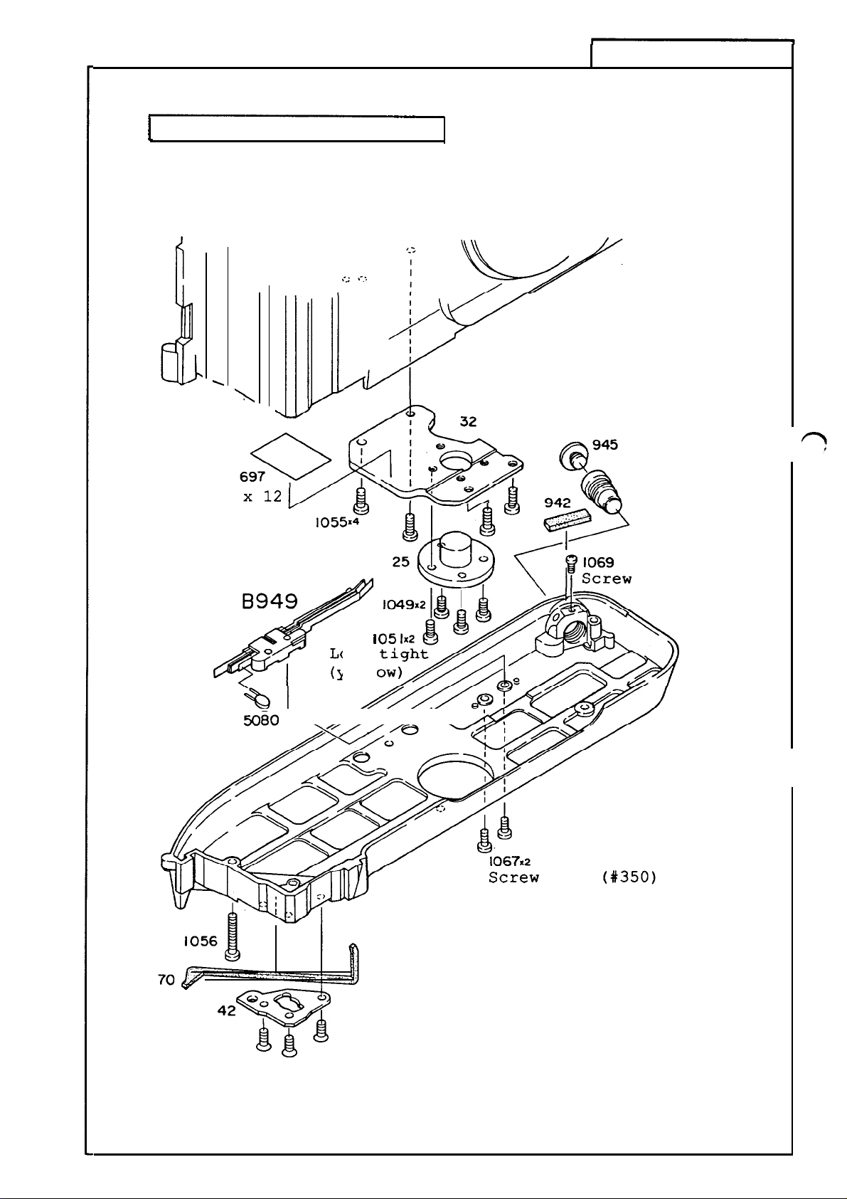
Bottom cover and tripod parts
/’”
-1
\
FAA23051
- R.3248.A
15
0
K
%1
W80
\ ////2’K
Lock
(yell
i
Screw
0935
lock (#350)
00007
n
lock
‘ ‘2%9
Lky+$
I 128x4
—A2—
Page 5
FAA23051
- R.3248.,
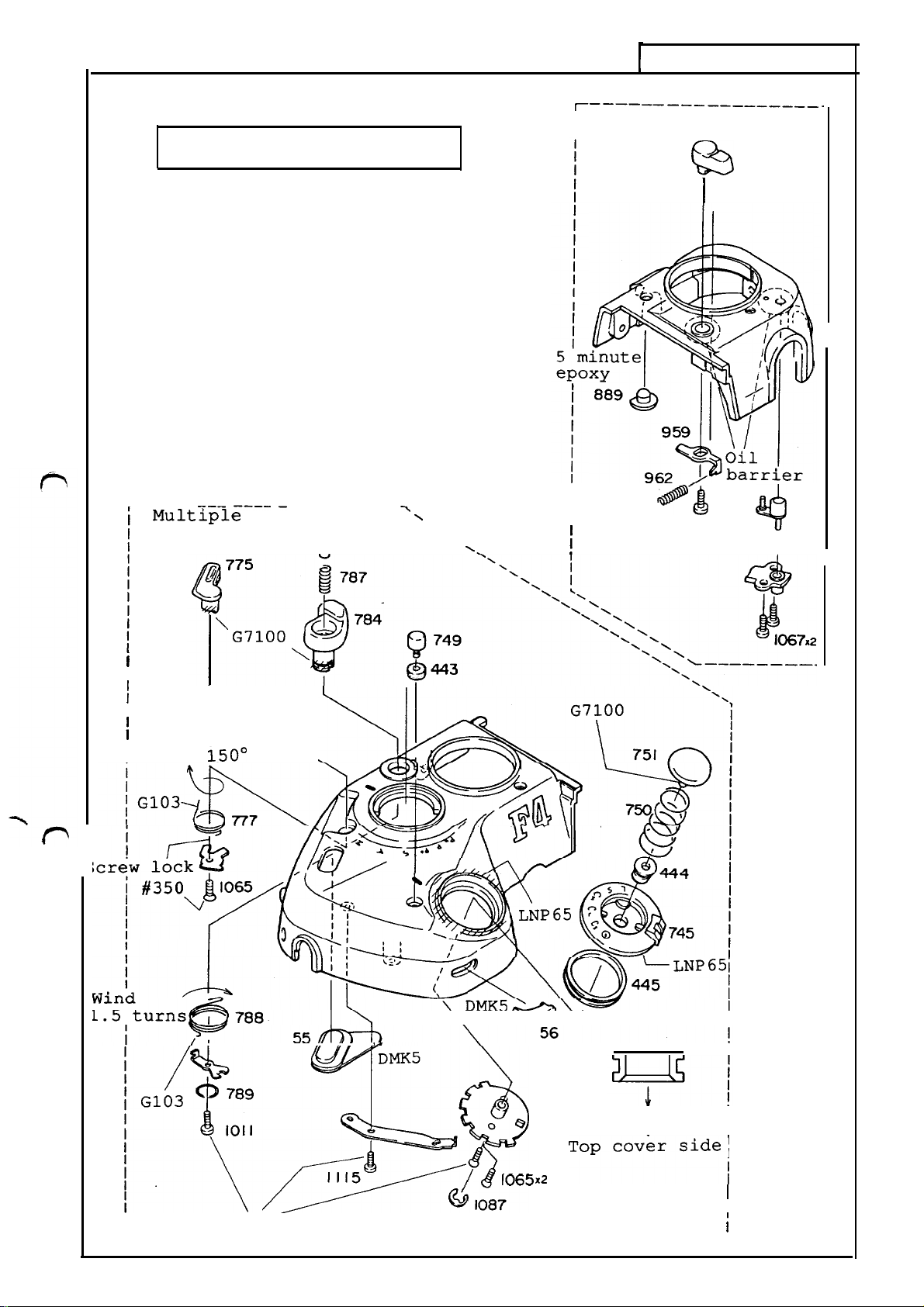
Film advance side top cover
Film rewind side top cover
.——. .—
~—— ———. —
Mult~ple
exposure
lever
— _________
786 “,
$?
~__——
I
—— — ___________
960
.
6?3
I
~
N
\
N.
i
I
~
&@&
/
I
105
4
%
i
/
/
I
I Turn
\
150°
I
--l l/
A’-----
\------w
\
v
I
I
l’~~z>$
1115
I
I
G __________________________________________________ J
Screw lock (#350)
‘A3
~
/
1087
I065xZ
—
,Opcoversidel
,
i
Page 6

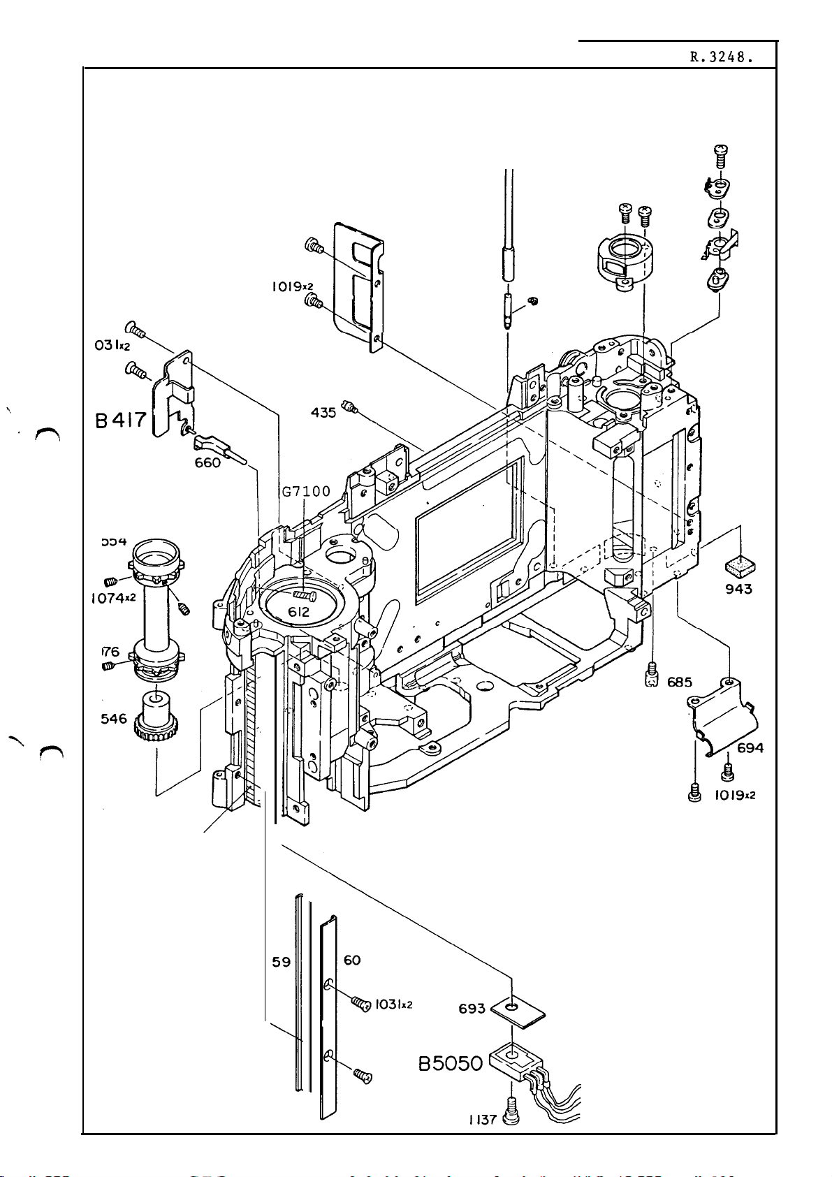
Back body parts
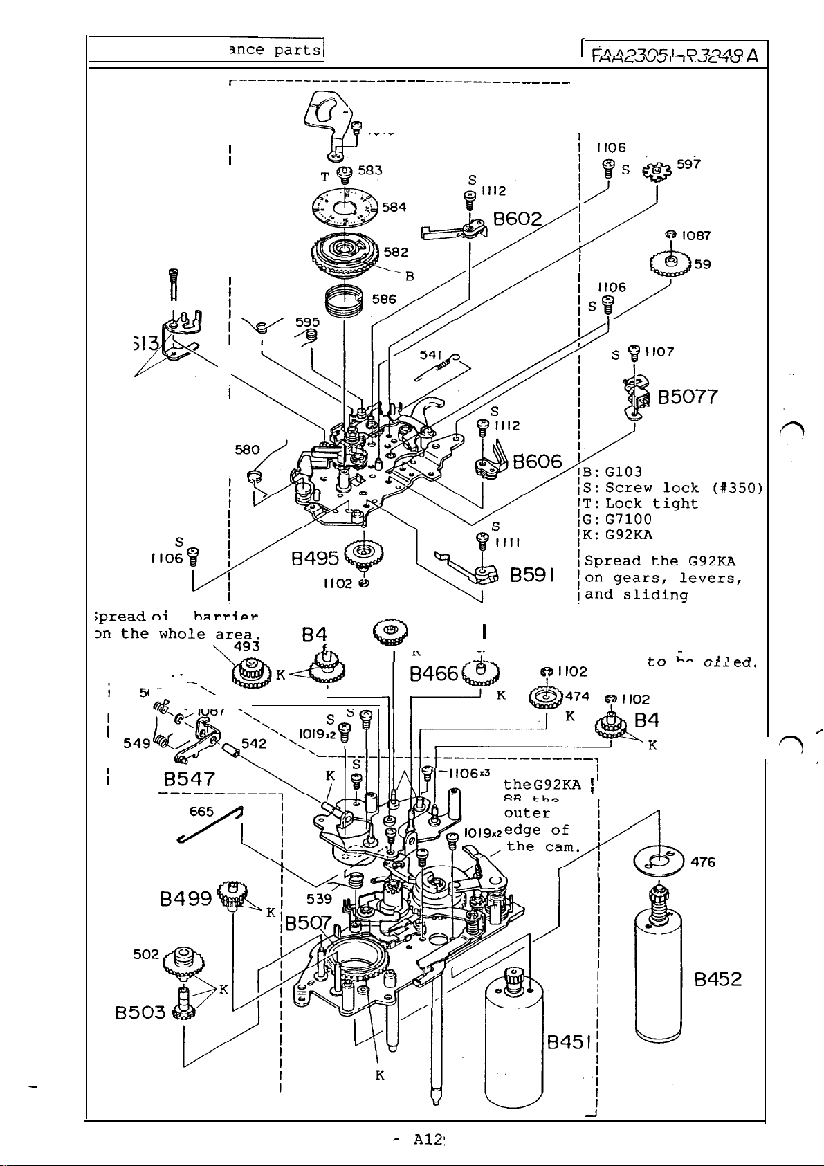
— Spread G103 on the body and paste,
—A4—
G92KA
Page 7
G71OO:
4
f)
28
FAA23051
1023
- R.3248. A
I 109
W
. 929
&
“ 930
&
\,
n
,./
I
554
m’
1074xZ
1076
@
@
433
1
29
G71OO:,
i
/*
1085
902
928
&
927
&
)
J
G103
\
59
(grey)
E
c
(white)
B
(purple)
—A5—
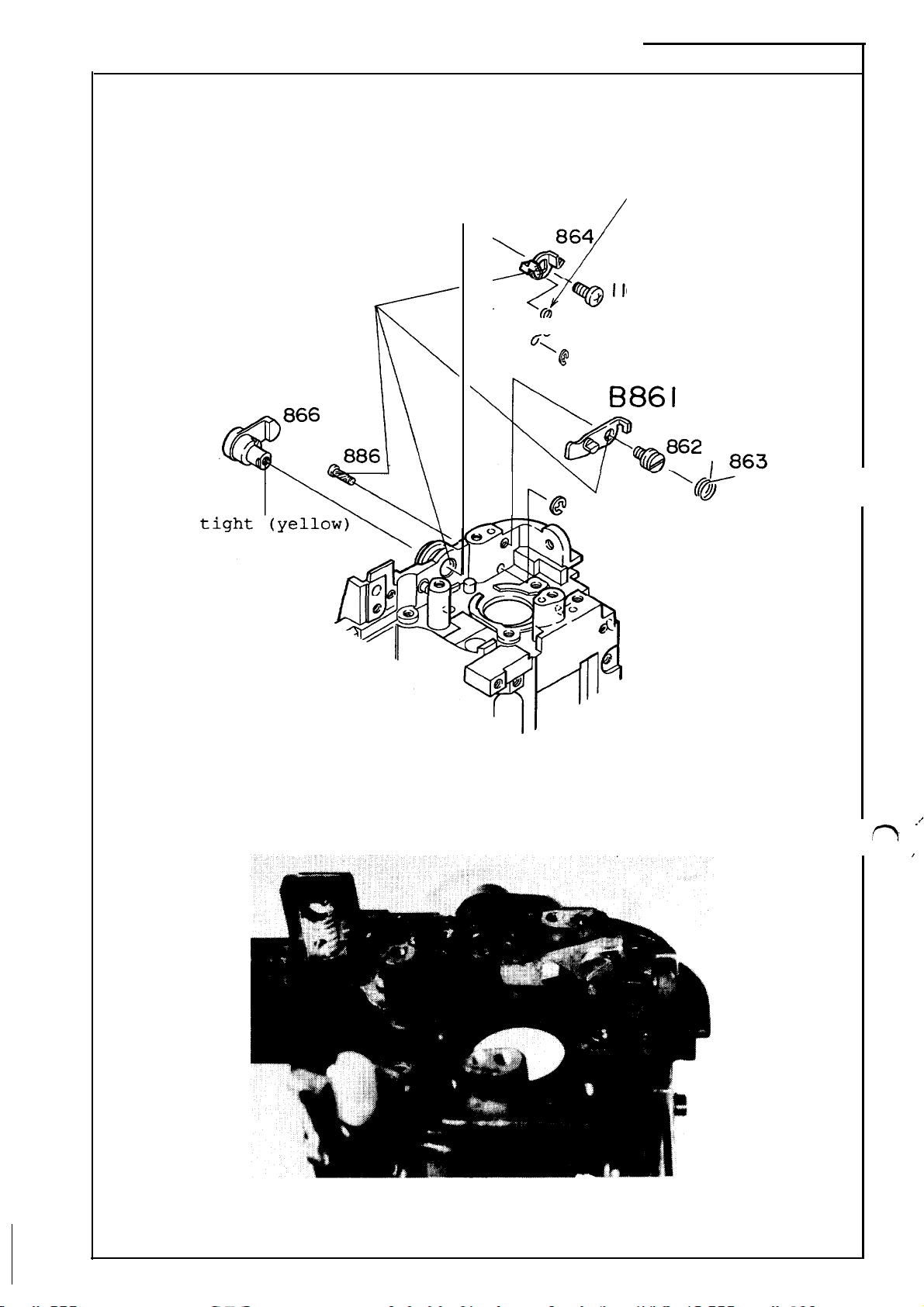
Page 8
FAA23051
Hook the spring end
(with more turns than the other end)
on the #864
- R.3248.A
864
Lock
G71OO
>
./
-&@
868
$
I 105
%
@
1087
n
p@?
v
1085
./
n
,
1
—A6—
Page 9

t
l17AA’_)2AC4
– D 90/.0
Sync contact,
film detection switch
— Sync contact
#llo9
lder this portion
(black) GND
(green) Sync contact
\
G103
n
— Film detection switch
Film detection switch
Lock
cable for base plate
g#lo40 SC;:;5;
I
Power supply base plate --
3
main FPC bottom unit
(orange) (black) L = 140mm
Power supply base plate --
+
power Tr. FPC
(orange) (black) L = llOmm
— junction cable
Film detection
switch pin
\
External film
guide rail
m
?&
/
Film detection switch (brown;
~[
PTr-E (grey)
PTr-C (purple)
PTr-B (white)
Check the ON-OFF position of the film
detection switch based on the external film
guide rail:
Height (or play); a = 1.13 f 0.15
1.00
ON–OFF switching position; b =
Total stroke;
More than 0.1 deeper from the
or more
external film guide rail.
—A7—
Page 10
FAA23051
.’
.
- R.3248.A
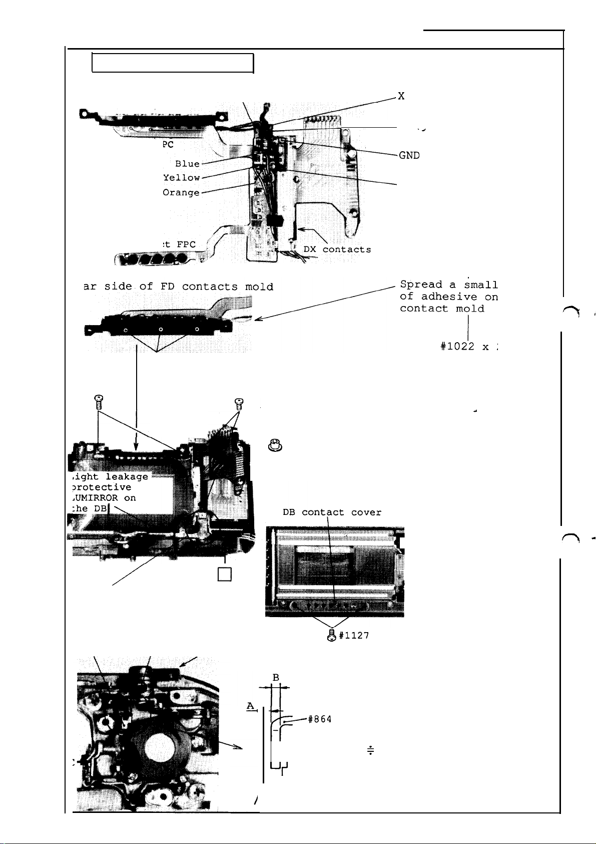
FD, DB,
Thyristor trigger base plate
FD contact FPC
DB contact FPC ‘“
{~
Lear side of FD contacts mold
*+’----+::::$’::
}1040 x 2
. .
II
or DX FPC unit
--
.,
~
i:E;2k>~
<. ~ ,’
i.
-.: ~ ‘,
,
:.+
. . . .
.
5 minute epoxy
,,
%!
fl;~
$. ,,~,
.
#lo22 x 2
\
,%;
%
‘.s:.:
l!?
“
,$ :.
$,: ?:, *2
9
%,
Kg
..’
~
rp-m
%$;<
~
F
7
DX contacts
.
~GND
, .,
,-
“.
t.
~X
(green) : from sync
contact
X (areen) : from FD
contact
(black): from sync
GND (black) : from
Mount FD, DB,
and DX FPCS
#lo22 x 2
#lo40 x 2
# 679 X 2
Place the DB contact
FPC through the hole
of the bodv
.
contact
FD
contact
““’
;
FL
1
/’”
Cable
arrangement
#869
#864
n
Tape for
arranging
cables
R2 lever
#678 X 2
&
P
DB contact cover
1~
*,. .,. .,>,.,.
. . .
~#864
P-
r
l-h
‘r’
—
#869
&
DB contact cover
I
#l127x2
I
Attach light leaka
protective plastic
sheet on the DB
..s
.
...+..:
>. . . . . .
~#1127
x2
Check the latching
condition of the R2 lever
The latching amount of the
#864 and #869 when the R2
lever is in locked state;
A + B (approx. 0.7)
Adjust by bending part C
indicated by the arrow in the
figure at left.
~
E’
i
Solder cables
Arrange cables
I
I
ge
‘—A8 —
Page 11
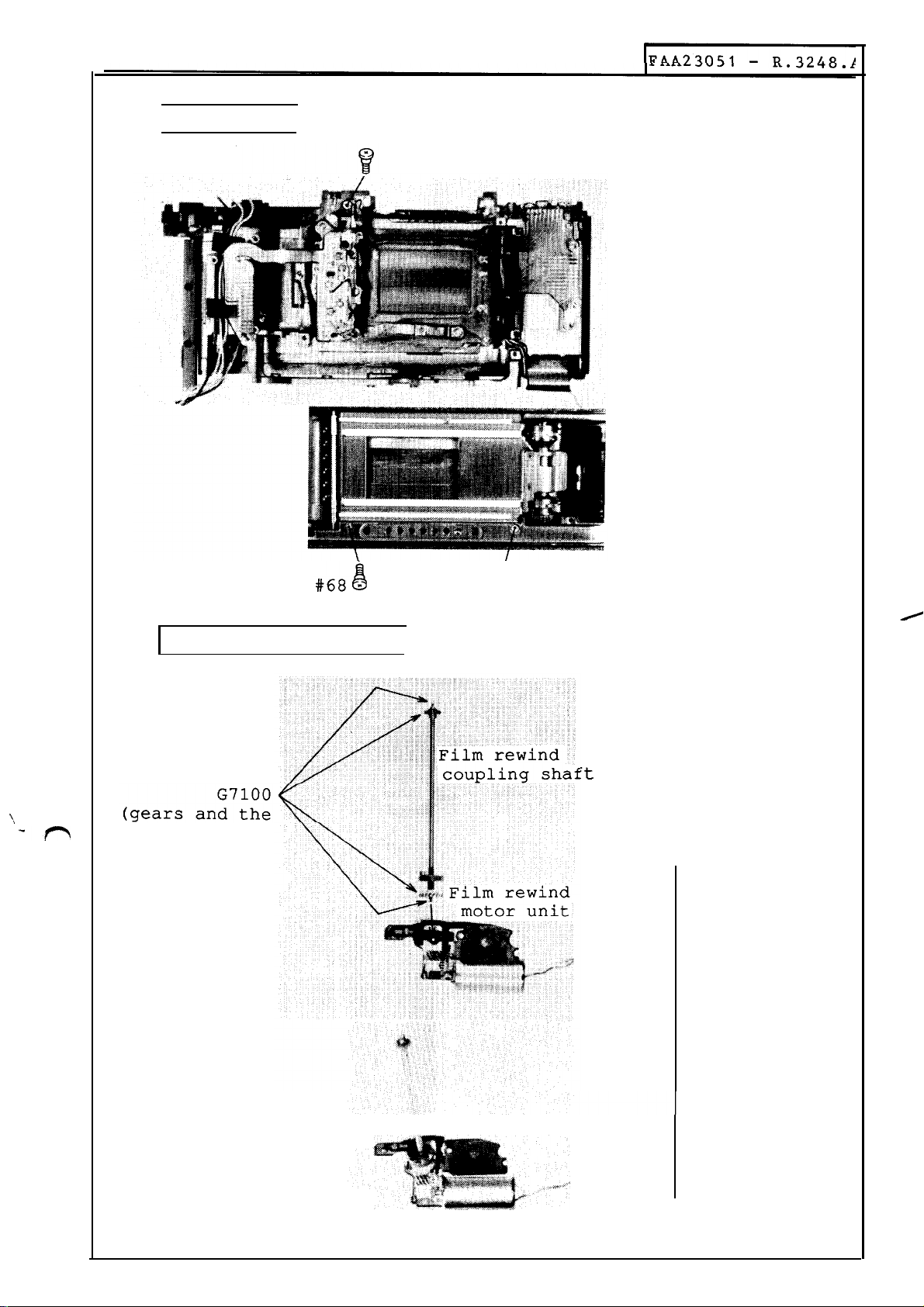
Shutter unit
1
J
#66
Shutter unit
#66
#68
#1135
\\
-?’-$
Film rewind motor unit
tips of the
shaft)
8#1135
‘t
Mount a film rewind
coupling shaft in the
film rewind motor unit.
—A9—
Page 12

Film rewind
motor unit
Au
‘&&&+. .’
Lock tight
(Purple)
. .
‘~.,~
k“
‘“ ‘“o
&
~#1019
#40
x 2
FAA23051
Mount a film rewind
motor unit
#39
#40
#lo19 x 2
- R.3248.A
Approx.
0.4
&
Check the position of
the filter selection
lever
The tip of the filter
selection lever (as
shown in the figure)
should be located
within the range of
approx.
lower end of the
shutter.
Adjust by bending the
part B as shown in the
figure .
Arrange film rewind
motor cables.
#964 X 3
0.4 from the
*
#964 X 3
—AlO—
.
Page 13
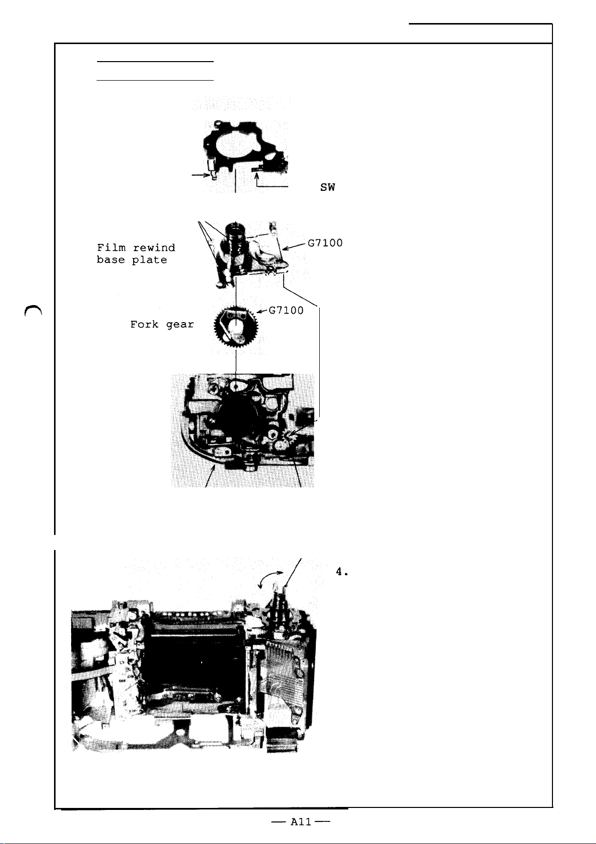
Film rewind unit
Film rewind mold
base plate
FAA23051
- R.3248.A
I-J
Camera back
switch
#1113 x 3%’
~
p
CR, ~~
I
I
Check following items:
1.
Gaps (up and down) of the
film rewind shaft;
0.1 –– 0.3
2.
ON–OFF operation of the
camera back switch.
3.
ON-OFF operation of the
R2 SW.
-m
Camera back
switch pin
Insert the film rewind
shaft from the other end.
Film rewind shaft
Lock the R2 lever (move
the lever up) . Check to
see if there is irregular
rotation and strange
sound when rotating the
film rewind shaft.
Page 14
Upper film advance parts
82563
“~
~––—–.
I
I
I
I
I
~
—_ ———. ——__— ——— — _______________
@l
1
1
I
I
I
I
I
I
I
I
614
!
u
[
j
663
;%”
86! ‘.7 , I
#
K
\
i
I
I
I
I
I
I
I
-s
W
585
t?
1010
----
[
dAA52nKi–D29ACI
[
H,J+Ldwdl
1
1
I
I
I
I
.!
1106
I
I
A-
m
Inn-r
-
Ii.dc’-tu.
J-I
t+
6
:nr@ad m+
r----
--- -------
r———-———
35
i
/
I
I
I
i
L____
1
haw~la~
. .
-
-N
\ “.
.fi --
%–-–---––––––––––----–––––––––––--J portions
69
a
\
@
B47
v
I
Igo2
except
specified portions
d
1
I
1
-— —— _____
Spread
I
the~f~KA ~
n.
~
BBO08
Pi
u-w
UC U.L.L
61
CU.
—
I
I
L—— —— — _______________________
J
Page 15
Film advance base plate
—Al 3—
1
0
2
o
IFAA23051
-
R.3248.A
)
-4
c
Page 16

Film advance base plate unit,
disassetiling, assembling
~
Disassembling
IFAA23051
- R.3248.A
Pulse blade
#1087
Pulse driving
gear
#1106
“106
Multiple
exposure
lever wire
~,;,:wd’+_:pp’eexpO
Pulse PI
(@ ~ ~ ‘“
\%
6
relay lever
shaft
‘\’
hY
t? #llo7
\l
*,
#1106
I
exposure
~
relay
.
lever
1) Upper film advance unit
(frame counter unit)
Pulse PI #1107
Pulse blade
1?
E
clip #1087
@a
not remove
driving gear)
Multiple exposure relay
lever shaft
s”rere’ay
Multiple exposure lever wire
I
pu-lse
Frame counter sw
t
I
#l106x3
2) Film take-up spool motor
(FM) #1019x2
—
)= #476
>
~Film
;
spool motor (FM)
#476
take-up
lever wire
~v
~#1019x2
—A14 —
.,
%
+
Page 17

FAA23051
3) Inside film advance unit
Ge,ar S7
Ge~r
S2
- R.3248.A
-p
~
#llo2
\,
illl@
Gear Cll
I
Gear S9
Gear S2
Gear S7
#l106x3
w
\
h
$*’
“4
k
/
~~
: %
*
~
I
Gear
Film take–up spool
clutch spring
Film take-up
clutch lever
Gear S9
Gear S1O
Cll
#lIo2
I
I
spool
#1087
I
I
\,
-n
Gear
#1087
Film take–up spool spring
Inside film advance unit
~
Film take-up
~
spool clutch lever
i
~
/.....@:
— A15—
Page 18

#1019x2
Screw lock
(#350)
I?AA23051
Lever on the
shutter release
through shaft
S
/
Gear S11
4) Shutter charge motor
(MM) #1019x2
— Assembling
(See page A12 for applying
oil and attaching)
1) Shutter charge motor
(MM)
#1019x2
- R.3248.A
Multiple
lever spring (#539)
Charge motor(MM)
Fig.
Film sprocket advance completion state.
below:
/
Film sprocket
shaft
Overcharge amount
is more than 0.2.
Film”advance
stopper
l-H-
‘ilm advance
topper click
14
Film advance
stopper
~latch lever
&xposure
(1) Portions b and c (as shown in
the figure) of the film advance
stopper will be disengaged from
the film advance stopper latch
lever when the shutter charge cam
is rotated in the direction
indicated by arrow a.
(2) Portions b and c will be
engaged when the film advance
stopper click moves toward
the portion e by rotating the
Film Sprocket shaft
the direction indicated by
arrow d (as shown in the figure) .
Check to see if the overcharged
amount of
lever and the stopper is more than
0.2 by rotating the film sprocket
shaft in the direction indicated
by arrow d. (See left figure)
-
Mount the motor by moving
aside in the direction
indicated by arrow.
Check the condition of the
Film Sprocket shaft
advance completion.
Set the Film Sprocket
shaft to the film advance
completion state
theFilm
advance stopper
Film
in
latc~
e?
Film advance stopper
Film’sprocket advance
completion lever
—A16—
Page 19

lFAA23051
1
2) Inside film advance unit
- R.3248.J
“
,,
p
Gear S11
\
Multiple exposure
lever spring (#539
.ng
latching
location (#539)
Mount this by rotating
the inside film advance
unit in the direction
indicated .by arrow b
while pulling the spring
(#539) in the direction
indicated by arrow a.
Note :
not to pinch the spring
(#539) between the lower
film advance unit and the
inside film advance unit.
Care should be taken
I
&#l106 x 3
Screw lock (#350)
3) Film take-up spool
motor (FM)
#476
#1019x2
\
{
/
‘1
/
Multiple exposure
lever wire
~#1019x2
Screw lock (#350)
—
A17—
Page 20

#llo2
9\
Dipping in oil barrier
Gear S2
.#l106x3
Gear S7
Gear
S9
4 ) Mounting gears
Gear S1O
I
Gear S9
I
Film take–up
clutch lever
spool
#1087
I
Film take–up
clutch spring
spool
~pply
oil (G92KA)
to each gear.
Dip the gear S2
in
oil barrier
*
Slo
Film take-up
spool clutch spring
View
A
Gear Cll #11
Gear C9
02
I
Gear S2
I
Gear S7
Check the film take-up
spool clutch lever
latching amount
n
—A18—
Film
cl
take-up spool
.utch lever
Gear S9
,>~
Length b should be more
than half of length a.
View A
,
Page 21

.
Frame counter
scale plate mask
Frame
scale plate
counter gear
Stopper
Shutter charge
completion sw
al
\
Screw lock
counter
G103~
/
&ll!l$
#583 ‘
*
l’”
. .
+
:$.
I
-’
#lolo
(#350)~
i
Lock tight
Frame counter
&reset
spring
lFAA23051
5) Upper film advance
unit
Frame counter reset
spring
I
Frame counter gear
Fix with a stopper after
rotation the gear two
turns in the direction
indicated by arrow a
(clockwise)
- R.3248.A
I
#583
Frame counter scale
Use G103 to stick the
projected portion of
the frame counter gear
and the caved portion of
the frame counter scale.
Frame counter scale
plate mask
,
#lolo
Cut-outW’s”
-,*.
W*,
W
““P
n
,/
/
Film advance completion switch
Adhere each screw with screw lock (#350) .
Apply oil (G92KA’
m
:..: .
1
l=+
n
Index
Frame counter
scale
I
““’
on each gear and lever.
%
b
Inspection (ON–OFF)
“ Shutter charge completion switch
● Film advance completion switch
“
Frame counter switch
Frame counter scale goes off between
frame counter O and 1 when the frame
counter gear is rotated clockwise.
● Check the location of the frame counter
scale mask
Frame counter scale is within the range of
more than 2/3 of the width of the counter
index (counter scale plate mask) . See the
figure at left.
Adjustment :
counter scale plate mask after unfastening
#lolo.
Cut-out of #576
should be faced with #577.
Adjust by moving the frame
—A19—
Page 22

6)-Mounting upper film advance unit
*Small parts (see page A14)
~wer
film advance unit assembly
lFAJk2305i
Upper film advance unit
-
~#l106x3
R.sN+&Al
Screw lock
(#350)
Fil”m rewind
coupling
slide lever
Lower film advance unit assembly
Set the film sprocket shaft and the shutter charge cam
to, the film advance completion state.
I
I
Upper film advance unit
#576
Set the cut-out of #576 to the proper place as shown in
the figure at left.
Mount the unit so that the contacts
of the film advance
completion switch comes to the location indicated by a
in the lower film advance unit assembly, and the film
%
#577
rewind coupling slide lever comes to the location
indicated by b in the lower film advance unit assembly.
(See above figure)
#l106x3
I
—A20—
Page 23

FAA23051
On–off inspection of film advance completion switch
Film sprocket shaft is in the film advance completion state.
k
- R.3248.A
B51
Film sprocket sha’ft
Ipper
film
.dvance plate
‘ilm advance
!ompletion
witch #602
Thermal contraction tube
lpper film
Ldvance
plate
B531
#603
(#564)
I
Fi’lm advance
Film advance stopper
(B531)
/
c,
/
Film sprocket
advance completion
lever (B533)
1
B533
ilm advance
Film sprocket advance
completion lever (B533)
stopper
(l
Film advance completion
I
switch is off in
film sprocket shaft
advance completion state.
{L)
The gap between the lower
part of the thermal
contraction tube (#564)
and the upper side of
#B531 and #B533 is more
than 0.2 when rotating
the film sprocket shaft
while depressing #B519 in
the direction indicated
by arrow a.
St
.oppe
r (B531)
-
the
(3
Depress #519 in the
-More than 0.2
II
#602
#603
$4iii==0”2
#602
*
~
#603
~B531
B533
direction indicated by
arrow a while film
sprocket shaft is in film
advance completion state.
(Set to the film advance
stopper release state.)
Make sure that film
advance completion switch
goes on by #B531 and
the gap between the
thermal contraction tube
(#564) and #602 is more
than 0,2.
(4)
Rotate the film sprocket
shaft in the above state.
Make sure that the film
advance completion switch
goes on by B533
instead of #531. And the
gap between the thermal
contraction tube (#564)
and #602 is more than
0.2.
—A21—
Page 24

Mounting film advance base plate unit
“
FAA23051
- R.3248.A
~utter
?ve
r
Figure below:
Shutter charge cam
charge
\
Film advance completion
Lever on shutter relase
through
haft
Shutter charge
completion switch
(grey)
(white)
Film advance
completion switch
state
.,
E (blue)
I
P
K (green)
+ 3.3V
(Pink)
‘n
;hutter charge:
Iotor
(MM)
g
1+
R
,’-”
AWIW&
~Film
spool
/“
r
,. .,-
//”
/
take–up spool spring as
ar S11
take-up
spool
motor (FM)
.
//”
“P
1) Mounting film take-up
spool
Install a film take–up
spool after mounting a f
shown in the figure.
Film take-up
spool spring
a
/“
‘. . .
-
. J
—
Film take-up
spool
17
i lm
0,
Page 25

Film advance base plate
positioning pin
G71OO
FAA23051
Z)Latched portion
of film advance base
plate and shutter.
“:
Indicating
latched portion
- R.3248.
-r
N
:amera
:losing coupling pin
back opening/
#1049x2
\
Shutter
T lever
Shutter
release
lever
3)
(1)
(2)
How to install film
advance base plate unit.
Reset the shutter Mg set
lever by depressing the
lever on the shutter
release through shaft
after setting to the film
advance completion state
by rotating the shutter
charge cam
counterclockwise .
Set to the film sprocket
shaft advance completion
state by rotating the
film sprocket shaft
counterclockwise .
Resetting method
Reset the shutter Mg
set lever by
depressing the lever
on the shutter
release through
shaft (see page A22)
while settinq it to
the film
completion state by
rotating the shutter
charge cam
counterclockwise .
I
adv~nce
:ft
side
film sprocket
:rew
(#1074)
Pull the EL roller forward
mount a film take-up spool
on the film advance base plate unit.
and
—A23 —
Mount the film advance
(3)
ba:
e Plate
EL
roller forward.
Note:
“
Film advance base plate
should be surely fixed
in the film advance base
plate positioning pin.
● Film advance base plate
and shutter are surely
latched.
“
Film take-up spool
motor (FM) cables should
not be pinched.
by
pulling the
Page 26

I
(4) (See page A21)
Mount film advance base plate
mounting screws (#1049x2
#774) after resetting the film
advance stopper by depressing
B519 in the direction
indicated by arrow a.
Temporarily fasten the film
sprocket screw (#1074xl)
(the left side sprocket screw)
Inspection
- R.3248.A
r
a.
b.
Shutter charge
Rotate the shutter charge
cam counterclockwise.
Shutter
Depress
shutter
shaft
l-~ &..-...-
LL LULIIS
release
the lever on the
release through
to T (time)
I
Reset the T by moving the
T lever in film rewind
direction.
(5) Cable arrangement
(a:
Junction cables)
Adhesive
arranging
t
:ape
for
cables
,
I
Power supply base plate
–– main FPC bottom unit
(orange)(black) L =
—
Power supply base plate
–– power Tr. FPC
(orange)(black)L = llOmm
PTr-E (grey)
PTr-C (white)
PTr-B (purple)
140r
T?
n
!/
PTr (3V)
lo~—(yellow)
Film rewind motor (RM)
(pink) (blue)
—A24—
@
G103
Shutter charge motor
F~lm detection switch (brown
,black)
Film film–take-up
SDOO1
motor (FM)
{red) (black)
(MM)
Page 27

Shutter release Mg,
Lever under shutter release through shaft
Shutter release
throuqh shaft
K
@llol
d
616
Shutter release Mg
FAA23051 - R.3248.,
B453 “
#G2KA
;ever under
shutter rele
through shaf
and its bear
(release Mg)
Shutter
&
~
<2
i
%!
‘1
~
—.
00
o
1052
hQ
i.”
@
615
“a
~
1090
““
1052
_ lever under shutter
release through shaft
/
Inspection
a. Thrut play of shutter
release through shaft:
0.1 -- 0.3
b. charge amount of the
lever under the shutter
release through shaft:
More than 0.2
Check the charge amount
by rotating the shutter
charge cam
counterclockwise.
““ Adhesive tape
for arranging cables
Spring latching
lL&ver under shutter
I
#616
release throuqh shaft
— A25—
Page 28

DC-DC converter base plate
GND (
Vccl
+5 . 5V
l?AA23051
- R.3248.A
+12V
CONTR
*Be
sure not to pinch cables.
!Power
Tr FPC
unitl
Q
#685 X
Q
#lo19
2
—A26—
Page 29

Shutter speed dial base plate
i
FAA23051
1)
T (time) lever
RI set lever
Latched position
- R.3248.A
r
Insulating tape
: ,,
\
\
106
.1
.catec
by a in the figure.
● RI set lever
See the portion indicatec
by b in the figure.
R1 set lever on the film
advance base plate
(uppe;
film advance unit-) and R
sw lever on the shutter speed
dial base plate should
bf
latched.
2) Mounting shutter speed
dial base plate
\
.
1-
Adhesive tape
Solder
(frame counter switch)
3) Soldering cables
I
#lo50
#lo54
#1106
B
A#A ~.
Shutter charge
~completion
b
~Pulse
PI (pink)
switch (grey)
<Film advance
-
completion switch (white)
\
\
\
‘k
‘\
‘se’PI (blue)
b
— A27—
Page 30

FAA23051
,/’
/
- R.3248.A
amounting
a
Main
FPCI
Shutter release tool
T
Refer to pages D1O to
Dll when mounting main
FPC .
a.
Insulating tape
b.
Adhesive tape for
arranging cables.
Adhere cables on the
rear side of the
main FPC.
#&.
I
F
4
?—Press contact
I
.
—.
Checking camera back
(Refer to above figures)
,SC base plate
5.W
c1
+–
-D
#672
#B670
#1023x2
1
Vcc
L = 105mm
(n:
— A28—
(grey)
junction ca
1)
shown in
figure.
2)
advance side press
contact.
3)
power supply base plate.
4)
tool (self–made tool)
I
,ble)
Set the
Press contact the film
Supply 5.5V power to the
Mount a shutter release
SC base plate as
the above
./
Page 31

lFAA23051
‘“,
/
- R.3248.1
r
Note :
A. Check the back body (as shown on page A28) .
B. Personal computer and back body inspection
Set the shutter speed dial to 1/4000 sec. or
slower until AE adjustment is completed.
“
Set the exposure selector mode to M
● Turn off the camera back switch (push the camera back
switch pin)
(1) Shutter release
(2) Shutter speed
(3) Mechanical shutter charge sequence
(4) S-C mode (L,
(Hook up personal computer and communication tool
[J15279])
(1) Inspection of operation
Film take-up spool
Film rewind motor
Shutter release
Mechanical shutter
(2) Inspection of switches
(3) Inspection of dials
(4) Inspection of LCD display
S, CH, CL, Cs,
Self–timer)
motor
charge sequence
-f’-
\
‘\
—A28-l—
Page 32

Front body parts
Lens release
,019.FC:F.
I
1138 T
IO18X2
m
lFAA23051
- R.3248.
J
?’
172
B161
1034
%
lo19@a@
/
\s
@@
s
k
196
o
J
199B
\
199A
\
T
@@
0,
353 ‘
G
19
@
354
I
%
s
EE recognition switch
5
/-’
/
1072
B43
I 057
Oil barrier
G103
Screw lock (#350)
Lock tight
;:
G71OO
::
G92KA
:: LEN317A
%’
T
B46
~————___
I
,
I
/
I
I
/
“+
I
I—_
—— ——__
—A29—
-1
Double lock knob
\
0--’
1
\
9$
v)
o
AF lock button
t-
Page 33

/’
FAA23051
-
R.3248.i
r+
B688
@
a
0
0
@’
695
.
98mm ,
//AF lens contact
/
-
B
FPC
22
—A30 —
Page 34

EE recognition switch (orange)
I
FAA23051
- R.3248. A
Insulating tape
1)
Checking double lock switch
The switch turns on when the double lock knob is set
to the double lock side.
Double lock . . . .
2)
Checking EE recognition switch
The switch turns off at the height of 0.3 to 0.85mm
from the bayonet ring surface.
Aperture coupling ring
AF PTr-E (orange)
AF PTr-C (white)
AF PTr-B (purple)
.
\*.~
(~
--
owe
ase
+
b
P
Tr
latg
‘n
EE recognition pin
//////////1
Bayonet ring
— A31
i
I
—
0.3 to 0.85mm
Page 35

AF base plate unit, fo base plate unit
AF motor
B313
lFAA23051
- R.3248.A
fo base plate .
s:
Screw lock (#350)
K: G92KA
I
b’:
fo lever
AF coupling
ever hole
Spread L21
on each sh
13
aft .
5075
\
~
AF.PI
— .
Checking fo base plate
Adjustment of btush position on
fo base plate
. . . . . . .
.
‘b:
.:?!
.< 1
!
_
*C
brush positioning
1~
I
{
AF
coupling
ring lever
: Note:
Do not bend
I
II
1.24~0.2
Mount the fo lever on the
base plate unit,
Mount the AF base plate unit
on the front body by adjusting
levers and pin indicated by
arrows in
b–b’:
~–cl:
Hook the AF lever spring
(#410) on
There should be a
contact portion
and end of fo pattern when lens
attached.
the figures:
fo lever
AF coupling lever
AF base plate
positioning pin
#1048x2
the hook.
space between
Al
brush
is not
— A32 —
Page 36

I
i
I
I
/
/
:
I
I
I
I
I
i
i
L––_–––_–_– _______
Z7A--+j/
/
KE347B
.A
—
990 ,
6
N
@’ e
T~
[015
1032
B 207 I
——— — — _________ ,
I base plate unit
r
.1.
11085
I
I
1085G~
/’
I
I
J
9
i 44
149
\
\
:4
i
I
I
I
Lti
__________
‘“’”
‘
---------------
i
S:
:
G:
T: LOckt’ght
I
I
i .\\
Screw lock (#350)
G7100°
Filter driving
base plate unit
]
-1
I
3
1012
I
1
L
—————_————— ._——_—____ _ _______.___l
tr-
Sprea’d L2113 on each gear shaft
— A33 —
1
I050X2
I
I
Page 37

Mirror box unit
L
base plate unit
fmm
sl
~itch
TC switch
(white)
(brown)
L_”l._J
lFAA23051
fmm base plate
I
.-
~
- R.3248.A
Mirror
Sub-mir
‘stopper
fmm signal
i
I
base plate
lever
G8181
Ma
in mirror brake
coupling lever
,Sub-mir
stopper
Shutter
{
~own
ror
spring
ror
lever
charae
spring
lever
.-
Mirror up stopper
G71OO
Aperture lever
“Aperture photointerruptor
(with positioning pin,
attach with adhesive like Alon
up sprin
re lever
spring
re lever
re Mg
lever
Al fa )
—A34—
Page 38

lWAA92n<l
- D ‘1’_)/,
Q
I
— Aperture Mg
Aperture Mg click — Adjust the gap between the
click and the ratchet gear.
Shutter charge lever
(See page D23)
I
n
0.2 to 0.3
f~y
;L
u
,/
Aperture driving lever
-
-1
—
Ratchet
gear (#81)
crew lock (#350)
\
#lo12
resetl
#149
I
,atchet
reset gear (#81)
Aperture Mg
Push the shutter charge
lever in the direction
indicated by an arrow b
to be shutter charged
I
I
I
state.
Mount on the I base
plate by hooking #149 in
the hole of #81.
(Arrow a indicates the
hooking position on
which one end of the
spring (#149) is hooked)
I
#lo5
erture PI
Spread KE347w
—A35 —
I
Mount #105 by rotating
#81 around 270°
clockwise .
#lo12
Page 39

FAA23051 - R.3248.
IMountin
g mirror unit, I base plate,
See page
Mounting mirror box, front body
See page
Adjust thrust play of
Rated value: O
Adjustment washer
L base
D23
D22
1K050-334
1K050-335
1K050-336
platel
-
.1 ~o 0.3
0.1
0.05
0.15
mirror
I
unit
Cable arrangement
:ab
le,
FPC, adhesive tape
foz
. cable arrangement
AF lens contact FPC
TC switch (white)
fmm switch (brown)
EE switch (orange)
1K050-337
1K050-338
‘J
0.2
0.3
,
FPC positioning pin
~
\
y
~
!4
—A36—
Page 40

AA23051
-*
R.3248.
A
Filter driving base plate, filter unit, TTL SPD
See
pages D20 to D21
— Filter unit
Check:
Filter mirror holder moves by its own weight
when the front body is declined after
assembly.
— Filter driving base plate unit
Check:
Check to see if the filters are switchable
after assembly.
See
page D19.
AF mode selector lever unit
unitl
,nl
lLens
Check AF switch 1, AF switch
Check continuity of each switch
AF switch 1 (blue), and GND and
tester.
;
mode
;
mode
d
mode I
(2)
See
page D19.
release button
switchl
See
page D18.
2,
lens release button switch
by”connecting GND (body) and
AF switch 2 (white) using a
(1) AF switch inspection
AF switch 1 (blue) AF switch (white)
I
off
on
off
I
on
off
off
Lens release button switch inspection
AF switch 1 and AF switch 2 turn off when the lens
release pin is within the range of 0.45 to 0.85 from
the bayonet ring.
~—c
,––__
I
~
~_
Al? SW
Release SW
“1
c1
j
AF SW2 (white)
~AF
_>_M_
J
GND(body)
SWI
(blue)
Bayonet
— A37 —
Page 41

Mirror operation base plate unit
See page D17.
Check preview bottom and mirror up operations
f–fo base plate, f–fo pulley
)
FAA23051 - R.3248.,
— f–fo base plate
— f–fo pulley
f–fo pulley stopper
See page D18.
Mount by rotating the
pulley once clockwise
while aligning the f–fo
pulley spring (#402) with
the f–fo pulley shaft
groove .
#1087
Note :
the plastic mold
shaft of the f–fo
pulley.
Reel aperture
coupling ring thread
in the #403 groove.
(See figure a)
Do not damage
Aperture co
I
ring thread
*
— A38—
087
Note :
(1) Thread knot
should not be pushed
out from the surface
of the f–fo base
plate.
(2) Aperture
coupling ring thread
should be hooked in
the roller on the AF
mode selector base
plate.
(3) Aperture
coupling ring thread
should not be bent.
.
a
Page 42

1) Adjustment of f–fo pulley stop position
Aperture coupling ring is attached to the stopper.
/
2) Adjustment of the f–fo base plate position.
~–fo
base plate
\
The f–fo pulley
is being attached
to the stopper.
Use adhesive
(Alon Alfa) to-
attach.
c-
#403
Adjust by rotating #403 so that the aperture coupling
ring and the f–fo pulley come into contact with the
stopper simultaneously.
Screw lock
(1)
(2)
10X2
(3)
Mount the f–fo tool lens
(J18202)
Set the digital voltmeter (at
the resistance measuring
range) as shown in Fig. a.
Adjust by rotating the f-fo
base plate so that each
resistance value can be
measured when the f–fo tool
lens (J18202) is moved aside
as shown in Fig. b.
on the body.
\f
[
Q
&
v
>,
W
$
\
o
.
+
]urple)
ig
a-
.
J
‘iq.
(yellow)
Resistance value is 624 to
936f2
moved in the direction
indicated by arrow c.
Resistance value is OQ when
moved in the direction
indicated by arrow d.
(4)
—A39—
Fasten screws (#1010x2) and
spread screw lock (#350) on
them.
when the tool lens
is
Page 43

\
— Soldering cables
- R.3248.A
Solder
plate.
f–fo base plate
Vref
(purple)
AGND (blue) and Vref (purple) on the f–fo
F’-
+
70
AGND (blue)
base p
late
base
— When f–fo pulley shaft is damaged.
(1)
(2
(3
(4
Remove the f–fo pulley and the f–fo base plate.
Remove the damaged f–fo pulley shaft.
Note:Check to see if there are any broken
pieces left in the L base plate.
Mount the f–fo pulley shaft (1K371-359) .
Spread adhesive (Alon Alfa) at the portion where
the f–fo pulley shaft is mounted.
‘A40
—
Page 44

lFAA23051
- R.3248.A
Lock encoder FPC unit
See page D17.
Cable arrangement on the lower part of the L base plate
Hook AF motor cables on the holder.
--’4
,
[se
adhesive
:103)
to atta
ref (purple) ,
-fo (yellow)
SND
(blue).
~F
switch 1 (blue) _/’
w
switch 2 (white)
AF motor (red),
Vref (purple)
AGND (blue)
(black)
IAF
base plate unit
See pages D15 to D16.
—
A41—
Page 45

I
FAA
230 51
-
R.3248.
I
lPositioning
fmm base plate
rC
switch
white)
(
Emm
lbrown)
I
H-
o
w
adjustment of fmm
Screw lock
(#350)
\
\/l
o
fmm signal lever
#1037x2
switchl
(1) Connect a tester between
the TC switch (white) and
the body (GND) .
(2) Mount the 50mm (f/1.4) AI
lens on the body. Do not
move
the protection ring of
the 50mm f/1.4 AI lens
(indicated by arrow a)
pushes the fmm signal
lever.
(3) Fasten the fmm base plate
at the point when
switch is changed from ON
to OFF by moving the fmm
base plate.
signal lever brush should
be positioned at the
center of the TC switch
and the fmm switch
patterns.
any further once
th=
TC
Then the fmm
I
Protection ring
\
(4
Noi_e :
a
The fmm switch should be
off when the 50mm f/1.4
AI lens is removed.
Correct lens:
50mm f/1.4 AI
(Do not use 50mm
AI-S and AF 50mm f/1.4.)
f/1.4
—A42—
Page 46

Height adjustment of aperture lever
IFAA23051
- R.3248.,
Rated
value :
n
Eccentric
adjusting
lever
screw for
aperture
Screw lock
(#350)
o
Aperture lever
Height adjustment of AF coupling ring shaft
Adjust the height by turning the screw (#1078) so that the
&
AF coupling shaft is higher by 1.6
surface when the lens release button is free in AF-C or AF–S
mode .
0.1 than the bayonet
-’l
Lens release pin
Lens relea
button
se
Bayonet surface
u
w
#1~78
Screw lock
i
Q
AF coupling
ring shaft
3
o
.
—A43—
Page 47

L....-<”
1
<,
. ..4-T”.
Angle adjustment (45°) of main mirror (Gl), sub–mirror (G2)
— Angle adjustment (45°) of main mirror (Gl)
Tool: . J18037 (Optical flat)
Screw lock (#350)
1037x2
● J18038
● Vertical collimator
● Hex key
Rated value:
Horizontal discrepancy;
()+18 g
B204
Adjustment of hor
i
.zontal
Vertical discrepancy;
+0 )
o
–lo ‘
discrepancy
&
,
Adjust
by moving
B204 vertically.
#239
Adjustment
Adjust
vertical discrepancy
of
by
rotating #239.
— Angle ad-justment (45°) of sub-mirror (G2)
To01:oJ18196
(determines the
angle (45°) of the subrnirror)
●
Vertical collimator
Rated value:
Vertical discrepancy;
5*5’
#253
+
o
@
%
n
f–fo pulley
T
Sub-mirror stopper lever
Adjustment of vertical discrepancy
~
o
Adjust by rotating #253.
— A44—
Page 48

- R.3248.A
lMounting
— Preparation for mounting on front body side
~ilter
d
oupling
.riv
le’
on front body and back
bodyl
Shutter
Start 1
cha~
ever
“ge
lever
1)
2)
Move the mirror down
Move aside the filter driving coupling lever to film
Note :
● Move the mirror down
lever to the bayonet
“
Spread G71OO on the tip of the shutter charge
by pressing the shutter charge
ring.
lever, and start lever.
rewind side or in the direction indicated by arrow a.
Eliminate foreign matter in the filter and AF sensor
units by using a blower.
‘A45
—
?,
Page 49

— Preparation for mounting on back of body
- R.3248.,
1)
The body should be set in the film advance completion
state.
Shutter charge lever
/
Shutter release lever
Shutter release
levez
should be set to the
back position.
‘Mirror down lever
Note:
Check that the T (time) lever is correctly
latched.
(See page A27)
far
2)
3)
Set the shutter speed dial to the T (time) position,
Move the filter driving coupling lever to the film
rewind side.
/
Filter driving lever
* Set the clutch pin at this position and fix the
filter driving coupling lever.
0
Film rewind side
Clutch pin
—A46—
Page 50

— Mounting
FAA23051
Back of body
-
R.3248.A
of body
Assembling: See pages D3 to D5.
—A47
—
Page 51

FAA23051
Adjustment of film sprocket cogwheel positioning
- R.3248.}
1)
2)
3)
4)
Set the body to the film advance completion state.
Unfasten the film sprocket screw (#1074xl) .
Set the film sprocket cogwheel positioning tool
(J18064-1) on the aperture surface.
Fasten the film sprocket screw (#1074) temporarily
after aligning the right end of the film sprocket
cogwheel to the position 31.8.
Ad-just it further so
that the right end of the film sprocket cogwheel will
+
be within the range of 31.8
0.2 when moving the film
sprocket in the direction indicated by arrow a.
I>Lock tight (purple)
\
#lo74
Reference length:
#
t-
32.4
5)
Mount the film sprocket screw (#1074) with lock tight
1111I4J-
I
a
0.4’
I
(purple) in the left film sprocket screw hole
(indicated by arrow b).
6)
Check to see the film sprocket cogwheel position by
repeating film advance operation several times.
—A48—
Page 52

Adjustment of body back
Same as for F3 and other models.
Adjustment of infini,ty
Same as for F3 and other models.
IFAA23051
R.3248.A
-
E, AF Accuracy,
inspection, and adjustment
AE accuracy inspection and adjustment items (followina
instructions by personal computer)
1. AE accuracy inspection, adjustment
I
f
Sub–menu
1. F4 + AMP.FD
Inspection, adjustment items
I
~Spot
~AMP
exposure metering ad-justment->
exposure metering
I
2. F4
3. AMP.FD
4. F4 +
Action
FD
5.
Action FD
(1) —> Adjust M 1/8000 (M 1/4000)
~Spot
I
lAMP
~
I
I
lSpot
lCenter-weighted
I
I
exposure metering adjustment—>(l)
exposure metering adjustment
(adjust by mounting on the tool body)
exposure metering —>
exposure metering—>(1)
:Center-weighted exposure metering
~
(adjust by mounting on the tool body)
—> TTL adjustment
>(1)
(Adjust by mounting
AMP.FD or
Action
FD )
.
-’l
2) When main FPC on the F4 body or EEPROM is replaced:
1) Make following adjustment (write AF compensation
value into EEPROM) after the inspection of item 1.
—> X BER P adjustment —> AZ adjustment —> Hard AGC
adjustment
—A49
—
Page 53

lFAA23051
-
R.3248.4
— AF accuracy inspection,
instructions by personal computer)
Note :
1) When making adjustment of AF accuracy, remove bottom
cover,
#1026, #1038) (see page D6), and set up the bottom FPC unit.
2) When making adjustment,
shutter or cover the body with black cloth.
3) When viewfinder is not attached,
aligning the AF inspection chart and target zone on the
focusing screen.
4) It is not required to attach AF sensor adjustment screws
(x 3) with screw lock.
1) AF accuracy
inspection
(adjustment when
disassembling AF
sensor unit)
tripod socket (see page D2), bottom FPC screw (#685,
2) AF Sensor
(when displacing)
adjustment items (following
close the viewfinder eyepiece
adjust
the AZ by
3) Main FPC of F’4
body (when
displacing main FPC
or EEPROM)
X BER P
inspection and
adjustment
I
YAW inspection
and adjustment
I
PITCH inspection
and adjustment
I
AZ inspection
and adjustment
X BER P After AE adjustment,
adjutment
djustment
YAW
write following
compensation value
into EEPROM
I
PITCH adjustment
I
AZ adjustment
I
Hard AGC Hard AGC
adjustment
X BER P adjustment
I
AZ adjustment
I
adjustment
— A50—
 Loading...