

Page 1
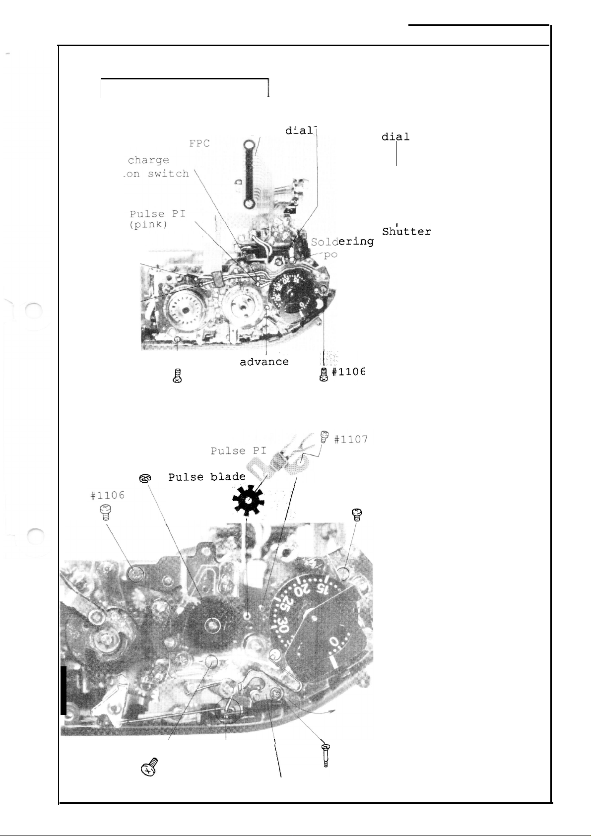
Upper film advance unit
— Shutter speed dial
base plate
Shutter
completi
(grey)
Shutter speed
w
diall
.
#lo50
FAA23051
- R.3248. A
Press contact
(See page D6)
Remove shutter speed
dial FPC
Remove cables and
soldered portion
(See figure at left)
Pulse PI
(blue)
Pulse PI
(green)
Film adv;nce
I
#lo54
completion switch
&
— Film rewind base plate
(frame counter unit)
#1087
pulse blade
@
lering
rtion
Sh~tter
base plate
#lo50
speed dial
#lo54
#1106
~#1106
(white)
Pulse PI #1107
Pulse blade
I
E ring (#1087)
I
Remove multiple
exposure lever wires
#1106
*/
$?
I
Multiple exposure
relay lever shaft
I
Upper film advance
unit base plate
#1106
I
X 3
Remove the film
advance unit base
plate by moving the
multiple
exposure
relay lever shaft ir
the direction as
indicated by an
arrow.
#1106 \’
+
8
Multip’le
exposure
lever wires
\
\
Multiple exposure
\v
relay lever shaft
Multiple exposure
relay lever
—D7
—
Page 2

FAA23051
- R.3248.A
Insu
— Film advance base
#lo74 x 2
w~gj$
J
k
Film advance
mode base
~late
.
, .,.,
~ ;J
,
,
:
\
i
~late
*Release shutter before
disassembling the film
advance base plate (Refer
to page D6)
Unfasten film sprocket
screws
#lo74 x 2
I
Power supply base plate
rnOUnting
Bottom body FPC mounting
screw
Remove
(See t]
black)
(red)
screw #1021
#1026
cables
ne
figure at left)
#lo
#1026
.
8
[echanical
harqe
motor
O
Bottom
L
l—=\
(grey)
‘ (brown
(orange
.
(yello
-
‘
\
body FPC
#lo19
Lever under the shutter
release through shaft
#lo19
@
)
)
w)
Lever under the shutter
release through shaft
:k!!g&%-
;pool
[FM)
motor
Power Tr. FPC
—D8—
Page 3

#774
rl
FAA23051
Remove cables
(See the figure at
left)
-
R.3248.l
I
Film advance base
plate mounting screw
#774, #lo49 x 2
a+
‘ n,
B519
II
o~
Uh.9fd
<~w”ue
-direction indicated
(a) to move back the lever.
Then you can remove the screw.
#lo44
I
As shown in the figure
at left,
unfasten the screw (#1049)
‘0 ‘he —
the lever (# B519) in the
A
“’=.&J#104,
if you can not
lever/
by the arrow
DC-DC converter
push
Remove the film advance
side main FPC as shown in
the figure below.
Power Tr.
#lo44 x 2
Move aside the power Tr.
FPC in the direction of
arrow b.
DC”–DC converter base
plate
#685 X 2, #1019
Film advance base plate
unit
Peel adhesive of cables
for shutter charge (MM)
motor.
FPC
unit
—D9—
Set up the film advance
base plate in the
direction indicated by
the arrow (c) .
Page 4

.
FAA23051
R.3248.~
-
(3)
*:
Main FPC
(0: junction cable)
(2) Power supply
base plate unit
VBAT
GND
(7) Bottom body film advance side FPC
PTr-
PTr-C
PTr-B
x
-%
x
%)
#lllo
Film detection
switch (brown)
GND (black)
X2
—Dlo —
VBAT (orange)
Page 5

(4)
1S0
film speed base plate unit
FAA23051
R.3248.,
-
Soldered
a camera
(5) Display FPC unit
9#loo7
x 2
idge
)
Bottom body
(8
film rewind side FPC
w
#1038
Thyristortrigger
~
Ew-
.,
(yellow) base plate
f
\
Thyristor trigger
base plate
the FPC)
Page 6

r
fn-
Film rewind unit
(It is possible to disassemble the
removing the display block instead
body. )
FAA23051 -
film rewind unit by
of removing the front
R.32h8e,
R#loo7
x 2
ISO film speed base plate
Soldered portion x 2
#loo7 x 2
Soldered portion
for R2 switch
-’l
Film rewind mold base
plate
Film rewind base plate
#1113 x 3
Fork gear
Fork gear
.—
—D12 —
 Loading...