

Page 1

CHECKING LANDS (6)
FAA23051– R.3248. A
191
192
193
194
195
.—.
196
197
198
199
200
201
202
203
204
205
206
207
AS-N3
AS-N4
—— ———.
AS-Pi
——
AS-P2
.——.—
AS-PGND
.—
AS-R2SW
AS- R~SABLE
AS-RSW
AS-SC
AS-SCAGND
AS-SCVREF
AS=SHUT3V
AS-SHUT5V ~
AS-SHUTGND
AS-TRIAC
AS-VBAT
AS-VCC1
I
—
—.
————-. —..
Rewind motor control signal 1
Rewind motor control signal 2
Charge motor driving signal
——
Spool motor driving signal
Power GND
R2
SN
Release permission
—..-—-———
Release switch
;Cdial
—-—
————-
I
output
Analog GND for SCdial
Ref. voltage for SC
3.3V for shutter
-—
5. 5V for shutter
GND for shutter
TRIAC control terminal
Power source
Power source (after power
——
.———.—
——— ——
——
.——
—
———
—-—.——
—-
SW)
—
—
——
-—. —
——-.-— .—
—..
— -—. ..—.
—. —.- .
.— ..——— . —--
—
~
———
.-l
I
——
—
—
;
I
.——
. .
I
.
.——
.—
R
l-~-—--”---
.—
-
–E17–
{
Page 2
FAA 23051--R. 3248. A
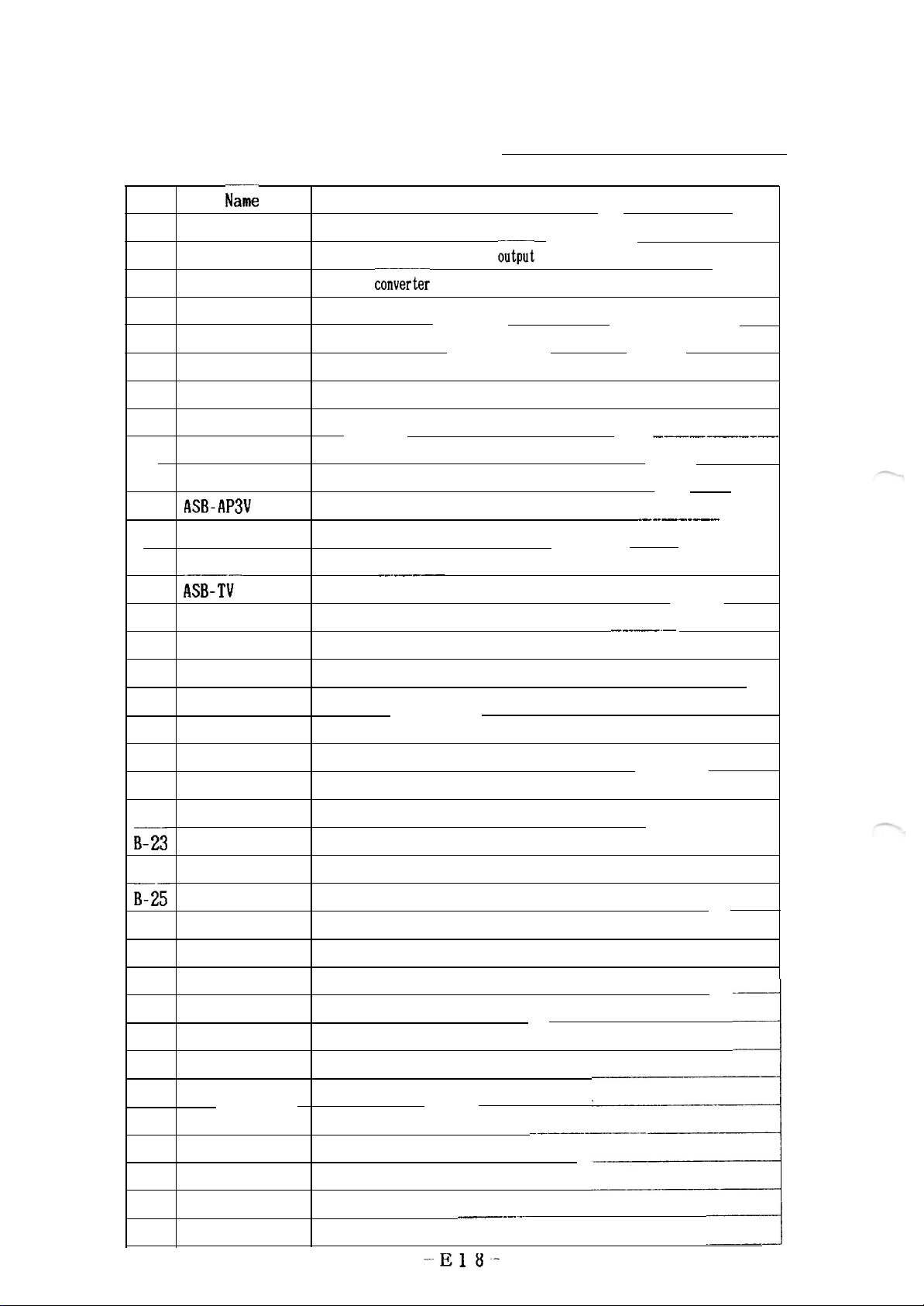
CHECKING LANDS (7)
No.
B-1
B-2
B-3 WLB-5V
B-4
B-5
B-6
B-7
B-8
B-9
..—
B-10 ASB-APGND
B-n
B-12
B-13
B-14
B-15 ASB-HOSEI
B-16 ASB-TVVREF
B-17
B-18
B-19
B-20
B-21
Na;e
WLB-CTRL
WLB-12V
DC-DC converter-control terminal
DC-DC
DC-DC
converter 12V
conver;er
WLB-VCC1 DC-DC converter input
WLB-GND
DC-DC converter
ASB-PCGND GND for photo coupler
ASB-PCOA
ASB-PC3V
Aperture photo interrupter output
3.3V for photo coupler
——
ASB-APMG Aperture Mg signal
GND for aperture Mg
ASB-AP3V
ASB- AEL
ASB-PULSE
ASB-Tii_
3.3V for aperturellg
AE LOCK SW
Mech. pulse output
—-._——
Tvdial output
Compensation dial output
Ref. voltage for dial resistor
ASB-TVAGND
ASB- ILLUMISW
ASB-PSAM
ASB-TVSELFLED
ASB-TVPC3V
GND for dial resistor
Illuminator SW output
—.
Mode dial output
Self-timer LED cathode terminal ‘
for Mech. pulse
3.3V
—
Function
.—.
;utput
5.5V output
—.
——— ———
GND
-
—
———
–
.-
-
——
—
.— —
——
———-————-
—.——
——
.—_.——-—
———
——
——_——
-
———
————.
-—
-—-. —.
—
-.———
—
—— .—
.
—-—
——
—
B-22 ASB-MCHARGE
B-j3
ASB-COUNTER
B-24 ASB-MAKISW
B-2~
ASB-TV3V
B-26 ASB-TAJYU
B-27 ASB-R1
—
——
—
Charge compl-etion switch output
——..
Counter SW output
Film advance SW output
3.3V for self -timer LED
—
Not in use
R1 switch output
——
—
1
——
-.-.—————
—
——
z
——-—
—-
ti
-E18-
Page 3
0
o
/?
0
u
00
0
(m
0
0
6)
0
0
2
o
0
I
m
.
Page 4

10
p
Uuuuuuuuq
(
00
—
0
o
u
o
00
00
0
0
0
0
0
0
o
(-
0
L
0
0
0
o
0
-1
o
(-6
L
N
0
Page 5

–E21–
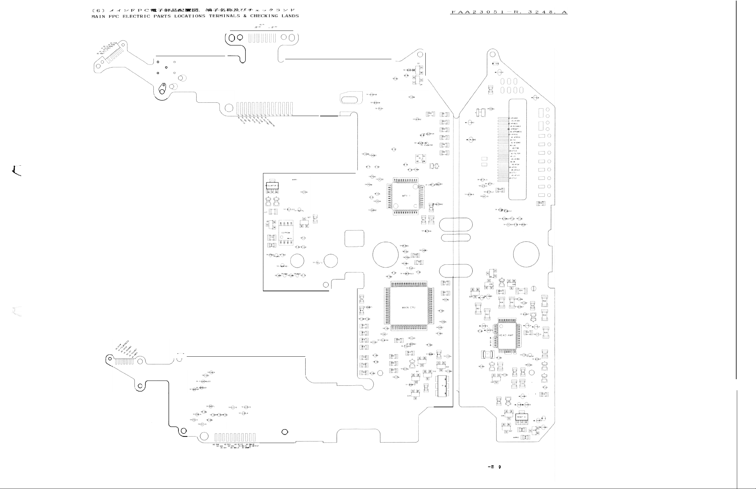
[71 SWITCHES
NikOfthttps://manualmachine.com/Ff@J
FAA23051–R.3248.A
a
Page 6

–E22–
.“
m
.
FAA23051–R.3248.A
Page 7

F4
ADD-
EEF’ROM DATA
CONTENTS
RESS
0
AF flag
A/B
1
2
Absolute value of 11 compensation (at F2. 8)
3
Absolute value of 12 compensation (at F8)
Hard AGC compensation value
4
5
K5
6 K8
7
Difference light (body)
Rewinding time
8
9
spot metering level (changes h l/8Ev w MB)
10
TTL
11
Shutter speed adjustment (M 118000 : 2.5 ~s per lLSB)
1’2
13
-,
.14
.15
.16
17
18
19
20
21
22
23
24
25
26
27
28
29
3
0 Error flag data
3
P
1 Light metering start time
2 Off delay time of Cs (Temperature shift is disused)
3
33 ThreshOld
3
4 Inclination
3
5 Aperture adjustment data
3
6 Aperture adjustment data
3
7 Aperture adjustment data
3
8 Aperture adjustment data
3
9 r
40 r
41-
51
52-
127
(6
bit:Ll, 7 bit:L2)
balance compensation value (X
factor compensation coefficient (at F2.
ber P)
8)
factor compensation coefficient (at F8)
38:film
level
Vcc r adjustment (writes adjustment value in FPC assembling)
~
Vref.
Vref.
adjustment of integer ( -ditto-)
r adjustment of decimal
Aperture adjustment data
Aperture adjustment data
Preliminary film advance adjustment
Preliminary film advance adjustment
Parameter for Cs-mode
Flag data for Cs-mode
Delay time for MF-24
Threshold of B.C. temperature characteristic
Incl inat ion of B.C. temperature characteristic
Voltage of release lock level
Guaranteed voltage of
Voltage of No power-hold level (O second timer level)
Parameter for Cs-mode
Parameter for Cs-mode
Mirror-down pulse number
of B.C. temperature characteristic (–5 0 C)
adjustment of spot metering (writes value in FPC assembl in
adjustment of TTL
Factory used only
(changes by
DCjDC
of shutter temperature character istic(6.
end rewound, O:film end left outside
l/12EV per
lLSB)
( -ditto-)
converter
( -ditto-)
Shutter release times, Frame number
(NEW
FIXED I
130
208 “ “
68P sldeg
) 17
g)
/
CF’U)
VALUE TO BE WRITTEN
‘~cpDF I ‘t!~ij
. . . . .
48
0
o
20!
“
38
OrO
o
0
38
o
“
+ +
+
o
o
2!
o
o
176 “
240
10
1!
5:
74 “
39
“+
8
13
25 “
2
1+
+
“
+
“ “
e
“ “
+ +
+
+
“
“
+
+
+
“
“
+
“
o
6
25
0-
1+
1-
1
6
o-
0
-
+
“
+
+
“
+
+
o- “
/
/
/ / /
0
@pg~d
t lines
Fixed data
: Do not change the data except address
Initial data of Main FPC unit for repair parts :
Fixed data and roughly data are written in FPC assembling.
Standard data
Note
: These are general data. Data are not yet decided.
: Do not change the data address 52 to 127.
1/2
8.
Page 8

x
Meaning
of
address
30 flag data (different from old type CPU)
128 : Power voltage falls below DC/DC converter guaranteed voltage level.
64 : Closing curtain SWfails to turn on even if closing curtain Mg turns off.
8 : Mechanical pulse fails to be output 255ms during charging.
4 : X contact is closed without T setting.
2 : Correct pulses are not output while aperture control is carried.
1 : 40
m
more aperture pulses are generated after aperture Mg turns on.
If the above number is writen in the address 30 of EEPROM, it means
that the mentioned trouble happened in the camera. If two
troubles have happened, added number is
number in address 30 is 192, troubles mentioned in
the past.
Note : 1. If the shutter is released while depth-of-field oreview button is
depressed, the number
trouble did not necessarily occur.
2.
After
rewi
r, be
* EEPROM list of Malti Photomic Finder
‘2”
sure to change the number in address
or more
shown.
For example, If the
’128
and 64” in
is written in address 30. The actual
30
to
0:
1:
2:
3:
4:
5:
6:
7:
Note :
Compensattion value at center (five-part SPD) l/8EV per lLSB
Compensattion value at upper-left (five-part
SPD)
Compensate ion value at upper-right (f ive-part SPD)
l/8EV per lLSB
l/8EV per lLSB
Compensattion value at lower-left (five-part SPD) l/8EV per lLSB
Compensattion value at lower-right (f ive-part
Not in use.
Not in use.
Not in use.
If a customer request You to change the meter characteristic to over or
under exposure, change the value in address O to 4 by the same degree.
SPD) l/8EV per lLSB
2/2
 Loading...