

Page 1

Nikon
mm m mm
Instruction Manual
Bedienungsanleitung
Manuel d’utilisation
Manual de Instrucciones
Manuale di istruzioni
Ai
S
a
a
a
Page 2

0*B
-------------
ENGLISH
-----------------------------
DEPTH OF FIELD TABLE -
PHOTOGRAPHIC RANGE WITH CLOSE-UP ATTACHMENT-
DEUTSCH
SCHARFENTIEFE-TABELLE--------------FOTOGRAFISCHE BEREICHE
MIT DEM NAHAUFNAHME-ZUBEHÖR -
FRANÇAiS
-------------------------------
PROFONDEUR DE CHAMP
RAPPORTS OBTENUS EN PROXIPHOTOGRAPHIE ET
PHOTOMACROGRAPHIE
ESPAÑOL -
----------------------------------
PROFUNDIDAD DE CAMPO-------------------RANGOS FOTOGRÁFICOS
CON ACCESORIOS DE ACERCAMIENTO
6-IOH
------
35H
------
37K
Page 11
Page 36
Page 38
- Seite 15
- Seite 35
Seite 37
— Page 20
— Page 35
— Page 37
Pàgina 25
— Pàgina 35
Pàgina 37
ITALIANO -
PROFUNDITA DI CAMPO-------------------------------------------FOTOGRAFIA CON DISPOSITIVI PER RIPRESE CLOSE-UP
■ Pagina 30
Pagina 35
Pagina 37
Page 3

72mm ХУ '} > ^ ^ "J У°
0:S'fz LF- I
72mm snap-on front lens cap
Rear lens cap LF-1
Aufsteckbarer Fronfdeckel 72mm<#>
Hinterer Objektivdeckel LF-1
Bouchon avant à emboîtement 72mm
Bouchon arrière LF-1
Тара frontal а presión de 72mm
Tapa trasera del objetivo LF-1
Tappo anteriore da 72mm dia.
Tappo posteriore LF-1
Page 4
¥Ä1.
Photo 1
Foto 1
Fig. 1
Fotografía 1
¥Ä2.
Photo 2
Foto 2
Fig. 2
Fotografía 2
¥Ä3.
Photo 3
Foto 3
Fig. 3
Fotografía 3
Page 5
® ® ®
Abb. A Ilustración A
Figura A
Il B must. B
Abb. B Ilustración B
Figura B
n c must, c
Abb. C Ilustración C
Figura C
Page 6

Ш
«P
/-Ч
s
§a
«il ©
о
S g
■ю -g;
i! J
N/” Vs
Л
V
Í' J r-v
+i^ ^
©©©©©i©
V
V
'■R
‘-R
S
ë
n|p
g
iliia
b.
Ш
Э
s
iÜ O
©
©
л
ÿ, fti
П !?' Ш1 ЕШ Z'
^ 2 Й ^ M
>< L Ш inl uu
II
^01
s
i
y
■R
Л
II
S
ÍS
M
та
ir- :t'
ÜJ
0
0
®
\)
G
Щ
□П
tü
8-1^
É:
№
©
y
M
_)
Ш
+¿
ftp(
m
№
3
JTT
Ш
ÏC
fv
a
0 0
œ
m
11
Л
1
□
Л
П
G 4Î^
#
-b
Sü
^(C
-П-- m
Л
Л
Ü üMO
Û Q
©
©
Л '<N
Л
1
'KÍ
Ш
Ш
5 2
< <
©
ü
Œ;
IJ
1
_J
JS
i)ai
i
an H
Ш
©
ш:
1 J
Y
Ш
—Ч
i
‘<N
Л
Q
®
1
í^
Л
il
Л
■ÎJ
Л
©
Page 7

и
£
2_j
ÎÎ
-tr
Î5
K h
-«- -,\
Л
1
Л
G iv
11
Î5
0P0
V
m <^a ■M
S
Ъ
■b)
Г)
g'
'Г>
AJ P
AJ
Ih
<)a
'•С!
-R
Ì! Ш
Й
IJ
S
^i~-
<
00
-Ч
Li_
:ü>
Hb
Л
Ш
П
■Й
11
K
'K r<
Л
■R 11
Л
r>
1
+7
h
T
-«-
П
Aac)l'■16
^
1
H
■k
■rt
ojè
ъ
Ш
<
i!J
Л K
П
-R
G
11
)l
k
P
Л
\J
A
ri
,
P
!?
1
1
t-
№
»
•W
H
n
АШ
.que
* Ш
•cr
O
(Z
O
Ü
roŒ
E
CO
ü
O
Q AJ
O
Q Ка
G
Л
П
,
îi
H
Л 0
GU'■R
Í1 °h
■b
■l^
Ш
G
iL*
Ка 'R
S
H 4a
_)
ir-
Й]
«J
‘■iî ■e
1 Ì
'k!
Ы G
M
Ш
m>^
S
•S;
_J ij
lii ■C
K
■R
1
+0
h
K
i>
Ка 1}
V-01
ij^k■k'
fÊ
G
Ш
Ш№< Ш
'K
Л
y
Î5
к
P
■C 4;
<n
-Í- J
Л
°u
%
Ы
‘■fc
«K
<w
Ш
G
-Í-
Л
\J
+t
tfi
f::
G
■w
-S'
№
R
ЙС
P
■M
Ш
inl
oa
«
-s
•R
,
■11^ 4p
-c
8
Íct>
■k tí
n
«b
P |ш
'■Q
AJ
1 )
Í?
1 )
!Î)
чР
K
■Rk-s
h
1
i^
SX-
R
G
^Li
-S' ■w
IDE
-S'
:;;;,
It
s
0
■w
S
P
0
•k6
U ,
m
■;ç
,
âS
P
_p
e
¡J
ië
M 5^
,
P
lil
R
#
Ф
m
4-
-fp
Ш
•ŸÜ
G
-Í-
1
K Л
Ih
»
-Í-
Л
1
П
1ii
R
r<J
U
Ш
n
ü
Ä
■E
,
^L!
M
H
O
k
■M XJ
N
Ш
U
P îb
Ш
Щ
4p
) J
I )
«
S
Jg œ ГЙ
R“:
1
Ф
г )
+ÿj
,
m
ffl
tê
œ
im
M
G
,
V
ifC
îh
k
Ih
iK
■R
■R
■H>
,
Í5
lïi
P
сш^
0
IJ
AJ
■Ч,
U
m
P
■c
4a
G
'K
Л
Л
G
V
M
0
■t6
Ih s
IjO
•Ш
ii
-R
s/
Page 8

- a J: Ü-'-y--Ь'Д э >1;йф Lxlt < fc 'S
Ь'ф
■ ¥«сЛ@СРи11-§-Й,*йх=| >AF(:t- Ь 7í-* Д) Й> tOTSÍtíSjiírÍT
Ì tzitxnbcnx-t ^ Ætlfc и . +Д'й'-Д1'й; 1J L Í Tt, Ь 7 Ï —й д№В1^Й5-
ЙХ Lïf. #1сШйсйШСИ7;г;Ш< tiíi\
■ TI£(73 7 7fe+)-U-B, îtJÈcrou>X'BBi‘M-tB44'T'< fc'ÿi.'.
X- MÍ¥U > Д'РК-иРКЧ кК1 и > Д\ X-V'l > Д'ВВ-4, BR-2, К2
(4'Ь\ РК-1 \(ПКЬ Ч 12ИРКЧ 1А, Zf - ь ч > Д"ВН-4СИВВ-6, ВВ-2 121JBR-2AÍ-A'
ffiffl < fc SL'J
■ DX-I 7 дХ >7"-{да >F3AFffl) £Ш*ё-Ь-й-ТГО7®ДИТв Í1+A,„
DC IJ
DC U >7"п -y ДтУ7 >írff CÍC*!B, < Т^Ш^ВЖи
7-) tic, ÎS¥#BÎÎLT0ÙÆ<7>,-y7®tiÎr J: <-ri.*i-ê-aF(7 □ > И tlJBDC U > 7'
íriHlfSS-tíír. (ИА)
«¥№?r-> д-7'В|*-оА; ì 4*У:ВЙ-:71*5'Й < Т5ВВ, DC U >77|гВ>Д'(ЛКи(а
Ì^CgffiB-b-у h LäT. ifc, DC=i > Ь p-;uu >7"5-®СвсйШЙВ U*#Aj.-g¡<¡*
Bir -y Ц-*7 £ B¿ y 77 I- 7 У1--Й Д1Й<Св'-'Уз t)Xe í То
4 Ж(П\Х9ШШ ir 7#fis < ft S в.
I : оси>7'5г-Ь'уЬСТ1.'йвчйяб-е-Го
ЧШг : BCJT-HPJjB-te-yl'LfcttSXty
2|:ез : F(7P>l')®JB-t'yFLfcttâ4X't;
• В> b^4o-|±OTfâl£DC и >7"írlallíí1í ÏT £ f> Ь й«1ВаТ L ì в ä Г„
DC U >7'S-t -у I- rsti'é-B'jZ'-f £"> 1''ё-Ь-й-(йтВ^?4'дТ < fc',? в.
ífc, В- Ь 7 4--Й 7íffyB#, ->7 7 7-тК7 fa J; 57 я P ,у Д
ФВОС и >7'Ìr[il$iS-tì-T С f> Ь B-rBiiTroXC'ä.B < fc'S i-B
• СОТВВД'В, DCU >7'(йШЙ«'ШгР(Рв1](Л2 £ВЙ1(Л2СОф*) IFê'ÎBtifcli'ê-Be
*OT»<**ír5SÍSL ït. DC'J £ BJ: CϧltS®£ f> K»ii*B
Д'ВЙ'ФС|;Т(ЙТ-7;Ф,Ш< fc'i?B. DC«BËfÈffla#(B f> h-g-irtiB, »litgS (œ)
<й-(Ш4-йдТ1е1^Фï>=t 9 Bit Д TL'ÌT. Í fc, ilfyîÈSf ü D C P > I- p-;y U >
7'colè® B J; Д T B I. I m Í TL'Ä'AcL'lt-ä-Ai* Ч ito
• D С (ÎSi4itt1iW:tBtiW:<niëMt(nmif--Êfbitm) BípTS
t4Íto itZo D СГОЙ1ЖВ7 дф >7"-[*lT'Bïilî.*'llïlÎ(fcâô, ISLÍiC írÍTp
Тй'Ь Bg55-OTÍií*T-rftffl < fc'S L'„
Page 9

a > b -è -b it
Z л 1^ > xa А-м-щ и íSA г-ït с *T L'â г о
ХЛ>АР{*- |-7*-*х) ЛУ^Иа>ШЛ-^ЬаТ-^- Ь7
-ê-li, А-М-Щ*х.--1^7 >5rffLÍCA'b A-M-tJÍS^U >7"5г[1]ЕЬ, А отеИС-й'у Ь L T
Л'‘Ь7®Д <
7Z и г;рт-f > h 5-ÍTT tl-ê-BА-м-щйя □ -y X yt-:X > ír}f L **' ь а-м«йя
и >7>Hl$íi¥-tí. M<n-(jïBC-t2-у Ь LTZ-ftffl < ft S V,'„
7 r-f > y-я i' i; - V t c7)ia*-é-t>-tí-
хл >F4, F3, F2'> U -X*x 5-7:74 lzlii-aii7i7 y"f >7'-XX 'J ->*'* >J , U
>x"rox-f ftiicobOTS-aziz ¿*'T'# Í r, z®a>x'icii
L 7 X 7 > X - X X ü - > a S<»a ‘J T-T „ ( 4' fc\ х-еш a pg l x a * t* # * x 5 -x: 7
Х<7)ЙЯ1Й0Я*5:#4+ТГ#Й?, < fcÿ4.)
i«0ö5i^ä:'Xf7 h-è-b-tì-rogeìictt
и**
О
А
F4 DP-20#
Р4 DA-20#
F3‘, F2
A/L G1 G2 G3 G4 Н1 Н2 НЗ Н4 К/Р м Т**
а
о
О О
(?)
(%
О
(+1/2) ¡+?/2)
(+?/2)
© : ixaX'To
о : ÍJIiíOT—SB*'$-X'_aa < < 4‘j íTA'efflX"# íT.
д : X7‘i;-у И77ё-й«ВЛ,х*7*\ f> b-ê-t7tiCBffl)t_h® L í ■а-4.
() : F4, F2-> и-Х'лх ( )ЙОТШ»<ЛВЖИЖЛ«*^Т-Г. {F4X)K[ilii
Œ(Î7 х7 >Х'-ХХ U->atHÎ*ŒX4XJFXÎ7-yX < fcêi.'J
^í»1 : ЙЯЗХзйШХГо fcfc'L, мхх и-XOTif-ê-, *fyfêi:KfêtU-hOTifiiÎiifi(zffl
7bti5fc№, ZCOPfiU Xii* и í-Й-До
♦ : F3->u-x'*x5aB!±ií*iEOT«'Siií)‘j ä-a-До
** : F2-> и - х'й X xcaTfc-ty'uxx u->as¡ и í й-До
F4, F3, F2-> Ч -Х'Ы?|-(ЛЛХ 5 5rZfÈfflX)t#-ê-, К2, В2, Е2 X X U ->B7tl7tlK.
в, Ехх >отщ%гш< tz$i\
F
Page 10

fi'j'-scij О'у^ (тв#м)
->Л’'уУ-Я^аъШ9тч. Ш‘)Ч>У'^Ш'ШЧВ^Ч (^
u>7S) T-HS:LTíj< A¿*<ffijtsíTo М'1'ВШчта -уугъщ-^а. í-ta>x
(ПШ Ч и §йи (I6)ï Tiues-Ô-Î-To iivCæ'J'gtJ □ 7 7
'J >7'(7)у5-ЙС79'|' KS-f+ä-To Z(Dt ÍM'№4 П уУ ил-сойП<п1^т1:Шт-Ь
(п*и>уп<пшь'^ишшх-тш(^лу-1 к'ё-ц-т < fc'êi,'„ □ у у ^тшт bt s
li, P 'У ÿ-fï. t s tSíi:?[í]liiJií SiT-Ä'J'gU P 'У 7 к éili Го
rtil7- Kro#t':^([iic)
РчШЬ'уХу— К4:ЙШТ%*§'ё'В1у>я'мЯ'СЙй'-уТ?|гЖи, Sa#itÄfilC 2îHt;
ISlLTllIlÈLT < fc-JL'o 7- KÎ-iRittrSité-lifltltfllClHlLTÆWiieicSLTilïfft
LT< tzil\
U УХ1Я ‘J Ï5L'±.(7)C'Œ,^
• ly>XOTitiSli, Г'Р^ИЙЛ'АЧ'Т-, -ГР U 5:«TfiæicLT < fc'Si'. 7ï—
7(,'i;£ê(l, ЩЬ*Ч';й;Шт|<ЛА$ AliSyK7rp-Д- (л:77—Л-) ^гГ'ж;!
■b-й-, «êA7, ttíSUOTA-i-'i 9Œ*:LTttl,'T < fc'í
L'o
• ■> > Г - ^ 7 > 4- £'í7):t«;SSI ti ЙЯ с® ffl L A4 ' T < í; S l. ' о
• 1у>Х*Ш0)>^ПГ>®5-|Ш<-А«)С, L37C7-í;u7-(7>efflírfct-r»LÍTo А > 7'
cT^eiiCli, 7-Kt-iêifiÿir.
• 1у >7Гг*7 Г-ГГЧ IC-íilífc Í âX\ 7-®fflCA Ь44'£ #li, -jZ'-f Ч>Х+ Г -у 7'
5- LTJb'L'T < fc'? Чо
• *etríA>7-5ríi®L'lz7j;ib7j.4>¿$li, il*t0*«iSfcí>Í7í>lii®(ÍX,
MLíAi: L'iifiitzftîÇLT < ízS Ч0
• 7(ЛА>7'(1, —gBlZíS-ftA'pxr'yi’íríífflLTl-'ír*', eìffilZS®*'* <'i í. t
SIB-rstf-é-AibiJ ifo УУ-У'(ПтЩ. *»¿7j:%iéí;íliigltT < ASI.'.
Page 11

tt Ш
% ш
:Л: □
e
U
> X
®
ÎE Ш
<■) g
K
J' & ‘J
* '
Ч
Йг
iîJJ
Ус
-7
'У
7 9
-k
S
è
Hi : 135mm
it : 1 : 2
№
йг : 6II7ÎÂ (+í*li*"^;7 1 iè)
т
Й : 18"
^ : оэ — 1 , 1 m ^ 4 ft (-ÌÌfifi)
g
s: 2-16 7 т-о^-йШШШШЧ ВШШ
□ -у
9 : п 'У ÿ> l^/ï—(; J; Ч f/ieiz а -у 9TjÊè
А : ШШШЧ
А : CPU ■ M7A<nt¡ 9 7 ■< Г:!.ШШть.
уПАч T-Bíixtja¿^iSijiÉ
'у
i : - zi>F 77 > ь
Ь ■У’-l'X' : 72mm (p = 0.75mm)
è : Й79гшп(Я;*}1)х I20mm{*ÿ :у7Э^'У i*:
РЛТ), ^**CI28mm
* : *C870g
C i2i¿^ít'7 -i i V ^ —
CL-38
'jy Vy--y No. 63
xl/n TC-I4BS
10
Page 12

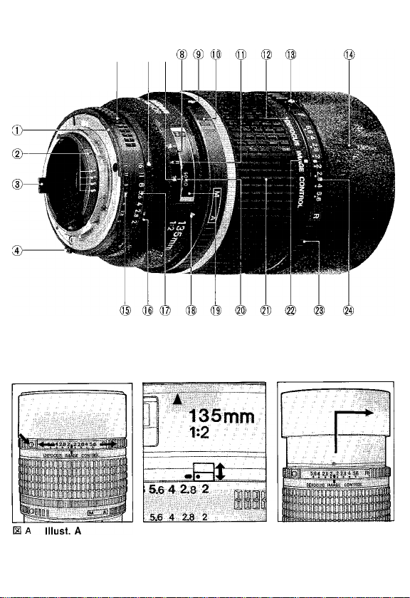
NOMENCLATURE
© Meter coupling ridge
@ CPU contacts
@ Aperture indexing post
© EE servo coupling post
® Aperture ring
® Aperture index/Mounting index @ Distance scale window
© Depth-of-field indicators: Shows
Depth of field at f/16.
® Infrared compensation index ® DC ring index
(white dot) (g) DC ring: Turn toward “R” side to blur
@ A-M ring button
@ A-M ring
® Distance index
@ Lens barrel See page 12.
(i|i DC ring lock button: Push to turn
DC ring.
Thank you for purchasing the AF DC-Nikkor 135mm f/2 lens.
Before using your new lens, read this manual carefully so you get the maximum
value from your lens now and for years to come.
Important!
• Be careful not to soil or damage the CPU contacts.
• Do not attach the following accessories directly to the lens; they could damage the
lens CPU contacts:
Auto Extension Ring PK-1, Auto Extension Ring PK-11, K1 Ring, Auto Ring BR-4,
Macro Adapter Ring BR-2 or K2 Ring.
(Use PK-11 A instead of PK-11, BR-6 instead of BR-4, BR-2A instead of BR-2.)
• This lens cannot be used with AF finder DX-1 (for the Nikon F3AF).
@ Built-in lens hood: See page 13.
® Aperture-direct-readout scale
® Minimum aperture lock lever
® Aperture scale
@ A-M index
(g) Distance scale
@ Focusing ring
the background or toward “F” side
to blur foreground. See page 12.
@) Aperture scale for image blur control:
11
Page 13

CONTROLLING DEFOCUS IMAGE—MAKING IMAGE BLUR
AF DC (Defocus image Control)-Nikkor 135mm f/2 enables you to defocus the
background or foreground. The lens’ rounded diaphragm opening makes ouf-offocus elemenfs appear as circular high-lighfs on your picfures.
While pushing the DC ring lock button, rotate the DC ring toward the R (rear) side to
blur the background, or toward the F (front) side to blur the foreground. (See lllust. A).
Toeffectivelyblur backgrounder foreground images, turn the DC ring sothef-number
on the ring that corresponds to aperture in use aligns with the index on the DC ring.
Turning the ring beyond the aperture in use lets you create a soft-focus effect.
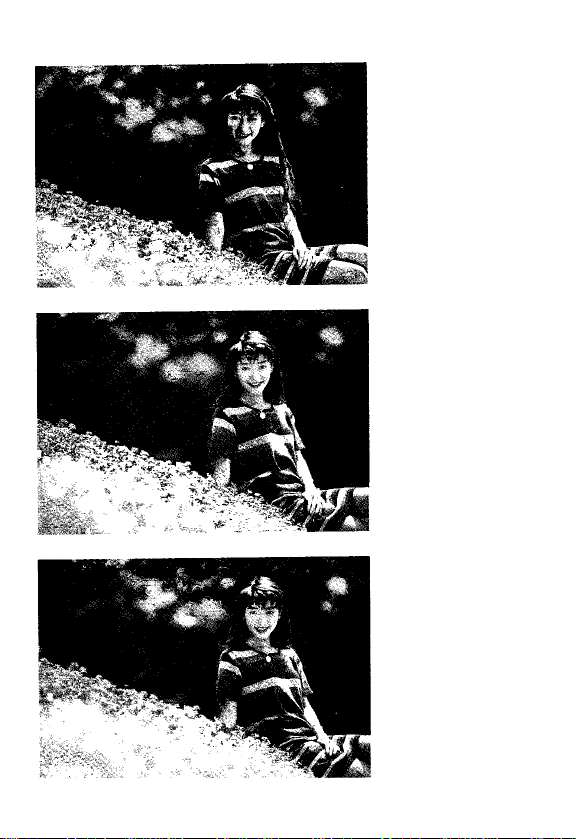
See photos on page 4.
Photo 1: No image blur
Photo 2: Background images are blurred
Photo 3: Foreground images are blurred
• With the DC ring at either the F or R side, the focusing ring may not show the
correct distance,
• Defocus control should always be performed before focusing. If you rotate the DC
ring after focusing, or during focus lock in autofocus photography, your subject will
be out of focus.
• The effect of defocus image control depends on subject conditions such as
subject-to-background distance, subject-to-foreground distance, etc. As you
cannot verify the results through the viewfinder, perform bracketing with the
DC ring at various settings to obtain the desired effect.
FOCUSING
This lens can be used tor both autofocus and manual focus.
To select autofocus, while pressing the A-M ring lock button, turn the A-M ring so
that “A” aligns with the A-M index. Also, set the camera’s focus mode selector to
autofocus position.
To select manual, turn the A-M ring so “M” aligns with the A-M index. Also, set the
camera’s focus mode selector for manual focus.
• With a Nikon autofocus camera, improperly setting the camera’s focus mode
selector and lens’ A-M ring may damage the camera body.
• With the DC ring set at either the F or R side, the focusing ring will shift slightly
from its original position.
Nikon Rear Focusing (RF) System
A system in which the rear lens elements move inside the lens, there is absolutely
no increase in the overall length of the lens barrel as the lens is focused closer.
12
Page 14

RECOMMENDED FOCUSING SCREEN
Various interchangeable focusing screens are availabie for Nikon cameras fo suit
any type of lens or picture-taking situation. Those which are recommended for use
wifh your lens are lisfed.
Screen
Camera
F4 with OP-20
F4 with DA-20
F3*, F2 o O
A/L C
D
G1 G2
( + 1/2)
G3
G4 HI H2H3H4 K/PMR T** U*‘
@
(-1)
(i|
0
I + V2)
(-f?/2)
F
®
A
@ = Excellent focusing
O = Acceptable focusing
Slight vignetting or moire phenomenon affects screen image, but film image
shows no traces of this.
A = Acceptabie focusing
■ The in-focus image in the centrai circular area may prove to be slightly out of
focus on the film. Focus on the surrounding matte area.
( ) = Indicates degree of exposure compensation needed for F4- and F2-series
cameras. For F4-series cameras, compensate using the Exposure
Compensation Dial for the focusing screens. (See the F4/F4s instruction
manual, page 78).
Blank box means not applicable. Since type M screen can be used for bofh
macrophotography at a 1:1 magnification ratio and for photomicrography, it has
different applications than other screens.
* For F3-series cameras, exposure compensation is not necessary.
** Screens T and U are not available for use with F2-series cameras.
For the K2, B2 and E2 focusing screens, refer to the columns on the K, B and E
screens, respectively. For details, also refer to the specific camera’s instrucfion
manual.
MINIMUM APERTURE LOCK
For progammed auto or shutter-priority auto exposure shooting, use the minimum
aperture lock lever to lock the lens aperture at f/16.
1. Set the lens to Its minimum aperture (f/16).
2. Slide the lock lever In the direction of the aperture ring so the white dot on the
lever aligns with the orange dot. (Illust, B)
To release the lock, slide the lever in reverse direction.
USING BUILT-IN LENS HOOD
Pull out the hood and turn it counterclockwise for two rotations. (See Illust. C). To
store, turn the hood clockwise and push back.
13
Page 15

LENS CARE
• Although you should always keep lens surfaces clean, rough cleaning must be
avoided. To remove grease or fingerprints from the lens surfaces, wipe with a soft,
clean cotton cloth moistened with alcohol.
• Never use thinner or benzine to clean the lens.
• To protect the lens surface from dirt or damage, use of an L37C filter is recom
mended at all times. The lens hood also helps protect the lens.
• Cover lens with lens cap when lens is not in use.
• Attach both front and rear caps when the lens is stored separately.
• If you will not use the lens for a long time, store it in a cool, dry place away from
direct sunlight.
• Reinforced plastic is used for some parts in the lens unit; to avoid damage, take
extra care to never leave the lens in an excessively hot place.
SPECIFICATIONS
Focal length:
Maximum aperture:
Lens construction:
Picture angle:
Distance scaie:
Aperture scaie:
Minimum aperture:
Diaphragm:
Focusing:
Exposure measurement:
Mount:
Attachment size:
Dimensions:
Weight:
135mm
f/2
7 elements in 6 groups (plus built-in dustproof glass
front plate)
18°
Graduated in meters and feet from 1.1m (4 feet) to
infinity (oo)
f/2 to f/16 on both standard and aperture-directreadout scales
Provided
Fully automatic
Nikon Rear Focusing (RF) system
Via full-aperture method for Al cameras or cameras
with CPU interface system; via stop-down method for
other cameras
Nikon bayonet mount
72mm (P = 0.75mm)
Approx. 79mm dia. x 120mm extension from the
camera's lens mounting flange; overall length is
approx. 128mm
Approx. 870g
OPTIONAL ACCESSORIES
72mm screw-in filters
Hard lens case CL-38
Flexible lens pouch No. 63
Teleconverter TC-14B
14
Page 16

BEZEICHNUNG DER TEILE UND
© steuerkurve ®
@ CPU-Kontakte ®
©Anschlag für Blendenkupplung
® Kupplungsstlft für automatische ®
Blendensteuerung @
® Blendenring ®
© Blenden-ZMontagelndex @
@ Schärfentlefenskala @
© Infrarot-Kompensationsindex (§)
(weißer Punkt) (2)
© Entriegelungstaste des A-M-Ringes
® A-M-Ring
@ Entfernungsindex
® Objektivtubus
(Tä) DC-Ring-Entriegelungstaste: Drücken, @
damit der DC-Ring gedreht werden kann.
@ Eingebaute Gegenlichtblende:
Siehe Seite 17.
Vielen Dank für das Vertrauen, das Sie Nikon mit dem Erwerb des AF DC-Nikkor 135
mm f/2 entgengebracht haben. Bitte lesen Sie die folgende Beschreibung sorgfältig
durch, bevor Sie mit Ihrem Objektiv arbeiten, damit Sie viele Jahre ungetrübte
Freude daran haben.
Wichtig!
• Sorgen Sie dafür, daß die AF-Kontakte unter keinen Umständen verschmutzen
oder beschädigt werden.
• Setzen Sie bitte folgendes Zubehör nicht an das Objektiv an, da es die AF-Kontakte
beschädigen könnte: Die Automatik-Zwischenringe PK-1 und PK-11, die
Zwischenringe K-1 und K-2, den Automatikring BR-4 und den Umkehrring BR-2.
(Verwenden Sie PK-11A statt PK-11, BR-6 statt BR-4 und BR-2A statt BR-2).
• Dieses Objektiv kann nicht mit dem Sucher DX-1 (der Nikon F3AF) verwendet
werden.
BEDIENUNGSELEMENTE
Skala für direkte Blendenablesung
Hebel für Verriegelung für kleinste
Blende
Blandenskala
A-M-Index
Entfernüngsskalenfenster
Entfernüngsskala
Einstellring
DC-Ring-lndex
DC-Ring: Drehen Sie diesen Ring in
Richtung “R”, um den Hintergrund,
und in Richtung "F”, um den
Vordergrund unscharf abzubilden.
Siehe Seite 16.
Blendenskala zur Steuerung der
Bildunschärfe: Siehe Seite 16.
15
Page 17

BEEINFLUSSUNG DER FOKUSSIERUNG —GESTALTERISCHE UNSCHÄRFE
Das AF DC-Nikkor 135 mm f/2 (DC = Defocus image Control = Veränderung der
Fokussierung) ermöglicht Ihnen, die Schärfe des Flinter- oder Vordergrundes zu
beeinflussen. Die Blendenöffnung des Objektives bewirkt dabei, daß die außerhalb
des Schärfenbereichs angeerdneten Bildelemente auf dem späteren Foto als
kreisförmige helle Bildpunkte zu sehen sind.
Während Sie die Entriegelungstaste des DC-Ringes drücken, drehen Sie den Ring in
Richtung R (Rear = Rückseite), üm den Flintergrund, oder in Richtung F
(Front = Vorderseite), um den Vordergrund verschwimmen zu lassen (siehe Abb. A).
Damit Hinter- oder Vordergrund auch wirkungsvoll unscharf werden, drehen Sie
den DC-Ring so weit, bis die Blende auf dem Ring, die übrigens mit der Arbeitsblende
übereinstimmen muß, dem DC-Ring-lndex gegenübersteht. Durch das Verstellen
des DC-Ringes über die Arbeitsblende hinaus erhalten Sie einen kreativen
Weichzeichnereffekt.
Siehe Bilder auf Seite 4.
Foto 1: Keine Unscharfe im Bild
Foto 2: Hintergrund unscharf
Foto 3: Vordergrund unscharf
• Befindet sich der DC-Ring entweder auf der F- oder der R-Position, kann der
Fokussierring nicht die korrekte Entfernung anzeigen.
• Die Beeinflussung der Fokussierung sollte immer vor der eigentlichen Scharf
einstellung durchgeführt werden. Geschieht dies nach dem Scharfstellen oder
während einer Schärfespeicherung im Autofokusbetrieb, wird Ihr Hauptobjekt
unscharf abgebildet.
• Die Wirkung der Fokussierungsveränderung ist abhängig von solchen Faktoren
wie der Distanz zwischen Objekt und Hintergrund, zwischen Objekt und Vorder
grund usw. Da sich das Aufnahmeresultat nicht im Sucher überprüfen läßt,
erstellen Sie eine Aufnahmereihe mit unterschiedlichen DC-Ring-Einstellungen, um
den gewünschten Effekt einzukreisen.
SCHARFEINSTELLUNG
Dieses Objektiv kann mit automatischer (Autofokus) und manueller Scharfeinstellung
benutzt werden.
Um auf Autofokusbetrieb zu schalten, drücken Sie die Entriegelungstaste des
A-M-Ringes und drehen diesen Ring gleichzeitig so weit, daß das "A” dem A-M-Index
gegenübersteht. Stellen Sie gleichfalls den Fokussier-Betriebsartenwähler der
Kamera auf Autofokus-Position.
16
Page 18

Für die manuelle Scharfeinstellung stellen Sie den A-M-RIng auf “M”, so daß das
"M” auf den A-M-Index ausgerichtet Ist. Auch der Fokussier-Betriebsartenwähler
der Kamera Ist auf “M” zu setzen.
• Durch die nicht korrekte Einstellung des Fokussier-Betriebsartenwählers der
Kamera und des A-M-Objektivringes kann bei einer Nikon-Autofokus-Kamera das
Kameragehäuse beschädigt werden.
• Befindet sich der DC-Ring entweder auf der F- oder R-Position, verschiebt sich der
Fokussierring ein wenig aus seiner ursprünglichen Stellung.
Nikon-Rückteil-Fokussier
Dies ist ein System, bei dem die hintere Linsengruppe im Objektivtubus verschoben
wird, wodurch sich die Gesamtlänge des Objektives selbst bei Einstellung der
kürzesten Aufnahmedistanz nicht ändert.
EMPFOHLENE EINSTELLSCHEIBEN
Für Nikon-Kameras stehen verschiedene, auswechselbare Einstellscheiben zur
Verfügung, um jedem Objektiv und jeder Aufnahmesituation gerecht zu werden.
Die zur Verwendung mit Ihrem Objektiv empfohlenen Einstellscheiben sind aufgelistet.
\Einstellscheibe
Kamera
F4 (mit DP-20)
F4 (mit DA-20)
F3V F2
@ = Ausgezeichnete Scharfeinstellung
O = Brauchbare Scharfeinstellung
A = Brauchbare Scharfeinstellung
( ) = Zahienwerte in Klammern zeigen die erforderliche Belichtungskorrektur für
Ein Leerfeld bedeutet unbrauchbar. Da die Einstellscheibe Typ M für Makrofotografie
bei einem Abbildungsverhältnis von 1:1 sowie für Mikrofotografie verwendet wird,
unterscheidet sich ihre Anwendung von den anderen Einstellscheiben.
* Mit den E3-Serien-Geräten ist keine Belichtungskorrektur nicht erforderlich.
** Die Einstellscheiben T und U können nicht mit Kameras der Serie F2 verwendet
Eür die Einstellscheiben K2, B2 und E2 siehe die Spalten für die Scheiben K, B bzw.
E. Siehe auch die Anleitungen der jeweiligen Kamera.
A/L G1 G2 G3 G4 Hl H2 H3 H4 K/P
»
«
O o
O
( + 1/21
lil
1?1
(+?/2)
(+?/21
a
Leichte Vignettierung oder Moiré im Sucherbild, nicht jedoch auf dem Film.
Der in der Suchermitte scharf erscheinende Aufnahmegegenstand kann auf
dem Film leicht unscharf sein. Fokussierung auf dem Einsfellscheiben-Umfeld.
Kameras der Serie F4 und F2. An einer Kamera F4/F4S am
Belichtungskorrekturwähler für die Einstellscheiben kompensieren. (Lesen Sie
hierzu bitte die Seite 78 der Bedienungsanleitung der F4/F4S.)
werden.
u**
T**
M
F
a
a
A
a
17
Page 19

VERRIEGELUNG FÜR KLEINSTE BLENDE
Verwenden Sie für Programmautomatik oder Biendenautomatik mit Zeitvorwahl den
Hebel für Verriegeiung für kieinste Biende, üm die Blende bei f/16 zu verriegein,
1. Stelien Sie das Objektiv auf die kieinste Blende ein (f/16).
2. Schieben Sie den Verriegeiungshebei in die Richtung des Biendenrings, so daß
der weiße Punkt auf dem Hebel mit dem orangen Punkt ausgerichtet ist
(siehe Abb. B).
Zur Freigabe der Verriegelung schieben Sie den Hebel in die umgekehrte Richtung.
VERWENDUNG DER EINGEBAUTEN GEGENLICHTBLENDE
Ziehen Sie die Gegenlichtblende nach vorne und drehen Sie sie zwei Umdrehungen
gegen den Uhrzeigersinn, bis sie verriegelt ist (siehe Abb. C). Um sie wieder
einzufahren, drehen Sie die Blende im Uhrzeigersinn und schieben Sie sie dann
zurück.
OBJEKTIVPFLEGE
• Die Linsenoberflächen des Objektivs sollten jederzeit saubergehalten werden.
Vermeiden Sie jedoch grobes Reinigen mit ungeeigneten oder harten Mitteln.
Wischen Sie Fett und Fingerabdrücke mit einem weichen, sauberen Baumwolltuch,
das mit etwas Alkohol befeuchtet wurde, ab.
• Benutzen Sie unter keinen Umständen Benzin oder Verdünner zum Reinigen
des Objektivs.
• Um die Frontlinse vor Schmutz und Beschädigung zu schützen, ist es empfehlens
wert, ein Nikon-UV-Filter L37C in das Filtergewinde zu schrauben. Es kann
auch ständig auf dem Objektiv bleiben. Darüber hinaus bewährt sich auch die
Gegenlichtblende als Frontlinsenschutz.
• Setzen Sie den Frontdeckel auf das Objektiv, wenn Sie Ihre Kamera nicht benutzen.
• Wird das Objektiv einzeln gelagert, bringen Sie Front- und Rückdeckel an.
• Arbeiten Sie mit Ihrem Objektiv längere Zeit nicht, lagern Sie es an einem kühlen,
trockenen Platz, wo es vor direkter Sonneneinstrahlung geschützt ist.
• Einige Bauteile des Objektivs sind aus einem stabilen widerstandsfähigen Kunststoff
gefertigt.
Um trotzdem Schäden zu vermeiden, achten Sie ganz besonders darauf, daß es
niemals an einem sehr heißen Ort aufbewahrt wird.
18
Page 20

TECHNISCHE DATEN
Brennweite
Maximale Blendenöffnung:
Optische Konstruktion:
Bildwinkel:
Entfernungsskala:
Blendenskala:
Verriegelung für kleinste Blende:
Blendenart:
Scharfeinstellung:
Belichtungsmessung:
Anschluß:
Filtergewinde:
Abmessungen:
Gewicht:
SONDERZUBEHOR
72-mm-Einschraubfilter
Fester Objektivköcher CL-38
Objektivbeutei Nr. 63
Teiekonverter TC-14B
135 mm
f/2
7 Linsen in 6 Gruppen (pius vorne
angebrachte staubdichte Giaspiatte)
18°
Unterteilt in Meter und Fui3 und zwar von
1,1 m (4 FuB) bis unendlich (oo)
f/2~f/16, sowohl auf der Standardskaia ais
auch auf der Skala für direkte Abiesung
Vorgesehen
Voilautomatisch
Nikon-Rückteii-Fokussier System-RF
Offenblendenmessung bei Kameras mit Al-
Blendenkuppiung oder CPU-lnterfaceSystem; Arbeitsbiendenmessung bei alien
anderen Kameras ohne Al-Blendenkupplung
Nikon-Bajonettanschiuß
72 mm (P = 0,75 mm)
Ca. Durchm. 79 mm x Länge bis Fiansch
120 mm; Länge über alles ca. 128 mm
Ca. 870 g
19
Page 21

NOMENCLATURE
© Index de couplage photométrique
@ Contacts CPU
@ Coupleur de l’ouverture
© Index de servocommande diaphragme
® Bague des ouvertures
® index d'ouverture/Index de montage
@ Echeile de profondeur de champ:
Affiche profondeur de champ à f/16
® Repère de mise au point en infrarouge
(point blanc)
@ Bouton de verrouillage de la bague
A-M
(rô) Bague A-M
® Repère des distances
® Barillet d'objectif
® Bouton de blocage de la bague DC:
Presser pour tourner la bague DC.
@ Parasoleil incorporé: Voir la page 23
Nous vous remercions pour votre confiance manifestée en AF DC-Nikkor 135mm f/2.
Avant d’utiliser votre nouvel objectif, veuillez lire attentivement les instructions qui
suivent pour tirer le meilleur parti de votre objectif tout de suite et pendant de
longues années.
Important!
• Veiller à ne pas salir ou endommager les contacts CPU.
• Ne pas fixer les accessoires suivants à un objectif, car ils peuvent endommager
les contacts CPU de l’objectif:
Bague d’auto-rallonge PK-1, Bague d’auto-rallonge PK-11, Bague K1, Auto Bague
BR-4, Bague d’adaptateur Macro BR-2 ou Bague K2.
(Utiliser la PK-1 IA à la place de PK-11, BR-6 à la place de BR-4 et BR-2A à la place
de BR-2.)
• Cet objectif ne peuf pas s’employer à l’intention du Viseur AF de DX-1 fixé à
l’appareil F3AF Nikon.
® Echelle de lecture directe d'ouvertures
@ Levier de verrou de l’ouverture
minimale
® Echelle des ouvertures
(il) Index A-M
® Fenêtre d’échelle des distances
(g) Echelle des distances
@ Bague de mise au point
@ Index de la bague DC
(2) Bague DC: Tourner vers le côté "R”
pour rendre flou l’arrière-plan ou
vers le côté “F” pour rendre flou le
premier plan. Voir la page 21.
(24) Echelle de l’ouverture pour le
contrôle de l’image de défocalisation:
Voir la page 21.
20
Page 22

CONTROLE DE L’IMAGE DE DEFOCALISATION—COMMENT RENDRE L’IMAGE FLOUE
L'AF DC (Defocus Image Control)-Nikkor 135mm f/2 vous permet de délocaliser
l'arrière-plan ou le premier plan.
L’ouverture du diaphragme arrondie de l'objectif fait que les éléments défocalisés
apparaissent comme des reflets circulaires sur les images.
Tout en pressant le bouton de verrouillage de la bague DC, tournez la bague DC vers
le côté R (“Rear”, arrière) pour rendre flou l'arrière-plan, ou vers le côté F (“Front”,
avant) pour rendre flou le premier plan. (Référez-vous à la illust. A). Pour rendre les
images de l’arrière-plan ou du premier plan effectivement floues, tournez la bague
DC de telle manière que le nombre f sur la bague, qui correspond à l'ouverture
utilisée, soit aligné avec l’index de la bague DC. En tournant la bague au-delà de
l'ouverture utilisée, il sera possible de créer un effet de mise au point souple.
Référez-vous aux figures de la page 4.
Fig.t: Aucune image floue
Fig.2: Les images de l'arrière-plan sont floues
Fig.3: Les images du premier plan sont floues
• Avec la bague DC soit sur le côté F, soit sur celui R, la bague de mise au point
pourrait ne pas indiquer la distance correcte.
• Le contrôle de défocalisation devrait toujours s’effectuer avant la mise au point.
Si vous tournez la bague DC après la mise au point, ou durant le blocage de mise
au point en prise de vues à mise au point automatique, le sujet ne sera pas mise
au point.
• L’effet du contrôle de l’image de défocalisation dépend des conditions du sujet
telles que distance sujet/arrière-plan, sujet/premier plan, etc. Comme vous ne
pouvez pas vérifier les résultats par le viseur, effectuez la séquence automatique
avec la bague DC sur différents réglages pour obtenir l’effet désiré.
MISE AU POINT
Cet objectif peut être utilisé aussi bien pour la mise au point automatique que pour
celle manuelle.
Pour sélectionner la mise au point automatique, tout en pressant le bouton de
verrouillage de la bague A-M, tournez la bague A-M de telle manière que “A” soit
aligné avec l'index A-M. D’autre part, réglez le sélecteur de mode de mise au point
de l’appareil sur la position de mise au point automatique.
Pour sélectionner la position “Manual”, tournez la bague A-M de telle manière
que “M” soit aligné avec l’index A-M. En outre, réglez le sélecteur de mode de mise
au point de l’appareil pour la mise au point manuelle.
• Aveo un appareil Nikon à mise au point manuelle, un réglage incorrect du
sélecteur de mode de mise au point de l’appareil et de la bague A-M pourrait
endommager le boîtier de l’appareil.
• Avec la bague DC réglée sur le côté F ou sur celui R, la bague de mise au point
se déplacera légèrement de sa position d’origine.
21
Page 23

Système de mise au point arrière (RF) Nikon
Un système dans lequel les éléments de l’objectif arrière se déplacent dans
l'objectif. Il n’y a aucune augmentation de la point de l’objectif s’effecfue à une
distance plus rapprochée.
VERRES DE VISEE RECOMMANDES
Différents verres de visée interchangeables peuvent être montés sur les appareil
photo Nikon. Il sont utilisables avec tous les types d’objectifs et dans toutes les
situations de prise de vue. Les verres de visée recommandés pour chaque objectif
sont répertoriés dans le tableau.
Verre
Apoareil
F4 avec DP-20
F4 avec DA-20 a
F3*. F2 « OOP
@ = Mise au point excellente
O = Mise au point passable
A = Mise au point passable
A/L B c D G1 G2
Léger vignettage ou effets de moire sur l'image du verre, mais le tilm ne
présente aucune trace de ces phénomènes.
L’image de la zone circulaire centrale paraît légèrement brouillée. Mise au
point autour de la zone tressée.
G3 G4 H1
®
(-1)
O
(+1/2) |+?/2)
( ) = Indique le degré de compensation d’exposition requis pour les appareils série
F4 et F2. Pour les appareils de la série F4, compenser en utilisant le sélecteur
de compensation d’expesition pour verres de visée. (Se référer au manuel
d’utilisation des appareils F4/F4s, à la page 78.)
Les blancs désignent des verres inutilisables. Comme le verre de type M est utilisé
pour la macrophotographie à un rapport d’agrandissement de 1:1 aussi bien que la
photomicrographie, son application est différente de celle des autres verres.
* La compensation de l’exposition n’est pas nécessaire avec les appareils de la
série F3.
** Les verres T et U ne sont pas compatibles avec les appareils de la série F2.
Pour les verres de visée K2, B2 et E2, se reporter respectivement aux colonnes des
verres K, B et E. Pour plus de détails, se rétérer au mode d’emploi de chaque boîtier.
H2 H3 H4 J K/P M R T**
(+?/2)
@
U** F
«
A
a
22
Page 24

VERROU DE L’OUVERTURE MINIMALE
Pour une prise de vues automatique programmée ou priorité obturation, utiliser le
levier de verrou de l’ouverture minimale pour verrouiller l’ouverture minimale (f/16).
1. Régler l’objectif sur son ouverture minimale (f/16).
2. Glisser le levier de verrou vers la direction de la bague des ouvertures de sorte
que le point blanc sur le levier fasse face au point orange. (Illust. B)
Pour relâcher le verrou, glisser le levier dans le sens inverse.
UTILISATION DU PARASOLEIL INCORPORE
Tirez le parasoleil et tournez-le de deux tours dans le sens contraire des aiguilles
d’une montre. (Illust. G). Pour ranger, tournez le parasoleil dans le sens des aiguilles
d’une montre et poussez en arriére.
SOINS A APPORTER A VOTRE OBJECTIF
• Il est nécessaire de conserver les surfaces des lentilles de l’objectif dans un état
de propreté maximum. Pour le nettoyage, il est recommandé d’utiliser un tissu de
coton doux, imbibé d’alcool afin d’effacer des traces de graissse ou de doigts,
lorsque l’on utililse de l’éther, des traces peuvent subsister après évaporation sur
une lentille qui a subi le traitement multi-couches. Dans un tel cas, frotter à
nouveau avec du coton imbibé d’alcool.
• Ne jamais utiliser des diluants ou de la benzine pour nettoyer l’objectif.
• Laisser un filtre L37C monté en permanence constitue une bonne protection de la
lentille avant contre la poussière et les chocs. Le bouchon avant est également
une protection efficace de la lentille avant.
• Bouchez l’avant de votre objectif lorsque vous ne vous servez pas de votre
appareil.
• Lorsque votre objectif n'est pas monté, mettez-lui ses bouchons avant et arrière.
• Si vous ne devez pas vous servir d’un objectif pendant une longue période, rangezle dans un endroit frais et sec, à l’abri de la lumière directe du jour.
• Certaines pièces de l'objectif sont en plastique renforcé; pour éviter toute
détérioration, ne pas ranger l’objectif dans un endroit excessivement chaud.
23
Page 25

CARACTERISTIQUES
Longueur focale:
Ouverture maximum:
Construction optique:
Champ angulaire:
Echelle des distances:
Echelle des ouvertures:
Verrou de l’ouverture minimale:
Diaphragme:
Mise au point:
Mesure de l’exposition:
Monture:
Taille des accessoires:
Dimensions:
Poids:
ACCESSOIRES EN OPTION
Filtres vissants 72mm
Etui rigide CL-38
Pochette souple №63
Téléconvertisseur TC-14B
135mm
f/2
7 éléments en 6 groupes
18°
Graduée en mètres et en pieds depuis 1,1m
(4 pieds) à l'infini (ao)
f/2 à f/16 sur les deux normes et les échelles
de lecture directe d’ouverture
Pourvu
Entièrement automatique
Procédé Nikon de mise au point arrière (RF)
Par la méthode à pleihe ouverture pour
appareils Al ou les appareils avec le système
d’interface CPU; par la méthode à ouverture
réelle avec les autres appareils
Monture à baïonnette Nikon
72mm (P = 0,75mm)
Env. 79mm diamx 120mm rallonge de la bride
de montage d’objectif de l'appareil; longueur
hous-tout est env, 128mm
Env. 870g
24
Page 26

NOMENCLATURA
© Protuberancia de acoplamiento al
exposímetro
@ Contactos CPU
© Pivote indicador de abertura de
diafragma
@ Borne del acoplador EE
® Anillo de aberturas
® Indicador de abertura/Indicador de
montaje
@ Escala de profundidades de campo:
Indica la profundidad de campo a
f/16.
® Indicador de enfoque infrarrojo
(punto blanco)
(9) Botón de bloqueo de anillo A-M
(í$ Anillo A-M
® Indicador de distancia
® Tubo portalentes
® Botón de bloqueo de anillo DC: Se
presiona para girar el anillo DC
Le agradecemos el haber adquirido el AF DC-Nikkor de 135mm f/2.
Antes de utilizar su nuevo objetivo, lea cuidadosamente las instrucciones que se dan
a continuación, con el fin de obtener los mejores resultados de su objetivo, ahora y
durante muchos aflos más.
¡Importante!
• Tenga cuidado para no ensuciar ni dañar los contactos CPU.
• No monte los siguientes accesorios en el objetivo, pues se pueden dañar los
contactos CPU del mismo.
Anillo Automático de Extensión PK-1, Anillo Automático de Extensión PK-11, Anillo
K1, Anillo Automático BR-4, Anillo Adaptador Macro BR-2 o Anillo K1.
(Utilice el PK-11 A, en lugar del PK-11 y el BR-6, en lugar del BR-4 y el BR-2A, en
lugar del BR-2.)
• Este objetivo no puede ser utilizado con el Visor AF DX-1 anexo a la cámara
F3AF de Nikon.
) Parasol incorporado: Véase la página
28.
) Escala de lectura directa de
abertura
) Palanca de bloqueo de abertura
mínima
) Escala de aberturas
) Indice del selector A-M
) Ventanilla de escala de distancias
) Escala de distancias
) Anillo de enfoque
) Indice de anillo DC
) Anillo DC: Se gira hacia el lado “R”
para hacer borroso el fondo, o hacia
el lado “F” para hacer borroso el
primer plano. Véase la página 26.
) Escala de abertura para el control
de borrosidad de la imagen: Véase
la página 26.
25
Page 27

CONTROL DEL DESENFOQUE DE LA IMAGEN —HACIENDO UNA IMAGEN BORROSA
El AF DC (Control de desenfoque de la imagen)-Nlkkor 135mm f/2 le permite
desenfocar el fondo o el primer plano. La abertura redondeada del diafragma
hace que los elemenfos fuera de foco aparezcan como luces altas circulares en
sus fotografías.
Mientras presiona el botón de seguro de anillo DC, rote el anillo DC hacia el lado
R (posterior) para hacer borroso el fondo, o hacia el lado F (delantero) para hacer
borroso el primer plano (véase la ilustración A). Para efectivamente hacer borrosas
las imágenes del fondo o del primer plano, gire el anillo DC de manera que el
número f en el anillo que corresponda a la abertura en uso quede alineado con
el índice en el anillo DC. Girando el anillo más allá de la abertura en uso le permite
crear un suave efecto de enfoque.
Véanse las fotografías 1-3 en la página 4.
Fotografía 1: No hay borrosidad de la imagen
Fotografía 2: Las imágenes en el fondo están borrosas
Fotografía 3: Las imágenes en el primer plano están borrosas
• Con el anillo DC ya sea en la posición F o R, el anillo de enfoque podría no indicar
la distancia correcta.
• El control de desenfoque siempre se debe efectuar antes del enfoque. Si usfed
rota el anillo DC después del enfoque, o durante el bloqueo de enfoque en
fotografía de enfoque automático, su sujeto quedará desenfocado.
• El efecto del control del desenfoque de la imagen depende de las condiciones del
sujeto, tales como la distancia del sujeto a fondo, distancia del sujeto al primer
plano, etc. Como usted no puede verificar los resultados a través del visor, efectúe
el encuadre con el anillo DC en varios posiciones para obtener el efecto deseado.
ENFOQUE
Este objetivo puede ser usado tanto para enfoque aufomático como para enfoque
manual.
Para seleccionar enfoque automático, mientras se presiona el botón de bloqueo
de anillo A-M, gire el anillo A-M de manera que la marca "A" quede alineada con el
índice A-M.
Para seleccionar enfoque manual, gire el anillo A-M de manera que la marca "M”
quede alineada con el índice A-M. También fije el selector de modo de enfoque de
la cámara para enfoque manual.
• Con una cámara de enfoque automático Nikon, la fijación incorrecta del selector
de modo de enfoque de la cámara y del anillo A-M del objetivo podría dañar el
cuerpo de la cámara.
• Con el anillo DC fijado ya sea al lado F o R, el anillo de enfoque se desplazará
levemente de su posición originai.
26
Page 28

Sistema de enfoque posterior (RF) de Nikon
Es un sistema en que ios eiementos de ia parte posterior de! objetivo se mueven
dentro de! objetivo, no hay variación en ia iongitud tota! de! barri! de! objetivo a
medida que e! objetivo reaiiza un enfoque de acercamiento.
PANTALLAS DE ENFOQUE RECOMENDADAS
Existen varias pantallas de enfoque intercambiables para las cámaras Nikon aptas
para todo tipo de objetivo o situación fotográfica. Las pantallas recomendadas para
ser utilizadas con este objetivo aparecen en la lista.
Pantalla
Cámara
F4 (con DP-20)
F4 (con DA-20)
F3‘,F2
@ = Enfoque excelente
O = Enfoque aceptable
A = Enfoque aceptable
( ) = Indica grado de compensación de exposición necesario para cámaras de la
A/L B G1 G2 G3 G4 H1 H2 H3 H4 K/P M T** u**
(^11
(-1)
0 0
Ligero viñeteo o fenómeno de moiré afecta la imagen de la pantallas, pero la
imagen de la película no es afectada por esto.
La imagen en foco en el área circular central puede resultar ligeramente fuera
de foco en la película. Enfoque en el área mate circundante.
O
( + 1/2)
( + 1/2)
@
( + 1/2)
A
serie F4 y F2. Para las cámaras de la serie F4, compense usando el Dial de
de compensación de exposición para las pantallas de enfoque (Véase el
manual de instrucciones F4/F4s, página 78).
Los blancos significan inaplicable. Como la pantalla de tipo M se usa para
macrofotografia a una razón de magnificación de 1:1 asi como para microfoíografía,
su aplicación es distinta a la de las demás pantallas.
* Para las cámaras de la serie F3, la compensación de exposición no es necesaria.
** Las pantallas T y U no pueden ser utilizadas con las cámaras de la serie F2.
Para las pantallas de enfoque K2, B2 y E2, vea las columnas de las pantallas K,
B y E, respectivamente.
F
®
®
27
Page 29

BLOQUEO DE ABERTURA MINIMA
Para operación automática programada o con prioridad ai obturador, utiiice ia
paianca de seguro de bioqueo de abertura mínima para bioquear la abertura dei
objetivo en f/16.
1. Coloque el objetivo a su abertura mínima (f/16).
2. Deslice la palanca de bloqueo en la dirección del anillo de abertura de tal manera
que el punto blanco de la palanca se alinee con el punto anaranjado, (vea la
ilustración B).
Para liberar el bloqueo, deslice la palanca en la dirección inversa.
USO DEL PARASOL INCORPORADO
Tire del parasol y gi'relo 2 vueltas en el sentido contrario a los punteros del reloj.
(Véase la ilustración C). Para guardarlo, gire el parasol en el sentido de los punteros
del reloj y empújelo de vuelta.
CUIDADOS DEL OBJETIVO
• Si bien siempre se debe mantener limpia la superficie del objetivo, debe evitarse
una limpieza tosca. Limpie frotando con un paño de algodón limpio humedecido en
alcohol cuando necesite quitar manchas de grasa o impresiones digitales de la
superficie del objetivo.
• Para limpiar el objetivo, no utilice nunca ni solvente ni bencina.
• Para proteger la superficie del objetivo de polvo o daños se recomienda el uso de
un filtro L37C en todo momento. El parasol también ayuda a proteger el objetivo.
• Deje la tapa colocada siempre que no se use el objetivo.
• Coloque ambas tapas la delantera y la trasera guardand el objetivo por separado.
• Si no utilizara el objetivo durante un tiempo prolongado, guárdelo en un lugar
fresco y seco lejos de la luz solar directa,
• Se utiliza plástico reforzado en algunas partes de la unidad de objetivo; tome
especiales precauciones para nunca dejar el objetivo en un lugar excesivamente
caliente, evitando así probables daños.
28
Page 30

ESPECIFICACIONES
Longitud focal:
Abertura máxima:
Construcción:
Angulo:
Escala de distancias:
Escala de aberturas:
Bloqueo de abertura mínima:
Diafragma:
Sistema de enfoque:
Medición de la exposición:
Montaje:
Tamaño de los accesorios:
Dimensiones:
Peso:
ACCESSORIOS OPCIONALES
Filtros con rosca de 72mm
Estuche duro CL-38
Bolsa flexible №63
Teieconvertldor TC-14B
135mm
f/2
7 elementos en 6 grupos (más una placa a
prueba de polvo montada en la parte delantera)
18°
Graduada en metros y pies, desde 1,1m (4 pies)
hasta el Infinito (■»=)
f/2~f/16 en ambas escalas, la estándar y la de
lectura directa de aberturas
Se suministra
Totalmente automático
Sistema de enfoque posterior (RF) de Nikon
Por medio del método de plena abertura para
cámaras Al o cámaras con el sistema de
Interface CPU; por medio del método de
diafragmado para otras cámaras
Tipo bayoneta Nikon
72mm (P = 0,75mm)
Aprox. 79mm de diám.x 120mm de extensión
desde el borde; aprox. 128mm de longitud (total)
Aprox. 870g
29
Page 31

NOMENCLATURA
(i) Indice di accoppiamento
deli’esposimetro
@ Contatti CPU
(3) Perno per misurazione deil'apertura
@ Attacco per accoppiamento EE
servo
(5) Aneilo deile aperture
(6) Indice di apertura/indice di
montaggio
@ Scala profondità di campo: mostra ia
profondità di campo a f/16.
(D indice di compensazione per infrarossi
(punto bianco) •
(D
Tasto di fermo aneilo A-M
(lo) Aneilo A-M
(TÌ) Contrassegno distanza
(g) Cilindro obiettivo
® Tasto di fermo anello DC: spingere
girando l’anello DC
Grazie per aver scelto AF DC-Nikkor 135mm f/2.
Prima di utilizzare il nuovo obiettivo, leggere attentamente ie seguenti istruzioni per
ottenere i migliori risultati per molti anni a venire.
Importante:
• Non sporcare o non danneggiare i contatti CPU.
• Per evitare di danneggiare i contatti CPU, evitare di attaccare i seguenti accessori
all’obiettivo:
Anello di auto estensione PK-1, Anello di auto estensione PK-11, Anello K1, Anello
auto BR-4, Anello per messa a fuoco in macro BR-2 o Anello K2.
(Usare il PK-11A invece del PK-11, BR-6 del BR-4, BR-2A del BR-2.)
• Questo obiettivo non può essere utilizzato se all’apparecchio Nikon F3AF è già
stato inserito il Visore AF DX-1.
(Ì4) Paraluce incorporato: Vedere pagina
32.
(g) Scala di lettura diretta dell’apertura
@ Leva del blocco di apertura minima
® Scala delle aperture
@ Indice del selettore A-M )
® Finestrella scala delle distanze
Scala delle distanze
(g) Anello di messa a fuoco
® Indice anello DC
(S) Anello DC: girare verso il lato “R”
per sfocare lo sfondo o verso il lato
“F” per sfocare il primo piano:
Vedere pagina 31.
® Scala di apertura per il controllo
dell’immagine sfocata: ..
Vedere pagina 31. -■
30
Page 32

CONTROLLO IMMAGINE DEFOCALIZZATA—EFFETTO
IMMAGINE SFOCATA
AF DC (Controllo immagine defocalizzata)-Nikkor 135mm f/2 rende possibile la
defocalizzazione dello sfondo o del primi piani. L’apertura diaframma arrotondata
della lente fa apparire gli elementi sfocati come punti luminosi circolari sulle
vostre immagini.
Spingendo il tasto di fermo dell’anello DC, ruotare l’anello DC verso il lato R (Rear)
per sfocare io sfondo o verso il lato F (Front) per sfocare il primo piano—(Vedere
illustr. A). Per sfocare in modo efficiente le immagini dello sfondo o del primo piano,
girare l’anello DC in modo che il numero f sull’anello che corrisponde all’apertura in
uso si allinea con l’indice sull’anello DC, Girando l’anello oltre l’apertura in uso vi
permette di creare un effetto di focalizzazione morbida.
Vedere foto 1-3 a pagina 4.
Foto 1: Nessuna immagine sfocata ,
Foto 2: Le immagini sullo sfondo sono sfocate
Foto 3: Le immagini del primo piano sono sfocate
• Con l’anello DC sia sul lato F o sul lato R, l’anello di focalizzazione può non
mostrare la distanza corretta.
• Il controllo di defocalizzazione dovrà essere sempre effettuato prima della messa
a fuoco. Se si ruota l’anello DC dopo la focalizzazione, o durante il blocco della
messa a fuoco nella fotografia a focalizzazione automatica, il vostro soggetto
si sfocalizzerà.
• L’effetto del controllo di immagine defocalizzata dipende dalle condizioni del
soggetto come la distanza soggetto—sfondo o la distanza soggetto—primo
piano, ecc. Poiché non è possibile controllare il risultato attraverso il mirino,
eseguire il raggruppamento con l’anello DC nelle varie posizioni di regolazione
per ottenere l’effetto desiderato.
MESSA A FUOCO
Questa lente può essere usata sia per la messa a fuoco automatica che per
quella manuale.
Per selezionare la messa a fuoco automatica, mentre si preme il tasto di fermo
anello A-M, girare l’anello A-M in modo che “A” si allinei con l’indice A-M. Inoltre
regolare il selettore della messa a fuoco della macchina fotografica sulla posizione
della messa a fuoco automatica.
Per selezionare la messa a fuoco manuale, girare l’anello A-M in modo che “M”
si allinei con l’indice A-M. Inoltre, regolare il selettore di modo della messa a fuoco
della macchina fotografica per la messa a fuoco manuale.
• Con una macchina Nikon a fuoco automatico, la regolozione impropria del
selettore di modo della messa a fuoco e dell’anello della lente A-M può danneggiare
il corpo della macchina fotografica.
• Con l’anello DC regolato sia sul lato F o sul lato R, l’anello di messa a fuoco si
sposterà leggermente dalla sua posizione originale.
31
Page 33

Sistema di Messa a Fuoco Posteriore Nikon
In un sistema nel quale gli elementi delle lenti posteriori muovono aH’interno
delle lenti, non si verifica assolutamente un aumento nella lunghezza totale della
barra della lente quando la lente è focalizzata a distanza più ravvicinata.
SCHERMI DI MESSA A FUOCO RACCOMANDATI
Vari schermi di messa a fuoco sono a disposizione per le fotocamere Nikon per
far fronte ad ogni situazione di presa. Si danno in lista quelli raccomandati per il
Vostro obiettivo.
Schermo
A/L C
Fotocamera^\
F4 (con DP-20)
F4 (con DA-20) @
F3’, F2
D E G1 G2 G3 G4
o
0
O
( + 1/2)
® = Messa a fuoco eccellente
O = Messa a fuoco accettabile ,
L’immagine sullo schermo presenta una leggera riduzione di luminosità o
fenomeno del moiré, ma questo non lascia tracce suH’immagine delia pellicola.
A = Messa a fuoco accettabile
L'immagine messa a fuoco nella zona circolare centrale può risultare
leggermente fuori fuoco sulla pellicola. Mettere a fuoco l’area opaca
circostante.
( ) ZI Indica il grado di compensazione di esposizione richiesto delle fotocamere
della serie F4 i F2. Per gii apparecchi della serie F4, compensare utilizzando
il quadrante di compensazione dell’esposizione previsto per i filtri di messa a
fuoco (vedere il manuale di istruzioni degli F4/F4s alia pagina 78).
Il quadrato vuoto non è applicabile. Dato che lo schermo del tipo M può essere
utilizzato per entrambe macrofotografia con rapporto di ingrandimento 1;1 e
fotomicrografia, esso presenta differenti applicazioni che dagli altri schermi.
* La compensazione dell’esposizione non è necessaria per gli apparecchi della
serie F3.
** Gli schermi T e U non sono disponibili per le fotocamere della serie F2.
Per gli schermi di messa a fuoco K2, B2 e E2, fare riferimento alle colonne
riguardanti gli schermi K, B e E, rispettivamente.
H1 K2H3H4 J K/P M T**U”F
ÌS)
(-1)
®
(-1)
(+?/2) (+?/2)
@
A
32
Page 34

BLOCCO APERTURA MINIMA
Per fotografie automatiche o con precedenza data all’otturafore, usare la leva di
blocco dell'apertura minima per bloccare l’apertura deH’obiettivo a f/16.
1, Posizionare la lente alla sua apertura minima (f/16).
2. Spostare la leva di bloccaggio nella direzione dell'anello di apertura per allineare
il punto bianco della leva con il punto colore arancione. (Vedere la figura B).
Per disimpegnare il sistema di bloccaggio, spostare la leva nella direzione opposta.
USO DEL PARALUCE INCORPORATO
Tirar fuori il paraluce e girarlo in senso antiorario per due giri (vedere figura C). Per
riporre, girare il paraluce in senso orario e spingerlo indietro.
CURA DEGLI OBIETTIVI
• Mantenere sempre le superfici degli obiettivi pulite, ma non pulire con forza. Usare
un panno di cotone morbido e pulito inumidito di alcool per togliere il grasso o le
impronte digitali dalie superfici dell’obiettivo.
• Non usare diluenti o benzina per pulire le lenti.
• Per proteggere la superficie di vetro dell’obiettivo da polvere o danni, è consigliato
l’uso di un filtro L37C per qualsiasi circostanza. Il paraluce dell’obiettivo serve
anch’esso a proteggere l’obiettivo.
• Mantenere il tappo fissato sull’obiettivo quando quest’ultimo non viene usato.
• Applicare entrambi i tappi quando l’obiettivo viene conservato separatamente.
• Se non si usa l’obiettivo per molto tempo, rimetterlo in un posto fresco, asciutto e
lontano dalla luce solare diretta.
• Il plastico rinforzato viene utilizzato per alcuni pezzi dell’obiettivo. Per evitare ogni
danno, non si deve lasciare l’obiettivo in un posto dove la temperatura ambiente
è eccessivamente elevata. .
33
Page 35

CARATTERISTICHE TECNICHE
Lunghezza focale:
Apertura massima:
Costruzione obiettivo:
Angolo di campo:
Scala distanze:
Scala diaframmi:
Blocco apertura minima:
Diaframma:
Messa a fuoco:
Misurazione dell'esposizione:
Innesto:
Dimensioni attacco:
Dimensioni:
Peso:
135mm
f/2 '
7 elementi in 6 gruppi (più la piastra di vetro a
tenuta di polvere incorporata nella parte frontale)
18°
Graduata in metri e piedi da 1,1m (4 piedi)
all'infinito (oo)
f/2 a f/16 su entrambe le scale standard e a
lettura diretta dei diaframmi.
Inseribile
Completamente automatico
Sistema di messa a fuoco posteriore Nikon (RF)
Con metodo ad apertura massima per le
fotocamere Al o fotocamere con sistema di
interfaccia CPU; tramite il metodo Stop-Down
con le altre fotocamere
Nikon a baionetta : ; »
72mm (P = 0,75mm)
ca. 79mm diam. x 120mm estensione dalla
flangia, circa; lunghezza: 128mm circa (totale)
ca. 870g - ■
ACCESSORI IN OPZIONE
Filtri a vite da 72mm dia.
Portaobiettivo duro CL-38
Portaobiettivo morbido №63
Teleconverter TC-14B
34
Page 36

»¥#;*Ji«/SCHÄRFENTIEFEN-TABELLE/
PROFONDEUR DE CHAMP/PROFUNDIDAD DE CAMPO/
PROFONDITÀ Dl CAMPO
(m)
Eingestellte
Entfernu ng
Distance de
mise au point
Distancia de
enfoque
Distanza
messa fuoco
1.1
1.2
1.3
1.5
1.7
2.0
2.5
3.0
4.0
5.0
7.0
10.0
15.0
20.0
00
f/2.8 f/4 f/5.6 f/8
f/2
1.10—
1.11 —
1.09
1.10
1.21 —
1.20—
1.19
1.20
1.31 —
1.31 —
1.29
1.29
1.51 —
1.51 —
1.49
1.49
1.71 —
1.71 —
1.69
1.69
2.02—
2.01 —
1.98
1.99
2.52—
2.53—
2.47
2.48
3.03—
3.05—
2.97
2.96
4.08—
4.06—
3.94
3.92
5.13—
5.09—
4.88
4.91
7.26—
7.18—
6.83
6.76
10.54—
10.38—
9.65
9.51
16.25—
15.87—
14.22
13.93
22.29—
21.58—
18.14
18.64
195—00137— 98—
273—
Sch ärfentiefe
Profondeur d e champ
Profundidad de campo
Profondità di cam po
1.11 —
1.11 —
1.09
1.09
1.21 —
1.21 —
1.19
1,19
1,32—
1.31 —
1,28
1.29
1.52—
1.52—
1.48
1,48
1.72—
1.73—
1.68
1.67
2.04—
2.03—
1.96
1.97
2.56—
2.55—
2,44
2.46
3.07—
3.09—
2.94
2.91
4.17—
4.12—
3.89
3.84
5.27—
5.19—
4,82
4.76
7.54—
7.38—
6,66
6.53
11.14—
10.79—
9.32
9.07
16.85—
17.73—
13.52
13,00
25.17—
23.44—
16.00
17.45
oo
1.12—
1.08
1.22—
1.18
1.32—
1.28
1.53—
1.47
1.74—
1.66
2.06—
1.95
2,59—
2.41
3.14—
2.88
4.25—
3.78
5.39—
4.66
7.80—
6.35
11.72—
8.73
19.24—
12.30
28,32—
15.48
es
co
f/11
1,12—
1.13—
1.08
1.07
1.24—
1.23—
1.17
1.16
1.35—
1.33—
1.27
1.26
1.54—
1.56—
1.46
1.44
1.76—
1.78—
1.65
1.62
2.12—
2.08—
1.93
1.89
2.63—
2.69—
2.38
2.33
3.19—
3.29—
2.83
2.76
4.35—
4.53—
3.71
3.59
5.56—
5.86—
4.55
4.37
8.15—
8.81 —
5.82
6.14
12.53—
14.17—
8,33
7.75
21.53—
26.88—
11.53
10.44
48.71 —
33-58—
12.64
14,27
50—oo34—
oo
f/16
Abb iidungsmabstab
Rap port de
reproduction
Relación de
reproducción
Rap porto di
riproduz ione
1/7
1/8
1/9
1/10
1/12
1/14
1/18
1/22
1/29
1/36
1/51
1/74
1/111
1/148
1/oo
35
Page 37

DEPTH OF FIELD
(ft)
Focused
distance
4ft
5ft
6lt
7ft
8ft
10ft
12ft
15ft
20ft
30ft
50ft
00
f/2 \IU f/4
4'00" 1/8-
4'0" 3/16-
3'11" 13/16
3'ir 3/4
5'0' 1/4-
5'0" 3/8-
4'ir 11/16
4'ir 9/16
6'0' 3/8-
6'0' 9/16-
5'ir 9/16
5'11" 3/8
7'0" 9/16-
7'0” 13/16-
6'11" 3/8
6'11" 3/16
8'0" 3/4-
8'r 1/16-
7'ir 3/16
7'10" 15/16
10'r-
lO'l"9'10" 1/4
9'10” 3/4
12'r-
12'2"11'9"
ll'IO"
15'4"-
15'2'
14'9"
14'8"
20'7'
20'5"ig'S"
19'5"
31'0"-
31'5"-
29'0"
28'8"
54'2"-
52'10"47'4"
46'5"
896'-
640'-
oo
eo
4'0' 5/163'ir 5/8
5'0" 1/24'ir 7/16
6'0" 13/165'11" 1/8
7'r 1/86'10' 13/16
8'1" 9/167'10” 7/16
10'2"9'9" 9/16
12'3"11'8"
15'5"14'6"
20'10"19'2"
32'1"28'1"
56'2"45'0"
448'-
co
Depth of field
f/5.6 f/6 f/11 f/16
4'0" 7/163'ir 1/2
5'0" 3/44'ir 3/16
6'1" 1/85'10" 13/16
7'1" 5/86'10" 3/8
8'2" 3/167'9" 7/8
10'3"-
9'8" 5/8
12'5"11'7"
15'8"14'4"
21'3"18'10"
33'0"27'5"
59'1"43'4"
320'
03
4'0' 5/83'ir 5/16
5'r 1/84'10" 7/8
6'1" 11/165'10" 3/8
7'2" 3/86'9" 3/4
8'3" 1/87'9"0/16
10'5"9'7” 1/4
12'7"11'5"
16'0"14'1"
21'10"-
18'5"
34'6"26'6"
64'r41'0"
224'-
4'0" 7/83'ir 1/16
5'r 9/164'10" 1/2
6'2" 5/165'9" 3/4
7'3" 5/166'8" 15/16
8'4" 3/87'7" 15/16
10'7'
9'5" 9/16
12'10"-
11'2"
16'5”13'9”
22'8"17'10"
36'7"25'5"
71'9"38'5"
163'
03
4'1" 3/83'10' 11/16
5'2" 1/44'9" 7/8
6'3" 7/165'8' 13/16
?'4" 7/86'7" 5/8
8'6" 9/167'6" 1/4
lO'IO"9'2" 15/16
13'4"lO'IO"
17'2"13'3"
24'2"17'1"
40'8"23'9"
89'7"34'9"
112'-
co
Reproduc-
1/8,1
1/10.4
1/12.8
1/15.1
1/17.3
1/21.9
1/26.5
1/33.3
1/44.6
1/67.2
1/112.4
1/oD
36
Page 38

®¥^/FOTOGRAFISCHE BEREICHE MIT DEM NAHAUFNAHMEZUBEHÖR/RAPPORTS OBTENUS EN PROXIPHOTOGRAPHIE ET
PHOTOMACROGRAPHIE/RANGOS FOTOGRÁFICOS CON
ACCESORIOS DE ACERCAMIENTO/FOTOGRAFIA CON
DISPOSITIVI PER RIPRESE CLOSE-UP (cm)
U- :
Ob
ektive in Normalstellung
Ob
Nahaufnahmezubehör
Accessoires macro
Accesorio de
acercamiento
Dispositivi Ciose-up
PK'J
Zwischenringe PK
Bagues PK
AniMo de ia Serie PK
Aneiio serie PK
PN>;
Zwischenringe PN
Bagues PN
Aniiio de ia Serie PN
Aneiio serie PN
^a -X 7^ -Æ i- 'A Pß-4,PB-5
Baigengerät PB-4, PB-5
Souffiet PB-4, PB-5
Fueiies PB-4 y PB-5
Soffietto PB-4, PB-5
KO -X PB-6
Baigengerät PB-6
Souffiet PB-6
Fuelie PB-6
Soffietto PB-6
vaV X PB-6E
Zusatzbalgen PB-6E
Soufflet additionnel PB-6E
Fuelle de extensión PB-6E
Estensione soffietto PB-6E
• PK'; L;Ä(7)Öffi(äPK-l lA'J I ÿjiOTièiilÎPK-l ÍA~I3'J PK- I l -PK-I3ÍÍ;
líPK-i-PK-'j ê<7)fec7)T"ro tztzL. PK 11 u J; u'PK-i u
UT ë Î-Ö-^(7)T•C■;ÌS < fr ? l'.
■* Die ersten Werte gelten für den Zwischenring PK-11A. wenn dieser allein benutzt wird. Die anderen Werte gelten
für die Kombinationen PK-11A—PK-13, PK-11—PK-13 oder PK-1—PK-3. Die Zwischenringe PK-11 und PK-1
lassen sich nicht direkt am Objektiv anbringen!
’ Les premières valeurs sont pour la bague PK-1 IA utilisée seulement et les autres pour les bagues PK-1 IA—PK-13,
PK-11—PK-13 ou PK-1 — PK-3 utilisées ensemble. Toutefois, les bagues PK-11 et PK-1 ne peuvent être directement
fixées à l'objectif.
’ Los primeros valores son para el caso en que se utilice ei anillo PK-1 IA solo y los otros valores para et caso en
que se utilicen los anillos PK-11 A—PK-13. PK-11 —PK-13. o PK-1 — PK-3 juntos. Sin embargo, no es posible montar
los anillos PK-11 y PK-1 en el objetivo en forma directa.
’ / primi valori sono per l'anello PK-11A usato da solo mentre i seguenti sono per gli anelli PK-11 A —PK-13,
PK-11 —PK-13, 0 PK-1 — PK-3 usati assieme. Si tenga comunque presente che gli anelli PK-11 e PK-1 non possono
essere agganciati direttamente alTobiettlvo.
AbbildungsmaBstab
Rapport de reproduction
Relación de reproducción
Rapporto di riproduzione
ectif en position normale
Ob
etivo en la posición normal
Ob
ettivo in posizione normale
1/16.9-
1/1,8
1/2.6—
1/1.7
1/3.1 —
1,4
1/2.8—
1.5
1/2.8—
3.2
Aufnahmefeld
Champ couvert
Campo abarcado
Campo del soggetto
40.5x60.7—
4.4 X 6.6
6.2X9.2—
4.2X6.3
7.5x 11.3—
1.7x2.6
6.7x 10.1 —
1.6x2.3
6.7x 10.1 —
0.74x1.1
Eingestellte Entfernung
Distance de mise au point
Distancia de enfoque
Distanza messa a fuoco
248—
50.2
59.3—
49.6
66,0—
47.8
62,1 —
49.0
62.1 —
67.4
• Das Anbringen dieses Objektivs in Retrostellung ist nicht möglich.
• L'objectif ne peut pas être fixé en position retourné.
• No es posible montar el objetivo en posición invertida.
• Questo obiettivo non può essere montato nella posizione inversa.
37
Page 39

Photographic Range with Close-up Attachment
Len s in norm al positio n
Close-up Attachm ent
Ring PK
Ring PN
Bellows PB-4, PB-5
Bellows PB-6
Extension Beliows PB-6E
* The first values are for the PK-11A ring used alone and the other ones for the PK-11A—PK-13, PK-11—PK-13, or
PK-1 — PK-3 rings used together. The PK-11 and PK-1 rings cannot be attached directly to the lens.
• Lens cannot be attached in reverse position.
Rep rodu ction
ratio
1/16.9—
1/1.8
1/2.6—
1/1.7
1/3.1 —
1.4
1/2.8—
1.5
1/2.8—
3.2
Sub ject field
15.9x23.9—
1.7x2.6
2.4X3.6—
1.6X2.5
3.0X4.4—
0.69 X 1.0
2.7X4.0—
0.61 xO.92
2.7X4.0—
0.29x0.44
Foc used
distance
97.5—
19.8
23.4—
19.5
26.0—
18.8
24.5—
19.3
24.5—
26.5
(In.)
38
Page 40

г
39
Page 41

No reproduction in any form of this manual, in
whole or in part (except for brief quotation in critical
articles or reviews), may be made without written
authorization from NIKON CORPORATION.
Nikon
NIKON CORPORATION
FUJI BLDG., 2-3, MARUNOUCHI 3-CHOME, CHIYODA-KU, TOKYO 100, JAPAN
PHONE: 81-3-3214-5311 TELEX; J22601 (NIKON) FAX; 81-3-3201-5856
Printed in Japan 9&021-B01 (K133)
 Loading...